Simplified stimuli generation for scenario and...
23
Simplified stimuli generation for scenario and assertion based verification Luca Piccolboni, Graziano Pravadelli University of Verona, Italy March 12, 2014 LATW – Fortaleza, Brasil
Transcript of Simplified stimuli generation for scenario and...

Simplified stimuli generation for scenario and assertion
based verification
Luca Piccolboni, Graziano Pravadelli
University of Verona, Italy
March 12, 2014 LATW – Fortaleza, Brasil

Orienteering…
• Requires navigational skills using a compass to navigate from point to point in diverse and usually unfamiliar terrain, moving at speed.
• Participants are given a map, which they use to find control points.
2

Stimuli generation…
• Requires navigational skills using a metrics to navigate from point to point in diverse and usually unfamiliar DUV, moving at speed.
• Participants are given a test plan, which they use to find control points.
3

Bad strategy for orienteering…
• Exploring all the terrain – i.e., using a structure-oriented coverage-
driven (SOCD) stimuli generation • independently from a specific objective • only to achieve a high DUV coverage
• Scenario-based and assertion-based verification require a smarter orienteering strategy
4

Outline • Introduction
– Scenario- and assertion-based verification – Constraint-based stimuli generation – Goal
• The proposed framework – Stimuli specification – Stimuli generation – Comparison with Universal Verification Methodology
• Experimental results • Concluding remarks
5

INTRODUCTION
6

SBV and ABV
• A scenario is a story that describes a hypothetical situation. In testing, you check how the program copes with this hypothetical situation.
(C. Kaner, “What is a good test case”)
• ABV is a methodology in which designers use assertions to capture design intents, and verify that the design correctly implements them.
(Mentor Graphics)
7

Test plans
• SBV and ABV follow test plans – that require to bring the DUV
into particular states where it is possible to check specific conditions
8
!"#
!"$
!"%&'()*&+
!"#
!"$
!",
!"---"
./0+1)2
!"---"
132
!"%&'()*&+
./0+
456/'/(+7'89+685*:
1%953+7;)/*&9+2
./0+
!"%&'()*&+
<=.
1:2
>+?)'/(+7'89+685*:7
1%953+7;)/*&9+2
4953+7;)/*&9+
!"#
!"$!"---"
@A6'+9+6/67B
./0+
!"%&'()*&+
@A6'+9+6/67C
<=.
1D2
!"#
!"$!"--"
Figure 3: Examples of input behaviors. (a) Tracking trend. (b) Crossing trend. (c) Inside and outsidehysteresis ranges. (d) Out of legal ranges.
• Out-of-legal-range trends investigate the behavior ofthe system when non-expected stimuli are applied (Fig-ure 3.d).
Note that the waveforms in Figure 3 are triangle waves,but any other waveform is allowed, e.g., sine, square, etc.TSL has been defined keeping these general trends in mind.In first instance, it should permit to describe the behaviorof digital/analog inputs from environmental probes whichtypically equip embedded systems.Moreover, TSL permits to define a library of generators to
solve recurring patterns of use. For example, the use of linearfilters is quite common, however, their specifications are notso simple for most of the programmers. As a consequence,it may be useful to define them once and then reuse them.Some examples of usage are provide in Section 5.2. Finally,aim of this work is to introduce a language for specifyingthe testbench behavior spreading across time in a conciseand unambiguous manner. Indeed, TSL has been definedfor describing temporal behaviors of stimuli as PSL does forbehaviors of designs.
5.1 The grammarThe BNF grammar in Listing 1 describes the abstract
syntax tree of the TSL used to define custom generators. Inparticular:
• A Named generator provides a name and a type to agenerator. Other generators can then refer to an exist-ing named generator by its name. A named generatorcan be:
1. an INPUT element of the interface. In this casethe name of the generator matches the name ofan input port of the design;
2. a TEMP, that is a local name, used to define othergenerators. Local generators are not displayed inthe generated sequences, but may contribute tothe definition of generators associated with inputports.
• Generator is a type used to describe objects that cangenerate a stream of data.
– A Constant generator produces always the samespecified value.
– AUniform generator produces a values uniformlydistributed in a range [range_min, range_max].
– A Sequence generator g consists of a non-emptylist of pairs [< g1, d1 >, ..., < gn, dn >], whereeach gk is a generator and dk a duration. Whenthe end of the list is reached, depending on thevalue of a boolean flag do_loop, the above evalu-ation may be repeated, or gn, the last generatorof the list, may be evaluated indefinitely.
• Sum and Product generators implement the additionand multiplication operations, respectively, betweentwo generators.
• The Uminus generator computes the negation of theargument generator.
• The Range Restrict generator truncates the valuesof the argument generator to a given range [min_range,
337
!"#
!"$
!"%&'()*&+
!"#
!"$
!",
!"---"
./0+1)2
!"---"
132
!"%&'()*&+
./0+
456/'/(+7'89+685*:
1%953+7;)/*&9+2
./0+
!"%&'()*&+
<=.
1:2
>+?)'/(+7'89+685*:7
1%953+7;)/*&9+2
4953+7;)/*&9+
!"#
!"$!"---"
@A6'+9+6/67B
./0+
!"%&'()*&+
@A6'+9+6/67C
<=.
1D2
!"#
!"$!"--"
Figure 3: Examples of input behaviors. (a) Tracking trend. (b) Crossing trend. (c) Inside and outsidehysteresis ranges. (d) Out of legal ranges.
• Out-of-legal-range trends investigate the behavior ofthe system when non-expected stimuli are applied (Fig-ure 3.d).
Note that the waveforms in Figure 3 are triangle waves,but any other waveform is allowed, e.g., sine, square, etc.TSL has been defined keeping these general trends in mind.In first instance, it should permit to describe the behaviorof digital/analog inputs from environmental probes whichtypically equip embedded systems.Moreover, TSL permits to define a library of generators to
solve recurring patterns of use. For example, the use of linearfilters is quite common, however, their specifications are notso simple for most of the programmers. As a consequence,it may be useful to define them once and then reuse them.Some examples of usage are provide in Section 5.2. Finally,aim of this work is to introduce a language for specifyingthe testbench behavior spreading across time in a conciseand unambiguous manner. Indeed, TSL has been definedfor describing temporal behaviors of stimuli as PSL does forbehaviors of designs.
5.1 The grammarThe BNF grammar in Listing 1 describes the abstract
syntax tree of the TSL used to define custom generators. Inparticular:
• A Named generator provides a name and a type to agenerator. Other generators can then refer to an exist-ing named generator by its name. A named generatorcan be:
1. an INPUT element of the interface. In this casethe name of the generator matches the name ofan input port of the design;
2. a TEMP, that is a local name, used to define othergenerators. Local generators are not displayed inthe generated sequences, but may contribute tothe definition of generators associated with inputports.
• Generator is a type used to describe objects that cangenerate a stream of data.
– A Constant generator produces always the samespecified value.
– AUniform generator produces a values uniformlydistributed in a range [range_min, range_max].
– A Sequence generator g consists of a non-emptylist of pairs [< g1, d1 >, ..., < gn, dn >], whereeach gk is a generator and dk a duration. Whenthe end of the list is reached, depending on thevalue of a boolean flag do_loop, the above evalu-ation may be repeated, or gn, the last generatorof the list, may be evaluated indefinitely.
• Sum and Product generators implement the additionand multiplication operations, respectively, betweentwo generators.
• The Uminus generator computes the negation of theargument generator.
• The Range Restrict generator truncates the valuesof the argument generator to a given range [min_range,
337

Orienteering… with an SOCD stimuli generator?
• Bring the mixer machine in a situation where: – Tcold=5°C, Tpipe=20°C,
Thot=40°C, and Tset=25°C – then linearly increase Tpipe till 30°C – then activate the water discharge – and check if the final water flow is
composed only by water arriving from the water supply network and from the hot water container
9

Constraint-based stimuli generation
10
!" #$%&'('&#)*+,)&-./0* %12&'34&56''
!"#$%&'()'*+,-(./0102$3-45-(0(+)
!"#$%"&'""($#%)#*+,-.(/ 01#234#%).(/5,&("#%)#674#-/89%$(#,#&8)"%".().#"(.#85#&8::')%&,.%8)#:(.+8$"#58/"()$%);#,)$#/(&(%9%);#./,)",&.%8)"#<(.=(()#&8:-8)().">#2+(#&8:-8)()."#.+(:"(?9("#,/(#%)".,).%,.($#,)$&8))(&.($# %)# .+(# .(".<()&+1# .8# -(/58/:# .+(# $%55(/().# 8-(/,.%8)"# /(@'%/($# .8# 9(/%5A# ,# $("%;)>#!# "%:-?%5%($.(".<()&+#%"#"+8=)#%)#B%;'/( CC>
6,78&0$99:;,452,<,0=$%&'()'*+,-(./0102$%0)+>0(*?
2+(#<,"%&#&8:-8)()."#85#,#"%:-?(#./,)",&.%8)D?(9(?#9(/%5%&,.%8)#()9%/8):().#,/(E
,F !#".%:'?'"#;()(/,.8/#G"(@'()&(/F#.8#&/(,.(#./,)",&.%8)D?(9(?#./,55%&#.8#.+(#H62>
<F !#$/%9(/#.8#&8)9(/.#.+("(#./,)",&.%8)"#.8#"%;),?D?(9(?#".%:'?'"#,.#.+(#H62#%).(/5,&(>
&F !#:8)%.8/#.8#/(&8;)%I(#"%;),?D?(9(?#,&.%9%.A#8)#.+(#H62#%).(/5,&(#,)$#&8)9(/.#%.#%).8#./,)",&.%8)">
$F !)#,),?A"%"#&8:-8)().1#"'&+#,"#,#&89(/,;(#&8??(&.8/#8/#"&8/(<8,/$1#.8#,),?AI(#./,)",&.%8)">
7+/8*+
9:;).<*)&1;0&)*;0)&01=1&=:&=>*&7#?
8/
@*A.*;B*+C+:0.B*)&01=1
)*AD/=*<D*EF:+=
)*AD/=*<DF:+=
%:;/=:+
B>*BG/;HB:8*+1H*
8/
7#?
I;1J2)/)I;1J2)/)
• A better choice for SBV and ABV…
• … but often too complex
Goal
• Framework to overcome UVM, OVM, SCV, etc. complexity – based on a simple specification language
to define constraints for SBV and ABV – independent from the DUV
language – working for both embedded
SW and HW
11

THE PROPOSED FRAMEWORK
12

Stimuli specification
13
⟨constant⟩ ::= ‘Constant’ ⟨Value⟩ ⟨uniform⟩ ::= ‘Uniform’ ⟨Range_Min⟩ ⟨Range_Max⟩ ⟨sum⟩ ::= ‘Sum’ ⟨generator⟩ ⟨generator⟩ ⟨product⟩ ::= ‘Product’ ⟨generator⟩ ⟨generator⟩ ⟨uminus⟩ ::= ‘UMinus’ ⟨generator⟩ ⟨function⟩ ::= ‘Function’ ⟨Ftype⟩ ⟨Initial_Value⟩
⟨Offset⟩ ⟨constraint⟩ ::= ‘Constraint’ ⟨constraint_list⟩
‘end’ ⟨Expression⟩ ‘;’
for SystemC [10]. Another possibility is represented by SCVwhich provides pseudo-random generators and an integratedconstraint solver based on BDDs for SystemC verification [11].However, similar considerations to the UVM case apply alsofor SCV, concerning the complexity of implementing advancedgenerators. Moreover, several limitations affect SCV [12].
To overcome UVM and SCV complexity and being HDL-free, this paper is intended to present a framework for theconstraint-based automatic generation of stimuli that:
• requires to write very few lines of directives rep-resenting the desired constraints by using a simplespecification language;
• works independently from the language adopted forthe DUV implementation;
• can be applied for both embedded hardware as wellas embedded software;
• and creates sequences of stimuli suited for supportingverification and exploration methodologies that requireto mimic specific situations, which are necessary, forexample, in scenario-based testing or dynamic ABV.
A preliminary work in this direction, based on SCV, hasbeen presented in [13], but with respect to [13] the currentpaper refines and extends the specification language, replacesthe SCV generation engine with a more flexible C++ SMT-based approach to remove the SystemC dependency, andprovides a larger set of experimental results.
The rest of the paper is organized as follows. Section IIproposes a specification language to define the behaviour of thedesired sequence of stimuli. Section III describes how stimuligenerators are implemented on the basis of the specificationlanguage defined in Section II. Section IV compares theproposed approach with respect to the UVM facilities relatedto stimuli generation. Section V is devoted to experimentalresults. Finally, Section VI draws some concluding remarks.
II. STIMULI SPECIFICATION
The stimuli generation engine relies on a specificationlanguage that allows the user to easily define the sequenceof values that must be generated for each input line of theDUV. The specification language is defined by means of acontext-free grammar whose syntax is defined in Fig. 1. Non-terminal symbols are written between chevrons in lower-caseletters. Terminal strings are enclosed in single quotes. Finally,strings starting with a capital letter and enclosed in chevronsare tokens that can be considered terminal symbols.
Given an input line, the specification of the sequence ofvalues that must be generated is defined by a named_generatorwith kind OUTPUT. The kind TEMP is used to define stimuligenerators that create sequences of values representing thebasis for more complex OUTPUT generators. The type is usedto define the size of the input line associated to the generator.The name is the identifier of the generator. The behaviour ofthe generator is specified by a generator instance among thefollowing:
• constant: it is used to generate a sequence whoseelements correspond to the numeric constant Value;
• uniform: it creates a sequence of values uniformlydistributed between Range_min and Range_max;
• reference: it generates the same values of thenamed_generator identified by the argument Name
!!"#$%&'$!$(")*("!""#!!+,!%"!!-"#$"!!'$!$(")*("!!+,!%"!""#!$%&'(&')!*!$'+,()!!)./$"!!0($1,2,*!"!!)./$"!""#!$-.%/')!*!)!*!$01'2)!*!$&01'34)!*!$01'34)!*!$&01'56)!*!$01'56)!*!$&01'47)!*!$01'47)!!'$!$(")*("!""#!!1*!2)"!)"!*!!3!,4*(#"!*!!($4$($!1$"!*!!2$53$!1$"!*!!23#"!*!!/(*%31)"!*!!3#,!32"!*!!%$6"."!*!
!("!'$&($2)(,1)"!*!!),#$&$7/"!%"!*!!43!1),*!"!*!!,!/3)"!*!!1*!2)(",!)"!!1*!2)"!)"!""#!$!"#$%&#%)!!8"63$"!!!3!,4*(#"!""#!$'#()"*+)!!9"!'$&:,!"!!9"!'$&:"7"!!!($4$($!1$"!""#!$,-)-*-#.-)!!-"#$"!!!2$53$!1$"!""#!$/-01-#.-)!!;*&<**/"!!2$53$!1$&6,2)"!$-#2)!!!2$53$!1$&6,2)"!""#!!2$53$!1$&/",("!*!!2$53$!1$&6,2)"!!2$53$!1$&/",("!!!2$53$!1$&/",("!""#!!'$!$(")*("!!;3("),*!"!!23#"!""#!$/1+)!!'$!$(")*("!!'$!$(")*("!!!/(*%31)"!""#!$3*"21.%)!!'$!$(")*("!!'$!$(")*("!!!3#,!32"!""#!$'4(#1$)!!'$!$(")*("!!!%$6"."!""#!$5-6&7)!!;$6".&=#*3!)"!!>!,),"6&8"63$"!$-#2)!!'$!$(")*("!!!("!'$&($2)(,1)"!""#!$,-9,-$%*(.%)!!9"!'$&:,!"!!9"!'$&:"7"!!'$!$(")*("!!!),#$&$7/"!%"!""#!$:(+-9;<=)!!?"1)*("!!'$!$(")*("!!!43!1),*!"!""#!$>1#.%("#)!!?)./$"!!>!,),"6&8"63$"!!@442$)"!!!,!/3)"!""#!$?#=1%)!!-"#$"!!;*&<**/"!!!1*!2)(",!)"!""#!$!"#$%*&(#%)!!1*!2)(",!)&6,2)"!$-#2)!!A7/($22,*!"!$@)!!!1*!2)(",!)&6,2)"!""#!!1*!2)(",!)&/",("!*!!1*!2)(",!)&6,2)"!!1*!2)(",!)&/",("!!1*!2)(",!)&/",("!""#!!'$!$(")*("!!-"#$"!
Fig. 1. Grammar of the stimuli specification language.
and it is used to create dependencies among differentgenerators;
• sequence: it allows to create a generator composedof a sequence of different behaviours specified bydifferent generators. Each generator in the sequenceis active for a specific Duration. The sequence canrepeat cyclically or the last generator can be used tillthe end of the generation, respectively when Do_Loopequals 1 or 0;
• sum: it sums the values returned by two generators;
• products: it multiplies the values returned by twogenerators;
• uminus: it returns the negative of the value returnedby a generator;
• delay: it delays the generation of values according tothe specified generator for Delay_Amount simulationinstants. Before the Delay_Amount is elapsed thegenerator returns the constant Initial_Value;
• range_restrict: it restricts the range of values re-turned by the associated generator within theinterval [Range_min, Range_max]. If the associ-ated generator returns a value v outside suchan interval, range_restrict returns Range_Min whenv < Range_Min and Range_Max when v >Range_Max. Otherwise it returns v;
• time_expand: it stretches horizontally the values re-turned by the associated generator by a given factork. If the the associated generator behaves as a functionof time f(t), a time expansion of a factor k producesthe behavior g(t) = f(t/k);
• function: it allows to reproduce the behavior of agiven function Ftype (e.g., sine, cosine, logarithm,etc.). In particular, the sequence of generated valuesis computed by Ftype(Initial_V alue + t ! Offset)where t represents the simulation time;
• input: it allows to recall the associated generator intoa new generation. This is particularly useful when asequence of stimuli previously generated is used asprefix (i.e., it acts as initialization for the DUV) of anew sequence;
• constraint: it creates values that satisfy complex con-straints described by an expression representing a first-order formula, possibly, involving other generators.

Stimuli specification (cont.) ⟨reference⟩ ::= ‘Reference’ ⟨Name⟩ ⟨sequence⟩ ::= ‘Sequence’ ⟨Do_Loop⟩
⟨sequence_list⟩ ‘end’ ⟨delay⟩ ::= ‘Delay’ ⟨Delay_Amount⟩
⟨Initial_Value⟩ ‘end’ ⟨generator⟩ ⟨range_restrict⟩ ::= ‘Range_Restrict’ ⟨Range_Min⟩
⟨Range_Max⟩ ⟨generator⟩ ⟨time_expand⟩ ::= ‘Time_Expand’ ⟨Factor⟩
⟨generator⟩ ⟨input⟩ ::= ‘Input’ ⟨Name⟩ ⟨Do_Loop⟩
14
for SystemC [10]. Another possibility is represented by SCVwhich provides pseudo-random generators and an integratedconstraint solver based on BDDs for SystemC verification [11].However, similar considerations to the UVM case apply alsofor SCV, concerning the complexity of implementing advancedgenerators. Moreover, several limitations affect SCV [12].
To overcome UVM and SCV complexity and being HDL-free, this paper is intended to present a framework for theconstraint-based automatic generation of stimuli that:
• requires to write very few lines of directives rep-resenting the desired constraints by using a simplespecification language;
• works independently from the language adopted forthe DUV implementation;
• can be applied for both embedded hardware as wellas embedded software;
• and creates sequences of stimuli suited for supportingverification and exploration methodologies that requireto mimic specific situations, which are necessary, forexample, in scenario-based testing or dynamic ABV.
A preliminary work in this direction, based on SCV, hasbeen presented in [13], but with respect to [13] the currentpaper refines and extends the specification language, replacesthe SCV generation engine with a more flexible C++ SMT-based approach to remove the SystemC dependency, andprovides a larger set of experimental results.
The rest of the paper is organized as follows. Section IIproposes a specification language to define the behaviour of thedesired sequence of stimuli. Section III describes how stimuligenerators are implemented on the basis of the specificationlanguage defined in Section II. Section IV compares theproposed approach with respect to the UVM facilities relatedto stimuli generation. Section V is devoted to experimentalresults. Finally, Section VI draws some concluding remarks.
II. STIMULI SPECIFICATION
The stimuli generation engine relies on a specificationlanguage that allows the user to easily define the sequenceof values that must be generated for each input line of theDUV. The specification language is defined by means of acontext-free grammar whose syntax is defined in Fig. 1. Non-terminal symbols are written between chevrons in lower-caseletters. Terminal strings are enclosed in single quotes. Finally,strings starting with a capital letter and enclosed in chevronsare tokens that can be considered terminal symbols.
Given an input line, the specification of the sequence ofvalues that must be generated is defined by a named_generatorwith kind OUTPUT. The kind TEMP is used to define stimuligenerators that create sequences of values representing thebasis for more complex OUTPUT generators. The type is usedto define the size of the input line associated to the generator.The name is the identifier of the generator. The behaviour ofthe generator is specified by a generator instance among thefollowing:
• constant: it is used to generate a sequence whoseelements correspond to the numeric constant Value;
• uniform: it creates a sequence of values uniformlydistributed between Range_min and Range_max;
• reference: it generates the same values of thenamed_generator identified by the argument Name
!!"#$%&'$!$(")*("!""#!!+,!%"!!-"#$"!!'$!$(")*("!!+,!%"!""#!$%&'(&')!*!$'+,()!!)./$"!!0($1,2,*!"!!)./$"!""#!$-.%/')!*!)!*!$01'2)!*!$&01'34)!*!$01'34)!*!$&01'56)!*!$01'56)!*!$&01'47)!*!$01'47)!!'$!$(")*("!""#!!1*!2)"!)"!*!!3!,4*(#"!*!!($4$($!1$"!*!!2$53$!1$"!*!!23#"!*!!/(*%31)"!*!!3#,!32"!*!!%$6"."!*!
!("!'$&($2)(,1)"!*!!),#$&$7/"!%"!*!!43!1),*!"!*!!,!/3)"!*!!1*!2)(",!)"!!1*!2)"!)"!""#!$!"#$%&#%)!!8"63$"!!!3!,4*(#"!""#!$'#()"*+)!!9"!'$&:,!"!!9"!'$&:"7"!!!($4$($!1$"!""#!$,-)-*-#.-)!!-"#$"!!!2$53$!1$"!""#!$/-01-#.-)!!;*&<**/"!!2$53$!1$&6,2)"!$-#2)!!!2$53$!1$&6,2)"!""#!!2$53$!1$&/",("!*!!2$53$!1$&6,2)"!!2$53$!1$&/",("!!!2$53$!1$&/",("!""#!!'$!$(")*("!!;3("),*!"!!23#"!""#!$/1+)!!'$!$(")*("!!'$!$(")*("!!!/(*%31)"!""#!$3*"21.%)!!'$!$(")*("!!'$!$(")*("!!!3#,!32"!""#!$'4(#1$)!!'$!$(")*("!!!%$6"."!""#!$5-6&7)!!;$6".&=#*3!)"!!>!,),"6&8"63$"!$-#2)!!'$!$(")*("!!!("!'$&($2)(,1)"!""#!$,-9,-$%*(.%)!!9"!'$&:,!"!!9"!'$&:"7"!!'$!$(")*("!!!),#$&$7/"!%"!""#!$:(+-9;<=)!!?"1)*("!!'$!$(")*("!!!43!1),*!"!""#!$>1#.%("#)!!?)./$"!!>!,),"6&8"63$"!!@442$)"!!!,!/3)"!""#!$?#=1%)!!-"#$"!!;*&<**/"!!!1*!2)(",!)"!""#!$!"#$%*&(#%)!!1*!2)(",!)&6,2)"!$-#2)!!A7/($22,*!"!$@)!!!1*!2)(",!)&6,2)"!""#!!1*!2)(",!)&/",("!*!!1*!2)(",!)&6,2)"!!1*!2)(",!)&/",("!!1*!2)(",!)&/",("!""#!!'$!$(")*("!!-"#$"!
Fig. 1. Grammar of the stimuli specification language.
and it is used to create dependencies among differentgenerators;
• sequence: it allows to create a generator composedof a sequence of different behaviours specified bydifferent generators. Each generator in the sequenceis active for a specific Duration. The sequence canrepeat cyclically or the last generator can be used tillthe end of the generation, respectively when Do_Loopequals 1 or 0;
• sum: it sums the values returned by two generators;
• products: it multiplies the values returned by twogenerators;
• uminus: it returns the negative of the value returnedby a generator;
• delay: it delays the generation of values according tothe specified generator for Delay_Amount simulationinstants. Before the Delay_Amount is elapsed thegenerator returns the constant Initial_Value;
• range_restrict: it restricts the range of values re-turned by the associated generator within theinterval [Range_min, Range_max]. If the associ-ated generator returns a value v outside suchan interval, range_restrict returns Range_Min whenv < Range_Min and Range_Max when v >Range_Max. Otherwise it returns v;
• time_expand: it stretches horizontally the values re-turned by the associated generator by a given factork. If the the associated generator behaves as a functionof time f(t), a time expansion of a factor k producesthe behavior g(t) = f(t/k);
• function: it allows to reproduce the behavior of agiven function Ftype (e.g., sine, cosine, logarithm,etc.). In particular, the sequence of generated valuesis computed by Ftype(Initial_V alue + t ! Offset)where t represents the simulation time;
• input: it allows to recall the associated generator intoa new generation. This is particularly useful when asequence of stimuli previously generated is used asprefix (i.e., it acts as initialization for the DUV) of anew sequence;
• constraint: it creates values that satisfy complex con-straints described by an expression representing a first-order formula, possibly, involving other generators.

Stimuli generation • A C++ engine creates a sequence of values
by assuming a discrete time model (timestamp) – Function generator
• standard C functions already built-in • user defined functions can be added
– Uniform generator • Random Boost library
– Constraint generator • based on SMT-Lib 2.0 library • currently MathSAT 5 is used as constraint solver
15

Example OUTPUT gen_1
Sequence 0Uniform !1 1 20Function s i n 0 0 . 1 30Constant 0 . 2 4 1
endOUTPUT gen_2
Range_Res tr ic t 0 2Function l o g 1 0 . 1
OUTPUT gen_3Sum
Constant !0.01Delay 1 0 . 0 1 end Reference gen_3
Fig. 2. Example of a stimuli specification using several generators.
0 2 4 6 8 10
!1
0
1
2
Time
Ou
tpu
tva
lues
gen_1gen_2gen_3
Fig. 3. Plot of stimuli created by the generators of Fig. 2.
Previous generators create a sequence of values indepen-dently from the simulation time and from the mechanismadopted to notify the passing of time. They assume a discrete-time model where new values are provided to the input lines ateach timestamp. The definition of what a timestamp is dependson the abstraction level of the DUV and on the simulationengine. For example, in case of an HW register transfer level(RTL) model, timestamps are represented by clock cycles,at transaction level model (TLM), they correspond to thestarting/ending of transactions, in the context of embedded SW,they are related to the iteration loop of the control application,etc.. Our framework just needs to know a couple of parameters:the length of the simulation and the duration of the timestamp.Thus, for example, to generate a sequence of stimuli for anRTL simulation of 10 seconds with a clock cycle of 100 ms,the user can specify the couple (10000, 100) and in this waya sequence composed of 100 values is generated.
A. Examples of generators
The primary goal of the previous generators is to describethe behaviour of digital/analog inputs from environmentalprobes which typically equip embedded systems. In particular,the proposed specification language allows the definition of alibrary of generators to solve recurring patterns of use whosedefinition is quite difficult, like, for example, linear filters,tracking trends for physical parameters, etc..
Some examples to show the effectiveness and the easinessof use of the proposed language in specifying the behaviourof different stimuli generators are described hereafter.
Fig. 2 shows the use of several generators that createthe three sequences of stimuli depicted in Fig. 3. The se-quence corresponding to gen_1 is obtained by sequencing
TEMP FLOAT 0 f i l t e r _ p a r a m e t e r Constant 0 . 7 5TEMP FLOAT 0 temp1 Uniform !1 1OUTPUT f i l t e r
SumProduct
SumConstant 1UMinus Reference f i l t e r _ p a r a m e t e r
Reference temp1Product
Reference f i l t e r _ p a r a m e t e rDelay 1 0 end Reference f i l t e r
Fig. 4. Specification of a linear filter.
0 2 4 6 8 10
!1
!0.5
0
0.5
1
Time
Ou
tpu
tva
lues
filtertemp_1
Fig. 5. Plot of stimuli created by the filter specification of Fig. 4.
tree behaviors through the sequence generator such that thegenerated values respect a uniform distribution between -1 and1 till simulation instant 20, then a sine function till simulationinstant 30, and finally a constant. Then, gen_2 shows the use ofrange_restrict to create a logarithmic waveform with an upperbound represented by the value 2. Finally, gen_3 generates adecreasing sequence of values by using delay and reference toreproduce the effect of the function f(t) = f(t ! 1) ! 0.01,where f(0) = 0.01. The corresponding plot is shown in Fig.3 where the couple (10000, 100) has been used to specify thesimulation time and the timestamp length.
An interesting example is shown in Fig. 4, where a gen-erator to implement the behavior of a linear filter is defined.temp_1 is a uniform generator returning value in [-1,1]. filteris the linear filter that uses temp_1 according to the followingexpressions:
filter(t) = 0;filter(t+ 1) = 0.25 " temp_1(t+ 1) + 0.75 " filter(t).
The corresponding plot is shown in Fig. 5.
The use of the input generator is shown in Fig. 6. Thesequence created by the gen_4 generator is composed ofa prefix including the first 40 elements produced by theprev_sequence generator, which is supposed to have beenpreviously defined and possibly used for a different verificationrun. The input generator is used to import the values providedby prev_sequence into the prev TEMP generator. Then, thesequence is completed according to a sine function specified bythe post TEMP generator. Finally, prev and post are referencedby gen_4 to create the final sequence. The corresponding plotis shown in Fig. 7.
A final example, in Fig. 8, is related to the use of theconstraint generator. The generator gen_5 imposes that each
16
OUTPUT gen_1Sequence 0
Uniform !1 1 20Function s i n 0 0 . 1 30Constant 0 . 2 4 1
endOUTPUT gen_2
Range_Res tr ic t 0 2Function l o g 1 0 . 1
OUTPUT gen_3Sum
Constant !0.01Delay 1 0 . 0 1 end Reference gen_3
Fig. 2. Example of a stimuli specification using several generators.
0 2 4 6 8 10
!1
0
1
2
Time
Ou
tpu
tva
lues
gen_1gen_2gen_3
Fig. 3. Plot of stimuli created by the generators of Fig. 2.
Previous generators create a sequence of values indepen-dently from the simulation time and from the mechanismadopted to notify the passing of time. They assume a discrete-time model where new values are provided to the input lines ateach timestamp. The definition of what a timestamp is dependson the abstraction level of the DUV and on the simulationengine. For example, in case of an HW register transfer level(RTL) model, timestamps are represented by clock cycles,at transaction level model (TLM), they correspond to thestarting/ending of transactions, in the context of embedded SW,they are related to the iteration loop of the control application,etc.. Our framework just needs to know a couple of parameters:the length of the simulation and the duration of the timestamp.Thus, for example, to generate a sequence of stimuli for anRTL simulation of 10 seconds with a clock cycle of 100 ms,the user can specify the couple (10000, 100) and in this waya sequence composed of 100 values is generated.
A. Examples of generators
The primary goal of the previous generators is to describethe behaviour of digital/analog inputs from environmentalprobes which typically equip embedded systems. In particular,the proposed specification language allows the definition of alibrary of generators to solve recurring patterns of use whosedefinition is quite difficult, like, for example, linear filters,tracking trends for physical parameters, etc..
Some examples to show the effectiveness and the easinessof use of the proposed language in specifying the behaviourof different stimuli generators are described hereafter.
Fig. 2 shows the use of several generators that createthe three sequences of stimuli depicted in Fig. 3. The se-quence corresponding to gen_1 is obtained by sequencing
TEMP FLOAT 0 f i l t e r _ p a r a m e t e r Constant 0 . 7 5TEMP FLOAT 0 temp1 Uniform !1 1OUTPUT f i l t e r
SumProduct
SumConstant 1UMinus Reference f i l t e r _ p a r a m e t e r
Reference temp1Product
Reference f i l t e r _ p a r a m e t e rDelay 1 0 end Reference f i l t e r
Fig. 4. Specification of a linear filter.
0 2 4 6 8 10
!1
!0.5
0
0.5
1
Time
Ou
tpu
tva
lues
filtertemp_1
Fig. 5. Plot of stimuli created by the filter specification of Fig. 4.
tree behaviors through the sequence generator such that thegenerated values respect a uniform distribution between -1 and1 till simulation instant 20, then a sine function till simulationinstant 30, and finally a constant. Then, gen_2 shows the use ofrange_restrict to create a logarithmic waveform with an upperbound represented by the value 2. Finally, gen_3 generates adecreasing sequence of values by using delay and reference toreproduce the effect of the function f(t) = f(t ! 1) ! 0.01,where f(0) = 0.01. The corresponding plot is shown in Fig.3 where the couple (10000, 100) has been used to specify thesimulation time and the timestamp length.
An interesting example is shown in Fig. 4, where a gen-erator to implement the behavior of a linear filter is defined.temp_1 is a uniform generator returning value in [-1,1]. filteris the linear filter that uses temp_1 according to the followingexpressions:
filter(t) = 0;filter(t+ 1) = 0.25 " temp_1(t+ 1) + 0.75 " filter(t).
The corresponding plot is shown in Fig. 5.
The use of the input generator is shown in Fig. 6. Thesequence created by the gen_4 generator is composed ofa prefix including the first 40 elements produced by theprev_sequence generator, which is supposed to have beenpreviously defined and possibly used for a different verificationrun. The input generator is used to import the values providedby prev_sequence into the prev TEMP generator. Then, thesequence is completed according to a sine function specified bythe post TEMP generator. Finally, prev and post are referencedby gen_4 to create the final sequence. The corresponding plotis shown in Fig. 7.
A final example, in Fig. 8, is related to the use of theconstraint generator. The generator gen_5 imposes that each
OUTPUT gen_1Sequence 0
Uniform !1 1 20Function s i n 0 0 . 1 30Constant 0 . 2 4 1
endOUTPUT gen_2
Range_Res tr ic t 0 2Function l o g 1 0 . 1
OUTPUT gen_3Sum
Constant !0.01Delay 1 0 . 0 1 end Reference gen_3
Fig. 2. Example of a stimuli specification using several generators.
0 2 4 6 8 10
!1
0
1
2
Time
Ou
tpu
tva
lues
gen_1gen_2gen_3
Fig. 3. Plot of stimuli created by the generators of Fig. 2.
Previous generators create a sequence of values indepen-dently from the simulation time and from the mechanismadopted to notify the passing of time. They assume a discrete-time model where new values are provided to the input lines ateach timestamp. The definition of what a timestamp is dependson the abstraction level of the DUV and on the simulationengine. For example, in case of an HW register transfer level(RTL) model, timestamps are represented by clock cycles,at transaction level model (TLM), they correspond to thestarting/ending of transactions, in the context of embedded SW,they are related to the iteration loop of the control application,etc.. Our framework just needs to know a couple of parameters:the length of the simulation and the duration of the timestamp.Thus, for example, to generate a sequence of stimuli for anRTL simulation of 10 seconds with a clock cycle of 100 ms,the user can specify the couple (10000, 100) and in this waya sequence composed of 100 values is generated.
A. Examples of generators
The primary goal of the previous generators is to describethe behaviour of digital/analog inputs from environmentalprobes which typically equip embedded systems. In particular,the proposed specification language allows the definition of alibrary of generators to solve recurring patterns of use whosedefinition is quite difficult, like, for example, linear filters,tracking trends for physical parameters, etc..
Some examples to show the effectiveness and the easinessof use of the proposed language in specifying the behaviourof different stimuli generators are described hereafter.
Fig. 2 shows the use of several generators that createthe three sequences of stimuli depicted in Fig. 3. The se-quence corresponding to gen_1 is obtained by sequencing
TEMP FLOAT 0 f i l t e r _ p a r a m e t e r Constant 0 . 7 5TEMP FLOAT 0 temp1 Uniform !1 1OUTPUT f i l t e r
SumProduct
SumConstant 1UMinus Reference f i l t e r _ p a r a m e t e r
Reference temp1Product
Reference f i l t e r _ p a r a m e t e rDelay 1 0 end Reference f i l t e r
Fig. 4. Specification of a linear filter.
0 2 4 6 8 10
!1
!0.5
0
0.5
1
TimeO
utp
ut
valu
es
filtertemp_1
Fig. 5. Plot of stimuli created by the filter specification of Fig. 4.
tree behaviors through the sequence generator such that thegenerated values respect a uniform distribution between -1 and1 till simulation instant 20, then a sine function till simulationinstant 30, and finally a constant. Then, gen_2 shows the use ofrange_restrict to create a logarithmic waveform with an upperbound represented by the value 2. Finally, gen_3 generates adecreasing sequence of values by using delay and reference toreproduce the effect of the function f(t) = f(t ! 1) ! 0.01,where f(0) = 0.01. The corresponding plot is shown in Fig.3 where the couple (10000, 100) has been used to specify thesimulation time and the timestamp length.
An interesting example is shown in Fig. 4, where a gen-erator to implement the behavior of a linear filter is defined.temp_1 is a uniform generator returning value in [-1,1]. filteris the linear filter that uses temp_1 according to the followingexpressions:
filter(t) = 0;filter(t+ 1) = 0.25 " temp_1(t+ 1) + 0.75 " filter(t).
The corresponding plot is shown in Fig. 5.
The use of the input generator is shown in Fig. 6. Thesequence created by the gen_4 generator is composed ofa prefix including the first 40 elements produced by theprev_sequence generator, which is supposed to have beenpreviously defined and possibly used for a different verificationrun. The input generator is used to import the values providedby prev_sequence into the prev TEMP generator. Then, thesequence is completed according to a sine function specified bythe post TEMP generator. Finally, prev and post are referencedby gen_4 to create the final sequence. The corresponding plotis shown in Fig. 7.
A final example, in Fig. 8, is related to the use of theconstraint generator. The generator gen_5 imposes that each

UVM • About 100 lines of SystemVerilog code
TSL
17
Comparison with UVM • To verify that:
– the machine moves from the state Idle to the state Second_temp when • Tcold − DeltaA < Tset
• Tset < Tcold + DeltaA
• |deriv(Tcold)| < 0.3
19 simple lines c l a s s t r i d o m i x _ t r a n s e x t e n d s uvm_sequence_i tem ;
rand i n t t s e t ;rand i n t t c o l d ;rand i n t t c o l d _ d e r ;i n t unsigned d e l t a _ A = 2 ;
f u n c t i o n new ( ) ;s u p e r . new ( ) ;
endfunc t ion
/ / c o n s t r a i n t sc o n s t r a i n t lower_bound {
t s e t > ( t c o l d ! d e l t a _ A ) ; }c o n s t r a i n t upper_bound {
t s e t < ( t c o l d + d e l t a _ A ) ; }c o n s t r a i n t d e r i v a t e {
abs ( t c o l d _ d e r ) <=1 ; }e n d c l a s s
c l a s s my_dr ive r # ( t y p e REQ = uvm_sequence_i tem )e x t e n d s uvm_dr ive r # (REQ ) ;
f u n c t i o n new ( s t r i n g name , uvm_component p a r e n t ) ;s u p e r . new ( name , p a r e n t ) ;
endfunc t ion
tas k run_phas e ( uvm_phase phas e ) ;REQ r e q ;f o r e v e r begin
/ / t o g e t a t r a n s a c t i o n from t h e s e q u e n c e rs e q _ i t e m _ p o r t . g e t ( r e q ) ;/ / t r a n s a c t i o n f i e l d s ar e us ed on t h e DUVd r i v e _ i t e m ( r e q ) ;/ / r e q u e s t comple teds e q _ i t e m _ p o r t . i t em_done ( ) ;
endendtask
f u n c t i o n d r i v e _ i t e m (REQ r e q )/ / t o be implemen ted
end f u n c t i o ne n d c l a s s
‘ d e f i n e NUM_SEQS 1000c l a s s env e x t e n d s uvm_env ;
uvm_sequencer # ( t r i d o m i x _ t r a n s ) s q r ;my_dr ive r # ( t r i d o m i x _ t r a n s ) d rv ;t r i d o m i x _ t r a n s s equence [ ‘NUM_SEQS ] ;
f u n c t i o n new ( s t r i n g name , uvm_component p a r e n t ) ;s u p e r . new ( name , p a r e n t ) ;/ / C r e a t i o n o f t h e s e q u e n c e rs q r = new ( " t r i d o m i x _ s e q u e n c e r " , t h i s ) ;/ / C r e a t i o n o f t h e d r i v e rdrv = new ( " t r i d o m i x _ d r i v e r " , t h i s ) ;/ / C r e a t i o n o f t h e t r a n s a c t i o n s equencef o r ( i n t i = 0 ; i < ‘NUM_SEQS; i ++) begin
s equence [ i ] = new ( " s equence " ) ;end/ / Connec t ion be tween t h e d r i v e r and t h e s e q u e n c e rdrv . s e q _ i t e m _ p o r t . c o n n e c t ( s q r . s e q _ i t e m _ e x p o r t ) ;
endfunc t ion
tas k run_phas e ( uvm_phase phas e ) ;phas e . r a i s e _ o b j e c t i o n ( t h i s ) ;f o r ( i n t i = 0 ; i < ‘NUM_SEQS; i ++) begin
forks equence [ i ] . s t a r t ( s q r , n u l l ) ;j o i n _ n o n e # 0 ;
endwai t fork ;phas e . d r o p _ o b j e c t i o n ( t h i s ) ;
endtaske n d c l a s s
module t o p ;i m p o r t us e r_pkg : : " ;i m p o r t uvm_pkg : : " ;env e ;
i n i t i a l begine = new ( " env " , n u l l ) ;r u n _ t e s t ( ) ;
endendmodule
Fig. 10. UVM code to generate a test sequence for the mixing machine.
proposed in this paper. Let us consider, the following directivefrom the industrial test plan of a mixing machine.
It is necessary to verify that the machine moves from the state
OUTPUT t c o l d Uniform !20 5OUTPUT t c o l d _ d e r
C o n s t r a i n tConstant 0 . 3 x
end ( a s s e r t ( < t h i s 0 . 3 ) ) ;OUTPUT d e l t a _ A Constant 2TEMP FLOAT 0 lower_bound
SumReference t c o l dUMinus Reference d e l t a _ A
TEMP FLOAT 0 upper_boundSum
Reference d e l t a _ AReference t c o l d
OUTPUT t s e tC o n s t r a i n t
Reference lower_bound lowReference upper_bound up
end ( a s s e r t ( and ( < t h i s up ) ( > t h i s low ) ) ) ;
Fig. 11. Proposed specification directives to generate a test sequence for themixing machine.
IDLE to the state SECOND_TEMP when all the followingconditions are true:
• Tcold !DeltaA < Tset;
• Tset < Tcold +DeltaA;
• | derivative(T _cold) |< 0.3;
where Tcold is the temperature of the cold water measured bya probe, DeltaA is a constant defined by the installer, and Tset
is the required temperature set by the user.
In the context of ABV, the verification of the previousdirective requires: (i) to define an assertion that captures thedesired intent, and (ii) to generate a set of stimuli sequencesthat fire the assertion to avoid its vacuous passing. Clearly, theassertion is fired only when the three conditions described inthe test plan are satisfied.
The UVM code to create a stimuli sequence that satisfiesthe conditions reported in the test directive of the mixingmachine is reported in Fig. 10. Class tridomix_trans is thebasic transaction, which represents the data items to create theinput values for the DUV according to the desired constraints.Class my_driver is the driver for the DUV. In particular, thefunction drive_item, whose implementation is not reported forsaving space, uses values generated by the transaction to drivethe DUV simulation. Class env is the verification environmentthat instantiates a sequencer, a driver and a sequence oftransactions. The sequencer is an advanced stimulus generatorthat returns a random data item upon request from the driveraccording to constraints specified in the transaction. Finally,the module top instantiates the verification environment andruns the stimuli generation. On the contrary, Fig. 11 showswhat a user should write to create a corresponding sequenceof stimuli by means of the framework proposed in the previoussections.
By comparing Fig. 10 and Fig. 11 it appears that creatinga sequence by means of the proposed specification frameworkis much more easier than implementing a corresponding UVMverification environment. Moreover, it is worth rememberingthat UVM works only for SystemVerilog hardware descrip-tions, while the proposed framework can be adopted for bothHW and SW designs. On the other hand, UVM providesfurther features, like coverage measure and assertion monitors,which make it a comprehensive verification environment, whilethe proposed framework is only intended to provide an easy-to-use and effective stimuli generator to drive the DUV duringspecific simulation approaches like, for example, scenario-based testing and assertion-based verification.

EXPERIMENTAL RESULTS
18

ABV for embedded SW
19
• Initialization sequences required to fire assertions – Structure-oriented (coverage driven) ATPG
unable to bring the systems in the required state
DUV ST.-ORIENTED OUR APPROACH
NAME LINES ASS. ACT. TIME ACT. DIR. TIME
Breadmaker 2006 20 30% 0.008s 100% 7 0.064sRPC-3D-door 22043 63 98% 0.012s 100% 168 0.132sDSC-2L 37545 14 35% 0.004s 100% 114 1.676s
TABLE I. EXPERIMENTAL RESULTS (EMBEDDED SW APPLICATIONS).
DUV ST.-ORIENTED OUR APPROACH
NAME LINES FAULTS COV. TIME COV. DIR. TIME
ADPCM 341 143 75.5% 0.008s 96.5% 102 0.448sAM2910 622 156 48.7% 0.004s 85.3% 506 0.136s
TABLE II. EXPERIMENTAL RESULTS (HARDWARE COMPONENTS).
V. EXPERIMENTAL RESULTS
The effectiveness of the proposed framework has been eval-uated in two ways. First, we evaluated its capability in the con-text of dynamic ABV of C++ embedded software applications.As briefly summarized in the introduction, dynamic ABVrequires to stimulate the DUV with high-quality sequencessuch that assertion checkers can be actually activated to avoidvacuous passing of the corresponding assertions. The secondexperiments has been conducted to measure the quality of theproposed framework in the context of traditional fault simu-lation of SystemC RTL hardware components. In both cases,the framework has been compared, from the effectiveness pointof view, with respect to a structure-oriented (coverage-driven)generator included into a commercial verification suite [18].We do not report such a comparison with respect to UVMsince our approach and UVM have the same capability fromthe point of view of (SAT/SMT) constraint-based generation.Thus, the most relevant comparison between UVM and ourapproach concerns the difference in the easiness of use andthe application domain, as described in the previous section.
Table I presents the results in the context of dynamicABV. Columns report benchmarks characteristics, i.e., theDUV name (NAME), the number of code lines (LINES) andthe number of defined assertions (ASS.), and results, in termsof percentage of fired assertions (ACT.) and time required forstimuli generation (TIME) by using both the structure-orientedengine and the proposed framework. The total number ofdirective lines written by means of the specification languagedefined in Section II is also reported (DIR.). To be fair, boththe generators have been required to create sequences of thesame length (thousands of test vectors). Our approach allowsto activate all the assertions for all the considered benchmarks,while the structure-oriented generator achieves a good activa-tion percentage only in one case. This is motivated by thefact that the activation of assertions for Breadmaker and DSC-2L depends on conditions which cannot be simply guaranteedby a structure-oriented generator. Indeed, for the most ofassertions, an initialization sequence is required to bring theapplication in a particular state from which their activationis guaranteed. Such initialization sequences, reproducing thereal environment where the application operates, can be easilyobtained by reproducing the required behaviours with thespecification language described in Section II. Execution timesshow that our approach is more expensive, in particular forDSC-2L where an extensive use of the SMT-based Constraintgenerator has been required. Indeed, generation time is almostnegligible for all benchmarks.
Table II reports a similar analysis for the fault simula-tion context. In this case, the number of assertions and thepercentage of their activations are replaced by the number offaults (FAULTS) and the achieved fault coverage (COV.). Thefault model defined in [19] has been adopted. The proposedapproach provides an higher fault coverage than the structure-
oriented engine showing its effectiveness also for a “coverage-driven” goal. However, the number of directives that weneeded to write for the AM2910 micro controller is quite highcompared to the complexity of the DUV. This is due to thenecessity of mimic the behaviour of an AM2910 program bymeans of the specification language of Section II, to accuratelystimulate its instruction set architecture, which is composedof 16 instructions. On the other hand, for the same reason,the coverage achieved by the structure-oriented approach isvery low due to its inability of simulating a real operatingenvironment for the micro controller.
VI. CONCLUSIONS
The paper presented a stimuli specification language anda corresponding stimuli generation engine targeting the re-production of specific conditions, as required, for example,by scenario-based testing and dynamic ABV. The languageallows to intuitively write directives for the engine to generateconstraint-based stimuli sequences that respect the desired con-ditions. In comparison to the popular UVM environment, ourapproach is intended to provide a simpler way of specifyingsequence behaviours, it works independently from the abstrac-tion level and from the DUV implementation language, and itcan be used for the hardware as well as the software domain. Incomparison to a structure-oriented engine we showed that ourframework generates stimuli which more effectively activateassertions and achieves higher fault coverage.
REFERENCES
[1] D. Pradhan and I. Harris, Practical Design Verification. Cambridge Univ Press,2009.
[2] C. Cadar, D. Dunbar, and D. Engler, “Klee: Unassisted and automatic generationof high-coverage tests for complex systems programs,” in Proc. of OSDI, 2008,pp. 209–224.
[3] S. M. Plaza, I. L. Markov, and V. Bertacco, “Random stimulus generation usingentropy and XOR constraints,” in Proc. of ACM/IEEE DATE, 2008, pp. 664–669.
[4] G. Di Guglielmo, M. Fujita, F. Fummi, G. Pravadelli, and S. Soffia, “EFSM-based model-driven approach to concolic testing of system-level design,” in Proc.of ACM/IEEE MEMOCODE, 2011, pp. 201–209.
[5] S. Yang, R. Wille, D. Grobe, and R. Drechler, “Coverage-driven stimuli genera-tion,” in Proc. of IEEE DSD, 2012, pp. 525–528.
[6] C. Kaner, “An introduction to scenario testing,” Lecture Notes, Center for SoftwareTesting Education and Research, Florida Institute of Technology, 2003.
[7] D. Tabakov, “Dynamic assertion-based verification for SystemC,” Ph.D. disserta-tion, 2010, Rice University.
[8] R. A. DeMillo and A. J. Offutt, “Constraint-based automatic test data generation,”IEEE Trans. Softw. Eng., vol. 17, no. 9, pp. 900–910, 1991.
[9] Accellera Organization, “Universal Verification Methodology,”2012. [Online]. Available: http://www.accellera.org/downloads/standards/uvm/uvm_users_guide_1.1.pdf
[10] M. F. Oliveira, C. Kuznik, H. M. Le, D. Grosse, F. Haedicke, W. Mueller,R. Drechsler, W. Ecker, and V. Esen, “The system verification methodology foradvanced TLM verification,” in Proc. of IEEE/ACM/IFIP CODES+ISSS, 2012,pp. 313–322.
[11] Accellera Organization, “SystemC Verification Library,” 2012. [Online].Available: http://www.accellera.org/activities/committees/ systemc-verification/
[12] D. Grosse, R. Ebendt, and R. Drechsler, “Improvements for constraint solving inthe Systemc Verification Library,” in Proc. of ACM GLSVLSI, 2007, pp. 493–496.
[13] G. Di Guglielmo and G. Pravadelli, “A testbench specification language forSystemC verification,” in Proc. of IEEE/ACM/IFIP CODES+ISSS, 2012, pp. 333–342.
[14] “Random boost library.” [Online]. Available: http://www.boost.org/
[15] A. Cimatti, A. Griggio, B. J. Schaafsma, and R. Sebastiani, “The MathSAT5 SMTsolver,” in TACAS, ser. Lecture Notes in Computer Science, vol. 7795. Springer,2013, pp. 93–107.
[16] C. Barrett, A. Stump, and C. Tinelli, “The SMT-LIB Standard: Version 2.0,” inProc. of International Workshop on Satisfiability Modulo Theories, 2010.
[17] “UVM -ML Open Architecture,” 2013. [Online]. Available:http://forums.accellera.org/files/file/ 65-uvm-ml-open-architecture/
[18] “radCHECK.” [Online]. Available: http://www.verificationsuite.com
[19] V. Guarnieri, G. Di Guglielmo, N. Bombieri, G. Pravadelli, F. Fummi, H. Hantson,J. Raik, M. Jenihhin, and R. Ubar, “On the reuse of TLM mutation analysis atRTL,” J. Electron. Test., vol. 28, no. 4, pp. 435–448, 2012.
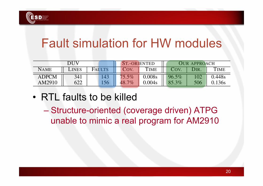
Fault simulation for HW modules
• RTL faults to be killed – Structure-oriented (coverage driven) ATPG
unable to mimic a real program for AM2910
20
DUV ST.-ORIENTED OUR APPROACH
NAME LINES ASS. ACT. TIME ACT. DIR. TIME
Breadmaker 2006 20 30% 0.008s 100% 7 0.064sRPC-3D-door 22043 63 98% 0.012s 100% 168 0.132sDSC-2L 37545 14 35% 0.004s 100% 114 1.676s
TABLE I. EXPERIMENTAL RESULTS (EMBEDDED SW APPLICATIONS).
DUV ST.-ORIENTED OUR APPROACH
NAME LINES FAULTS COV. TIME COV. DIR. TIME
ADPCM 341 143 75.5% 0.008s 96.5% 102 0.448sAM2910 622 156 48.7% 0.004s 85.3% 506 0.136s
TABLE II. EXPERIMENTAL RESULTS (HARDWARE COMPONENTS).
V. EXPERIMENTAL RESULTS
The effectiveness of the proposed framework has been eval-uated in two ways. First, we evaluated its capability in the con-text of dynamic ABV of C++ embedded software applications.As briefly summarized in the introduction, dynamic ABVrequires to stimulate the DUV with high-quality sequencessuch that assertion checkers can be actually activated to avoidvacuous passing of the corresponding assertions. The secondexperiments has been conducted to measure the quality of theproposed framework in the context of traditional fault simu-lation of SystemC RTL hardware components. In both cases,the framework has been compared, from the effectiveness pointof view, with respect to a structure-oriented (coverage-driven)generator included into a commercial verification suite [18].We do not report such a comparison with respect to UVMsince our approach and UVM have the same capability fromthe point of view of (SAT/SMT) constraint-based generation.Thus, the most relevant comparison between UVM and ourapproach concerns the difference in the easiness of use andthe application domain, as described in the previous section.
Table I presents the results in the context of dynamicABV. Columns report benchmarks characteristics, i.e., theDUV name (NAME), the number of code lines (LINES) andthe number of defined assertions (ASS.), and results, in termsof percentage of fired assertions (ACT.) and time required forstimuli generation (TIME) by using both the structure-orientedengine and the proposed framework. The total number ofdirective lines written by means of the specification languagedefined in Section II is also reported (DIR.). To be fair, boththe generators have been required to create sequences of thesame length (thousands of test vectors). Our approach allowsto activate all the assertions for all the considered benchmarks,while the structure-oriented generator achieves a good activa-tion percentage only in one case. This is motivated by thefact that the activation of assertions for Breadmaker and DSC-2L depends on conditions which cannot be simply guaranteedby a structure-oriented generator. Indeed, for the most ofassertions, an initialization sequence is required to bring theapplication in a particular state from which their activationis guaranteed. Such initialization sequences, reproducing thereal environment where the application operates, can be easilyobtained by reproducing the required behaviours with thespecification language described in Section II. Execution timesshow that our approach is more expensive, in particular forDSC-2L where an extensive use of the SMT-based Constraintgenerator has been required. Indeed, generation time is almostnegligible for all benchmarks.
Table II reports a similar analysis for the fault simula-tion context. In this case, the number of assertions and thepercentage of their activations are replaced by the number offaults (FAULTS) and the achieved fault coverage (COV.). Thefault model defined in [19] has been adopted. The proposedapproach provides an higher fault coverage than the structure-
oriented engine showing its effectiveness also for a “coverage-driven” goal. However, the number of directives that weneeded to write for the AM2910 micro controller is quite highcompared to the complexity of the DUV. This is due to thenecessity of mimic the behaviour of an AM2910 program bymeans of the specification language of Section II, to accuratelystimulate its instruction set architecture, which is composedof 16 instructions. On the other hand, for the same reason,the coverage achieved by the structure-oriented approach isvery low due to its inability of simulating a real operatingenvironment for the micro controller.
VI. CONCLUSIONS
The paper presented a stimuli specification language anda corresponding stimuli generation engine targeting the re-production of specific conditions, as required, for example,by scenario-based testing and dynamic ABV. The languageallows to intuitively write directives for the engine to generateconstraint-based stimuli sequences that respect the desired con-ditions. In comparison to the popular UVM environment, ourapproach is intended to provide a simpler way of specifyingsequence behaviours, it works independently from the abstrac-tion level and from the DUV implementation language, and itcan be used for the hardware as well as the software domain. Incomparison to a structure-oriented engine we showed that ourframework generates stimuli which more effectively activateassertions and achieves higher fault coverage.
REFERENCES
[1] D. Pradhan and I. Harris, Practical Design Verification. Cambridge Univ Press,2009.
[2] C. Cadar, D. Dunbar, and D. Engler, “Klee: Unassisted and automatic generationof high-coverage tests for complex systems programs,” in Proc. of OSDI, 2008,pp. 209–224.
[3] S. M. Plaza, I. L. Markov, and V. Bertacco, “Random stimulus generation usingentropy and XOR constraints,” in Proc. of ACM/IEEE DATE, 2008, pp. 664–669.
[4] G. Di Guglielmo, M. Fujita, F. Fummi, G. Pravadelli, and S. Soffia, “EFSM-based model-driven approach to concolic testing of system-level design,” in Proc.of ACM/IEEE MEMOCODE, 2011, pp. 201–209.
[5] S. Yang, R. Wille, D. Grobe, and R. Drechler, “Coverage-driven stimuli genera-tion,” in Proc. of IEEE DSD, 2012, pp. 525–528.
[6] C. Kaner, “An introduction to scenario testing,” Lecture Notes, Center for SoftwareTesting Education and Research, Florida Institute of Technology, 2003.
[7] D. Tabakov, “Dynamic assertion-based verification for SystemC,” Ph.D. disserta-tion, 2010, Rice University.
[8] R. A. DeMillo and A. J. Offutt, “Constraint-based automatic test data generation,”IEEE Trans. Softw. Eng., vol. 17, no. 9, pp. 900–910, 1991.
[9] Accellera Organization, “Universal Verification Methodology,”2012. [Online]. Available: http://www.accellera.org/downloads/standards/uvm/uvm_users_guide_1.1.pdf
[10] M. F. Oliveira, C. Kuznik, H. M. Le, D. Grosse, F. Haedicke, W. Mueller,R. Drechsler, W. Ecker, and V. Esen, “The system verification methodology foradvanced TLM verification,” in Proc. of IEEE/ACM/IFIP CODES+ISSS, 2012,pp. 313–322.
[11] Accellera Organization, “SystemC Verification Library,” 2012. [Online].Available: http://www.accellera.org/activities/committees/ systemc-verification/
[12] D. Grosse, R. Ebendt, and R. Drechsler, “Improvements for constraint solving inthe Systemc Verification Library,” in Proc. of ACM GLSVLSI, 2007, pp. 493–496.
[13] G. Di Guglielmo and G. Pravadelli, “A testbench specification language forSystemC verification,” in Proc. of IEEE/ACM/IFIP CODES+ISSS, 2012, pp. 333–342.
[14] “Random boost library.” [Online]. Available: http://www.boost.org/
[15] A. Cimatti, A. Griggio, B. J. Schaafsma, and R. Sebastiani, “The MathSAT5 SMTsolver,” in TACAS, ser. Lecture Notes in Computer Science, vol. 7795. Springer,2013, pp. 93–107.
[16] C. Barrett, A. Stump, and C. Tinelli, “The SMT-LIB Standard: Version 2.0,” inProc. of International Workshop on Satisfiability Modulo Theories, 2010.
[17] “UVM -ML Open Architecture,” 2013. [Online]. Available:http://forums.accellera.org/files/file/ 65-uvm-ml-open-architecture/
[18] “radCHECK.” [Online]. Available: http://www.verificationsuite.com
[19] V. Guarnieri, G. Di Guglielmo, N. Bombieri, G. Pravadelli, F. Fummi, H. Hantson,J. Raik, M. Jenihhin, and R. Ubar, “On the reuse of TLM mutation analysis atRTL,” J. Electron. Test., vol. 28, no. 4, pp. 435–448, 2012.

CONCLUSIONS
21

Concluding remarks • Specification
language and generation engine for SBV and ABV – Simpler than UVM – Independent from
• abstraction level • DUV language
– Working for • embedded SW/HW
22
Orient your stimuli generation!

23