SIMPLEX™ SAMPLING VALVE
32
D O N ’ T G A M B L E W I T H Y O U R S A M P L E ™ SIMPLEX™ SAMPLING VALVE USER MANUAL
Transcript of SIMPLEX™ SAMPLING VALVE

D O N ’ T G A M B L E W I T H Y O U R S A M P L E ™
SIMPLEX™ SAMPLING VALVE
User ManUal

DOCUMENT VERSION LOG
The table below lists previous versions of this User Manual and states the major changes between versions.This version list is introduced in November 2015.
Version # Version date Major changes from previous versions1 April 2016 Latest version without version log
INTRODUCTION: MANUFACTURER: KeofittA/S Kullinggade 31 5700Svendborg,Denmark
TYPE: SIMPLEX™SAMPLINGVALVE YEAR OF INTRODUCTION: 2007 YEAR OF REVISED DESIGN: 2014 MANUAL LAST UPDATED: Apr. 2016
TheEnglishversionofthisManualisthegoverningversionanditistheonlyauthorizedversion.Consequently,KEOFITTcannot be held liable for other versions including translations of this Manual.


CONTENTS1. PRESENTATION .............................................................................................................................7
1.1Definitionofterms ............................................................................................................................71.2Quickstart ........................................................................................................................................9
2. CLEANING – DISINFECTION – STERILISATION ..........................................................................102.1Clean-In-Place(CIP) ....................................................................................................................... 102.2Disinfection.................................................................................................................................... 10
3. VALVE FUNCTION ........................................................................................................................12
4. EVERYDAY USE OF THE VALVE ...................................................................................................134.1Pre-productiontreatment ............................................................................................................. 134.2Chemicalcleaning(CIP)anddisinfection .................................................................................... 134.3Sampling ......................................................................................................................................... 135. valve .................................................................................................................................................. 145.1 Material ........................................................................................................................................... 145.2Certificate ....................................................................................................................................... 145.3Pressure(max.) .............................................................................................................................. 145.4Surfacefinish ................................................................................................................................. 145.5Viscosity: ......................................................................................................................................... 145.6Flow ................................................................................................................................................ 15
6. VALVES .........................................................................................................................................17
7. PARTS & ACCESSORIES ..............................................................................................................18
8.MOUNTING INSTRUCTIONS ..........................................................................................................198.1 Location .......................................................................................................................................... 198.2 Before welding ............................................................................................................................... 19
9. WELDING INSTRUCTIONS ............................................................................................................209.1 Welding method ............................................................................................................................. 209.2Guidelineweldingvalues ............................................................................................................... 20
10. BLOCK DIAGRAMS .....................................................................................................................2110.1KeofittvalvetypeT(tank) ............................................................................................................ 2110.2KeofittvalvetypeP(pipe) ............................................................................................................ 2110.3Keofittvalvetypeclampconnection ........................................................................................... 2210.4KeofittvalvetypeVarivent® ........................................................................................................ 22
11. MAINTENANCE ...........................................................................................................................2311.1Sparepartslist ............................................................................................................................. 2311.2Assemblyofvalvebodyandhead .............................................................................................. 2411.3Disassemblyofvalvehead ......................................................................................................... 25
12. INSTRUCTIONS ON REPLACING PTFE MEMBRANE .................................................................26
13. UPGRADE FROM SILICONE/EPDM TO PTFE MEMBRANE ........................................................2713.1FormanuallyoperatedvalveheadstypeH,KandQ ............................................................... 27

14. MEMBRANES .............................................................................................................................2814.1Siliconemembrane-art.no.600051 ........................................................................................ 2814.2EPDMmembrane-art.no.600052 .......................................................................................... 2914.3FFKMmembrane-art.no.600053 ........................................................................................... 3014.4PTFEmembrane-art.no.850055 ............................................................................................ 31

K E O F I T T U S E R M A N U A L P A G E 7
1. PRESENTATIONTheKeofittSimplexsamplingvalveisavalve,whichcanbereadilysanitizedandwhichmeetsbothhygienicandprocessdesignrequirements.Thismeansthataneffectivecleaningofthesamplingvalvecanbecarriedoutbetweenproductionbatches.TheKeofittSimplexvalveisEHEDGTypeELauthorised.TheEHEDGTypeELcertificationisaEuropeanstandardanditincludesadditionaltestsofbacterialingressoncomponentsthatareindirectcontactwiththesampleaftertheCIPprocess.Thevalveisusedinawiderangeofprocessingindustries,suchasbreweries,dairies,andthepharmaceutical and biotechnological industries.
1.1 Definition of termsInordertoeasethereadingofthismanualandtoavoidanymisunderstanding,pleaserefertothedefinitionoftermsinthetablebelow:
TERM DEFINITION
3-ASanitaryStandard 3-ASSIisanindependent,not-for-profitUScorporationdedicatedtoadvancinghygienicequipmentdesignforthefood,beverageandpharmaceutical industries.
Acids Anacidisachemicalsubstancewhoseaqueoussolutionsarecharacterizedbyasourtasteandtheabilitytoreactwithbasesandcertainmetals(likecalcium)toformsalts.AqueoussolutionsofacidshaveapHoflessthan7.AlowerpHmeansahigheracidity,andthusahigherconcentrationofpositivehydrogenionsinthesolution.Removeslimestoneandmostmineraldeposits.
Alkali Alkalisareallbases,whichformhydroxideions(OH-)whendissolvedinwater.Theterms“base”and“alkali”areoftenusedinterchangeably.AlkalishaveapHvalueabove7.Alkalisdissolvesfatandoil,destroysproteinandattackslightmetal.
Aseptic sampling Theprocessofwithdrawingasamplefromtheproductionequipmentthroughaclosedcircuit,whichhasbeensterilisedandkeptsterilewithnoexposuretotheambientduringthesamplingprocess.
Bioload SeeMicrobialload.Bioburden SeeMicrobialload.ChemicalSterilant Afewdisinfectantswillkillsporeswithprolongedexposuretimes(3–12
hours);thesearecalledchemicalsterilants.Chlorine ChlorineisachemicalelementwithsymbolClandatomicnumber17.It
belongstothehalogengrouptogetherwithforinstanceiodine.Itisastrongoxidizingagentandreactswithmanysubstances.Thesepropertiesmakechlorinecompoundsefficientdisinfectants.
CIP AbbreviationofClean-In-Place.Theprocessofcleaningaprocesscomponent(likeasamplingvalve)withoutremovingitfromtheproductionline.
Cleaning Removal,usuallywithdetergentandwaterorenzymecleanerandwater,ofadherent visible soil on a surface.
Complexingagent Asubstancecapableofformingacomplexcompoundwithanothermaterialinsolution.Improvesthecleaningpropertiesofadetergent.
Contacttime The time span during which the item is in contact with the detergent or the disinfectant.

K E O F I T T U S E R M A N U A L P A G E 8
Enzymes Molecules,whichareaddedtocleaningagentstoeasetheremovalofspecificorganicmaterial.Assuressamecleaningeffectatalowertemperature.
Disinfectant Usuallyachemicalagentthatdestroysharmfulmicroorganismsbutmightnotkillbacterialspores.
Disinfection Thermalorchemicaldestructionofmicroorganisms.Disinfectionislesslethalthansterilisation,becauseitdestroysmostrecognisedmicroorganismsbutnotnecessarilyallmicrobialforms(e.g.bacterialspores).
Detergent Acleaningagentthathasnoantimicrobialeffect,butindilutedsolutionsgood cleaning properties.
EHEDG AbbreviationfortheEuropeanHygieneEngineeringandDesignGroup.EHEDGisaconsortiumofequipmentmanufacturers,foodindustries,research institutes as well as public health authorities promoting safe foodbyimprovinghygienicengineeringanddesigninallaspectsoffoodmanufacture.
Electropolishing Electropolishingisanelectrochemicalprocessbywhichthehighpointswithinthemicroscopicsurfacetextureareremovedandthecornersrounded.ThisresultsinReducedProductAdhesion,EaseofCleaningandImprovedCorrosionResistance.
Exposuretime Periodinasterilisation/disinfectionprocessduringwhichtheitemisexposedtothesterilant/disinfectantatthespecificsterilisation/disinfectionparameters.
Flowpath Thepaththesampleflowsfromthetankorprocessequipmenttothesample recipient.
Germicidal Thepropertyofanagenttodestroymicroorganisms.Microbial load Thenumberandtypesofviablemicroorganismswithwhichanitemis
contaminated;alsocalledbioloadorbioburden.Microorganisms Animalsorplantsofmicroscopicsize.Asusedinfoodandpharmaceutical
industries,generallyreferstobacteria,fungi,virusesandbacterialspores.Peraceticacid Acommonlyuseddisinfectant,whichisefficientatlowtemperatureand
shortcontacttime.Relativelyharmlessasitdecomposesintocarbondioxide(CO2)andwater(H2O).
Processmedia Theproductintheprocessequipmentandtheproductfromwhichasampleistaken.
Representativesample Asamplewhichwhenitreachesthelaboratoryisstillidenticaltotheprocessmedia.Asamplewhichisinnowaycontaminatedoralteredduringneitherthesamplingprocessnorthetransporttothelaboratory.
Sanitization The application of a chemical agent that reduces the number of bacterial contaminantstoasafelevelasjudgedbythepublichealthauthorities.Theofficialsanitizerprotocolindicatesthat99.999%ofthespecifictestbacteriabekilledin30secondsundertheconditionsofthetest.
SIP AbbreviationforSterilise-In-Place.Theprocessofrenderingaprocesscomponent(likeasamplingvalve)sterilewithoutremovingitfromtheproduction line.
Spores Relativelywater-poorrestingcellssurroundedbyanimperviouscellwall,whichmakesthemrelativelyresistanttodisinfectantsandsterilants.Theyaredangerousastheycansurviveinadverseconditionsandre-emergeaslive bacteria at a later stage.

K E O F I T T U S E R M A N U A L P A G E 9
Sporicidal Thepropertyofanagentthatkillsspores.Steaming The process of using saturated steam under pressure as the sterilising
agent.Sterile Stateofbeingfreefromalllivingmicroorganisms.Inpractice,usually
describedasaprobabilityfunction,e.g.,astheprobabilityofanymicroorganism surviving sterilisation being one in one million.
Sterilant Afewdisinfectantswillkillsporeswithprolongedexposuretimes(3–12hours);thesearecalledchemicalsterilants.
Sterilisation Validatedprocessusedtorenderanitemfreeofallformsofviablemicroorganisms.Inasterilisationprocess,thepresenceofmicroorganismsisexpressedintermsofprobability.Althoughthisprobabilitycanbereducedtoaverylownumber,itcanneverbereducedtozero.
SterilityAssuranceLevel
Theprobabilityofaviablemicroorganismbeingpresentonanitemaftersterilisation.Usuallyexpressedas10–n;aSALof10-6means<1/1millionchance that a single viable microorganism is present on a sterilised item.
Tensides A tenside is a surfactant that reduces the surface tension of water and assures a faster and better contact between the detergent and the soil.
1.2 Quick startThetablebelowgivesyouanoverviewoftherelevantchapterstoreaddependingontheoperationsyouwanttoperformtoobtaintherequiredhygieniclevel.
Required hygienic level
4.1Pre-
prod
uctio
n tre
atm
ent
4.2Chemical
cleaningCIP
4.3Chemical
disi
nfec
tion
4.4Steam
ing
5.1Chemical
CIP
5.2Chemical
disi
nfec
tion
5.3Steam
st
erili
satio
n
5.4Sam
pling
Cleaning
Disinfection
Sterilisation

K E O F I T T U S E R M A N U A L P A G E 1 0
2. CLEANING – DISINFECTION – STERILISATION
2.1 Clean-In-Place (CIP)Thoroughcleaningofthevalveisaprerequisiteforproperdisinfectionorsterilisation.Cleaningofthevalveistheremovalofanyvisibleresidualproduct,itbeorganicorinorganic.Itmaybedoneusingeithersteam(continuoussteamwilleventuallyleadtosterility;SIP=Sterilise-In-Place)orasuitableliquiddetergent.Cleaningistheremovalofadheringsoilfromtheenvironmentandfromtheprevioussample(totheextentithasnotbeenremovedbytherecommendedpost-samplecleaning).Cleaningisusuallyperformedbyflushingwithwaterfollowedbyathoroughwashingwithanappropriatedetergentandfinishedoffwithathoroughrinsingwithwater.Dependingontheactualprocessmediatheproperdetergentmustbedeterminedincooperationwithyourusualsupplierofdetergents.ThecompanyNovadanApS,Kolding,Denmark-www.novadan.dk,hassuppliedthegenerictablebelowforyourconvenience.
What to clean for Generic cleaning agents Comments
Fat AlkaliandTensides Heatwillfacilitatethecleaningprocessas the fat melts
Protein Alkali,Acids,TensidesandChlorine Coagulationandburningwhenheated,whichmakestheproducthardtoremove.
Sugar,Salt Waterisusuallysufficientastheproduct is water soluble
Sugarcarameliseswhenheated,turningintoahardstickysubstance,whichisdifficulttoremove
Minerals Acids,Complexingagent OftenseenaslimescaleBiofilm AlkaliandChlorine,Peraceticacid,
possiblyEnzymesBiofilmisanaccumulatedmassofmicroorganismsthatistightlyadheredtoasurfaceandcannotbeeasilyremoved.
Starch AlkaliandChlorine
2.2 DisinfectionAlthoughCIPremovesallvisibleresiduesoftheprocessmediathevalvesurfaceswillstillbecontaminatedonamicroscopiclevel.Dependingonyouractualprocessmediaitwillbenecessarytocarryoutadisinfectionoperationinordertoa)reducethemicrobialloadtoanacceptablelevel(alsoreferredtoasSanitization)orb)destroycriticalmicroorganisms,butnotnecessarilyallmicrobialforms(e.g.bacterialspores).Thedisinfectionprocessmaybecarriedoutinoneoftwowaysandtodifferentlevelsofdisinfectiondependingona)theinitialmicrobialloaddistribution,b)therequiredhygieniclevelandc)thetype,exposuretimeandconcentrationofthechemicalsused(ifusingachemicaldisinfectant):
• Bysteaming(inacontinuedprocessaftersteamcleaning)• Byapplyingoneormoresuitableliquidchemicaldisinfectants
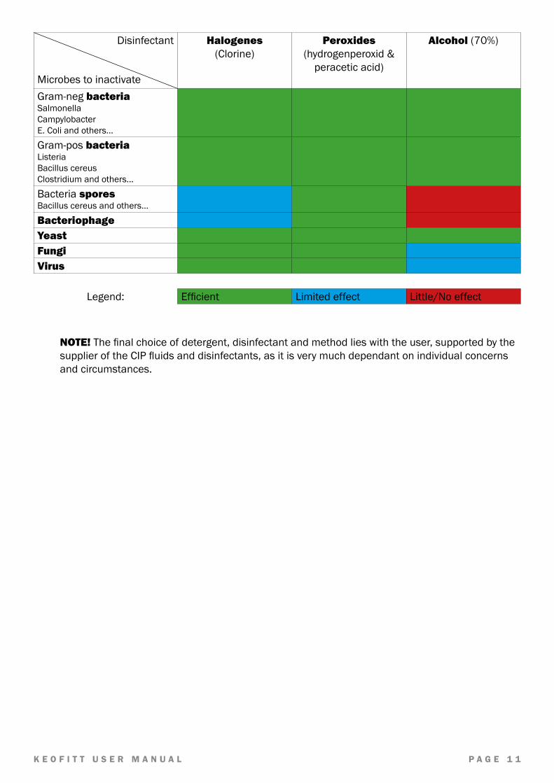
Thereareanumberofchemicaldisinfectants.Itisimportanttochoosetherightone,therightconcentrationandcontacttimeandtherightmethodforyourcurrentapplication.Yourusualsupplierofchemicaldisinfectantscansupportyouinchoosingtherightdisinfectantforyourprocessmediaandthespecificgroupofmicroorganismsyouareaimingat.ThecompanyNovadanApS,Kolding,Denmarkhassuppliedthetablebelow,asapreliminaryindicationofwhichtypeofdisinfectanttouse:
K E O F I T T U S E R M A N U A L P A G E 1 1
Disinfectant
Microbes to inactivate
Halogenes(Clorine)
Peroxides(hydrogenperoxid&peraceticacid)
Alcohol(70%)
Gram-negbacteriaSalmonellaCampylobacterE.Coliandothers...
Gram-posbacteriaListeriaBacillus cereusClostridiumandothers...
Bacteria sporesBacillus cereus and others...
BacteriophageYeastFungiVirus
Legend: Efficient Limited effect Little/Noeffect
NOTE!Thefinalchoiceofdetergent,disinfectantandmethodlieswiththeuser,supportedbythesupplieroftheCIPfluidsanddisinfectants,asitisverymuchdependantonindividualconcernsand circumstances.

K E O F I T T U S E R M A N U A L P A G E 1 2
3. VALVE FUNCTIONThevalveisdesignedtoregularlytakerepresentativenon-sterilerandomsamplesintheproductionprocess. The valve is therefore designed such that effective cleaning and sampling can be carried out. Forsterilesampling,pleaserefertootherKeofittsamplingvalvessuchasKeofittW9orKeofittReflex.CleaningiscarriedoutbysimplyopeningthevalveduringtheCIPprocessallowingthecleaningagentstoflowthroughthevalveanditsoutlet,whichshouldbeconnectedtoaby-passlooporotherclosedcircuittopreventtheoperatorfrombeingexposedtotheCIPliquid.
NOTE!Themembranefunctionsbothasadynamicpackinginthevalveseatandasahygienic,staticpackingagainstthevalvebody.
WARNING• Thevalveisdesignedforuseinworkingconditionsofupto6bar(g)pressureandtemperatures
ofupto121C.Itisthereforeimportanttobeawarethattherubberplug(designedformax.3bar(g))orthesteelplug(designedformax.10bar(g))maybeforcedoutathighspeed,ifnotseatedproperly
• AlwaysremembertousesafetygoggleswhenCIPping,takingsamplesandallotheroperationsof the sampling valve
IMPORTANT• IfvacuumoccursduringtheprocessitispreferabletousePTFEmembranesasrubber
membranesrisktobesuckedhardintotheseat.Neveropensamplingundervacuumconditionsduetothehighriskofcontaminatingtheprocess.
• Themembraneisavailablein3differentqualities:Silicone,EPDMandPTFE• TheSiliconemembranehastheadvantagethatitingeneralcanwithstandhightemperatures,
but it cannot tolerate moisture condensation resulting from steam sterilisation• TheEPDMmembraneisbetterabletocopewiththecondensationinthesteamandat
thesametimeitcanbeusedwithamajorityofCIPfluidsanddisinfectantsinnormalconcentrations
• ThePTFEmembraneresistsallCIPfluidsanddisinfectantsexcepthighlyoxidisingacidsinhighconcentrations

K E O F I T T U S E R M A N U A L P A G E 1 3
4. EVERYDAY USE OF THE VALVEThischaptergivesanintroductiontohowthesamplingvalveworksindifferentoperatingconditions.Forspecificoperatorinstructionspleaserefertothechapter“VALVEOPERATIONS”.
4.1 Pre-production treatmentBeforeeverynewproductionbatchthesamplingvalveiscleaned(andpossiblydisinfected)togetherwiththetankorvesselortheentireproductionline.MakesurethevalveisinitsopenpositionduringtheinitiallineCIPtoallowcleaningofthevalveseatand the membrane contact surface. ConnectareturnhosetothevalveoutletporttoleadtheCIPfluidbackintotheCIPcircuit.Remembertoclosethevalveafterthefinalrinseandpriortostartingupthenextproductionbatch.
4.2 Chemical cleaning (CIP) and disinfectionThevalvechamberandthevalveportmustbecleanedbothimmediatelyafterandbeforeeachsampling.Cleaningafterthesamplingistoremoveanyproductresiduesbeforetheysticktothevalveinterior.Cleaningbeforesamplingistoreducetheriskofcontaminatingthesample(andpossiblytheproductionbatch)byremovinganyairborneorothercontaminantsthatmighthavesettledonthevalvesincethelastsamplewastaken.Cleaningiscarriedoutbysquirtingajetofcleaningagentintothevalveport.Similarlydisinfectioniscarriedoutsquirtingadisinfectantintothevalveport.Rinsingisdoneinthesamewayusingcleanwaterorsimilar.
Just prior to sampling the valve port is cleaned
4.3 SamplingOncethecleaningisaccomplishedtakingasampleisdonebyopeningthevalveandclosingitagainwhentheriquiredsamplevolumeisobtained.
•
K E O F I T T U S E R M A N U A L P A G E 1 4
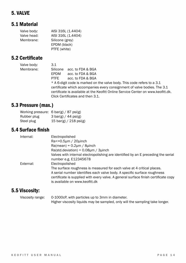
5. VALVE
5.1 MaterialValvebody: AISI316L(1.4404)Valvehead: AISI316L(1.4404)Membrane: Silicone(grey)
EPDM(black) PTFE(white)
5.2 CertificateValvebody: 3.1Membrane: Silicone acc.toFDA&BGA
EPDM acc.toFDA&BGA PTFE acc.toFDA&BGA
*A6-digitcodeismarkedonthevalvebody.Thiscodereferstoa3.1certificatewhichaccompanieseveryconsignmentofvalvebodies.The3.1certificateisavailableattheKeofittOnlineServiceCenteronwww.keofitt.dk.ClickCertificatesandthen3.1.
5.3 Pressure (max.)Workingpressure: 6bar(g)/87psi(g)Rubberplug 3bar(g)/44psi(g)Steelplug 15bar(g)/218psi(g)
5.4 Surface finishInternal: Electropolished
Ra<=0.5µm/20µinch Ra(mean)=0.2µm/8µinch Ra(std.deviation)=0.08µm/3µinch
ValveswithinternalelectropolishingareidentifiedbyanEprecedingtheserialnumbere.g.E12345678
External: Electropolished The surface roughness is measured for each valve at 4 critical places. Aserialnumberidentifieseachvalvebody.Aspecificsurfaceroughnesscertificateissuppliedwitheveryvalve.Ageneralsurfacefinishcertificatecopyisavailableonwww.keofitt.dk
5.5 Viscosity:Viscosityrange: 0-1000cP,withparticlesupto3mmindiameter. Higherviscosityliquidsmaybesampled,onlywillthesamplingtakelonger.

K E O F I T T U S E R M A N U A L P A G E 1 5
5.6 FlowThegraphsbelowillustrate(forwaterat20°C/68°F)thefollowing:
• PressuredropacrossvalveasafunctionoftheflowfordifferentpositionsoftheturnknobBasedonthetankpressureandtherequestedsampleflowthegraphsmaybeusedtogetanindicationof to which degree the valve must be opened.
Thegenerallyacceptedsamplingtimeisaround10sec.forsmallsamplesandaround30sec.forlarg-ersamples.Asusualsamplesizesarebetween100mland1000mltheneededflowliesfrom600to2000ml/min.Asthepressureonthesamplesideusuallyis0bar(g)thepressuredropacrossthevalveequalstheprocesspressure(tankpressureorlinepressure).
Thevolumeflowthroughavalveisgivenby:
�
kv = Qρ
1000 × ∆p
Symbol Unit Description
�
kvm3/h Flowinm3/hthroughavalveatapressuredropof1barasdefinedinVDE/
VDInorm2173.
�
Q m3/h Volumeflowthroughthevalve
�
ρ kg/dm3 Densityofthefluid.ForWateritis1.
�
∆p bar Pressuredropacrossvalve.Asthegaugepressureatthevalveoutletusuallyis0bar(g)thepressuredropisoftenequaltothegaugepressureattheinput(theprocessside)

K E O F I T T U S E R M A N U A L P A G E 1 6
WARNING• Thevalveisdesignedforuseinworkingconditionsofupto6bar(g)pressureandtemperatures
ofupto121C.Itisthereforeimportanttobeawarethattherubberplug(designedformax.3bar(g))orthesteelplug(designedfor10bar(g))maybeforcedoutathighspeed,ifnotseatedproperly
• ForvalveheadsallowedunderATEXforGroupIIGD,Category2(zone1)bothhandleandtopofvalve heads N and Q must be cleaned before use
• Alwaysremembertowearsafetygoggleswhensteaming,CIPping,takingsamplesoranyotheroperations of the sampling valve
IMPORTANT• CIPfluidsarehazardous

K E O F I T T U S E R M A N U A L P A G E 1 7
6. VALVES
Forfurtherproductinformation-material,dimensionsetc.-pleaserefertothespecificdatasheetatwww.keofitt.dk
K E O F I T T U S E R M A N U A L P A G E 1 8
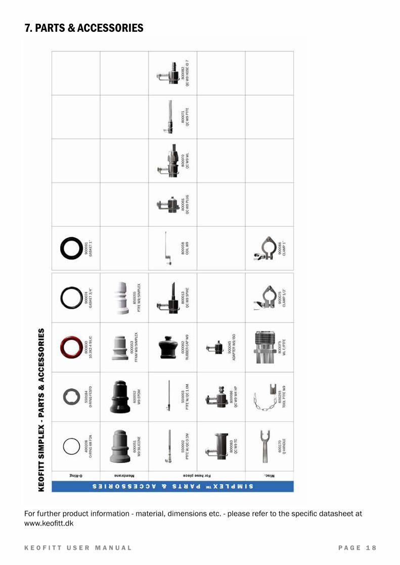
7. PARTS & ACCESSORIES
Forfurtherproductinformation-material,dimensionsetc.-pleaserefertothespecificdatasheetatwww.keofitt.dk

K E O F I T T U S E R M A N U A L P A G E 1 9
8.MOUNTING INSTRUCTIONS
8.1 LocationThevalveshouldalwaysbelocatedwithitscentrelineinahorizontalpositionandwiththehosepieceinaverticalpositionpointingdownwardsasshownonthefigure.Onlywiththisorientationthevalvewillbe self draining.
8.2 Before weldingRemembertodisassemblethevalvebodyandhead.Thevalvebodyandheadmustbeseparatedduringwelding.Rubberplugs,chainandmembranemustberemovedfromthevalvebody,asotherwiseheat from the welding process will damage them.

K E O F I T T U S E R M A N U A L P A G E 2 0
9. WELDING INSTRUCTIONS
Valvesforweldingareavailableintwotypes:T(tank)andP(pipe).1. FortypeT(tank)itisnecessarytodrillaholeø28mmintothetankwall,andthenfitthe
valveintothisholeflushwiththeinsideofthetank.Weldingshouldbecarriedoutasapenetration welding. Materialthicknesslessthan4mm:Weldfrominside.Materialthicknessgreaterthan4mm:Weld from both outside and inside. SincetypeThasasolidendpiece,thevalvewillnotbedamagedbypenetrationwelding.However,theuseofpurgegasintheformofeitherArgonorFormiergasisrecommendedinorder to give the best result.
2. FortypeP(pipe)penetrationweldingmustbecarriedoutfromoutside.Thevalveismachinedwitharecess-likeshoulderontheoutsideoftheendpiecewhichgivesapproximatelythesamematerialthickness(1.5mmmaterialthickness)asinthepipewall. Thismachinedshouldercanbemodifiedaccordingtothecustomer’swishes.
IMPORTANT!• Whengrinding/polishingtheinternalweld,thevalveseatmustnotbetouched.
9.1 Welding methodTheweldingresultwillbebestifthefollowingmethodisused:Acollarismadeonthepipesectionsothatthevalvehasaflatcontactface.ThisflaringmustlooklikeaT-piece,asshownintheexamplebelow.
• Thepipesectionandthevalve’shosepiecesaresealedwithspongerubberorsimilar.• PurgegassuchasArgonorFormiergasisfedthroughthevalvebodyintothepipesectionand
thesystemisnowfilledwith6timestheestimatedvolumeofthepipesection.AllO2 is thus expelledfromthesystemandweldingcancommence.
• Weldingmusttakeplaceonlywiththepurgegascontinuallyflowinginthesystem.• Thegasremainsinthesystemuntiltheitemislukewarm,afterwhichtheset-upcanbe
dismantled.
9.2 Guideline welding valuesSimplex™samplingvalveweldedontoa2mm3”dairypipe:50-60Amp.ItshouldbenotedthatKeofittcansupplyallPtypevalvesweldedontoapipesectionaccordingtocustomerspecifications.Flaringisthusavoidedandonlyagirthweldisrequired.

K E O F I T T U S E R M A N U A L P A G E 2 1
10. BLOCK DIAGRAMS
10.1 Keofitt valve type T (tank)
10.2 Keofitt valve type P (pipe)

K E O F I T T U S E R M A N U A L P A G E 2 2
10.3 Keofitt valve type clamp connection
10.4 Keofitt valve type Varivent®

K E O F I T T U S E R M A N U A L P A G E 2 3
11. MAINTENANCETherubbermembraneshouldbereplacedeveryothermonth.PTFEmembranesshouldbereplacedevery12months.Intheeventofintensivesterilisationandcleaningitmaybenecessarytoreplaceitmorefrequently.Theappropriatereplacementfrequencyshouldbedeterminedbytheuserbystartingwithshortintervalsandcontinuouslyextendthetimeinuseintilonereachesthelimitofthemembrane’sdurability.Basedonthedesiredsafetymargintheuserthendecidesonthereplacementinterval to adapt.Fordisassemblyofvalvebodyandvalvehead,seeinstructions.
11.1 Spare parts list
1. Valvebody2. MembraneSilicone(grey)MembraneEPDM(black)MembranePTFE(White)3. Lowerstem(slightlydifferentshapeforPTFEmembrane)4. Steelbushing5. Spring6. Turnknob7. Tommybar

K E O F I T T U S E R M A N U A L P A G E 2 4
11.2 Assembly of valve body and head
Inordertodissassembleandassemblethevalvebodyandvalveheadpleaseperformthefollowingoperations:
1. SetthevalveheadattheOPENposition.FortypesHandKthisisdonebyturningpos.6clockwise.
2. Removethevalveheadpos.8.DON’Tuseawrench.Atommybarpos.7shouldbeusedfordisassemblyandassembly.Thisiscarriedoutbyturningpos.8anti-clockwiseuntillooseand then pulling the valve head off.
3. Refitthevalvehead(intheOPENposition)oncethenecessarypartshavebeenreplaced.Careshouldbetakennottodamagethethreads.Usesuitablelubricant.
WARNING!• Whenreplacingthemembrane,setthevalveheadintheOPENpositionbeforeitisunscrewed
andpulledoutofthevalvebody.Omittingtodosomayresultintwistingandcuttingofthemembrane.
• Don’tcleanthevalveheadinanultrasonicbathorbyimmersingitinadegreasingliquid,asitwillimpedetheproperfunctioningofthescrewaction.Whenindoubt,contactyourlocalKeofittdealer

K E O F I T T U S E R M A N U A L P A G E 2 5
11.3 Disassembly of valve headOvertimetheturnknobmaybecomehardertoturn,whichmayberemediesbyregreasingthethreadedpartoftheturnknob.Performthefollowingstepstotakethevalveheadapartafterhavingseparateditforthevalvebodyasexplainedinchapter11.2:
• Setthevalveheadinclosedposition• Pulloffthemembrane• Removethebushing• Fixthelowersteminaviceusingsoftjaws• Unscrewthevalveheadtopusingthetommybar(holditbackwhenitgetsloose,asthespring
willpushitout)• Pullbytheknobtoseparateitfromtheunionnut• Unscrewtheupperstemfromtheturnknob• Lubricatetheupperstem’sthreadedpartincontactwiththeturnknob
Assemblyisthesameinreverseorder,butpleasenote:• Discardthemembraneandreplacewithanewone• Pushthemembraneandthebushingtogethersothatthemembraneissituatedagainstthe
shoulder of the bushing

K E O F I T T U S E R M A N U A L P A G E 2 6
12. INSTRUCTIONS ON REPLACING PTFE MEMBRANE Toremoveanoldmembranefromthevalvehead:
1. OPENthevalve(leverpositionasinillustrationA).2. Unscrewthevalveheadfromthevalvebodyasdescribedinchapter13.2.3. CLOSEvalvehead(illustrationA).4. Pushthemembraneandbushingapart(illustrationB)untilthetoolformembranefitsunder
it. 5. Inserttoolformembrane,betweenthemembraneandthebushing(illustrationB).6. OPENvalvehead(illustrationC).7. Now the membrane is loosened from the valve head and can be replaced.
Toattachanewmembranetothevalvehead:8. SetthevalveheadtoCLOSEDposition(leverpositionasinillustrationB).9. Placethenewmembraneonvalvehead.10. MountthemembranebushingwiththenewTeflonmembranebypressingthemembrane
withyourhanduntilitclicks.11. SetthevalveheadinOPENposition.12. Insertthevalveheadintothevalvebody.13. CLOSEvalvehead.
IMPORTANT
• Oncethemembranehasbeenremovedfromthevalveheadtheclicksysteminthemembranemight be damaged. Therefore the membrane might be unsafe for further use and it is recommended not to use the membrane again.
• Donotusehammerorothertoolthatmightscratchthesurfaceofthemembrane.
A. B. C.

K E O F I T T U S E R M A N U A L P A G E 2 7
13. UPGRADE FROM SILICONE/EPDM TO PTFE MEMBRANE
13.1 For manually operated valve heads type H, K and Q
1. Closevalve.2. Pulloffthesilicone/EPDMmembrane.3. Takethebushingoff.(page30,pos.5)4. Putthevalveheadinvice.5. Turnthehex-nutcounterclockwiceuntilthemembraneseatandspringareloose.Putthe
newlowerstemforPTFEmembraneinthevice.6. Fitthenewspringonthenewlowerstem.7. Inserttherestofthevalveheadinthepinandpressfirmly.8. Turnthehex-nutclockwiseuntilthelowerstemisfirmlyinplace.Careshouldbetakennotto
damage the threads.9. Putthebushingoverthespring,thenplacePTFEmembraneonthelowerstemandpress
firmlyuntilitclicksinplace.10. Putthevalveheadinopenposition.11. Putvalveheadinvalvebodyandtighten.
IMPORTANT• Thisisadelicateproceduretobeperformedbyskilledpersonnelonly.• Usevicewithaluminiumgrips,toavoidscratchinganddamagingthevalvehead.• UsethespringsuppliedwiththePTFEkit.PTFEmembranesrequireadifferenttypeofspring
thanEPDMandsiliconemembranes.• Donotusehammerorothertoolthatmightscratchthesurfaceofthemembrane.
Upgrade kit 854155 consisting of:
Ident no. Part name Material
600340 LowerstemforPTFE AISI316L(1.4404)
850055 MembraneforW9™&Simplex™ PTFE
600411 SpringH-Q-K12bar(g) St.St.
K E O F I T T U S E R M A N U A L P A G E 2 8
14. MEMBRANES
14.1 Silicone membrane - art. no. 600051
Last updated 22-01-2015*For further information please visit keofitt.dk
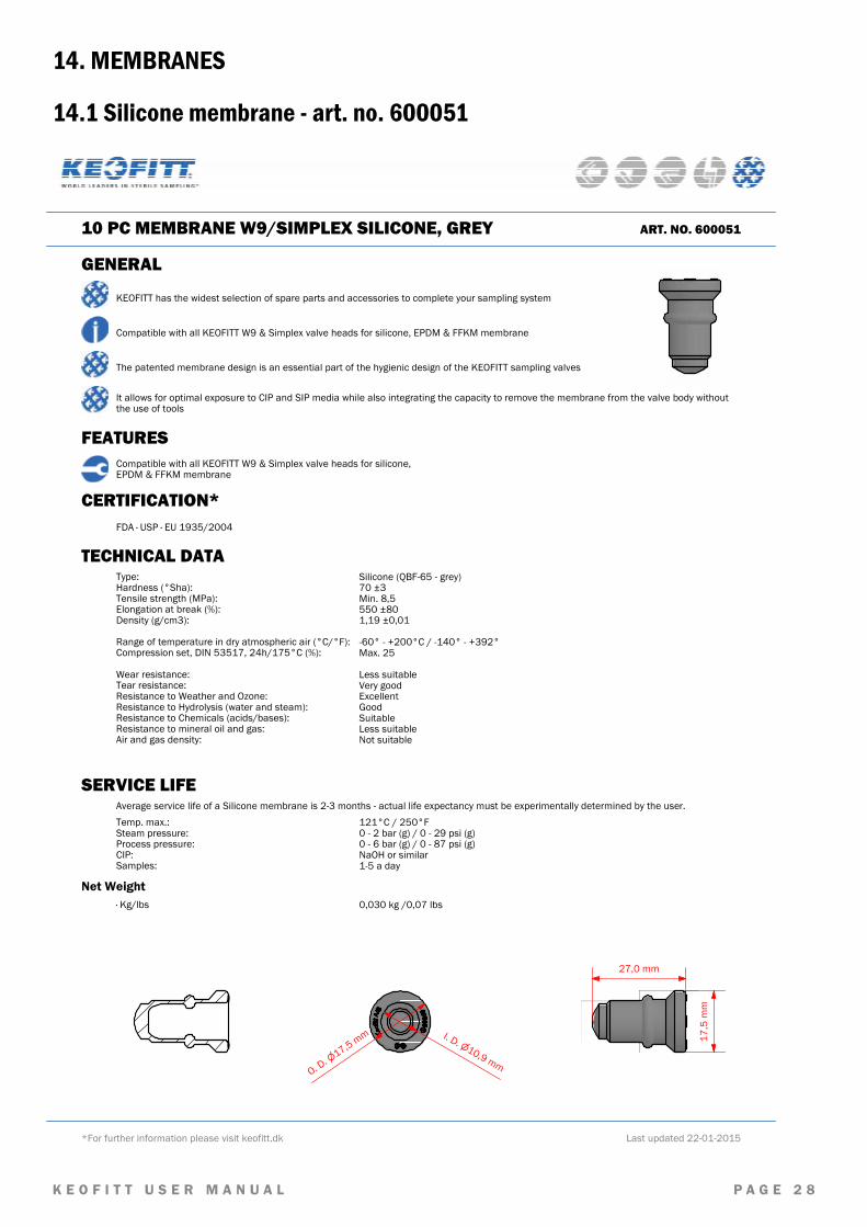
10 PC MEMBRANE W9/SIMPLEX SILICONE, GREY ART. NO. 600051
GENERAL
KEOFITT has the widest selection of spare parts and accessories to complete your sampling system
Compatible with all KEOFITT W9 & Simplex valve heads for silicone, EPDM & FFKM membrane
Compatible with all KEOFITT W9 & Simplex valve heads for silicone, EPDM & FFKM membrane
CERTIFICATION*FDA · USP · EU 1935/2004
TECHNICAL DATAType: Hardness (°Sha):Tensile strength (MPa):Elongation at break (%):Density (g/cm3): Range of temperature in dry atmospheric air (°C/°F):Compression set, DIN 53517, 24h/175°C (%): Wear resistance:Tear resistance:Resistance to Weather and Ozone:Resistance to Hydrolysis (water and steam):Resistance to Chemicals (acids/bases):Resistance to mineral oil and gas:Air and gas density:
Silicone (QBF-65 - grey)70 ±3Min. 8,5550 ±801,19 ±0,01 -60° - +200°C / -140° - +392° Max. 25 Less suitableVery goodExcellentGoodSuitableLess suitableNot suitable
Net Weight· Kg/lbs 0,030 kg /0,07 lbs
The patented membrane design is an essential part of the hygienic design of the KEOFITT sampling valves
It allows for optimal exposure to CIP and SIP media while also integrating the capacity to remove the membrane from the valve body without the use of tools
FEATURES
SERVICE LIFE Average service life of a Silicone membrane is 2-3 months - actual life expectancy must be experimentally determined by the user. Temp. max.:Steam pressure:Process pressure:CIP:Samples:
121°C / 250°F0 - 2 bar (g) / 0 - 29 psi (g)0 - 6 bar (g) / 0 - 87 psi (g)NaOH or similar1-5 a day
27,0 mm
10,9
I. D. mm17,5
O. D.
mm 17,5
mm

K E O F I T T U S E R M A N U A L P A G E 2 9
14.2 EPDM membrane - art. no. 600052
Last updated 22-01-2015*For further information please visit keofitt.dk
10 PC MEMBRANE W9/SIMPLEX EPDM BLACK ART. NO. 600052
GENERAL
KEOFITT has the widest selection of spare parts and accessories to complete your sampling system
Compatible with all KEOFITT W9 & Simplex valve heads for silicone, EPDM & FFKM membrane
Compatible with all KEOFITT W9 & Simplex valve heads for silicone, EPDM & FFKM membrane
CERTIFICATION*FDA · USP · EU 1935/2004
TECHNICAL DATAType: Hardness (°Sha):Tensile strength (MPa):Elongation at break (%):Density (g/cm3): Range of temperature in dry atmospheric air (°C/°F):Compression set, DIN 53517, 24h/175°C (%): Wear resistance:Tear resistance:Resistance to Weather and Ozone:Resistance to Hydrolysis (water and steam):Resistance to Chemicals (acids/bases):Resistance to mineral oil and gas:Air and gas density:
EPDM (EPL-60 - black)61 ±3Min. 16400 ±501,12 ±0,01 -40° - +140°C / -40° - +284° FMax. 16 Very goodVery goodExcellentExcellentVery goodNot suitableLess suitable
Net Weight· Kg/lbs 0,040 kg /0,09 lbs
The patented membrane design is an essential part of the hygienic design of the KEOFITT sampling valves
It allows for optimal exposure to CIP and SIP media while also integrating the capacity to remove the membrane from the valve body without the use of tools
FEATURES
SERVICE LIFE Average service life of an EPDM membrane is 2-3 months - actual life expectancy must be experimentally determined by the user. Temp. max.:Steam pressure:Process pressure:CIP:Samples:
121°C / 250°F0 - 2 bar (g) / 0 - 29 psi (g)0 - 6 bar (g) / 0 - 87 psi (g)NaOH or similar1-5 a day
27,0 mm
17,5
mm
10,9
I. D. mm
17,5
O. D.
mm

K E O F I T T U S E R M A N U A L P A G E 3 0
14.3 FFKM membrane - art. no. 600053
Last updated 01-07-2015*For further information please visit keofitt.dk
MEMBRANE W9 & SIMPLEX FFKM, WHITE ART. NO. 600053
GENERAL
KEOFITT has the widest selection of spare parts and accessories to complete your sampling system
Compatible with all KEOFITT W9 & Simplex valve heads for silicone, EPDM & FFKM membrane
Compatible with all KEOFITT W9 & Simplex valve heads for silicone, EPDM & FFKM membrane
CERTIFICATION*FDA · USP · EU 1935/2004
TECHNICAL DATAType: Hardness (°Sha):Tensile strength (MPa):Elongation at break (%):Density (g/cm3): Range of temperature in dry atmospheric air (°C/°F):Compression set, D395 70h/200°C (%): Wear resistance:Tear resistance:Resistance to Weather and Ozone:Resistance to Hydrolysis (water and steam):Resistance to Chemicals (acids/bases):Resistance to mineral oil and gas:Air and gas density:
FFKM (Perfluorelstomer)70 ±5131302,41 1° - +270°C / 34° - 518°F24 ExcellentExcellentExcellentExcellentExcellentExcellentExcellent
Net Weight· Kg/lbs 0,004 kg /0,009 lbs
The patented membrane design is an essential part of the hygienic design of the KEOFITT sampling valves
It allows for optimal exposure to CIP and SIP media while also integrating the capacity to remove the membrane from the valve body without the use of tools
FEATURES
SERVICE LIFE Average service life of a FFKM membrane is 12 months (or more) - actual life expectancy must be experimentally determined by the user. Temp. max.:Steam pressure:Process pressure:CIP:Samples:
250° C / 482° F0 - 2 bar (g) / 0 - 29 psi (g)0 - 6 bar (g) / 0 - 87 psi (g)NaOH or similar1-5 a day
27,0 mm
17,5
mm
17,5
O. D. mm
10,9
I. D.
mm
K E O F I T T U S E R M A N U A L P A G E 3 1
14.4 PTFE membrane - art. no. 850055
Last updated 19-12-2014*For further information please visit keofitt.dk
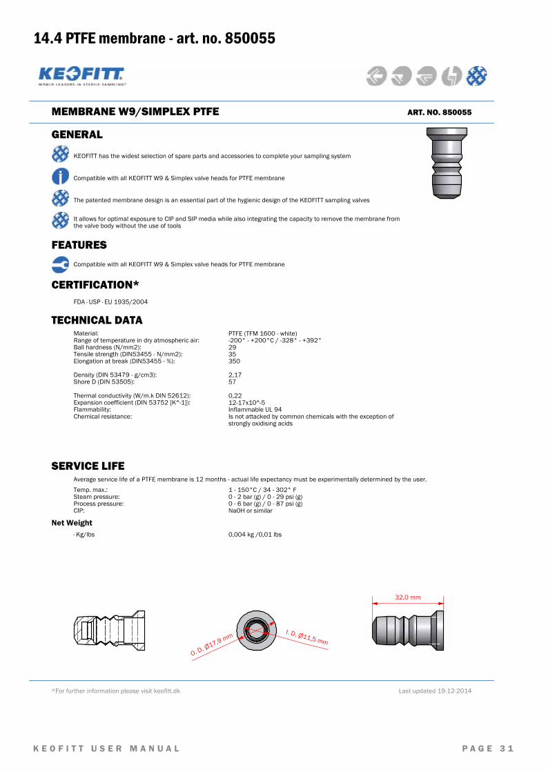
MEMBRANE W9/SIMPLEX PTFE ART. NO. 850055
GENERAL
KEOFITT has the widest selection of spare parts and accessories to complete your sampling system
Compatible with all KEOFITT W9 & Simplex valve heads for PTFE membrane
Compatible with all KEOFITT W9 & Simplex valve heads for PTFE membrane
CERTIFICATION*FDA · USP · EU 1935/2004
TECHNICAL DATAMaterial:Range of temperature in dry atmospheric air:Ball hardness (N/mm2):Tensile strength (DIN53455 - N/mm2):Elongation at break (DIN53455 - %): Density (DIN 53479 - g/cm3):Shore D (DIN 53505): Thermal conductivity (W/m.k DIN 52612):Expansion coefficient (DIN 53752 [K^-1]):Flammability:Chemical resistance:
PTFE (TFM 1600 - white)-200° - +200°C / -328° - +392°2935350 2,1757 0,2212-17x10^-5Inflammable UL 94Is not attacked by common chemicals with the exception of strongly oxidising acids
Net Weight· Kg/lbs 0,004 kg /0,01 lbs
The patented membrane design is an essential part of the hygienic design of the KEOFITT sampling valves
It allows for optimal exposure to CIP and SIP media while also integrating the capacity to remove the membrane from the valve body without the use of tools
FEATURES
SERVICE LIFEAverage service life of a PTFE membrane is 12 months - actual life expectancy must be experimentally determined by the user.Temp. max.:Steam pressure:Process pressure:CIP:
1 - 150°C / 34 - 302° F0 - 2 bar (g) / 0 - 29 psi (g)0 - 6 bar (g) / 0 - 87 psi (g)NaOH or similar
32,0 mm
11,5I. D.
mm17,9
O. D. mm

KEOFITT A/SKullinggade 31DK-5700 SvendborgDenmark
Phone +45 6316 7080Fax +45 6316 7081
Keofittreservestherighttochangetechnicaldatawithoutnotice!ForcompletesetofupdateddatasheetsandmanualsforKeofittproductspleaserefertoourwebpagewww.keofitt.dk