For 'Sesame Street,' the Direct Approach ('Sesame Street' set visit)
DON’T GAMBLE WITH YOUR SAMPLE™
SESAME™ SAMPLING VALVEUser Manual
SESAME USER MANUAL V. 6 PAGE 2
DOCUMENT VERSION LOG
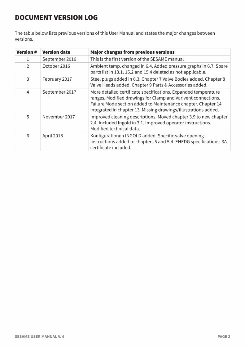
The table below lists previous versions of this User Manual and states the major changes between versions.
Version # Version date Major changes from previous versions1 September 2016 This is the first version of the SESAME manual2 October 2016 Ambient temp. changed in 6.4. Added pressure graphs in 6.7. Spare
parts list in 13.1. 15.2 and 15.4 deleted as not applicable.3 February 2017 Steel plugs added in 6.3. Chapter 7 Valve Bodies added. Chapter 8
Valve Heads added. Chapter 9 Parts & Accessories added.4 September 2017 More detailed certificate specifications. Expanded temperature
ranges. Modified drawings for Clamp and Varivent connections. Failure Mode section added to Maintenance chapter. Chapter 14 integrated in chapter 13. Missing drawings/illustrations added.
5 November 2017 Improved cleaning descriptions. Moved chapter 3.9 to new chapter 2.4. Included Ingold in 3.1. Improved operator instructions. Modified technical data.
6 April 2018 Konfigurationen INGOLD added. Specific valve opening instructions added to chapters 5 and 5.4. EHEDG specifications. 3A certificate included.
SESAME USER MANUAL V. 6 PAGE 3
INTRODUCTION: MANUFACTURER: Keofitt A/S Kullinggade 31 B & E 5700 Svendborg, Denmark
TYPE: SESAME™ SAMPLING VALVE PATENTS: DK 175721 B1. CN 100501219C. EP 1. 690 038 B1. US 7,658,201 B2 YEAR OF INTRODUCTION: 2016 MANUAL LAST UPDATED: April 2018
The English version of this Manual is the governing version and it is the only authorized version. Consequently, KEOFITT cannot be held liable for other versions including translations of this Manual.

SESAME USER MANUAL V. 6 PAGE 4
SESAME USER MANUAL V. 6 PAGE 5
CONTENTS1. PRESENTATION ............................................................................................................ 7
1.1 Definition of terms .............................................................................................................................71.2 Quick start ........................................................................................................................................10
2. CLEANING – DISINFECTION – STERILISATION .................................................................. 112.1 Clean-In-Place (CIP) .........................................................................................................................112.2 Disinfection ......................................................................................................................................112.3 Sterilisation ......................................................................................................................................122.4 Valve cleaning /disinfection /sterilisation .......................................................................................12
3. VALVE DESIGN AND FUNCTIONING ................................................................................. 143.1 Valve body configurations ................................................................................................................143.2 Valve head configurations ................................................................................................................143.3 Valve surfaces and roughness certificate ........................................................................................153.4 Rubber caps and steel caps ..............................................................................................................153.5 Sampling coil.....................................................................................................................................153.6 Membranes ........................................................................................................................................153.7 Parts and Accessories .......................................................................................................................163.8 Pressure and vacuum .......................................................................................................................16
4. EVERYDAY USE OF THE VALVE ....................................................................................... 184.1 Batch change cleaning .....................................................................................................................184.2 Chemical cleaning, CIP ....................................................................................................................184.3 Chemical disinfection ......................................................................................................................194.4 Steam sterilisation ...........................................................................................................................19
5. VALVE OPERATIONS .................................................................................................... 205.1 Chemical CIP ....................................................................................................................................215.2 Chemical disinfection ......................................................................................................................225.3 Steam sterilisation ...........................................................................................................................245.4 Sampling ..........................................................................................................................................26
6. TECHNICAL DATA......................................................................................................... 286.1 Material .............................................................................................................................................286.2 Certificate ..........................................................................................................................................286.3 Pressure (max.) .................................................................................................................................286.4 Temperature ......................................................................................................................................286.5 Surface finish .....................................................................................................................................296.6 Viscosity: ............................................................................................................................................296.7 Flow ..................................................................................................................................................29
7. VALVE BODIES ............................................................................................................ 31
8. VALVE HEADS .............................................................................................................. 32
9. PARTS & ACCESSORIES ................................................................................................. 33
10.MOUNTING INSTRUCTIONS .......................................................................................... 3410.1 Location ...........................................................................................................................................3410.2 Before welding ................................................................................................................................34
SESAME USER MANUAL V. 6 PAGE 6
11. WELDING INSTRUCTIONS ............................................................................................ 3511.1 Welding method ..............................................................................................................................3511.2 Guideline welding values ...............................................................................................................35
12. BLOCK DIAGRAMS ...................................................................................................... 3612.1 Keofitt valve type T (tank) ..............................................................................................................3612.2 Keofitt valve type P (pipe) ..............................................................................................................3612.3 Keofitt valve type clamp connection .............................................................................................3712.4 Keofitt valve type Varivent® ............................................................................................................37
13. MAINTENANCE .......................................................................................................... 3813.1 Maintenance ....................................................................................................................................3813.2 Spare parts list ................................................................................................................................3813.3 Disassembly and assembly of valve body and head .....................................................................3913.4 Replacing a rubber membrane .....................................................................................................3913.5 Instructions on replacing a PTFE membrane ...............................................................................4013.6 Cleaning valve head .......................................................................................................................41
14. FAILURE MODES ....................................................................................................... 4214.1 Broken membrane tip ....................................................................................................................4214.2 Broken membrane side..................................................................................................................4214.3 Broken integrated o-ring ...............................................................................................................4214.4 Cleaning the valve after a failure ...................................................................................................42
15. MEMBRANES ............................................................................................................. 4315.1 Silicone membrane - art. no. 890051 .............................................................................................4315.2 EPDM membrane - art. no. 890052.................................................................................................4415.3 PTFE membrane - art. no. 890055 ..................................................................................................4515.4 PTFE membrane - art. no. 893155 ..................................................................................................4615.5 PTFE membrane - art. no. 893255 ..................................................................................................47
SESAME USER MANUAL V. 6 PAGE 7
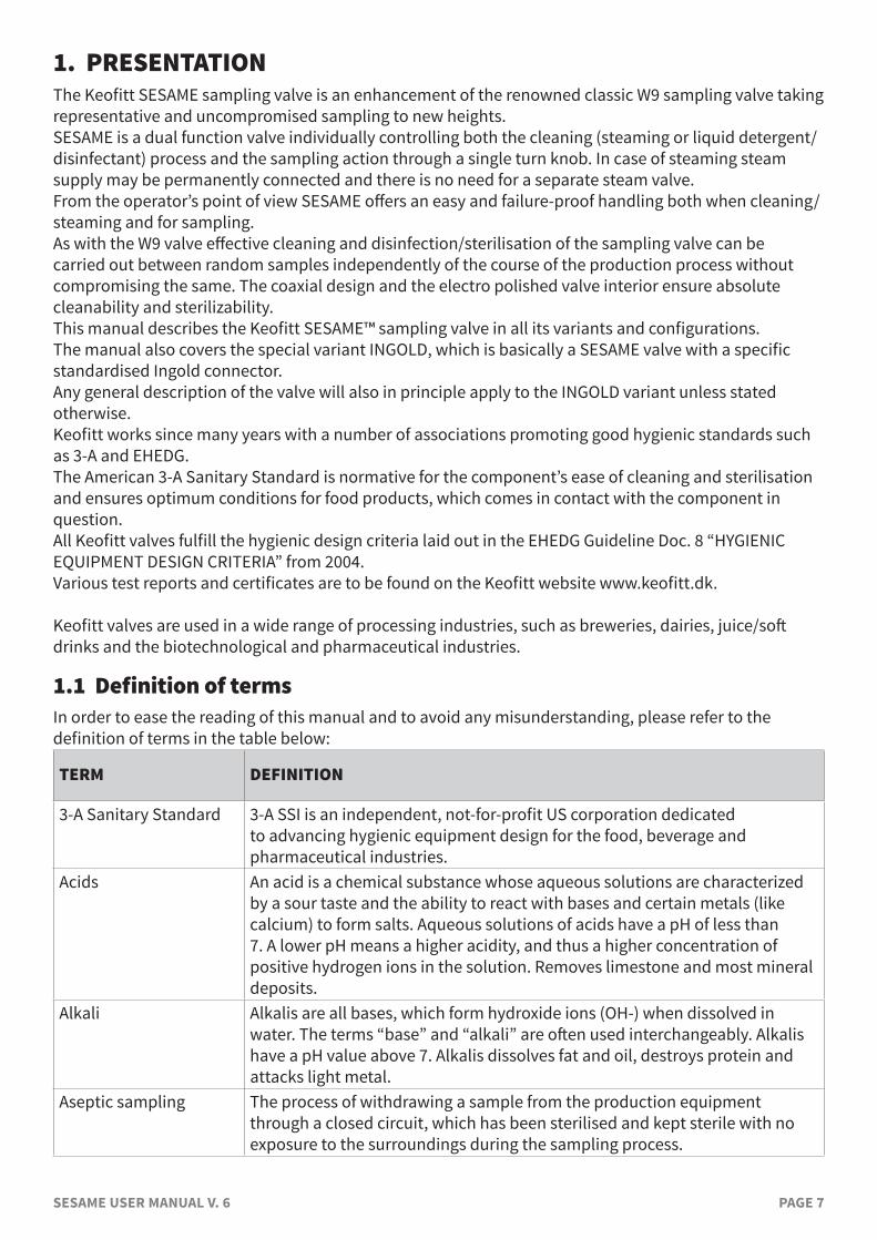
1. PRESENTATIONThe Keofitt SESAME sampling valve is an enhancement of the renowned classic W9 sampling valve taking representative and uncompromised sampling to new heights.SESAME is a dual function valve individually controlling both the cleaning (steaming or liquid detergent/disinfectant) process and the sampling action through a single turn knob. In case of steaming steam supply may be permanently connected and there is no need for a separate steam valve. From the operator’s point of view SESAME offers an easy and failure-proof handling both when cleaning/steaming and for sampling.As with the W9 valve effective cleaning and disinfection/sterilisation of the sampling valve can be carried out between random samples independently of the course of the production process without compromising the same. The coaxial design and the electro polished valve interior ensure absolute cleanability and sterilizability.This manual describes the Keofitt SESAME™ sampling valve in all its variants and configurations.The manual also covers the special variant INGOLD, which is basically a SESAME valve with a specific standardised Ingold connector. Any general description of the valve will also in principle apply to the INGOLD variant unless stated otherwise.Keofitt works since many years with a number of associations promoting good hygienic standards such as 3-A and EHEDG.The American 3-A Sanitary Standard is normative for the component’s ease of cleaning and sterilisation and ensures optimum conditions for food products, which comes in contact with the component in question. All Keofitt valves fulfill the hygienic design criteria laid out in the EHEDG Guideline Doc. 8 “HYGIENIC EQUIPMENT DESIGN CRITERIA” from 2004.Various test reports and certificates are to be found on the Keofitt website www.keofitt.dk.
Keofitt valves are used in a wide range of processing industries, such as breweries, dairies, juice/soft drinks and the biotechnological and pharmaceutical industries.
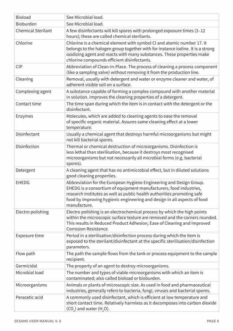
1.1 Definition of termsIn order to ease the reading of this manual and to avoid any misunderstanding, please refer to the definition of terms in the table below:
TERM DEFINITION
3-A Sanitary Standard 3-A SSI is an independent, not-for-profit US corporation dedicated to advancing hygienic equipment design for the food, beverage and pharmaceutical industries.
Acids An acid is a chemical substance whose aqueous solutions are characterized by a sour taste and the ability to react with bases and certain metals (like calcium) to form salts. Aqueous solutions of acids have a pH of less than 7. A lower pH means a higher acidity, and thus a higher concentration of positive hydrogen ions in the solution. Removes limestone and most mineral deposits.
Alkali Alkalis are all bases, which form hydroxide ions (OH-) when dissolved in water. The terms “base” and “alkali” are often used interchangeably. Alkalis have a pH value above 7. Alkalis dissolves fat and oil, destroys protein and attacks light metal.
Aseptic sampling The process of withdrawing a sample from the production equipment through a closed circuit, which has been sterilised and kept sterile with no exposure to the surroundings during the sampling process.
SESAME USER MANUAL V. 6 PAGE 8
Bioload See Microbial load.Bioburden See Microbial load.Chemical Sterilant A few disinfectants will kill spores with prolonged exposure times (3–12
hours); these are called chemical sterilants.Chlorine Chlorine is a chemical element with symbol Cl and atomic number 17. It
belongs to the halogen group together with for instance iodine. It is a strong oxidizing agent and reacts with many substances. These properties make chlorine compounds efficient disinfectants.
CIP Abbreviation of Clean-In-Place. The process of cleaning a process component (like a sampling valve) without removing it from the production line.
Cleaning Removal, usually with detergent and water or enzyme cleaner and water, of adherent visible soil on a surface.
Complexing agent A substance capable of forming a complex compound with another material in solution. Improves the cleaning properties of a detergent.
Contact time The time span during which the item is in contact with the detergent or the disinfectant.
Enzymes Molecules, which are added to cleaning agents to ease the removal of specific organic material. Assures same cleaning effect at a lower temperature.
Disinfectant Usually a chemical agent that destroys harmful microorganisms but might not kill bacterial spores.
Disinfection Thermal or chemical destruction of microorganisms. Disinfection is less lethal than sterilisation, because it destroys most recognised microorganisms but not necessarily all microbial forms (e.g. bacterial spores).
Detergent A cleaning agent that has no antimicrobial effect, but in diluted solutions good cleaning properties.
EHEDG Abbreviation for the European Hygiene Engineering and Design Group. EHEDG is a consortium of equipment manufacturers, food industries, research institutes as well as public health authorities promoting safe food by improving hygienic engineering and design in all aspects of food manufacture.
Electro polishing Electro polishing is an electrochemical process by which the high points within the microscopic surface texture are removed and the corners rounded. This results in Reduced Product Adhesion, Ease of Cleaning and Improved Corrosion Resistance.
Exposure time Period in a sterilisation/disinfection process during which the item is exposed to the sterilant/disinfectant at the specific sterilisation/disinfection parameters.
Flow path The path the sample flows from the tank or process equipment to the sample recipient.
Germicidal The property of an agent to destroy microorganisms.Microbial load The number and types of viable microorganisms with which an item is
contaminated; also called bioload or bioburden.Microorganisms Animals or plants of microscopic size. As used in food and pharmaceutical
industries, generally refers to bacteria, fungi, viruses and bacterial spores.Peracetic acid A commonly used disinfectant, which is efficient at low temperature and
short contact time. Relatively harmless as it decomposes into carbon dioxide (CO2) and water (H2O).
SESAME USER MANUAL V. 6 PAGE 9
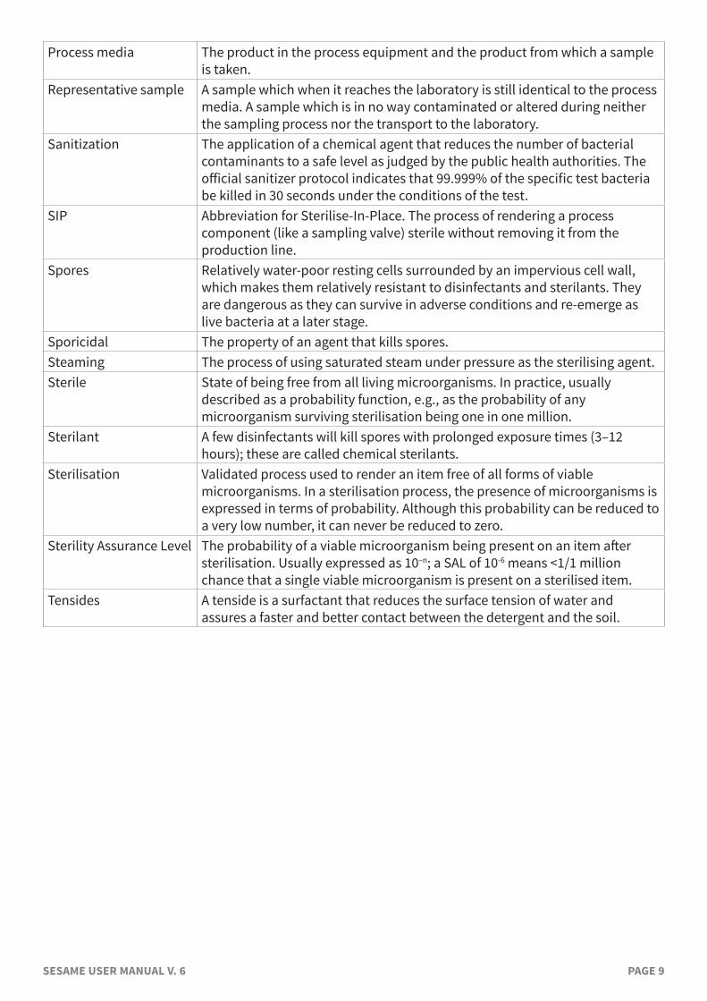
Process media The product in the process equipment and the product from which a sample is taken.
Representative sample A sample which when it reaches the laboratory is still identical to the process media. A sample which is in no way contaminated or altered during neither the sampling process nor the transport to the laboratory.
Sanitization The application of a chemical agent that reduces the number of bacterial contaminants to a safe level as judged by the public health authorities. The official sanitizer protocol indicates that 99.999% of the specific test bacteria be killed in 30 seconds under the conditions of the test.
SIP Abbreviation for Sterilise-In-Place. The process of rendering a process component (like a sampling valve) sterile without removing it from the production line.
Spores Relatively water-poor resting cells surrounded by an impervious cell wall, which makes them relatively resistant to disinfectants and sterilants. They are dangerous as they can survive in adverse conditions and re-emerge as live bacteria at a later stage.
Sporicidal The property of an agent that kills spores.Steaming The process of using saturated steam under pressure as the sterilising agent.Sterile State of being free from all living microorganisms. In practice, usually
described as a probability function, e.g., as the probability of any microorganism surviving sterilisation being one in one million.
Sterilant A few disinfectants will kill spores with prolonged exposure times (3–12 hours); these are called chemical sterilants.
Sterilisation Validated process used to render an item free of all forms of viable microorganisms. In a sterilisation process, the presence of microorganisms is expressed in terms of probability. Although this probability can be reduced to a very low number, it can never be reduced to zero.
Sterility Assurance Level The probability of a viable microorganism being present on an item after sterilisation. Usually expressed as 10–n; a SAL of 10-6 means <1/1 million chance that a single viable microorganism is present on a sterilised item.
Tensides A tenside is a surfactant that reduces the surface tension of water and assures a faster and better contact between the detergent and the soil.
SESAME USER MANUAL V. 6 PAGE 10
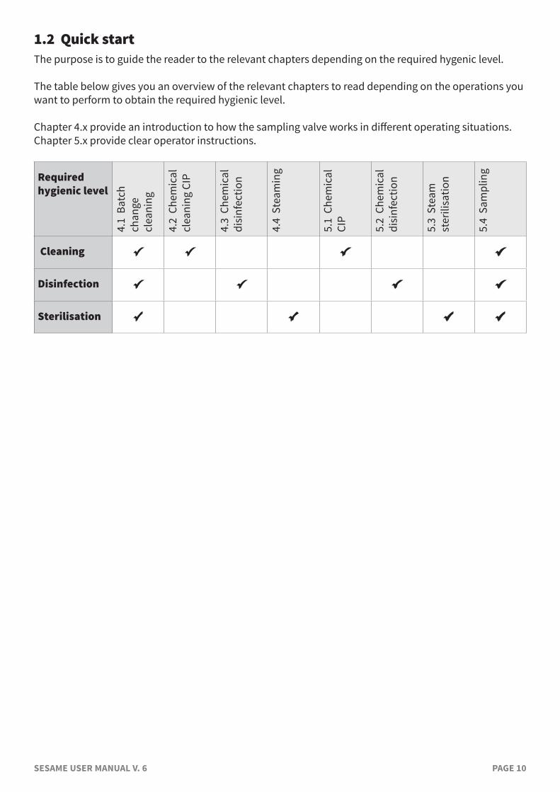
1.2 Quick startThe purpose is to guide the reader to the relevant chapters depending on the required hygenic level.
The table below gives you an overview of the relevant chapters to read depending on the operations you want to perform to obtain the required hygienic level.
Chapter 4.x provide an introduction to how the sampling valve works in different operating situations.Chapter 5.x provide clear operator instructions.
Required hygienic level
4.1
Bat
ch
chan
ge
clea
ning
4.2
Che
mic
al
clea
ning
CIP
4.3
Che
mic
al
disi
nfec
tion
4.4
Ste
amin
g
5.1
Che
mic
al
CIP
5.2
Che
mic
al
disi
nfec
tion
5.3
Ste
am
ster
ilisa
tion
5.4
Sam
plin
g
Cleaning
Disinfection
Sterilisation
SESAME USER MANUAL V. 6 PAGE 11
2. CLEANING – DISINFECTION – STERILISATION This chapter gives introduction to the concepts of cleaning, disinfecting and sterilizing process equipment in general, but with focus on sampling valves.
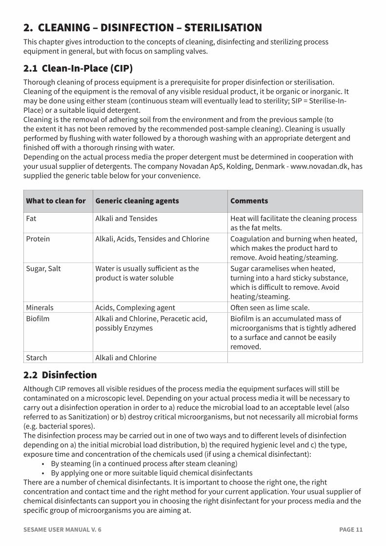
2.1 Clean-In-Place (CIP)Thorough cleaning of process equipment is a prerequisite for proper disinfection or sterilisation. Cleaning of the equipment is the removal of any visible residual product, it be organic or inorganic. It may be done using either steam (continuous steam will eventually lead to sterility; SIP = Sterilise-In-Place) or a suitable liquid detergent.Cleaning is the removal of adhering soil from the environment and from the previous sample (to the extent it has not been removed by the recommended post-sample cleaning). Cleaning is usually performed by flushing with water followed by a thorough washing with an appropriate detergent and finished off with a thorough rinsing with water.Depending on the actual process media the proper detergent must be determined in cooperation with your usual supplier of detergents. The company Novadan ApS, Kolding, Denmark - www.novadan.dk, has supplied the generic table below for your convenience.
What to clean for Generic cleaning agents Comments
Fat Alkali and Tensides Heat will facilitate the cleaning process as the fat melts.
Protein Alkali, Acids, Tensides and Chlorine Coagulation and burning when heated, which makes the product hard to remove. Avoid heating/steaming.
Sugar, Salt Water is usually sufficient as the product is water soluble
Sugar caramelises when heated, turning into a hard sticky substance, which is difficult to remove. Avoid heating/steaming.
Minerals Acids, Complexing agent Often seen as lime scale.Biofilm Alkali and Chlorine, Peracetic acid,
possibly EnzymesBiofilm is an accumulated mass of microorganisms that is tightly adhered to a surface and cannot be easily removed.
Starch Alkali and Chlorine
2.2 DisinfectionAlthough CIP removes all visible residues of the process media the equipment surfaces will still be contaminated on a microscopic level. Depending on your actual process media it will be necessary to carry out a disinfection operation in order to a) reduce the microbial load to an acceptable level (also referred to as Sanitization) or b) destroy critical microorganisms, but not necessarily all microbial forms (e.g. bacterial spores).The disinfection process may be carried out in one of two ways and to different levels of disinfection depending on a) the initial microbial load distribution, b) the required hygienic level and c) the type, exposure time and concentration of the chemicals used (if using a chemical disinfectant):
• By steaming (in a continued process after steam cleaning)• By applying one or more suitable liquid chemical disinfectants
There are a number of chemical disinfectants. It is important to choose the right one, the right concentration and contact time and the right method for your current application. Your usual supplier of chemical disinfectants can support you in choosing the right disinfectant for your process media and the specific group of microorganisms you are aiming at.
SESAME USER MANUAL V. 6 PAGE 12
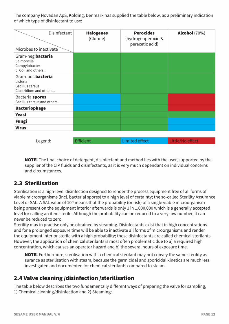
The company Novadan ApS, Kolding, Denmark has supplied the table below, as a preliminary indication of which type of disinfectant to use:
Disinfectant
Microbes to inactivate
Halogenes(Clorine)
Peroxides(hydrogenperoxid &
peracetic acid)
Alcohol (70%)
Gram-neg bacteriaSalmonellaCampylobacterE. Coli and others...
Gram-pos bacteriaListeriaBacillus cereusClostridium and others...
Bacteria sporesBacillus cereus and others...
BacteriophageYeastFungiVirus
Legend: Efficient Limited effect Little/No effect
NOTE! The final choice of detergent, disinfectant and method lies with the user, supported by the supplier of the CIP fluids and disinfectants, as it is very much dependant on individual concerns and circumstances.
2.3 SterilisationSterilisation is a high-level disinfection designed to render the process equipment free of all forms of viable microorganisms (incl. bacterial spores) to a high level of certainty; the so-called Sterility Assurance Level or SAL. A SAL value of 10-6 means that the probability (or risk) of a single viable microorganism being present on the equipment interior afterwards is only 1 in 1,000,000 which is a generally accepted level for calling an item sterile. Although the probability can be reduced to a very low number, it can never be reduced to zero.Sterility may in practise only be obtained by steaming. Disinfectants exist that in high concentrations and for a prolonged exposure time will be able to inactivate all forms of microorganisms and render the equipment interior sterile with a high probability; these disinfectants are called chemical sterilants. However, the application of chemical sterilants is most often problematic due to a) a required high concentration, which causes an operator hazard and b) the several hours of exposure time.
NOTE! Furthermore, sterilisation with a chemical sterilant may not convey the same sterility as-surance as sterilisation with steam, because the germicidal and sporicidal kinetics are much less investigated and documented for chemical sterilants compared to steam.
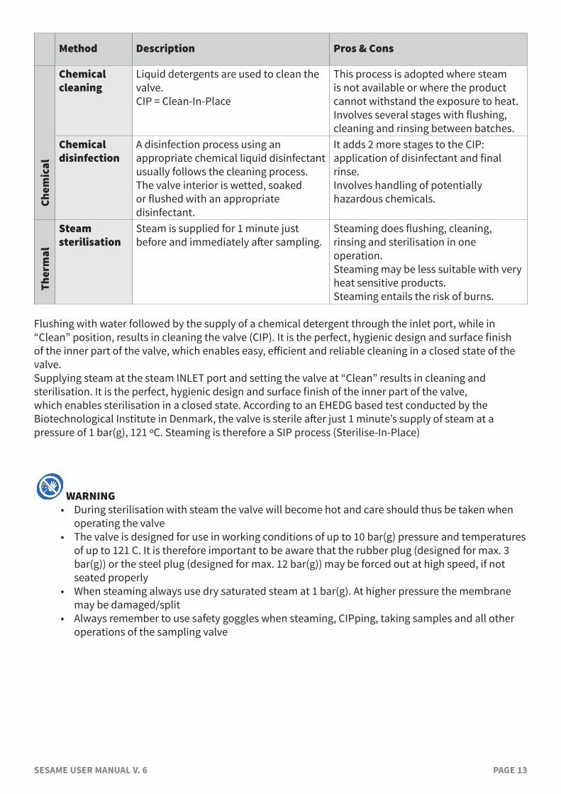
2.4 Valve cleaning /disinfection /sterilisation The table below describes the two fundamentally different ways of preparing the valve for sampling, 1) Chemical cleaning/disinfection and 2) Steaming:
SESAME USER MANUAL V. 6 PAGE 13
Method Description Pros & ConsCh
emic
al
Chemical cleaning
Liquid detergents are used to clean the valve.CIP = Clean-In-Place
This process is adopted where steam is not available or where the product cannot withstand the exposure to heat.Involves several stages with flushing, cleaning and rinsing between batches.
Chemical disinfection
A disinfection process using an appropriate chemical liquid disinfectant usually follows the cleaning process.The valve interior is wetted, soaked or flushed with an appropriate disinfectant.
It adds 2 more stages to the CIP: application of disinfectant and final rinse.Involves handling of potentially hazardous chemicals.
Ther
mal
Steam sterilisation
Steam is supplied for 1 minute just before and immediately after sampling.
Steaming does flushing, cleaning, rinsing and sterilisation in one operation.Steaming may be less suitable with very heat sensitive products.Steaming entails the risk of burns.
Flushing with water followed by the supply of a chemical detergent through the inlet port, while in “Clean” position, results in cleaning the valve (CIP). It is the perfect, hygienic design and surface finish of the inner part of the valve, which enables easy, efficient and reliable cleaning in a closed state of the valve. Supplying steam at the steam INLET port and setting the valve at “Clean” results in cleaning and sterilisation. It is the perfect, hygienic design and surface finish of the inner part of the valve, which enables sterilisation in a closed state. According to an EHEDG based test conducted by the Biotechnological Institute in Denmark, the valve is sterile after just 1 minute’s supply of steam at a pressure of 1 bar(g), 121 ºC. Steaming is therefore a SIP process (Sterilise-In-Place)
WARNING• During sterilisation with steam the valve will become hot and care should thus be taken when
operating the valve• The valve is designed for use in working conditions of up to 10 bar(g) pressure and temperatures
of up to 121 C. It is therefore important to be aware that the rubber plug (designed for max. 3 bar(g)) or the steel plug (designed for max. 12 bar(g)) may be forced out at high speed, if not seated properly
• When steaming always use dry saturated steam at 1 bar(g). At higher pressure the membrane may be damaged/split
• Always remember to use safety goggles when steaming, CIPping, taking samples and all other operations of the sampling valve
SESAME USER MANUAL V. 6 PAGE 14
3. VALVE DESIGN AND FUNCTIONINGThe valve is intended for regularly taking representative samples in the production process. The valve is therefore designed such that effective cleaning, disinfection/sterilisation and sampling can be carried out regularly without interrupting the production process.
NOTE! The membrane has a tripple function: it serves as a dynamic seal towards the process side, it acts as a dynamic seal to activate cleaning/steaming and it constitutes a hygienic static sealing against the valve head.
3.1 Valve body configurationsValve bodies may be welded to the process equipment or connected by means of one of the standard connector systems.Welding configurations encompass the following options: • Tank welding, ø38 mm • Pipe welding, 25 mmConnector configurations encompass the following options: • Varivent, ø50 mm • Varivent, ø68 mm • 1/2” Mini Clamp (always use a gasket; not included in valve body delivery)
• Clamp 1”; Clamp1”, NA-connect, DIN/ASME (always use a gasket; not included in valve body delivery)
• Clamp 2”; Clamp2”, NA-connect, DIN/ASME (always use a gasket; not included in valve body delivery)
• Union, DIN 11851 • Ingold 40 mm port length • Ingold 52 mm port lengthThe inlet and outlet ports are available in the following configurations: • Hose Piece (Keofitt Quick Coupling) • Mini Tri-clamp (always use a gasket; not included in valve body delivery)
• Thread M16x1.5 • Welding ends (to weld steel tubing on)
NOTE: All welding/connector options are available with Hose Piece ports. For the other port configurations only some combinations are standard; but all non-standard combinations are likely to be available “On request”.
NOTE: Ingold bodies are only available with Mini-clamp connectors.All valve bodies with their various ports are machined in one piece of steel, thus avoiding all crevices and fissures from screwed or welded parts.
For further information please consult www.keofitt.dk.
3.2 Valve head configurationsValve heads come in the following configurations: • Turn knob (type H) • Lever handle (type Q) • Pneumatic (type N)All configurations, except the INGOLD variant, may be delivered with PTFE, EPDM or Silicone membranes.INGOLD valve heads are only available with PTFE membranes.For further information please consult www.keofitt.dk.
SESAME USER MANUAL V. 6 PAGE 15
3.3 Valve surfaces and roughness certificateAll Keofitt valves are electro polished internally using a proprietary technique and each valve has its individual certificate (Test Report) stating the results of 3 test measurements of the surface roughness in each of the 2 ports, in the valve chamber and on the outer body surface with product contact.For obvious reasons, the surface properties of the internal product contact areas of a sampling valve are much more important from a hygiene perspective than any shiny outside surface appearance. Therefore, Keofitt has developed a unique electrode configuration to assure during manufacturing that the internal surfaces in particular are properly electro polished.
3.4 Rubber caps and steel capsThe purpose of the cap is to protect the valve chamber from the environment between sampling. Steel caps (part no. 800061) may be used instead of rubber caps and will provide a stronger mechanical fixation to the hose piece and thus be operational under higher pressure and temperature. Furthermore, the steel plugs may be autoclaved.For further information please consult www.keofitt.dk.
3.5 Sampling coilWhen sampling beer, the rapid pressure drop from inside the tank (CO2 pressure of 2-3 bar) to the open sample recipient at ambient pressure causes excessive foaming, even when opening the valve very slowly and very little. This phenomenon may be alleviated connecting a sampling coil (part no. 800058) between the sampling valve and the sample recipient. A sampling coil provides a more gradual pressure drop as the sample flows through the full length of the coil, approx. 1 m.For further information please consult www.keofitt.dk.
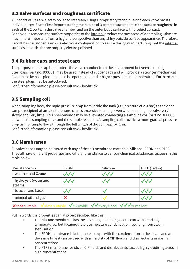
3.6 MembranesAll valve heads may be delivered with any of these 3 membrane materials: Silicone, EPDM and PTFE. They all have different properties and different resistance to various chemical substances, as seen in the table below.
Resistance to - EPDM Silicone PTFE (Teflon)- weather and Ozone
- hydrolysis (water and steam)- to acids and bases - mineral oil and gas X
X=not suitable =less suitable =Suitable =Very Good =Excellent
Put in words the properties can also be described like this: • The Silicone membrane has the advantage that it in general can withstand high
temperatures, but it cannot tolerate moisture condensation resulting from steam sterilisation
• The EPDM membrane is better able to cope with the condensation in the steam and at the same time it can be used with a majority of CIP fluids and disinfectants in normal concentrations
• The PTFE membrane resists all CIP fluids and disinfectants except highly oxidising acids in high concentrations
SESAME USER MANUAL V. 6 PAGE 16
Membranes in rubber materials like EPDM and Silicone are fully interchangeable. This means that you may change from for instance Silicone to EPDM, if required.However, valve heads with PTFE membranes are designed differently from the others. As PTFE is a stiff material with no elastic properties, it cannot be stretched. Therefore, it is made with a bellow to allow for the valve movement.
NOTE! The membrane functions as a dynamic seal in the valve seat and the CIP/steam seat, as well as a hygienic static sealing against the valve head.
NOTE! The choice of a membrane material for a given application lies with the customer, as it
very much depends on production parameters specific to the customer, such as temprature, chemical composition of the customer’s process medium etc. Consult KEOFITT membrane data sheets and relevant chemical resistance charts in order to choose an appropriate membrane material.
3.7 Parts and AccessoriesKeofitt provide a huge number of spare parts and accessories to the SESAME valves. These include accessories like: • Barbed fittings and tube welding fittings for tubes and hoses • Adaptors between Tri-clamp, Mini Tri-clamp and Hose Piece (Quick Coupling) • Spike Bag holders and Spikes • Fitted PTFE tubing for Quick Coupling and Tri-clamp • Any length of PTFE tube • Clamps for Tri-clamp connections • Hypodermic needlesand spare parts like: • O-rings and gaskets • Membranes • Steam burners/click on • Sampling Bags • Bottle headsFor further information please refer to www.keofitt.dk
3.8 Pressure and vacuumPressure ratings:All SESAME valves feature a spring to provide the closing force against the valve seat. The spring is dimensioned such that all valves must pass a pressure test up to 14 bar. At some tank pressure above 10 bar the spring will give way and the valve will leak.A nominal max. constant pressure of 10 bar allow sufficient tolerance to cater for the most common pressure peaks in a process line.
Vacuum ratings:On installations where vacuum may occur temporarily, rubber membranes (EPDM, Silicone) are at risk of being sucked hard into the valve seat, whereby the valve might not open properly. However, the additional (closing) force from the vacuum (corresponding to max. -1 bar(g) or 0 bar(abs)) is rather small (10%) compared the force exerted by the spring (corresponding to at least 10 bar(g)), so there is no risk of damaging the membrane as long as the vacuum is only present when the valve is closed.Besides, attempting to open a sampling valve under vacuum makes no sense, since nothing will flow out, so the incident is rather improbable.Rubber membranes will seal perfectly well against vacuum, when the valve is kept closed.
SESAME USER MANUAL V. 6 PAGE 17
WARNING:• When opening the valve while the process side is under vaccum there is a risk that the
membrane may be sucked past the valve seat and into the valve opening, which could cause the membrane to be damaged.
• On installations where vacuum will occur, PTFE membranes don’t have the risk of being sucked into the valve seat, but as it is a harder and less flexible material a complete tightness against the ambient air may not be secured.
SESAME USER MANUAL V. 6 PAGE 18
4. EVERYDAY USE OF THE VALVEThis chapter gives an introduction to how the sampling valve works in different operating conditions, such as the cleaning of the entire production line before starting a new batch (chapter 4.1) and the cleaning of the valve between each sample during the batch production (chapters 4.2-4.4) For specific operator instructions please refer to the chapter 5. “VALVE OPERATIONS”.
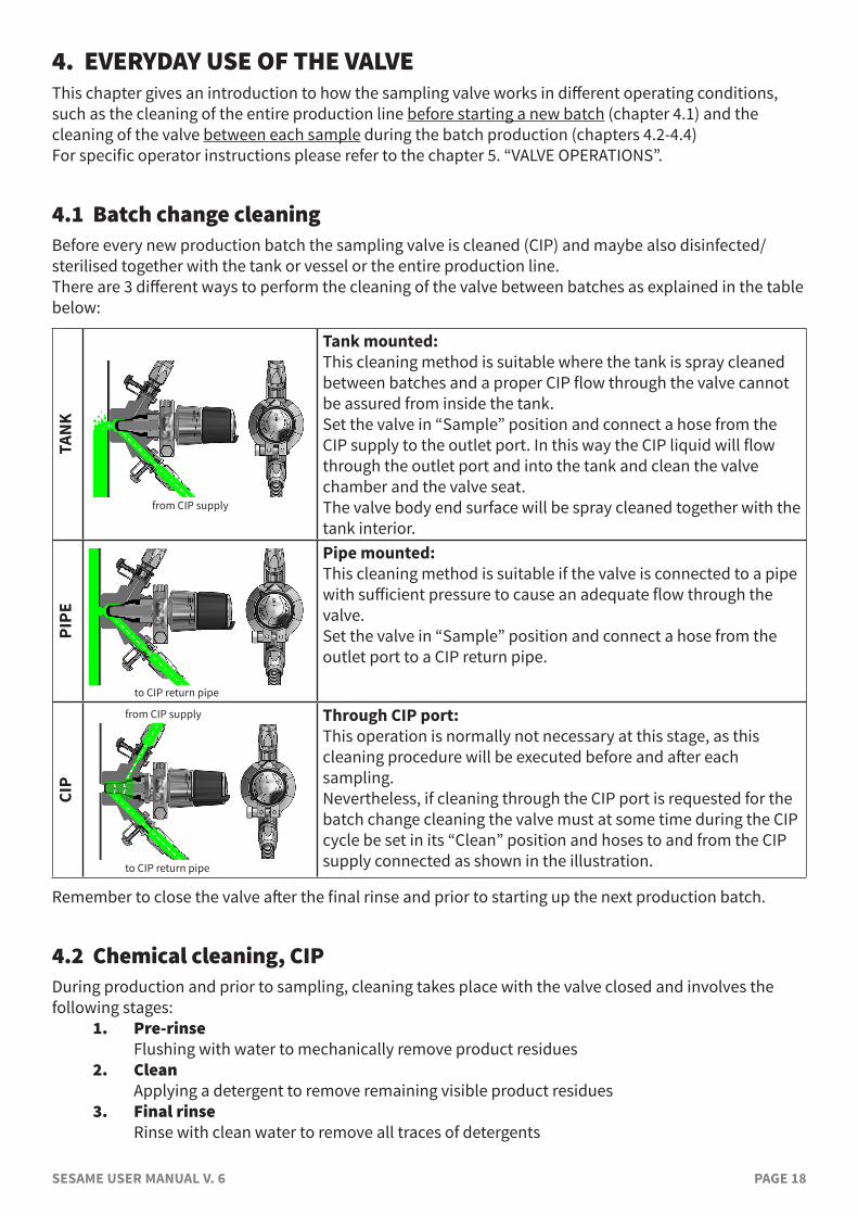
4.1 Batch change cleaningBefore every new production batch the sampling valve is cleaned (CIP) and maybe also disinfected/sterilised together with the tank or vessel or the entire production line.There are 3 different ways to perform the cleaning of the valve between batches as explained in the table below:
TAN
K
from CIP supply
Tank mounted:This cleaning method is suitable where the tank is spray cleaned between batches and a proper CIP flow through the valve cannot be assured from inside the tank.Set the valve in “Sample” position and connect a hose from the CIP supply to the outlet port. In this way the CIP liquid will flow through the outlet port and into the tank and clean the valve chamber and the valve seat.The valve body end surface will be spray cleaned together with the tank interior.
PIPE
to CIP return pipe
Pipe mounted:This cleaning method is suitable if the valve is connected to a pipe with sufficient pressure to cause an adequate flow through the valve.Set the valve in “Sample” position and connect a hose from the outlet port to a CIP return pipe.
CIP
from CIP supply
to CIP return pipe
Through CIP port:This operation is normally not necessary at this stage, as this cleaning procedure will be executed before and after each sampling.Nevertheless, if cleaning through the CIP port is requested for the batch change cleaning the valve must at some time during the CIP cycle be set in its “Clean” position and hoses to and from the CIP supply connected as shown in the illustration.
Remember to close the valve after the final rinse and prior to starting up the next production batch.
4.2 Chemical cleaning, CIPDuring production and prior to sampling, cleaning takes place with the valve closed and involves the following stages:
1. Pre-rinse Flushing with water to mechanically remove product residues
2. Clean Applying a detergent to remove remaining visible product residues
3. Final rinse Rinse with clean water to remove all traces of detergents
SESAME USER MANUAL V. 6 PAGE 19
Usually this procedure is followed by disinfection (see below), but for some application CIP might be sufficient. It depends on your (microbiological) requirements, the detergents applied and the process media to clean for. Consult your supplier of CIP fluids.In some cases where the process media is for instance water, CIP might not even be necessary and you may go directly to disinfection.
4.3 Chemical disinfectionDisinfection takes place with the valve closed and involves the following stages of which the first 3 are identical to CIP:
1. Pre-rinse Flushing with water to mechanically remove product residues
2. Clean Applying a detergent to remove remaining visible product residues
3. Intermediate rinse Rinse with clean water to remove all traces of detergents
4. Disinfection Apply an appropriate disinfectant targeting one or more or all microorganisms
5. Final rinse Rinse with cleaned water to remove all traces of the disinfectant
4.4 Steam sterilisationSteaming has the advantage that it does flushing, cleaning and sterilisation in one operation. However the heat from the steam will cause sugary substances to caramelise and substances containing protein to coagulate and burn; see chapter 2.1. In this case you must disconnect any fixed steam supply in order to flush the valve with an appropriate fluid prior to the post-sampling steaming.If steaming is the preferred procedure, but no steam is installed near the sampling point, an option is to use a portable steam generator. Keofitt supplies an adaptor for a Kärcher steam generator, as well as other mobile steam supply solution. The steaming process with a Keofitt sampling valve has been validated to obtain sterility after 1 minute of steaming at 121° C (1 bar(g)). Documentation is available at the Keofitt Online Service Center on www.keofitt.dk.

SESAME USER MANUAL V. 6 PAGE 20
5. VALVE OPERATIONSThis chapter provides clear instructions on how to operate the sampling valve in different situations.Before sampling the valve must be cleaned followed by disinfection or sterilisation, depending on your requirements. NOTE! For the initial cleaning before a new batch please refer to chapter 4.1 “Batch change
cleaning” and integrate the valve cleaning in your standard CIP procedure.
IMPORTANT• All illustrations show a sampling valve with Keofitt hose piece connections. All instructions
also apply to valve versions with clamp connections; only make sure to use the corresponding fittings.
• All illustrations show a sampling valve with a turn knob. However the instructions also apply to pneumatic valves and valves with a handle. Valve equipped with type N or type Q heads.
There are 3 means of operating the SESAME sampling valve:1. Turn knob2. Lever handle3. PneumaticEach of them may activate both “Cleaning” and “Sampling”Activating for Cleaning is explained in the table below and relevant for chapters 5.1 – 5.3.Activating for Sampling is explained in a table in chapter 5.4.
Valve head Illustration Instructions to cleanTurn knob Type H
To clean the valve, turn the turn knob anticlockwise from OFF into the CLEAN marking. To stop cleaning turn the turn knob clockwise back into the OFF position
Lever handle Type Q
Enter the specific SESAME lever handle into the groove of the black turn knob. Turn the turn knob with the handle into the Cleaning position. Move the tip of the handle slowly away from the valve head and into a position co-axial with the valve head; the valve is now fully open. For closing, there are 2 options: 1. Continue the movement of the handle another 90 degrees; the valve is now closed, and the lever handle locked in position. 2. Reverse the initial movement of the handle. The valve is now closed, and you may remove the lever handle to avoid it falling out. Removing the lever handle after sampling impedes unintentional opening of the valve.
1
2
3
SESAME USER MANUAL V. 6 PAGE 21
Pneumatic Type N
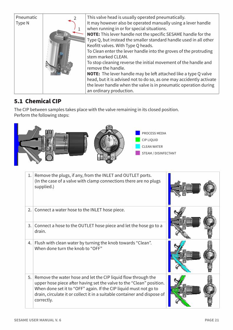
This valve head is usually operated pneumatically.It may however also be operated manually using a lever handle when running in or for special situations.NOTE: This lever handle not the specific SESAME handle for the Type Q, but instead the smaller standard handle used in all other Keofitt valves. With Type Q heads.To Clean enter the lever handle into the groves of the protruding stem marked CLEAN.To stop cleaning reverse the initial movement of the handle and remove the handle.NOTE: The lever handle may be left attached like a type Q valve head, but it is advised not to do so, as one may accidently activate the lever handle when the valve is in pneumatic operation during an ordinary production.
5.1 Chemical CIPThe CIP between samples takes place with the valve remaining in its closed position.Perform the following steps:
n PROCESS MEDIA
n CIP LIQUID
n CLEAN WATER
n STEAM / DISINFECTANT
1. Remove the plugs, if any, from the INLET and OUTLET ports.(In the case of a valve with clamp connections there are no plugs supplied.)
2. Connect a water hose to the INLET hose piece.
3. Connect a hose to the OUTLET hose piece and let the hose go to a drain.
4. Flush with clean water by turning the knob towards “Clean”.When done turn the knob to “OFF”
5. Remove the water hose and let the CIP liquid flow through the upper hose piece after having set the valve to the “Clean” position.When done set it to “OFF” again. If the CIP liquid must not go to drain, circulate it or collect it in a suitable container and dispose of correctly.
1
2
SESAME USER MANUAL V. 6 PAGE 22
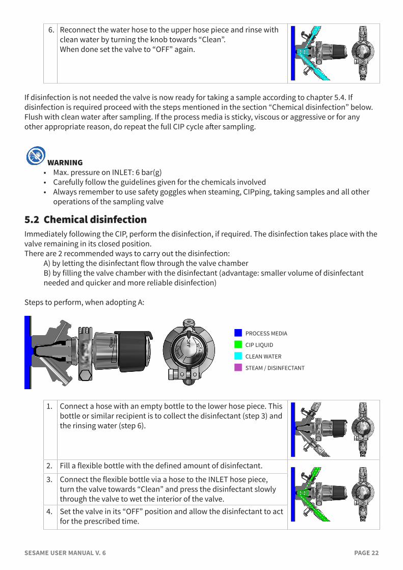
6. Reconnect the water hose to the upper hose piece and rinse with clean water by turning the knob towards “Clean”.When done set the valve to “OFF” again.
If disinfection is not needed the valve is now ready for taking a sample according to chapter 5.4. If disinfection is required proceed with the steps mentioned in the section “Chemical disinfection” below.Flush with clean water after sampling. If the process media is sticky, viscous or aggressive or for any other appropriate reason, do repeat the full CIP cycle after sampling.
WARNING• Max. pressure on INLET: 6 bar(g)• Carefully follow the guidelines given for the chemicals involved • Always remember to use safety goggles when steaming, CIPping, taking samples and all other
operations of the sampling valve
5.2 Chemical disinfectionImmediately following the CIP, perform the disinfection, if required. The disinfection takes place with the valve remaining in its closed position.There are 2 recommended ways to carry out the disinfection: A) by letting the disinfectant flow through the valve chamber B) by filling the valve chamber with the disinfectant (advantage: smaller volume of disinfectant
needed and quicker and more reliable disinfection)
Steps to perform, when adopting A:
n PROCESS MEDIA
n CIP LIQUID
n CLEAN WATER
n STEAM / DISINFECTANT
1. Connect a hose with an empty bottle to the lower hose piece. This bottle or similar recipient is to collect the disinfectant (step 3) and the rinsing water (step 6).
2. Fill a flexible bottle with the defined amount of disinfectant.
3. Connect the flexible bottle via a hose to the INLET hose piece, turn the valve towards “Clean” and press the disinfectant slowly through the valve to wet the interior of the valve.
4. Set the valve in its “OFF” position and allow the disinfectant to act for the prescribed time.
SESAME USER MANUAL V. 6 PAGE 23
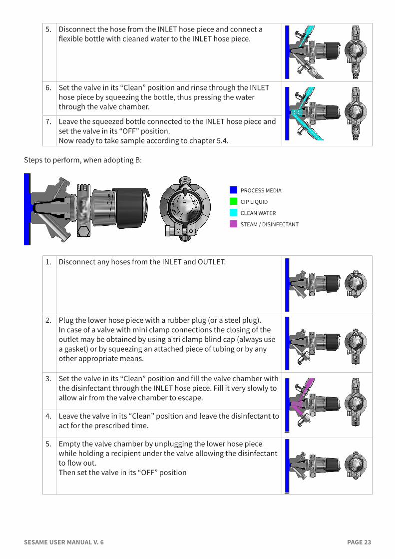
5. Disconnect the hose from the INLET hose piece and connect a flexible bottle with cleaned water to the INLET hose piece.
6. Set the valve in its “Clean” position and rinse through the INLET hose piece by squeezing the bottle, thus pressing the water through the valve chamber.
7. Leave the squeezed bottle connected to the INLET hose piece and set the valve in its “OFF” position.Now ready to take sample according to chapter 5.4.
Steps to perform, when adopting B:
n PROCESS MEDIA
n CIP LIQUID
n CLEAN WATER
n STEAM / DISINFECTANT
1. Disconnect any hoses from the INLET and OUTLET.
2. Plug the lower hose piece with a rubber plug (or a steel plug).In case of a valve with mini clamp connections the closing of the outlet may be obtained by using a tri clamp blind cap (always use a gasket) or by squeezing an attached piece of tubing or by any other appropriate means.
3. Set the valve in its “Clean” position and fill the valve chamber with the disinfectant through the INLET hose piece. Fill it very slowly to allow air from the valve chamber to escape.
4. Leave the valve in its “Clean” position and leave the disinfectant to act for the prescribed time.
5. Empty the valve chamber by unplugging the lower hose piece while holding a recipient under the valve allowing the disinfectant to flow out.Then set the valve in its “OFF” position
SESAME USER MANUAL V. 6 PAGE 24
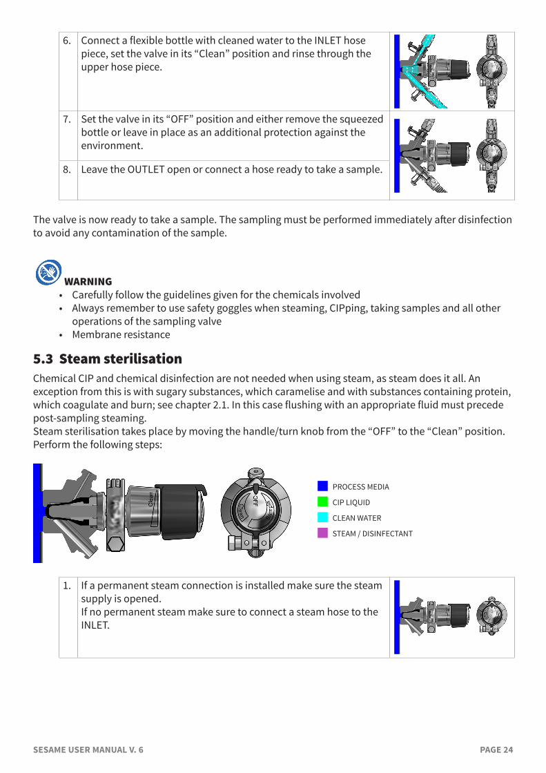
6. Connect a flexible bottle with cleaned water to the INLET hose piece, set the valve in its “Clean” position and rinse through the upper hose piece.
7. Set the valve in its “OFF” position and either remove the squeezed bottle or leave in place as an additional protection against the environment.
8. Leave the OUTLET open or connect a hose ready to take a sample.
The valve is now ready to take a sample. The sampling must be performed immediately after disinfection to avoid any contamination of the sample.
WARNING• Carefully follow the guidelines given for the chemicals involved • Always remember to use safety goggles when steaming, CIPping, taking samples and all other
operations of the sampling valve• Membrane resistance
5.3 Steam sterilisationChemical CIP and chemical disinfection are not needed when using steam, as steam does it all. An exception from this is with sugary substances, which caramelise and with substances containing protein, which coagulate and burn; see chapter 2.1. In this case flushing with an appropriate fluid must precede post-sampling steaming.Steam sterilisation takes place by moving the handle/turn knob from the “OFF” to the “Clean” position. Perform the following steps:
n PROCESS MEDIA
n CIP LIQUID
n CLEAN WATER
n STEAM / DISINFECTANT
1. If a permanent steam connection is installed make sure the steam supply is opened.If no permanent steam make sure to connect a steam hose to the INLET.
SESAME USER MANUAL V. 6 PAGE 25
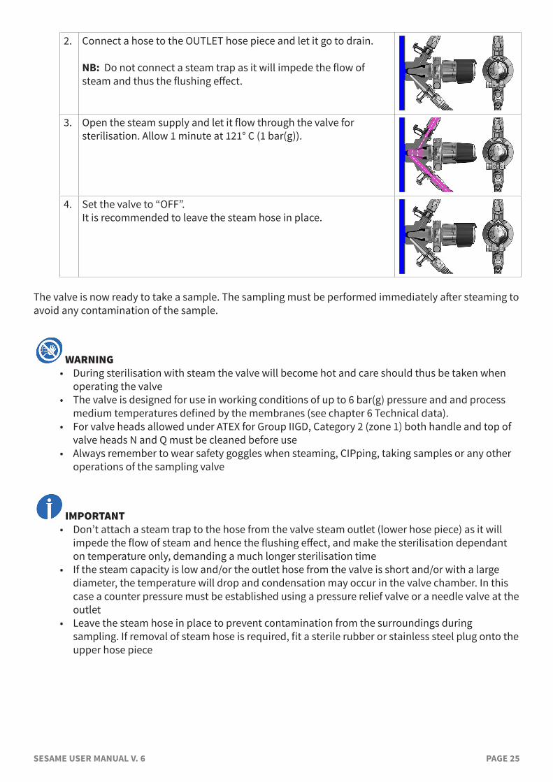
2. Connect a hose to the OUTLET hose piece and let it go to drain.
NB: Do not connect a steam trap as it will impede the flow of steam and thus the flushing effect.
3. Open the steam supply and let it flow through the valve for sterilisation. Allow 1 minute at 121° C (1 bar(g)).
4. Set the valve to “OFF”.It is recommended to leave the steam hose in place.
The valve is now ready to take a sample. The sampling must be performed immediately after steaming to avoid any contamination of the sample.
WARNING• During sterilisation with steam the valve will become hot and care should thus be taken when
operating the valve• The valve is designed for use in working conditions of up to 6 bar(g) pressure and and process
medium temperatures defined by the membranes (see chapter 6 Technical data). • For valve heads allowed under ATEX for Group IIGD, Category 2 (zone 1) both handle and top of
valve heads N and Q must be cleaned before use• Always remember to wear safety goggles when steaming, CIPping, taking samples or any other
operations of the sampling valve
IMPORTANT• Don’t attach a steam trap to the hose from the valve steam outlet (lower hose piece) as it will
impede the flow of steam and hence the flushing effect, and make the sterilisation dependant on temperature only, demanding a much longer sterilisation time
• If the steam capacity is low and/or the outlet hose from the valve is short and/or with a large diameter, the temperature will drop and condensation may occur in the valve chamber. In this case a counter pressure must be established using a pressure relief valve or a needle valve at the outlet
• Leave the steam hose in place to prevent contamination from the surroundings during sampling. If removal of steam hose is required, fit a sterile rubber or stainless steel plug onto the upper hose piece
SESAME USER MANUAL V. 6 PAGE 26
5.4 SamplingPrepare a recipient for your sample. For aseptic sampling use steam and a Keofitt Aseptic Sampling Bag (available in different sizes; please see datasheet on www.keofitt.dk). Leave the steam hose in place to prevent contamination from the surroundings during sampling.For all other sampling use a Keofitt Sterile Sampling Bag or a Spike Bag, which provides a closed flow path for your sample protecting it from the surroundings. Alternatives are bottles with a screw cap, jars or any other available container.
There are 3 means of operating the SESAME sampling valve:1. Turn knob2. Lever handle3. PneumaticEach of them may activate both “Cleaning” and “Sampling”Activating for Cleaning is explained in the table in chapter 5.Activating for Sampling is explained in the table in below chapter 5.4.
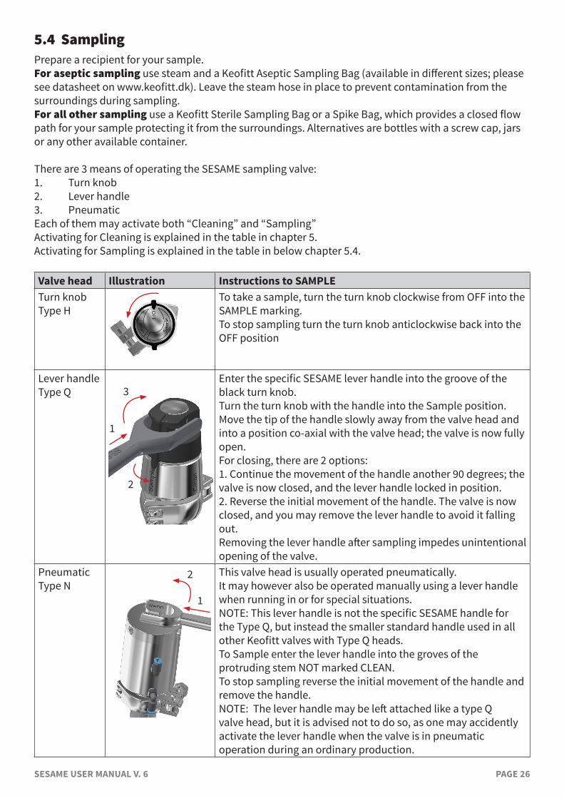
Valve head Illustration Instructions to SAMPLETurn knob Type H
To take a sample, turn the turn knob clockwise from OFF into the SAMPLE marking. To stop sampling turn the turn knob anticlockwise back into the OFF position
Lever handle Type Q
Enter the specific SESAME lever handle into the groove of the black turn knob. Turn the turn knob with the handle into the Sample position. Move the tip of the handle slowly away from the valve head and into a position co-axial with the valve head; the valve is now fully open. For closing, there are 2 options: 1. Continue the movement of the handle another 90 degrees; the valve is now closed, and the lever handle locked in position. 2. Reverse the initial movement of the handle. The valve is now closed, and you may remove the lever handle to avoid it falling out. Removing the lever handle after sampling impedes unintentional opening of the valve.
Pneumatic Type N
This valve head is usually operated pneumatically. It may however also be operated manually using a lever handle when running in or for special situations. NOTE: This lever handle is not the specific SESAME handle for the Type Q, but instead the smaller standard handle used in all other Keofitt valves with Type Q heads. To Sample enter the lever handle into the groves of the protruding stem NOT marked CLEAN. To stop sampling reverse the initial movement of the handle and remove the handle. NOTE: The lever handle may be left attached like a type Q valve head, but it is advised not to do so, as one may accidently activate the lever handle when the valve is in pneumatic operation during an ordinary production.
1
2
3
1
2
SESAME USER MANUAL V. 6 PAGE 27
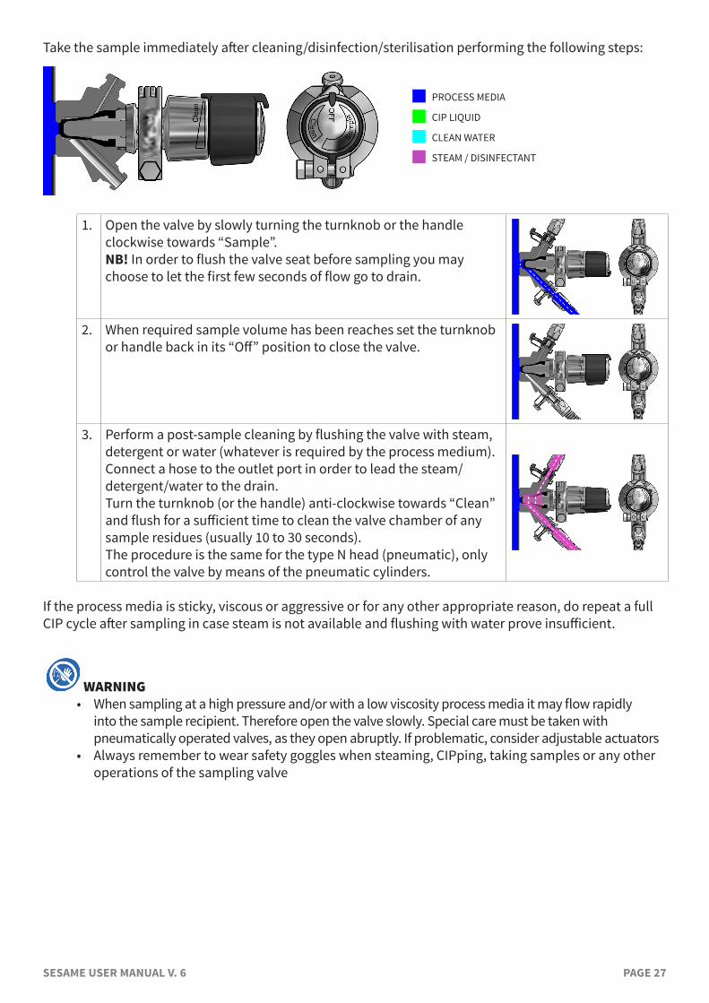
Take the sample immediately after cleaning/disinfection/sterilisation performing the following steps:
n PROCESS MEDIA
n CIP LIQUID
n CLEAN WATER
n STEAM / DISINFECTANT
1. Open the valve by slowly turning the turnknob or the handle clockwise towards “Sample”. NB! In order to flush the valve seat before sampling you may choose to let the first few seconds of flow go to drain.
2. When required sample volume has been reaches set the turnknob or handle back in its “Off” position to close the valve.
3. Perform a post-sample cleaning by flushing the valve with steam, detergent or water (whatever is required by the process medium). Connect a hose to the outlet port in order to lead the steam/detergent/water to the drain.Turn the turnknob (or the handle) anti-clockwise towards “Clean” and flush for a sufficient time to clean the valve chamber of any sample residues (usually 10 to 30 seconds).The procedure is the same for the type N head (pneumatic), only control the valve by means of the pneumatic cylinders.
If the process media is sticky, viscous or aggressive or for any other appropriate reason, do repeat a full CIP cycle after sampling in case steam is not available and flushing with water prove insufficient.
WARNING• When sampling at a high pressure and/or with a low viscosity process media it may flow rapidly
into the sample recipient. Therefore open the valve slowly. Special care must be taken with pneumatically operated valves, as they open abruptly. If problematic, consider adjustable actuators
• Always remember to wear safety goggles when steaming, CIPping, taking samples or any other operations of the sampling valve
SESAME USER MANUAL V. 6 PAGE 28
6. TECHNICAL DATA
6.1 MaterialValve body: AISI 316L (1.4435)Valve head: AISI 316L (1.4404)Membrane: Silicone (grey)
EPDM (black) PTFE (white)
6.2 Certificate3-A: Conforming to 3-A Sanitary Standards for 55-02 (Boot Seal-Type Valves)Valve body: 3.1*)
*A 6-digit code is marked on the valve body. This code refers to a 3.1 certificate which accompanies every consignment of valve bodies. The 3.1 certificate is available at the Keofitt Online Service Center on www.keofitt.dk. Click Certificates and then 3.1.
Membrane: Silicone acc. to FDA, 3-A; EC1935, EC2023, USP, BfR XV EPDM acc. to FDA, 3-A, EC1935, EC2023, USP Class VI PTFE acc. to EU10, EU1935, EU2023, FDA, USP Class VI
For more details please see the individual certificates.
6.3 Pressure (max.)Process pressure: 10 bar(g) / 145 psi(g) CIP/SIP: 6 bar(g) / 87 psi(g)Rubber plug: 3 bar(g) / 44 psi(g)Steel plug: 12 bar(g) / 218 psi(g)
6.4 TemperatureSteam: Sterilisation using dry, saturated steam at 121 C / 250 F and 1 bar(g). Dry,
saturated steam at temperatures up to 134 C /272 F and 2 bar(g) is possible, but might reduce the service life of the membrane.
Process medium: The acceptable operating temperature range for the process medium depends on the choice of membrane as follows:
• Silicone: 0 C to 130°C (32-265°F) • EPDM: 0 C to 130°C (32-265°F) • PTFE: 0 C to 150°C (32-300°F) Sub-zero Centigrade operation is possible with all membranes. Please consult your local distributorog KEOFITT if occation arises.
Ambient: The range of acceptable ambient temperatures is limited by the polymer turn knob and the pneumatic cylinder to -40 C to 80 C.
SESAME USER MANUAL V. 6 PAGE 29
6.5 Surface finishInternal: Electropolished
Ra<=0.5µm / 20µinch The mean and standard deviation are statictical valves measured for a given
production batch: Ra(mean) = 0.2µm / 8µinch
Ra(std.deviation) = 0.08µm / 3µinch Valves with internal electropolishing are identified by an E preceding the serial
number e.g. E12345678External: Electropolished
The surface roughness is measured for each valve at 3 critical places (the valve body process surface, the valve chamber and the outlet port). A serial number identifies each valve body. A specific surface roughness certificate is supplied with every valve. A general surface finish certificate copy is available on www.keofitt.dk
6.6 Viscosity:Viscosity range: 0-1000cP, with particles up to 3mm in diameter. Higher viscosity liquids may be sampled, only will the sampling take longer.
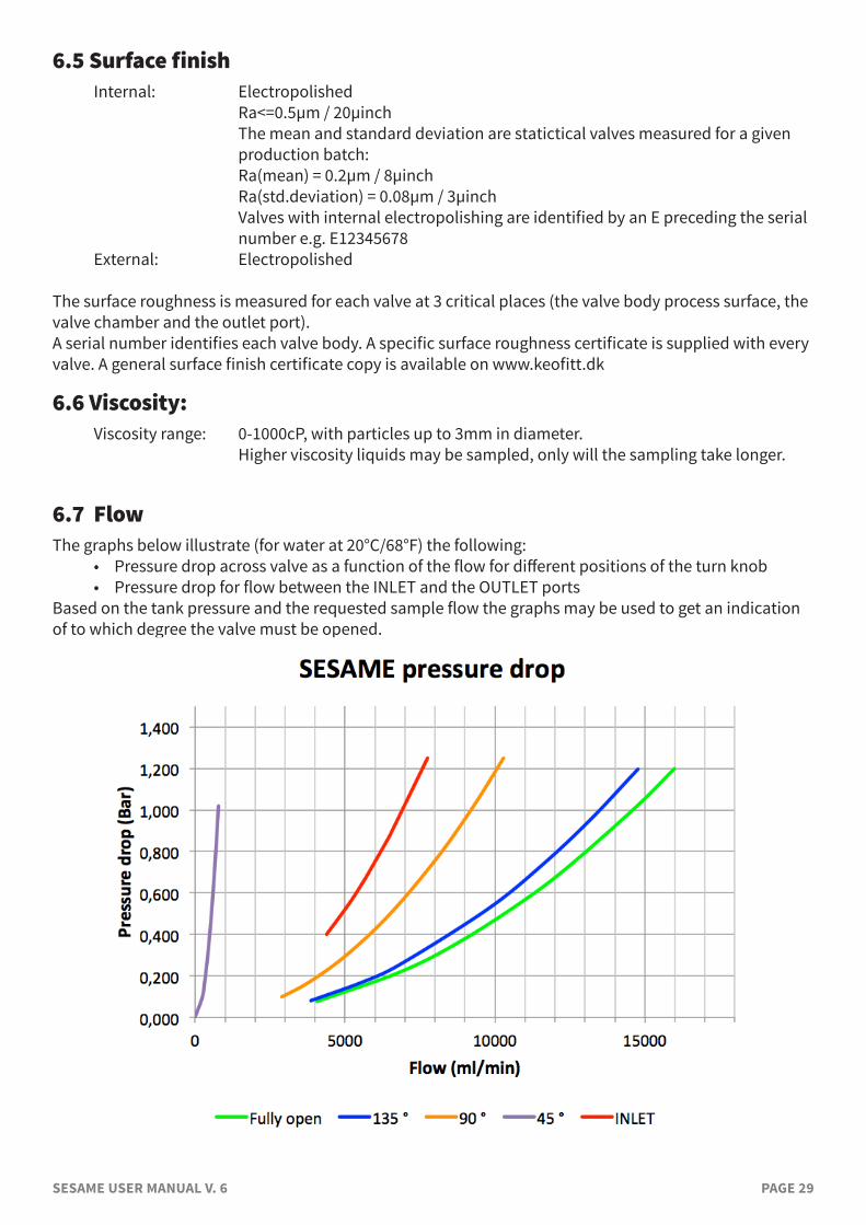
6.7 FlowThe graphs below illustrate (for water at 20°C/68°F) the following:
• Pressure drop across valve as a function of the flow for different positions of the turn knob• Pressure drop for flow between the INLET and the OUTLET ports
Based on the tank pressure and the requested sample flow the graphs may be used to get an indication of to which degree the valve must be opened.
SESAME USER MANUAL V. 6 PAGE 30
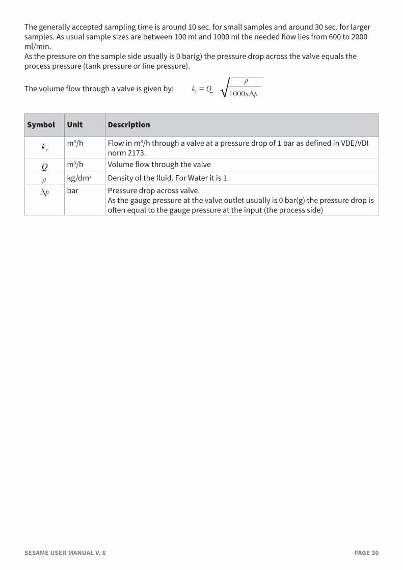
The generally accepted sampling time is around 10 sec. for small samples and around 30 sec. for larger samples. As usual sample sizes are between 100 ml and 1000 ml the needed flow lies from 600 to 2000 ml/min.As the pressure on the sample side usually is 0 bar(g) the pressure drop across the valve equals the process pressure (tank pressure or line pressure).
The volume flow through a valve is given by: kv = Q 1000x∆p————
ρ
Symbol Unit Description
�
kvm3/h Flow in m3/h through a valve at a pressure drop of 1 bar as defined in VDE/VDI
norm 2173.
�
Q m3/h Volume flow through the valve
ρ kg/dm3 Density of the fluid. For Water it is 1.
Δp bar Pressure drop across valve. As the gauge pressure at the valve outlet usually is 0 bar(g) the pressure drop is often equal to the gauge pressure at the input (the process side)
SESAME USER MANUAL V. 6 PAGE 31
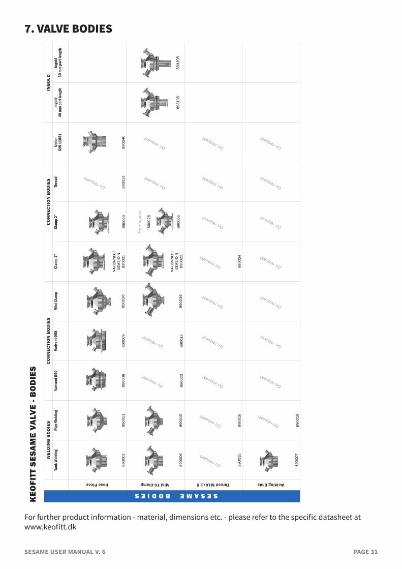
7. VALVE BODIESW
ELD
ING
BO
DIE
SC
ON
NEC
TIO
N B
OD
IES
C
ON
NEC
TIO
N B
OD
IES
ING
OLD
SESAME BODIES
Tank
Wel
ding
Pipe
Wel
ding
Variv
ent Ø
50Va
riven
t Ø68
Min
i Cla
mp
Clam
p 1”
Clam
p 2”
Thre
adUn
ion
DIN
1185
1In
gold
40 m
m p
ort l
engt
hIn
gold
50 m
m p
ort l
engt
h
Hose Piece
8900
0189
0011
8900
0889
0009
8900
36
NA-
CON
NEC
TAS
ME/
DIN
89
0021
8900
03
On request
8900
3189
0040
Mini Tri-Clamp
8900
0689
0010
On request
8900
20
On request
8900
1389
0039
N
A-CO
NN
ECT
ASM
E/D
IN89
0022
8900
26
8900
05
On request
On request
8931
0589
3205
Thread M16x1,5
On request
8900
15
On request
8900
16
On request
On request
On request
On request
8900
24
On request
On request
On request
Welding Ends
8900
07
On request
8900
19
On request
On request
On request
On request
On request
On request
On request
KEO
FITT
SES
AM
E VA
LVE
- BO
DIE
S
On
requ
est
For further product information - material, dimensions etc. - please refer to the specific datasheet at www.keofitt.dk
SESAME USER MANUAL V. 6 PAGE 32
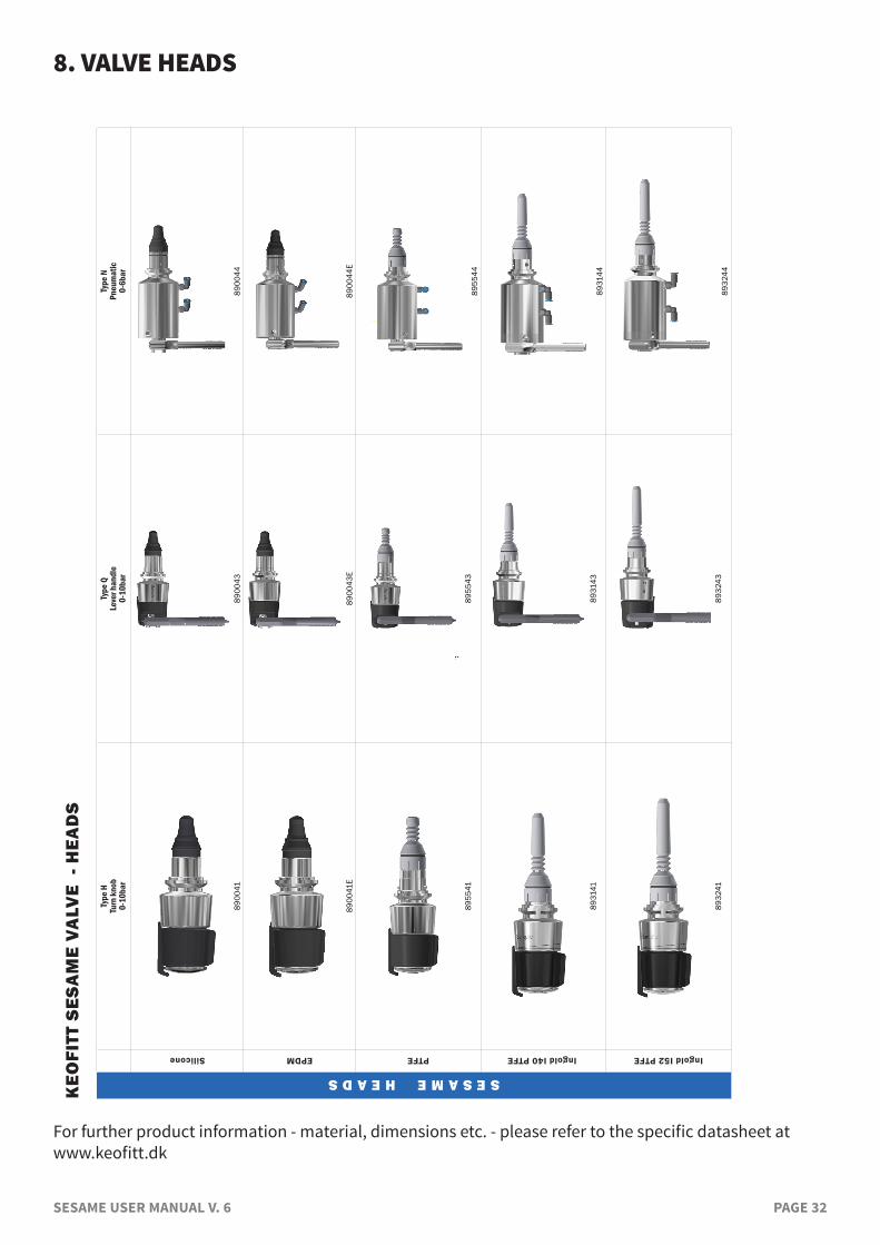
8. VALVE HEADS K
EOFI
TT S
ESA
ME
VALV
E -
HEA
DS
SESAME HEADS
Type
HTu
rn kn
ob0-
10ba
r
Type
Q
Le
ver h
andl
e0-
10ba
r
Type
N
Pneu
mat
ic
0-6b
ar
Silicone
8900
4189
0043
8900
44
EPDM
8900
41E
8900
43E
8900
44E
PTFE
8955
4189
5543
8955
44
Ingold I40 PTFE
8931
4189
3143
8931
44
Ingold I52 PTFE
8932
4189
3243
8932
44
For further product information - material, dimensions etc. - please refer to the specific datasheet at www.keofitt.dk
SESAME USER MANUAL V. 6 PAGE 33
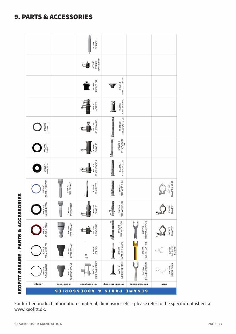
9. PARTS & ACCESSORIES K
EOFI
TT S
ESA
ME
- PA
RTS
& A
CC
ESSO
RIE
S
SESAME PARTS & ACCESSORIESO-Rings
4002
08O-
RIN
G 6
8 FD
A40
0308
EPD
M 4
2X3
FDA
8008
3010
.3X2
.4 E
PDM
8008
30E
10.3
X2.4
EPD
M88
0830
20,3
5X1,
78 E
PDM
9000
87G
ASKE
T ½
”90
0092
GAS
KET
2”Membranes
8900
51SI
LICO
NE
SESA
ME
8900
52EP
DM
SES
AME
8900
55PT
FE S
ESAM
E89
5531
PTFE
SES
AME
8955
32PT
FE S
ESAM
E
For hose piece
8000
58CO
IL W
980
0061
QC W
9 PL
UG80
0070
QC W
9 W
L80
0071
QC W
9 PT
FE80
0082
QC W
9 H
OSE
ID 7
8000
83QC
W9
TC80
0086
QC W
9 M
4 H
P55
0057
ADAP
TER
6000
62RU
BBER
CAP
For mini tri-clamp For valve heads
6001
70Q
HAN
DLE
/TYP
E N
8802
55TO
OL R
EFLE
X PT
FE89
0170
Q H
AND
LE/T
YPE
Q
Misc.
8900
64D
OUBL
E ST
. S
T. C
HAI
N
5500
02.2
PTFE
W/Q
C/TC
O.
5M
5500
03.2
PTFE
W/Q
C/TC
1M
9000
91G
ASKE
T 1”
9000
86CL
AMP
1”90
0189
CLAM
P D
N 1
0-20
9000
75CL
AMP
½”
8000
14M
INIC
/ 1
” CL
AMP
9000
96AD
APTE
R W
9/TC
9000
13M
INIC
LAM
P SP
IKE
5500
05PT
FE W
/TC
1.0M
5500
04PT
FE W
/TC
0.5M
5500
03PT
FE W
/QC
1.0M
5500
02PT
FE W
/QC
O.5M
3000
21CL
AMP/
PTFE
10/
8
9000
45SY
RIN
GE
ADAP
TER
W9
9000
82SY
RIN
GE
8900
63SI
NG
LE C
HAI
N
8000
13SP
IKE
BAG
HOL
DER
For further product information - material, dimensions etc. - please refer to the specific datasheet at www.keofitt.dk.
SESAME USER MANUAL V. 6 PAGE 34
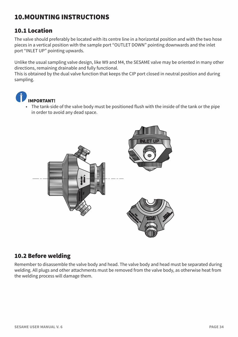
10.MOUNTING INSTRUCTIONS
10.1 LocationThe valve should preferably be located with its centre line in a horizontal position and with the two hose pieces in a vertical position with the sample port “OUTLET DOWN” pointing downwards and the inlet port “INLET UP” pointing upwards.
Unlike the usual sampling valve design, like W9 and M4, the SESAME valve may be oriented in many other directions, remaining drainable and fully functional. This is obtained by the dual valve function that keeps the CIP port closed in neutral position and during sampling.
IMPORTANT!• The tank-side of the valve body must be positioned flush with the inside of the tank or the pipe
in order to avoid any dead space.
1
1
2
2
3
3
4
4
5
5
6
6
A A
B B
C C
D D
14-09-2016
Confidential: Property of Keofitt A/S. Not to be handed over to, copied or used by third party. 2D/3D reproduction of contents to be authorized by Keofitt A/S
Title Date
Drawing No. 890001 med grafik
10.2 Before weldingRemember to disassemble the valve body and head. The valve body and head must be separated during welding. All plugs and other attachments must be removed from the valve body, as otherwise heat from the welding process will damage them.
SESAME USER MANUAL V. 6 PAGE 35
11. WELDING INSTRUCTIONS
Valves for welding are available in two types: T (tank) and P (pipe).1. For type T (tank) it is necessary to drill a hole ø38 mm into the tank wall, and then fit the valve
into this hole flush with the inside of the tank. Welding should be carried out as a penetration welding. Material thickness less than 4 mm: Weld from inside. Material thickness greater than 4 mm: Weld from both outside and inside. Since type T has a solid end piece, the valve will not be damaged by penetration welding. However, the use of purge gas in the form of either Argon or Formier gas is recommended in order to give the best result.
2. For type P (pipe) penetration welding must be carried out from outside. The valve is machined with a recess-like shoulder on the outside of the end piece which gives approximately the same material thickness (1.5mm material thickness) as in the pipe wall. This machined shoulder can be modified according to the customer’s wishes.
IMPORTANT!• When grinding/polishing the internal weld, the valve seat must not be touched.
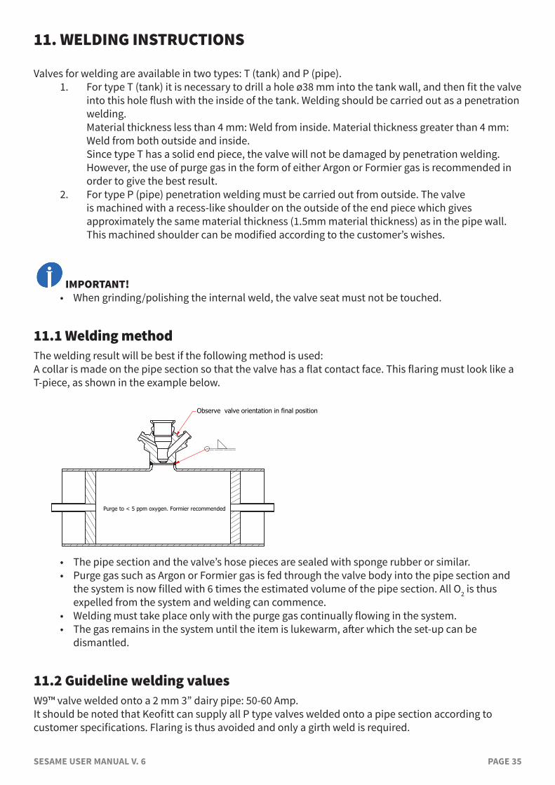
11.1 Welding methodThe welding result will be best if the following method is used:A collar is made on the pipe section so that the valve has a flat contact face. This flaring must look like a T-piece, as shown in the example below.
A-A ( 1 : 2 )
A
A
1
1
2
2
3
3
4
4
5
5
6
6
A A
B B
C C
D D
14-09-2016
Confidential: Property of Keofitt A/S. Not to be handed over to, copied or used by third party. 2D/3D reproduction of contents to be authorized by Keofitt A/S
Title Date
Drawing No. 890021 isvejst i rør
Observe valve orientation in final position
Purge to < 5 ppm oxygen. Formier recommended
• The pipe section and the valve’s hose pieces are sealed with sponge rubber or similar.• Purge gas such as Argon or Formier gas is fed through the valve body into the pipe section and
the system is now filled with 6 times the estimated volume of the pipe section. All O2 is thus expelled from the system and welding can commence.
• Welding must take place only with the purge gas continually flowing in the system.• The gas remains in the system until the item is lukewarm, after which the set-up can be
dismantled.
11.2 Guideline welding valuesW9™ valve welded onto a 2 mm 3” dairy pipe: 50-60 Amp.It should be noted that Keofitt can supply all P type valves welded onto a pipe section according to customer specifications. Flaring is thus avoided and only a girth weld is required.
SESAME USER MANUAL V. 6 PAGE 36
12. BLOCK DIAGRAMS
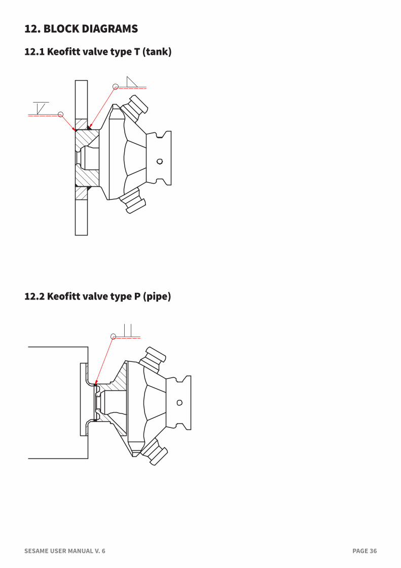
12.1 Keofitt valve type T (tank)
1
1
2
2
3
3
4
4
5
5
6
6
A A
B B
C C
D D
26-09-2016
Confidential: Property of Keofitt A/S. Not to be handed over to, copied or used by third party. 2D/3D reproduction of contents to be authorized by Keofitt A/S
Title Date
Drawing No. 890301 i svejst tank
12.2 Keofitt valve type P (pipe)
1
1
2
2
3
3
4
4
5
5
6
6
A A
B B
C C
D D
26-09-2016
Confidential: Property of Keofitt A/S. Not to be handed over to, copied or used by third party. 2D/3D reproduction of contents to be authorized by Keofitt A/S
Title Date
Drawing No. 890511 svejst i rør
SESAME USER MANUAL V. 6 PAGE 37
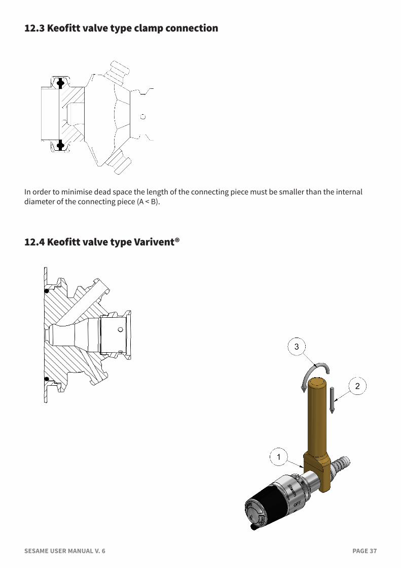
12.3 Keofitt valve type clamp connection
In order to minimise dead space the length of the connecting piece must be smaller than the internal diameter of the connecting piece (A < B).
12.4 Keofitt valve type Varivent®
SESAME USER MANUAL V. 6 PAGE 38
13. MAINTENANCE
13.1 Maintenance
All membranes must be inspected between batches. The EPDM and Silicon membranes should be replaced at every batch change or at least every 2-3 months. PTFE membranes should be replaced every 12 months. In the event of intensive sterilisation and cleaning it may be necessary to replace it more frequently. The appropriate replacement frequency should be determined by the user by starting with short intervals and continuously extend the time in use until one reaches the limit of the membrane’s durability. Based on the desired safety margin the user then decides on the replacement interval to adapt.In each individual case a standard operating procedure including maintance intervals should be endorsed based on experience. For disassembly of valve body and valve head, see instructions in chapter 13.3.
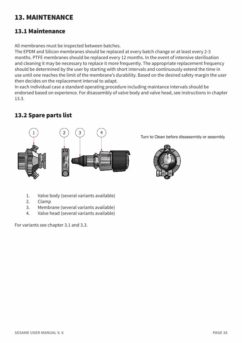
13.2 Spare parts list
1. Valve body (several variants available)2. Clamp3. Membrane (several variants available)4. Valve head (several variants available)
For variants see chapter 3.1 and 3.3.
SESAME USER MANUAL V. 6 PAGE 39
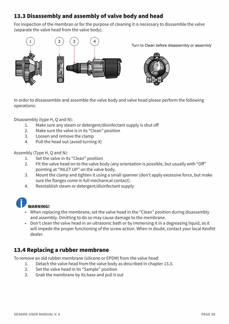
13.3 Disassembly and assembly of valve body and headFor inspection of the membran or for the purpose of cleaning it is necessary to disssemble the valve (separate the valve head from the valve body).
In order to dissassemble and assemble the valve body and valve head please perform the following operations:
Disassembly (type H, Q and N):1. Make sure any steam or detergent/disinfectant supply is shut off2. Make sure the valve is in its “Clean” position3. Loosen and remove the clamp4. Pull the head out (avoid turning it)
Assembly (Type H, Q and N):1. Set the valve in its “Clean” position2. Fit the valve head on to the valve body (any orientation is possible, but usually with “Off”
pointing at “INLET UP” on the valve body.3. Mount the clamp and tighten it using a small spanner (don’t apply excessive force, but make
sure the flanges come in full mechanical contact).4. Reestablish steam or detergent/disinfectant supply
WARNING!• When replacing the membrane, set the valve head in the “Clean” position during disassembly
and assembly. Omitting to do so may cause damage to the membrane.• Don’t clean the valve head in an ultrasonic bath or by immersing it in a degreasing liquid, as it
will impede the proper functioning of the screw action. When in doubt, contact your local Keofitt dealer.
13.4 Replacing a rubber membrane To remove an old rubber membrane (silicone or EPDM) from the valve head:
1. Detach the valve head from the valve body as described in chapter 13.3.2. Set the valve head in its “Sample” position 3. Grab the membrane by its base and pull it out
SESAME USER MANUAL V. 6 PAGE 40
To attach a new membrane to the valve head:4. Set the valve head to “Sample” position.5. Place the new membrane on valve head and press the new membrane against the steel shoulder in order to allow the membrane to lock into the groove.6. Set the valve head in its “Clean” position.7. If necessary push the tip of the membrane sideways until it sits perfectly co-axial with the
valve head.8. Insert the valve head into the valve body and mount the clamp as described in chapter 13.2.9. Set the valve in its “OFF” position.
13.5 Instructions on replacing a PTFE membrane
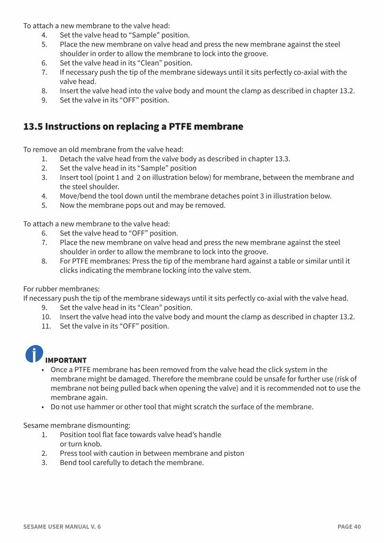
To remove an old membrane from the valve head: 1. Detach the valve head from the valve body as described in chapter 13.3. 2. Set the valve head in its “Sample” position3. Insert tool (point 1 and 2 on illustration below) for membrane, between the membrane and
the steel shoulder.4. Move/bend the tool down until the membrane detaches point 3 in illustration below.5. Now the membrane pops out and may be removed.
To attach a new membrane to the valve head: 6. Set the valve head to “OFF” position.7. Place the new membrane on valve head and press the new membrane against the steel
shoulder in order to allow the membrane to lock into the groove. 8. For PTFE membranes: Press the tip of the membrane hard against a table or similar until it
clicks indicating the membrane locking into the valve stem.
For rubber membranes:If necessary push the tip of the membrane sideways until it sits perfectly co-axial with the valve head.
9. Set the valve head in its “Clean” position. 10. Insert the valve head into the valve body and mount the clamp as described in chapter 13.2.11. Set the valve in its “OFF” position.
IMPORTANT• Once a PTFE membrane has been removed from the valve head the click system in the
membrane might be damaged. Therefore the membrane could be unsafe for further use (risk of membrane not being pulled back when opening the valve) and it is recommended not to use the membrane again.
• Do not use hammer or other tool that might scratch the surface of the membrane.
Sesame membrane dismounting: 1. Position tool flat face towards valve head’s handle or turn knob.2. Press tool with caution in between membrane and piston3. Bend tool carefully to detach the membrane.
SESAME USER MANUAL V. 6 PAGE 41
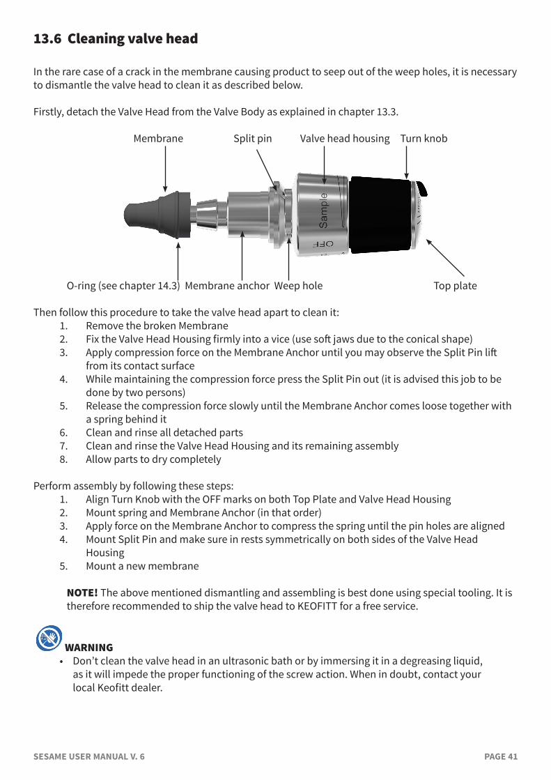
13.6 Cleaning valve head
In the rare case of a crack in the membrane causing product to seep out of the weep holes, it is necessary to dismantle the valve head to clean it as described below.
Firstly, detach the Valve Head from the Valve Body as explained in chapter 13.3.
Membrane Split pin Valve head housing Turn knob
O-ring (see chapter 14.3) Membrane anchor Weep hole Top plate
Then follow this procedure to take the valve head apart to clean it:1. Remove the broken Membrane2. Fix the Valve Head Housing firmly into a vice (use soft jaws due to the conical shape)3. Apply compression force on the Membrane Anchor until you may observe the Split Pin lift
from its contact surface4. While maintaining the compression force press the Split Pin out (it is advised this job to be
done by two persons)5. Release the compression force slowly until the Membrane Anchor comes loose together with
a spring behind it6. Clean and rinse all detached parts7. Clean and rinse the Valve Head Housing and its remaining assembly8. Allow parts to dry completely
Perform assembly by following these steps:1. Align Turn Knob with the OFF marks on both Top Plate and Valve Head Housing2. Mount spring and Membrane Anchor (in that order)3. Apply force on the Membrane Anchor to compress the spring until the pin holes are aligned4. Mount Split Pin and make sure in rests symmetrically on both sides of the Valve Head
Housing5. Mount a new membrane
NOTE! The above mentioned dismantling and assembling is best done using special tooling. It is therefore recommended to ship the valve head to KEOFITT for a free service.
WARNING• Don’t clean the valve head in an ultrasonic bath or by immersing it in a degreasing liquid,
as it will impede the proper functioning of the screw action. When in doubt, contact your local Keofitt dealer.
SESAME USER MANUAL V. 6 PAGE 42
14. FAILURE MODES
If the membrane is not replaced with a new one at regular intervals (depending on the application), it may eventually break, usually around the tip and more seldomly along the side or at the integrated o-ring.
14.1 Broken membrane tipThis failure usually causes product to leak from the process side and more or less product will flow out through the lower port, also when the valve is in closed position. As such the valve port acts as a leakage hole (weep hole).
14.2 Broken membrane sideA longitudinal slit in the membrane is a rare incident and will only occur if the membrane has been kept in operation far beyond its expected service life.Should it happen, product will during sampling enter the cavity between the internal surface of the membrane and the rod operating the membrane. As there is no significant pressure in the valve chamber during sampling product will only flow slowly through the slit andwill eventually flow through the weep hole shown in the illustration in chapter 13.6. However, this is likely to take many rounds of samplings due to the short sampling time and the very low pressure on the external side of the membrane.
14.3 Broken integrated o-ringThe even more rare incident of a broken integrated o-ring will cause leakage along the inside wall of the part of the valve body, on to which the valve head is clamped.The integrated o-ring seals between the steam/CIP compartment of the valve and the exterior. In case of a malfunction steam or CIP liquid will flow through a weep hole in the valve body, just below the clamp section.
14.4 Cleaning the valve after a failureIn case of any of the above failures the valve needs to be completely taken apart a cleaned properly using a non-abrasive cleaning agent by performing the following sequence of operations (the choice of cleaning agent is for the user to decide as it depends on the product in the process line):
1. Detach the valve head from the valve body as explained in chapter 13.32. Disassemble the valve head as explained in chapter 13.63. Clean all individual components from the disassembled valve head4. Clean the valve body5. Assemble the valve head as explained in chapter 13.6 and fit a new membrane (see chapter
13.4 or 13.5)6. Fit the valve head to the valve body as explained in chapter 13.3
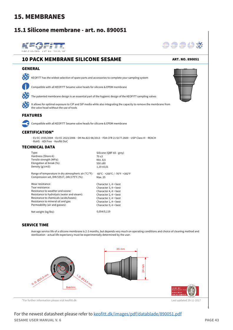
SESAME USER MANUAL V. 6 PAGE 43
15. MEMBRANES
15.1 Silicone membrane - art. no. 890051
For the newest datasheet please refer to keofitt.dk/images/pdf/datablade/890051.pdf
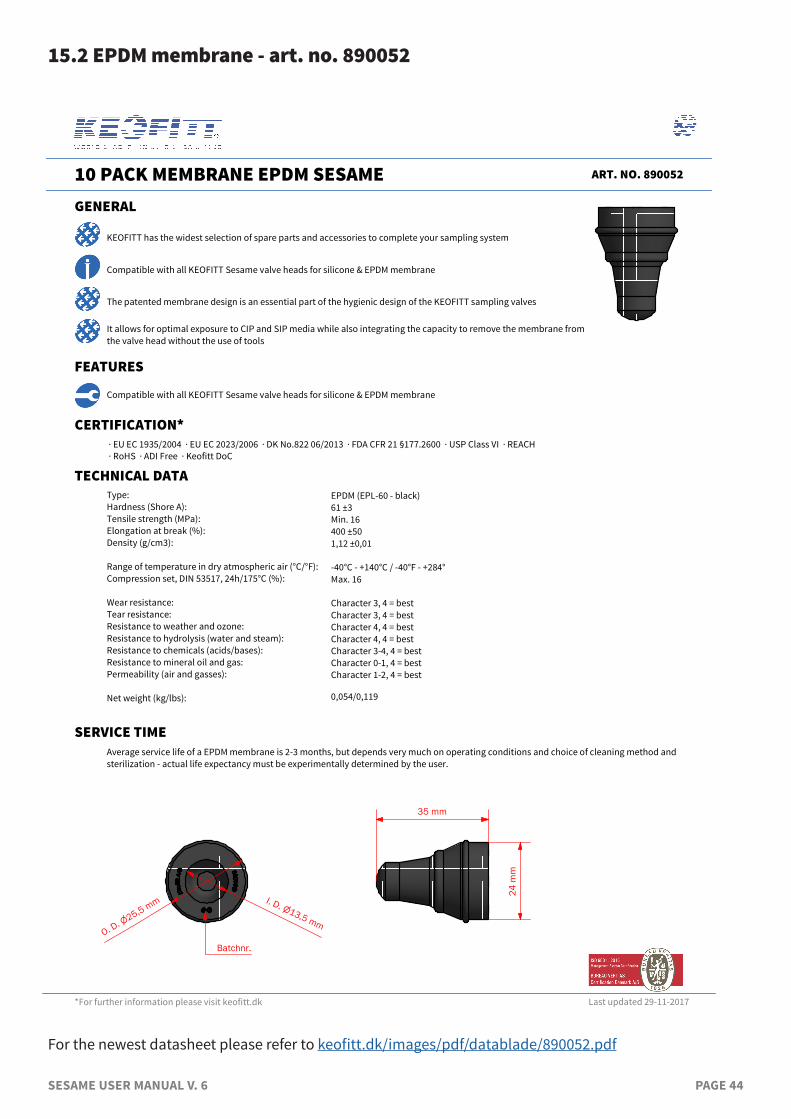
SESAME USER MANUAL V. 6 PAGE 44
15.2 EPDM membrane - art. no. 890052
For the newest datasheet please refer to keofitt.dk/images/pdf/datablade/890052.pdf
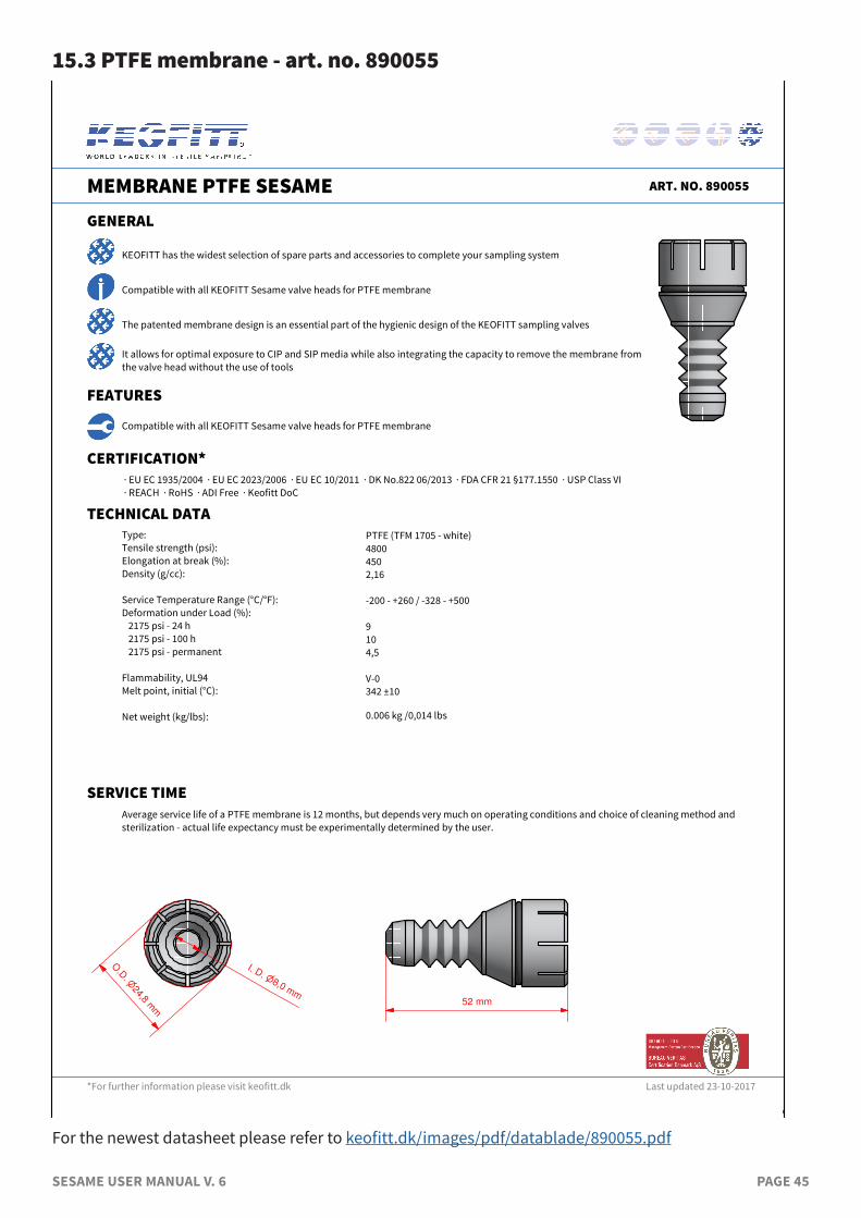
SESAME USER MANUAL V. 6 PAGE 45
15.3 PTFE membrane - art. no. 890055
52 mm
24,8
O.D
.
mm
8,0
I. D.
mm
For the newest datasheet please refer to keofitt.dk/images/pdf/datablade/890055.pdf
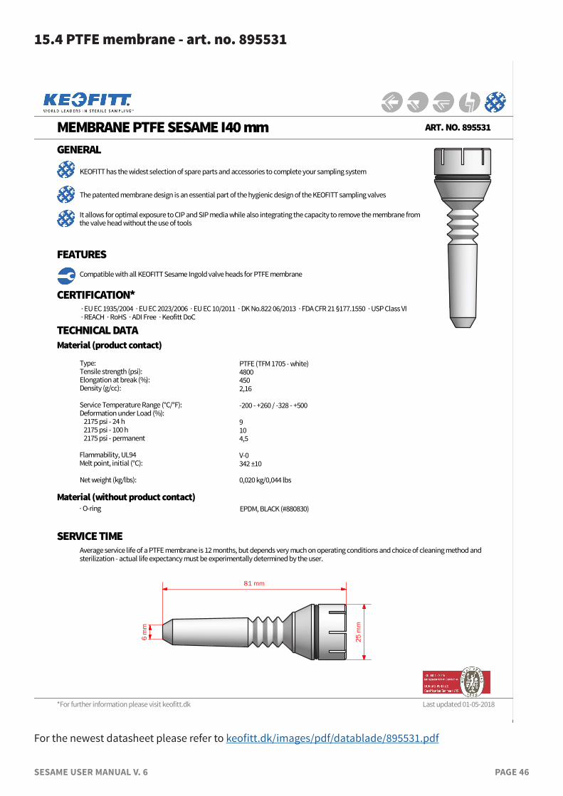
SESAME USER MANUAL V. 6 PAGE 46
15.4 PTFE membrane - art. no. 895531
*For further information please visit keofitt.dk
MEMBRANE PTFE SESAME I40 mm ART. NO. 895531
GENERAL
KEOFITT has the widest selection of spare parts and accessories to complete your sampling system
Compatible with all KEOFITT Sesame Ingold valve heads for PTFE membrane
CERTIFICATION* · EU EC 1935/2004 · EU EC 2023/2006 · EU EC 10/2011 · DK No.822 06/2013 · FDA CFR 21 §177.1550 · USP Class VI · REACH · RoHS · ADI Free · Keofitt DoC
TECHNICAL DATA
Type: Tensile strength (psi):Elongation at break (%):Density (g/cc): Service Temperature Range (°C/°F):Deformation under Load (%): 2175 psi - 24 h 2175 psi - 100 h 2175 psi - permanent Flammability, UL94Melt point, initial (°C): Net weight (kg/lbs):
PTFE (TFM 1705 - white)48004502,16 -200 - +260 / -328 - +500 910 4,5 V-0342 ±10
0,020 kg/0,044 lbs
It allows for optimal exposure to CIP and SIP media while also integrating the capacity to remove the membrane from the valve head without the use of tools
FEATURES
SERVICE TIMEAverage service life of a PTFE membrane is 12 months, but depends very much on operating conditions and choice of cleaning method and sterilization - actual life expectancy must be experimentally determined by the user.
Last updated 01-05-2018
Material (without product contact)
Material (product contact)
· O-ring EPDM, BLACK (#880830)
The patented membrane design is an essential part of the hygienic design of the KEOFITT sampling valves
25 m
m
81 mm
6 m
m
For the newest datasheet please refer to keofitt.dk/images/pdf/datablade/895531.pdf
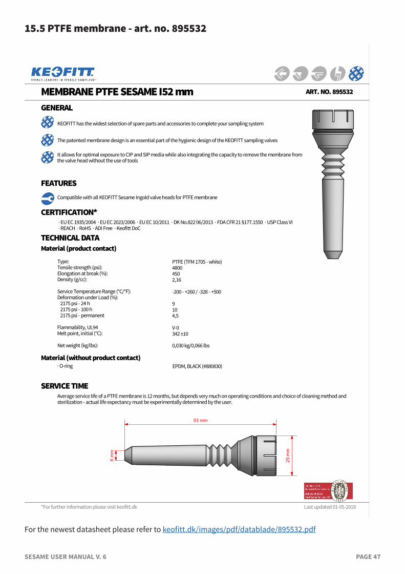
SESAME USER MANUAL V. 6 PAGE 47
15.5 PTFE membrane - art. no. 895532
*For further information please visit keofitt.dk
MEMBRANE PTFE SESAME I52 mm ART. NO. 895532
GENERAL
KEOFITT has the widest selection of spare parts and accessories to complete your sampling system
Compatible with all KEOFITT Sesame Ingold valve heads for PTFE membrane
CERTIFICATION* · EU EC 1935/2004 · EU EC 2023/2006 · EU EC 10/2011 · DK No.822 06/2013 · FDA CFR 21 §177.1550 · USP Class VI · REACH · RoHS · ADI Free · Keofitt DoC
TECHNICAL DATA
Type: Tensile strength (psi):Elongation at break (%):Density (g/cc): Service Temperature Range (°C/°F):Deformation under Load (%): 2175 psi - 24 h 2175 psi - 100 h 2175 psi - permanent Flammability, UL94Melt point, initial (°C): Net weight (kg/lbs):
PTFE (TFM 1705 - white)48004502,16 -200 - +260 / -328 - +500 910 4,5 V-0342 ±10
0,030 kg/0,066 lbs
It allows for optimal exposure to CIP and SIP media while also integrating the capacity to remove the membrane from the valve head without the use of tools
FEATURES
SERVICE TIMEAverage service life of a PTFE membrane is 12 months, but depends very much on operating conditions and choice of cleaning method and sterilization - actual life expectancy must be experimentally determined by the user.
Last updated 01-05-2018
Material (without product contact)
Material (product contact)
· O-ring EPDM, BLACK (#880830)
The patented membrane design is an essential part of the hygienic design of the KEOFITT sampling valves
93 mm
6 m
m
25 m
m
For the newest datasheet please refer to keofitt.dk/images/pdf/datablade/895532.pdf

DON’T GAMBLE WITH YOUR SAMPLE™
KEOFITT A/SKullinggade 31DK-5700 SvendborgDenmark
Phone +45 6316 7080Fax +45 6316 7081
Keofitt reserves the right to change technical data without notice!For complete set of updated data sheets and manuals for Keofitt products please refer to our web page www.keofitt.dk