
Simple Loop Antennas y TWR onaire Engineering Pedersens Loop Antenna... · The Tuned Loop Antenna...
13
Improving Medium Wave Reception Simple Loop Antennas By TWR Bonaire Engineering Dave Pedersen [email protected] The Problem with listening to distant medium wave radio stations Radio stations on the “Medium Wave” (MW), or AM band, are can be difficult to hear clearly. Weak incoming radio signals, low power transmitters, as well as noise from thunderstorms, electrical wiring and all kinds of electronic devices all combine to make reception difficult at times. In most cases a major cause for poor reception lies within the receiving radio itself. The antenna inside the average portable radio is very poor. In this article, we will discuss a very low, or even zero, cost antenna that can be easily built that will dramatically improve medium wave (MW) reception. The antenna we will talk about is only for MW, not for shortwave or FM. The antenna we are talking about is the “Tuned Loop Antenna”. This article will describe the problem, and how to build your own loop antenna at very low cost with very little technical skills. In this article, we will also use some “technical talk” that hopefully will help you understand the problem and the solution a bit better. Understanding Signal to Noise ratio In order to have good, listenable reception where we can understand the programs, we need to maximize the desired radio station signal while reducing the noise and interference which make listening difficult. If you think about it then, our goal is not to get the strongest signal, but rather to get the strongest signal AND reduce the “noise” which is any signal we don’t want. Noise can come from electrical wiring, appliances and computers, thunderstorms, and even other radio stations on the adjacent frequency or even right on the same frequency that we want to listen to. In engineering terms, what we want is the best possible “Signal to Noise Ratio” (S/N ratio, or SNR). So, signal we want, noise we don’t want.
Transcript of Simple Loop Antennas y TWR onaire Engineering Pedersens Loop Antenna... · The Tuned Loop Antenna...

Improving Medium Wave Reception
Simple Loop Antennas
By TWR Bonaire Engineering
Dave Pedersen
The Problem with listening to distant medium wave radio stations
Radio stations on the “Medium Wave” (MW), or AM band, are can be difficult to hear clearly. Weak
incoming radio signals, low power transmitters, as well as noise from thunderstorms, electrical wiring
and all kinds of electronic devices all combine to make reception difficult at times.
In most cases a major cause for poor reception lies within the receiving radio itself. The antenna inside
the average portable radio is very poor. In this article, we will discuss a very low, or even zero, cost
antenna that can be easily built that will dramatically improve medium wave (MW) reception. The
antenna we will talk about is only for MW, not for shortwave or FM. The antenna we are talking about is
the “Tuned Loop Antenna”. This article will describe the problem, and how to build your own loop
antenna at very low cost with very little technical skills.
In this article, we will also use some “technical talk” that hopefully will help you understand the problem
and the solution a bit better.
Understanding Signal to Noise ratio
In order to have good, listenable reception where we can understand the programs, we need to
maximize the desired radio station signal while reducing the noise and interference which make
listening difficult. If you think about it then, our goal is not to get the strongest signal, but rather to get
the strongest signal AND reduce the “noise” which is any signal we don’t want. Noise can come from
electrical wiring, appliances and computers, thunderstorms, and even other radio stations on the
adjacent frequency or even right on the same frequency that we want to listen to. In engineering terms,
what we want is the best possible “Signal to Noise Ratio” (S/N ratio, or SNR). So, signal we want, noise
we don’t want.

So how do we improve Signal / Noise ratio?
Well, the transmitter could increase power, but that is expensive and not likely to happen. If changes are
not possible at the transmitter, all the improvements will have to be at the receiver end. Now part of the
problem with small portable radios is that the built-in antennas are usually very, very poor. They are
physically small, and we say that they have a “small capture area”. There is just not much antenna there
to grab, or capture, the signal out of the air. This small capture area does not pick up the signal well, so
reception is weak. Another problems is that the small antennas are not very directional. This
“directivity” is a useful tool that can help reduce unwanted interference.
The little antennas inside the radios are called “loopsticks” because they are made from loops of fine
wire wrapped around a rod of ferrite material. The pictures below show two typical small loop stick
antennas. These loopsticks are typically 3-9 cm long.
How they work is that any loop of wire has a magnetic field. When that magnetic field picks up the
magnetic field energy lines from the transmitter signal, some of that energy is converted into electricity
and fed into the radio amplifier circuits.
Improving the radio antenna
What we need is an antenna with a much bigger “capture area”, something that can pull more of the
transmitter signal out of the air. We could consider outdoor antennas but they are more visible, attract
attention, are expensive to build, and most radios don’t have a way to connect them to the radio
anyway. At the low frequencies used for medium wave broadcasting, good outdoor antennas are quite
big. They should also be cut to a certain size to work efficiently for each given station’s frequency, and
are very hard to adjust. What we need is a good, small, cheap indoor antenna.
The “loop” in the typical radio’s loopstick actually does a surprisingly good job for its size. We just need a
bigger loop. That would give us more capture area and can be used indoors with very god results. For a
loop antenna to be really efficient, it needs to be adjusted, or “tuned” to the specific frequency of the
station you want to listen to. The specific antenna we will focus on is a “Tuned Loop Antenna”
The Tuned Loop Antenna
Loop antennas have been used for more than 100 years. Tuned loop antennas were first popularized in
the 1940s. There are numerous designs and variations, as well as commercial products, but they all
follow the same basic design. The tuned loop antenna is easy to build at home.
The tuned loop antenna provides a dramatic improvement in reception quality, often 10-100 times
better than a loopstick. Weak or barely detectable stations can become easy to listen to.
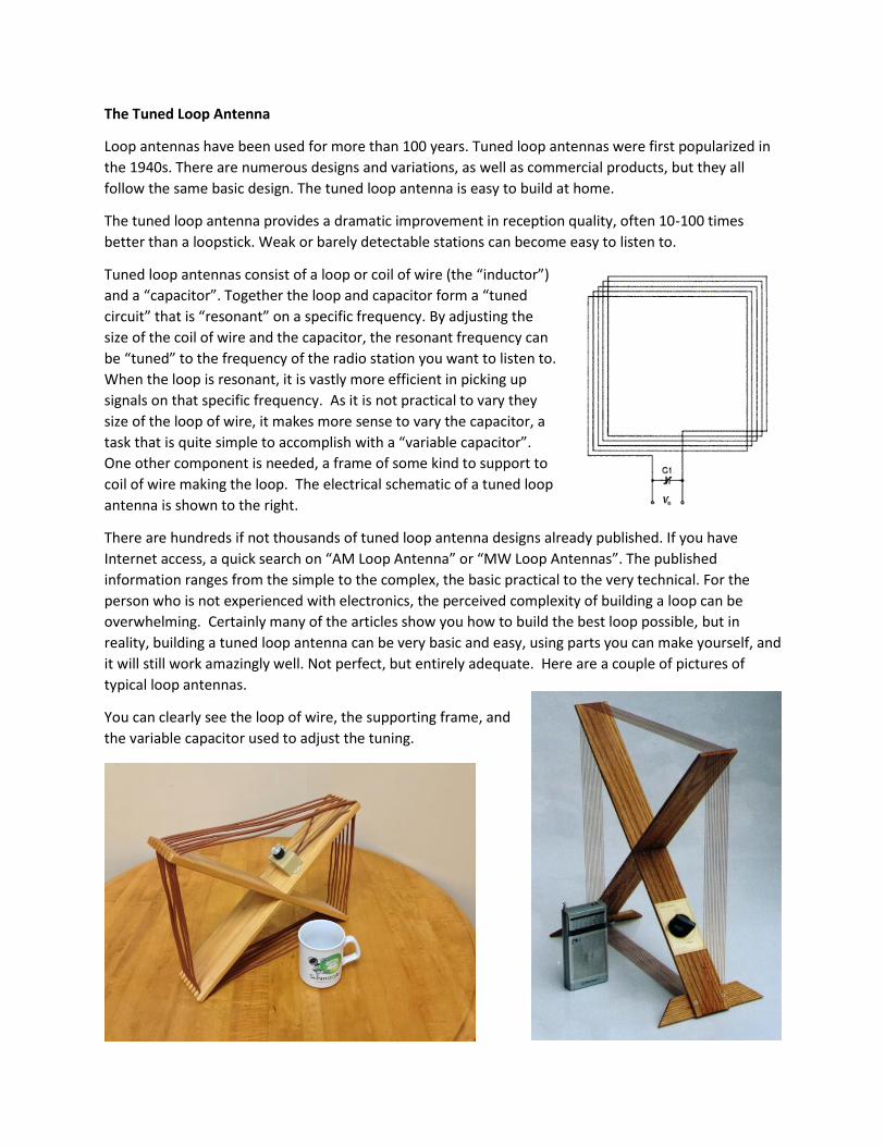
Tuned loop antennas consist of a loop or coil of wire (the “inductor”)
and a “capacitor”. Together the loop and capacitor form a “tuned
circuit” that is “resonant” on a specific frequency. By adjusting the
size of the coil of wire and the capacitor, the resonant frequency can
be “tuned” to the frequency of the radio station you want to listen to.
When the loop is resonant, it is vastly more efficient in picking up
signals on that specific frequency. As it is not practical to vary they
size of the loop of wire, it makes more sense to vary the capacitor, a
task that is quite simple to accomplish with a “variable capacitor”.
One other component is needed, a frame of some kind to support to
coil of wire making the loop. The electrical schematic of a tuned loop
antenna is shown to the right.
There are hundreds if not thousands of tuned loop antenna designs already published. If you have
Internet access, a quick search on “AM Loop Antenna” or “MW Loop Antennas”. The published
information ranges from the simple to the complex, the basic practical to the very technical. For the
person who is not experienced with electronics, the perceived complexity of building a loop can be
overwhelming. Certainly many of the articles show you how to build the best loop possible, but in
reality, building a tuned loop antenna can be very basic and easy, using parts you can make yourself, and
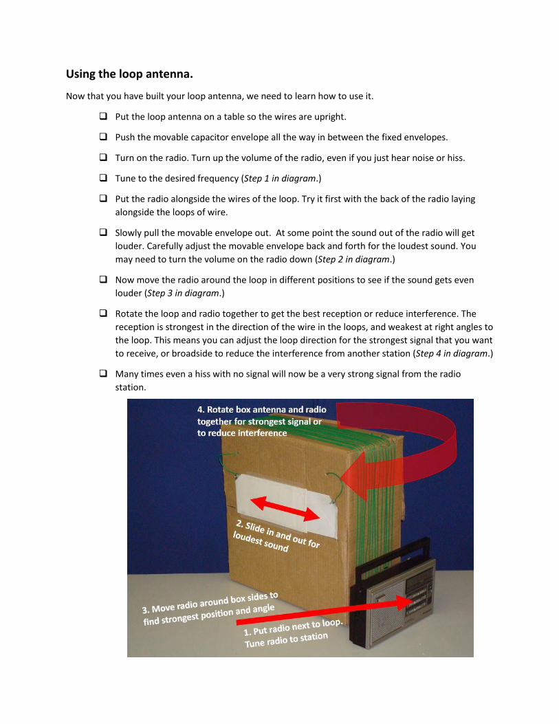
it will still work amazingly well. Not perfect, but entirely adequate. Here are a couple of pictures of
typical loop antennas.
You can clearly see the loop of wire, the supporting frame, and
the variable capacitor used to adjust the tuning.

The Problem with most loop antenna designs
Traditional tuned loop antenna designs have a number of problems for the unskilled builder who just
wants better reception. These include:
Complicated frames
Variable capacitors are hard to find, or expensive
Some loops are hard to build
Lots of complicated and very detailed plans to follow exactly.
We need a simpler design. Here are the design goals for a “Simple Loop” antenna.
The Simple Loop
A simpler design loop antenna for MW reception should meet the following goals:
Work almost as well as big loops
Very cheap to build (free is better!)
Only 30 minutes to build
No hard to find or expensive parts
No special tools
Very forgiving design with no specific dimensions
No connections inside the radio
These goals are very easy to meet.
The Simple Loop really only has three main parts:
A loop of wire
A frame to support the wire loop
A variable capacitor to tune the loop.
We will now take a closer look at each part.
The Wire Loop
The Simple Loop requires about 20-25m of wire. A little more is okay, but not less. It needs to be
insulated with plastic or even varnished enamel like transformer wire. The wire should be 0.5-1mm
diameter (26AWG-18AWG). Bigger wire is hard to bend but works okay, and smaller wire can break
more easily. Stranded wire is also better than solid wire as it is more flexible. This makes connections to
the variable capacitor more reliable. None of these details are very exact. Basically use what you can
find.

The Frame
The frame supports the wire in the loop shape. The “loop” can be square, rectangular, diamond shaped
or even round. The exact shape is not critical. The most common designs published use a wooden X-
shaped frame as shown earlier in some of the pictures. The frame should be made of insulating material.
Wood or plastic works fine, metal will not. The exact shape or size is not critical.
The traditional materials and designs can be difficult to build mechanically. What we want is something
very simple and inexpensive. The Simple Loop uses a cardboard box. Suitable sizes are 40x40 cm to
100x100 cm. The box should be at least 10-20 cm wide as the turns of the wire loop are 1 cm apart. A
bigger box will need fewer turns to use up the 25m of wire, so can be thinner. The box can also be
rectangular rather than round, such as 30 x 50cm. If you only have small boxes, tape them together to
make a bigger box. Basically, just use what you can find.
Bigger loops will be more sensitive than smaller loops, and pick up weaker signals. The bigger loops will
also do a better job of reducing interference from other stations.
The Variable Tuning Capacitor
The variable capacitor is usually the most difficult to find or expensive part of the loop antenna. Some
loop builders recycle old ones from old MW radios. A variable capacitor is really just two or more metal
plates or surfaces sliding past each other, very close but not touching.
Fortunately, a variable capacitor is actually very easy and cheap to build. Our variable capacitor is going
to be built with envelopes, stiff paper or cards, and aluminum foil. The foil wraps around a piece of card
stock. The card is placed inside an envelope. We will make three plates and put them together like a
sandwich, with one sliding in and out inside the other two fixed envelopes.
Background Summary
So, that is the background on the Simple Loop. Expert builders might find the fancier designs work a bit
better, but our goal is to build an antenna that works quite well at low or even zero cost, our of parts
and pieces you can find in a remote location. In addition, it can be built by listeners with no specials
tools and skills in radio engineering.
Let’s now actually build our Simple Loop antenna.

Building the Simple Loop
What will we need?
The Simple Loop is made of just a few items that you can hopefully find for free or very low cost. Here is
a list of the materials we need.
A cardboard box, 40x40 - 100x100cm, by 20cm thick
25m of small insulated wire
3 business size envelopes
3 pieces of stiff card stock
2 small nuts and bolts
Some adhesive tape
Wire cutter
Knife or hacksaw
Pair of scissors
Screwdriver
Pen
The Assembly Steps
Now that we have gathered our parts, let’s actually build the Simple Loop Antenna. We will divide the
tasks into four steps.
1. Preparing the frame
2. Winding the wire loop onto the frame
3. Building the capacitors
4. Putting it all together

Preparing the frame
The first step is to prepare the cardboard box to act as the frame
for the loop.
Get a cardboard box, about 40x40cm – 100x100cm by 10-
20cm thick. A square box is best but a rectangle shape is okay
as long as long as two sides are reasonably close to the same
length.
Mark the four short 10-20cm edges with lines every 5-
10mm apart so you have about 15 lines.
Cut small slits on each line on all four short edges with
a knife to hold wires in place. A hacksaw works well as
it makes a wider slit. The slits only need to be 5-10 mm
deep.
Make three small holes 1cm apart near one corner by
the first slit. You can see the small holes with the wire
through them in the next picture below.
Winding the loop
Once the cardboard box frame has been marked and the edge slits cut, the wire loop can be wound onto
the frame.
Use 20-25m of wire for 550-1100 kHz range, or 15-20m of wire for 1000-1700 kHz range.
Starting from the outside of the box, pass 50cm of wire through one of the three holes into the
box. Loop it back out the second hole, and then through the third hole back into the inside of
the box. This will hold the wire in place, and exit inside the box for now.

Wind the wire around the outside of
the box. Start from the hole where you
pushed it through in the previous step,
around the circumference of the box in
the first row of slits. As you complete
the first loop or “turn”, move the wire
to the second row of slits, and so on.
Continue around the box as if you were
winding a screw thread. It makes no
difference if you wind the wire
clockwise our counterclockwise. Pull it
down into the slits on the edges to
hold in place.
When you have 1m left, make three more small
holes under that wire.
Loop this last 1m of wire through those three
holes to secure it as you did earlier for the other end.
This wire will also exit inside the box.
Set the box aside for now while we build the
variable capacitor.

Making the Capacitor
The next step is to build the variable capacitor that will be used to adjust, or tune, the frequency of the
loop antenna. The capacitor consists of three identical plates. The plates will be stacked on top of each
other. The outside two parts are fixed, and the middle one slide in and out like a trombone to get the
adjustment. First, we will make the three “plates”. Then in the next step we will assemble them into a
working capacitor.
Making the Capacitor plates
Get three business size envelopes. If one envelope
is slightly smaller than the other two, it will be
easier to slide in and out and adjust the final
capacitor.
Cut three pieces of card stock to fit inside the
envelopes. The card should fit with a 2-3mm to
spare all around.
Wrap the three thin pieces of card stock
with aluminum foil all the way around both sides.
Press down to flatten and then tape the edges of
the aluminum foil. It is easiest if the seam where
the foil comes together is in the middle of the
card stock rather than right on an edge. You want
to have foil-to-foil contact all the way around.
Cut off one diagonal corner of all three envelopes
by 2cm.
Put a foil covered card inside each envelope so
the foil is seen through the cut off envelope
corner. Tape it down inside the envelope so it
cannot move.
Seal the envelopes.

Assembling the capacitor
Place two envelopes on top of each other with
the exposed foil corners together.
Slide the third envelope (the smaller envelope
if you were able to get one) inside the first two
envelopes. The exposed corner should be on
opposite long end of the exposed corner of
the two outside envelopes.
Make a hole through the foil parts of the two
cards big enough for the small machine screw
to fit through. Push a screw through each hole.
Save the nuts for later use.
Make a hole through the foil part of the
third card for the other screw.
Tape the two outside envelopes
together on the long sides. You should be able
to slide the inside envelope in and out
between the other two envelopes.
Final Assembly
We will now begin assembling the loop antenna. We will attach the capacitor to the front of the
cardboard box, and attach the loop wires to the
capacitor.
Make two small holes in the broad face of the
box.
Lead the ends of the loop wires out of the
holes.

Position the envelopes in roughly the desired
location so you can see how long to cut the wires.
Cut the wire to the “fixed” double envelope end
10cm longer than needed.
Strip off 2-3cm insulation of the wire end.
Wrap the wire end around the screw. Push it
through the hole in the fixed envelopes. Tighten
on the nut.
Lead the other loop wire end to the moving part
envelope of the capacitor.
Cut the wire long enough to reach the screw as
the moving envelope is moved all the way out.
Strip off 2-3cm insulation of the wire end.
Wrap the wire end around the screw. Push it
through the hole in the fixed envelopes. Tighten
on the nut.
Tape the fixed capacitor envelopes to the front of
the cardboard box frame with the nuts facing out.
Close or tape up the back side of the box.
Congratulations! The loop antenna
construction is complete!
Using the loop antenna.
Now that you have built your loop antenna, we need to learn how to use it.
Put the loop antenna on a table so the wires are upright.
Push the movable capacitor envelope all the way in between the fixed envelopes.
Turn on the radio. Turn up the volume of the radio, even if you just hear noise or hiss.
Tune to the desired frequency (Step 1 in diagram.)
Put the radio alongside the wires of the loop. Try it first with the back of the radio laying
alongside the loops of wire.
Slowly pull the movable envelope out. At some point the sound out of the radio will get
louder. Carefully adjust the movable envelope back and forth for the loudest sound. You
may need to turn the volume on the radio down (Step 2 in diagram.)
Now move the radio around the loop in different positions to see if the sound gets even
louder (Step 3 in diagram.)
Rotate the loop and radio together to get the best reception or reduce interference. The
reception is strongest in the direction of the wire in the loops, and weakest at right angles to
the loop. This means you can adjust the loop direction for the strongest signal that you want
to receive, or broadside to reduce the interference from another station (Step 4 in diagram.)
Many times even a hiss with no signal will now be a very strong signal from the radio
station.

Congratulations. Enjoy your loop antenna and have a wonderful time listening to stronger
signals.
The picture below shows a collection of different loop antennas. You can see the wide
variety of sizes and shapes. The bigger antennas are more sensitive, but even the little
30x30 cm loop makes an amazing difference.


![Loop Antennas - mpoweruk.com · 1. Introduction he electrically small loop antenna (sometimes referred to as a "magnetic loop"), with a diameter typically much less than /1/10 [l],](https://static.fdocuments.in/doc/165x107/5af153d57f8b9a8b4c8ea270/loop-antennas-introduction-he-electrically-small-loop-antenna-sometimes-referred.jpg)