Understanding Antennas for The Non-Technical Ham€¦ · Oriented Single Loop for 40 and 80 Meters,...
78
Page 1 of 78 Understanding Antennas for The Non-Technical Ham By Jim Abercrombie, N4JA (SK) Copyright 2005 Illustrations by Frank Wamsley, K4EFW Edited by Judy Haynes, KC4NOR Updated 2019 by Alex Auerbach, K6AUR This book-length article was provided by the author, Jim Abercrombie (SK), free for all hams, to be used only for personal, non-profit educational use. Here are some of the topics you will learn more about: Antenna systems, antennas, simple antenna formulas, basic antenna theory, feed-lines, matching units, how antennas work, polarization of electromagnetic waves, frequency, the ionosphere and modes of propagation, Ground-Wave Propagation, Direct Wave or Line of Sight Propagation, Propagation by Refraction, Skywave Propagation, Greyline Propagation, Long Path Propagation, ham bands propagation, antenna myths, standing wave ratio, real antenna systems, Flat Top Dipole, Inverted-V Dipole, Dipole Shape Variations, Calculating the Length of a Half-Wave Resonant Dipole, The Decibel, Resistances and Reactance, Feeding Dipoles Efficiently, Cause of Feed-Line Radiation, Baluns, Other types of dipoles, Shortened Loaded Dipole, All Band Dipoles, Sloping Dipole, Folded Dipole, Double Bazooka Dipole, Broad-Banded Coax-Fed Fan Dipole, Two-Element Collinear Dipole, Four-Element Collinear Dipole, Coax-Fed Dipoles Operated on Odd Harmonic Frequencies, Three Half- wave Dipole, All Band Random Length Dipole, All Band Center-Fed Random Length Dipole, A Two-Band Fan Dipole, Trapped Dipole for 75 and 40 Meters, The Extended Double Zepp Dipole, The G5RV Dipole, Off-Center Fed Dipoles, One wavelength Off-Center Fed Dipole, Carolina Windom, Windom Dipole (Fritzel Type), End-Fed Antennas, End-Fed Zepp, Alternate Method of Feeding an End- Fed Zepp, End-Fed Random Length Antenna, The Half-Sloper antenna, Vertical antennas, Ground Mounted Trapped Verticals, Disadvantages of Using Quarter-Wave Verticals, Long and Short Verticals, Unscientific Observations of Verticals, The Inverted-L Vertical , Vertical Mobile Antennas, HF mobile antenna comparisons, One-wave-length single loop antennas, Horizontally Oriented Loop, Vertically Oriented Single Loop for 40 and 80 Meters, Single-Element Vertical Delta Loop, Directional beam antennas, Monoband Yagi, Three-Element Yagi, Trapped Multi-band Yagis, SteppIR Antenna, The Log-Periodic Array, Directional Cubical Quad and Delta Loop Antennas, Single Band Cubical Quad, field-strength meter, The Quagi, Gain vs front-to-back ratio, feed lines, Antenna Safety, Erecting Antennas on Masts, Tower Safety, Quarter Wave Matching Sections of 70-ohm Coax chart … and much more!
Transcript of Understanding Antennas for The Non-Technical Ham€¦ · Oriented Single Loop for 40 and 80 Meters,...

Page 1 of 78
Understanding Antennas for The Non-Technical Ham
By Jim Abercrombie, N4JA (SK)Copyright 2005
Illustrations by Frank Wamsley, K4EFW
Edited by Judy Haynes, KC4NORUpdated 2019 by Alex Auerbach, K6AUR
This book-length article was provided by the author, Jim Abercrombie (SK), free for all hams, tobe used only for personal, non-profit educational use.Here are some of the topics you will learn more about:
Antenna systems, antennas, simple antenna formulas, basic antenna theory, feed-lines,matching units, how antennas work, polarization of electromagnetic waves, frequency, theionosphere and modes of propagation, Ground-Wave Propagation, Direct Wave or Line ofSight Propagation, Propagation by Refraction, Skywave Propagation, Greyline Propagation,Long Path Propagation, ham bands propagation, antenna myths, standing wave ratio, realantenna systems, Flat Top Dipole, Inverted-V Dipole, Dipole Shape Variations, Calculatingthe Length of a Half-Wave Resonant Dipole, The Decibel, Resistances and Reactance,Feeding Dipoles Efficiently, Cause of Feed-Line Radiation, Baluns, Other types of dipoles,Shortened Loaded Dipole, All Band Dipoles, Sloping Dipole, Folded Dipole, Double BazookaDipole, Broad-Banded Coax-Fed Fan Dipole, Two-Element Collinear Dipole, Four-ElementCollinear Dipole, Coax-Fed Dipoles Operated on Odd Harmonic Frequencies, Three Half-wave Dipole, All Band Random Length Dipole, All Band Center-Fed Random Length Dipole,A Two-Band Fan Dipole, Trapped Dipole for 75 and 40 Meters, The Extended Double ZeppDipole, The G5RV Dipole, Off-Center Fed Dipoles, One wavelength Off-Center Fed Dipole,Carolina Windom, Windom Dipole (Fritzel Type), End-Fed Antennas, End-Fed Zepp,Alternate Method of Feeding an End- Fed Zepp, End-Fed Random Length Antenna, TheHalf-Sloper antenna, Vertical antennas, Ground Mounted Trapped Verticals, Disadvantagesof Using Quarter-Wave Verticals, Long and Short Verticals, Unscientific Observations ofVerticals, The Inverted-L Vertical , Vertical Mobile Antennas, HF mobile antennacomparisons, One-wave-length single loop antennas, Horizontally Oriented Loop, VerticallyOriented Single Loop for 40 and 80 Meters, Single-Element Vertical Delta Loop, Directionalbeam antennas, Monoband Yagi, Three-Element Yagi, Trapped Multi-band Yagis, SteppIRAntenna, The Log-Periodic Array, Directional Cubical Quad and Delta Loop Antennas, SingleBand Cubical Quad, field-strength meter, The Quagi, Gain vs front-to-back ratio, feed lines,Antenna Safety, Erecting Antennas on Masts, Tower Safety, Quarter Wave MatchingSections of 70-ohm Coax chart
… and much more!

Page 2 of 78
The Book Starts Here – Enjoy!
PREFACEOne reason for writing this book is to educate you so you can make an informed choiceconcerning the best antenna for you.Another reason is to dispel the many antenna myths that circulate in the amateur community.
The third reason is a desire to teach basic antenna theory to the average ham.Therefore, to achieve that goal, you should read this book all the way through. It was writtenprimarily for the newcomer and the non-technical old-timer.This book is about common medium-wave and high-frequency (short wave) antennas, but thetheory presented here relates to antennas of any frequency. It is in a condensed form, and theantenna theory is explained so most hams can understand it. Only simple mathematicsprocedures are used. If you can add, subtract and divide using a calculator, you will not havetrouble with this book.
A few principles in this book are based on the Laws of Physics. Everything else can be found inThe ARRL Antenna Book, and nothing in here contradicts what is written there.
WHY ALL THE FUSS ABOUT ANTENNASDefinition: An antenna is a piece of metal, a conductor of electricity, to which you connect aradio. It radiates your signal and receives the signals you want to hear.
Definition: An antenna system consists of the antenna, the feed-line, and any matching unit.Most antennas are made of copper or aluminum, while most mobile antennas are made ofstainless steel.A feed-line consists of two conductors that carry the signal to and from the radio and to and fromthe antenna.A matching unit can be an antenna tuner, a series matching section, or one of several differentkinds of matching circuits at the feed-point.Does the type of antenna make much difference? Many years ago, a friend and I tested twoantennas on 15 meters. He received a signal report on his antenna from a station in England thatwas 30 dB better than we got from the same contact on our antenna. We’ll explain decibels or dBlater, but 30 dB means that, to the guy in England, my friend appeared to be putting out 1,000times more transmitter power than I was.
He and I didn’t live far apart, so the difference wasn’t because of propagation. We were runningabout the same power, and both antennas were 50 feet in the air. He was using a home-built G4ZU mini-beam; my antenna was a 15-meter 2-element commercially made beam with shortloaded elements – and, evidently, a lot of loss. The comparison proved that a good antenna canmake a very big difference.

Page 3 of 78
Experienced amateurs know the enormous impact of a good antenna. Sometimes a guy with apoor signal will blame that bad signal report on band conditions, or his lack of a linear amplifier.If he doesn’t consider the effect of his antenna, he is just sticking his head in the sand.Second only to your radio, the most important part of your station is the antenna. Many yearsago, an old-timer said, “For every dollar you spend on a radio, you should spend two dollars onyour antenna.” That is still true today. You can do more to improve your signal strength withantennas than you can ever do by increasing your power.Having the ability to make contacts on a particular antenna doesn’t mean it works well! Anyantenna will make contacts, but your signals will be stronger on some antennas than on others. Inaddition, some antennas “hear” (receive) better than others.
HOW ANTENNAS WORK.First of all, to work properly an antenna system must be matched to the transmitter. All moderntransmitters have an output impedance of 50 ohms. Antenna systems, however, range inimpedance from a few ohms to several thousand ohms.There are several ways to match a transmitter to an antennas: pruning the length of the antenna;using an antenna tuner; matching the antenna with a length of transmission line called amatching section; or the use one of several matching systems at the antenna feed-point. (Thedetails of antenna matching are beyond the scope of this book, and if you are interested youshould consult a more comprehensive antenna manual.)
Simple half-wave dipoles eliminate the need for a matching system, because a resonant half-wave dipole has an impedance near 50-ohms.
You must understand electromagnetism to understand how antennas work. If you attach the twopoles of a direct current (DC) voltage source to the two ends of a coil of wire, current will flowthrough the coil of wire and it will become magnetized. The magnetized coil is known as anelectromagnet. Its magnetism will extend out to infinity becoming weaker with distance. Removethe voltage and the magnetic field collapses back into the coil. If an alternating current (AC) isconnected to the coil, the magnetism moves out and collapses into the coil in step with thefrequency of the alternating current source. The north and south poles of the electromagnetreverse on each half-cycle of the AC voltage.
If voltage and current can cause a coil to become magnetized, the reverse is true: A magneticfield can produce a voltage and a current in a coil. This is known as Faraday’s Principle ofMagnetic Induction. A voltage will be produced at the ends of the coil of wire as you move anypermanent magnet close to and parallel to the coil.
The difference in this case is the magnet must be kept moving. Move the magnet in onedirection, and current will flow in one direction. Reverse the direction the magnet is moving andthe current will flow in the opposite direction.Moving the magnet back and forth produces alternating current. An AC generator spins a coil ofwire between the two poles of a magnetic field. It doesn’t matter which one is moving; the coilor the magnet can be moving.
Any moving magnetic field can induce current in anther coil. It doesn’t have to be a piece of

Page 4 of 78
metal we call a magnet. Imagine a moving magnetic field produced by AC circulating in and outof a coil. If that moving magnetic field passes through a second nearby coil, it will induce analternating current in the second coil.A transformer uses this method to work. Transformers have a continuous iron core running fromthe inside of one coil through the inside of the second coil to confine the magnetism inside theiron core. This makes the transformer nearly 100% efficient, since only a little of the magneticenergy escapes.A straight wire that has an AC current flowing through it also has a magnetic field surroundingit, but it is a weaker field than is produced by a coil. The magnetic field from the wire radiatesout into space and becomes weaker with distance.
The radiating magnetic field from a wire is known as “electromagnetic radiation” and a radiowave is one type of it. The wire that radiates becomes the transmitting antenna.
Some distance away, a second wire in the path of these waves has current induced into it by thepassing electromagnetic waves. This second wire will be the receiving antenna.
The voltage in the receiving antenna is many times weaker than the voltage in the transmittingantenna. It may be as weak as one- millionth of a volt or less and still be useful. The receivingantenna feeds that voltage to the amplifiers in the receiver front-end where it is amplified manythousands or millions of times.
The dipole antenna is made of a wire broken in the center and where broken, each half of thewire connects to an insulator that divides the wire in two. Two wires from the voltage source,which is the transmitter, are connected across the insulator. On one side of the dipole, the currentin the form of moving electrons flows first from the voltage source toward one end of the dipole.At the end, it reflects toward the voltage source.The same thing occurs on the other half of the wire on the other half cycle of alternating current.An antenna that is the right length for the current to reach the far end of the wire just as thepolarity changes is said to be resonant.
Because electricity travels at 95% the speed of light in a wire, the number of times the polaritychanges in one second (frequency) determines how long the wire has to be in order to beresonant.
POLARIZATION OF ELECTROMAGNETIC WAVESElectromagnetic waves travel away from the wire in horizontal, vertical, slanted, or circularwaves. If the antenna wire runs horizontal or parallel to the earth, the radiation will behorizontally polarized.
A wire or conductor that runs at right angles to the earth produces vertical radiation.A slanted wire has components of both horizontal and vertical radiation.
Crossed wires connected by proper phasing lines that shift the phase from one wire to the otherwire by 90 degrees will produce circular polarization.
Amateurs working orbiting satellites at VHF, UHF, and microwave frequencies use circularpolarization.

Page 5 of 78
When your high frequency signals are reflecting off the ionosphere, it isn’t important if the otherstations antenna has the opposite polarization from yours (the polarization does matter for line ofsight communication). The reflected polarized waves passing through the ionosphere are slowlyrotated causing fading signals (QSB).
The reason the polarization of antennas is most important is that it determines the angle ofradiation. Horizontally polarized antennas at ordinary heights used by hams produce mostly highangle radiation and weaker low angle radiation, but this doesn’t mean there is no low angleradiation. It is there, but is weaker than high-angle radiation.
However, you must put a horizontally polarized antenna up more than one-wavelength high toget a strong low angle radiation. One wavelength is 280 feet on 80 meters, 140 feet on 40 meters,and 70 feet on 20 meters.High angle radiation works nearby stations best and low angle radiation works distant stations(DX) best. A vertically polarized antenna produces mostly low angle radiation, with its highangle radiation being weak.
For this reason, vertical antennas do not work as well as horizontal antennas at ordinary heightsfor working stations less than about 500 miles away.
FREQUENCYThe number of times the polarity of an AC voltage changes per second determines its frequency.Frequency is measured in cycles per second or Hertz (Hz). A thousand cycles per second is akilohertz (kHz). One million hertz is a Megahertz (MHz).The only difference between the 60 Hz electric power in your house and radio frequencies (RF)is the frequency, but 60 Hz electricity in a wire also produces electromagnetic radiation just likeradio waves.
Useful radio waves start at 30 kHz and go upward in frequency until you reach the infrared lightwaves. Light is the same kind of waves as RF, except light is at a much higher frequency. Lightwaves are used like radio waves when they are confined inside fiber optic cable.Above the frequencies of light are found x-rays and gamma rays.
The radio bands:
· The Long Wave Band (LW) starts at 30 kHz and goes to 300 kHz.· The Medium Wave Band (MW) is from 300 kHz to 3000 kHz or 3 MHz· The High Frequency Band (HF) is from 3 MHz to 30 MHz· The Very High Frequency Band (VHF) is from 30 MHz to 300 MHz· The Ultra-High Frequency Band (UHF) is from 300 MHz to 3000 MHz or 3 GHz.
Above these frequencies are several microwave bands which are defined as the Super HighFrequency Band (SHF).

Page 6 of 78
THE IONOSPHERE AND MODES OF HF PROPAGATIONThe Ionosphere In the upper air around fifty miles and higher where the air molecules are farapart, radiation from the sun strips electrons from oxygen molecules causing the molecules tobecome ionized forming the ionosphere. The ionized oxygen molecules and its free electronsfloat in space forming radio-reflecting layers.Ionization of the ionosphere varies by the time of day, seasons of the year, and the sunspot cycle.The strength of ionization also varies from day to day and hour to hour. Since the height of theionosphere varies, the higher the ionized layer becomes, the farther the skip will be. (We willdefine skip below.)The part of the earth’s atmosphere called the ionosphere is divided into three layers. The threelayers are, from lowest to highest, the D layer, the E layer, and the F layer. Each layer has adifferent effect on HF radio propagation.
Being at a lower altitude, the D layer molecules are squeezed closer together by gravity thanthose in higher layers, and the free electrons reattach to the molecules easily. The D layerrequires constant radiation from the sun to maintain its ionization. Radio waves at lowerfrequencies, such as the frequencies of the AM broadcast band, cannot penetrate this layer andare absorbed. Higher frequency signals are able to pass through the D layer.The D layer disappears at night, causing AM broadcast stations to reflect from the higher layers.This is why AM broadcast signals only propagate by ground wave in the daytime, and can bereceived from great distances at night. Like the broadcast band, the D layer absorbs signals on160 meters and to a lesser extent 80 meters during the day, making those bands go dead. Duringsolar flares, the D layer becomes so strongly ionized that all high frequency radio waves areabsorbed, causing a radio blackout.E-layer propagation is not well understood. Being at a lower altitude than F layer, the E layer isresponsible for summertime short skip propagation on the higher high frequency bands. The skipzone is around 1,000 miles, but at times when the E-cloud covers a wide area in the summer,double hops can occur. A double hop occurs when the signal reflects from the ionosphere to theground, then reflects from the ground back to the ionosphere, where it is again reflected back tothe ground. A double hop can propagate a signal 2,000 miles or more.The E-layer forms mostly during the day, and has the highest degree of ionization at noon. The Elayer, like the D layer, disappears at night. Even so, sporadic- E propagation can and does format night. There is a minor occurrence of sporadic E propagation during the wintertime. On rareoccasions, sporadic E propagation can surprise you by occurring at any time, regardless of thesunspot cycle or the season of the year.
The F layer is the highest layer and it is divided into two levels: F1 and F2. At night the F1 andF2 merge into one layer. During the day, the F1 layer doesn’t play a part in radio propagation,but F2 does; it is responsible for most high-frequency long distance propagation on 20 metersand above. However, the F layer makes it possible for you to work DX on the lower bands atnight.Sunspots are responsible for the ionization layers, and in years with high sunspot numbers,worldwide contacts can be made easily on 10-20 meters by F2 layer propagation. In years of lowsunspot numbers, working distant stations is difficult on those bands; 10 and 15 meters will becompletely dead most days, and 20 meters will go dead at night.

Page 7 of 78
In years of low sunspot numbers, DX contacts are easily made at night on 160, 80, and 40meters. The sunspot numbers increase and decrease in 11-year average cycles.
Since the curvature of the earth averages about 16 feet every 5 miles, an object 5 miles from youon perfectly flat earth will be 16 feet below the horizon. Because light travels in straight lines,you cannot see objects beyond the horizon. Radio waves travel in straight lines, but there areways to get them beyond the horizon. This is referred to as propagation.
Ground-Wave PropagationGround wave works only with vertical polarization. One side of the antenna is the metal verticalradiator and the other side of the antenna is the earth ground. The surface wave in the air travelsfaster than the part of the wave flowing through the ground.
The surface of the earth is curved like the curved part of a racetrack. On the curved track, a caron the outside of the track has to travel faster than the car on the inside lane to stay even, and thetwo cars travel in a curved path.Although the wave in the air travels faster than the wave on the ground, the two parts of the wavecannot be separated. Because of this, the radio wave also travels in a curved path that follows thecurvature of the earth.
AM broadcast stations use ground wave propagation during the day and skywave propagation atnight. Since radio waves at lower frequencies conduct better through the ground, an AMbroadcast station on 540 kHz will be many dB stronger than a station on 1600 kHz, if both runthe same power.
This fact is important in understanding why ground-mounted verticals do not work as well athigh frequencies as they do on the broadcast band.
Direct Wave or Line of Sight PropagationAntennas located on high structures can “look” over the horizon and “see” the receivingantennas. Because refraction is involved, direct waves travel 20% farther than light waves due toscattering of radio waves by the environment. Trees and other foliage are invisible to HF radiowaves.Direct wave propagation is possible at all frequencies, but this mode of propagation is seldomused on our high frequency bands. It is the usual propagation mode used by repeaters and otherson VHF and UHF. If you watch TV on an antenna, you are receiving the signal by direct wavepropagation.
Propagation by RefractionRefraction occurs when the lower part of a wave travels slower than the top part of the wavebecause the wave is passing through two media. These media can be two layers of air at differenttemperatures or they can be air and a solid. One form of refraction is caused by a radio wavepassing over a hill or ridge being bent as it passes over the obstruction. This is known as “knifeedge refraction.”Another form of refraction occurs when layers of air of different temperatures bend the radiowaves around the horizon. This is called tropospheric ducting. This mode of propagation makeslong distance contacts possible at VHF frequencies. Tropospheric ducting does occur on 10meters and lower frequencies and is noticeable when other forms of propagation are absent.

Page 8 of 78
On high frequency bands, many hams mistakenly call tropospheric ducting and direct wave“ground wave.”
Skywave PropagationSkywave propagation occurs when radio waves are reflected from the ionosphere. Practically allHF communication is done by skywave. In the ionosphere, the waves are really refracted twice,and they just appear to be reflected. The reflections are frequency sensitive, meaning each hamband reflects differently from the others.Low frequencies, such as 80 meters, reflect mainly from the lower levels of the ionosphere andthe reflected signal comes nearly straight back down. This causes 80 meters to propagate topoints from local out to more than a few hundred miles in the daytime. At night, when the Dlayer and E layer are absent, signals striking the ionosphere at lower angles may propagate manythousands of miles on 80 meters.
On the bands from 20 to 10 meters, high angle signals pass straight through the ionosphere anddo not reflect back down to the nearby stations. The low-angle signals on these higher bandsreflect from the ionosphere near the horizon and return to the Earth some miles away.The in-between region cannot hear the transmitted signals, nor can you hear signals coming fromthis region. The in-between region is called the “skip zone.” Only when the ionosphere is weaklyionized do you have a skip zone on 80 meters.
Another interesting type of skywave propagation seen on the higher HF bands is called chordalhop propagation seen frequently in trans-equatorial (TE) propagation, which is propagationcrossing the equator. When this occurs, signals entering the ionosphere are trapped inside the F2layer; then they are finally refracted back to earth across the equator thousands of miles away.There is no propagation between the signal entry point and the exit point. This is skip in theextreme.
On many occasions, we have worked stations far away across the equator in the southern part ofSouth America and stations in between could not be heard. We have frequently worked VQ9LAin the Chagos Archipelago located in the Indian Ocean. The path to The Chagos Archipelago isacross Europe and the Middle East and finally across the equator to his location in the IndianOcean. One time when he was working Europe and North America at the same time, we couldnot hear the European stations, because our path to him was via chordal hop propagation.Another way of describing chordal hop propagation is to call it ionospheric ducting.Skywave propagation sometimes produces an effect called “backscatter.” What happens is theradio waves that strike the ionosphere, but instead of only reflecting father away from thetransmitting station, part of the signal reflects backwards toward the transmitting station.
Stations that are too close to hear each other by direct wave can communicate by the backwardreflecting waves. Both stations that communicate by backscatter must point their directionalbeam antennas in the same direction although their direction toward each other may be at someother azimuth.
Backscatter will confuse front-to-back measurements of directional beam antennas. This isbecause, when you turn the back of the antenna toward the station you are hearing, you may beable to hear him on backscatter from a direction opposite from him. You will be hearing himfrom the ionized atmospheric cloud in the opposite direction.

Page 9 of 78
During intense solar magnetic storms, when aurora occurs at high latitudes, stations are able tocommunicate by backscatter on VHF and UHF by both stations pointing their directional beamstoward the aurora. This will be due north for stations in the Northern Hemisphere and due southfor stations in the Southern Hemisphere. Audio from aurora backscatter will have a “wispy”sound.
Greyline PropagationGreyline propagation occurs when the sun is low in the sky near dawn or dusk, although we haveseen greyline propagation occur as early as two hours before sunset or as late as two hours aftersunrise. It is often used to work stations on the other side of the world on 160 and 80 meters.For example, at certain times of the year when it is approaching sunset here in the States, the sunwill have just risen in Asia or Australia and vice-versa. At that time, radio waves propagate alongthe semidarkness path that encircles the Earth called the greyline. Both locations must be in thegreyline in order to make two-way contacts.The tilt of the Earth makes the position of the greyline change as the seasons change. Greylinepropagation occurs between any two locations for a brief period of a few weeks. Afterwards,different places fall into the greyline.
For several weeks in the fall of the year, an interesting example of greyline propagation occurs inthe southeastern part of the U.S.
On 3915 kHz, the BBC outlet in Singapore can be heard for about an hour before sunset comingin by greyline propagation. Stations to the east hear it before we do. Stations farther to the westcan hear the fading signals after it fades out here because the greyline moves as the earth rotates.For those hearing it, the signal fades in, peaks, and slowly fades out.
Long-Path PropagationLong-path propagation occurs when signals propagate the long way around the world. It canoccur on any band. It usually occurs from stations on the opposite side of the world from you.We have worked South Africa via long path by beaming northwest early in the morning on 20meters. When this happens, we are working him long path through the nighttime side of theearth. Since at all times half the Earth has daytime and half the Earth has night, long pathpropagation is determined by whether the signal is propagated through the nighttime path ordaylight path. Sometimes the daylight path will bring in stations by long path propagation and atother times the darkness path provides long path propagation.One night on 20 meters, we heard a station in India coming in short path and long pathsimultaneously, but the short path was stronger. At the same time, California was working Indiaby long path and they could not hear him short path. They were working him through thedaylight path, and he was stronger here on the East Coast via the nighttime path.
160-Meter (1.8-2.0 MHz) PropagationEach amateur band propagates signals differently. The 160-meter band is our only MW band,and it acts similar to the broadcast band. It is primarily a nighttime and wintertime band, as itsuffers from high summertime static (QRN).Most hams that use this band for nearby contacts use horizontal dipoles or inverted-V antennas.Some hams use vertical antennas on this band to work distant stations (DX). These DX contacts

Page 10 of 78
are made in the fall and winter at night via F layer or greyline propagation when the static levelsare low. Dipoles and inverted-V antennas do not work well for DX on this band.
80-Meter (3.5 - 4.0 MHz) PropagationThe CW part of this band is called the 80-meter band and the voice part of the band is known as75 meters.Like 160 meters, 80 meters suffers from the same QRN in the summertime. Working DX on thisband is a popular avocation during the fall and winter. However, 80 meters is used primarily forworking nets and ragchewing.
80 meters is primarily a nighttime band. This band can vary from being open most of the day inyears with low sunspot numbers to being closed during the middle of the day in years with manysunspots. Many DX contacts have been made using dipoles and inverted-V antennas, but avertical with many ground radials will be better.
40-Meter (7.0-7.3 MHz) PropagationThe 40-meter band has propagation that can act like either 80 meters or 20 meters. It justdepends on the stage of the sunspot cycle.During the years with high sunspot numbers, nearby contacts are possible all day. At night, theskip lengthens making contacts possible to those parts of the world where it is still dark.Working DX on 40 meters is a nighttime or greyline event. When the sunspots are low, 40meters may have long skip during the day, and nearby contacts may be impossible or they maybe very weak. When we suffer from low sunspot numbers, many 40-meter DX contacts are madeduring early morning, late afternoon, and at night.If your primary interest on 40 meters is SSB, our 40-meter voice band is a broadcast band inRegions 1 and 3. Region 1 is Europe, North Asia and Africa, and Region 3 is the Pacific,Southern Asia, and Australia.
The top part of 40 meters is a voice band in Region 2, which is North and South America. Towork SSB on 40 meters at night, you will have to find a frequency between broadcast stations.Strong broadcast stations heard at night begin to fade out slowly as the morning sun rises andmoves higher in the sky.
As the suns angle declines in the afternoon, broadcast stations begin to break through the noise,becoming stronger as the sun begins to set. It is only in the middle of the day that no broadcaststations are heard on forty meters.Since DX stations in Region 1 and most of Region 3 can only transmit below 7100 kHz, workingDX on 40- meter SSB is still possible. Stations in those regions will have to transmit below 7100kHz. (Australian and New Zealand amateurs can operate up to 7200 kHz.) They call CQ andannounce where they are listening in our voice band above 7150 kHz. This is what is called“working split.”
30-Meter (10.1-10.15) PropagationThis band has such a narrow frequency that the only modes allowed here are CW and digitalmodes. That means no SSB.Propagation here is much like 40 and 20 meters. Unlike 20 meters, this band stays open longer at

Page 11 of 78
night during years with low sunspot numbers. During the daylight hours, it has much shorter skipthan 20 meters. In the United States, we are allowed only 250 Watts.
20-Meter (14.0-14.35 MHz) PropagationThe 20-meter band is the best DX band, because it is open for long-skip for more hours than anyother band and it does not suffer from QRN as the lower bands.In years of high sunspot numbers, short-skip and long-distance DX can be worked at the sametime during daylight hours. Although DX is there most of the time, most of the DX worked is atsunrise, sunset, and all night during peak sunspot years.
During the years of low sunspots, it is common to work into Europe and Africa during the dayand into Asia and the South Pacific during the evening hours and early at night. Low sunspotnumbers cause 20 meters to go dead for east-to-west contacts at night an hour or so after sunset,but there is some TE propagation.
During periods of moderate sunspot numbers, the propagation on this band is a blend ofpropagation of low and high sunspot years.
17-Meter (18.067-18.167 MHz) PropagationThe 17-meter band propagation acts much like 20 meters, except it is affected more by lowsunspot numbers than 20 meters. In periods of low sunspot numbers, this band does not stayopen as late as 20 meters, fading out as the sun begins to set. Yet, the 17-meter band does stayopen all night when the sunspot numbers are high.The propagation on this band is like a blend of 20 meters and 15 meters, but it is closer to 20meters. Most users of this band use dipoles and other simple antennas, since triband beamantennas won’t work here.
15-Meter (21.0-21.45 MHz) PropagationFifteen meters is a fantastic DX band during the high sunspot years. This band may be open for24 hours, and it is common to work more than 100 countries during a contest weekend on thisband. Many have worked more than 300 different countries on 15 meters.
In years of low sunspot numbers, 15 meters may be completely dead for several days in a row.When it opens during those years, you may hear only the Caribbean, South America, and on rareoccasions the extreme southern part of Africa via TE propagation.
12-Meter (24.89-24.99 MHz) PropagationThe 12-meter band is much like 15 meters, but it is affected more by sunspot numbers. Becausethis band is little used, many hours can pass without hearing any amateur signals. Occasionallyyou will hear South American Citizen Band “pirates” on lower sideband.It is mostly a daytime band but openings to Asia and the South Pacific are common early at nightduring peak sunspot years. The reason this band is little used is that triband beam antennas don’tcover this band.
10-Meter (28.0-29.7 MHz) PropagationThe band most affected by sunspot numbers is 10 meters. You may have noticed in thisdiscussion that the higher the frequency, the more it is affected by sunspots. During peak sunspotyears, 10 meters can be open some days for 24 hours. Mostly it is a daytime band. When they are

Page 12 of 78
at the peak, the sunspots enable you to work worldwide with power as low as 5 Watts. A 10-meter confirmed country total of over 250 is common.
In the low sunspot years, the band can be closed for days. 10 meters can open for very short skipby sporadic E propagation during the summer months. Very short skip means contacts as close as200 miles out to 1,000 miles. Sporadic E propagation can suddenly occur without regard to thesunspot numbers.
STANDING WAVE RATIOA standing wave ratio bridge is used to measure the standing wave ratio, or SWR. SWR is anindication of how well the radiating part of an antenna is matched to its feed-line or how well thetuner is matching the antenna system. Most amateurs pay far too much attention to SWR. An SWR reading below 2:1 is acceptable, because the mismatch is so small that the feed-lineloss can be ignored. If you are using a modern transceiver, its power may fold back to a lowerpower output above this SWR level.
When you have mismatch between the feed-line and the antenna, part of the power feeding theantenna system reflects back toward the tuner and the transmitter. The part of the power goingtoward the radiating part of the antenna system is called forward power. The part reflected backdown the feed-line is called reflected power. The larger the mismatch, the larger the reflectedpower will be.If the feed-line and antenna are not matched, waves traveling toward the radiating part of theantenna system meet the waves being reflected back down the feed-line. The waves interferewith each other, and at certain points along the feed-line, the amplitudes of both waves combine.
This will result in a current maximum to be found at that point; and at that point, the current willappear to be standing still. The length of feed-line and the frequency will determine where thispoint occurs. At another point, the forward and reflected waves interfere, and they subtract fromeach other. At that point, there will be a current minimum.
If you could visualize this phenomenon, you would see a series of current maximums andminimums standing still along the feed-line. This is why we refer to them as standing waves. Atdifferent points along the feed-line, where you have high current, you will have low voltage, andwhere you have low current, you will have high voltage.
At any point along the feed-line, multiplying the voltage times the current will equal the powerin watts. When the feed-line is matched to the antenna, current and voltage remain the same allalong the feed-line because there is no reflected current to interfere with the forward current.As happens with the current, the voltage will also appear to be standing still. The voltagemaximums and voltage minimums will not be at the same locations as the current maximumsand minimums. SWR is the ratio of the maximum voltage to the minimum voltage on the line. Itis called “Voltage Standing Wave Ratio” or VSWR, but we shorten it to just SWR.There is also a current SWR or ISWR, and it is the same value as the VSWR. For example, if thestanding wave voltage maximum is 200 volts and the minimum voltage is 100 volts, the VSWRwill be 2:1. If the voltage maximum and voltage minimum are equal, the SWR will be 1:1. If thevoltage minimum is zero, the SWR is infinite.

Page 13 of 78
In measuring SWR at the transmitter, you need to realize that feed-line losses affect the SWRreadings. If the feed-line losses are high, much of the power reflecting back from the antennawill be lost, and the SWR reading on the meter will be lower than the actual SWR. If a feed-lineis so lossy that it consumes all forward and reflected power, it will show an SWR of 1:1.
When measuring SWR on an antenna having a small amount of reflected power, the length of thefeed-line between the bridge and the antenna may affect your SWR reading.
An example of this is a 70-ohm antenna being fed with 50-ohm coax. Different lengths of feed-line will give you small differences in SWR readings because at certain lengths, the mismatchedfeed-line starts to act like a series matching section. In the case of a 70-ohm antenna fed with 50-ohm coax, if the feed-line is a half wave long, the SWR will measure 1.4:1. At some particularlength of feed-line and on one frequency, the SWR will measure 1:1 because that length of thatfeed-line transforms the impedance to make a match.
Some hams have adjusted their feed line length to get a perfect match. This is called “tuning yourantenna by tuning your feed-line.” With other feed-line lengths, you will measure somethingdifferent.Suppose the impedance of the feed-line and the antenna are perfectly matched. Then there is noreflected power. You will get a 1:1 reading on the SWR-bridge with any length of feed-line.There is a myth that reflected power is burned up as heat in the transmitter. The reflected powercoming back down the feed-line sees an impedance mismatch at the transmitter or tuner and itreflects back up again. The reflected power does not get back into the transmitter.
Because the reflected power reflects back and forth, the radiating part of the antenna systemabsorbs most of the power being reflected back up each time. All of it eventually is radiatedexcept for the power lost in the feed-line. The losses in a real feed-line will burn up some of thepower on each pass. This is why the feed-line loss increases with SWR.
Most modern transceivers have built-in tuners. If yours doesn’t have one, then you can use anoutboard tuner to give the transceiver a proper load. The place you want a 1:1 SWR is betweenthe output of a transceiver and antenna or between the transceiver and the input of a tuner inorder for the transmitter to deliver its maximum power. Because built-in tuners are in mostmodern transceivers, many hams use them to match antenna systems having high loss.
REAL ANTENNA SYSTEMSIn this book, we will be talking about the losses that rob an antenna of its maximumperformance. The ideal antenna system will radiate 100% of your transmitter power on all bandswithout a tuner and in the direction you want to work. Such an antenna system does not exist.
Many new hams succumb to antenna advertisements making claims that are exaggerated. Noantenna will have low SWR, work all bands without a tuner, and radiate efficiently at the sametime. A dummy load has a low SWR and will load up on all bands, but it will not radiate a signal.A resonant coax-fed dipole antenna will have a low SWR and will radiate efficiently on the bandfor which it is resonant, but it will not work well on all bands.For example, if the tuning range of your tuner has a sufficient range, you will be able to load upany antenna with it, but it will not necessarily radiate a signal efficiently. It may have high tuner

Page 14 of 78
and feed-line losses.When you choose an antenna, you must decide how much loss you can accept.
DXers and hams that work weak signals at VHF frequencies try to eliminate as much loss aspossible. If your contacts are going to be made under good band conditions and without muchinterference, you can get by with high losses. In that case, coax-fed antennas used on bandswhere they are not resonant will allow you to make contacts.
You may be greatly surprised by how little radiated power can be used to make contacts underideal conditions. If you want to make contacts regularly under changing band conditions, youwill want to eliminate as much loss as possible and use antennas with gain. Lower loss willenable you to hear weaker signals.
Nothing will take the place of resonant half-wave dipoles – not because they radiate moreefficiently, but because they don’t require lossy tuners and don’t have high coax losses.Remember that all antenna systems have compromises.
HALF-WAVE RESONANT DIPOLE ANTENNASThe Half-Wave Flat-Top DipoleMost dipoles consist of two pieces of wire of equal lengths, with one of the two ends connectedtogether through an insulator. The far ends of the wires are also connected to insulators.
The two conductors of a feed-line are separated and connected across the gap at the centerinsulator.
The antenna is held up by rope that connects the insulated ends of the antenna to two supports. Itis a “balanced” antenna, because equal currents flow on both halves of the antenna.
Coax is an unbalanced feed-line. (The possible effect of using an unbalanced feed-line on abalanced antenna like a dipole will be discussed later.)
The dipole that is stretched between two high supports is called a flattop dipole, distinguishing itfrom other configurations.
The simplest antenna system of all is the half-wave resonant dipole fed with coax and no tuner.The only reason for using a half-wave resonant dipole antenna is to eliminate the need for amatching device such as a tuner. The feed-point impedance will be near 50 ohms at ordinaryheights and they can be fed directly with 50-ohm coax from the output of today’s modern radios.
The two halves of a dipole are fed 180 degrees out of phase, meaning when one side is fedpositively, the other side is fed negatively. That is why a feed-line has two conductors. Ofcourse, the sides swap polarity on each half cycle.If you could visualize the current flowing on the half-wave dipole, the current will appear to bestanding still. The maximum current will be seen at the center of the wire and no current will beat the ends. This occurs because the electrons flowing out to the ends reflect back toward thecenter where they meet the next wave and the current is reinforced there.The minimum voltage occurs at the center and the maximum voltage occurs at the ends of thehalf-wave resonant dipole. If you were to measure the voltage and the current at any point on thedipole wire, the voltage times the current will equal the power in watts.

Page 15 of 78
Figure 1. Flat Top Dipole
Inverted-V DipoleAnother configuration for the half wave resonant dipole is one having one support in the centerand the ends stretched down toward the ground. The single support can be a tree, mast, or tower.The ends of a dipole have high RF voltages on them, and need to be at least 10 feet above groundfor safety.This antenna is called an “inverted-V,” because the shape of the dipole looks like a “V” turnedupside down. Most dipoles illustrated in this book can be put up in the inverted-V configuration.This configuration works well because the current is concentrated on the middle two-thirds of theantenna at the apex.
The current in an antenna is what is responsible for the radiation. The ends of the antenna havevery little current in them, and it doesn’t matter if the ends are close to the ground. The middle ofthe antenna is up high where the radiation is taking place and that is the place you want theradiation to be.
An inverted-V has an advantage that the horizontal space required for it is less than what isneeded for a flattop dipole. The angle between the wires on an inverted-V needs to be greaterthan 90 degrees. The gain of an inverted -V is 0.2 dBd, and it has a radiation pattern nearly omni-directional. Since it is easy to construct and works so well, the inverted-V is the most commonlyused dipole. An explanation of the decibel will come later.

Page 16 of 78
Figure 2. The Inverted-V Dipole

Page 17 of 78
Figure 3. Radiation Pattern of Inverted-V for 80-Meters at 65 Feet
In figure 3 above, the top graph shows how the radiation would appear to you, if you weresituated above the dipole and you were looking down on it. The plane of the antenna runs fromside to side on the top graph, and that graph demonstrates only a 5-dB null off the ends of theantenna. Therefore, it is essentially omnidirectional.The bottom graph shows how the radiation would appear if you were looking at the antenna fromthe end of the wire. As you can see, the pattern shows no radiation at the horizon and itsmaximum radiation is at about 40 degrees above the horizon, and the radiation straight up is onlydown 3 dB from its maximum.This antenna was modeled on 80 meters with the apex at 65 feet above ground and the ends at 35feet.It is a myth that a horizontal antenna orientation makes a difference on 80 meters at heights usedby most amateurs. I have heard many amateurs say on 80 meters, “The reason my signal is weakto you is because you are off the end of my dipole.” The radiation pattern from a dipole isessentially non-directional until the dipole is elevated more than a half wave, that is about 125feet on 80 meters, and it is 65 feet on 40 meters.
The main reason it makes no difference regarding orientation is because propagation for signalscloser than 500 miles (the distance of most 80 meter contacts) is essentially by high angleradiation nearly straight up and down. Only signals radiated and received at low angles make a

Page 18 of 78
difference in antenna orientation, even at low heights above ground. At low heights, there arenulls about 3 to 4 dB off the dipole ends.
Dipole Shape VariationsThe wire of a dipole doesn’t have to be run in a straight line. A dipole does not have to beperfectly horizontal. That’s the way it is usually depicted in books and magazines, but you canbend the legs of the antenna up, down or sideways.
Figure 4. Two Dipole Shape Variations

Page 19 of 78
If you make either wire one-half wavelength long and carefully prune it to resonance, you canuse it without a tuner on and near its resonant frequency.Both antennas have the current part at the top where most of the radiation takes place. Thevertical parts of these antennas radiate a weak vertically polarized wave. The only reason thesedipoles are contorted this way is to make them full-sized and to fit in the available space. Othershapes are possible, and you can be creative at your location.There are many more dipoles than the ones just described. We will explore the other kinds ofdipoles later in this book.
Calculating the Length of a Half-Wave Resonant DipoleThe approximate length in feet of a half-wave resonant dipole is found by dividing 468 by thefrequency in MHz
The actual length of it will be determined by several factors. Using larger diameter wire willmake the dipole resonate lower in frequency. Therefore, to make it resonant at the higher desiredfrequency, it must be shortened.Raising a dipole higher above ground will make it resonate higher in frequency.
An insulated wire will make the dipole resonate lower in frequency than a bare wire.When using the above formula, cut the antenna a little longer than the calculations say. If theSWR is best at a lower frequency than you desire, the antenna will have to be made shorter. Youcan do this by pulling excess bare wire through the end insulators and folding the ends of theextra wire back on itself, wrapping the overlapped wire on itself so it won’t come loose. Thiscauses the excess wire to “short” itself to the rest of the antenna.
If you are using insulated wire, you will need to cut off the excess wire.The reverse is true if the antenna resonates too high in frequency. Extra wire can be let out tomake it resonate on a lower frequency. This is why you originally cut the wire a little longer.
The DecibelThe decibel (dB) is a unit of measurement for comparisons of the ratio of power, current, andvoltage and is the term we will use in comparing antennas in this book.
At one time, antenna comparisons were made using a dipole as a standard, but today mostcomparisons use the isotropic radiator as a reference. An isotropic radiator is an imaginaryantenna that radiates equally well in all directions. It has no gain.The terms “dBi” and “dBd” are used to label which reference (isotropic or dipole) is being used.In this book, for the most part we use the dipole as a standard.How do you derive decibels from power ratios? The formula for power ratios is dB = 10 logP1/P2. For voltage and current, the values are doubled. Formulas of this type are beyond thescope of this book.
Doubling the power will produce a signal that is 3 dB stronger. Double the power and double itagain will equal a 4 times increase in power; and that gives 3 dB plus 3 dB, or 6 db. Double 4and that is a power increase of 8 and that adds 3 more dB, for a total of 9 db. Increasing the

Page 20 of 78
power from 1 watt to 10 watts, or increasing it 10 times, will give a 10-dB increase. Multiply 10watts times 10 give us 100 watts, which adds another 10 dB above 1 Watt for 20 db. Therefore,increasing the power another 10 times to 1,000 Watts will produce a signal 30 dB stronger than 1watt.
Your receiver, if modern, will have a signal strength meter or “S Meter.” That meter is calibratedin “S-Units” from one to nine and decibels over S-9. S-9 is usually calibrated using 50microvolts (uV) from a signal generator.Each S-unit is approximately a difference of 5 or 6 db. Therefore, a reading of S-9 is about 6 dBstronger than S-8. An increase from S-0 to S-9 is 54 db. On some low0-cost transceivers, the S-units and dB above S-9 are only relative signal readings and actually have nothing to do withdecibels.
ANTENNA BASICSResistances and ReactanceTwo factors measurable in antenna impedance are resistance and reactance.When we refer to antenna resistance, we are referring to its radiation resistance. It is neither aresistance like the electronic component called a “resistor,” nor is it the same as the resistancefound in all conductors. Those types of resistances, called “loss resistances,” change electricalenergy into heat energy. Heat energy disappears by radiating out into its surroundings and itdissipates away to infinity.
When we feed RF into the antenna, the energy put into the radiation resistance disappears fromthe antenna by radiation of electromagnetic waves, and that makes an antenna appear to have aresistor in it.Loss resistance robs power from the radiation resistance and lowers the efficiency of an antennasystem, but the loss resistance in dipoles is very low if the feed-line loss is low.The efficiency of any antenna system is found from a ratio of radiation resistance and lossresistance. We can either calculate the loss resistance by the loss in the feed-line from publishedtables or can estimate the loss in tuning units. Feed-line loss and tuning unit loss can bemeasured, but that is beyond the scope of this book.Antenna systems having reactance prevent the transmitter from delivering its full power, and thereactance needs to be tuned out.There are two kinds of reactance: capacitive and inductive. Antennas have both.
In antennas, reactance is a virtual reactance, meaning the antenna acts as if there were a capacitoror an inductor in the antenna, but neither is actually there. You can measure the sum of bothreactances, but not a value for either one.Using an antenna analyzer, you can determine whether the sum of the reactance is inductive orcapacitive. Inductive reactance is a negative number and capacitive reactance is a positivenumber.
The reactance of an antenna forms the “J” factor in antenna impedance measurements. The “J”factor is measured in ohms, and the reactance is expressed as + or “J” ohms, depending on

Page 21 of 78
whether it is capacitive or inductive reactance.Capacitive reactance is expressed as +J ohms, and inductive reactance is expressed as -J ohms.
Capacitive and inductive reactance are opposite factors, and one can cancel the other. An antennahaving 6 ohms capacitive reactance or + J 6 ohms and an inductive reactance of J 5 ohms willresult in an antenna with a reactance of 1 ohm capacitive or + J 1. Since one term is positive andthe other term is negative, you subtract smaller value from the larger. The answer has the sign ofthe larger one.In antennas, the reactance and resistance together determine the overall impedance of theantenna. (The J factor is mentioned here only because you may see it in other books and on theextra class examination, but it will not be used further here.)
A resonant antenna has equal amounts of inductive and capacitive reactance, and the sum of thereactance equals zero.
As an example, when the inductive reactance equals J 5 and the capacitive reactance equals +J 5,their sum equals zero. When the sum of the total reactance of an antenna is tuned to zero, itsimpedance is totally resistive.The use of an antenna analyzer will tell you if the antenna is too long or too short for resonance.The simplest way to tune out antenna reactance is to change its length.The sum of the reactance of a long antenna will be inductive, and the sum of the reactance of ashort antenna will be capacitive. If an antenna is short because a long one won’t fit yourproperty, it can be tuned to resonance by putting an inductor (a coil of wire) in each leg. Thesecoils are called “loading coils.”An equal amount of inductive reactance will cancel the excessive amount of capacitivereactance. (An antenna with loading coils is described below.)When an antenna is too long, the sum of its reactance will be inductive, and a variable capacitorcan be inserted in each leg to tune out the inductive reactance. This is seldom done, because it iseasier to shorten the antenna.
A resonant antenna may still have SWR if its radiation resistance is not exactly 50 ohms. Notmany resonant antennas have a radiation resistance of exactly 50 ohms, and most real antennashave a small amount of SWR. An antenna is resonant only at one frequency per band. It will alsobe resonant on its harmonic frequencies, where its radiation resistance will range from high tovery high.Hams talk about using resonant antennas. What is meant by this is they use an antenna on itsfundamental frequency close to resonance, the resistance is near 50 ohms, and the SWR withouta tuner is near 1:1.
To calculate the impedance of an antenna with both resistance and reactance requires amathematical procedure called the Pythagorean Theorem. That type of math is beyond the scopeof this book. However, you should know how to use the Pythagorean Theorem to solveimpedance problems on the Extra-Class test. Otherwise, you will have to memorize the answersfrom the question pool.

Page 22 of 78
Feeding Dipoles EfficientlyFor maximum power transfer from transmitter to the antenna, the antenna system must beresonant, and the resistance of the load (antenna system) has to be equal to the internal resistanceof the source (transmitter).
Notice we said an antenna system, not the antenna, must be resonant. As mentioned previously,an antenna system consists of the antenna, the feed-line, and any matching networks (tuners). Atuner at the input end of the feed-line can make a non-resonant antenna system resonant, andhave a resistance of 50 ohms, and that matches the internal resistance of the transmitter. A tunerwill not change the SWR between the tuner and the dipole part of an antenna system, and willnot remove the reactance from the dipole.
When the load of an antenna system does not match the source and the impedance is high, theload will not draw power from the source and high RF voltages will be present at the output ofthe final transistors. In this case, high RF voltages can damage the output transistors of thetransmitter.
When the impedance of the load is low, too much of the power may be dissipated across theinternal resistance of the transmitter possibly destroying the output transistors. These are the tworeasons why transceivers “fold back” their power when the SWR is high.It is a myth that the dipole part of an antenna has to be resonant to be efficient. When powerreaches the radiating part of the antenna system, it obeys the “The Law of Conservation ofEnergy.” The Law of Conservation of Energy states, “Energy can neither be created nordestroyed. Only its form can be changed.” (What is important is to get the power to the dipoleitself, because in some systems power is lost in the feed-line, especially when using coax withhigh SWR.)The miniscule amount of power in the dipole that does not radiate is changed into heat, anotherform of energy. Because the dipole part of an antenna system is made of conductors with lowloss resistance, 99% or more of the power reaching it will radiate regardless of its length if thatlength is reasonable. The loss resistance of the conductors of the radiating part of most antennasystem is so low it can be ignored. (Short mobile HF antennas are an exception; they may belossy because of the very high current flowing in them.)Not all the energy fed into an antenna system will reach the antenna itself. If the system has atuner, part of the power is lost in the inductor of the tuner and part is lost in the feed-line. Whenproperly tuned, tuners using T-networks lose about 10% of the power and L-network tuners loseabout 5% of the power being fed to them. Notice we said properly tuned.However, improper tuning of the antenna tuner may cause you to believe the feed-line ismatched, but when this happens there is a very high circulating current in the inductor causing itto get hot. This causes extremely high losses, and very little power reaches the radiating part ofthe antenna.In addition, so much heat is produced in the inductor that it can be damaged. We melted theplastic insulation that forms the inductor on one tuner this way. For this reason, some hams don’tlike tuners, preferring to use resonant antennas. Read the instructions for your tuner for propertuning or you may wind up with a poor signal and a damaged tuner.The resistive losses in the conductors of the feed-line and the dielectric losses in the feed-line

Page 23 of 78
also rob power from the system. These are the reasons for you to use the best tuners and feed-lines possible.
Another loss to be considered is feed-line radiation. Any energy that radiates from the feed-linedoes not reach the radiating part of the antenna, and it may be absorbed by near-by objects andmay not radiate in the desired direction.When coax radiates, it is called common-mode radiation. If the feed line can radiate, it can alsoreceive signals. This can be detrimental because the coax can then pick up noise from near-bypower lines, etc. Feed-line radiation will also destroy the directional pattern of a beam antenna.The causes of feed-line radiation will be described in the next section.As we pointed out earlier, when you are using a half-wave resonant dipole fed with low-losscoax without using a tuner, almost all of the power coming out of the transmitter will radiate. Onits resonant frequency, the dipole is one of the most efficient antenna systems a ham can use.However, a half-wave resonant dipole has a finite bandwidth.Why use a tuner with resonant antennas? On 160 and 80 meters the bands are wide compared tothe percentage of frequency. The width of 80 meters is 500 kHz and its frequency is 3500 kHz.The width of 80 meters is 14% of the frequency. The 350 kHz of 40 meters is 5% of thefrequency, and most of the band can be covered without a tuner. The 350 kHz width of the 20-meter band is 350 divided by 14000 kHz, or 2.5 % of the frequency, etc.
The percentage of frequency for a band will determine if a resonant dipole will work the wholeband without a tuner. It makes sense to have a tuner if you are planning to move around on the160 or 80 meter bands, because the bandwidth of resonant dipoles on those two bands is narrow.For example, the normal 2:1 SWR bandwidth of an 80-meter dipole is less than 200 kHz, and theband is 500 kHz wide.However, if you have an antenna resonant for the voice portion of the band, you can still use atuner to work the CW part of the band without inducing more than a dB of loss.Except for 40 and 10 meters, full-sized resonant dipoles on the rest of the HF bands will haveenough bandwidth for them to cover the whole band.The best place to insert a tuner is up at the antenna feed-point. But if it is placed there, you won’tbe able to reach the tuners controls, so it is more practical to place it between the transceiver andthe shack-end of the antenna feed-line. A piece of 50-ohm coax connects the radio to the tuner.With the tuner located in the shack, adjustments can be made.Remote automatic antenna tuners can be placed at the antennas feed-point, but the disadvantageof them is that many available today will not handle high power.A coax-fed dipole and a tuner should not be used to feed an antenna on its even harmonicallyrelated bands. The even harmonics are 2, 4, 6, etc., times the fundamental resonant frequency.If an 80-meter antenna being fed with coax through a tuner is used on 40 meters, it will put out aweak signal because the SWR will be around a hundred to one. Coax has a tremendous loss withSWR this high. Only a few watts from a hundred-watt transmitter will reach the antenna.However, you will be able to make contacts with those few watts.If you want to use any antenna having high SWR, ladder-line has much less loss than coax. Ifyou feed an 80-meter dipole on 40 meters using ladder-line and a tuner, it will only be slightly

Page 24 of 78
less efficient than a half-wave 40-meter coax-fed resonant dipole. The SWR will still be highbetween the tuner and the antenna, but this doesn’t matter because ladder-line has aninsignificant loss. Since the feed-point impedance will be high, the SWR will only be about 9:1in the ladder-line, because ladder-line is a high impedance feed-line.
Extremely short antennas may not work at all because of the above mentioned reasons. Toreiterate, the extremely high capacitive reactance may make it impossible for its reactance to betuned out, and reactance prevents a transmitter from delivering power to the antenna. Even if youare able to tune out the capacitive reactance, tuning it out requires an inductor, and most of thepower will be lost in the inductor. Do not take the statement about the Conservation of Energy tomean you can put up any piece of wire and it will radiate your entire signal.
The Cause of Feed-Line RadiationContrary to popular myth, SWR in a feed-line will not cause it to radiate. The cause of feed-lineradiation is unequal current in the two conductors of the feed-line.What are the causes of unbalanced current in a feed-line? They are an unbalanced feed-linefeeding a balanced antenna; the feed-line being brought away from and parallel to one leg of theantenna; the antenna not being fed in its center; and one leg of the antenna being close to metalobjects.In coax, unbalance causes RF to travel on the outside surface of the coax shield, and the shieldradiates. When everything is balanced, coax normally has current flowing on its center conductorand on the inside of its shield. The shield prevents it from radiating.
Ladder-line will also radiate when it is fed from the output of a tuner not having a balun. (Balunsare discussed in the next section.) Since the output of a transceivers tuner is unbalanced andfeeding ladder-line directly from your transceivers tuner, the currents in the ladder-line will notbe balanced.
When balanced, ladder-line has equal currents with a 180-degree phase difference, whichproduce waves that null each other out, and no radiation takes place. Hams mistakenly refuse tobring ladder-line into the shack because of a fear of feed-line radiation, but ladder-line does notradiate when balanced. The simple cure for feed-line radiation is to use a balun at the antennafeed-point for coax and a balun at the output of the tuner when using ladder-line.
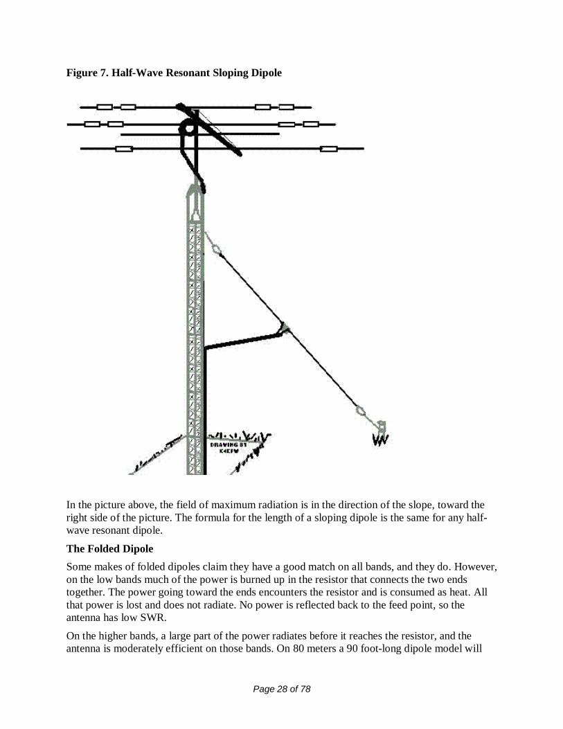
BalunsThe word “Balun” is a contraction of “balanced to unbalanced.” It is pronounced “bal un,” like“bal” in “balanced and like “un” in “unbalanced”. (Some hams mistakenly pronounce an “M” atthe end of the word making it “balum.”)A balun transforms the unbalanced transmitter output to a balance feed- line such as ladder-line.It is also used to connect an unbalanced feed-line such as coax to a balanced dipole. In the lattercase, the balun is located at the antenna feed-point and is constructed so the balun takes the placeof the center insulator.There are two kinds of baluns: voltage baluns and current baluns. They both accomplish thesame thing; the difference is in the way they are wound.A voltage balun produces equal voltage with opposite polarity at its output. As its name implies,a current balun provides equal current with opposite polarity at its output.

Page 25 of 78
Running the coax through ferrite beads can make a 1-to-1 current balun. In addition, you canbuild a 1-to-1choke current balun by winding 8 to 10 turns of coax around a two-liter soda bottleand placing the coiled coax at the antenna feed-point.Any balun is designed to “divorce” your antenna from the feed line. It is used to preventcommon mode radiation from coax, which makes the coax act as part of your antenna. You wantthe coax to be able to deliver all your power to the radiator itself. A choke balun does thisperfectly, without using any ferrite beads or toroids. In most cases, common mode coax radiationdoes not occur when a balun is not used, but to be safe it is preferable to use one.
Other baluns provide a step-up or step-down impedance transformation. A 4-to-1 balun steps upthe impedance four times. It will transform a 50-ohm impedance to 200 ohms. This type of baluntransformer is used at the output of tuners to increase the tuning range of a tuner 4 times. If atuner without a balun can match 500 ohms, a 4-to-1 balun will increase the range of impedancesit can match to 2000 ohms.Many hams think the 4-to-1 balun is used to match 50 ohms to 450-ohm ladder-line but it is not.It would take a 9-to-1 balun to match 50 ohms to 450 ohms, and it is not important to match theimpedance to ladder-line.
A balun should always be placed at the input end of ladder-line or open wire feeders to preventfeed-line radiation. A step-up balun is commonly used when using ladder-line, although a 1:1balun will work.
OTHER TYPES OF DIPOLESA Shortened Dipole Using Loading CoilsIf you are unable to put up a full-sized dipole on your property, putting loading coils into thedipole could shorten the antenna. A short antenna has capacitive reactance, and the capacitivereactance can be tuned out with a coil. The overall length of the shortened antenna will bedetermined by the amount of inductance in the coil. Pre-tuned antennas of this type are availablefrom some manufacturers.The main problem with loaded antennas is they are very narrow banded. If the loading coils arewound with small diameter wire, the coils may introduce unwanted loss into the antenna.Loading coils can also be found in shortened vertical antennas for high frequency (HF) mobileuse.

Page 26 of 78
Figure 5. A Shortened Loaded Dipole
All-Band DipoleIn the figure below, a dipole is cut to a half wave on the lowest band you want to operate.Feeding it with ladder-line and a tuner makes it possible for you to work all the other higherbands. The only losses in this antenna system are the loss in the tuner and the very small loss inthe ladder-line. This system is more than 90% efficient.As mentioned above, the balun in the tuner will be used, or if your tuner doesn’t have a balun, anexternal balun can be connected between the tuner and ladder-line with a short run of coax. Four-to-one baluns are most commonly used for this arrangement.

Page 27 of 78
Figure 6. All-Band Dipole
The Sloping DipoleA lower angle of radiation can be achieved by tying one end of a half-wave dipole to a highsupport and the other end near the ground. It is fed with or without a balun with 50-ohm coax.
The sloping dipole will show some directivity and have low angle gain in the direction of theslope. More directivity can be gained if the dipole is strung from a tower, and the tower is actingas a passive reflector. The sloping dipole is mostly a vertically polarized radiator and it workswell for DX.
Since the sloping dipole is fed in its center, it does not need to be grounded to the earth as aquarter-wave vertical does. Make sure the bottom end of a sloping dipole is at least 10 feet aboveground because, like all dipoles, there is high RF voltage on its ends.
Page 28 of 78
Figure 7. Half-Wave Resonant Sloping Dipole
In the picture above, the field of maximum radiation is in the direction of the slope, toward theright side of the picture. The formula for the length of a sloping dipole is the same for any half-wave resonant dipole.
The Folded DipoleSome makes of folded dipoles claim they have a good match on all bands, and they do. However,on the low bands much of the power is burned up in the resistor that connects the two endstogether. The power going toward the ends encounters the resistor and is consumed as heat. Allthat power is lost and does not radiate. No power is reflected back to the feed point, so theantenna has low SWR.
On the higher bands, a large part of the power radiates before it reaches the resistor, and theantenna is moderately efficient on those bands. On 80 meters a 90 foot-long dipole model will

Page 29 of 78
produce a signal at least 10 dB lower than that from a resonant dipole.If you remember the single channel TV antennas used years ago, the driven element was a foldeddipole. Folded dipoles are very broad-banded. That is the reason they were used for TV antennas,since a TV channel is 4 MHz wide.
When constructing a folded dipole, the formula for calculating the length of it is the same as forany dipole. The folded dipole consists of two parallel conductors with the ends tied together. Theconductors can be spaced from less than an inch to more than two inches apart when made fromTV ribbon or ladder-line. At the ends, strip the insulation back several inches, Twist the barewires together, solder them, and run them through insulators. The feed-point is in the center ofonly one of the two parallel conductors.
Figure 8. Folded Dipole
The feed-point impedance of a folded dipole at resonance is close to 300 ohms resistive, and canbe fed directly with 300-ohm TV twin-lead or a tuner with its balun.This antenna was very popular years ago when coax was expensive and 300-ohm TV twin-leadwas relatively cheap. A length of 450-ohm can be substituted for the twin-lead. An alternate feedmethod is placing a 6:1 balun at the feed-point and then feeding it with 50-ohm coax.
The folded dipole will not radiate its second harmonic, so it is not good for a multi-band tuner-fed antenna.
Another folded dipole type is the three wire folded dipole. We have seen this dipole only in

Page 30 of 78
books and do not know anyone who uses one. The feed-point impedance is 600 ohms resistive,and is fed with home-built 600 ohm open wire feeders.
The Double Bazooka DipoleFigure 9. Double Bazooka Dipole
The double bazooka is claimed by its users to be broad-banded, a quality especially interestingfor those hams operating on 75/80 meters. Tests done at ARRL have shown the double bazookais only slightly more broad-banded than a regular dipole, probably due to the use of a largeconductor (coax) for the center part of the antenna. The double bazooka will not transmit itssecond harmonic, and its users say it does not need a balun. Other users say it is quieter than aregular dipole.The center of the antenna is made from RG-58 coax. To find the length of coax needed, divide325 by the frequency in MHz The coax forms the center part of the double bazooka and a pieceof number 12 wire on each end completes the antenna.
The length of each of the end wires is found by dividing 67.5 by the frequency in MHz Toincrease the bandwidth, some builders use shorted ladder-line in place of the number 12 wire,which makes the end pieces electrically larger.The feed-point of the double bazooka is unique.
At the center of the coax dipole, remove about 3 inches of the plastic covering, exposing theshield. Cut the shield in the center and separate it into two parts. Do not cut the dielectric or thecenter conductor. Leave the center conductor with its insulation exposed.On the feed-line, strip off about 3 inches of outer insulation, separate the shield from the centerconductor, and strip about one inch of the insulation from the center conductor.

Page 31 of 78
To attach the feed-line, solder the two exposed feed-line conductors to the two pieces of theseparated exposed shield of the dipole center. (It goes without saying that you must seal the feed-point to prevent water from getting in.)The coax is stripped back at each of the two ends of the coax forming the center of the antenna,and the center conductor and shield are shorted together and soldered. The end wires are solderedto the shorted coax ends, then run to insulators at the end of the antenna. The soldered joints aresealed against the weather.
Broad-Banded Coax-Fed Fan DipoleA broad-banded dipole for 75/80 meters can be constructed by attaching two equal-lengthdipoles to the center feed-point and spreading the ends about 3 feet apart using PVC water pipeto separate them. The completed dipole looks like a bow tie.This makes the antenna to appear electrically to have that of a large diameter conductor. Becauseof this, the overall length will need to be shorter than a single wire alone. (When we used theantenna, we found a length of 110 feet would cover most of the 75/80-meter band without atuner.)It is fed with 50-ohm coax. The use of a balun is optional. The antennas for most of the higherbands have enough bandwidth so they do not need broad banding.
Figure 10. Broad-Banded Fan Dipole for 80 Meters
Two-Element Collinear DipoleThe two-element collinear dipole is a full-wavelength antenna having a two-dBd gain. It can befed with ladder-line and a tuner and used as a multiband antenna, or it can be fed with a quarter-

Page 32 of 78
wave-matching stub with 50-ohm coax cable to make it a single band array.In the stub matching system, a quarter wavelength of ladder-line is connected across the centerinsulator and the opposite end of the ladder-line is shorted. A shorted quarter-wave piece of feed-line acts like an open circuit.
Going from the shorted end of the ladder-line toward the dipole, there will be a point where apiece of 50-ohm cable will find a perfect match. The 50-ohm feed-point will have to be foundempirically (by trial and error.)
Figure 11. Two Element Collinear Dipole
Four-Element Collinear DipoleThe four-element collinear dipole array consists of four half-wave segments connected end-to-end with an insulator between each two adjoining segments. The feed-point is at the center of thearray. The antenna is fed with ladder-line through a tuner.A quarter wave shorted ladder-line stub hangs down vertically from the insulators between theinside and the outside half-wave segments. This stub provides a 180-degree phase shift so that allhalf-wave segments are fed in phase.
This antenna has a 6-dBd gain, and it radiates bi-directionally at an angle perpendicular orbroadside to the plane of the wires.
This antenna is too long for most hams to use on 80 and 40 meters, and the stubs hangingvertically will be too close to the ground. For 20 meters, the four-element collinear array will be97 feet long and the stubs will be 18 feet.To find the length of each half-wave segment, divide 468 by the frequency in MHz, and for the

Page 33 of 78
quarter-wave stubs, divide 246 by the frequency in MHzThis antenna is easy to build. All you need is 5 insulators, antenna wire, and some ladder-line.
It will have no gain if you use it on bands for which it is not designed, because the stubs are usedas phasing lines. It is definitely not a multiband antenna.
It is possible to add more half-wave segments to the ends of this array to make it have 6, 8, 10,etc. half wave segments. Adding more segments will add more gain and make the lobesnarrower.
Figure 12. Four-Element Collinear Dipole
Coax-Fed Dipoles Operated on Odd Harmonic FrequenciesAntennas fed with 50-ohm coax can be used on other bands for which they are not cut.
An 80-meter dipole will have a relatively low SWR and will be resonant at a single frequency on10 meters and not much power will be lost in the coax even if operated off resonance. A 40-meter dipole will work the same way on 15 meters.Using coax, a dipole will work on its fundamental frequency and on odd-harmonic frequencies,and it is not necessary to use ladder-line.The fundamental frequency is the frequency for which the antenna is a half-wavelength long, andthe odd harmonics are 3 times, 5 times, 7 times, etc. the fundamental resonant frequency. Afrequency of 21 MHz is 3 times or the third harmonic of 7 MHz, and 28 MHz is the seventhharmonic of 4 MHzAntennas operated on their odd harmonics will be resonant a little higher in frequency than exactmultiples of their fundamental frequencies.Since the odd harmonic antennas input impedance is higher than it is on its fundamentalfrequency, many amateurs use a series quarter-wave matching section of 70-ohm coax to give ita better match.
The 80 meter inverted-V dipole in use here has a 2:1 SWR on 10 meters indicating it has an

Page 34 of 78
impedance of around 100 ohms. However, modeling the antenna for 10 meters shows theresonance to be below 28 MHz, probably because the antennas fundamental resonant frequencyis 3920 instead of 4000 kHz. A quarter wave 70-ohm matching section should bring the SWRdown to a much lower level.
As said earlier, if you try to use coax with a dipole on its even harmonic frequencies, the feed-point impedance will be very high, the SWR will be extremely high, and the coax will absorbmost of the power. In addition, when operating a coax-fed antenna on its even harmonics, thetuner may not be able to provide a match.
Operating any antenna on any of its harmonic frequencies, odd or even, will work better if it isfed with ladder-line and a tuner.
Figure 13. Three Half-wave Dipole
This antenna is matched by a quarter-wave 70-ohm series matching section. Three half waveswill resonate higher than you would expect because the center half wave doesn’t have to contendwith end effects.
To calculate the length of a three half-wave dipole, divide 1380.6 by the frequency in MHz Fivehalf waves is found by dividing 2316.6 by the frequency.
To use a 3 half-wave antenna on 15 meters, the 70-ohm matching section needs to be 7 feet 7inches and the antenna needs to be 64 feet long for a good match. It will be just a little long on40 meters. When using a 40-meter dipole with a 15-meter quarter-wave matching section, it will

Page 35 of 78
still have acceptable SWR on 40 meters.
Figure 14. Radiation Pattern of a 15- Meter Three Half-Wave Dipole at 65 Feet
The pattern shows 6 lobes, 4 major lobes and 2 minor lobes. The vertical radiation pattern showslow angle radiation.

Page 36 of 78
All Band Random Length DipoleA random length of wire cut into two pieces can be used as a dipole, and it will radiateefficiently. It has to be at least a half-wave length on the lowest band you want to work. It looksthe same as the all-band dipole and is the same, except it is not resonant on any band. Therandom length dipole is being described here to emphasize that the radiating part of an antennadoesn’t have to be resonant.
Because it will have a feed-point impedance that is unusual, it must be fed with ladder-line atuner, and a balun. Since you are using a tuner, it can be used on multiple bands.
If you make it very long, it can have gain over a dipole. For example, if it is four wavelengthslong, it will have 3-dBd gain. As you move to higher bands, the electrical wavelength of theantenna increases, and each higher band will have more gain.A half-wave antenna radiates perpendicularly to the plane of the wire. As you move to higherbands, this antenna begins to show some gain, and instead of two lobes of radiation, the twolobes split into four lobes and the pattern resembles a four-leaf clover.
As you make the antenna longer, the four lobes move nearer to the ends, the gain increases, andthere are minor lobes of radiation between the major lobes. These minor lobes make it possibleto work in all directions. The longer the wire, the closer the antennas major lobes radiate bi-directionally toward its ends
Figure 15. All Band Center-Fed Random Length Dipole
The problem with using a random length of wire for this antenna is you may find that, because oflimitations of your tuner, you may not be able to tune a particular length of antenna on somebands.

Page 37 of 78
Certain lengths will tune all bands, and one of those lengths is 135 feet. That particular lengthwill be nearly resonant on all bands of 80-10 meters. Resonance only makes it easier to tune, butit has no effect on efficiency. A length of 260 feet will tune from 160-10 meters. Some hams userandom lengths of wire without problems, while others have had problems with random lengths– which often can be solved by changing the length of the dipole wire. If you plan to put up thisantenna using a random length of wire, you will need to experiment with various lengths untilyou find a combination that works.
A Two-Band Fan DipoleA two-band dipole can be constructed by connecting together the feed point two dipoles for evenharmonically related bands. It is fed with 50-ohm coax with or without a balun. The bestexample of this is 80 and 40-meter dipoles connected together.Both dipoles are cut for half-wave resonance on each of the two bands. They are fed together andthe ends of the wires are spread apart. If the ends are close together, there will be interactionbetween the dipoles.
In such an antenna system, both dipoles must be carefully pruned for lowest SWR one band at atime. The lower band will be tuned first since the shorter dipole will not interact with the longerone.Each dipole has a low antenna resistance on the band for which it is resonant. RF energy followsthe path of least resistance, and it automatically selects which dipole will receive power. Theremaining antenna will have a high impedance.
High impedance will block RF. Such an antenna will have a narrower bandwidth than a singleband dipole, but close to the resonant frequency of each dipole, a tuner will not be needed.
To connect many dipoles for multiple bands is possible, but it is not recommended becausemultiple wires are prone to interact and it will be impossible to achieve a low SWR on somebands. However, on the two band model, the 40-meter dipole will resonate close to 15 meters,the 80-meter dipole will resonate close to 10 meters, and working four bands with this set-up ispossible.Some hams are using this antenna successfully with a tuner on all bands, although the signal on20 meters suffers somewhat because of high SWR.

Page 38 of 78
Figure 16. Two-Band Fan Dipole for 40 and 75 Meters
Trapped Dipole for 75 and 40 MetersA trap is constructed from a capacitor and an inductor connected in parallel. It acts as an openswitch on the frequency for which it is resonant. A trap is placed on each side of the dipole.For a 75 and 40 meter trapped dipole, the traps must be resonant on 40 meters, and each trapshould be placed a quarter wave from the center insulator. The center section between the traps iselectrically isolated from the ends of the dipole by the traps on 40 meters, and the center sectionof the antenna becomes a full-sized half wave resonant dipole for that band.This antenna is fed with 50-ohm coax and an optional balun. Wires connected to the outside ofthe traps are run to the end insulators and are tuned so the entire antenna resonates on 75 meters.The 75 and 40 meter trapped dipole will be shorter than a 75-meter dipole, because the inductorin the 40-meter trap acts as a loading coil on 75 meters.In addition, the ends of the antenna can be tuned to operate on the 80-meter CW band instead ofthe 75-meter voice band.Several sets of traps can be inserted at the correct points in the dipole to make a multi-banddipole. Multi-band trapped dipoles are being sold, but in many cases they will require the use ofa tuner. If a good match is found at a frequency on some bands, the bandwidth without a tunerwill be very narrow.

Page 39 of 78
Figure 17. Trapped 75 and 40-Meter Dipole
The antenna is only 108 feet long instead of 120 feet because of the loading effect of the traps on75 meters. These dimensions are for antennas using the traps made by W2AU. If you use otherbrands of traps, the length of the end wires will have to be adjusted. What you do in that case ismake the wire long, measure its resonant frequency on 75 meters, and prune the ends toresonance at your favorite frequency.
The Extended Double Zepp DipoleAn extended double Zepp is a long dipole with 3-dBd gain. It is the longest dipole antenna,which will radiate at right angles to the plane of the antenna. To find the overall length of anextended double Zepp, divide 1197 by the frequency in MHz. Each leg of the antenna is 0.64wavelength long, and the total length is 1.28 wavelengths.
An extended double Zepp for 75-meters at 3.8 MHz is 315 feet. Not many amateurs have spacefor that antenna.
The extended double Zepp is mostly fed with ladder-line. Another method of matching anextended double Zepp is to use tuned lengths of 450-ohm ladder-line as a series matchingtransformer connected between the 50-ohm coax and the dipole. The length of the matchingsection of 450-ohm ladder-line can be found by dividing 135 by the frequency in MHz

Page 40 of 78
Figure 18. Extended Double Zepp Dipole
The G5RV DipoleAn interesting antenna that will work somewhat on all high-frequency bands is the so-calledG5RV antenna, named for the call letters of Louis Varney (SK) who designed it. It is a 102-footlong, or three half-wavelength dipole antenna on 20 meters (14.150 MHz), and can be used witha tuner on other bands as well.In his original design, Varney calculated the length to be 102.57 feet, but chose to make it aneven 102 feet since a tuner was going to be used with it anyway. It was originally fed through a34-foot 500-ohm homebrew open wire matching section from a 70-ohm coax or parallelconductor feed-line.The 34-foot open wire line is a half wavelength on 20 meters, and at the end of a half-wave feed-line you will see the antennas impedance repeated regardless of the feed-line impedance. Theladder-line helps to partly match the antenna on the other bands.
The G5RV antenna is around 20 feet short of being a half-wave on 80 meters, and on bands on20 meters and up, it has theoretical gain. We believe that gain is negated by losses in the coax ofthe feed system, except for 20 meters.At the frequency of the best match, commercially made models of the G5RV are said to have a

Page 41 of 78
1.8:1 SWR on 80 meters.Where the coax joins the open wire, Varney recommended using a choke made of 8 to 10 turnsof coax. He advised against using a balun, because an SWR of 2:1 or higher may cause the balunto heat and possibly burn out. The SWR will be moderately high or high on bands other than 20meters.Varney recommended using the lowest loss coax available, and as short a run as practical,because of feed-line losses caused by high SWR. This recommendation is still very importanttoday.
Some G5RV antennas put out decent signals, while others have relatively weak signals –possibly because some are using lossy coax and baluns while others are not. The height aboveground may also play a part in how well it works.Some G5RV antennas today use small diameter 50-ohm coax and 450-ohm ladder-line, with abalun between the ladder-line and the coax, contrary to Varney’s suggestions. There are severalvariations of the G5RV antenna being sold. If you use one, a tuner will be required.
The G5RV shown below is close to the original version. It uses 36 feet of 300-ohm TV ribbon,but modern designs of this antenna use 34 feet of 450-ohm ladder-line. These variations workwell when used with a tuner. It is shown in the inverted-V configuration, but it could be put up inthe flattop configuration with no modification.

Page 42 of 78
Figure 19. G5RV Dipole
Off-Center Fed DipolesA long dipole consisting of multiples of equal half-wave segments is normally fed in the centerusing ladder-line. Dipoles do not necessarily have to be fed in the center. They can be fed in thecenter of any one of these half-wave segments, even fed off-center. A fair match will occur ifcoax is used.

Page 43 of 78
Figure 20. One wavelength Off-Center-Fed Dipole
The dipole shown above is a one-wavelength dipole. It is nothing but two half-waves end to end.It is being fed in the center of one half-wave segment, or a quarter wave from one end. It ispossible to make it any number of half waves, and if it is fed a quarter-wave from one end, it willhave a fair match. The way shown above is an example of how to feed an antenna with evenmultiples of a half wave using coax. A 2:1 or 4:1 balun will improve the match on longerversions.
The Windom antenna is another example of an off-center fed antenna. The original Windom wasfed off center with a single wire. The other side of the transmitter was connected to ground. Thefeed-point impedance at the transmitter was reported to be 500 ohms on all bands. The antennawas designed by William L. Everett and J.F Byrne at Ohio State University. W8GZ, whose lastname was Windom, described the antenna in the September 1929 issue of QST.A lot of research on modern variations of the Windom antennas has been done, including theones described by Fritzel, the Carolina Windom. The main differences are slight differences inthe position of the feed-point and the impedance of the baluns used for matching.
Windoms are sensitive to the height over ground, meaning the height above ground affects theSWR. The offset position of the feed-point will also determine the feed-point impedance.
Two variations of Windoms have vertical radiators, and one has two pieces of transmission linein series; the upper piece is connected to the dipole, and the lower piece is connected to thetransmitter, with the feed-point of the dipole placed off center.

Page 44 of 78
Figure 21. Carolina Windom
A variation of the Windom dipole is the Fritzel antenna, named after its inventor andmanufacturer, Dr. Fritz Spillenger (SK), a German ham, call sign DJ2KY. The Fritzel’s shortside is 0.18 wavelength long and its long side is 0.32 wavelength long. It is fed with coax and a6:1 balun. Theoretically, the feed point impedance is 300 ohms, and the balun provides a 50 to300 ohm impedance transformation.
Modeling the antenna on its lowest resonant frequency at 35 feet, it shows about 120 ohmsimpedance. The original Fritzel antenna being used by K4LMS reportedly will work all bandswith a tuner, but it will work 40, 20, 17, 12, and 10 meters without a tuner with an acceptableSWR. A version sold commercially uses a 4:1 balun, with the feed-point at a slightly differentlocation, as shown below.
Page 45 of 78
Figure 22. Windom Dipole (Fritzel Type)
The difference between this commercial Windom antenna and the original Fritzel is thedifference in the offset of the feed-point, and therefore the type of balun needed.
END-FED ANTENNASEnd-Fed ZeppA half-wave resonant antenna can be fed from its end. When fed this way, it is also known as anend-fed Zepp.
An end-fed Zepp will work on its fundamental frequency and on odd and even harmonicfrequencies. The name “Zepp” goes back to the days of dirigibles or Zeppelins, which usedtrailing wire antennas that had to be fed at one end.The end of a half-wave antenna has very high impedance, and an antenna fed this way is said tobe voltage-fed. Feeding a half-wave resonant dipole in the center means it is current fed.The normal way of feeding the end-fed antenna is with ladder-line. One side of the ladder-line isconnected to one end of the antenna, and the other side is connected to a short wire runningbetween two insulators.
Since the antenna is connected at its high impedance point, there will be a large current in thecenter of this antenna. No current flows from the open side of the feed-line because it is at a zerocurrent point.

Page 46 of 78
Figure 23. End-Fed Zepp
The end-fed Zepp can be matched by cutting the ladder-line to a quarter wavelength, with thebottom end of the ladder-line shorted. A certain distance above the short is a 50-ohm feed-point,which can be fed directly with coax. MFJ markets antennas of this type for single bands, and alsosell the parts so you can build your own. You will have to find the 50-ohm point by trial anderror.This method of feed makes it a single-band antenna.

Page 47 of 78
Figure 24. Alternate Method of Feeding an End-Fed Zepp
End-Fed Random Length AntennaBelow is another end-fed antenna made from a random length of wire connected to the back ofthe tuner. The wire then exits the shack and goes to a high support, from which it runshorizontally to another high support.The tuner’s ground side must be connected to a good RF ground, since a poor ground causeshigh losses.This antenna is commonly called a “long wire.” Since the end of the antenna comes in the shack,you will be exposed to high levels of RF.In addition, this type of installation may cause RF to be picked up in the microphone, causingdistortion.
The feed-point of the long wire connected directly at the output of the tuner can have animpedance of a few ohms to a thousand ohms, depending on the antenna’s length. If the wire iscut to a multiple of a half wave at the lowest frequency the system will be efficient, since it is fedat a voltage point and very little current flows into the ground.
This antenna is really a variation of an inverted-L fed directly without a feed-line from the tuner.

Page 48 of 78
Figure 25. End-Fed Random length or Long-Wire Antenna
THE HALF SLOPERThe Half-SloperThe half sloper is an antenna that is hard to categorize, since it is not a sloping dipole and it is nota vertical. The half sloper is half of a sloping dipole.
To make one of these antennas, cut a quarter-wave radiator by dividing 234 by the frequency inMHz and tie an insulator to both ends. One insulator is tied near the top of a tower and theradiator wire is run down toward the ground.Coax is split into its center conductor and shield, and it connects across the insulator at the tower.The center conductor of the coax is tied to the quarter wave radiator and the shield is grounded tothe tower. This means the tower is acting as the missing half of the dipole.It is a difficult antenna to get a good match, because the height above ground of the feed-pointand the angle of the slope affect the impedance.Some users of this antenna say to mount the feed-point at 45 feet up on the tower and have abeam antenna on the tower above the feed-point to use as a counterpoise. Other users say youmust find the 50-ohm point on the tower, which is a tedious task.
The half-sloper is used almost exclusively on 80 and 160 meters. The half sloper is mostlyvertically polarized and it is directional toward the slope.

Page 49 of 78
It has also been said, “Some installations work super, while others do not work well at all.” Onehalf sloper tried here had disappointing performance. The signal was at least 10 dB below adipole, and the SWR was high.
Figure 26. Half-Sloper
VERTICAL ANTENNAS
Why Verticals Are UsedVertical antennas have the radiator mounted at right angles to the earth. The vertical is usedwhenever you desire to radiate your signals in all directions at a low angle. Low angle radiationis needed to work DX effectively.
Radio waves travel to the ionosphere, where they are reflected to hit a point near the horizon,reflecting farther around the curvature of the earth. For a dipole to radiate a strong signal at lowangles, it has to be more than a wavelength above ground. A low dipole is not particularly a goodDX antenna for 80 and 160 meters. (However, the average dipole at modest heights willoutperform any ground-mounted vertical having a poor ground system.)Vertical antennas work very well at low frequencies, but ground losses increase as we movehigher and higher in frequency. (See the section concerning ground-wave propagation.) Verticalantennas, because they are unbalanced antennas, do not need baluns. They are normally fed with

Page 50 of 78
coax.If a ground mounted, quarter-wave vertical is all you can put up at your location (QTH), then useit. However, it will be a mistake to put up this antenna if you are not be able to install a groundradial system; in that case, you probably should put up a dipole. Most ground mounted quarter-wave verticals manufactured today are trapped in order to work multiple bands.The ground-mounted vertical also needs to be put out in the clear, away from RF-absorbingobjects. This does not apply to half-wave verticals, which are different animals, nor to highquarter-wave verticals using elevated radials.
The approximate length of a full-sized resonant quarter wave vertical can be found by dividing234 by the frequency in MHz. Note: 234 is half of 468, the number we used to calculate thelength of a half-wave antenna. The actual length for resonance may be a little different fromwhat you calculate, because of the diameter of the vertical element.
Trapped verticals are physically less than a quarter wave in length because the traps load them.The vertical is fed at the bottom, where it is insulated from the ground. The center conductor ofthe coax connects to the vertical element, and the shield is connected to the ground system.

Page 51 of 78
Figure 27. Ground Mounted Trapped Vertical
Disadvantages of Using Quarter-Wave VerticalsThe most obvious disadvantage of using any vertical antenna is that on 80 meters it has less thanthe optimum high-angle radiation needed to work stations within a few hundred miles.
Ground-mounted quarter-wave verticals use a ground system for the other half of the antenna,and the ground system losses can be very high. The ground wave signal should eventually radiatein space at angles at the horizon, but since there are very high losses in the ground wave atamateur frequencies, a ground-mounted vertical has almost no signal down near the horizon. Atangles below 10 degrees, the signal will be greatly attenuated.A ground-mounted quarter-wave vertical with an ideal ground should have an impedance of 35ohms resistive. If you were to measure its impedance see 60 ohms resistive on an antennaanalyzer, it means it has a loss resistance of 25 ohms. That loss resistance is mostly in the groundsystem. Under these conditions, only 58% of the power will radiate as RF, although you willhave a 1.3:1 SWR. Forty-two percent of the power will be turned into heat by the loss resistance.
With the feed-point being at ground level, some more loss comes from the radiated wave beingabsorbed by power lines, trees, and buildings with its associated wiring. That loss does not show

Page 52 of 78
up in antenna analyzer measurements.The best ground system for a ground-mounted vertical is 32 to 120 wires, called “radials,”radiating from the feed-point like the spokes of a wheel. These radials need to be a quarter wavelong. At the feed-point, the radials are bonded together and are fed from the shield side of a coaxcable.Not many amateurs have the resources to build such a ground system. Many short radials will bemore effective than a few long ones. When using a ground mounted vertical, many hams drive an8-ft. ground rod into the earth for their ground system. The ground losses are very high in thatcase. Using a ground rod for the ground system of a vertical antenna confirms the old adage:“Verticals radiate poorly in all directions.”
To eliminate ground losses, you can use an elevated quarter-wave vertical with an elevatedground system called a “ground plane.” The ground plane vertical, as this arrangement is called,must be mounted high enough to prevent the return path from coming back through the earthground.
Ground plane verticals should be mounted above nearby objects that absorb RF. They will benearly 100% efficient if they are high enough. The ground plane consists of two or more radials,but most ground planes have three or four per band. The ground plane radials do not have to beresonant, but should be at least a quarter-wave long.
An elevated ground-plane vertical will be more effective for working DX than a dipole.
Long and Short VerticalsVerticals can be less than a quarter-wave in length. They can be loaded by coils or linear loadingsections, or a short vertical can be fed directly with a tuning unit at the feed-point. The lossresistance in a short vertical may be appreciable.Since the radiation resistance is very low at the feed-point of a short vertical, the current at thefeed-point will be very high. The more current that flows into loss resistance, the higher the losswill be.
Any coils used in the tuning unit and for loading should have as heavy a conductor as possible,since these can cause appreciable loss when the current is high. This is also true for the groundsystem.The loss described here is called “I squared R loss”, which means the loss in watts is found bymultiplying the current times itself and then multiplying that answer by the loss resistance. Thatmeans if the current into a lossy antenna system is doubled, the power lost in watts is increasedfour times. Making a vertical very short and tuning it to resonance with an inductor will alsoresult in an antenna with a very narrow bandwidth.
A more subtle loss of energy in very short vertical antennas is coronal discharge from the tip endof the vertical. Corona occurs when the voltage is very high at the end and electrons flow outinto the air. (This can be visible at night if the transmitter power is high and you are at a highaltitude.) Power is lost from the antenna when corona is produced because corona is a form oflight, and light is another form of energy.You can realize up to a 1.5 dBd gain from a vertical antenna by making it longer than a quarterwave, but there is a limit to how long to make it and still get low angle radiation. That limit is

Page 53 of 78
5/8th-wave.To find the length of a 5/8th-wave vertical, divide 585 by the frequency in MHz. For example, tocalculate the length of a 5/8th-wave vertical for 20 meters (14.000 MHz) divide 585 by 14.0. Itequals 41.786 feet or approximately 41 feet 9.5 inches.
A tuning unit will be needed at the feed-point of this antenna, as the impedance of a 5/8th-waveantenna is low and high current will flow into it. A tuning unit will usually have enoughbandwidth to cover the entire band on each band of 20 meters and higher.A tuning unit is also called a matching network. It is similar to an antenna tuner, but has fixedinductors and capacitors. Tuning units for 80-and 160-meter verticals will cover only a portion ofthe bands.
Outside the bandwidth limits of the tuning unit, you can use the tuner at the transmitter end.Radials or ground planes are needed for a 5/8th-wave vertical, and they need to be a quarterwave long.The impedance of a half-wave antenna is high if fed at its end. An end-fed half-wave verticalwill have a small amount of gain over a quarter-wave vertical. This antenna does not have theground losses of a quarter-wave vertical because it is fed at a high impedance point and thecurrent flowing into the ground is negligible.Commercially made resonant half-wave trapped verticals are end fed at the bottom. A built-inmatching network is found at the base, and several very short radials are mounted below thefeed-point to de-couple RF from the feed-line. These antennas should be mounted as high aspossible, away from RF-absorbing objects.Because the ground losses are lower, a half-wave vertical will outperform a quarter-wave verticalby several dB, and in some cases many db.
The Inverted-L VerticalThe inverted-L antenna is a wire vertical antenna with part of the top end bent horizontally. Itresembles an “L” turned upside down.
The inverted-L is used to reduce the height required by a vertical and still keep the antennaresonant and full sized. It is fed at the end at ground level the same way a ground mountedvertical is fed, and all the losses we described for a ground-mounted vertical apply here.Some current flows in the horizontal part of the inverted-L, and for that reason it has both strongvertical and weaker horizontal polarization.If you make it a half-wave antenna you won’t need a good ground, because negligible currentflows into the ground. A half-wave inverted-L antenna needs to be fed with 50-ohm coax and atuning unit.
An inverted L for 160-meters is usually made of wire one-quarter wavelength long, or about 127feet. It runs vertically from near ground level to the top of a support, perhaps 60 or 70 feet. Thenthe end runs horizontally to a nearby support.The antenna is coax-fed at ground level between the vertical section and ground system acrosssome type of insulator. A matching network at the feed-point will be required if the impedance isnot equal to 50 ohms.

Page 54 of 78
Figure 28. Inverted-L
The picture shows an inverted-L running up the side of a tower. The feed-point is at groundlevel, with the center conductor of the coax attached to the bottom end of the wire. The coaxshield connects to a ground system of radials.The total length of wire used in this antenna is half of what is needed for a dipole, since the otherhalf of the antenna is the radial ground system.The inverted-L is used mostly on 160 meters, but some have been built for 80 meters. Theinverted-L antenna can also be cut for a half-wave to reduce ground losses.
Vertical Mobile AntennasThe mobile antenna, being so short, has a large capacitive reactance. A coil is inserted in theantenna to provide an equal amount of inductive reactance to make it resonant. A coil of thistype, carrying a large amount of antenna current, causes some loss resistance in the system. Toreduce losses in the coil, wind it with a conductor as large as practical. (That’s exactly whatsome mobile antenna manufacturers have done.)The sources of loss in mobile antennas are in the coil losses, losses in the conductors making upthe radiating part of the antenna, corona discharge, and the ground loss from the vehicle onwhich it is mounted. However, because of the large amount of metal in the body of the vehicle,

Page 55 of 78
the ground losses are not as high as the losses from ordinary ground mounted verticals.Matching transformers are available that step down the impedance of 50-ohm coax to the verylow impedance of the loaded vertical. It is generally preferable to use a transformer rather thanrely on the internal tuner of the transceiver.
Some low priced single-band mobile antennas are constructed using a polymer shaft and a small-gauge wire encapsulated in polymer material running beside the shaft. The loading coil made ofthe same wire is also encapsulated in the polymer. The small wire, because of its size andbecause it carries a large RF current, will lose a lot of power as heat. This type of mobile antennais rated for 200 watts.All mobile antennas have corona loss. Corona will not be visible unless you run high power andafter dark. Many amateurs don’t believe it’s there because they can’t see it.Ground losses from the vehicle’s body diminish with increasing vehicle size. This is why 18-wheeler hams have such big mobile signals.To diminish the ground losses on any mobile installation, you should use as large as a conductoras possible to bond the coax shield to the vehicle body. All metal parts of the vehicle’s body,fame, and drive system need to be bonded together with heavy ground straps.
To make the mobile antenna system more efficient, use an antenna with an adjustable inductorand use as long a “stinger” as practical above the coil. You will increase the radiation resistanceby using a longer stinger, and then the loss will be less because you will require less coilinductance.
The ratio of radiation resistance to loss resistance becomes larger by raising the radiationresistance and reducing the loss resistance.
As we said earlier, the efficiency of any antenna system is found from the ratio of radiationresistance to total resistance, or radiation resistance divided by total resistance times 100%. Thetotal resistance is equal to all the loss resistances plus the radiation resistance.Some HF mobile antennas use motor-driven variable inductors. These antennas are known as“screwdriver antennas.” A control cable is run from the motor to a switch at the operator’sposition in the front of the vehicle. Because a mobile antenna has a very narrow bandwidth, youmay have to tune it often as you move frequency (QSY).(This is still preferable to the old days when we had to get out of the vehicle to make changes inthe length of the stinger when the frequency was changed.)Mobile antennas for 20 through 10 meters do not require the care in installation that is needed for160, 80, and 40 meters, because the length of a mobile antenna becomes closer to a quarter waveas you move to higher bands. The radiation resistance increases on each higher band.
While moving to higher bands, less inductance is needed to tune the antenna, and that lowers theloss resistance.
A 96-inch mobile whip is just a couple of inches short of being a quarter wavelength on 10meters, and a loading coil is not needed there. The band that has the least mobile antennaefficiency is 160 meters. If you reach a radiation efficiency of 2% on 160 meters on your mobileinstallation, you will be doing well.

Page 56 of 78
The efficiency of the best 75-meter mobile antenna is from 5% to 10%. In using the best mobileantenna on 75 meters, a 100-Watt mobile rig will radiate 10 watts at most. The rest will beconverted to heat.To increase the efficiency of mobile antennas:
· Place the loading coil about half way from the feed-point to the antenna tip. Efficiencydecreases if you put the coil above or below this point.
· Mount the antenna as high up on the vehicle as possible. This reduces the ground lossesbecause it reduces the capacitance of the antenna to ground.
· Use a loading coil with a Q as high as possible. See the ARRL Handbook for a discussionof coil Q.
· Make the antenna as long as possible. Note: long antennas are prone to strike tree limbsand bridge overpasses.
· Increase the size of the mast between the loading coil and feed-point.
· Put a capacity hat above the loading coil. The capacity hat reduces the number of coilturns needed to resonate the antenna.
· Make the coil with as large a diameter wire possible. This decreases the coil loss, whichis a large part of the total loss of a mobile antenna.
Any changes in the antenna system that raise the radiation resistance will increase the efficiency.
ONE-WAVELENGTH SINGLE LOOP ANTENNASThe Horizontally Oriented LoopTo calculate the length in feet of any one-wavelength loop, divide 1005 by the frequency inMHz.
Horizontally oriented one-wavelength loop antennas have become very popular on 160, 80, and40 meters and it is one type of NVIS antenna. (NVIS stands for “near vertical incidenceskywave” because of its high angle radiation pattern.)Users claim that the loop antenna is quieter than other antennas. This is because it doesn’t pickup the noise from power lines, thunderstorms, etc., coming in at low angles.
These antennas radiate on their fundamental frequencies with a broad pattern straight, causingsome to call these antennas “cloud warmers.”
There are NVIS antennas other than loops. They are dipoles at low heights, and dipoles withparasitic reflectors placed under them to cause the signal to radiate mostly straight up.
NVIS antennas have an advantage in working nearby stations because you don’t get the staticnoise and interference from far distances. They are definitely not DX antennas.
On their fundamental frequencies, horizontally oriented loops take up half the horizontal distanceas a half wave antenna for that band.
Loops are two-dimensional antennas having depth as well as breadth. Two loop configurations

Page 57 of 78
are the square loop and the triangle loop. Some hams pull loops out in irregular shapes to fitwhere the supports are located.
The only advantage in using a rectangular loop instead of a square loop is to take up lesshorizontal space. This is true because the gain of a rectangular loop is diminished below a squareloop. The area enclosed by the perimeter of the loop determines the gain of a loop. A circularloop has the most enclosed area, but it requires an infinite number of supports.
The gain of a loop comes from the loop having two maximum current points separated by adistance of one-quarter wavelength. (From here on we will call a horizontally oriented loop ahorizontal loop.)Modeling the gain of the horizontal loop for the 80-meter band over real ground shows themaximum gain occurs with the loop at 7 meters or about 25 feet above ground. This gain isstraight up from the loop. At that height, its gain is about 9.25 dBi, which equates to about 7 dBdin free space.The gain of the loop diminishes slightly as the antenna is raised. The feed-point radiationresistance at 7 meters height is 35 ohms resistive and 0.0 ohms reactance, and you do not need amatching section of 70- ohm coax.
At a height of 10 meters or about 33 feet, the radiation resistance rises to 63.5 ohms. There theSWR will be 1.27:1, if it is fed directly with 50-ohm coax.
At 15 meters or about 50 feet, the radiation resistance rises to 118 ohms and a 70-ohm matchingsection will be in order. The gain drops to a little less than 7 dBi at that height.
These figures may or may not be applicable to your QTH, depending on your soil conductivity.As you can see from the above numbers, the feed-point resistance rises as the loop is raised.
The horizontal loops also are used on their harmonic frequencies. The loop with more gain and asuperior pattern is a two-wavelength loop. An 80-meter loop is a two-wavelength loop on 40meters. The two-wavelength loop has a lower angle of radiation, but is a very large antenna for80 meters. At 3800 kHz it has a perimeter of about 530 feet.
A two-wavelength loop is not an NVIS antenna. Using coax with a tuner is not an ideal way forworking a loop on its harmonic frequencies. This is because the high SWR in the coax on somebands will cause high loss. For example, an 80-meter loop fed on 40 meters will have an SWR of8:1 and the SWR on 20 meters will be 49.5:1. There will be some hams who will say they getsatisfactory results this way. However, theory suggests they would have a stronger signal if theyused ladder-line, which has less loss. Feeding a loop antenna with ladder-line makes more sensewhen working a loop on harmonic frequencies.

Page 58 of 78
Figure 29. One-Wavelength Horizontal Loop
To realize maximum gain, the square and triangular loops should have equal sides. When thesides are equal, the loop has maximum enclosed area for whatever configuration you use. Othershapes will work, but the gain will suffer.To support a square loop, you will need four supports, one for each corner. A triangular loop willneed three supports. Once you have cut the single piece of wire to the right length, run the wirethrough insulators in each corner, with a rope from the insulator to a support.
To make the feed-point, connect the ends of the loop to an insulator, and connect the centerconductor of the coax to one end of the loop and the shield to the other. Most hams do not feedloops with a balun at the feed-point.
The Vertically-Oriented Single Loop for 40 and 80 MetersVertically-oriented loops radiate broadside to the plane of the loop. A horizontally polarizedvertically-oriented loop has both vertical and horizontal wires.
From here on out, we will refer to a vertically oriented loop as just a vertical loop. When usingthis term, we are not referring to its polarization. If the feed-point is on one of the horizontalwires, the loop radiates horizontally polarized waves. The vertical wires radiate weaker verticallypolarized waves.

Page 59 of 78
If the feed-point is on one of the vertical wires, vertically polarized waves will be radiated. Theradiation from a one-wavelength vertical loop has both high-angle and low-angle radiation.
It is a good antenna for both nearby stations and for DX contacts. It is better than a dipole for DXbecause the vertical loop puts out a stronger low-angle signal than a dipole does.
The gain of a vertical delta loop is 4.55 dBi or about 2.4 dBd. Its feed-point impedance is about120.5 ohms. The square vertical loop has 5 dBi gain and about 2.85 dBd, and the feed-pointresistance is 143 ohms. Both square and delta vertical loops need to be fed with a series quarter-wave matching section of 70-ohm coax.
Figure 30. Single-Element Vertical Delta Loop
Square vertical loops need two support, and needs less vertical space than the delta loop. Thevertical space needed for an 80 meter square vertical loop for is 92 feet. For 40 meters, thevertical space is half that. It is rare to find someone using the square vertical loop these days.The vertical delta loop is more common because it needs only one high support. The apex of adelta loop for 3500 kHz needs to be 102 feet high, and on 40 meters, it needs to be 62 feet. Thisassumes the bottom horizontal wire will be 20 feet off the ground.
In order to make a vertical loop fit on a shorter support, the sides of the loop can be reduced inlength while making the horizontal wires longer. This will put the two maximum current points

Page 60 of 78
closer together, which has the effect of reducing the gain.Like the horizontal loop, the formulas for finding the length in feet of these loops are the same:1005ndivided by frequency in MHz.In addition, because the feed-point resistance is nearly the same as horizontal loops, quarter-wave matching sections and other methods can be used to feed the vertical loops. The verticalloop is not as sensitive to height as the horizontal loop. Both vertical square loops and verticaldelta loops can be operated on harmonically related bands.

Page 61 of 78
Figure 31. Radiation Pattern of a 30-Meter Delta Loop on 30 Meters. The Bottom Wire isat 18 Meters above Ground.
The horizontal pattern shown above demonstrates that the 30-meter delta loop has a bi-lobalpattern broadside to the plane of the loop.

Page 62 of 78
The vertical pattern below the horizontal pattern shows both high angle and low angle radiation.The angle of maximum radiation is at 35 degrees above the horizon. The angle of radiationstraight up is only down about 1.5 db. This is pattern demonstrates the vertical delta loop is goodfor both nearby stations as well as DX.
Figure 32. Radiation Pattern of a 30-meter Delta Loop on 15 Meters

Page 63 of 78
DIRECTIONAL BEAM ANTENNASThe Monoband YagiIn the 1920s, Shintaro Uda and Hidetsugu Yagi developed a beam antenna that had sharpdirectivity and high gain. Later, work was done primarily by Mr. Yagi, and Yagi was the namegiven to the antenna until recognition was finally given to Mr. Uda. Its proper name is the Yagi-Uda Array. It is often called a beam antenna.
A monoband Yagi is for a single band. Commercially made monoband Yagis are advertised ashaving dimensions tuned for maximum performance, although in fact this is not always the case.
The Yagi has two or more aluminum elements mounted on and perpendicular to a boom. Manyhams use antenna rotors to turn the antenna in the direction of the station they want to work.Most high frequency beam antennas are horizontally polarized, which means the elements areparallel to the ground. (CB beam antennas and some two-meter beams are vertically polarizedwith the elements at right angles to the ground.)A 2-element Yagi has a gain of around 3 to 4 dBd. A two-element Yagi will have one drivenelement with either a reflector or a director. The driven element is the only element receivingpower directly from the transmitter. The reflector and directors are called parasitic elements,because they receive power from the driven element by inductive coupling.A three-element Yagi has one reflector, one driven element, and one director. It will have a gainof approximately 5 to 7 dBd or 7 to 9 dBi, depending on its boom length.Because the Yagi has a low radiation resistance, a matching system is located at the drivenelement feed-point. The ratio of the radiation off the front compared to the radiation off the backis called front-to-back ratio.
Front-to- back ratio and forward gain are factors to be considered in choosing a Yagi design.Both measurements are given in db. All Yagis have a good front-to-side ratio, with the signal offthe side being 50 dB below the front.

Page 64 of 78
Figure 33. Three-Element Yagi

Page 65 of 78
Figure 34. 3-Element Yagi Radiation Pattern
The reflector of a Yagi is about 5% longer than the driven element. The reflector, being longer,will have inductive reactance.The inductive reactance shifts the phase of the re-radiated wave, which radiates and combineswith the driven elements wave and reinforces it in the direction away from the reflector towardthe driven element.
A director is about 5% shorter than the driven element. The director, being shorter, hascapacitive reactance, and this changes the phase of the reradiated wave to reinforce the waveaway from the driven element opposite the reflector.The gain of a Yagi is derived from radiation being concentrated in one direction at the expenseof the other directions. One hundred watts fed into a Yagi with a gain of 6 dBd will have anapparent power of 400 watts in the main lobe. Because one hundred watts put into a Yagi

Page 66 of 78
radiates only 100 watts, and because that 100 watts of power is concentrated in the main lobe, itis equal to the power from a dipole being fed with 400 watts. This is referred to as effectiveradiated power or ERP. However, a Yagi is not any more efficient than other antennas.Because of the Principal of Reciprocity, an antenna having a 6 dBd gain on transmitting will alsohave a 6 dBd gain on receiving.Adding more directors and increasing the boom length will increase the gain of a Yagi.
The front-to-back ratio ranges from 18 dB for a 2-element Yagi to over 25 dB for a multi-element Yagi, provided the parasitic elements are carefully tuned. The gain of a Yagi is generallyproportional to the boom length, not necessarily the number of elements. Doubling the boomlength, while keeping the proper number of elements for that boom length, will add about threedB of gain.Tuning the Yagi for maximum gain makes the bandwidth very narrow, and it will have a poorfront-to-back ratio. For these reasons, we don’t recommend tuning a Yagi for maximum gain,because you will only increase the gain by a fraction of a dB at the expense of front-to-back andfeed-point impedance.Tuning the Yagi for maximum front-to-back will help eliminate interference coming from therear of the antenna. The building of any Yagi involves compromises of spacing and elementtuning.
As you make the Yagi larger by adding directors, the main radiation lobe becomes narrower,increasing the gain and ERP. The gain of a Yagi with four elements is about 7 to 8 dBd.
Increased spacing of the elements will increase the gain of a Yagi up to a point. Increasing thespacing past that point will reduce the gain. The spacing of a reflector or director needs to be in arange of 0.1 to 0.3 wavelengths. With a 3-element Yagi, maximum gain occurs with bothparasitic elements spaced at about a quarter wavelength. Second and third directors can havewider spacing.Most hams do not build Yagis, but buy them from the many companies who sell them. Hamcatalogs are full of pre-cut and tuned Yagis that come ready to be assembled. Many of these arevery good. However, there is a lot of satisfaction to be gained from building your own.
The largest Yagis we built were a 4 element 20-meter Yagi on a 38-foot boom, a 5 element 15meter one on a 27-foot boom, and a 5 element 10 meter beam on a 24-foot boom. These aremodest designs compared to some of the big antennas used by contest stations. All these Yagiswere stacked one above the other on a 20-foot mast coming out of the top of the tower. The 20meter one was on the bottom, next came the 15-meter, and the 10-meter Yagi was on top. Thismethod of stacking Yagis for different bands one above the other is called a “Christmas treearray.” These antennas worked well.If you make the reflector 5% longer than the driven element and the director 5% shorter than thedriven element, you will be pretty much in the ballpark. The beautiful part about a Yagi is it willwork reasonably well with the element lengths only in the ballpark. By carefully tuning, you willget a fraction of a dB more gain or a few more dB front-to-back, because the spacing anddiameter of parasitic elements affect the length required for those elements.
A Yagi can be tuned for maximum forward gain, maximum front-to-back ratio, or bestimpedance, but you can achieve only one of these conditions at a time. Element tuning, at best, is
Page 67 of 78
a compromise.Most hams who build Yagi antennas don’t tune them at all, but use published dimensions forbuilding them. Yagi builders who do tune, do so for either gain or front-to-back and then matchthe driven element with a gamma match, hairpin match, a series-resonant coax matching section,or a step down balun. The feed-point of a properly tuned Yagi is close to 25 ohms.Formulas for calculating Yagi element lengths are widely available online.
Trapped Multi-band YagisSome Yagis have traps in the elements to make a multi-band beam. In a 3-element, 3-banddesign, the spacing on the booms is a compromise. A 3-band beam is known as a “tribander.”The spacing is close on 20 meters, optimum on 15 meters, and wide on 10 meters.
You cannot tune the trapped elements for maximum performance on three bands simultaneouslyand have a good match on all those bands. Gain and front-to-back ratio are sacrificed for a goodmatch on triband beams.The inductors in the traps load the elements in triband beams. Therefore, the elements are shorterthan the elements of a 20-meter monobander. Regardless of the compromised design, a triband-trapped beam is much better for working DX than a dipole.
The radiation pattern from a Yagi is at a lower angle than a dipole. This gives the impression aYagi has much more gain than it does. A dipole has unity gain, but that gain will be at a higherangle. The dipole puts out a weaker signal at the low angles needed to work DX, and a Yagi putsa strong signal at low angles.
In comparing a dipole to a Yagi, the Yagi may only have a 4 dBd gain in its major lobe. The gainof the Yagi at a low angle may be 10 dB or so better than a dipole at that same lower angle. Thegain of any antenna is always measured in its major lobe, irrespective of where the angle atwhich the maximum radiation lobe occurs.

Page 68 of 78
Figure 35. Trapped 3-element Yagi
The above picture shows two sets of traps in two of the elements and one set in the rear element.The front element is the director with traps for 10, 15, and 20 meters (it takes two sets of traps tomake the elements work three bands). Directly behind it is the driven element with traps also for10, 15, and 20 meters. The rear element is trapped for 15 and 20 meters (a single set of trapsmakes it work two bands).
The entire lengths of the three longest elements are resonant on 20 meters. The short element is areflector for 10 meters. Only the part of the antenna between the 10-meter reflector and the frontdirector is used on 10 meters. The maximum signal is radiated in a direction coming out of thepage toward you.
Some triband beam models are built with longer booms so they have more gain on 20 meters, agood match on all bands, and optimum 3-band performance. They achieve this by interlacingextra monoband reflectors and directors on the boom placed between the 20-meter elements. Theextra elements have no effect on 20 meters or any band for which they are not resonant.
Some amateurs mistakenly think the extra elements work on all bands, but they don’t.In order to achieve better SWR curves over a wide bandwidth, some triband Yagis have two

Page 69 of 78
driven elements spaced 3 to 5 feet apart. The front driven element is shorter than the rear drivenelement. Both driven elements are trapped. This double driven element scheme is called a log-cell. A log cell, by itself, has a small gain and may slightly increase the overall gain of thetribander.
Is a monobander better than a tribander? It is “common knowledge” that traps have loss.Therefore, many hams believe a monobander has to be better. From tests we performed, webelieve a monobander is not significantly better than a tribander of equal boom length. The trapsdo not appear have enough loss to make significant difference. However, a monobander having avery long boom and many directors will outperform any tribander.
The SteppIR AntennaAn innovation in Yagi design are the models sold by SteppIR Antennas. There are two, three,and four element versions which are frequency agile and cover continuously from 13.5 to 54MHz. The MonstIR adds three very long elements for 6.9 to 13.5 MHz. The elements are madeof fiberglass tubes with beryllium-copper ribbons inside.
Each element has stepping motors to wind and unwind the ribbons to change their lengths insidethe tubes, as determined by a control box linked by a multi-wire cable to the stepping motors.The proper element lengths for all frequencies in its range have been calculated by a computerand stored in the control box’s computer.
As you move from frequency to frequency, the control box in the shack readjusts each elementlength so the antenna is configured into a properly tuned monobander for any frequency in itsrange.
The Log-Periodic ArrayAnother beam antenna that looks like a Yagi is the log-periodic antenna. It is configured usingmany elements, with each being shorter than the one behind it. This means the longest element isat the rear of the array and the shortest element is at the front.All elements are divided in the center and insulated from the boom, and all elements are driven.
On both sides of the insulator at the center of each element, wires run from the front element ofthe array to the rear element. Each wire crisscrosses the others without touching. That makes a180-degree phase reversal from each element to the one behind it.The feed-point is across the insulator at the shortest element. The feed-point impedance is about200 ohms and a 4:1 balun is used to feed it.The advantage of the log-periodic antenna is that it is very broad banded and it can cover allfrequencies with an SWR below 2:1 in its design frequency range.The disadvantage is that the gain of a log-periodic antenna is lower than a Yagi with an equalboom length. There are designs that cover continuously from 14 to 30 MHz.
Directional Cubical Quad and Delta Loop AntennasThe two-element cubical quad is a square- or diamond-shaped loop antenna that has a secondloop acting as a parasitic element.
The quad configuration has all loops in the vertically oriented plane. Feeding it in one of thehorizontal wires results in horizontal polarization, while feeding it in one of the vertical wires

Page 70 of 78
makes it vertically polarized.Two-element quads typically use a reflector for the parasitic element, although it is possible for itto have a director. The theory of operation is the same as that of a Yagi.Some quad builders believe a diamond-shaped quad has more gain than a square-shaped one.Their logic is that since the maximum current points of both wires are spaced farther apart thanwith a square quad, the increased spacing of the current points should produce higher gain.
To find out if this was true, we built both a diamond-shaped and a square-shaped quad for twometers. Using a commercial field-strength meter connected to a receiving antenna, we fed equalamounts of power to both antennas and measured the radiated field in each one’s major lobe.Field strength measurements were made at various distances from the antennas. No differencebetween the radiated fields were found.There are multi-element quad designs that use one or more parasitic directors in addition to thereflector. Adding a director will lower the feed point impedance. The wire of the reflector isabout 3% longer than the driven element, and each director has about 3% less wire than thedriven element.Adding directors to a two-element quad makes the horizontal beam width narrower, producingmore gain.The delta loop, another quad design, uses triangular-shaped driven elements. One or moretriangular-shaped parasitic elements complete the antenna. Theoretically, the delta loop antennawill have slightly less gain than the cubical quad, because there is less enclosed area in thetriangular loop. We believe any difference would be too small to measure.

Page 71 of 78
Figure 36A. Single Band Cubical Quad
Most cubical quad and delta loop antennas that can be rotated are used on 20 meters and higher.A few ambitious hams have built rotatable quads for 40 meters.It has been suggested that coils or linear loading sections could be added to make the quadsmaller, but that will defeat the purpose of using a quad. Because the quads gain is produced bythe enclosed area inside the loop, reducing the enclosed area will result in less gain.
The wires for quads for 20 through 10 meters are strung around the perimeter of an X shapedframe made of fiberglass poles, bamboo or PVC. Each element has its own X-shaped frame.
A smaller X-shaped metal structure, called a “spider,” attaches the poles to the boom. The polesare referred to as “spreaders.” The four spreaders attached to the spider form the “X.”
The “X” can be rotated 45 degrees on the boom to form a diamond-shaped quad instead of asquare quad.
A wire is attached near the ends of the spreaders to form a loop around them. The two ends ofthe wire are connected to an insulator to attach the feed-line as is done on a dipole.
The quad loop has a theoretical feed-point impedance of 100 ohms. To match it, you can use aquarter-wave matching section of 70-ohm coax, a gamma-match, or a 2:1 balun.

Page 72 of 78
The delta loop is made much the same way, but it requires only three spreaders to form anequilateral triangular loop. It is matched the same way, since the feed-point impedance is aboutthe same.The reflector and director are formed the same way as the driven element except the two ends areshorted together to form a continuous loop.In order to get maximum performance from a quad you need to tune the reflector for eithermaximum gain or best front-to-back ratio. For tuning purposes, the wire of the reflector is cut alittle shorter than calculated and the ends of the loop are connected to an insulator.
A shorted stub, consisting of two parallel wires, is connected to the loop ends and hangs downfrom the insulator. Another wire is shorted across the two parallel stub wires. The shorting wireis moved up and down the stub to tune the reflector. The stub is a means of adjusting the totallength of the reflector.
A field strength meter is needed to do this, and you need a large area and two people. The fieldstrength meter needs to be placed several wavelengths away from the antenna. Low power is fedinto the antenna while it is tuned. One person tunes the reflector while the other person reads thefield strength meter.
Tuning the reflector involves tuning the stub for minimum signal off the back. Once the shortingwire is in its proper position, it is soldered in place.
Quads made by standard formulas work satisfactorily without tuning. Tuning for maximumfront-to-back ratio instead of maximum gain will do more for the performance of the quad.

Page 73 of 78
Figure 36. Radiation pattern of a Two-Element Cubical Quad at 65 Feet
The gain of a two-element quad is nearly the same as an average 3-element Yagi. The best partof the gain of a quad is the vertical beam width, or H-plane of the major lobe, which logicallyshould be narrower due to it being equal to two stacked beams. For this reason, the 2-elementquad has a lower angle of radiation.A horizontally polarized quad should have a slight advantage over a Yagi. A lower angle isbetter for working DX. While operating using both quads and Yagis, we have noticed that the

Page 74 of 78
horizontal beam width or E-plane of a quads pattern is wider than a 3-element Yagi.We believe the horizontal beam-width of the quad is the same as a two-element Yagi. This iswhy the 2-element quad is not as directional as a 3-element Yagi.The compromise spacing for a 2-element multi-band quad for 20 through 10 meters is 8 feet.This spacing is 0.115 wavelength on 20 meters, 0.175 wavelengths on 15 meters, and 0.23wavelengths on 10 meters. These spacings are within acceptable limits.
For a single-band 20-meter quad, space the elements 12 feet apart. If you want to build a 12 and17-meter dual band quad, the spacing will be 8 feet, the same as it should be for 15 meters. Eightfeet is also a satisfactory spacing for a 10-meter quad, but it can be as close as four feet.With smaller perimeter requirements, loops for the higher bands can be strung inside and parallelto the lower band loops to make a multi-band quad. It is easier to make a multi-band quad than amulti-band Yagi.
Quad kits for triband and 5-band quads are available. These kits cost less than a multi-bandbeam.
In the construction of most quads, an insulator is put in the bottom horizontal part of the wire onthe driven element so it can be fed like a dipole. A 2-to-1-balun transformer will match the feed-point to 50- ohms, then you can tie all the feed-points of a multi-band quad together.In more complicated schemes, each quad loop is fed separately, and each loop uses a 70-ohmodd multiple of a quarter-wave series matching section placed between the 50-ohm coax and thefeed- point. Used this way, the quarter-wave matching section will match 50 ohms to 100 ohms.A remote antenna switch will have to be mounted close to the feed-point to select the desiredloop.
Other builders use a separate gamma-match on each driven element to get a perfect match to a50-ohm coax but this method requires a remote antenna switch. Without the switch, severalpieces of coax, one for each band, would have to be run into the shack.If you are going to build a monoband quad, you need to use the following formulas to cut thewire loops to these approximate lengths:
· For the driven element, you divide 1005 by the frequency in MHz.
· For the reflector, you divide 1030 by the frequency in MHz For the director, you divide968 by the frequency in MHz Make any additional directors the same length as the firstone.
These formulas were derived experimentally from tests we ran. The exact measurements will bedetermined by the element spacing, but the lengths cut by these formulas will be very close forany reasonable spacing.After giving you the advantages of a quad, here are the disadvantages:
The two-element quad for 20 meters is large vertically and horizontally. When the 20-meter quadis on the ground, the boom is 8 feet high and most people aren’t tall enough to maneuver it byholding the boom.
Some quads made from lightweight materials are flimsy, and suffer during wind and ice storms.The best- constructed quads have their spreaders made of heavy fiberglass. Those quads,

Page 75 of 78
although they are heavier, stand up well under adverse weather conditions.Here are some words of wisdom about using a field-strength meter in trying to tune a quad:
Tuning the quad reflector stubs can give you misleading data. If you look only for the minimumsignal from the back of the quad, that may not be the point of best front-to-back, because youmay have detuned the quad so that the signal from the front may have also deteriorated.Using a field strength meter, keep the receiving antenna as short as possible to prevent thereceiving antenna from being nearly resonant. Certain receiving antenna lengths seem to befrequency sensitive, that is, as you change frequency toward the receiving antennas resonantpoint, the field strength meter will give a false higher reading. The only problem with using avery short receiving antenna is the meter may not have enough sensitivity to make measurementsfrom the back of the antenna.It will be impossible to achieve a high front-to-back ratio on certain bands on a multiband-quad,because the reflector wires for adjacent bands affect the tuning by interacting with each other.If you are going to build a quad, what we said about designing a Yagi is also is true for the quad:you can tune for best gain, best front-to-back, or best impedance match. You cannot tune formore than one of these parameters at a time. It is relatively easy to tune a quad for maximumgain using a short antenna on the field-strength meter.
The QuagiA marriage of the quad and the Yagi is called the Quagi. The Quagi has a quad driven element,quad reflector, and Yagi directors. Hams who have built the Quagi report the Yagi directorswork better than quad directors.At one time we converted a two-meter Yagi to a Quagi and compared the field strength readingsfrom both configurations. By changing the driven element and reflector to quad loops, wemeasured a signal increase of 1.8 db.
We also experimented to see what effect the quad reflector had on the signal. While using thequad driven element we changed the reflector back to a Yagi reflector. We were surprised to seethat the configuration of the reflector had no effect on the radiated signal. Only changing thedriven element from a Yagi element to a quad element made any change in the field strength, asmeasured by a field strength meter.
GAIN VERSUS FRONT-TO-BACKAs we have said before the front-to-back ratio of a multi-band cubical quad can be maximized bycareful tuning to achieve about 18 to 20 decibels front-to-back ratio. A properly designed Yagican achieve a front-to back ratio of better than 30 decibels.
A 2-element quad has about the same gain as a 3-element Yagi. You can tune a Yagi or quad toeither maximum front-to-back or maximum gain. You can also tune them to compromise settingssomewhere in between.So, to which maximum should either antenna be tuned? In our opinion, either antenna should betuned for maximum front-to-back ratio. In that case the maximum gain will be deteriorated byonly a fraction of a decibel.

Page 76 of 78
FEED-LINES, COMMONLY CALLED TRANSMISSION LINESAlways use the best feed-line you can afford. This is particularly true of coax. Better (less lossy)coax will cost more. This cable is carrying your precious RF signal to and from your antenna.
The most common feed lines used by amateurs are 50-ohm coaxial cables. There are many typesof 50- ohm coax, such as RG-174, RG-58, RG8-X, RG-8, RG-213, RG-8 foam, and 9913. Asuffix letter may be attached to the “RG” numbers, such as RG-8U or RG-58A.All these cables have a center conductor surrounded by a plastic insulating material, called thedielectric, and a copper braided shield covering it. There is a plastic covering on the outside ofthe shield to protect the conductors from water. The center conductor and the shield carry RFcurrents.These are the common 50-ohm cables:
RG-174 has a very small diameter, 0.101 inches. This cable is used to carry small amounts of RFbetween circuits in equipment. RG-174 has the highest loss and the least power handlingcapability of any coax. It is useless as an antenna feed-line because of its loss and low powerhandling ability.
RG-58 is larger coax having a diameter of 0.195 inches. It can handle low power and can beused on the lower bands to feed antennas a one hundred feet or so away. It is not recommendedto use RG-58 on 10 meters because it has a loss of 3dB per hundred feet on that band and halfyour power will be lost in the coax.
The next larger cable is RG-8X, sometimes referred to as mini-8. Its diameter is 0.242 inches.The dielectric surrounding the center conductor is foam rather than the solid dielectric used inthe most coax. Making cables with foam insulation can reduce the loss. Some hams aresuccessfully feeding a kilowatt of power into RG8-X on the lower bands. You will lose 2 dB ofpower by using one hundred feet of RG-8X on 10 meters. On 80-meters the loss of this cable isnegligible.
You will want to use RG-8 or RG-213 if you are planning to use a kilowatt or more of powerfrom 160 to 10 meters or for short runs on VHF and UHF. RG-213 is RG-8 made to militarystandards. Both have diameters of 0.405 inches. This cable has lower loss and can handle higherpower because it has larger conductors and a larger diameter dielectric. RG-8 can handle 4000watts peak envelope power on the broadcast band. RG-8 has only about 1dB loss on 10 metersper 100 feet. The loss becomes greater and the power handling rating of any coax decreases asthe frequency of RF is increased.There is a lower-loss version of RG-8. It is called RG-8 Foam. Because of the dielectric beingfoam, a larger center conductor has to be used to keep the impedance at 50 ohms. The lossresistance of the larger conductor is less than the smaller conductor used in regular RG-8.
In addition, the foam, having many air pockets, has less dielectric losses. One hundred feet ofRG-8 foam has a loss of 0.9 dB on 10 meters.
Many amateurs will not use RG-8 foam because they mistakenly believe the foam will soak upwater. Cut off a piece of this foam material and put it into a container of water. It will continue tofloat ad infinitum, because it doesn’t soak up water. Most of the water seen in coax gets between
Page 77 of 78
the dielectric and the plastic outer covering and within the braid shield. Water has also gotteninto the strands of the center conductor. Water will get into any coax if the ends are not properlysealed.Solid conductors have less loss at radio frequencies than stranded conductors. Braid has moreloss than a solid conductor used for the coax shield. A much lower loss coax, especially forhigher frequencies, is available. Belden 9913 is one such cable.
This coax has a solid center conductor and the shield consists of a coating of aluminum foilcovered with braid. The aluminum foil is a solid conductor. The braid over the foil is used tomake a good solder connection because you can’t solder aluminum.The mostly air dielectric material used in this product requires the center conductor to be largerto make the impedance 50 ohms. Air dielectric also has less dielectric loss than solid. Onehundred feet of 9913 will have a loss of about 0.66 dB on 10 meters.
A stranded center conductor will make coax more flexible, but with a little more loss. On anantenna that rotates, flexing the cable as the antenna turns can cause a solid center conductor tobreak.Coax cables of other impedances are available such as 70-ohm cable. RG-59 and RG-11 arecommon 70 ohm cable. Hams, except to make quarter wave matching sections, do not use thesecables much anymore.
Open wire feeders, ladder-line, or window-line have much lower loss than coax. The three typesare essentially similar except for the method of insulating the two wires from each other.
When making open wire feed-line, you should use solid conductors, as large a conductor aspossible, and as little dielectric as possible. These open wire feed-lines have less loss. Ladder-line made with 16 gauge solid conductors has very low loss.
ANTENNA SAFETYErecting Antennas on MastsNever erect an antenna near a power line. Make sure to leave enough clearance so if the antennasupporting structures fall they will be well away from the power lines.
Raising a mast can expose you to a large force because leverage increases the effective weight ofthe mast. Never try to raise a mast without sufficient help.
A tower is a wonderful device for supporting wire and beam antennas, but if you have never putone up, get advice and help from people who have experience in erecting towers. An obviousdanger is falling off the tower; never climb without a certified safety belt. Most people who fallfrom a tower do so because of an equipment failure or the collapse of an overloaded tower.
In erecting a tower, use a gin pole strong enough to support the weight of the tower section beingraised. Do not use improvised gin poles, as it may not be strong enough to support the weight ofthe tower section and the forces from the ropes being pulled by the ground crew.Don’t use under-sized guy cables or clamps. Towers can fail if guy cables break in a windstorm,or if the clamps allow the guy cable to pull loose. Professional tower people do not use cableclamps. They use “preformed tie-wraps” that grip the guy cables tighter as the force on the guy

Page 78 of 78
cables increases. Preformed tie-wraps are available from Texas Towers and other vendors.Never tie a guy cable to a tree. A tree swaying in a heavy windstorm can put enough force on thecable to cause it to break or to pull the tower over.Screw-in anchors available from mobile home suppliers make adequate anchors.
Do not anchor a guy cable where a tree can fall across the guy cable. This could break the guycable and cause the tower to fall.
Never place a tower near a house; if it falls, it could hit the house.Remember: Safety First!
Table: Quarter Wave Matching Sections of 70-ohm CoaxThese lengths are for coax having a solid dielectric with a velocity factor of 0.66, and foamdielectric with a velocity factor of 0.78.
You can use odd multiples of the lengths below, such as 3, 5, 7, etc., if those lengths are too shortfor your installation.
Solid dielectric cable Foam dielectric cable160 meters 85 ft. 6 in. 106 ft. 4 in.
80 meters 43 ft. 4 in. 51 ft. 9 in.40 meters 22 ft. 6 in. 27 ft. 6 in.
30 meters 16 ft. 0 in. 19 ft. 6 in.20 meters 11 ft. 5 in. 13 ft. 10 in.
17 meters 8 ft. 11 in. 10 ft. 9 in.15 meters 7 ft. 7 in. 8 ft. 4 in.
12 meters 6 ft. 6 in. 8 ft. 0 in.10 meters 5 ft. 8 3/8 in. 6 ft. 11 in.