SIMOSEC 12 en 20100211 - infrastructure- · PDF file© Siemens AG 2009 Transformer Panel...
42
SIMOSEC 12 Safe, Compact, Modular
Transcript of SIMOSEC 12 en 20100211 - infrastructure- · PDF file© Siemens AG 2009 Transformer Panel...

SIMOSEC 12Safe, Compact, Modular

Page 2 Feb 11th , 2010 Energy Sector / E D MV 2SIMOSEC 12
© Siemens AG 2009
Siemens Medium Voltage Switching Technologies (Wuxi) Ltd.
Welcome!Welcome!

Page 3 Feb 11th , 2010 Energy Sector / E D MV 2SIMOSEC 12
© Siemens AG 2009
Main Applications for Medium-Voltage Switchgear
Power transmissionHigh and extra-high voltage > 72 kV
Primary distribution levelMedium voltage up to 40.5 kVup to 40 kA (3s)
Secondary distribution levelMedium voltage up to 24 kVup to 25 kA (1s)
Distribution levelLow voltage < 1 kV
8DJH SIMOSEC (12)
8DAB10 NXPLUS NXPLUS C
Power generationPower stations
G
x xx xxx xx x
x
Neues Bild

Page 4 Feb 11th , 2010 Energy Sector / E D MV 2SIMOSEC 12
© Siemens AG 2009
Content
� Overview
� Technical Data
� Typicals
� Panel Design
• Switchgear Panels• Busbar Compartment• Operation• Switchgear Vessel• Circuit-Breaker• Measuring• Low-Voltage Compartment• Cable Connection• Interlocks
� Classification According to IEC 62 271-200
� Customer Benefit

Page 5 Feb 11th , 2010 Energy Sector / E D MV 2SIMOSEC 12
© Siemens AG 2009
SIMSOSEC 12Technical Features
� Up to 12 kV, 25 kA, 1250 A busbar,630 A feeders
� Metal-enclosed
� Single busbar
� Air-insulated
� Factory-assembled, type-tested switchgear according to IEC 62 271-200

Page 6 Feb 11th , 2010 Energy Sector / E D MV 2SIMOSEC 12
© Siemens AG 2009
Customer Benefit
� Compactness
� Operational safety,
� Reliability
� Economy, ecology

Page 7 Feb 11th , 2010 Energy Sector / E D MV 2SIMOSEC 12
© Siemens AG 2009
General Information
� Market introduction for SIMOSEC (standard) in April 2001
� Market introduction for SIMOSEC 12 in 2009
� Successful operation in approx. 50 countries until today
� The air-insulated switchgear for application in
• Substations and customer transfer substations as well as distribution and switching substations used by power supply and public utilities
• Public buildings like high-rise buildings, railway stations, hospitals
• Industrial plants
� More than 31,300 panels SIMOSEC (at the end of 2008) delivered
� Our experiences are based on more than 600,000 delivered gas-insulated switchgear 8DJ and 8DH and SIMOSEC

Page 8 Feb 11th , 2010 Energy Sector / E D MV 2SIMOSEC 12
© Siemens AG 2009
SIMOSEC 12 Technical Data
1250 *1250 *AOption
21002100mmHeight with low-voltage compartment, 350 mm high
17501750mmHeight (standard)
IP3XD
IP65
630
630
25
20
63
63
75
28/42*
50/60
12
Dimensions
IP3XDSecondary part
IP65Degree of protection Primary part
630ARated normal current for feeders (depending on panel type)
630ARated normal current for busbar Standard
25kARated short-circuit breaking current
20kARated shot-time withstand current, 3 s
63kARated short-circuit making current
63kARated peak withstand current
60kVRated lightning impulse withstand voltage
20kVRated short-duration power-frequency withstand voltage
50/60HzRated frequency
7.2kVRated voltage
* Maximum value

Page 9 Feb 11th , 2010 Energy Sector / E D MV 2SIMOSEC 12
© Siemens AG 2009
Technical Data

Page 10 Feb 11th , 2010 Energy Sector / E D MV 2SIMOSEC 12
© Siemens AG 2009
SIMOSEC 12 Typicals

Page 11 Feb 11th , 2010 Energy Sector / E D MV 2SIMOSEC 12
© Siemens AG 2009
Overview of Typicals:Ring-Main Panel Type R
Type R
375 mm
R(T)
375 mm
Transfer panel to left or right; attachedto panels type M
R1
500 mm
Feeder; Double cables, surge arresters

Page 12 Feb 11th , 2010 Energy Sector / E D MV 2SIMOSEC 12
© Siemens AG 2009
Overview of Typicals:Transformer Panel Type T
Type
Panel width
Application
T
375 mm
Feeder
Type
Panel width
Application
T1
500 mm
Feeder

Page 13 Feb 11th , 2010 Energy Sector / E D MV 2SIMOSEC 12
© Siemens AG 2009
Overview of Typicals:Cable Panel Type K
Type
Panel width
Application
K
375 mm
Feeder
Type
Panel width
Application
K1
500 mm
Feederdouble cables, surge arresters

Page 14 Feb 11th , 2010 Energy Sector / E D MV 2SIMOSEC 12
© Siemens AG 2009
Busbar Raiser Panel H / Sectionalizer Panel L(T)

Page 15 Feb 11th , 2010 Energy Sector / E D MV 2SIMOSEC 12
© Siemens AG 2009
Circuit Breaker Panel with CB 1.1

Page 16 Feb 11th , 2010 Energy Sector / E D MV 2SIMOSEC 12
© Siemens AG 2009
Transfer Panel L(T) with CB 1.1

Page 17 Feb 11th , 2010 Energy Sector / E D MV 2SIMOSEC 12
© Siemens AG 2009
Busbar Metering Panel M(VT-F)

Page 18 Feb 11th , 2010 Energy Sector / E D MV 2SIMOSEC 12
© Siemens AG 2009
Metering Panel (1) – Type M

Page 19 Feb 11th , 2010 Energy Sector / E D MV 2SIMOSEC 12
© Siemens AG 2009
Metering Panel ( 2 ) – Type M(-B) / M(-BK)

Page 20 Feb 11th , 2010 Energy Sector / E D MV 2SIMOSEC 12
© Siemens AG 2009
Metering Panel ( 3 ) – M(-K)

Page 21 Feb 11th , 2010 Energy Sector / E D MV 2SIMOSEC 12
© Siemens AG 2009
Ring-Main Panel Type R
Cable sealing end (not included in scope of supply)
Capacitive voltage detecting system
Control board
Metal partition
Low-voltage niche
Busbar compartment
Bushing-type insulator
Bushing-type insulator
Cable compartment
Options:- Mounted cable clamps- Cable-type current transformers 4MC7033 or three-phase current transformer on the bushing-type insulators
Three-position switch-disconnector in switchgear vessel, metal-enclosed
Low-voltage compartment (option)
Short-circuit / earth-fault indicator (option)

Page 22 Feb 11th , 2010 Energy Sector / E D MV 2SIMOSEC 12
© Siemens AG 2009
Transformer Panel Type T
Metal partition
HV HRC fuse (option)
Capacitive voltage detecting system (option for TR)
Cable connection, air-insulated
Earthingswitch at the feeder
Cable compartment
Terminal for HV HRC fuse assembly (with tripping)
Low-voltage niche
Busbar compartment
Bushing-type insulator
Low-voltage compartment (option)
Control board Three-position switch-disconnector in switchgear vessel, metal-enclosed

Page 23 Feb 11th , 2010 Energy Sector / E D MV 2SIMOSEC 12
© Siemens AG 2009
Circuit-Breaker Panel Type L 500 mm
Cable sealing end (not included in scope of supply)
Low-voltage niche
Mounting location for three-phase current transformer(option)
Three-position switch-disconnector and vacuum circuit-breaker in switchgear vessel, metal-enclosed, fixed-mounted
Bushing-type insulator for cable connection
Capacitive voltage detecting system
Metal partition
Busbar compartment
Bushing-type insulator
Low-voltage compartment (option)
Cable compartment
Control board

Page 24 Feb 11th , 2010 Energy Sector / E D MV 2SIMOSEC 12
© Siemens AG 2009
Circuit-Breaker Panel Type L 750 mm
Cable connection, air-insulated
Low-voltage niche
Mounting location for three-phase current transformer(option)
Three-position switch-disconnector and vacuum circuit-breaker in switchgear vessel, metal-enclosed, fixed-mounted
Bushing-type insulator for cable connection
Capacitive voltage detecting system
Metal partition
Busbar compartment
Bushing-type insulator
Low-voltage compartment (option)
Cable compartment
Control board

Page 25 Feb 11th , 2010 Energy Sector / E D MV 2SIMOSEC 12
© Siemens AG 2009
Metering Panel as Billing Metering Panel Type M
Connection compartment for billing metering transformers
Built-in equipment (option)
Current transformer,cast-resin insulated
Voltage transformer,cast-resin insulated
Low-voltage niche
Busbar compartment
Post insulator for busbar
Low-voltage compartment (option)

Page 26 Feb 11th , 2010 Energy Sector / E D MV 2SIMOSEC 12
© Siemens AG 2009
Busbar Compartment
� Safe-to-touch due to metal enclosure
� Metal-clad busbar compartment
� 1-pole design, bolted from panel to panel
� Easy switchgear extension possible
� Standard: 630 A, flat copperOption: 1250 A, round copper

Page 27 Feb 11th , 2010 Energy Sector / E D MV 2SIMOSEC 12
© Siemens AG 2009
Operation of Three-Position Switch (R)
Option: Ready-for-service indicator for switching device
Option: Sockets for capacitive voltage detecting system
Switch position indicationfor load-break function “CLOSED – OPEN”
Switch position indicationfor earthing switch function “OPEN – EARTHED”
Option:Locking device for three-position switch-disconnectorMimic diagram
Feeder designation label
Rating and type plate
Interlock of cable compartment cover

Page 28 Feb 11th , 2010 Energy Sector / E D MV 2SIMOSEC 12
© Siemens AG 2009
Operation of Three-Position Switch (T)
Option: Ready-for-service indicator for switching device
Option: Sockets for capacitive voltage detecting system
Switch position indicationfor load-break function “CLOSED – OPEN”
Switch position indicationfor earthing switch function “OPEN – EARTHED”
Option:Locking device for three-position switch-disconnectorMimic diagram
Feeder designation label
Rating and type plate
Interlock of cable compartment cover
Spring charged indicator for stored-energy “OPEN”
Operation for stored-energy mechanism- stored-energy „OPEN“ (red)- stored-energy „CLOSED“(gray)
Page 29 Feb 11th , 2010 Energy Sector / E D MV 2SIMOSEC 12
© Siemens AG 2009
Operation of Circuit-Breaker Type 1.1
Option: Ready-for-service indicator for switching device
Mechanical “ON” pushbutton (not supplied with spring-operated mechanism)
Charging the closing spring with stored-energy mechanism
Switch position indication
Feeder designation label
Mechanical “OFF” pushbutton
Rating and type plate
Manual operation for load-break function
Manual operation for earthing switch function
Switch position indication for load-switch function “CLOSED – OPEN”
Operating cycle counter
Option: Sockets for capacitive voltage detecting system
Switch position indicationfor earthing switch function “OPEN – EARTHED”
Mimic diagram

Page 30 Feb 11th , 2010 Energy Sector / E D MV 2SIMOSEC 12
© Siemens AG 2009
Operating Mechanism for Three-Position Switch-Disconnector / Disconnector
� Hermetically welded
� Bushings screwed
� Free of ageing
� Rotary operating mechanism
CLOSED
CLOSED
OPEN
EARTHED
EARTHING
OPEN
Operating shaft

Page 31 Feb 11th , 2010 Energy Sector / E D MV 2SIMOSEC 12
© Siemens AG 2009
Cable Connection - R & T Panel

Page 32 Feb 11th , 2010 Energy Sector / E D MV 2SIMOSEC 12
© Siemens AG 2009
� Independent on environment
� Independent on altitude
Check this indicator after transportation
1 Filled with SF6 vessel, 20°C 1400 hPa (absolute)
2 Pressure of box inside vessel20°C 1000 hPa (absolute)
3 magnatic
Indicator:4 red: not ready for service5 green: ready for service
Signal contact is option
SIMOSEC 12 Ready for Service Indicator
Page 33 Feb 11th , 2010 Energy Sector / E D MV 2SIMOSEC 12
© Siemens AG 2009
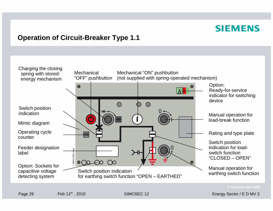
Block-Type Current Transformers and Voltage Transformers
4MA7 current transformer
� Designed as indoor block-type current transformer, 1-pole
4MR voltage transformer
� Designed as indoor voltage transformer, 1-pole or 2-pole (option)
Application
� For billing metering panels type M
� For bus riser panel type H
� For installation at the feeder

Page 34 Feb 11th , 2010 Energy Sector / E D MV 2SIMOSEC 12
© Siemens AG 2009
Low-Voltage Niche in Billing Metering Panel Type M

Page 35 Feb 11th , 2010 Energy Sector / E D MV 2SIMOSEC 12
© Siemens AG 2009
Low-Voltage Compartment
� Height: 350 mm550 mm (option)
� For installation on the panel
� For accommodation of protection, control, metering and measuring devices
� Usable mounting depth: 442 mm
Low-voltage compartment
Overall height: 350 mm (standard)
Page 36 Feb 11th , 2010 Energy Sector / E D MV 2SIMOSEC 12
© Siemens AG 2009
Classification According to IEC 62 271-200
Partition class: PM
Loss of service continuity category :
� LSC 2B (for switchgear panels without HV HRC fuses)
� LSC 2A (for switchgear panels with HV HRC fuses)
� Switchgear panels type M or type H are also an integral part of the busbar within a SIMOSEC 12 switchgear assembly. According to IEC 62 271-200 a category is not applied

Page 37 Feb 11th , 2010 Energy Sector / E D MV 2SIMOSEC 12
© Siemens AG 2009
Classification According to IEC 62 271-200
Accessibility of compartments:
� Busbar compartment: Tool-based
� Switching-device compartment : Non-accessible
� Low-voltage compartment: Tool-based
� Cable compartment without HV HRC fuses: Interlock-controlled
or tool-based
� Cable compartment with HV HRC fuses: Interlock-controlled
Page 38 Feb 11th , 2010 Energy Sector / E D MV 2SIMOSEC 12
© Siemens AG 2009
Compactness
Our solution3-pole primary enclosure
Combined disconnector and earthing switch,compact switch design
Phases arranged one behind the other
Integrated low-voltage nichefor accommodation of e.g. terminals, m.c.b.’s, pushbuttons and protection devices
Welded stainless-steel vessels
for switching devices, with insulating gas SF6
Your benefitMinimum space requirements,efficient use of existing rooms, reduced volume for new constructions,compact design reduces transport andinstallation costs to a minimum
No cable basement required
The modular, space saving designenables application in
- substations and customer transfer substations as well as distribution and switching substations used by power supply and public utilities
- public buildings like high-rise buildings, railway stations, hospitals
- industrial plants

Page 39 Feb 11th , 2010 Energy Sector / E D MV 2SIMOSEC 12
© Siemens AG 2009
Personal Safety
Your benefitTouching of live parts excluded,extremely high degree of protection of the primary part
Accidental opening of vessel excluded
Maloperation excluded
Verification of safe isolation from supplywithout opening the enclosure
Our solutionLSC2A or LS2B panels
All switching operations can be performed with closed panel front
Logical mechanical interlocks
Capacitive voltage detecting systemto verify safe isolation from supply
Feeder earthing possible with make-proof earthing switches
HV HRC fuses and cable sealing endsonly accessible when feeders are earthed

Page 40 Feb 11th , 2010 Energy Sector / E D MV 2SIMOSEC 12
© Siemens AG 2009
Operational Safety, Reliability
Our solutionHermetically welded switchgear vesselwith welded-in bushings for cable connection, busbar and operating mechanism
Operating mechanism components maintenance-freeoutside the switchgear vessel
Type and routine tests, quality management
NC production processes
Busbar in metal-clad busbar compartment
Current transformers as three-phase current transformers
Your benefitMTBF (2,625 years at the moment for SIMOSEC)
More than 600,000 switching-devicecomponents in world-wide operation foryears
Low susceptibility to faults in case of humidity and pollution
No dielectric and dynamic stress forcurrent transformers
No cross insulating of isolating distancesfrom phase to phase

Page 41 Feb 11th , 2010 Energy Sector / E D MV 2SIMOSEC 12
© Siemens AG 2009
Economy, Ecology
Our solutionCompact construction
Economic production
SF6 only used in hermetically sealed pressure system
100% SF6-recycling by means of special tools
Listing of all materials used
Your benefitMinimized owner expenses, high availability
Reduced transport costs
Minimum requirements regarding the building
Low volume
Reliable, calculable disposal

Page 42 Feb 11th , 2010 Energy Sector / E D MV 2SIMOSEC 12
© Siemens AG 2009
SIMOSEC 12, the air-insulated switchgear up to
12 kV, 25 kA, 630 A feeder, 1250 A busbar
Thanks for your attention.