SIMATIC DP/PA Link and Y Link Bus Couplings
182
Preface, Contents Product Overview 1 Description of Components 2 Installation 3 Wiring 4 Commissioning the DP/PA Coupler for Stand-Alone Operation 5 Commissioning the DP/PA Link 6 Commissioning the Y Link 7 Operation of the DP/PA Link and the Y Link 8 Diagnostics Using LEDs 9 Diagnostics Using the User Program 10 Appendices Fundamentals of PROFIBUS-PA A Technical Specifications B DP Slaves Connectable to a Y Link C Order Numbers and Accessories D Glossary, Index Edition 12/2002 A5E00193841-011 DP/PA Link and Y Link Bus Couplings Manual SIMATIC This manual has the order number: 6ES7157-0AA00-8BA0
Transcript of SIMATIC DP/PA Link and Y Link Bus Couplings

Preface, Contents
Product Overview1
Description of Components2
Installation3
Wiring4
Commissioning the DP/PACoupler for Stand-AloneOperation
5
Commissioning the DP/PA Link6
Commissioning the Y Link7
Operation of the DP/PA Link andthe Y Link
8
Diagnostics Using LEDs9
Diagnostics Using the UserProgram
10
Appendices
Fundamentals of PROFIBUS-PA A
Technical Specifications B
DP Slaves Connectable to aY Link
C
Order Numbers and AccessoriesD
Glossary, Index
Edition 12/2002A5E00193841-011
DP/PA Link and Y LinkBus Couplings
Manual
SIMATIC
This manual has the order number:6ES7157-0AA00-8BA0
Index-2DP/PA Link and Y Link Bus Couplings
A5E00193841-011
!Danger
indicates that death, severe personal injury or substantial property damage will result if proper precautionsare not taken.
!Warning
indicates that death, severe personal injury or substantial property damage can result if properprecautions are not taken.
!Caution
indicates that minor personal injury can result if proper precautions are not taken.
Caution
indicates that property damage can result if proper precautions are not taken.
Notice
draws your attention to particularly important information on the product, handling the product, or to aparticular part of the documentation.
Qualified PersonnelOnly qualified personnel should be allowed to install and work on this equipment. Qualified persons aredefined as persons who are authorized to commission, to ground and to tag circuits, equipment, andsystems in accordance with established safety practices and standards.
Correct UsageNote the following:
!Warning
This device and its components may only be used for the applications described in the catalog or thetechnical description, and only in connection with devices or components from other manufacturers whichhave been approved or recommended by Siemens.
This product can only function correctly and safely if it is transported, stored, set up, and installedcorrectly, and operated and maintained as recommended.
TrademarksSIMATIC, SIMATIC HMI and SIMATIC NET are registered trademarks of SIEMENS AG.
Third parties using for their own purposes any other names in this document which refer to trademarksmight infringe upon the rights of the trademark owners.
Safety GuidelinesThis manual contains notices intended to ensure personal safety, as well as to protect the products andconnected equipment against damage. These notices are highlighted by the symbols shown below andgraded according to severity by the following texts:
We have checked the contents of this manual for agreementwith the hardware and software described. Since deviationscannot be precluded entirely, we cannot guarantee fullagreement. However, the data in this manual are reviewedregularly and any necessary corrections included insubsequent editions. Suggestions for improvement arewelcomed.
Disclaim of LiabilityCopyright Siemens AG 1997-2002 All rights reserved
The reproduction, transmission or use of this document or itscontents is not permitted without express written authority.Offenders will be liable for damages. All rights, including rightscreated by patent grant or registration of a utility model ordesign, are reserved.
Siemens AGBereich Automation and DrivesGeschaeftsgebiet Industrial Automation SystemsPostfach 4848, D- 90327 Nuernberg
Siemens AG 2002Technical data subject to change.
Siemens Aktiengesellschaft A5E00193841011

iiiDP/PA Link and Y Link Bus Couplings A5E00193841-011
Preface
Purpose of the manual
This manual contains everything you need to know to configure, install, wire andcommission the DP/PA link and Y link couplers.
Required basic knowledge
The following basic knowledge is necessary to understand this manual:
General knowledge in the field of automation technology
Familiarity with the use of computers or PC-related equipment (e. g.programming devices) under the Windows 2000 or NT operating system
Skills in the use of STEP 7. These are imparted in the manual entitled”Programming with STEP 7 V5.2”.
Scope of this manual
This manual applies for the following products:
IM 157: 6ES7 157-0AA82-0XA0 (as of firmware version V4.0.0)
DP/PA coupler Ex [i]: 6ES7 157-0AD81-0XA0
DP/PA coupler: 6ES7 157-0AC80-0XA0
Y coupler: 6ES7 197-1LB00-0XA0
BM PS/IM bus module: 6ES7 195-7HA00-0XA0
BM IM/IM: 6ES7 195-7HD80-0XA0 bus module
BM DP/PA coupler bus module: 6ES7 195-7HF80-0XA0
BM Y coupler bus module: 6ES7 654-7HY00-0XA0
Complete package consisting of the above-mentioned components:6ES7 197-1LA01-0XA0
It describes the components valid at the time of the manual’s publication. Wereserve the right to enclose a product information document containing currentinformation with new components and new releases of components.

Preface
ivDP/PA Link and Y Link Bus Couplings
A5E00193841-011
Changes since the previous version
The following changes have been made since the previous version of this manual,DP/PA Bus Coupler Manual (order number 6ES7 157-0AA00-8xA0, release 4):
Integration of the description of the Y link coupler
New components:
– IM 157: 6ES7 157-0AA82-0XA0
– DP/PA coupler Ex [i]: 6ES7 157-0AD81-0XA0
– Y coupler: 6ES7 197-1LB00-0XA0
The IM 157 features the following new functions as of the firmware version citedabove:
DPV1 support with full diagnostics
Interrupt processing is now possible for non-redundant operation as well
System changes can be made during operation (also for non-redundantoperation)
Identification data are provided for the positive identification of the device in thesystem
Firmware update via PROFIBUS-DP (not for redundant operation)
The description of the parameter assignment and configuration frames is nolonger part of this manual. It can now be found on the Internet:
http://www.ad.siemens.de/simatic-cs
Configuration with STEP 7
The DP/PA link and Y link couplers can be configured with STEP 7 as of V5.2.
Approvals
The DP/PA link and Y link couplers comply with the following approvals:
Underwriters Laboratories, Inc.: UL 508(Industrial Control Equipment)
Canadian Standards Association: CSA C22.2 Number 142,(Process Control Equipment)
Factory Mutual Research: Approval Standard Class Number 3611
C tick mark
The DP/PA link and Y link couplers meet the requirements of the AS/NZS 2064standard (Australia and New Zealand).

Preface
vDP/PA Link and Y Link Bus Couplings A5E00193841-011
Standards
The DP/PA link and Y link couplers meet the requirements and criteria of theIEC 61784-1:2002 Ed1 CPF 3 PROFIBUS and PROFInet.
Additional information on the standards this equipment complies with and theissued approvals is found in Appendix B.
Position in the information landscape
In addition to this manual, you will also require the following manuals, dependingon the hardware you are using:
The manual of the DP master being used, especially the following information:
– Configuration and commissioning of a DP master system
– Description of the DP master
The manual entitled SIMATIC NET, PROFIBUS Networks (order no. 6GK1 970-5CA10-0xA0)
The installation manual entitled Automation System S7-300, Installation (order no. 6ES7 398-8AA03-8xA0)
The manual entitled Automation Systems S7-300, M7-300, ET 200M Ex I/OModules (order no. 6ES7 398-8RA00-8xA0), especially the information on thesubject of intrinsic safety and explosion protection.
Manual guide
This manual is subdivided into the following topics:
Product overview and description of components
Installation, wiring and commissioning
Operation and diagnostics
Appendices
Important terminology is explained in the glossary.
The index will help you rapidly find the text passages associated with specifickeywords.
Recycling and disposal
The described components can be recycled on account of their low-emissionmaterials. To recycle or dispose of your used equipment in anenvironmentally-compatible manner, turn to a disposal company certified forelectronics scrap.

Preface
viDP/PA Link and Y Link Bus Couplings
A5E00193841-011
Additional support
If you have any questions on the use of the product described in this manual thatare not answered here, please contact your Siemens partner at your localrepresentative or branch office.
http://www.ad.siemens.de/partner
If you require a device master file, it is available to you the Internet:
http://www.ad.siemens.de/csi_e/gsd
Training center
We offer courses that will help you ease your way into the field of automationtechnology. Please turn to your regional training center or to the central trainingcenter in D-90327 Nuremberg.
Telephone: +49 (911) 895-3200
Internet: http://www.sitrain.com
Preface
viiDP/PA Link and Y Link Bus Couplings A5E00193841-011
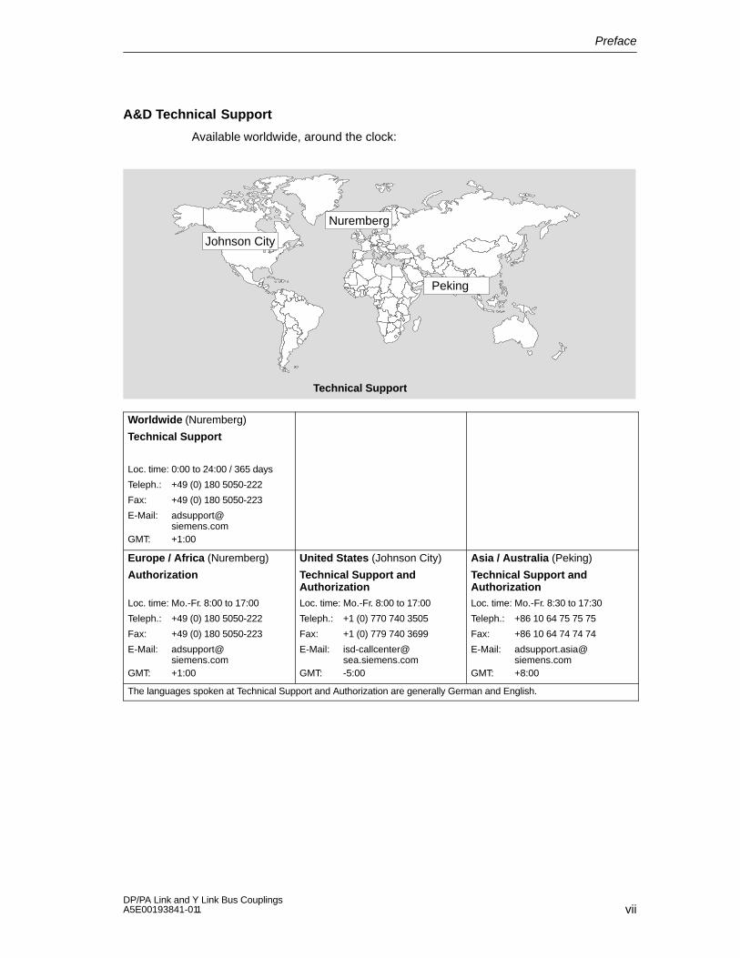
A&D Technical Support
Available worldwide, around the clock:
Johnson City
Nuremberg
Peking
Technical Support
Worldwide (Nuremberg)
Technical Support
Loc. time: 0:00 to 24:00 / 365 days
Teleph.: +49 (0) 180 5050-222
Fax: +49 (0) 180 5050-223
E-Mail: [email protected]
GMT: +1:00
Europe / Africa (Nuremberg)
Authorization
Loc. time: Mo.-Fr. 8:00 to 17:00
Teleph.: +49 (0) 180 5050-222
Fax: +49 (0) 180 5050-223
E-Mail: [email protected]
GMT: +1:00
United States (Johnson City)
Technical Support andAuthorizationLoc. time: Mo.-Fr. 8:00 to 17:00
Teleph.: +1 (0) 770 740 3505
Fax: +1 (0) 779 740 3699
E-Mail: [email protected]
GMT: -5:00
Asia / Australia (Peking)
Technical Support andAuthorizationLoc. time: Mo.-Fr. 8:30 to 17:30
Teleph.: +86 10 64 75 75 75
Fax: +86 10 64 74 74 74
E-Mail: [email protected]
GMT: +8:00
The languages spoken at Technical Support and Authorization are generally German and English.

Preface
viiiDP/PA Link and Y Link Bus Couplings
A5E00193841-011
Service & Support on the Internet
In addition to our documentation, we have also made our know-how available toyou online on the Internet.
http://www.siemens.com/automation/service&support
Here you will find the following:
The newsletter that keeps you up-to-date with the latest information regardingyour products.
The documents you require, which can be found using the Search function inService & Support.
A forum for the exchange of information between users and specialistsworldwide.
Your local representative for Automation & Drives, available on ourrepresentatives database.
Information on local service, repairs, spare parts. Still more information isavailable to you under ”Services”.
ixDP/PA Link and Y Link Bus Couplings A5E00193841-011
Contents
Preface
1 Product Overview
1.1 Bus couplings 1-1. . . . . . . . . . . . . . . . . . . . . . . . . . . . . . . . . . . . . . . . . . . . . . . . . . .
1.2 Integration in the automation landscape 1-2. . . . . . . . . . . . . . . . . . . . . . . . . . . . 1.2.1 What is a distributed I/O system? 1-2. . . . . . . . . . . . . . . . . . . . . . . . . . . . . . . . . . 1.2.2 DP/PA coupler 1-4. . . . . . . . . . . . . . . . . . . . . . . . . . . . . . . . . . . . . . . . . . . . . . . . . . 1.2.3 DP/PA link 1-5. . . . . . . . . . . . . . . . . . . . . . . . . . . . . . . . . . . . . . . . . . . . . . . . . . . . . . 1.2.4 Y link 1-6. . . . . . . . . . . . . . . . . . . . . . . . . . . . . . . . . . . . . . . . . . . . . . . . . . . . . . . . . .
2 Description of Components
2.1 DP/PA coupler 2-2. . . . . . . . . . . . . . . . . . . . . . . . . . . . . . . . . . . . . . . . . . . . . . . . . .
2.2 Y coupler 2-3. . . . . . . . . . . . . . . . . . . . . . . . . . . . . . . . . . . . . . . . . . . . . . . . . . . . . . .
2.3 IM 157 2-4. . . . . . . . . . . . . . . . . . . . . . . . . . . . . . . . . . . . . . . . . . . . . . . . . . . . . . . . .
2.4 DP/PA link 2-5. . . . . . . . . . . . . . . . . . . . . . . . . . . . . . . . . . . . . . . . . . . . . . . . . . . . . .
2.5 Y link 2-8. . . . . . . . . . . . . . . . . . . . . . . . . . . . . . . . . . . . . . . . . . . . . . . . . . . . . . . . . .
2.6 Modifications with respect to precursor modules 2-10. . . . . . . . . . . . . . . . . . . . .
2.7 Compatibility to precursor modules 2-10. . . . . . . . . . . . . . . . . . . . . . . . . . . . . . . .
3 Installation
3.1 Installation principles 3-1. . . . . . . . . . . . . . . . . . . . . . . . . . . . . . . . . . . . . . . . . . . . .
3.2 Installing the DP/PA coupler for stand-alone operation 3-3. . . . . . . . . . . . . . . .
3.3 Installing the DP/PA link for non-redundant operation 3-4. . . . . . . . . . . . . . . . .
3.4 Installing the DP/PA link for redundant operation 3-6. . . . . . . . . . . . . . . . . . . . .
3.5 Installing the Y link 3-9. . . . . . . . . . . . . . . . . . . . . . . . . . . . . . . . . . . . . . . . . . . . . .
4 Wiring
4.1 Electrical isolation and grounding 4-1. . . . . . . . . . . . . . . . . . . . . . . . . . . . . . . . . . 4.1.1 General rules and regulations for operation 4-2. . . . . . . . . . . . . . . . . . . . . . . . . 4.1.2 Operation with a grounded supply 4-4. . . . . . . . . . . . . . . . . . . . . . . . . . . . . . . . . 4.1.3 Operation with ungrounded reference potential 4-5. . . . . . . . . . . . . . . . . . . . . .
4.2 Connections 4-7. . . . . . . . . . . . . . . . . . . . . . . . . . . . . . . . . . . . . . . . . . . . . . . . . . . . 4.2.1 Wiring the DP/PA coupler for stand-alone operation 4-7. . . . . . . . . . . . . . . . . . 4.2.2 Wiring the DP/PA link for non-redundant operation 4-8. . . . . . . . . . . . . . . . . . . 4.2.3 Wiring the DP/PA link for redundant operation 4-9. . . . . . . . . . . . . . . . . . . . . . . 4.2.4 Wiring the Y link 4-10. . . . . . . . . . . . . . . . . . . . . . . . . . . . . . . . . . . . . . . . . . . . . . . . .
4.3 Connecting the power supply 4-11. . . . . . . . . . . . . . . . . . . . . . . . . . . . . . . . . . . . .
Contents
xDP/PA Link and Y Link Bus Couplings
A5E00193841-011
4.4 Connecting PROFIBUS-DP 4-12. . . . . . . . . . . . . . . . . . . . . . . . . . . . . . . . . . . . . . .
4.5 Connecting PROFIBUS-PA 4-12. . . . . . . . . . . . . . . . . . . . . . . . . . . . . . . . . . . . . . .
5 Commissioning the DP/PA Coupler for Stand-Alone Operation
6 Commissioning the DP/PA Link
6.1 Commissioning the DP/PA link 6-2. . . . . . . . . . . . . . . . . . . . . . . . . . . . . . . . . . . .
6.2 Configuration for S7 standard operation or redundant operation 6-3. . . . . . . . 6.2.1 Configuring the DP/PA link 6-3. . . . . . . . . . . . . . . . . . . . . . . . . . . . . . . . . . . . . . . . 6.2.2 Configuring the PROFIBUS-PA master system 6-5. . . . . . . . . . . . . . . . . . . . . .
6.3 Configuration for DP standard master operation 6-6. . . . . . . . . . . . . . . . . . . . . 6.3.1 Device master files 6-6. . . . . . . . . . . . . . . . . . . . . . . . . . . . . . . . . . . . . . . . . . . . . . 6.3.2 Configuring the DP/PA link 6-7. . . . . . . . . . . . . . . . . . . . . . . . . . . . . . . . . . . . . . . . 6.3.3 Configuring PROFIBUS-PA field devices 6-8. . . . . . . . . . . . . . . . . . . . . . . . . . .
6.4 Setting the PROFIBUS address of the IM 157 6-10. . . . . . . . . . . . . . . . . . . . . . .
7 Commissioning the Y Link
7.1 Commissioning the Y link 7-1. . . . . . . . . . . . . . . . . . . . . . . . . . . . . . . . . . . . . . . . .
7.2 Configuring the Y link 7-2. . . . . . . . . . . . . . . . . . . . . . . . . . . . . . . . . . . . . . . . . . . .
7.3 Configuring underlying DP slaves 7-4. . . . . . . . . . . . . . . . . . . . . . . . . . . . . . . . . .
8 Operation of the DP/PA Link and the Y Link
8.1 Start-up delay 8-1. . . . . . . . . . . . . . . . . . . . . . . . . . . . . . . . . . . . . . . . . . . . . . . . . . .
8.2 Start-up characteristics 8-2. . . . . . . . . . . . . . . . . . . . . . . . . . . . . . . . . . . . . . . . . . . 8.2.1 Start-up behavior of the DP/PA link in non-redundant operation 8-2. . . . . . . . 8.2.2 Start-up behavior in redundant operation 8-4. . . . . . . . . . . . . . . . . . . . . . . . . . .
8.3 Behavior following specific events in redundant operation 8-6. . . . . . . . . . . . .
8.4 Reading and writing records 8-7. . . . . . . . . . . . . . . . . . . . . . . . . . . . . . . . . . . . . .
8.5 Identification data 8-9. . . . . . . . . . . . . . . . . . . . . . . . . . . . . . . . . . . . . . . . . . . . . . .
8.6 Replacing faulty modules 8-11. . . . . . . . . . . . . . . . . . . . . . . . . . . . . . . . . . . . . . . . .
8.7 System changes during operation 8-11. . . . . . . . . . . . . . . . . . . . . . . . . . . . . . . . . 8.7.1 System changes in S7 standard operation 8-11. . . . . . . . . . . . . . . . . . . . . . . . . . 8.7.2 System changes in redundant operation 8-12. . . . . . . . . . . . . . . . . . . . . . . . . . . .
8.8 IM 157 firmware update 8-12. . . . . . . . . . . . . . . . . . . . . . . . . . . . . . . . . . . . . . . . . .
9 Diagnostics Using LEDs
9.1 LED displays of the IM 157 9-2. . . . . . . . . . . . . . . . . . . . . . . . . . . . . . . . . . . . . . .
9.2 LED displays of the DP/PA coupler 9-5. . . . . . . . . . . . . . . . . . . . . . . . . . . . . . . .
9.3 LED displays of the Y coupler 9-6. . . . . . . . . . . . . . . . . . . . . . . . . . . . . . . . . . . . .
10 Diagnostics Using the User Program
10.1 Structure of the slave diagnosis 10-2. . . . . . . . . . . . . . . . . . . . . . . . . . . . . . . . . . .
10.2 Structure of the diagnostic blocks 10-4. . . . . . . . . . . . . . . . . . . . . . . . . . . . . . . . . . 10.2.1 Standard diagnosis 10-4. . . . . . . . . . . . . . . . . . . . . . . . . . . . . . . . . . . . . . . . . . . . . . 10.2.2 Module diagnosis 10-6. . . . . . . . . . . . . . . . . . . . . . . . . . . . . . . . . . . . . . . . . . . . . . . .

Contents
xiDP/PA Link and Y Link Bus Couplings A5E00193841-011
10.2.3 Module status 10-8. . . . . . . . . . . . . . . . . . . . . . . . . . . . . . . . . . . . . . . . . . . . . . . . . . . 10.2.4 Status message 10-9. . . . . . . . . . . . . . . . . . . . . . . . . . . . . . . . . . . . . . . . . . . . . . . . . 10.2.5 H status 10-13. . . . . . . . . . . . . . . . . . . . . . . . . . . . . . . . . . . . . . . . . . . . . . . . . . . . . . . . 10.2.6 Interrupts 10-14. . . . . . . . . . . . . . . . . . . . . . . . . . . . . . . . . . . . . . . . . . . . . . . . . . . . . . .
10.3 Reading out the diagnosis from the underlying slaves 10-17. . . . . . . . . . . . . . . .
10.4 Example of a diagnosis in redundant operation 10-18. . . . . . . . . . . . . . . . . . . . . . 10.4.1 Task 10-18. . . . . . . . . . . . . . . . . . . . . . . . . . . . . . . . . . . . . . . . . . . . . . . . . . . . . . . . . . . 10.4.2 Solution with STEP 7 10-19. . . . . . . . . . . . . . . . . . . . . . . . . . . . . . . . . . . . . . . . . . . . 10.4.3 Evaluation of the diagnostic data 10-20. . . . . . . . . . . . . . . . . . . . . . . . . . . . . . . . . .
A Fundamentals of PROFIBUS-PA
A.1 Intrinsic safety A-2. . . . . . . . . . . . . . . . . . . . . . . . . . . . . . . . . . . . . . . . . . . . . . . . . .
A.2 Field device supply via PROFIBUS-PA A-3. . . . . . . . . . . . . . . . . . . . . . . . . . . . .
A.3 Extending PROFIBUS-PA with the DP/PA link coupler A-4. . . . . . . . . . . . . . . .
A.4 Partyline and star-type topology A-5. . . . . . . . . . . . . . . . . . . . . . . . . . . . . . . . . . .
B Technical Specifications
B.1 General technical specifications B-2. . . . . . . . . . . . . . . . . . . . . . . . . . . . . . . . . . . B.1.1 Standards and approvals B-2. . . . . . . . . . . . . . . . . . . . . . . . . . . . . . . . . . . . . . . . . B.1.2 Standards and approvals for the DP/PA coupler Ex [i] B-5. . . . . . . . . . . . . . . . B.1.3 Electromagnetic compatibility B-7. . . . . . . . . . . . . . . . . . . . . . . . . . . . . . . . . . . . . B.1.4 Transportation and storage conditions B-9. . . . . . . . . . . . . . . . . . . . . . . . . . . . . . B.1.5 Mechanical and climatic ambient conditions for operation B-9. . . . . . . . . . . . . B.1.6 Data on insulation tests, protection class and degree of protection B-12. . . . . B.1.7 Rated voltage B-13. . . . . . . . . . . . . . . . . . . . . . . . . . . . . . . . . . . . . . . . . . . . . . . . . . .
B.2 Use of the DP/PA link coupler in the Zone 2 hazardous area (in all official EU languages) B-13. . . . . . . . . . . . . . . . . . . . . . . . . . . . . . . . . . . . . .
B.3 Technical specifications of the IM 157 (6ES7 157-0AA82-0XA0) B-36. . . . . . .
B.4 Technical specifications of the DP/PA coupler Ex [i] (6ES7 157-0AD81-0XA0) B-37. . . . . . . . . . . . . . . . . . . . . . . . . . . . . . . . . . . . . . . . .
B.5 Technical specifications of the DP/PA coupler (6ES7 157-0AC80-0XA0) B-38. . . . . . . . . . . . . . . . . . . . . . . . . . . . . . . . . . . . . . . . .
B.6 Technical specifications of the Y coupler (6ES7 197-1LB00-0XA0) B-39. . . . .
C DP Slaves Connectable to a Y Link
D Order Numbers and Accessories
D.1 Coupler components D-1. . . . . . . . . . . . . . . . . . . . . . . . . . . . . . . . . . . . . . . . . . . . .
D.2 Accessories for PROFIBUS-DP D-2. . . . . . . . . . . . . . . . . . . . . . . . . . . . . . . . . . .
D.3 PROFIBUS-PA accessories D-2. . . . . . . . . . . . . . . . . . . . . . . . . . . . . . . . . . . . . .
Glossary
Index
Contents
xiiDP/PA Link and Y Link Bus Couplings
A5E00193841-011
Figures
1-1 Integration of the DP/PA coupler in the system landscape 1-4. . . . . . . . . . . . . 1-2 Integration of the DP/PA link in the system landscape 1-5. . . . . . . . . . . . . . . . 1-3 Integration of the Y link in the system landscape 1-6. . . . . . . . . . . . . . . . . . . . . 3-1 Typical configuration of the DP/PA link for non-redundant operation 3-4. . . . 3-2 Typical configuration of the DP/PA link for redundancy operation 3-6. . . . . . . 3-3 Typical configuration of the Y link 3-9. . . . . . . . . . . . . . . . . . . . . . . . . . . . . . . . . . 4-1 Braided screen of the PROFIBUS cable on the grounded shield bus 4-3. . . 4-2 Configuration with a grounded supply 4-5. . . . . . . . . . . . . . . . . . . . . . . . . . . . . . 4-3 Configuration with ungrounded reference potential 4-6. . . . . . . . . . . . . . . . . . . 4-4 DP/PA coupler connections for stand-alone operation 4-7. . . . . . . . . . . . . . . . 4-5 DP/PA link connections for non-redundant operation 4-8. . . . . . . . . . . . . . . . . 4-6 DP/PA link connections for redundancy operation 4-9. . . . . . . . . . . . . . . . . . . . 4-7 Y link connections 4-10. . . . . . . . . . . . . . . . . . . . . . . . . . . . . . . . . . . . . . . . . . . . . . . 4-8 Power supply for IM 157 4-11. . . . . . . . . . . . . . . . . . . . . . . . . . . . . . . . . . . . . . . . . 4-9 PROFIBUS-PA connection 4-13. . . . . . . . . . . . . . . . . . . . . . . . . . . . . . . . . . . . . . . 4-10 PA bus terminating switch 4-14. . . . . . . . . . . . . . . . . . . . . . . . . . . . . . . . . . . . . . . . 4-11 Length of insulation stripped 4-14. . . . . . . . . . . . . . . . . . . . . . . . . . . . . . . . . . . . . . 6-1 HW Config: DP/PA link in hardware catalog 6-4. . . . . . . . . . . . . . . . . . . . . . . . . 6-2 HW Config: Minimum configuration of an S7-400H with a DP/PA link 6-4. . . 6-3 Example of a configuration with COM PROFIBUS 6-9. . . . . . . . . . . . . . . . . . . 6-4 Entering the PROFIBUS address 6-10. . . . . . . . . . . . . . . . . . . . . . . . . . . . . . . . . . 6-5 Example for setting the PROFIBUS address 6-11. . . . . . . . . . . . . . . . . . . . . . . . 7-1 HW Config: Y link in hardware catalog 7-3. . . . . . . . . . . . . . . . . . . . . . . . . . . . . 7-2 HW Config: Minimum configuration of an S7-400H with a Y link 7-3. . . . . . . . 8-1 Start-up behavior of the IM 157 after power is switched on 8-3. . . . . . . . . . . . 8-2 Start-up behavior of the two IM 157 modules in redundant operation 8-5. . . 8-3 Update directly via PROFIBUS-DP (programming device/PC is
connected directly to the IM 157) 8-14. . . . . . . . . . . . . . . . . . . . . . . . . . . . . . . . . . 8-4 Update via MPI to the CPU and then via PROFIBUS-DP
(programming device/PC is connected to the CPU) 8-14. . . . . . . . . . . . . . . . . . 10-1 Structure of the standard diagnosis 10-4. . . . . . . . . . . . . . . . . . . . . . . . . . . . . . . . 10-2 Example of a slot assignment 10-6. . . . . . . . . . . . . . . . . . . . . . . . . . . . . . . . . . . . . 10-3 Structure of the module diagnosis 10-7. . . . . . . . . . . . . . . . . . . . . . . . . . . . . . . . . 10-4 Structure of the module status 10-9. . . . . . . . . . . . . . . . . . . . . . . . . . . . . . . . . . . . 10-5 Structure of the status message 10-10. . . . . . . . . . . . . . . . . . . . . . . . . . . . . . . . . . . 10-6 Structure of the status message, continued 10-11. . . . . . . . . . . . . . . . . . . . . . . . . 10-7 Structure of the H status of the IM 157 in redundant operation
on the S7-400H 10-13. . . . . . . . . . . . . . . . . . . . . . . . . . . . . . . . . . . . . . . . . . . . . . . . . 10-8 Structure of the interrupt section on the redundant S7 master
that is not capable of DPV1 10-14. . . . . . . . . . . . . . . . . . . . . . . . . . . . . . . . . . . . . . . 10-9 Structure of the interrupt header on the DPV1-capable DP master 10-15. . . . . 10-10 Structure of the additional interrupt information for the
insertion/removal interrupt 10-16. . . . . . . . . . . . . . . . . . . . . . . . . . . . . . . . . . . . . . . . A-1 Field device supply A-3. . . . . . . . . . . . . . . . . . . . . . . . . . . . . . . . . . . . . . . . . . . . . . A-2 Extension of PROFIBUS-PA with a DP/PA link or DP/PA couplers A-4. . . . . A-3 Partyline and star-type topology A-5. . . . . . . . . . . . . . . . . . . . . . . . . . . . . . . . . . . C-1 Configuration example (excerpt from HW Config) C-4. . . . . . . . . . . . . . . . . . . .

Contents
xiiiDP/PA Link and Y Link Bus Couplings A5E00193841-011
Tables
8-1 Configured start-up characteristics 8-2. . . . . . . . . . . . . . . . . . . . . . . . . . . . . . . . 8-2 Behavior following specific events in redundant operation 8-6. . . . . . . . . . . . 8-3 Methods for reading and writing records 8-7. . . . . . . . . . . . . . . . . . . . . . . . . . . 8-4 Call parameters for SFC 58 ”WR_REC” and SFC 59 ”RD_REC” 8-8. . . . . . 8-5 Error information of the IM 157 8-8. . . . . . . . . . . . . . . . . . . . . . . . . . . . . . . . . . . 8-6 Identification data 8-9. . . . . . . . . . . . . . . . . . . . . . . . . . . . . . . . . . . . . . . . . . . . . . . 9-1 Status and error messages of the IM 157 9-2. . . . . . . . . . . . . . . . . . . . . . . . . . . 9-2 Status and error messages of the DP/PA coupler 9-5. . . . . . . . . . . . . . . . . . . . 9-3 Status messages of the Y coupler 9-6. . . . . . . . . . . . . . . . . . . . . . . . . . . . . . . . . 10-1 Length and start addresses of the diagnostic blocks in S7
standard operation and in redundant operation 10-2. . . . . . . . . . . . . . . . . . . . . . 10-2 Length and start addresses of the diagnostic blocks in DP
standard master operation 10-3. . . . . . . . . . . . . . . . . . . . . . . . . . . . . . . . . . . . . . . 10-3 Structure of station status 1 10-4. . . . . . . . . . . . . . . . . . . . . . . . . . . . . . . . . . . . . . 10-4 Structure of station status 2 10-5. . . . . . . . . . . . . . . . . . . . . . . . . . . . . . . . . . . . . . . 10-5 Structure of station status 3 10-5. . . . . . . . . . . . . . . . . . . . . . . . . . . . . . . . . . . . . . . 10-6 Structure of the device identifier 10-6. . . . . . . . . . . . . . . . . . . . . . . . . . . . . . . . . . . 10-7 Meaning of byte x+36 in the status message 10-12. . . . . . . . . . . . . . . . . . . . . . . 10-8 Interrupt m type (byte x+1 in interrupt section) 10-15. . . . . . . . . . . . . . . . . . . . . . 10-9 Call parameters for SFC 59 ”RD_REC” 10-17. . . . . . . . . . . . . . . . . . . . . . . . . . . . 10-10 Call of the SFC 13 (DPNRM_DG) in the OB 1 10-19. . . . . . . . . . . . . . . . . . . . . . A-1 Spur line length for the DP/PA coupler A-6. . . . . . . . . . . . . . . . . . . . . . . . . . . . . B-1 Use in industrial enrivonments B-4. . . . . . . . . . . . . . . . . . . . . . . . . . . . . . . . . . . . B-2 Pulse-type interference B-7. . . . . . . . . . . . . . . . . . . . . . . . . . . . . . . . . . . . . . . . . . . B-3 Sinusoidal interference B-8. . . . . . . . . . . . . . . . . . . . . . . . . . . . . . . . . . . . . . . . . . . B-4 Transportation and storage conditions B-9. . . . . . . . . . . . . . . . . . . . . . . . . . . . . . B-5 Mechanical ambient conditions B-10. . . . . . . . . . . . . . . . . . . . . . . . . . . . . . . . . . . . B-6 Test for mechanical ambient conditions B-11. . . . . . . . . . . . . . . . . . . . . . . . . . . . . B-7 Climatic ambient conditions B-11. . . . . . . . . . . . . . . . . . . . . . . . . . . . . . . . . . . . . . . B-8 Test voltages B-12. . . . . . . . . . . . . . . . . . . . . . . . . . . . . . . . . . . . . . . . . . . . . . . . . . . C-1 Examples of directly configurable DP slaves C-1. . . . . . . . . . . . . . . . . . . . . . . . C-2 Examples of usable DP slaves C-2. . . . . . . . . . . . . . . . . . . . . . . . . . . . . . . . . . . . C-3 CPUs that can be used as I slaves with various I/O ranges C-3. . . . . . . . . . . D-1 Order numbers for the coupler components D-1. . . . . . . . . . . . . . . . . . . . . . . . D-2 Order numbers for the configuration accessories D-1. . . . . . . . . . . . . . . . . . . . D-3 Order numbers for PROFIBUS-DP accessories D-2. . . . . . . . . . . . . . . . . . . . . D-4 Order numbers for PROFIBUS-PA accessories D-2. . . . . . . . . . . . . . . . . . . . .

Contents
xivDP/PA Link and Y Link Bus Couplings
A5E00193841-011

1-1DP/PA Link and Y Link Bus Couplings A5E00193841-011
Product Overview
Overview of contents
This section describes which components are included under bus couplings andhow the bus couplings are integrated in the Siemens automation landscape.
Section Topic Page
1.1 Bus couplings 1-1
1.2 Integration in the automation landscape 1-2
1.1 Bus couplings
DP/PA coupler
The DP/PA coupler is the physical link between the PROFIBUS-DP andPROFIBUS-PA. In stand-alone operation, it provides a simple means ofcommunicating with PA field devices via PROFIBUS-DP. This does not require anyadditional components.
The DP/PA coupler is also employed in the DP/PA link for more demandingcoupling tasks (see below).
In addition to the “normal” version, the DP/PA coupler is also available in an Ex [i]version for connecting PA field devices in potentially explosive environments.
DP/PA link
The DP/PA link consists of one or two IM 157 interface modules and one to fiveDP/PA couplers that are interconnected either via passive bus connectors or viabus modules, as required.
The DP/PA link provides a gateway from a PROFIBUS-DP master system toPROFIBUS-PA. By means of the IM 157, the bus systems are decoupled bothphysically (electrically) and with respect to the protocol and time.
By employing two IM 157 interface modules, the underlying PROFIBUS-PA mastersystem as a whole can be connected as a switched I/O system to a redundant DPmaster system of an S7-400H. For this purpose, the structure is always beconfigured with bus modules.
1

Product Overview
1-2DP/PA Link and Y Link Bus Couplings
A5E00193841-011
Y link
The Y link consists of two IM 157 interface modules and a Y coupler that areinterconnected via bus modules.
The Y link provides a gateway from the redundant DP master system of anS7-400H to a non-redundant DP master system. This permits devices with onlyone PROFIBUS-DP interface to be connected to an S7-400H as a switched I/Osystem.
1.2 Integration in the automation landscape
1.2.1 What is a distributed I/O system?
Distributed I/O devices – area of application
When a system is set up, the inputs and outputs to and from the process are oftenlocated centrally in the automation system.
If the inputs and outputs are located at a considerable distance from theautomation system, this may lead to long and complex cable runs andelectromagnetic interference may impair system reliability.
A distributed I/O is the ideal solution for such systems:
The PROFIBUS-DP master is located centrally.
The I/O devices (inputs and outputs) operate locally on a distributed basis.
The high-performance PROFIBUS-DP bus system with its high transmissionrates ensures that the controller CPU and I/O devices communicate smoothly.
What is PROFIBUS-DP?
PROFIBUS-DP is an open bus system according to IEC 61784-1:2002 Ed1 CP 3/1with the “DP” transmission protocol (DP being the German abbreviation fordistributed I/O).
Physically, PROFIBUS-DP is either an electrical network based on a shieldedtwo-wire line or an optical network based on a fiber optic cable.
The “DP” transmission protocol allows very rapid, cyclic exchange of data betweenthe controller CPU and the distributed I/O devices.

Product Overview
1-3DP/PA Link and Y Link Bus Couplings A5E00193841-011
What is PROFIBUS-PA?
PROFIBUS-PA is the communication-compatible enhancement of PROFIBUS-DPwith transmission technology suitable for applications in potentially explosiveareas. The transmission system of PROFIBUS-PA meets the internationalstandard IEC 61784-1:2002 Ed1 CP 3/2.
With the PROFIBUS-PA bus system, the measuring transducer and actuators inthe potentially explosive area can communicate over long distances with theprogrammable logic controller. With PROFIBUS-PA, the field devices can be fedsimultaneously via the data line.
The following components are available for the transmission transition fromPROFIBUS-DP (IEC 61784-1:2002 Ed1 CP 3/1) to PROFIBUS-PA(IEC 61784-1:2002 Ed1 CP 3/2):
DP/PA coupler for stand-alone operation
DP/PA link
Product Overview
1-4DP/PA Link and Y Link Bus Couplings
A5E00193841-011
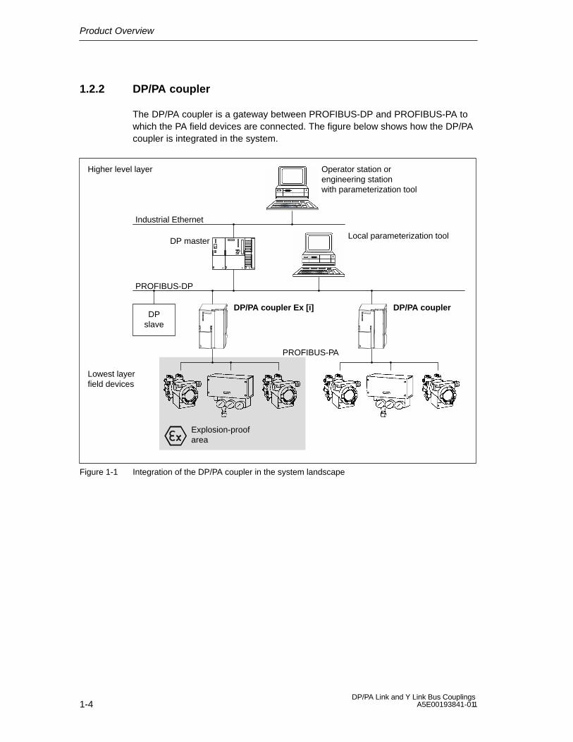
1.2.2 DP/PA coupler
The DP/PA coupler is a gateway between PROFIBUS-DP and PROFIBUS-PA towhich the PA field devices are connected. The figure below shows how the DP/PAcoupler is integrated in the system.
DP master
Higher level layer
PROFIBUS-DP
PROFIBUS-PA
DPslave
Lowest layerfield devices
Explosion-proofarea
DP/PA coupler Ex [i]
Operator station or engineering station with parameterization tool
Industrial Ethernet
Local parameterization tool
DP/PA coupler
Figure 1-1 Integration of the DP/PA coupler in the system landscape

Product Overview
1-5DP/PA Link and Y Link Bus Couplings A5E00193841-011
1.2.3 DP/PA link
To higher level systems, the DP/PA link is a DP slave (to the automation device)and to underlying systems it is a PA master. The figure below shows how theDP/PA link is integrated in the system.
DP master
Higher level layer
PROFIBUS-DP
DPslave
Underlying layerfield devices
Operator station or engineering station with parameterization tool
Industrial Ethernet
Local parameterization tool
IM 157 DP/PA coupler1 2 3 4 5
PROFIBUS-PA
PROFIBUS-PA field devices
DP/PA link
Figure 1-2 Integration of the DP/PA link in the system landscape

Product Overview
1-6DP/PA Link and Y Link Bus Couplings
A5E00193841-011
1.2.4 Y link
To higher level systems, the Y link is a switched DP slave (to the automationdevice) and to underlying systems it is a DP master. The figure below shows howthe Y link is integrated in the system.
S7-400H
Higher level layer
RedundantDP master system
RedundantDP slave
Distributed I/O devices
Operator station or engineering station with parameterization tool
Industrial Ethernet
Local parameterization tool
IM 157
Y link
Y coupler
Underlying DP master system
ET 200S ET 200X ET 200L Drive Other fielddevices
Figure 1-3 Integration of the Y link in the system landscape

2-1DP/PA Link and Y Link Bus Couplings A5E00193841-011
Description of Components
Overview of contents
This section briefly describes the individual modules and the DP/PA link and Y linkbus couplings that are assembled from the modules. In addition, a comparison isdrawn to the precursor modules.
Section Topic Page
2.1 DP/PA coupler 2-2
2.2 Y coupler 2-3
2.3 IM 157 2-4
2.4 DP/PA link 2-5
2.5 Y link 2-8
2.6 Modifications with respect to precursor modules 2-10
2.7 Compatibility to precursor modules 2-10
2

Description of Components
2-2DP/PA Link and Y Link Bus Couplings
A5E00193841-011
2.1 DP/PA coupler
The DP/PA coupler is intended for the following applications:
Stand-alone operation without additional components
Operation in the DP/PA link on a simple DP master system or on an S7-400H
Features
The DP/PA coupler has the following features:
Isolation between PROFIBUS-DP and PROFIBUS-PA
Implementation of the physical transmission system between RS 485 and thesynchronous physical bus level according to IEC 61784-1:2002 Ed1 CP 3/2
Diagnosis by means of LEDs
Transmission rate to PROFIBUS-DP of 45.45 kBaud
Transmission rate to PROFIBUS-PA of 31.25 kBaud
Integrated supply unit for PROFIBUS-PA
Integrated bus termination for PROFIBUS-PA
Extended range of environmental conditions
Special features of the DP/PA coupler Ex [i]
Version Ex [i] (6ES7 157-0AD81-0XA0) of the DP/PA coupler has the followingadditional features:
Suitable equipment for potentially explosive areas, zone 0, 1 and 2
Intrinsic safety for the underlying PROFIBUS-PA
Integrated intrinsically safe supply unit for PROFIBUS-PA interface andintegrated barrier
Configuration
The DP/PA coupler can be used as a stand-alone device in all DP masters thatsupport 45.45 kBaud.
The DP/PA coupler does not have to be configured. You only have to set thetransmission rate of 45.45 kBaud for the corresponding DP master system andconfigure and parameterize the PA field devices.
Note
If you use the IM 157 together with the DP/PA couplers as the DP/PA link, thePROFIBUS-DP connections on the DP/PA couplers are not required. The IM 157and the DP/PA couplers are connected via the S7 backplane bus.
Description of Components
2-3DP/PA Link and Y Link Bus Couplings A5E00193841-011
2.2 Y coupler
The Y coupler is only intended for operation in the Y link for use on an S7-400H.
The Y coupler cannot be operated without an IM 157.
Features
Connection of DP standard slaves
Transmission rate of 45.45 kBaud to 12 MBaud
Isolation between IM 157 and the underlying PROFIBUS-DP
The power supply of the Y coupler is provided via the backplane bus.
Configuration
The Y coupler is a component of the Y link and is not configured separately.
Description of Components
2-4DP/PA Link and Y Link Bus Couplings
A5E00193841-011
2.3 IM 157
As an interface module, the IM 157 is intended for the following applications:
Operation in the DP/PA link on a non-redundant DP master system or on anS7-400H
Operation in the Y link on an S7-400H
Features
All transmission rates from 9.6 kBaud to 12 MBaud for the higher-level DPmaster system
Diagnosis by means of LEDs and the user program
Bumpless switchover of active channel when in redundancy mode on theS7-400H
Support of system changes during operation both in the S7 standard mode andin the redundancy mode.
Can be operated as a DPV0 or DPV1 slave depending on the higher level DPmaster.

Description of Components
2-5DP/PA Link and Y Link Bus Couplings A5E00193841-011
2.4 DP/PA link
The DP/PA link is intended for the following applications:
S7 standard mode on the S7-300 or S7-400
Redundancy mode on the S7-400H
DP standard master mode
Some of the following details apply to both the S7 standard mode and to the DPnormal master mode. In these cases, the term “non-redundant operation” is used.
Operating principle
On the higher level DP master system, the DP/PA link is a DP slave and actsas a proxy for the nodes connected to the underlying bus system (PA fielddevices).
The DP/PA link forms an independent underlying bus system that is decoupledfrom the higher level DP master system with respect to communication.
The use of several DP/PA couplers increases the current carrying capacity ofthe PA master system.
Together with the connected PA field devices, the DP/PA couplers of a DP/PAlink form a single common bus system.
Configuration options
DP/PA links can be used to extend a DP master system as follows:
The number of DP/PA links on a DP master system is only limited by themaximum number of bus nodes of 126.
Up to five DP/PA couplers can be operated in each DP/PA link. Y couplerscannot be operated in the DP/PA link.
The number of nodes in each PA master system is limited to 64. The sum ofslots (see Section 10.2.2) is limited to (236 – number of PA slaves) in eachcase.
The configuration frame and the user data frame of the DP/PA link are bothderived from the frame contents of the underlying PA field devices.
The maximum length of the frames for configuration data, parameterassignment data, diagnostics data and I/O data is 244 bytes in each case.
Configuration
The DP/PA link can be configured with STEP 7 as of V5.2.

Description of Components
2-6DP/PA Link and Y Link Bus Couplings
A5E00193841-011
Parameter assignment for the PA field devices
With the aid of a suitable tool such as SIMATIC PDM, the parameters for the PAfield devices can be assigned on a programming device/PC that is connected tothe higher level PROFIBUS-DP. For more information, please refer to thedocumentation of your parameterization tool.
User data of the DP/PA link
The DP user data frame of the DP/PA link is dependent on the number ofconfigured PA field devices. It consists of the data blocks of the configured PA fielddevices arranged one next to the other. The data blocks are sorted in ascendingorder by PA address.
According to the PROFIBUS-PA Profile for Process Control Devices, GeneralRequirements, each process variable is accompanied by a status byte thatcontains information on the status of the process variable.
In the event of the failure of a PA field device, the associated input data and statusbyte in the user data frame of the DP/PA link are reset first. The correspondinginformation is then entered in the diagnostic frame.
When the PA field device is restored, the corresponding information is entered intothe diagnostic frame. At almost the same time, the valid input data of the PA fielddevice in the user data frame of the DP/PA link become available again. The statusbyte indicates that the data is valid.
Note
To obtain the status of the PA field devices as quickly as possible, it is advisable toregularly evaluate the status byte in the user program.

Description of Components
2-7DP/PA Link and Y Link Bus Couplings A5E00193841-011
Switchover time on PROFIBUS-PA in redundancy mode
In the case of a master-standby switchover or failure of the active IM 157, the PAfield devices are processed via the standby IM 157.
The switchover is bumpless, i.e. the statuses of the inputs/outputs are retainedduring the switchover.
The switchover time is defined as the time between activation of the standby IMand the availability of new input data.
Condition/prerequisite Switchover time
Switchover time given an unchanged Typ.: 70 ms + number of PA field devices x 51 msPA configuration
Max.: 820 ms + number of PA field devices x 50 ms
Switchover time after configuration Typ.: 80 ms + number of PA field devices* x 67 mschanges during operation
Max.: 800 ms + number of PA field devices* x 130 ms
* With unchanged PA field device addresses
Communication links from the programming device/PC to the PA field devices
Up to 10 communication links to PA field devices can be set up simultaneouslyfrom a programming device/PC via the DP/PA link.
In the redundancy mode, all communication links from the programming device/PCto the PA field devices remain intact when the active channel is switched over fromone IM 157 to another.

Description of Components
2-8DP/PA Link and Y Link Bus Couplings
A5E00193841-011
2.5 Y link
The Y link is only intended for use in the redundancy mode on S7-400H.
Operating principle
On the higher level DP master system, the Y link is a DP slave and acts as aproxy for the nodes connected to the underlying bus system (DP slaves).
The Y link forms an independent underlying bus system that is decoupled fromthe higher level DP master system with respect to communication.
Configuration options and limitations
Y links can be used to extend a redundant DP master system as follows:
The number of Y links on a S7-400H is only limited by the maximum number ofbus nodes of 126.
Only one Y coupler can be operated per Y link. DP/PA couplers cannot beoperated in the Y link.
The number of nodes in each underlying DP master system is limited to 64. Thesum of slots (see Section 10.2.2) is limited to (236 – number of PA slaves) ineach case.
The configuration frame and the user data frame of the Y link are both derivedfrom the frame contents of the underlying slaves.
The maximum length of the frames for configuration data, parameterizatondata, diagnostics data and I/O data is 244 bytes in each case.
It is not permissible to cascade Y links.
A direct exchange of data and synchronicity is not possible in the underlying DPmaster system.
Configuration
The Y link can be configured with STEP 7 as of V5.2.
For the calculation of bus parameters by STEP 7, the nodes connected to theunderlying DP master system and the Y link itself are included in the calculation.
Slaves on the underlying DP master system are only operated in the DPV1 mode ifthey are suitable for a bumpless switchover when a system change takes placeduring operation.
STEP 7 can identify a slave’s suitability by an entry in its device master file:
PrmCmd_supp=1
If this entry is not present, the slave is operated in DPV0 mode.

Description of Components
2-9DP/PA Link and Y Link Bus Couplings A5E00193841-011
Parameter assignment for the DP slave
The parameters for the DP slave in the underlying DP master system are assignedon the S7-400H via the Y link.
User data of the Y link
The DP user data frame of the Y link is dependent on the number of configured PAslaves. It consists of the data blocks of the configured DP slaves arranged onenext to the other. The data blocks are sorted in ascending order by DP address.
In the event of the failure of a DP slave, the associated input data in the user dataframe of the DP/PA link are reset first. The corresponding information is thenentered in the diagnostic frame.
When the DP slave is restored, the corresponding information is entered into thediagnostic frame. At almost the same time, the valid input data of the DP slave inthe user data frame of the Y link become available again.
Diagnostics data of the DP slaves
The processing of the diagnostic frames by DP slaves depends on whether the IM157 is operated as a DPV0 slave or as a DPV1 slave. For details, see Chapter 10.
In STEP 7, the diagnostic frames of the underlying DP slaves can be displayed inthe online view of the HW Config.
Communication links from the programming device/PC to the DP slaves
Up to 10 communication links to DP slaves can be set up simultaneously from aprogramming device/PC via the Y link.
Communication links can only be passed from the S7-400H to the underlying DPmaster system.
All communication links from the programming device/PC to the DP slaves remainintact when the active channel is switched over from one IM 157 to another.

Description of Components
2-10DP/PA Link and Y Link Bus Couplings
A5E00193841-011
2.6 Modifications with respect to precursor modules
IM 157
DPV1 support with full diagnostics
Interrupt processing is now possible for non-redundant operation as well
System changes are possible during operation (also for non-redundantoperation)
Identification data are provided for the positive identification of the device in thesystem
Firmware update via PROFIBUS-DP (not for redundant operation)
DP/PA coupler Ex [i]
Approved for potentially explosive areas in accordance with FM 3610 forCl.I, Div.1
Approved for installation in the potentially explosive area Zone 2
Y coupler
Integrated RS 485 repeater
2.7 Compatibility to precursor modules
Compatibility of the IM 157
The IM 157 with order number -0AA82- can be used as a spare part for allprecursor modules. In this case, the configuration can also be performed with anolder version of STEP 7. The information provided in the documentation of thefailed IM 157 apply.
Compatibility of the Y coupler
Y coupler 6ES7 197-1LB00-0XA0 cannot be used as a spare part for Y coupler6ES7 654-0YK00-0AB0.
Compatibility of the bus modules
Bus module BM IM/IM 6ES7 195-7HD80-0XA0 can only be used in conjunctionwith 6ES7 157-0AA82-0XA0 and cannot be used as a spare part for6ES7 195-7HE80-0XA0.
3-1DP/PA Link and Y Link Bus Couplings A5E00193841-011
Installation
Overview of contents
Section Topic Page
3.1 Installation principles 3-1
3.2 Installing the DP/PA coupler for stand-alone operation 3-3
3.3 Installing the DP/PA link for non-redundant operation 3-4
3.4 Installing the DP/PA link for redundant operation 3-6
3.5 Installing the Y link 3-9
3.1 Installation principles
Installation orientation
The IM 157, DP/PA coupler and Y coupler modules can be installed eithervertically or horizontally.
Open equipment
The IM 157, DP/PA coupler and Y coupler modules are open equipment. Thismeans they may only be installed in housings, cabinets or electrical operatingareas and must only be accessible by key or special tool. Only trained orauthorized personnel should have access to the housings, cabinets or electricaloperating areas.
Mounting system
The IM 157, DP/PA coupler and Y coupler modules are installed on rails for the S7mounting system. A clearance of at least 40 mm both above and below the modulemust be maintained for unhindered installation.
For more information on installing S7 modules, refer to the S7-300 ProgrammableController, Installation manual.
3

Installation
3-2DP/PA Link and Y Link Bus Couplings
A5E00193841-011
Installation location
The DP/PA coupler Ex [i] or the DP/PA link with DP/PA couplers Ex [i] can beoperated in potentially explosive areas classified as Zone 2 if they are installed in asuitable housing. The bus cable for PROFIBUS-PA may be extended out of thepotentially explosive area into Zone 0.
Housing for Zone 2
The DP/PA coupler Ex [i] or the DP/PA link with DP/PA couplers Ex [i] must bemounted in a housing with the IP 54 degree of protection. The housing must beaccompanied by a manufacturer’s declaration for Zone 2 (in accordance withEN 50021).
Use the following cable fittings:
Power supply and PROFIBUS-DP Ex i: Cable fitting with manufacturer’sdeclaration for Zone 2
PROFIBUS-PA Ex i: Type of protection EEx i
!Danger
Under certain circumstances, ignitable sparks or inadmissible surfacetemperatures may occur.
Never install the equipment under explosive conditions!
Installation
3-3DP/PA Link and Y Link Bus Couplings A5E00193841-011
3.2 Installing the DP/PA coupler for stand-alone operation
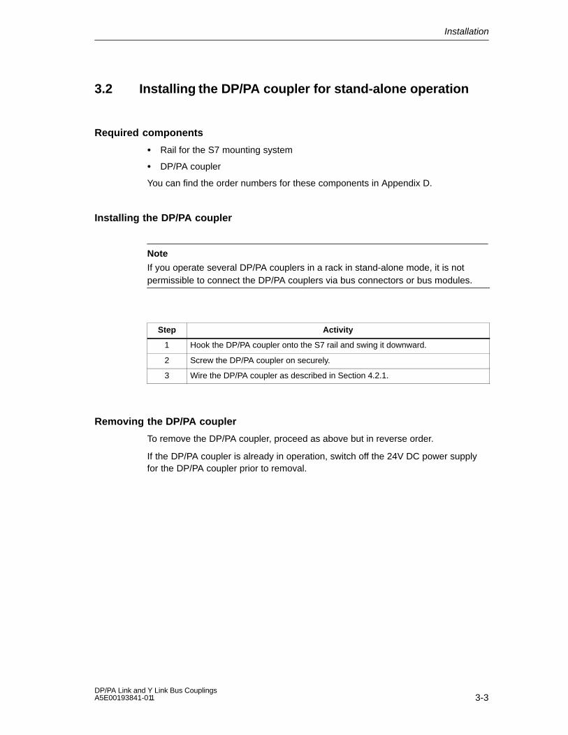
Required components
Rail for the S7 mounting system
DP/PA coupler
You can find the order numbers for these components in Appendix D.
Installing the DP/PA coupler
Note
If you operate several DP/PA couplers in a rack in stand-alone mode, it is notpermissible to connect the DP/PA couplers via bus connectors or bus modules.
Step Activity
1 Hook the DP/PA coupler onto the S7 rail and swing it downward.
2 Screw the DP/PA coupler on securely.
3 Wire the DP/PA coupler as described in Section 4.2.1.
Removing the DP/PA coupler
To remove the DP/PA coupler, proceed as above but in reverse order.
If the DP/PA coupler is already in operation, switch off the 24V DC power supplyfor the DP/PA coupler prior to removal.

Installation
3-4DP/PA Link and Y Link Bus Couplings
A5E00193841-011
3.3 Installing the DP/PA link for non-redundant operation
Required components
Rail for the S7 mounting system
IM 157
1 to 5 DP/PA couplers
One bus connector per DP/PA coupler (included)
Options for module exchange during operation:
– BM PS/IM or BM IM/IM bus module
– BM DP/PA coupler bus modules
You can find the order numbers for these components in Appendix D.
Typical configuration of the DP/PA link
The figure below shows the typical configuration of the DP/PA link with two DP/PAcouplers. The front doors are open.
PS 307 IM 157 DP/PA coupler
Bus connector(not visible)
Rail
DP/PA coupler
Bus connector(not visible)
Figure 3-1 Typical configuration of the DP/PA link for non-redundant operation

Installation
3-5DP/PA Link and Y Link Bus Couplings A5E00193841-011
Installing the DP/PA link
Step Activity
1 Insert the bus connector included with the DP/PA coupler onto the IM 157.
2 Hook the IM 157 onto the S7 rail and swing it downward.
3 Tighten the bolts of the IM 157 to secure it.
4 If applicable, insert the bus connector of the next DP/PA coupler on the rightside of the DP/PA coupler.
5 Hook the DP/PA coupler onto the S7 rail to the right of the IM 157 and swing itdownward.
6 Screw the DP/PA coupler on securely.
7 Repeat steps 4 to 6 for the subsequent DP/PA couplers. For the last DP/PAcoupler (of a maximum of 5), do not insert a bus connector prior to installation.
8 Wire the IM 157 and the DP/PA coupler(s) as described in Section 4.2.2.
Inserting/Removing DP/PA Couplers
If you would like to remove/insert DP/PA couplers during operation, bus modulesmust be used in the configuration rather than bus connectors (see Section 3.4).
Removing the DP/PA link
To remove the DP/PA link, proceed as above but in reverse order. Begin with theDP/PA coupler mounted at the far right.
If the DP/PA link is already in operation, switch off the 24V DC power supply priorto removal.

Installation
3-6DP/PA Link and Y Link Bus Couplings
A5E00193841-011
3.4 Installing the DP/PA link for redundant operation
Configuration with bus modules
For redundant operation, the DP/PA link must configured with bus modules.
Required components
Rail for configuration with active bus modules (”Rail for module change duringoperation”)
2 x IM 157
BM IM/IM bus module
1 to 5 x DP/PA coupler
One BM DP/PA coupler bus module for each DP/PA coupler
You can find the order numbers for these components in Appendix D.
Typical configuration
The figure below shows the typical configuration of a DP/PA link for redundantoperation with two power supply modules. The front doors are open.
PS 307 PS 307 IM 157 IM 157 DP/PA coupler
BM IM/IM(not visible)
BM DP/PA coupler(not visible)
Rail
Figure 3-2 Typical configuration of the DP/PA link for redundancy operation

Installation
3-7DP/PA Link and Y Link Bus Couplings A5E00193841-011
IM 157 product release
For redundant operation, both IM 157 modules must have the same order numberand the same product release.
If the IM 157 (-0AA82-) is employed as a spare part for a precursor module, it canalso be used in the DP/PA link together with an IM 157 with the order number-0AA81- or -0AA80-.
Installing bus modules and modules
Install and remove the bus modules in a deenergized state as follows:
Step Activity
1 Hook the lower edge of the BM IM/IM bus module onto the rail, press it intothe rail (a) and push it to the left until it engages (b).
If you are using the 530 mm DIN rail and position the BM IM/IM in theright-hand latched position, you can install two additional PS 307; 2A or onePS 307; 5A to the left of the bus module.
Latchedposition
a b
2 Hook the BM DP/PA coupler bus modules onto the rail and press them downonto the rail.
3 Push the bus modules together so that the module connectors are in contact.
4 Insert both IM 157 modules in the BM IM/IM bus module.
5 Insert the DP/PA couplers in the BM DP/PA coupler bus modules. Use the sideguides of the bus modules to do so.
6 Tighten the bolts of the modules to secure them. This also fixes the busmodules to the rail.

Installation
3-8DP/PA Link and Y Link Bus Couplings
A5E00193841-011
Removing and inserting modules
The modules can be inserted and removed during operation in redundancy modeon the S7-400H. The following special characteristics should be noted:
The insertion and removal of an IM 157 is only permissible if it is deenergized.Switch off the 24V DC power supply of the IM 157 to deenergize it. To preventfailure of the underlying master system, the DP/PA link should be configuredwith power supplies for the two IM 157 that can be switched independently ofeach other (e. g. by using two power supply modules).
The DP/PA couplers can be inserted/removed without restrictions. However,this will cause the connected nodes to fail.
Removing bus modules and modules
To remove the DP/PA link, proceed as above but in reverse order.
If the device is already in operation, switch off the 24V DC power supply prior toremoval.
Installation
3-9DP/PA Link and Y Link Bus Couplings A5E00193841-011
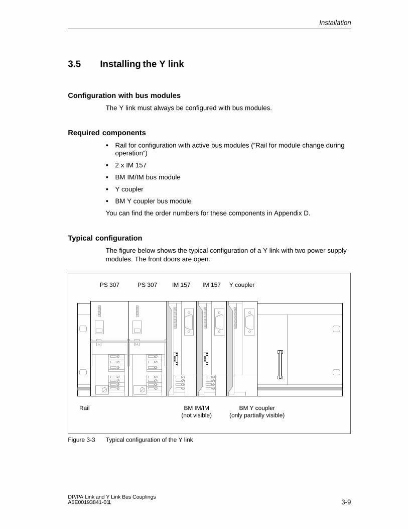
3.5 Installing the Y link
Configuration with bus modules
The Y link must always be configured with bus modules.
Required components
Rail for configuration with active bus modules (”Rail for module change duringoperation”)
2 x IM 157
BM IM/IM bus module
Y coupler
BM Y coupler bus module
You can find the order numbers for these components in Appendix D.
Typical configuration
The figure below shows the typical configuration of a Y link with two power supplymodules. The front doors are open.
PS 307 PS 307 IM 157 IM 157 Y coupler
BM IM/IM(not visible)
BM Y coupler(only partially visible)
Rail
Figure 3-3 Typical configuration of the Y link

Installation
3-10DP/PA Link and Y Link Bus Couplings
A5E00193841-011
IM 157 product release
For redundant operation, both IM 157 modules must have the same order numberand the same product release.
If the IM 157 (-0AA82-) is employed as a spare part for a precursor module, it canalso be used in the Y link together with an IM 157 with the order number -0AA81-.
Installing bus modules and modules
Install and remove the bus modules in a deenergized state as follows:
Step Activity
1 Hook the lower edge of the BM IM/IM bus module onto the rail, press it intothe rail (a) and push it to the left until it engages (b).
If you are using the 530 mm DIN rail and position the BM IM/IM in theright-hand latched position, you can install two additional PS 307; 2A or onePS 307; 5A to the left of the bus module.
Latchedposition
a b
2 Hook the BM Y coupler bus module onto the rail and press it down onto the rail.
3 Push the bus modules together so that the module connectors are in contact.
4 Insert both IM 157 in the BM IM/IM bus module.
5 Insert the Y coupler in the BM Y coupler bus module. Use the side guides of thebus modules to do this.
6 Tighten the bolts of the modules to secure them. This also fixes the busmodules to the rail.

Installation
3-11DP/PA Link and Y Link Bus Couplings A5E00193841-011
Removing and inserting modules
The modules can be inserted and removed during operation in redundancy modeon the S7-400H. The following special characteristics should be noted:
The insertion and removal of an IM 157 is only permissible if it is deenergized.Switch off the 24V DC power supply of the IM 157 to deenergize it. To preventfailure of the underlying master system, the Y link should be configured withpower supplies for the two IM 157 that can be switched independently of eachother (e. g. by using two power supply modules).
The Y coupler can be inserted/removed without restrictions. However, this willcause the connected nodes to fail.
Removing bus modules and modules
To remove the Y link, proceed as above but in reverse order.
If the device is already in operation, switch off the 24V DC power supply prior toremoval.

Installation
3-12DP/PA Link and Y Link Bus Couplings
A5E00193841-011

4-1DP/PA Link and Y Link Bus Couplings A5E00193841-011
Wiring
Overview of contents
This section contains general information on what to watch out for when you wirethe described modules and discusses the connections you will require.
How to wire the individual connections is described in subsections 4.3 to 4.5.
Section Topic Page
4.1 Electrical isolation and grounding 4-1
4.2 Connections 4-7
4.3 Connecting the power supply 4-11
4.4 Connecting PROFIBUS-DP 4-12
4.5 Connecting PROFIBUS-PA 4-12
4.1 Electrical isolation and grounding
Introduction
You can wire the 24V power supply for the described modules as a grounded orungrounded configuration, depending on the requirements of your systemconfiguration.
Features of the IM 157
The S7 backplane bus and the 24V power supply are electrically connected
The PROFIBUS-DP interface is electrically isolated from the 24V power supplyand the S7 backplane bus
Features of the DP/PA coupler
PROFIBUS-DP and PROFIBUS-PA are electrically isolated from the 24V powersupply of the DP/PA coupler
PROFIBUS-DP and PROFIBUS-PA are electrically isolated from each other
4

Wiring
4-2DP/PA Link and Y Link Bus Couplings
A5E00193841-011
Features of the Y coupler
The PROFIBUS-DP master system is electrically isolated from the S7backplane bus
4.1.1 General rules and regulations for operation
Introduction
When the described modules are used in a system, certain rules and regulationsmust be followed that depend on the area of application.
This section provides an overview of the most important rules that must beobserved for safe integration in a system.
Specific applications
Please comply with the safety and accident prevention regulations (e.g. machineprotection guidelines) that are valid for specific applications.
Emergency stop devices
Emergency stop functions in accordance with IEC 6204 (which corresponds toDIN VDE 113) must remain effective in all of the system’s operating modes.
Start-up of the system following specific events
The following table shows what you have to look out for when the system starts upafter certain events.
In the case of ... ...
The system starts up after a voltagedip or power failure
Start-up of the system afterinterruption of bus communication
Dangerous operating states must not be permittedto occur. If necessary, force an emergency stop!
The system starts up after theemergency stop system is reset
Start-up of the system without the DPmaster addressing the slaves
An uncontrolled or undefined start-up must not bepermitted to occur.
24V DC power supply
The following table shows what you have to look out for in the case of the 24Vsupply.

Wiring
4-3DP/PA Link and Y Link Bus Couplings A5E00193841-011
In the case of ... You must remember ...
Buildings External lightning protection Lightning protection
24V DC power supplycables, signal cables
Internal lightning protectionmeasures (e.g.lightning conductors)
24V supply Safety extra-low voltage with safe electrical isolation (SELV)
Protection from external electrical influences
The following table shows what you have to look out for to ensure protectionagainst electrical influences or faults.
In the case of ... You must ensure that ...
All systems in which themodules are integrated
... The system is connected to the protective conductor sothat electromagnetic interference can be discharged.
Connecting, signal and buslines
... The cable has been routed and installed correctly.
Signal and bus lines ... Line or conductor strand breaks do not lead toundefined system states.
Braided screen of the PROFIBUS cable
The braided screen of the PROFIBUS cable must be connected to a groundedshield bus.
Affix the braided screen with metal cable clips.
The clip must cover a large portion of the screen and provide good contact.
Connect the screen to a shield bus directly after the point where the cableenters the cabinet.
Cabinet
Figure 4-1 Braided screen of the PROFIBUS cable on the grounded shield bus

Wiring
4-4DP/PA Link and Y Link Bus Couplings
A5E00193841-011
4.1.2 Operation with a grounded supply
Definition: Grounded supply
In grounded supplies, the neutral conductor is grounded. A simple short-circuit toground between a voltage-carrying conductor and ground or a grounded part of thesystem leads to the protective devices being used.
Components and protective measures
Various components and protective measures are required for an overall system.The type of components used and the degree to which the protective measuresare mandatory depend on which regulations (e.g. DIN VDE in Germany) are validfor your system configuration.
Main switch (in Figure 4-2, ): DIN VDE 0100 Part 460
Isolator (in Figure 4-2, ): DIN VDE 0113 Part 1
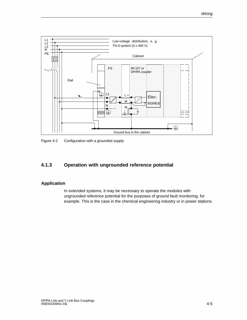
Operation with a grounded supply
Figure 4-2 shows the position of the modules in the overall configuration whenpower is supplied from a TN-S network. When the DP/PA coupler is configuredwith a grounded reference potential, any interference current is discharged to theprotective conductor.
Note: The arrangement of the power connections shown does not correspond tothe actual arrangement on the modules; it was selected in the interest of clarity.
Wiring
4-5DP/PA Link and Y Link Bus Couplings A5E00193841-011
Ground bus in the cabinet
N M
L1 L +
M
PS
L1L2L3N
Cabinet
Low-voltage distribution, e. g.TN-S system (3 x 400 V)
PE
Rail
IM 157 or DP/PA coupler
Elec-
tronics
Figure 4-2 Configuration with a grounded supply
4.1.3 Operation with ungrounded reference potential
Application
In extended systems, it may be necessary to operate the modules withungrounded reference potential for the purposes of ground fault monitoring, forexample. This is the case in the chemical engineering industry or in power stations.

Wiring
4-6DP/PA Link and Y Link Bus Couplings
A5E00193841-011
Diverting interference current
When modules are operated with ungrounded reference potential, any interferencecurrent is discharged to the protective conductor via RC networks that areintegrated in the IM 157 and the DP/PA coupler (see Figure 4-3).
M
L+
M
Ground bus
M22 nF 10 MΩ
Integrated RC network
Figure 4-3 Configuration with ungrounded reference potential
Wiring
4-7DP/PA Link and Y Link Bus Couplings A5E00193841-011
4.2 Connections
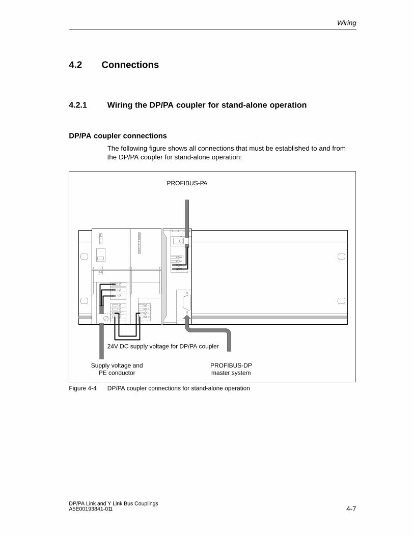
4.2.1 Wiring the DP/PA coupler for stand-alone operation
DP/PA coupler connections
The following figure shows all connections that must be established to and fromthe DP/PA coupler for stand-alone operation:
Supply voltage andPE conductor
24V DC supply voltage for DP/PA coupler
PROFIBUS-DPmaster system
PROFIBUS-PA
Figure 4-4 DP/PA coupler connections for stand-alone operation
Wiring
4-8DP/PA Link and Y Link Bus Couplings
A5E00193841-011
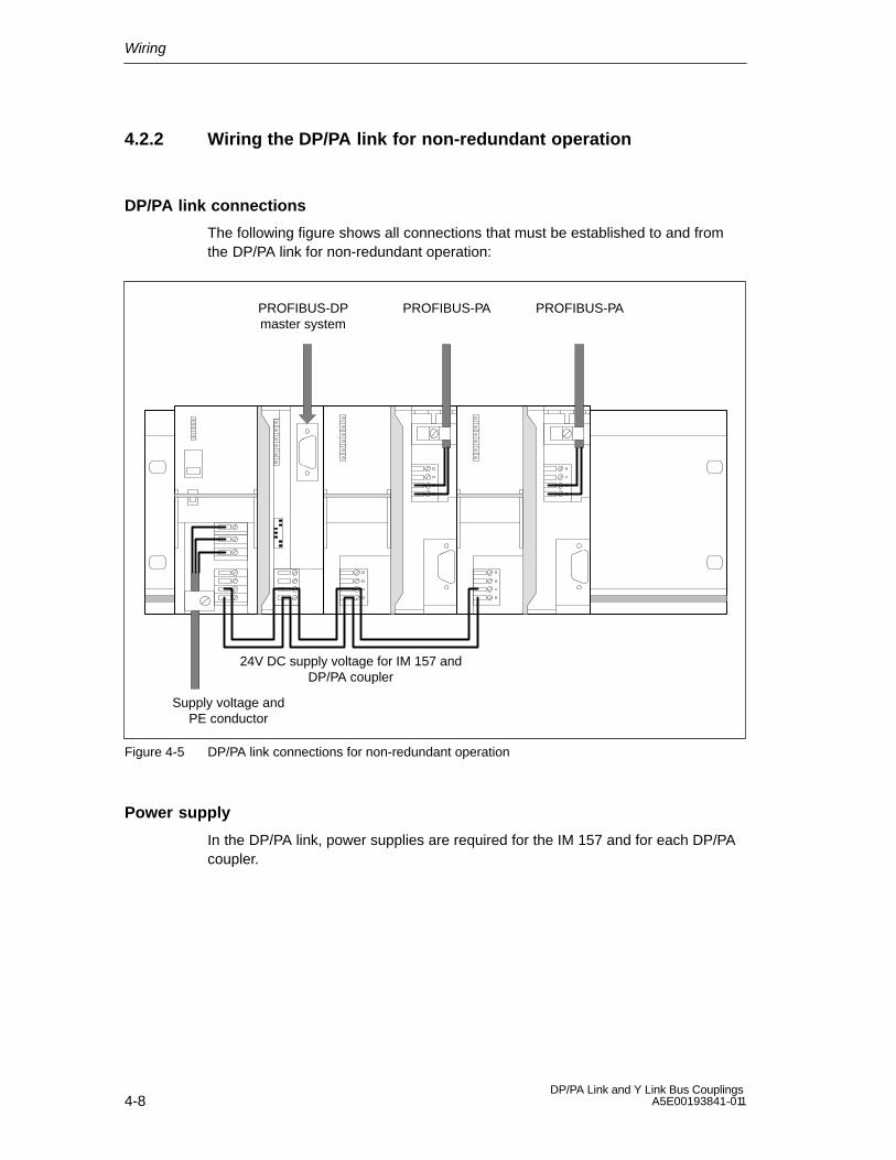
4.2.2 Wiring the DP/PA link for non-redundant operation
DP/PA link connections
The following figure shows all connections that must be established to and fromthe DP/PA link for non-redundant operation:
Supply voltage andPE conductor
24V DC supply voltage for IM 157 andDP/PA coupler
PROFIBUS-DPmaster system
PROFIBUS-PAPROFIBUS-PA
Figure 4-5 DP/PA link connections for non-redundant operation
Power supply
In the DP/PA link, power supplies are required for the IM 157 and for each DP/PAcoupler.

Wiring
4-9DP/PA Link and Y Link Bus Couplings A5E00193841-011
4.2.3 Wiring the DP/PA link for redundant operation
DP/PA link connections
The following figure shows all connections that must be established to and fromthe DP/PA link for redundant operation:
Supply voltage andPE conductor
24V DC supplyvoltage for IM 157
S7-400H
24V DC power supply for DP/PA coupler(optional external configuration)
PROFIBUS-PA
Figure 4-6 DP/PA link connections for redundancy operation
Power supply
In the DP/PA link, power supplies are required for both IM 157 and for each DP/PAcoupler.
PROFIBUS-DP
In the DP/PA link, PROFIBUS-DP connections to S7-400H are required for bothIM 157.

Wiring
4-10DP/PA Link and Y Link Bus Couplings
A5E00193841-011
4.2.4 Wiring the Y link
Y link connections
The following figure shows all connections that must be established to and fromthe Y link:
Supply voltage andPE conductor
24V DC supplyvoltage for IM 157 Underlying DP master
system
S7-400H
Figure 4-7 Y link connections
Power supply
In the Y-Link, power supplies are required for both IM 157.
PROFIBUS-DP
The following PROFIBUS-DP connections are required in the Y link:
To the S7-400H on both IM 157
To the underlying DP master system on the Y coupler

Wiring
4-11DP/PA Link and Y Link Bus Couplings A5E00193841-011
Bus terminating resistors
The Y coupler does not contain integrated bus terminating resistors. When the Ycoupler is arranged at the beginning or end of a bus segment, the bus terminatingresistors on the bus connector must be connected.
4.3 Connecting the power supply
The power supply is connected in the same manner for all described modules.
The connections that must be established between a power supply andcomponents are described in the subsections 4.2.1 to 4.2.4.
Required tool
To connect the power supply, you require a 3 mm screwdriver.
Power supply unit
You can only use power supply units of the type SELV with safe, electricallyisolated functional, extra-low ( 60V DC) voltage.
The size of the power supply unit depends on the current consumption of theconnected components (see Appendix B, Technical Data).
Power supply connection
The 4 pin screw-type terminal for the 24V voltage supply is found on the IM 157behind the front door at the bottom. The connections have the following functions:
M
L+
M
Functional groundRemovable bridge forungrounded configuration(see Section 4.1.3)
Ground
+24 V DC
Ground
Figure 4-8 Power supply for IM 157
The maximum conductor cross-section is 2.5 mm2. There is no cable grip.

Wiring
4-12DP/PA Link and Y Link Bus Couplings
A5E00193841-011
4.4 Connecting PROFIBUS-DP
The PROFIBUS-DP is connected in the same manner for all described modules.
The connections that must be established between a PROFIBUS-DP andcomponents are described in the subsections 4.2.1 to 4.2.4.
Required tool
To attach the bus connector to the IM 157, you require a 3 mm screwdriver.
Bus cable and connector
Only use the accessories specified in Appendix D for PROFIBUS-DP.
All of the information you will require on handling bus cables and connectors isprovided in the Distributed I/O System ET 200 handbook.
Procedure
Connect PROFIBUS-DP as follows:
1. Insert the bus connector into the PROFIBUS socket.
2. Tighten the screws on the bus connector.
4.5 Connecting PROFIBUS-PA
Important information
The following documentation is binding when installing the PROFIBUS-PA:
Untersuchungen zur Eigensicherheit bei Feldbus-Systemen (investigations intothe intrinsic safety of field bus fail-safe systems); PTB report W-53,Braunschweig, March 1993 (only relevant for installation in potentially explosiveareas).
PROFIBUS-PA Installation Guidelines (notes on using the IEC 1158-2 technology for PROFIBUS, German item no. 2.091, English item no. 2.092)PROFIBUS-Nutzerorganisation e. V., Haid-und-Neu-Straße 7, D-76131 Karlsruhe
Further information is available on the Internet:
http://www.profibus.com.
IEC 60079-14 stipulations on setting up electrical systems in potentiallyexplosive areas

Wiring
4-13DP/PA Link and Y Link Bus Couplings A5E00193841-011
Required tool
To connect PROFIBUS-PA, you require a 3 mm screwdriver.
We recommend that you use the PROFIBUS FastConnect tool to prepare thecables and lines (see Appendix D).
Bus cable
Use the bus cable specified in Appendix D for PROFIBUS-PA.
PROFIBUS-PA connection
The 4-pin screw-type terminal for the PROFIBUS-PA connection is found at the topof the DP/PA coupler under the right-hand front door. The connections have thefollowing functions:
Data line P+
Cable gripandshield support
Bus cable
Data line P–
DP/PA coupler Ex [i](6ES7 157-0AD81-0XA0)
Shield
Data line P+
Cable grip andshield support
Bus cable
Data line P–
DP/PA coupler(6ES7 157-0AC80-0XA0)
Shield
Data line P+ (loop through)Data line P– (loop through)
Looping through of PROFIBUS-PA: PA bus terminating switchPosition: OFF
OFF
ON
Bus cable (loop through)
Figure 4-9 PROFIBUS-PA connection

Wiring
4-14DP/PA Link and Y Link Bus Couplings
A5E00193841-011
PA Bus terminating switch
The PA bus terminating switch is only provided on the DP/PA coupler(6ES7 157-0AC80-0XA0). You can loop through the PROFIBUS-PA on this DP/PAcoupler only.
The bus terminating resistor cannot be deactivated in the DP/PA coupler Ex [i], i. e.the DP/PA coupler Ex [i] must be located at the beginning or end of a PA segment.
DP/PA coupler(6ES7 157-0AC80-0XA0)
PA bus terminating switch
OFF
ON
OFF: The bus terminating resistors are deactivated.You can loop through the PROFIBUS-PA and con-nect bus terminating resistors to both ends of thePA segment.
ON: The bus terminating resistors are activated.PROFIBUS-PA must not be looped through.
Figure 4-10 PA bus terminating switch
Procedure
Connect PROFIBUS-PA as follows:
1. Strip the insulation from the cable, turning the braided screen back over theinsulation as shown below.
Turn the braided screen back over the insulation.
15 mm 60 mm
10 mm
Figure 4-11 Length of insulation stripped
2. Clamp the shield of the bus cable under the cable grip and screw it tight.
3. Secure the conductors of the bus cable in the screw-type terminals P+ and P–.Be sure to get the polarity of the conductors right.

5-1DP/PA Link and Y Link Bus Couplings A5E00193841-011
Commissioning the DP/PA Coupler forStand-Alone Operation
The DP/PA coupler is ready for operation when you have completed the setup andwiring of the coupler as described in Sections 3 and 4 and have switched on thepower supply.
A transmission rate of 45.45 kBaud should be set for the DP master.
5

Commissioning the DP/PA Coupler for Stand-Alone Operation
5-2DP/PA Link and Y Link Bus Couplings
A5E00193841-011
6-1DP/PA Link and Y Link Bus Couplings A5E00193841-011
Commissioning the DP/PA Link
Overview of contents
This chapter describes the steps involved in commissioning the DP/PA link. Adetailed explanation of these steps is found in the individual subsections.
Section Topic Page
6.1 Commissioning the DP/PA link 6-2
6.2 Configuration for the S7 standard operation or redundancy operation 6-3
6.3 Configuration for the DP standard master operation 6-6
6.4 Setting the PROFIBUS address of the IM 157 6-10
6

Commissioning the DP/PA Link
6-2DP/PA Link and Y Link Bus Couplings
A5E00193841-011
6.1 Commissioning the DP/PA link
Prerequisites
The following prerequisites must be met before you commission the DP/PA link:
You must have completed the setup and wiring of the DP/PA link as describedin Sections 3 and 4.
You must have completed the setup of PROFIBUS-DP. PROFIBUS-DP must beready for operation.
You must have completed the setup of PROFIBUS-PA. PROFIBUS-PA must beready for operation.
Commissioning the DP/PA link
Step Activity
1 Configure the DP/PA link.
2 Set the PROFIBUS address of the IM 157.
3 Switch on the power supply for the DP/PA link.
4 Load the configuration into the target system.
Configuring the DP/PA link
The DP/PA link is configured with STEP 7 for S7 standard operation and forredundant operation.
For the DP standard master operation, the DP/PA link is configured via thedevice master file, e.g. with COM PROFIBUS.
The DP/PA couplers are gateways between the S7 backplane bus of the IM 157and PROFIBUS-PA with the PA field devices. Therefore, the DP/PA coupler doesnot have to be configured.
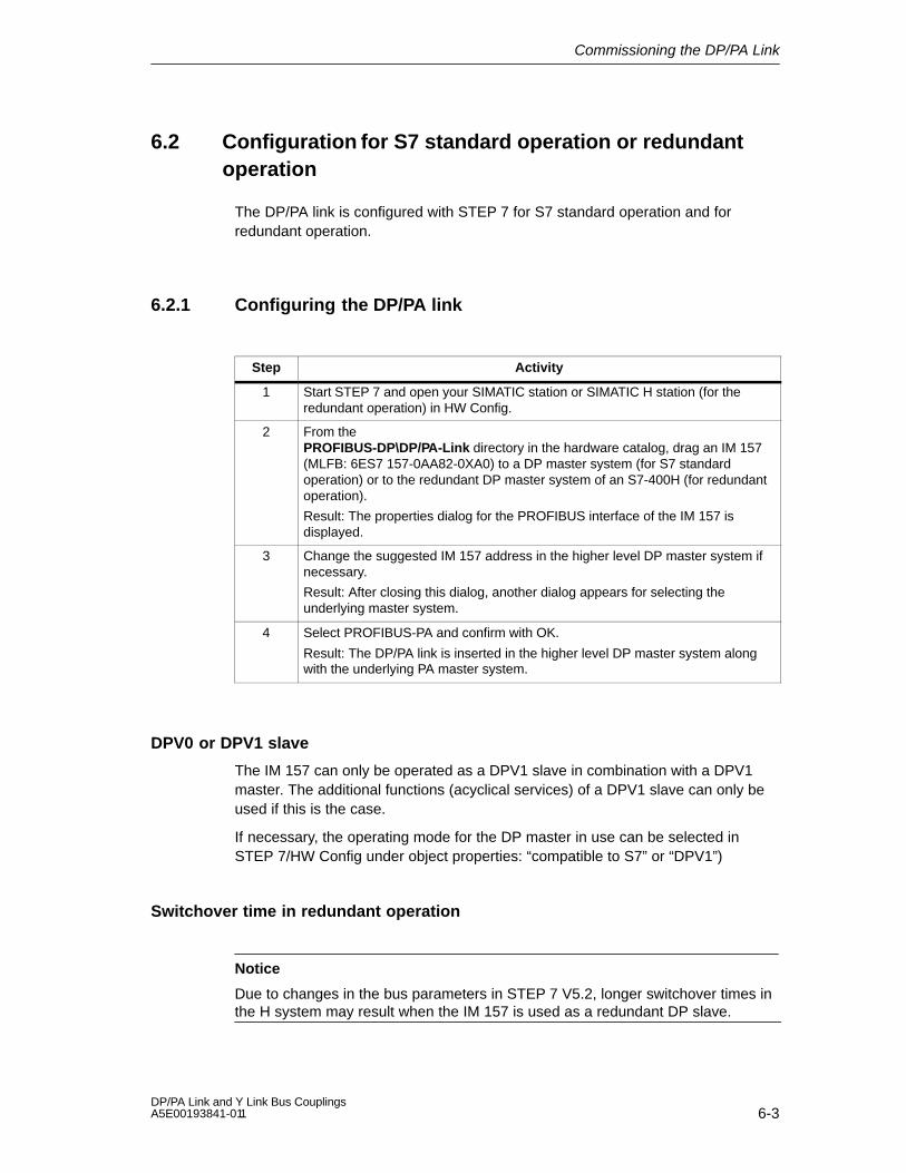
Commissioning the DP/PA Link
6-3DP/PA Link and Y Link Bus Couplings A5E00193841-011
6.2 Configuration for S7 standard operation or redundantoperation
The DP/PA link is configured with STEP 7 for S7 standard operation and forredundant operation.
6.2.1 Configuring the DP/PA link
Step Activity
1 Start STEP 7 and open your SIMATIC station or SIMATIC H station (for theredundant operation) in HW Config.
2 From thePROFIBUS-DP\DP/PA-Link directory in the hardware catalog, drag an IM 157(MLFB: 6ES7 157-0AA82-0XA0) to a DP master system (for S7 standardoperation) or to the redundant DP master system of an S7-400H (for redundantoperation).
Result: The properties dialog for the PROFIBUS interface of the IM 157 isdisplayed.
3 Change the suggested IM 157 address in the higher level DP master system ifnecessary.
Result: After closing this dialog, another dialog appears for selecting theunderlying master system.
4 Select PROFIBUS-PA and confirm with OK.
Result: The DP/PA link is inserted in the higher level DP master system alongwith the underlying PA master system.
DPV0 or DPV1 slave
The IM 157 can only be operated as a DPV1 slave in combination with a DPV1master. The additional functions (acyclical services) of a DPV1 slave can only beused if this is the case.
If necessary, the operating mode for the DP master in use can be selected inSTEP 7/HW Config under object properties: “compatible to S7” or “DPV1”)
Switchover time in redundant operation
Notice
Due to changes in the bus parameters in STEP 7 V5.2, longer switchover times inthe H system may result when the IM 157 is used as a redundant DP slave.

Commissioning the DP/PA Link
6-4DP/PA Link and Y Link Bus Couplings
A5E00193841-011
Example of the configuration of a DP/PA link for redundant operation
Figure 6-1 HW Config: DP/PA link in hardware catalog
Figure 6-2 HW Config: Minimum configuration of an S7-400H with a DP/PA link
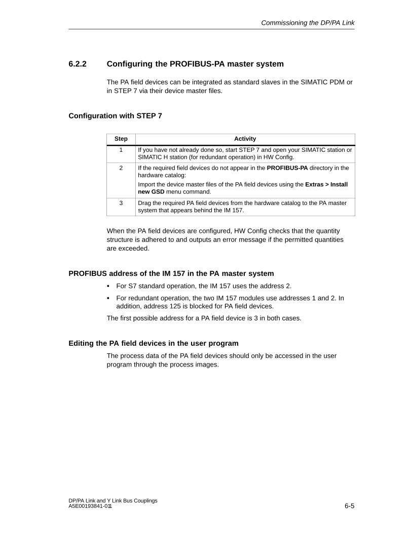
Commissioning the DP/PA Link
6-5DP/PA Link and Y Link Bus Couplings A5E00193841-011
6.2.2 Configuring the PROFIBUS-PA master system
The PA field devices can be integrated as standard slaves in the SIMATIC PDM orin STEP 7 via their device master files.
Configuration with STEP 7
Step Activity
1 If you have not already done so, start STEP 7 and open your SIMATIC station orSIMATIC H station (for redundant operation) in HW Config.
2 If the required field devices do not appear in the PROFIBUS-PA directory in thehardware catalog:
Import the device master files of the PA field devices using the Extras > Installnew GSD menu command.
3 Drag the required PA field devices from the hardware catalog to the PA mastersystem that appears behind the IM 157.
When the PA field devices are configured, HW Config checks that the quantitystructure is adhered to and outputs an error message if the permitted quantitiesare exceeded.
PROFIBUS address of the IM 157 in the PA master system
For S7 standard operation, the IM 157 uses the address 2.
For redundant operation, the two IM 157 modules use addresses 1 and 2. Inaddition, address 125 is blocked for PA field devices.
The first possible address for a PA field device is 3 in both cases.
Editing the PA field devices in the user program
The process data of the PA field devices should only be accessed in the userprogram through the process images.

Commissioning the DP/PA Link
6-6DP/PA Link and Y Link Bus Couplings
A5E00193841-011
6.3 Configuration for DP standard master operation
For DP standard master operation, the DP/PA link and the PA field devices areconfigured using device master files, e.g. with COM PROFIBUS.
6.3.1 Device master files
A template file that can be used to generate the finished device master file wascreated for the DP/PA link. This template does not yet contain any module IDs forPA field devices.
Module IDs must be entered in the device master file for every PA field device thatyou wish to use in the DP/PA link. A software tool (”GSD tool for IM 157”) isavailable for this purpose.
You can download the imlinkv1.dat template and the GSD tool free of charge at thefollowing Internet address:
http://www.ad.siemens.de/csi_e/gsd
There you will also find the device master files of the PA field devices offered bySiemens AG.
Creating a device master file
Load the imlinkv1.dat template and the GSD tool from the Internet address givenabove and follow the accompanying instructions.
For the DP/PA link, the GSD tool creates a device master file, sir48052.gsd, fromthe imlinkv1.dat template and from the device master files you added for the PAfield devices to be used.

Commissioning the DP/PA Link
6-7DP/PA Link and Y Link Bus Couplings A5E00193841-011
6.3.2 Configuring the DP/PA link
Configure the DP/PA link with your configuration tool (e. g. COM PROFIBUS) asyou would any other DP slave on PROFIBUS-DP.
To do so, load the complete device master file for the DP/PA link into yourconfiguration tool.
Parameter assignment and configuration frame
The frame length for the parameter assignment depends on the number of PA fielddevices in use and must not exceed 214 bytes.
The frame length for the configuration depends on the number and extent of PAfield devices in use and must not exceed 244 bytes.
The structure of the parameter assignment and configuration frames is found inArticle No. 13406349 on the Internet:
http://www.ad.siemens.de/simatic-cs
Restrictions
Functions based on reading the configuration before parameters are initiallyassigned to the DP/PA link are not supported. For this reason the CP 5431, forexample, cannot be used as a DP master. Likewise, variables cannot be controlledwith the COM PROFIBUS before parameters have been assigned for the DP/PAlink.
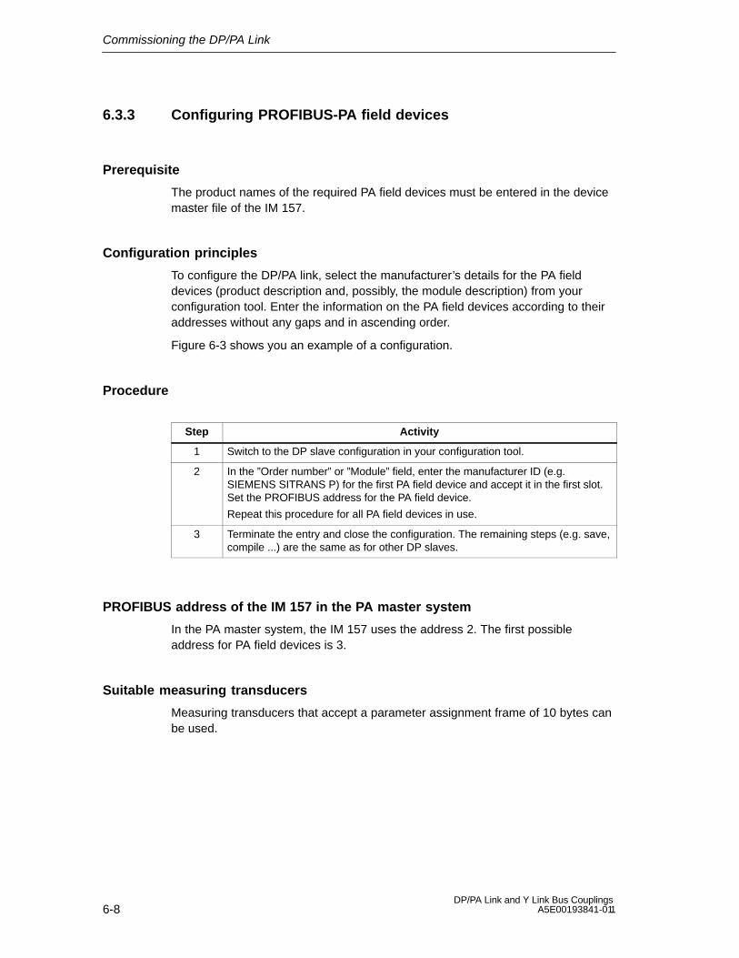
Commissioning the DP/PA Link
6-8DP/PA Link and Y Link Bus Couplings
A5E00193841-011
6.3.3 Configuring PROFIBUS-PA field devices
Prerequisite
The product names of the required PA field devices must be entered in the devicemaster file of the IM 157.
Configuration principles
To configure the DP/PA link, select the manufacturer’s details for the PA fielddevices (product description and, possibly, the module description) from yourconfiguration tool. Enter the information on the PA field devices according to theiraddresses without any gaps and in ascending order.
Figure 6-3 shows you an example of a configuration.
Procedure
Step Activity
1 Switch to the DP slave configuration in your configuration tool.
2 In the ”Order number” or ”Module” field, enter the manufacturer ID (e.g.SIEMENS SITRANS P) for the first PA field device and accept it in the first slot.Set the PROFIBUS address for the PA field device.
Repeat this procedure for all PA field devices in use.
3 Terminate the entry and close the configuration. The remaining steps (e.g. save,compile ...) are the same as for other DP slaves.
PROFIBUS address of the IM 157 in the PA master system
In the PA master system, the IM 157 uses the address 2. The first possibleaddress for PA field devices is 3.
Suitable measuring transducers
Measuring transducers that accept a parameter assignment frame of 10 bytes canbe used.
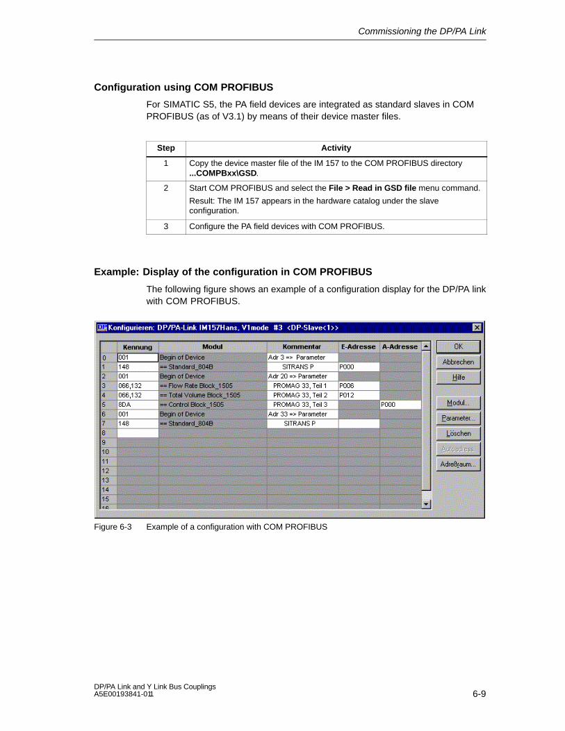
Commissioning the DP/PA Link
6-9DP/PA Link and Y Link Bus Couplings A5E00193841-011
Configuration using COM PROFIBUS
For SIMATIC S5, the PA field devices are integrated as standard slaves in COMPROFIBUS (as of V3.1) by means of their device master files.
Step Activity
1 Copy the device master file of the IM 157 to the COM PROFIBUS directory...COMPBxx\GSD.
2 Start COM PROFIBUS and select the File > Read in GSD file menu command.
Result: The IM 157 appears in the hardware catalog under the slaveconfiguration.
3 Configure the PA field devices with COM PROFIBUS.
Example: Display of the configuration in COM PROFIBUS
The following figure shows an example of a configuration display for the DP/PA linkwith COM PROFIBUS.
Figure 6-3 Example of a configuration with COM PROFIBUS

Commissioning the DP/PA Link
6-10DP/PA Link and Y Link Bus Couplings
A5E00193841-011
Setting the PROFIBUS address
1. In the Module column, select the Begin of Device item for the respective PAfield device and select the Parameters...
2. button
3. In the Value column, enter the required PROFIBUS address and confirm withOK.
Figure 6-4 Entering the PROFIBUS address
6.4 Setting the PROFIBUS address of the IM 157
Definition
Each bus node must receive a PROFIBUS address so that it can be uniquelyidentified on PROFIBUS-DP.
Rules
The following rules apply to the PROFIBUS address of the IM 157 in the higherlevel DP master system:
The valid PROFIBUS addresses are: 1 to 125.
Each PROFIBUS address can only be assigned once in a DP master system.
For redundant operation, the same PROFIBUS address must be set for bothIM 157 modules.
Required tool
To set the PROFIBUS address, you require a 3 mm screwdriver.
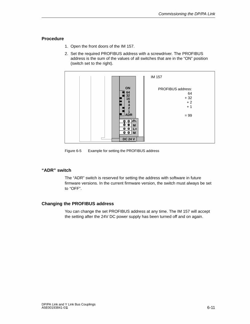
Commissioning the DP/PA Link
6-11DP/PA Link and Y Link Bus Couplings A5E00193841-011
Procedure
1. Open the front doors of the IM 157.
2. Set the required PROFIBUS address with a screwdriver. The PROFIBUSaddress is the sum of the values of all switches that are in the “ON” position(switch set to the right).
643216
8421
ON
ML+M
DC 24 V
PROFIBUS address:64
+ 32+ 2+ 1
= 99
IM 157
ADR
Figure 6-5 Example for setting the PROFIBUS address
“ADR” switch
The “ADR” switch is reserved for setting the address with software in futurefirmware versions. In the current firmware version, the switch must always be setto “OFF”.
Changing the PROFIBUS address
You can change the set PROFIBUS address at any time. The IM 157 will acceptthe setting after the 24V DC power supply has been turned off and on again.

Commissioning the DP/PA Link
6-12DP/PA Link and Y Link Bus Couplings
A5E00193841-011

7-1DP/PA Link and Y Link Bus Couplings A5E00193841-011
Commissioning the Y Link
Overview of contents
This chapter describes the steps involved in commissioning the Y link. A detailedexplanation of these steps is found in subsections 7.2 and 7.3
Section Topic Page
7.1 Commissioning the Y link 7-1
7.2 Configuring the Y link 7-2
7.3 Configuring the underlying DP slaves 7-4
7.1 Commissioning the Y link
Prerequisites
The following prerequisites must be met before you commission the Y link:
You must have completed the setup and wiring of the DP/PA link as describedin Sections 3 and 4.
You must have completed the setup of the H system and the redundant DPmaster system. PROFIBUS-DP must be ready for operation.
You must have completed the setup of the underlying DP master system andhave connected it to the Y coupler. PROFIBUS-DP must be ready for operation.
Commissioning the Y link
Step Activity
1 Configure the Y link.
2 Configure the underlying DP slaves.
3 Switch on the power supply for the Y link.
4 Set the PROFIBUS address of the IM 157 (see Section 6.4).
5 Load the configuration into the target system.
7
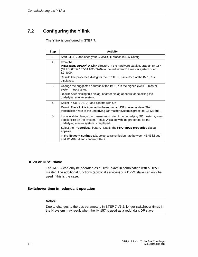
Commissioning the Y Link
7-2DP/PA Link and Y Link Bus Couplings
A5E00193841-011
7.2 Configuring the Y link
The Y link is configured in STEP 7.
Step Activity
1 Start STEP 7 and open your SIMATIC H station in HW Config.
2 From thePROFIBUS-DP\DP/PA-Link directory in the hardware catalog, drag an IM 157(MLFB: 6ES7 157-0AA82-0XA0) to the redundant DP master system of anS7-400H.
Result: The properties dialog for the PROFIBUS interface of the IM 157 isdisplayed.
3 Change the suggested address of the IM 157 in the higher level DP mastersystem if necessary.
Result: After closing this dialog, another dialog appears for selecting theunderlying master system.
4 Select PROFIBUS-DP and confirm with OK.
Result: The Y link is inserted in the redundant DP master system. Thetransmission rate of the underlying DP master system is preset to 1.5 MBaud.
5 If you wish to change the transmission rate of the underlying DP master system,double click on the system. Result: A dialog with the properties for theunderlying master system is displayed.
Select the Properties... button. Result: The PROFIBUS properties dialogappears.
In the Network settings tab, select a transmission rate between 45.45 kBaudand 12 MBaud and confirm with OK.
DPV0 or DPV1 slave
The IM 157 can only be operated as a DPV1 slave in combination with a DPV1master. The additional functions (acyclical services) of a DPV1 slave can only beused if this is the case.
Switchover time in redundant operation
Notice
Due to changes to the bus parameters in STEP 7 V5.2, longer switchover times inthe H system may result when the IM 157 is used as a redundant DP slave.

Commissioning the Y Link
7-3DP/PA Link and Y Link Bus Couplings A5E00193841-011
Example of a configuration of a Y link
Figure 7-1 HW Config: Y link in hardware catalog
Figure 7-2 HW Config: Minimum configuration of an S7-400H with a Y link
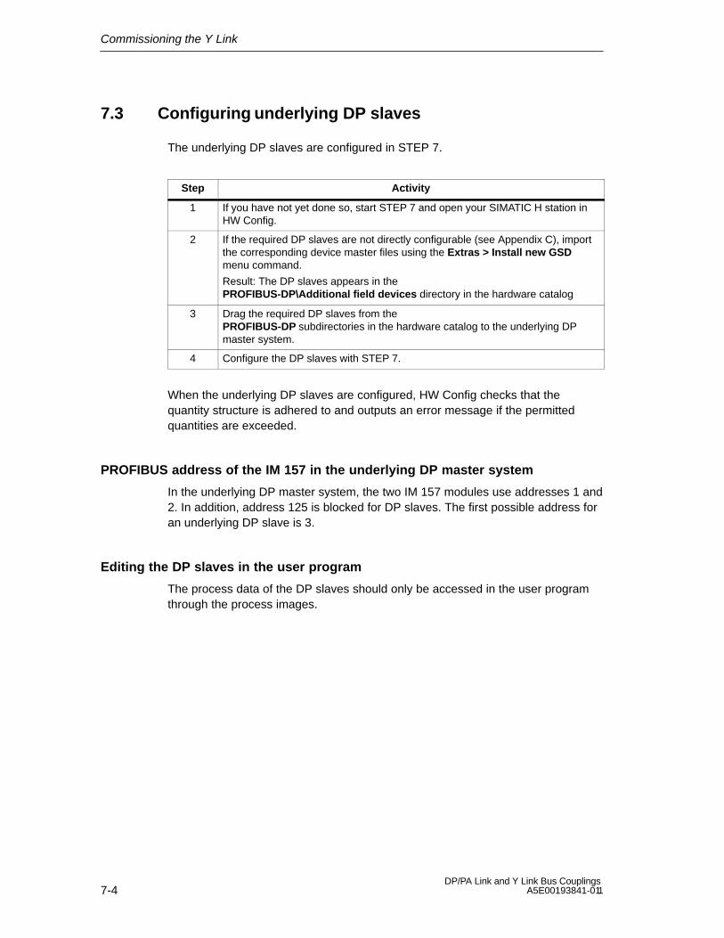
Commissioning the Y Link
7-4DP/PA Link and Y Link Bus Couplings
A5E00193841-011
7.3 Configuring underlying DP slaves
The underlying DP slaves are configured in STEP 7.
Step Activity
1 If you have not yet done so, start STEP 7 and open your SIMATIC H station inHW Config.
2 If the required DP slaves are not directly configurable (see Appendix C), importthe corresponding device master files using the Extras > Install new GSDmenu command.
Result: The DP slaves appears in the PROFIBUS-DP\Additional field devices directory in the hardware catalog
3 Drag the required DP slaves from the PROFIBUS-DP subdirectories in the hardware catalog to the underlying DPmaster system.
4 Configure the DP slaves with STEP 7.
When the underlying DP slaves are configured, HW Config checks that thequantity structure is adhered to and outputs an error message if the permittedquantities are exceeded.
PROFIBUS address of the IM 157 in the underlying DP master system
In the underlying DP master system, the two IM 157 modules use addresses 1 and2. In addition, address 125 is blocked for DP slaves. The first possible address foran underlying DP slave is 3.
Editing the DP slaves in the user program
The process data of the DP slaves should only be accessed in the user programthrough the process images.

8-1DP/PA Link and Y Link Bus Couplings A5E00193841-011
Operation of the DP/PA Link and theY Link
Overview of contents
Section Topic Page
8.1 Start-up delay 8-1
8.2 Start-up characteristics 8-2
8.3 Behavior following specific events in redundant operation 8-6
8.4 Reading and writing records 8-7
8.5 Identification data 8-9
8.6 Replacing faulty modules 8-11
8.7 System changes during operation 8-11
8.8 IM 157 firmware update 8-12
Some of the following details apply to both the DP/PA link with its PA field devicesand to the Y link with its underlying DP slaves. In these instances, the followingterminology will be used in the interest of clarity:
“Link” stands for both the DP/PA link and the Y link.
“Slaves” stands for both the PA field devices and the underlying DP slaves.
“Underlying master system” stands for both the PA master system and theunderlying DP master system.
8.1 Start-up delay
During start-up, the link involves the slaves of the underlying master system in thedata cycle. The slaves are parameterized and configured and the inputs of theslaves are read in.
To ensure a reproducible start-up and to avoid unintentional switching of theoutputs, the link issues CLEAR frames on the underlying master system during thisphase, i.e. the outputs of the slaves are put into a safe state.
Start-up behavior depends on the configured start-up characteristics of the systemconfiguration:
8

Operation of the DP/PA Link and the Y Link
8-2DP/PA Link and Y Link Bus Couplings
A5E00193841-011
Table 8-1 Configured start-up characteristics
Configured start-upcharacteristics
The output data is issued by the link if...
Start-up when the desired layout actual layout
All slaves are parameterized and configured, or
The startup delay has expired and fewer slaveswere parameterized/configured than planned.
Start-up when the desired layout= actual layout
All the slaves are parameterized and configured.
Note: If not all slaves are configured or parameterized withinthe power-up delay time, the link automatically repeatsstart-up.
The status of the start-up delay can be evaluated in the ”Status Message”diagnostic block of the diagnostic frame.
8.2 Start-up characteristics
Prerequisites for starting up the IM 157
A valid PROFIBUS address must be set on the IM 157.
The DP master on the higher level PROFIBUS-DP must be in operation.
The link must be configured correctly.
The further behavior of the DP/PA link depends on whether it is in redundant ornon-redundant operation.
8.2.1 Start-up behavior of the DP/PA link in non-redundant operation
The flow chart below shows the start-up behavior of the IM 157 after the power isswitched on.

Operation of the DP/PA Link and the Y Link
8-3DP/PA Link and Y Link Bus Couplings A5E00193841-011
Yes
The IM 157 enters the DP data cycle and is configured by the DP master.
Power-up of the IM 157 (schematic)
Power on at the IM 157
Bit x+43.0 = 1 in diagnostic frame, i. e. the start-up delay of the IM 157 is active.
PROFIBUS-PA: IM 157 reads (as far as possible) the PA input data.PA output data are set to ”0” (CLEAR). Missing slaves are read in with a ”0”.
All slaves in the data cycle (bitx+43.1=“1” in the diagnostic frame) or
start-up delay time elapsed?
No
Bit x+43.0 is set to 0
Configuration: Start-up if ...
Did the IM 157 involve all slaves in the data cycle during
the power-up delay time?
Actual desired
Actual = desired
Yes
IM 157 reads the PA input data.PA output data are passed on to the slaves.
Bit x+43.0 = ”1”: start-up delay activeBit x+43.1 = ”1”: all slaves in data exchange In S7 operation: x = 100
No
The IM 157 exits the DP and PA datacycle.
Figure 8-1 Start-up behavior of the IM 157 after power is switched on

Operation of the DP/PA Link and the Y Link
8-4DP/PA Link and Y Link Bus Couplings
A5E00193841-011
8.2.2 Start-up behavior in redundant operation
LED displays
At the beginning of start-up, all LEDs of the IM 157 light up for approx. 1 secondfor test purposes.

Operation of the DP/PA Link and the Y Link
8-5DP/PA Link and Y Link Bus Couplings A5E00193841-011
Startup diagram of the IM 157
During start-up, the two IM 157 modules are addressed independently of oneanother:
Each DP master configures and parameterizes its IM 157 (independently of theother DP master) and sends the corresponding configuration.
During error-free operation, the IM 157 that is connected to the subsystem ofthe master CPU is activated.
As soon as the other DP master has also configured and parameterized itsIM 157 without errors and sent the entire configuration, the IM 157 is madeavailable on standby.
The IM 157 at the subsystem of the reserve CPU is passive. If the activeIM 157 fails, it is still able to continue processing the slaves.
Figure 8-2 shows a simplified layout of the mutually independent behavior of thetwo IM 157.
IM 157 on the subsystem of the masterCPU
The DP master configures andparameterizes the IM 157 and sends theconfiguration.
IM 157 on the subsystem of the reserveCPU
The IM 157 is completely parameterized andconfigured and has received theconfiguration
The DP master activates the IM 157.
The ”ACT” LED comes on.
The DP master configures andparameterizes the IM 157 and sends theconfiguration.
The IM 157 is completely parameterized andconfigured and has received theconfiguration
The IM 157 is activated and engages in dataexchange with the slaves.
The ”SF” and ”BF 2” LEDs go out.
The IM 157 is ready for a data exchangewith the slaves and is on standby for aswitchover should it become necessary.
Figure 8-2 Start-up behavior of the two IM 157 modules in redundant operation

Operation of the DP/PA Link and the Y Link
8-6DP/PA Link and Y Link Bus Couplings
A5E00193841-011
8.3 Behavior following specific events in redundantoperation
The table below shows the behavior of the IM 157 following specific events inredundant operation.
Table 8-2 Behavior following specific events in redundant operation
Event Reaction
Master-reserve switchover with a changedconfiguration
The link is switched over in a bumplessmanner from the active channel to thechannel that has up to now been passive.
Failure of a CPU If this also causes the active channel of theredundant DP master system to fail: seeFailure of the active channel.
Otherwise: see Failure of the passivechannel.
Failure of the active channel The link is switched over in a bumplessmanner from the active channel to thechannel that has up to now been passive.
The failed channel is indicated on thecorresponding IM 157 by the “BF 1” LED.
Failure of the passive channel No consequences for the link.
The failed channel is indicated on thecorresponding IM 157 by the “BF 1” LED.
Failure of an IM 157 A diagnostic message is generated in thesystem.
If the active IM 157 fails, the link is switchedover in a bumpless manner to the channelthat has up to now been passive.

Operation of the DP/PA Link and the Y Link
8-7DP/PA Link and Y Link Bus Couplings A5E00193841-011
8.4 Reading and writing records
Depending on the operating mode of the DP master (S7-compatible or DPV1),records of the IM 157 and the underlying slaves can be read and written bydifferent methods.
Reading records with SFC 59 “RD_REC” or SFB 52 “RDREC”
Writing records with SFC 58 “WR_REC” or SFB 53 “WRREC”
Reading and writing records with a programming device/PC via communicationlinks, e.g. with SIMATIC PDM
Table 8-3 Methods for reading and writing records
S7-compatible DP master DPV1 master
Records of the IM 157 SFC 59 “RD_REC”
Read with programmingdevice/PC
SFC 59 “RD_REC”,SFB 52 “RDREC”
SFC 58 “WR_REC”,SFB 53 “WRREC”
Read/write withprogramming device/PC
Records of underlyingslaves
Read/write withprogramming device/PC
SFC 59 “RD_REC”,SFB 52 “RDREC”
SFC 58 “WR_REC”,SFB 53 “WRREC”
Read/write withprogramming device/PC
Records of the IM 157
Depending on the operating mode of the DP master (S7-compatible or DPV1), theIM 157 support reading and writing of the following records:
On the DPV1 master:
– Records 0 and 1 (diagnostic data, read only)
– Records 248 … (identification data, see Section 8.5)
On the S7-compatible master
– Records 0 and 1 (diagnostic data, read only)

Operation of the DP/PA Link and the Y Link
8-8DP/PA Link and Y Link Bus Couplings
A5E00193841-011
Parameters for SFC 58 ”WR_REC” and SFC 59 ”RD_REC”
The table below shows the required values for the call parameters, LADDR andREC_NUM, and the error information that may be found in the return value,RET_VAL.
Table 8-4 Call parameters for SFC 58 ”WR_REC” and SFC 59 ”RD_REC”
LADDR REC_NUM Access
Diagnostic data of the IM 157 Diagnostic address of theIM 157
0 or 1 Read only
Identification data of theIM 157
Diagnostic address of theIM 157
248 … (see Section 8.5) Read/write
Buffered diagnostic data of anunderlying slave (from theIM 157) 1)
Diagnostic address of theIM 157
PROFIBUS address of theunderlying slave
Read only
Any record of an underlyingDPV1 slave
Logical address of theunderlying slave or theunderlying module
Record number 2) Read/write 2)
1) Only on the DPV1 master and only for configured slaves2) Depends on type of underlying slave or underlying module
Table 8-5 Error information of the IM 157
RET_VAL (W#16#) Description
0000 No error
80BB Requested service is not supported
80BC Node not available
80BD Record number or faulty
The additional functions of the SFC 58 ”WR_REC”, SFC 59 ”RD_REC”, SFB 52“RDREC” and SFB 53 “WRREC” are described in the STEP 7 online help.

Operation of the DP/PA Link and the Y Link
8-9DP/PA Link and Y Link Bus Couplings A5E00193841-011
8.5 Identification data
Identification data is the information that is stored in a module and that supportsthe user in the following tasks:
Eliminating errors in a system
Checking the system configuration
Locating hardware changes in a system
The identification data can be used to positively identify modules online.
Reading the identification data
You can access the identification data via “Read record”. The data is accessed intwo steps:
1. A directory stored in record 248 lists the record numbers corresponding to thevarious indexes.
2. Part of the identification data is found under the respective index.
The identification data is assigned to the indexes as specified in Table 8-6.
In non-redundant operation, STEP 7 provides a convenient means of readingidentification data.
Table 8-6 Identification data
Identification data Access Default setting Explanation
Index 1 (record 234)
Manufacturer Read(2 bytes)
2A hex (= 42 dec) The name of the manufacturer isstored here.(42 dec = Siemens AG)
Device name Read(20 bytes)
6ES7 157-0AA82-0XA0 Module order number
Device serial number Read(16 bytes)
Depends on productrelease
The module serial number is storedhere. This allows positive identificationof the module.
Hardware version Read(2 bytes)
Provides information on the productrelease of the module. Is incremented ifthe product release and/or the firmwareof the module changes.
Software version Read(4 bytes)
Provides information on the firmwareversion of the module. If the firmwareversion is increment, the productrelease (hardware version) of themodule also increases.
Statisticalversion no..
Read(2 bytes)
– Provides information on parameterizedchanges on the module. The statisticalversion no. is incremented after eachchange.

Operation of the DP/PA Link and the Y Link
8-10DP/PA Link and Y Link Bus Couplings
A5E00193841-011
Table 8-6 Identification data
Identification data ExplanationDefault settingAccess
Index 2 (record 235)
TAG Read/write(max. of 64characters)
– Module location identifier. Enter a code for the module that isunique throughout the entire system.
Index 3 (record 236)
Installation date Read/write(max. of 64characters)
– Contains the date on which the modulewas installed. Enter the date here. Format YYYY-MM-DD
Index 4 (record 237)
Description Read/write(max. of 64characters)
– Contains the module order number andspace for text. You can enter additionalinformation on the features of themodule here.
AttentionOverwriting the order number maymake it impossible to address theIM 157.

Operation of the DP/PA Link and the Y Link
8-11DP/PA Link and Y Link Bus Couplings A5E00193841-011
8.6 Replacing faulty modules
The table below show the steps necessary to replace a faulty IM 157, a faultyDP/PA coupler or a faulty Y coupler.
Step Activity
1 Disconnect the power supply of the faulty module.
2 Unplug the bus connector from the PROFIBUS-DP interface of the faultymodule.
Or
Disconnect the PROFIBUS-PA connection of the faulty DP/PA coupler.
3 Replace the faulty module.
4 Connect the bus connector with the PROFIBUS-DP interface of the newmodule.
Or
Connect the PROFIBUS-PA interface to the new DP/PA coupler.
5 Connect the power supply of the new module.
Information on compatibility regarding the exchange of modules is found inAppendix 2.7.
8.7 System changes during operation
8.7.1 System changes in S7 standard operation
The table below shows the steps necessary to add a completely new DP/PA linktogether with the underlying PA master system to an existing system duringoperation.
Step Activity
1 Install the new DP/PA link.
2 Connect the power supply of all modules.
3 Connect the PROFIBUS-PA to the new DP/PA coupler.
4 Connect the bus connector of the DP master system to the PROFIBUS-DPinterface of the new IM 157.
The overall procedure for making a system change and the prerequisites that mustbe met to do so are described in detail in the function manual, System Changesduring Operation via CiR.

Operation of the DP/PA Link and the Y Link
8-12DP/PA Link and Y Link Bus Couplings
A5E00193841-011
8.7.2 System changes in redundant operation
The table below shows the steps necessary to add a completely new DP/PA link orY link together with the underlying master system to an existing system duringoperation.
Step Activity
1 Install the new link.
2 Connect the power supply of all modules.
3 DP/PA link only
Connect the PROFIBUS-PA to the newDP/PA coupler.
Y link only
Connect the bus connector of theunderlying DP master system to thePROFIBUS-DP interface of the new Ycoupler.
4 Connect the bus connector of the active channel of the redundant DP mastersystem to the PROFIBUS-DP interface of one of the two IM 157 modules.
5 Connect the bus connector of the passive channel to the PROFIBUS-DPinterface of the other IM 157.
This procedure is summarized under “Reconfiguring hardware” in the sectionentitled “System changes during operation” in the S7-400H Automation System,High-Availability Systems manual. Here you will also find a detailed description ofthe overall procedure for making a system change.
8.8 IM 157 firmware update
A firmware update is available for IM 157 as of order number6ES7 157-0AA82-0XA0. You will require STEP 7, version V5.2 or higher.
A firmware update is not possible in the DP/PA link in redundant operation and inthe Y link.
When should you upgrade the IM 157 firmware?
You should upgrade the IM 157 to the newest firmware version after a (compatible)enhancement of functions or after improvements to the performance.

Operation of the DP/PA Link and the Y Link
8-13DP/PA Link and Y Link Bus Couplings A5E00193841-011
Where can you acquire the newest firmware version?
The newest firmware version is available from your Siemens partner or on theInternet:
http://www.siemens.com/automation/service&support
Tip: Note down the version of the current firmware
Note down the previous firmware version before updating it.
Should you encounter problems with the new firmware, you can then downloadthe previous firmware version from the Internet and reload it onto the IM 157.
Prerequisites
The IM 157 that is to updated must be operated on a DPV1 master.
The IM 157 must be accessible online from the programming device/PC. Thefollowing methods are available:
– Directly via PROFIBUS-DP (accessible nodes)
– Via MPI to the CPU and then via PROFIBUS-DP
The files with the new firmware version must be available in the file system ofyour programming device/PC.
Procedure
The update procedure depends on the communication path that is used:
Directly via PROFIBUS-DPIn the SIMATIC manager, select the “Target system > Accessible nodes” menucommand. Highlight the required IM 157 in the displayed list and select the “Targetsystem > PROFIBUS > Update firmware” menu command.
Via MPI to the CPU and then via PROFIBUS-DPOpen the HW Config and highlight the required IM 157. Select the “Target system> Update firmware” menu command.
The rest of the procedure is described in the STEP 7 online help.
You can select whether the new firmware should be activated immediately after asuccessful update or not until after the power is switched off and on.
After a successful update, apply a label with the new IM 157 firmware version overthe old version.
Update not successful
If the update fails, the IM 157 will always start up with the previous (“old”) firmwareafter the power supply is switched off and on.

Operation of the DP/PA Link and the Y Link
8-14DP/PA Link and Y Link Bus Couplings
A5E00193841-011
Example of a configuration
Update directly via PROFIBUS-DP
The programming device/PC with the update files is connected directly to thePROFIBUS interface of the IM 157 (see Figure 8-3).
Programming device/PC
DP/PA linkIM 157
Figure 8-3 Update directly via PROFIBUS-DP (programming device/PC is connected
directly to the IM 157)
Update via MPI to CPU and then via PROFIBUS-DP
The programming device/PC with the update files is connected to the MPI interfaceof the CPU. The IM 157 is connected to the second interface of the CPU viaPROFIBUS-DP (see Figure 8-4). The IM 157 must be integrated in the STEP 7project on the CPU.
Programming device/PC
DP/PA linkIM 157
e. g. CPU 315-2 DP
Figure 8-4 Update via MPI to the CPU and then via PROFIBUS-DP (programming
device/PC is connected to the CPU)

9-1DP/PA Link and Y Link Bus Couplings A5E00193841-011
Diagnostics Using LEDs
Overview of contents
This chapter describes the meanings of the LED displays on the IM 157, theDP/PA coupler and the Y coupler. If the LEDs indicate an error condition, thepossible causes and suggested corrective measures are provided in tables.
Section Topic Page
9.1 LED displays of the IM 157 9-2
9.2 LED displays of the DP/PA coupler 9-5
9.3 LED displays of the Y coupler 9-6
9
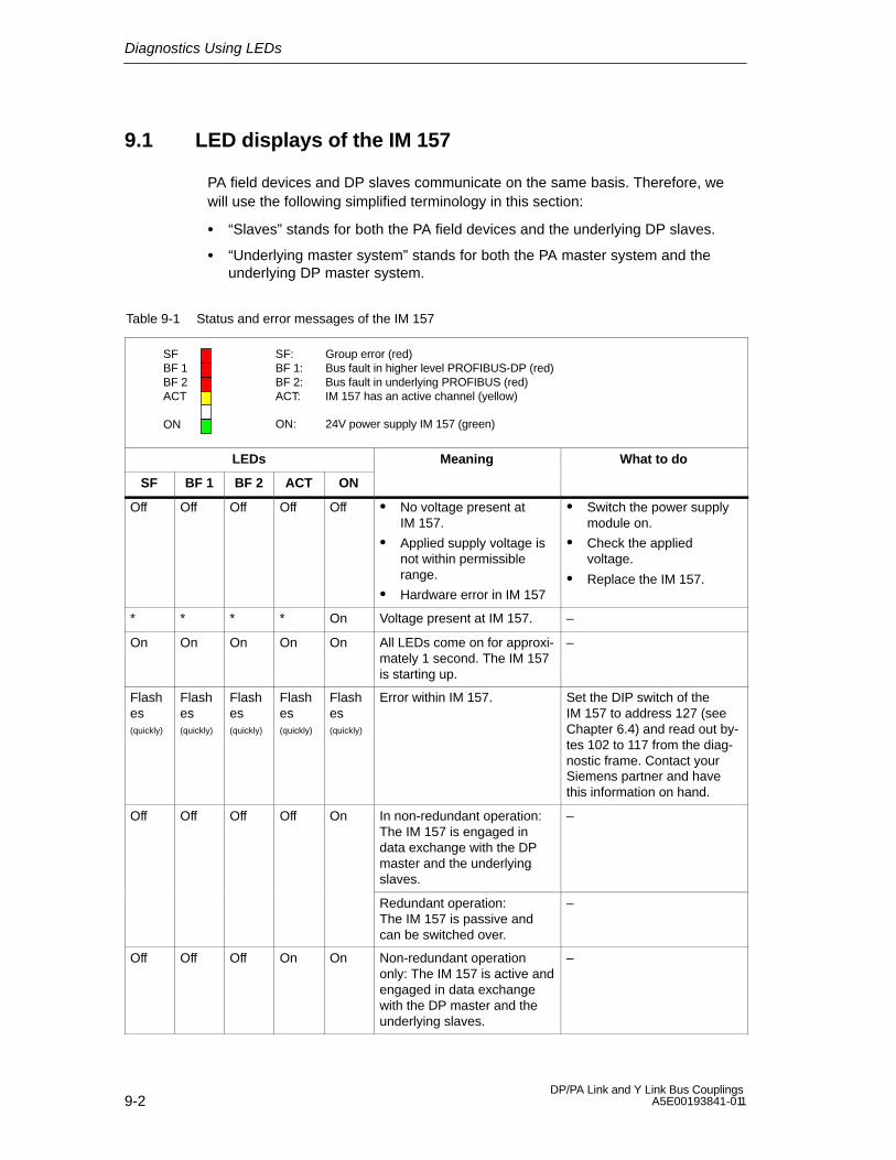
Diagnostics Using LEDs
9-2DP/PA Link and Y Link Bus Couplings
A5E00193841-011
9.1 LED displays of the IM 157
PA field devices and DP slaves communicate on the same basis. Therefore, wewill use the following simplified terminology in this section:
“Slaves” stands for both the PA field devices and the underlying DP slaves.
“Underlying master system” stands for both the PA master system and theunderlying DP master system.
Table 9-1 Status and error messages of the IM 157
BF 1
ON
BF 2
SF: Group error (red)BF 1: Bus fault in higher level PROFIBUS-DP (red)BF 2: Bus fault in underlying PROFIBUS (red)ACT: IM 157 has an active channel (yellow)
ON: 24V power supply IM 157 (green)
SF
ACT
LEDs Meaning What to do
SF BF 1 BF 2 ACT ON
Off Off Off Off Off No voltage present atIM 157.
Applied supply voltage isnot within permissiblerange.
Hardware error in IM 157
Switch the power supplymodule on.
Check the appliedvoltage.
Replace the IM 157.
* * * * On Voltage present at IM 157. –
On On On On On All LEDs come on for approxi-mately 1 second. The IM 157is starting up.
–
Flashes(quickly)
Flashes(quickly)
Flashes(quickly)
Flashes(quickly)
Flashes(quickly)
Error within IM 157. Set the DIP switch of theIM 157 to address 127 (seeChapter 6.4) and read out by-tes 102 to 117 from the diag-nostic frame. Contact yourSiemens partner and havethis information on hand.
Off Off Off Off On In non-redundant operation:The IM 157 is engaged indata exchange with the DPmaster and the underlyingslaves.
–
Redundant operation:The IM 157 is passive andcan be switched over.
–
Off Off Off On On Non-redundant operationonly: The IM 157 is active andengaged in data exchangewith the DP master and theunderlying slaves.
–
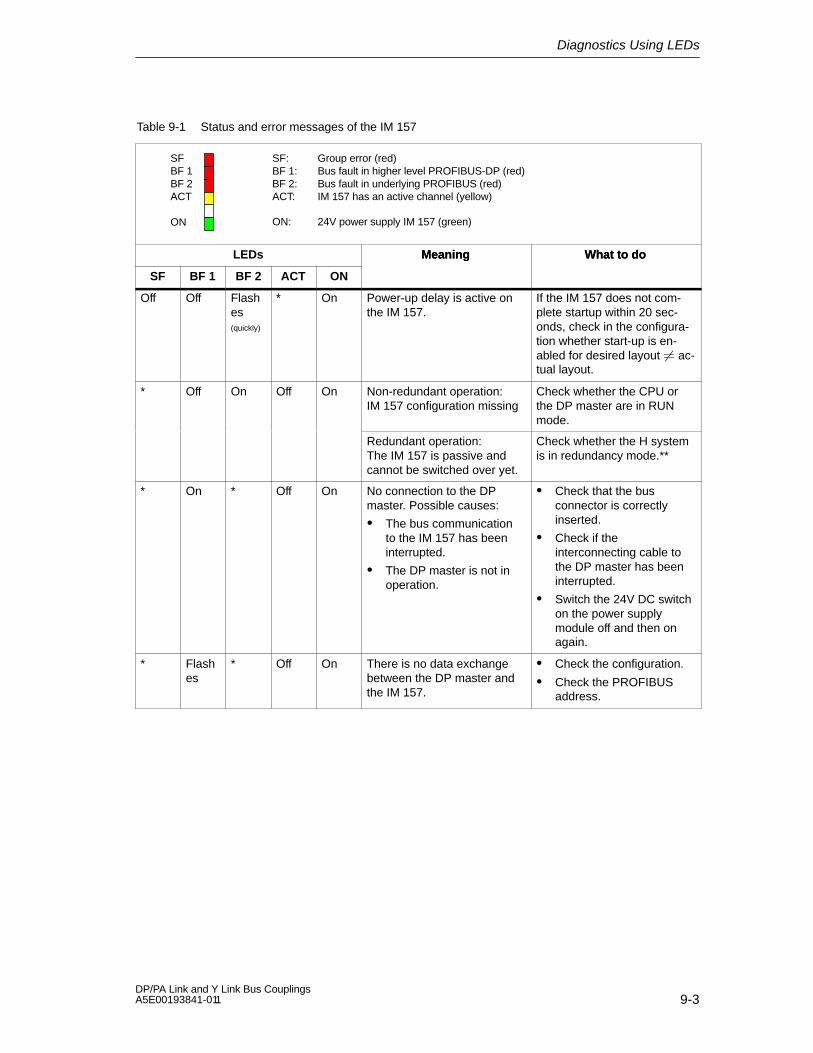
Diagnostics Using LEDs
9-3DP/PA Link and Y Link Bus Couplings A5E00193841-011
Table 9-1 Status and error messages of the IM 157
BF 1
ON
BF 2
SF: Group error (red)BF 1: Bus fault in higher level PROFIBUS-DP (red)BF 2: Bus fault in underlying PROFIBUS (red)ACT: IM 157 has an active channel (yellow)
ON: 24V power supply IM 157 (green)
SF
ACT
LEDs What to doMeaning
SF
What to doMeaning
ONACTBF 2BF 1
Off Off Flashes(quickly)
* On Power-up delay is active onthe IM 157.
If the IM 157 does not com-plete startup within 20 sec-onds, check in the configura-tion whether start-up is en-abled for desired layout ac-tual layout.
* Off On Off On Non-redundant operation:IM 157 configuration missing
Check whether the CPU orthe DP master are in RUNmode.
Redundant operation:The IM 157 is passive andcannot be switched over yet.
Check whether the H systemis in redundancy mode.**
* On * Off On No connection to the DPmaster. Possible causes:
The bus communicationto the IM 157 has beeninterrupted.
The DP master is not inoperation.
Check that the busconnector is correctlyinserted.
Check if theinterconnecting cable tothe DP master has beeninterrupted.
Switch the 24V DC switchon the power supplymodule off and then onagain.
* Flashes
* Off On There is no data exchangebetween the DP master andthe IM 157.
Check the configuration.
Check the PROFIBUSaddress.
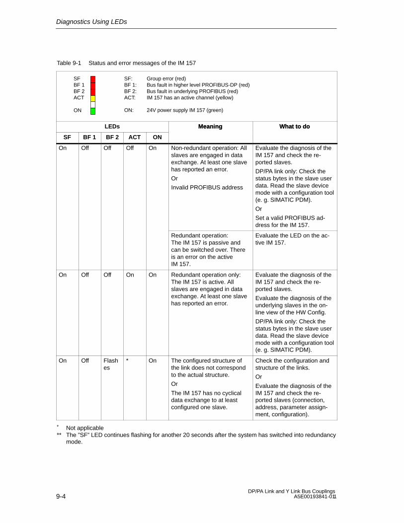
Diagnostics Using LEDs
9-4DP/PA Link and Y Link Bus Couplings
A5E00193841-011
Table 9-1 Status and error messages of the IM 157
BF 1
ON
BF 2
SF: Group error (red)BF 1: Bus fault in higher level PROFIBUS-DP (red)BF 2: Bus fault in underlying PROFIBUS (red)ACT: IM 157 has an active channel (yellow)
ON: 24V power supply IM 157 (green)
SF
ACT
LEDs What to doMeaning
SF
What to doMeaning
ONACTBF 2BF 1
On Off Off Off On Non-redundant operation: Allslaves are engaged in dataexchange. At least one slavehas reported an error.
Or
Invalid PROFIBUS address
Evaluate the diagnosis of theIM 157 and check the re-ported slaves.
DP/PA link only: Check thestatus bytes in the slave userdata. Read the slave devicemode with a configuration tool(e. g. SIMATIC PDM).
Or
Set a valid PROFIBUS ad-dress for the IM 157.
Redundant operation:The IM 157 is passive andcan be switched over. Thereis an error on the activeIM 157.
Evaluate the LED on the ac-tive IM 157.
On Off Off On On Redundant operation only:The IM 157 is active. Allslaves are engaged in dataexchange. At least one slavehas reported an error.
Evaluate the diagnosis of theIM 157 and check the re-ported slaves.
Evaluate the diagnosis of theunderlying slaves in the on-line view of the HW Config.
DP/PA link only: Check thestatus bytes in the slave userdata. Read the slave devicemode with a configuration tool(e. g. SIMATIC PDM).
On Off Flashes
* On The configured structure ofthe link does not correspondto the actual structure.
Or
The IM 157 has no cyclicaldata exchange to at leastconfigured one slave.
Check the configuration andstructure of the links.
Or
Evaluate the diagnosis of theIM 157 and check the re-ported slaves (connection,address, parameter assign-ment, configuration).
* Not applicable** The ”SF” LED continues flashing for another 20 seconds after the system has switched into redundancy
mode.

Diagnostics Using LEDs
9-5DP/PA Link and Y Link Bus Couplings A5E00193841-011
9.2 LED displays of the DP/PA coupler
Table 9-2 Status and error messages of the DP/PA coupler
DP
ON
PADP: PROFIBUS-DP bus monitoring (yellow)PA: PROFIBUS-PA bus monitoring (yellow)
ON: 24V power supply DP/PA coupler (green)
LEDs Meaning What to do
DP PA ON
* * On Power is supplied to the DP/PA coupler.The DP/PA coupler is ready foroperation.
–
* * Off Voltage not present at DP/PA coupler,
Or
Error in the DP/PA coupler.
Check the 24V power supply to theDP/PA coupler,
Or
Get in touch with your Siemens partner.
* * Flashes
PROFIBUS-PA overload Check the number of connected PAfield devices and their total current.
Flashes
* On PROFIBUS-DP frames are beingreceived.
–
Off * On PROFIBUS-DP frames are not beingreceived.
Causes:
The DP master is not in operation.
The bus cable is damaged.
The bus modules are not properlyconnected.
Connector for backplane bus isdefective.
Check whether the bus connector isproperly connected.
Check if the interconnecting cableto the DP master has beeninterrupted.
Check whether the bus modulesare properly connected.
Check the 24V power supply to theDP/PA coupler.
* Flashes
On PROFIBUS-PA frames are beingreceived.
–
* Off On PROFIBUS-PA frames are not beingreceived. For example:
The voltage on the PROFIBUS-PAis not within the permissible range(short circuit, overload).
No response from a PA field device.Possibly the PA field device is notbeing addressed.
Check the PA field devices on thePROFIBUS-PA.
Check whether the bus segmentsare properly terminated.
* Not applicable

Diagnostics Using LEDs
9-6DP/PA Link and Y Link Bus Couplings
A5E00193841-011
9.3 LED displays of the Y coupler
Table 9-3 Status messages of the Y coupler
DP 1
ONDP 2
DP 1: Bus monitoring of the internal PROFIBUS-DP (yellow)DP 2: Bus monitoring of the underlying PROFIBUS-DP (yellow)ON: 24V power supply for Y coupler (green)
LEDs Meaning What to do
BF 1 BF 2 ON
Off Off Off No voltage present at Y coupler. Switch on the IM 157 power supply.
If the ON LED does not light up whenthe IM 157 power supply is switchedon: Replace the IM 157 due to a faultyinternal power supply.
Off Off On Voltage at Y coupler. The Y coupler isready for operation. There is no dataexchange between the internal andunderlying DP master system.
Check whether the bus connectoris properly connected.
Check if the bus cable to theunderlying DP master system hasbeen interrupted.
Check whether the bus modulesare properly connected.
On Off On Frames from the underlying DPmaster system are not being received,e. g.:
The connection to the underlyingDP master system is interrupted.
DP slaves are not responding.
Check whether the underlying DPmaster system is properlyconnected (the bus connector isattached and the two busterminating resistors areconnected in if necessary).
Check the connected DP slaves.
* On On Data is being exchanged between the –
On * Oninternal and underlying DP mastersystems (at a high transmission rate).
* Flashes
On Data is being exchanged between theinternal and underlying DP master
–
Flashes
*systems (at a low transmission rate).
* Not applicable

10-1DP/PA Link and Y Link Bus Couplings A5E00193841-011
Diagnostics Using the User Program
Overview of contents
This chapter describes the structure of the IM 157 diagnosis. An example is usedto illustrate the evaluation of a diagnostic frame.
Section Topic Page
10.1 Structure of the slave diagnosis 10-2
10.2 Structure of the diagnostic blocks 10-4
10.3 Reading out the diagnosis from the underlying slaves 10-17
10.4 Example of a diagnosis in redundant operation 10-18
Some of the following details apply to both the DP/PA link with its PA field devicesand to the Y link with its underlying DP slaves. In these instances, the followingterminology will be used in the interest of clarity:
“Link” stands for both the DP/PA link and the Y link.
“Slaves” stands for both the PA field devices and the underlying DP slaves.
“Underlying master system” stands for both the PA master system and theunderlying DP master system.
Slave diagnosis
Slave diagnosis is performed in accordance with IEC 61784-1:2002 Ed1 CP 3/1.Depending on the DP master, it can be read out with STEP 7, SIMATIC PDM orother configuration tools.
In STEP 7, the diagnostic frames of the underlying DP slaves can be displayed inthe online view of the HW Config. See “Diagnosing hardware” in the STEP 7 onlinehelp.
Additional methods of reading out diagnostic information are described in theSIMATIC Software; Programming with STEP 7 V5.x manual.
10
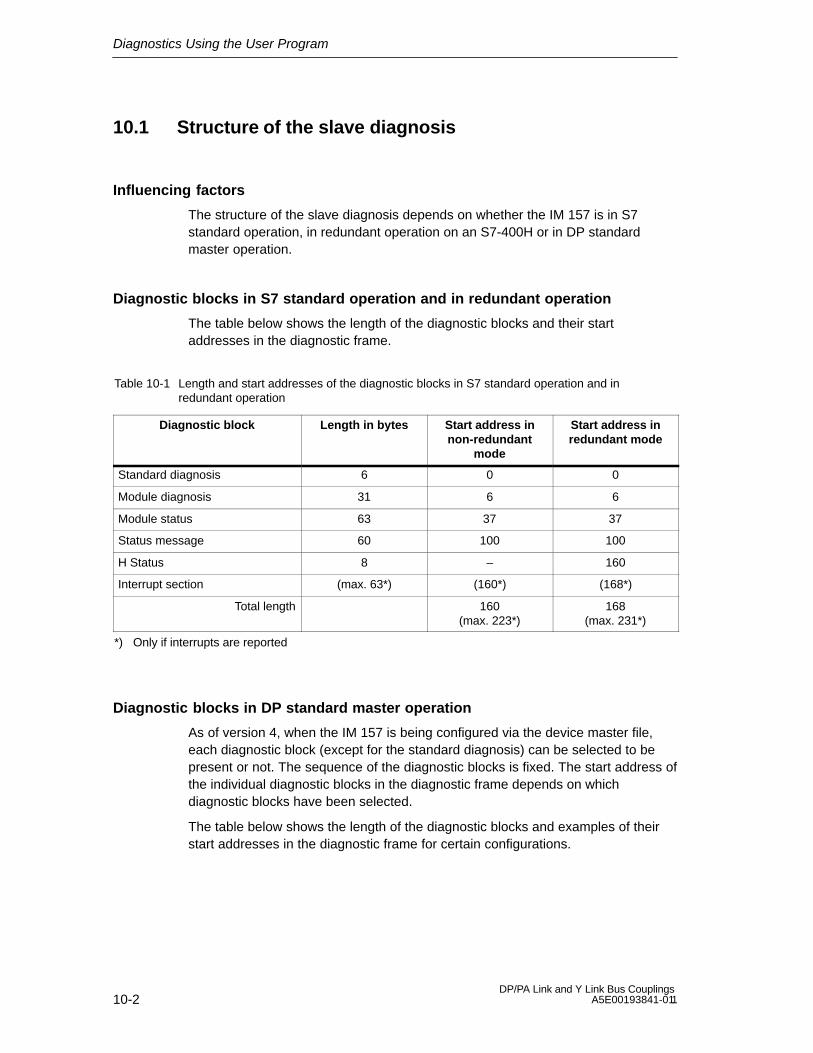
Diagnostics Using the User Program
10-2DP/PA Link and Y Link Bus Couplings
A5E00193841-011
10.1 Structure of the slave diagnosis
Influencing factors
The structure of the slave diagnosis depends on whether the IM 157 is in S7standard operation, in redundant operation on an S7-400H or in DP standardmaster operation.
Diagnostic blocks in S7 standard operation and in redundant operation
The table below shows the length of the diagnostic blocks and their startaddresses in the diagnostic frame.
Table 10-1 Length and start addresses of the diagnostic blocks in S7 standard operation and inredundant operation
Diagnostic block Length in bytes Start address innon-redundant
mode
Start address inredundant mode
Standard diagnosis 6 0 0
Module diagnosis 31 6 6
Module status 63 37 37
Status message 60 100 100
H Status 8 – 160
Interrupt section (max. 63*) (160*) (168*)
Total length 160(max. 223*)
168(max. 231*)
*) Only if interrupts are reported
Diagnostic blocks in DP standard master operation
As of version 4, when the IM 157 is being configured via the device master file,each diagnostic block (except for the standard diagnosis) can be selected to bepresent or not. The sequence of the diagnostic blocks is fixed. The start address ofthe individual diagnostic blocks in the diagnostic frame depends on whichdiagnostic blocks have been selected.
The table below shows the length of the diagnostic blocks and examples of theirstart addresses in the diagnostic frame for certain configurations.
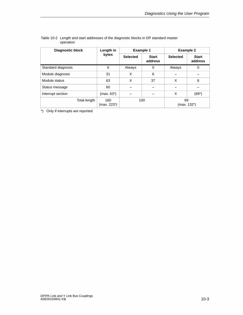
Diagnostics Using the User Program
10-3DP/PA Link and Y Link Bus Couplings A5E00193841-011
Table 10-2 Length and start addresses of the diagnostic blocks in DP standard masteroperation
Diagnostic block Length in Example 1 Example 2bytes
Selected Startaddress
Selected Startaddress
Standard diagnosis 6 Always 0 Always 0
Module diagnosis 31 X 6 – –
Module status 63 X 37 X 6
Status message 60 – – – –
Interrupt section (max. 63*) – – X (69*)
Total length 160(max. 223*)
100 69 (max. 132*)
*) Only if interrupts are reported
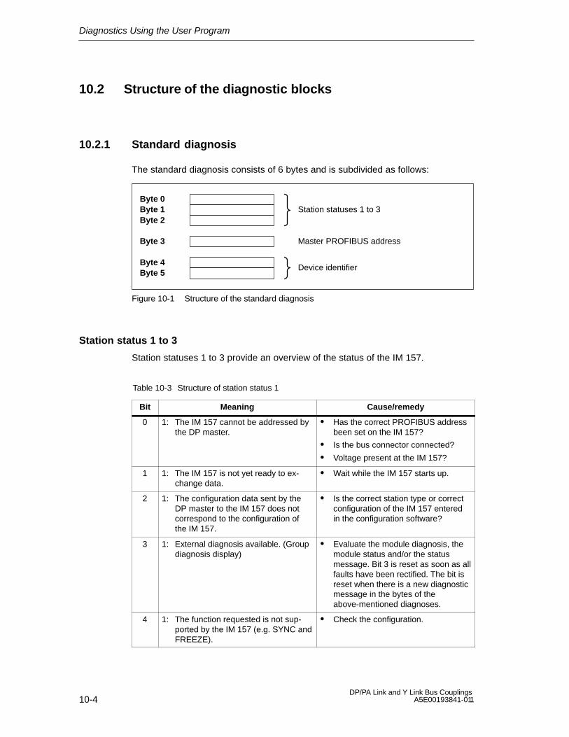
Diagnostics Using the User Program
10-4DP/PA Link and Y Link Bus Couplings
A5E00193841-011
10.2 Structure of the diagnostic blocks
10.2.1 Standard diagnosis
The standard diagnosis consists of 6 bytes and is subdivided as follows:
Byte 0Byte 1 Station statuses 1 to 3Byte 2
Byte 3
Byte 4Byte 5
Device identifier
Master PROFIBUS address
Figure 10-1 Structure of the standard diagnosis
Station status 1 to 3
Station statuses 1 to 3 provide an overview of the status of the IM 157.
Table 10-3 Structure of station status 1
Bit Meaning Cause/remedy
0 1: The IM 157 cannot be addressed bythe DP master.
Has the correct PROFIBUS addressbeen set on the IM 157?
Is the bus connector connected?
Voltage present at the IM 157?
1 1: The IM 157 is not yet ready to ex-change data.
Wait while the IM 157 starts up.
2 1: The configuration data sent by theDP master to the IM 157 does notcorrespond to the configuration ofthe IM 157.
Is the correct station type or correctconfiguration of the IM 157 enteredin the configuration software?
3 1: External diagnosis available. (Groupdiagnosis display)
Evaluate the module diagnosis, themodule status and/or the statusmessage. Bit 3 is reset as soon as allfaults have been rectified. The bit isreset when there is a new diagnosticmessage in the bytes of theabove-mentioned diagnoses.
4 1: The function requested is not sup-ported by the IM 157 (e.g. SYNC andFREEZE).
Check the configuration.

Diagnostics Using the User Program
10-5DP/PA Link and Y Link Bus Couplings A5E00193841-011
Table 10-3 Structure of station status 1, continued
Bit Cause/remedyMeaning
5 1: The DP master cannot interpret theresponse from the IM 157.
Check the bus configuration.
6 1: The configured station type does notcorrespond to the IM 157.
Is the correct station type entered inthe configuration software?
7 1: The parameters have been assignedto the IM 157 by a different DP ma-ster (not by the DP master that cur-rently has access to the IM 157).
The bit is always set to 1 when, forinstance, you are accessing theIM 157 using the programmingdevice or another DP master.
The PROFIBUS address of the DPmaster that parameterized theIM 157 is contained in the “masterPROFIBUS address” diagnosticbyte.
Table 10-4 Structure of station status 2
Bit Meaning
0 1: Parameters have to be reassigned to the IM 157.
1 0: This bit is always set to “0”.
2 1: This bit is always set to “1” when the IM 157 with this PROFIBUS address ispresent.
3 1: The response monitor has been enabled for the IM 157.
4 0: This bit is always set to “0”.
5 0: This bit is always set to “0”.
6 0: This bit is always set to “0”.
7 1: The IM 157 is disabled, i.e. it has been removed from current processing.
Table 10-5 Structure of station status 3
Bit Meaning
0 to 7 0: These bits are always set to “0”.
Master PROFIBUS address
Byte 3 of the standard diagnosis contains the PROFIBUS address of the DPmaster that parameterized the IM 157 and that has read and write access to theIM 157.
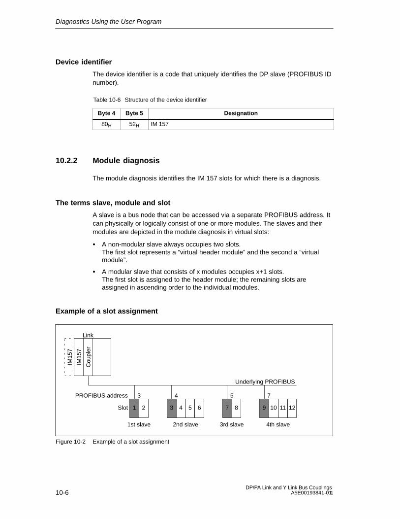
Diagnostics Using the User Program
10-6DP/PA Link and Y Link Bus Couplings
A5E00193841-011
Device identifier
The device identifier is a code that uniquely identifies the DP slave (PROFIBUS IDnumber).
Table 10-6 Structure of the device identifier
Byte 4 Byte 5 Designation
80H 52H IM 157
10.2.2 Module diagnosis
The module diagnosis identifies the IM 157 slots for which there is a diagnosis.
The terms slave, module and slot
A slave is a bus node that can be accessed via a separate PROFIBUS address. Itcan physically or logically consist of one or more modules. The slaves and theirmodules are depicted in the module diagnosis in virtual slots:
A non-modular slave always occupies two slots.The first slot represents a “virtual header module” and the second a “virtualmodule”.
A modular slave that consists of x modules occupies x+1 slots. The first slot is assigned to the header module; the remaining slots areassigned in ascending order to the individual modules.
Example of a slot assignment
Underlying PROFIBUS
IM15
7
IM15
7
Cou
pler
Link
Slot
PROFIBUS address
1st slave
1 2
3
2nd slave
3 4
4
5 6
3rd slave
7 8
5
4th slave
9 10
7
11 12
Figure 10-2 Example of a slot assignment

Diagnostics Using the User Program
10-7DP/PA Link and Y Link Bus Couplings A5E00193841-011
Structure of the module diagnosis
The module diagnosis comprises 31 bytes.
Each slave slot occupies one bit. The slaves are arranged in ascending order bytheir PROFIBUS addresses.
A bit is set if:
the corresponding slave for the respective slot delivers a module diagnosis, or
the corresponding configured slave is not engaged in data exchange with theDP master.
Byte 6
The set bit indicates that a slave either reported a diagnosis for therespective slot or failed.
Bit no.
Length of the diagnostic blockincluding byte 6 (= 31 bytes)
Code for module diagnosis
Byte 7Byte 8
7
Byte 34Byte 35Byte 36
.
.
6 5 4 3 2 1 00 1 0 1 1 1 1 1
Bit no.7 6 5 4 3 2 1 0Slots 1 to 87 6 5 4 3 2 18
15 14 13 12 11 10 916 Slots 9 to 16..
.
...
Slots 217 to 224223 222 221 220 219 218 217224Slots 225 to 232231 230 229 228 227 226 225232Slots 233 to 236236 235 234 233
Figure 10-3 Structure of the module diagnosis

Diagnostics Using the User Program
10-8DP/PA Link and Y Link Bus Couplings
A5E00193841-011
10.2.3 Module status
The module status is part of the station diagnosis and indicates the status of theconfigured modules.
Structure of the module status
The module status consists of 63 bytes.
In the module status, the status is encoded by means of two bits for each slot (seeSection 10.2.2).
The following applies to the entry in the module status:
If an underlying slave delivers its own module status in its diagnosis, this statusis copied to the appropriate location.
If an underlying slave delivers a module diagnosis but not the module status,the status 01B ”Module fault” is entered for a faulty identifier.
If an underlying slave delivers neither its own module status nor a modulediagnosis, the status is entered as follows:
– For error-free operation: 00B ”Module OK”
– For configuration error: 10B ”Incorrect module”
– For missing slave: 11B ”No module”
– For all other errors (e.g. “Prm_Fault”): 01B ”Module faulty”

Diagnostics Using the User Program
10-9DP/PA Link and Y Link Bus Couplings A5E00193841-011
Byte x
The status is encoded by means of two bits for each slot.
00B: “Module OK”, valid user data01B: “Module faulty”, user data invalid10B: “Incorrect module”, user data invalid11B: “No module”, user data invalid
Slot 1 is assigned to the first configured slave.
Bit no.
Length of the diagnostic blockincluding byte x(= 63 bytes)
Code for station diagnosis
Byte x+4Byte x+5
7
Byte x+59Byte x+60Byte x+61
.
.
.
6 5 4 3 2 1 00 0 1 1 1 1 1 1
Byte x+1 82H Status type: module statusByte x+2 Not applicableByte x+3 Not applicable
Bit no.7 6 5 4 3 2 1 04 3 2 1 Modules 1 to 48 7 6 5 Modules 5 to 8...
.
.
.
.
.
.
224 223 222 221 Modules 221 to 224
Byte x+62
228 227 226 225 Modules 225 to 228232 231 230 229 Modules 229 to 232236 235 234 233 Modules 233 to 236
Figure 10-4 Structure of the module status
Start address x is 37 for both S7 standard operation and redundant operation; inDP standard master operation, it is dependent on which diagnostic blocks arepresent (see Table 10-2).
10.2.4 Status message
The status message is part of the station diagnosis and delivers the followinginformation:
Underlying slaves that have reported diagnosis
Underlying slaves that are engaged in data exchange
State of the IM 157 as master of the underlying PROFIBUS

Diagnostics Using the User Program
10-10DP/PA Link and Y Link Bus Couplings
A5E00193841-011
Structure of the status message
The status message consists of 60 bytes.
Byte xBit no.
Length of the diagnostic blockincluding byte x(= 60 bytes)
Code for station diagnosis
7 6 5 4 3 2 1 00 0 1 1 1 1 0 0
Byte x+1 81H Status type: status messageByte x+2 Not applicableByte x+3 Not applicable
If the bit is set, this indicates that the slave with the corresponding addressreported a diagnosis.
Byte x+4
Byte x+18
.
.
Bit no.7 6 5 4 3 2 1 0Addresses 3 to 7
.
...
.
.
Addresses 112 to 119
7 6 5 4 3 – – –
Slaves that have reported diagnosis
119 118 117 116 115 114 113 112
If the bit is set, this indicates that the slave with the corresponding addressis engaged in data exchange with the IM 157.
Byte x+20
Byte x+35
.
.
Slaves that are engaged in data exchange with the IM 157
Continued overleaf
Byte x+5 Addresses 8 to 15
Byte x+19 Addresses 120 to 125– – 125 124 123 122 121 120
15 14 13 12 11 10 9 8
Bit no.7 6 5 4 3 2 1 0Addresses 3 to 7
.
...
.
.
Addresses 112 to 119
7 6 5 4 3 – – –
119 118 117 116 115 114 113 112
Addresses 8 to 15
Addresses 120 to 125– – 125 124 123 122 121 120
15 14 13 12 11 10 9 8Byte x+21
Byte x+34
Figure 10-5 Structure of the status message
Start address x is 100 for both S7 standard operation and redundant operation; inDP standard master operation, it is dependent on which diagnostic blocks arepresent (see Table 10-2).

Diagnostics Using the User Program
10-11DP/PA Link and Y Link Bus Couplings A5E00193841-011
Byte x+3682H
Continued from the previous page
Status of the IM 157
Status of the IM 157, see table belowByte x+37 Identifier for the configured order number
(BCD-coded)Byte x+38 ReservedByte x+39 ReservedByte x+40 ReservedByte x+41 IM 157 hardware versionByte x+42 IM 157 firmware version
Byte x+43Bit no.
1: Start-up delay enabled
7 6 5 4 3 2 1 00 0 0
0: At least one slave not is engaged in data exchangewith the IM 157.
1: All slaves are engaged in data exchange with theIM 157
1: Missing or incorrect configuration1: Invalid bus parameter for PROFIBUS-DP
Overview of channel diagnosis
Byte x+44Byte x+45
Byte x+58Byte x+59
.
.
If a bit is set, this indicates that the slave with the corresponding addressreported a channel-related diagnosis.
0
Bit no.7 6 5 4 3 2 1 0Addresses 3 to 7
.
...
.
.
Addresses 112 to 119
7 6 5 4 3 – – –
119 118 117 116 115 114 113 112
Addresses 8 to 15
Addresses 120 to 125– – 125 124 123 122 121 120
15 14 13 12 11 10 9 8
Figure 10-6 Structure of the status message, continued

Diagnostics Using the User Program
10-12DP/PA Link and Y Link Bus Couplings
A5E00193841-011
Table 10-7 Meaning of byte x+36 in the status message
Byte x+36 Status Meaning
00H OFF There is no data exchange between the IM 157 and theunderlying slaves. The IM 157 can neither receive nor forwardthe token.
40H STOP There is no data exchange between the IM 157 and theunderlying slaves. The IM 157 can receive and forward thetoken
80H CLEAR The IM 157 reads the input data cyclically. Output data arekept in a safe status or are set to ”0”. The IM 157 can receiveand forward the token.
C0H RUN (OPERATE)
The IM 157 reads the input data of the slaves cyclically andforwards the output data to the slaves. The IM 157 canreceive and forward the token.
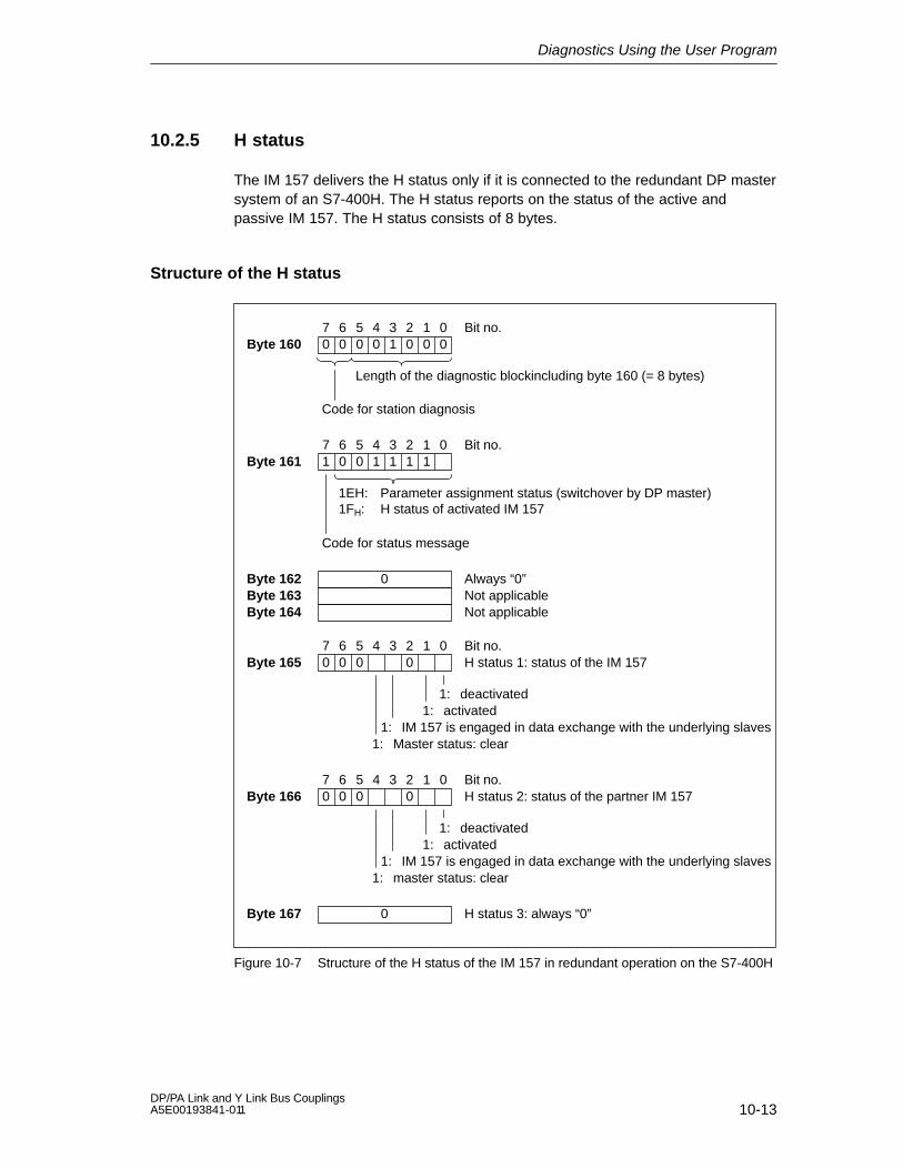
Diagnostics Using the User Program
10-13DP/PA Link and Y Link Bus Couplings A5E00193841-011
10.2.5 H status
The IM 157 delivers the H status only if it is connected to the redundant DP mastersystem of an S7-400H. The H status reports on the status of the active andpassive IM 157. The H status consists of 8 bytes.
Structure of the H status
Byte 160Bit no.
Length of the diagnostic blockincluding byte 160 (= 8 bytes)
Code for station diagnosis
7 6 5 4 3 2 1 00 0 0 0 1 0 0 0
1EH: Parameter assignment status (switchover by DP master)1FH: H status of activated IM 157
Code for status message
7 6 5 4 3 2 1 01 0 0 1 1 1 1Byte 161
Bit no.
Byte 162 0 Always “0”Byte 163 Not applicableByte 164 Not applicable
7 6 5 4 3 2 1 00 0 0 0Byte 165
Bit no.H status 1: status of the IM 157
1: deactivated1: activated
1: IM 157 is engaged in data exchange with the underlying slaves1: Master status: clear
7 6 5 4 3 2 1 00 0 0 0Byte 166
Bit no.H status 2: status of the partner IM 157
1: deactivated1: activated
1: IM 157 is engaged in data exchange with the underlying slaves1: master status: clear
Byte 167 0 H status 3: always “0”
Figure 10-7 Structure of the H status of the IM 157 in redundant operation on the S7-400H

Diagnostics Using the User Program
10-14DP/PA Link and Y Link Bus Couplings
A5E00193841-011
10.2.6 Interrupts
The interrupt section provides information on the interrupt type and the event thattriggered the interrupt. The interrupt section is only transmitted if an interrupt ispresent
Structure of the interrupt section
The structure of the interrupt section depends on which DP master the IM 157 isbeing operated on:
On a DPV1-capable DP master, the interrupt section consists of a maximum of63 bytes.
On a redundant S7 master not capable of DPV1, the interrupt section consistsof 20 bytes.
Structure of the interrupt section on the redundant S7 master that is not capableof DPV1
Byte 168Bit no.
Length of the diagnostic blockincluding byte 168 (= 20 bytes)
Code for station diagnosis
7 6 5 4 3 2 1 00 0 0 1 0 1 0 0
Byte 169 01H Interrupt type: diagnostic interruptByte 170 Slot number of the IM 157Byte 171 01H: incoming error
02H: outgoing error
Byte 187
.
.
Byte 174
02H
Byte 172 00H: no fault05H: module fault (error detected on underlying
master system)Byte 173 0BH Reserved
00H
00H
.
. Reserved
Figure 10-8 Structure of the interrupt section on the redundant S7 master that is not
capable of DPV1

Diagnostics Using the User Program
10-15DP/PA Link and Y Link Bus Couplings A5E00193841-011
Structure of the interrupt section on the DPV1-capable DP master
The interrupt section consists of an interrupt header and the additional interruptfunction. The interrupt header always consists of four bytes. The structure of theadditional interrupt function depends on the interrupt type. Its length is a maximumof 59 bytes.
Byte xBit no.
Length of the diagnostic blockincluding byte x(max. 63 bytes)
Code for station diagnosis
7 6 5 4 3 2 1 00 0
Byte x+1 0 Interrupt type, see table belowByte x+2 Slot number of the IM 157Byte x+3
00B: no differentiation between incoming and outgoinginterrupt
01B: incoming interrupt10B: outgoing interrupt11B: outgoing interrupt, slot still faulty
02H
Bit no.7 6 5 4 3 2 1 0
1: User acknowledge requiredInterrupt sequence number
The remaining structure and the length of the interrupt section depend on the interrupttype.
Figure 10-9 Structure of the interrupt header on the DPV1-capable DP master
Start address x is 168 in redundant operation and 160 in DP standard masteroperation.
Interrupt type
Table 10-8 Interrupt m type (byte x+1 in interrupt section)
Byte x+1 Interrupt type Byte x+1 Interrupt type
00H Reserved 05H Status interrupt *)
01H Diagnostic interrupt 06H Update interrupt *)
02H Process interrupt *) 07H to 1FH Reserved
03H Removal interrupt 20H to 7EH Manufacturer-specificinterrupt *)
04H Insertion interrupt 7FH Reserved
*) These interrupt types only occur if they are generated by an underlying DPV1 slave andpassed on by the IM 157 (interrupt routing, see below).

Diagnostics Using the User Program
10-16DP/PA Link and Y Link Bus Couplings
A5E00193841-011
Diagnostic interrupt
When a DPV0 slave or a DPV1 slave not capable of interrupts reports a diagnosison the underlying master system, the IM 157 initiates a diagnosis interrupt on thehigher level DP master system (”proxy diagnosis interrupt”).
The diagnostic frame of the slave is stored in the additional interrupt information. Ifthis frame is longer than 59 bytes, the information beginning with the 60th byte isdiscarded. In addition, bit 7 (Ext_Diag_Overflow) is set in the third passed byte(byte x+6).
The diagnosis of an interrupt-capable DPV1 slave that is operated in the DPV1mode does not lead to a diagnostic interrupt.
Insertion/removal interrupt
If a slave fails or is restored on the underlying master system, the IM 157 initiatesan insertion or removal interrupt on the higher level DP master system.
Byte x+4 Bus address of the slave concernedByte x+5 Number of identifiers of the slave concerned on
the underlying master system
Byte x+6 Offset of the input data of the slave concerned inthe input data of the IM 157
Byte x+7 Length of the input data of the slave concerned inbytes
Figure 10-10 Structure of the additional interrupt information for the insertion/removal
interrupt
Start address x is 168 in redundant operation and 160 in DP standard masteroperation.
For modular slaves, the additional interrupt information refers to the entire slaveand not to the individual modules.
Insertion/removal interrupts are not reported until after the start-up delay haselapsed. Removal interrupts that occur before that point are processed later,whereas insertion interrupts are discarded.

Diagnostics Using the User Program
10-17DP/PA Link and Y Link Bus Couplings A5E00193841-011
Interrupt routing
If an interrupt-capable DPV1 slave initiates an interrupt on the underlying mastersystem, the interrupt is passed on to the higher level DP master system by theIM 157.
The interrupt header and additional interrupt information of the slave are stored inthe interrupt section of the IM 157. With the exception of slot number andsequence number, this information remains unchanged.
10.3 Reading out the diagnosis from the underlying slaves
The diagnostic data of underlying slaves capable of diagnostics that is buffered inthe IM 157 can be read out via the SFC 59 ”RD_REC”.
Prerequisites
The link must be operated on a DPV1 master.
Parameters for SFC 59 ”RD_REC”
The table below shows the required values for the call parameters of the SFC 59”RD_REC”.
Table 10-9 Call parameters for SFC 59 ”RD_REC”
Parameters Value, meaning
IOID B#16#54 (I/O input PE)
LADDR Diagnostic address of the IM 157 from the HW Config
RECNUM Node number of the slave whose diagnosis is to be read
The error information that may be found in the RET_VAL return value are listed inTable 8-5.
Diagnostics Using the User Program
10-18DP/PA Link and Y Link Bus Couplings
A5E00193841-011
10.4 Example of a diagnosis in redundant operation
Introduction
This example shows the call of a typical diagnosis of the active IM 157 inredundant operation.
10.4.1 Task
The following assumptions have been made for this example:
Both IM 157 have the diagnostic address 3FEH.
The underlying PROFIBUS master system consists of 4 configured slaves
Slaves have the addresses 4, 8, 12 and 20
Configuration of the slaves:
– Slave 4 is a non-modular slave
– Slave 8 consists of one header module and 6 modules
– Slave 12 consists of one header module and 2 modules
– Slave 20 consists of one header module and 3 modules
All configured slaves are engaged in data exchange with the active IM 157.
Slave 8 reports a diagnosis:
– Modules 1 and 3 report diagnoses
– Module 1 reports a limit violation
– Module 3 reports an incorrect configuration
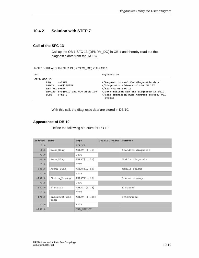
Diagnostics Using the User Program
10-19DP/PA Link and Y Link Bus Couplings A5E00193841-011
10.4.2 Solution with STEP 7
Call of the SFC 13
Call up the OB 1 SFC 13 (DPNRM_DG) in OB 1 and thereby read out thediagnostic data from the IM 157.
Table 10-10Call of the SFC 13 (DPNRM_DG) in the OB 1
STL Explanation
CALL SFC 13REQ :=TRUELADDR :=W#16#3FERET_VAL :=MW0RECORD :=P#DB10.DBX 0.0 BYTE 190BUSY :=M2.0
//Request to read the diagnostic data//Diagnostic address of the IM 157//RET_VAL of SFC 13//Data mailbox for the diagnosis in DB10//Read operation runs through several OB1
cycles
With this call, the diagnostic data are stored in DB 10.
Appearance of DB 10
Define the following structure for DB 10:
Address Name Type Initial value Comment
0.0 STRUCT
+0.0 Norm_Diag ARRAY [1..6] Standard diagnosis
*1.0 BYTE
+6.0 Kenn_Diag ARRAY[1..31] Module diagnosis
*1.0 BYTE
+38.0 Modul_Diag ARRAY[1..63] Module status
*1.0 BYTE
+102.0 Status_Message ARRAY[1..60] Status message
*1.0 BYTE
+162.0 H_Status ARRAY [1..8] H Status
*1.0 BYTE
+170.0 Interrupt sec-tion
ARRAY [1..20] Interrupts
*1.0 BYTE
=190.0 END_STRUCT

Diagnostics Using the User Program
10-20DP/PA Link and Y Link Bus Couplings
A5E00193841-011
10.4.3 Evaluation of the diagnostic data
The relevant diagnostic data in DB 10 have the following meanings:
7 Bit no.6 5 4 13 2 0DB10.DBB41:
Slave 4; slot 1: slave OK
Slave 4; slot 2: module OK
DB10.DBB42:Slave 8; slot 3: module OK
00 001 110
00 010 000
What is the status of the configured slots (modules)?
Slave 8; slot 1: slave faulty
Slave 8; slot 2: module faulty
Slave 8; slot 4: incorrect module
Slave 8; slot 5: module OK
Slave 8; slot 6: module OK
7 Bit no.6 5 4 13 2 0DB10.DBB43:
Slave 8; slot 7: module OK
Slave 12; slot 1: slave OK
DB10.DBB44:Slave 20; slot 1: slave OK
00 000 000
00 000 000
Slave 12; slot 2: module OK
Slave 12; slot 3: module OK
Slave 20; slot 2: module OK
7 Bit no.6 5 4 13 2 0DB10.DBB7:
Slave 8 occupies 7 slots;in this case, header module and modules 1 to 5; module 1 and 3 report diagnosis
DB10.DBB8:Slave 8: module 6
01 011 000
00 000 000
Module diagnosis (overview of the slots of slaves with a diagnosis)
Slave 4 occupies 2 slots
Slave 12 occupies 3 slots
Slave 20 occupies 4 slots
Slave 20; slot 3: module OK
Slave 20; slot 4: module OK

Diagnostics Using the User Program
10-21DP/PA Link and Y Link Bus Couplings A5E00193841-011
7 Bit no.6 5 4 13 2 0DB10.DBB105:
Slave 8 has reported a diagnosis
Reading out the diagnosis of the underlyingslave, seeSection 10.3
DB10.DBB120:
Slave 4 is engaged in data exchange with IM 157
10 000 000
00 000 100
Which slaves are reporting a diagnosis?
DB10.DBB121:
Slave 8 is engaged in data exchange with IM 157
10 000 100
DB10.DBB122:
Slave 20 is engaged in data exchange with IM 157
00 000 100
Slave 12 is engaged in data exchange with IM 157
DB10.DBB136: 00 000 001DB10.DBB137: 00 100 001DB10.DBB138: 00 000 000DB10.DBB139: 00 000 000DB10.DBB140: 00 000 000DB10.DBB141: 00 001 100DB10.DBB142: 00 000 010
The IM 157 (DP master) is in RUN (OPERATE) modeIdentifier for the configured order number 82BCD
ReservedReservedIM 157 hardware version
IM 157 firmware version
Which configured slaves are involved in data exchange with the DP master?
What status does the DP master have?
What status does the underlying DP master system have?
DB10.DBB143:
Power-up of PROFIBUS-DP is completed.
00 100 000
All slaves are engaged in data exchange with theIM 157
Which slaves are reporting a channel-related diagnosis?
Reserved
7 Bit no.6 5 4 13 2 0DB10.DBB145:
Slave 8 has reported a channel-related diagnosis
10 000 000

Diagnostics Using the User Program
10-22DP/PA Link and Y Link Bus Couplings
A5E00193841-011
7 Bit no.6 5 4 13 2 0DB10.DBB161: Identifier: H status of the link
DB10.DBB165:
001
00 110 000
Which status do the two IM 157 modules have?
IM 157 activated
IM 157 involved in data exchange
1 111 1
7 0
Status of the relevant IM 157
DB10.DBB166: 10 010 000
IM 157 disabled (stand-by mode)
IM 157 involved in data exchange
7 0
Status of the partner IM 157
The SIMATIC H station always reads only the active IM 157. Therefore, changingthe active channel has no effect on the H status.

A-1DP/PA Link and Y Link Bus Couplings A5E00193841-011
Fundamentals of PROFIBUS-PA
PROFIBUS-PA
PROFIBUS-PA is the PROFIBUS for Process Automation (PA) and is based onIEC 61784-1:2002 Ed1 CP 3/2 with regard to transmission technology and protocoland on the PA profile.
PROFIBUS-PA = PROFIBUS-DP communication protocol
+
Synchronous transmission technology
Any field device that is suitable for the PROFIBUS-PA can be connected to theDP/PA link bus connection.
Measuring transducers, valves, actuators, etc.
Networked by a serial bus system
For use in chemical and process engineering
With field device supply via the data line
Also for explosion-proof applications (EEx [ia] ignition protection)
Chapter overview
Section Topic Page
A.1 Intrinsic safety A-2
A.2 Field device supply via PROFIBUS-PA A-3
A.3 Extending PROFIBUS-PA with the DP/PA link coupler A-4
A.4 Partyline and Star-type topology A-5
A

Fundamentals of PROFIBUS-PA
A-2DP/PA Link and Y Link Bus Couplings
A5E00193841-011
A.1 Intrinsic safety
Intrinsic safety
The intrinsic safety type of ignition protection is based on the fact that a certainminimum ignition energy is required to ignite an explosive atmosphere. In anintrinsically safe electric circuit, this minimum ignition energy does not exist in theexplosion-proof area either during normal operation or in the event of amalfunction. The intrinsic safety of a circuit is achieved by limiting the current andvoltage in order to prevent sparking and high temperatures as possible ignitionsources. The intrinsic safety type of ignition protection is thus limited to circuits withrelatively low performance.
Spark ignition
The so-called spark ignition is eliminated because sparks, which usually occurwhen a circuit is opened and closed either during operation or in the event of ashort circuit or ground fault, are ruled out by limiting the current and voltage andavoiding large inductivities.
Thermal ignition
Thermal ignition is not possible either during normal operation or in the event of amalfunction, since the equipment and lines in the intrinsically safe circuit cannotoverheat.
Further information
You will find further information on the subjects of intrinsic safety and explosionprotection in the following publications:
The manual entitled Automation Systems S7-300, M7-300, ET 200M Ex-I/OModules (Order no. 6ES7 398-8RA00-8xA0)
PTB report W-53, Brunswick, March 1993 (Investigations into the intrinsicsafety of field bus systems)
PROFIBUS-PA Installation guide, Information on the use of IEC 1158-2 technology for PROFIBUS, (German Art. No. 2.091, English Art. No. 2.092)PROFIBUS-Nutzerorganisation e. V., Haid-und-Neu-Straße 7, D-76131 Karlsruhe
On the Internet under
www.profibus.com

Fundamentals of PROFIBUS-PA
A-3DP/PA Link and Y Link Bus Couplings A5E00193841-011
A.2 Field device supply via PROFIBUS-PA
Operating principle
When the DP/PA link coupler is used, the field devices can be supplied via the dataline of PROFIBUS-PA.
Structure
The total current of all the field devices must not exceed the maximum outputcurrent of the DP/PA coupler. The maximum output current thus limits the numberof field devices that can be connected to PROFIBUS-PA.
PROFIBUS-DP
PROFIBUS-PA
Imax.
I1 I2 I3... ...Im
Imax 400 mA
24 VDC
Field device1
Field device2
Field device3...
Field device
...m
DP/PA coupler6ES7 157-0AC80-0XA0
PROFIBUS-DP
PROFIBUS-PA
Imax.
I1 I2 I3... ...In
24 VDC
Explosion-proof area
Field device1
Field device2
Field device3...
Field device...n
Imax 110 mA
DP/PA coupler Ex [i]6ES7 157-0AD81-0XA0
EEx [i] II C ignition protection
Figure A-1 Field device supply
Extension
You must install an additional DP/PA coupler if you exceed the maximum outputcurrent of the DP/PA coupler (see Section A.3).

Fundamentals of PROFIBUS-PA
A-4DP/PA Link and Y Link Bus Couplings
A5E00193841-011
A.3 Extending PROFIBUS-PA with the DP/PA link coupler
Extension
The figure below shows the configuration of a PROFIBUS-PA system with a DPmaster:
DP master
Max. 5 DP/PAcouplers perIM 157
Max. 64 PAfield devicesper DP/PA link
DP master
Max. 31 PA fielddevices perDP/PA coupler
Configuration with a DP/PA link Configuration with DP/PA couplers
Figure A-2 Extension of PROFIBUS-PA with a DP/PA link or DP/PA couplers
Rules
The following rules apply to PROFIBUS-PA extensions:
There can be no more than 31 PA field devices in a physical PROFIBUS-PAsegment.
Not more than one supply device (= DP/PA coupler) can be connected in onephysical PROFIBUS-PA segment.
No more than 64 PA field devices can be connected to a DP/PA link. Themaximum number of PA field devices that can be connected in each physicalPROFIBUS-PA segment and each DP/PA coupler is limited by the maximumoutput current of the DP/PA coupler and the I/O data to be transferred (seeAppendix B).

Fundamentals of PROFIBUS-PA
A-5DP/PA Link and Y Link Bus Couplings A5E00193841-011
A.4 Partyline and star-type topology
Topology
PROFIBUS-PA can have a partyline or star-type topology.
PROFIBUS-DP
PROFIBUS-PA
24 VDC
DP/PA coupler(with integratedbus terminatingelement)
Distribution box
LineT junction
Star
Main line
Spur line
Bus terminating element
Spur line
Figure A-3 Partyline and star-type topology
Network extension
For a standard PROFIBUS-PA cable (cable type A as per PNO), the maximumlength of the trunk and spur lines is as follows given maximum power consumptionfrom the DP/PA coupler:
560 m for the DP/PA coupler (6ES7 157-0AC80-0XA0)
920 m for the DP/PA coupler Ex [i] (6ES7 157-0AD81-0XA0)
Note
Longer cables are possible if the overall power consumption of the PA fielddevices is low and if they are distributed.

Fundamentals of PROFIBUS-PA
A-6DP/PA Link and Y Link Bus Couplings
A5E00193841-011
Bus terminating element for PROFIBUS-PA
To ensure trouble-free operation, the end of a PROFIBUS-PA line must have a busterminating element.
Use an RC element in series connection for the bus terminating element (R = 100 2 %; C = 1 F 20 %). For components, see Appendix D.
Spur line
The maximum permissible spur line lengths are listed in Table A-1. Note also themaximum length of the aggregate line (see above).
Table A-1 Spur line length for the DP/PA coupler
Number of spur lines Maximum length of a spur line
DP/PA coupler DP/PA coupler Ex [i]
1 to 12 Max. 120 m Max. 30 m
13 to 14 Max. 90 m Max. 30 m
15 to 18 Max. 60 m Max. 30 m
19 to 24 Max. 30 m Max. 30 m
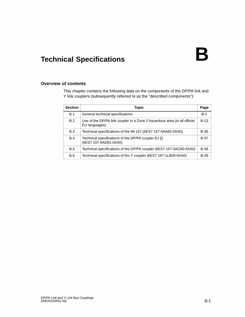
B-1DP/PA Link and Y Link Bus Couplings A5E00193841-011
Technical Specifications
Overview of contents
This chapter contains the following data on the components of the DP/PA link andY link couplers (subsequently referred to as the “described components”):
Section Topic Page
B.1 General technical specifications B-2
B.2 Use of the DP/PA link coupler in a Zone 2 hazardous area (in all officialEU languages)
B-13
B.3 Technical specifications of the IM 157 (6ES7 157-0AA82-0XA0) B-36
B.4 Technical specifications of the DP/PA coupler Ex [i](6ES7 157-0AD81-0XA0)
B-37
B.5 Technical specifications of the DP/PA coupler (6ES7 157-0AC80-0XA0) B-38
B.6 Technical specifications of the Y coupler (6ES7 197-1LB00-0XA0) B-39
B
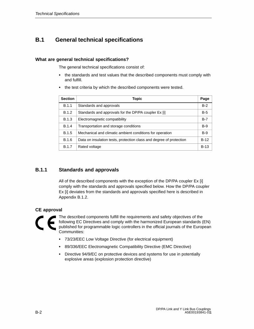
Technical Specifications
B-2DP/PA Link and Y Link Bus Couplings
A5E00193841-011
B.1 General technical specifications
What are general technical specifications?
The general technical specifications consist of:
the standards and test values that the described components must comply withand fulfill.
the test criteria by which the described components were tested.
Section Topic Page
B.1.1 Standards and approvals B-2
B.1.2 Standards and approvals for the DP/PA coupler Ex [i] B-5
B.1.3 Electromagnetic compatibility B-7
B.1.4 Transportation and storage conditions B-9
B.1.5 Mechanical and climatic ambient conditions for operation B-9
B.1.6 Data on insulation tests, protection class and degree of protection B-12
B.1.7 Rated voltage B-13
B.1.1 Standards and approvals
All of the described components with the exception of the DP/PA coupler Ex [i]comply with the standards and approvals specified below. How the DP/PA couplerEx [i] deviates from the standards and approvals specified here is described inAppendix B.1.2.
CE approval
The described components fulfill the requirements and safety objectives of thefollowing EC Directives and comply with the harmonized European standards (EN)published for programmable logic controllers in the official journals of the EuropeanCommunities:
73/23/EEC Low Voltage Directive (for electrical equipment)
89/336/EEC Electromagnetic Compatibility Directive (EMC Directive)
Directive 94/9/EC on protective devices and systems for use in potentiallyexplosive areas (explosion protection directive)

Technical Specifications
B-3DP/PA Link and Y Link Bus Couplings A5E00193841-011
ATEX approval
KEMA 02ATEX1096 Xin accordance with EN 50021:1999 (Electrical apparatus for potentiallyexplosive atmospheres; Type of protection “n”)
II 3 G EEx nA II Tx
The EC Declarations of Conformity are available for the relevant authorities at thefollowing address:
Siemens AktiengesellschaftBereich Automatisierungs- und AntriebstechnikA&D AS RD42Postfach 1963D-92209 Amberg
UL/CSA approval
Underwriters Laboratories Inc. in accordance with
Ordinary locations
UL 508 (Industrial Control Equipment)
CSA C22.2 No. 142 (Process Control Equipment)
Hazardous locations
UL 1604
CSA-213
APPOROVED for use inClass I, Division 2, Group A, B, C, D Tx;Class I, Zone 2, Group IIC Tx
Note
The approvals currently effective are found on the type label of each module.
FM approval
Factory Mutual Research (FM) in accordance with
Approval Standard Class Number 3611 (1999)
Class I, Division 2, Group A, B, C, D Tx;Class I, Zone 2, Group IIC Tx
HAZ. LOC.

Technical Specifications
B-4DP/PA Link and Y Link Bus Couplings
A5E00193841-011
!Warning
There is a risk of injury and damage to property.
In areas where there is a risk of explosion, injuries and damage may be caused ifyou remove connectors during operation.
In areas where there is a risk of explosion, always deenergize all components inorder to remove the connectors.
Certification in Australia
The described components comply with the requirements of the AS/NZS 2064 (Class A) standard.
IEC 61131
The described components comply with the requirements and criteria of the IEC61131-2 standard (programmable logic controllers, Part 2: Equipment requirementsand tests).
PROFIBUS standard
The described components are based on the standard IEC 61784-1:2002 Ed1CP 3/1.
PROFIBUS-PA
The DP/PA coupler meets the requirements and criteria of the PROFIBUS-PAdirective.
Use in industrial enrivonments
SIMATIC products are designed for use in industrial environments.
Table B-1 Use in industrial enrivonments
Area of application Requirements
Emitted interference Noise immunity
Industry EN 50081-2 : 1993 EN 50082-2 : 1995
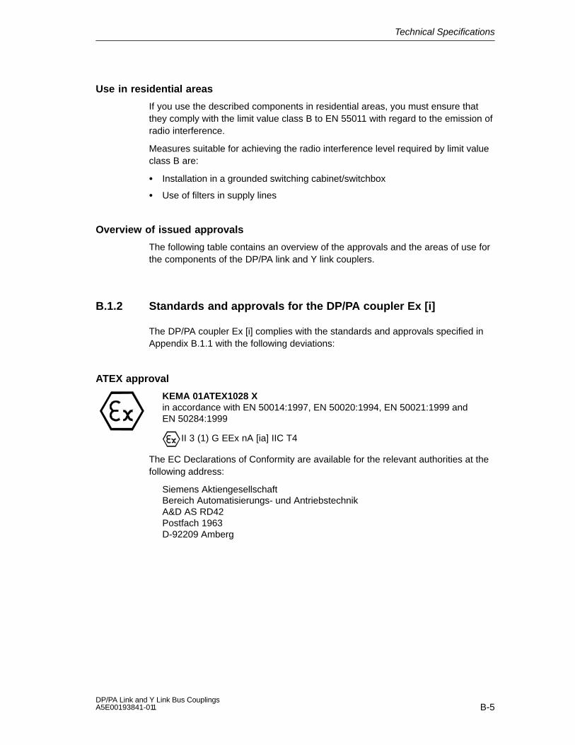
Technical Specifications
B-5DP/PA Link and Y Link Bus Couplings A5E00193841-011
Use in residential areas
If you use the described components in residential areas, you must ensure thatthey comply with the limit value class B to EN 55011 with regard to the emission ofradio interference.
Measures suitable for achieving the radio interference level required by limit valueclass B are:
Installation in a grounded switching cabinet/switchbox
Use of filters in supply lines
Overview of issued approvals
The following table contains an overview of the approvals and the areas of use forthe components of the DP/PA link and Y link couplers.
B.1.2 Standards and approvals for the DP/PA coupler Ex [i]
The DP/PA coupler Ex [i] complies with the standards and approvals specified inAppendix B.1.1 with the following deviations:
ATEX approval
KEMA 01ATEX1028 Xin accordance with EN 50014:1997, EN 50020:1994, EN 50021:1999 andEN 50284:1999
II 3 (1) G EEx nA [ia] IIC T4
The EC Declarations of Conformity are available for the relevant authorities at thefollowing address:
Siemens AktiengesellschaftBereich Automatisierungs- und AntriebstechnikA&D AS RD42Postfach 1963D-92209 Amberg
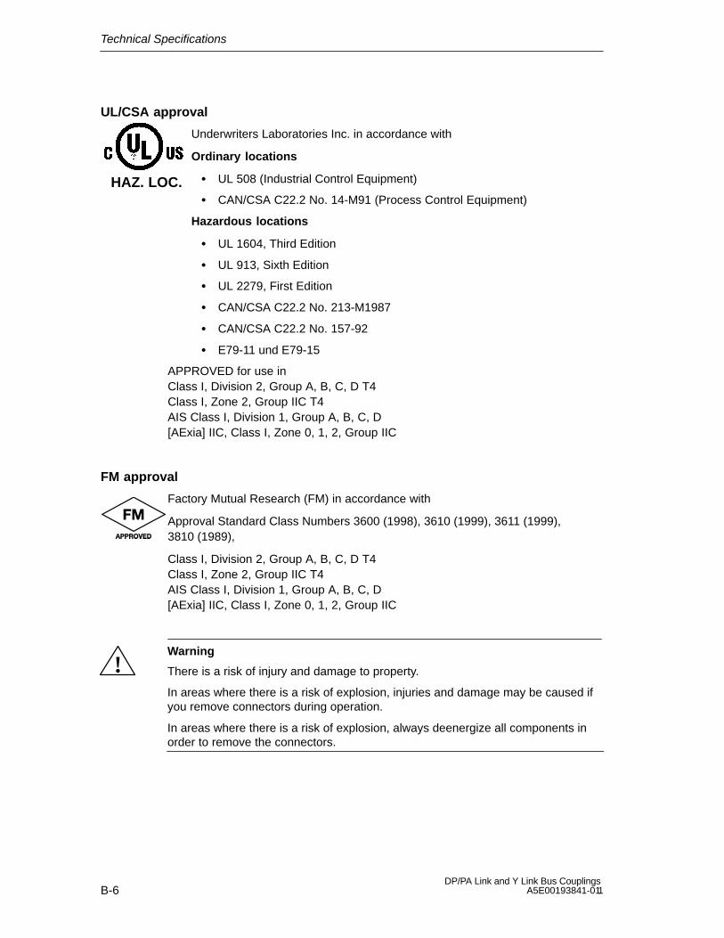
Technical Specifications
B-6DP/PA Link and Y Link Bus Couplings
A5E00193841-011
UL/CSA approval
Underwriters Laboratories Inc. in accordance with
Ordinary locations
UL 508 (Industrial Control Equipment)
CAN/CSA C22.2 No. 14-M91 (Process Control Equipment)
Hazardous locations
UL 1604, Third Edition
UL 913, Sixth Edition
UL 2279, First Edition
CAN/CSA C22.2 No. 213-M1987
CAN/CSA C22.2 No. 157-92
E79-11 und E79-15
APPROVED for use inClass I, Division 2, Group A, B, C, D T4Class I, Zone 2, Group IIC T4AIS Class I, Division 1, Group A, B, C, D[AExia] IIC, Class I, Zone 0, 1, 2, Group IIC
FM approval
Factory Mutual Research (FM) in accordance with
Approval Standard Class Numbers 3600 (1998), 3610 (1999), 3611 (1999),3810 (1989),
Class I, Division 2, Group A, B, C, D T4Class I, Zone 2, Group IIC T4AIS Class I, Division 1, Group A, B, C, D[AExia] IIC, Class I, Zone 0, 1, 2, Group IIC
!Warning
There is a risk of injury and damage to property.
In areas where there is a risk of explosion, injuries and damage may be caused ifyou remove connectors during operation.
In areas where there is a risk of explosion, always deenergize all components inorder to remove the connectors.
HAZ. LOC.

Technical Specifications
B-7DP/PA Link and Y Link Bus Couplings A5E00193841-011
B.1.3 Electromagnetic compatibility
Introduction
This chapter contains data on the interference immunity of the describedcomponents and on RFI suppression.
The described components meet the requirements of the European EMClegislation for the single market.
Definition of “EMC”
Electromagnetic compatibility (EMC) is the capacity of a piece of electricalequipment to function in a satisfactory manner in its electromagnetic environmentwithout affecting this environment.
Pulse-type interference
The table below shows the electromagnetic compatibility of the describedcomponents with respect to pulse-type interference. The prerequisite for this is thatthe system meets and complies with the relevant requirements and guidelinesrelating to electrical equipment.
Table B-2 Pulse-type interference
Pulse-type interference Tested at Corresponds toseverity of
Electrostatic discharge in accordance withIEC 61000-4-2
8 kV
4 kV
3 (air discharge)
2 (contactdischarge)
Burst impulse (rapid transientinterference) in accordance with IEC61000-4-4
2 kV (supply line)
2 kV (signal line)
3
High energy single pulse (surge) in accordance with IEC 61000-4-5
External RC circuit is required (see installation manual entitled Automation System S7-300,Installation, Section “Lightning protection and surge protection”)
Asymmetric interference 2 kV (supply line)
2 kV (signal line/
data line) 3
Symmetric interference 1 kV (supply line)
1 kV (signal line/
data line)

Technical Specifications
B-8DP/PA Link and Y Link Bus Couplings
A5E00193841-011
Sinusoidal interference
The table below shows the EMC behavior of the described components withrespect to sinusoidal interference.
Table B-3 Sinusoidal interference
Sinusoidal interference Test values Corres-ponds to
severity of
RF radiation (electromagnetic fields) inaccordance with IEC 61000-4-3
10 V/m with 80 % amplitude modulation of1 kHz in the range 80 MHz to 1000 MHz
10 V/m with 50 % pulse modulation at 900 MHz3
RF interference on cables and cableshields in accordance withIEC 61000-4-6
Test voltage of 10 V with 80 % amplitudemodulation of 1 kHz in the range 9 kHz to80 MHz
3
Emission of radio interference
Emitted interference from electromagnetic fields in accordance with EN 55011: limitvalue class A, group 1
From 30 to 230 MHz < 30 dB (V/m)Q
From 230 to 1000 MHz < 37 dB (V/m)Q
Measured at 30 m distance
Emitted interference via a.c. supply in accordance with EN 55011: limit value classA, group 1
From 0.15 to 0.5 MHz < 79 dB (V)Q
< 66 dB (V)M
From 0.5 to 5 MHz < 73 dB (V)Q
< 60 dB (V)M
From 5 to 30 MHz < 73 dB (V)Q
< 60 dB (V)M

Technical Specifications
B-9DP/PA Link and Y Link Bus Couplings A5E00193841-011
B.1.4 Transportation and storage conditions
Transport and storage of modules
The described components exceed the requirements of IEC 61131, Part 2, asregards transportation and storage requirements. The following values apply tomodules that are transported or stored in the original packaging.
Table B-4 Transportation and storage conditions
Type of condition Permissible range
Free fall (in transport packaging) 0.3 m
Temperature From –40 C to + 70 C
Air pressure From 1080 to 660 hPa (corresponds to aheight of –1000 to 3500 m)
Relative air humidity From 10 to 95 %, without condensation
Sinusoidal vibrations in accordance withIEC 60068-2-6
5 - 9 Hz: 3.5 mm
9 - 150 Hz: 9.8 m/s2
Shock in accordance with IEC 60068-2-29 250 m/s2, 6 ms, 1000 shocks
B.1.5 Mechanical and climatic ambient conditions for operation
Operating conditions
The described components are designed for use in a fixed, sheltered location. Theoperating conditions exceed the requirements of IEC 61131 Part 2.
The described components meet the operating conditions of Class 3C3 inaccordance with DIN EN 60721 Part 2.

Technical Specifications
B-10DP/PA Link and Y Link Bus Couplings
A5E00193841-011
Use with additional measures
Without additional measures, the described components may not be used:
in locations with a high proportion of ionizing radiation
in locations with operating conditions that are severe on account of thefollowing, for example:
– dust
– corrosive vapors or gases
– strong electrical or magnetic fields
in systems that require special monitoring, such as:
– lift systems
– electrical systems in especially endangered areas
An additional measure could be, for example, the installation in a cabinet or in anenclosure.
Mechanical ambient conditions
The mechanical ambient conditions for the described components are specified forsinusoidal vibrations in the following table.
Table B-5 Mechanical ambient conditions
Frequency rangein Hz
Continuous Occasional
10 f 58 0.0375 mm amplitude 0.075 mm amplitude
58 f 150 0.5 g constant acceleration 1 g constant acceleration
Vibration reduction
When the described components are subjected to major shocks or vibrations, youmust take suitable action to reduce the acceleration or amplitude.
We recommend mounting the described components on damping material (e.g. onrubber-metal connections).

Technical Specifications
B-11DP/PA Link and Y Link Bus Couplings A5E00193841-011
Tests for mechanical ambient conditions
The following table provides information on the type and scope of the tests formechanical ambient conditions.
Table B-6 Test for mechanical ambient conditions
Test for ... Test standard Comments
Vibrations Oscillations tested inaccordance with IEC60068, Parts 2–6(sine)
Vibration type: frequency sweeps with a rate of change of 1octave per minute.
10 Hz f 58 Hz, constant amplitude0.075 mm
58 Hz f 150 Hz, constant accelaration 1 g
Vibration duration: 10 frequency sweeps peraxis in each of the 3 vertically arranged axes
Shock Shock test inaccordance with
IEC 60068 Part 2-29
Type of shock: half-sine
Strength of shock: 15 g peak value, 11 ms duration
Shock direction: 3 shocks in both + and – direction in each of the3 vertically arranged axes
Climatic environmental conditions
The described components may be used under the following climatic ambientconditions:
Table B-7 Climatic ambient conditions
Ambient conditions Permissible range Comments
Temperature:horizontal installationvertical installation
From 0 to 60 CFrom 0 to 40 C
Y coupler 6ES7 197-1LB00-0XA0BM Y coupler bus module6ES7 654-7HY00-0XA0
Temperature:horizontal installationvertical installation
From –25 to 60 CFrom –25 to 40 C
IM 157 6ES7 157-0AA82-0XA0DP/PA coupler6ES7 157-0AC80-0XA0DP/PA coupler Ex [i]6ES7 157-0AD81-0XA0BM IM/IM bus module6ES7 195-7HD80-0XA0BM DP/PA coupler bus module6ES7 195-7HF80-0XA0
Relative air humidity From 10 to 95 %, Without condensation, correspondsto a relative humidity (RH) of 2 inaccordance with IEC 61131 Part 2
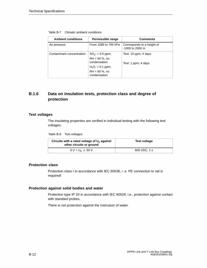
Technical Specifications
B-12DP/PA Link and Y Link Bus Couplings
A5E00193841-011
Table B-7 Climatic ambient conditions
Ambient conditions CommentsPermissible range
Air pressure From 1080 to 795 hPa Corresponds to a height of-1000 to 2000 m
Contaminant concentration SO2: < 0.5 ppm;
RH < 60 %, nocondensation
H2S: < 0.1 ppm;
RH < 60 %, nocondensation
Test: 10 ppm; 4 days
Test: 1 ppm; 4 days
B.1.6 Data on insulation tests, protection class and degree ofprotection
Test voltages
The insulating properties are verified in individual testing with the following testvoltages:
Table B-8 Test voltages
Circuits with a rated voltage of Ue againstother circuits or ground
Test voltage
0 V < Ue 50 V 600 VDC, 1 s
Protection class
Protection class I in accordance with IEC 60536, i. e. PE connection to rail isrequired!
Protection against solid bodies and water
Protection type IP 20 in accordance with IEC 60529; i.e., protection against contactwith standard probes.
There is not protection against the instrusion of water.

Technical Specifications
B-13DP/PA Link and Y Link Bus Couplings A5E00193841-011
B.1.7 Rated voltage
Rated voltages for operation
The described components work with a rated voltage of 24 VDC. The tolerancerange lies between 20.4 and 28.8 VDC.
B.2 Use of the DP/PA link coupler in the Zone 2 hazardousarea (in all official EU languages)
In the following sections you will find important information in all official EUlanguages.
Chapter overview
Section Topic Page
B.2.1 Einsatz der Buskopplung DP/PA im explosionsgefährdeten BereichZone 2
B-14
B.2.2 Use of the DP/PA coupler in a zone 2 hazardous area B-16
B.2.3 Utilisation du coupleur de bus DP/PA dans un environnement à risqued’explosion en zone 2
B-18
B.2.4 Aplicación del acoplamiento de bus DP/PA en áreas con peligro deexplosión, zona 2
B-20
B.2.5 Impiego dell’accoppiamento di bus DP/PA nell’area a pericolo diesplosione zona 2
B-22
B.2.6 Gebruik van de buskoppeling DP/PA in het explosieve gebied zone 2 B-24
B.2.7 Brug af buskoblingen DP/PA i det eksplosionfarlige område zone 2 B-26
B.2.8 Väyläkytkennän DP/PA käyttö räjähdysvaarannetuilla alueilla,vyöhyke 2
B-28
B.2.9 Användning av bussanslutning DP/PA i explosionsriskområde zon 2 B-30
B.2.10 Uso do acoplamento de bus DP/PA em área exposta ao perigo deexplosão, zona 2
B-32
B.2.11 Χρηση τηζ συσΚευηζ διαυλου DP/PA σε ... B-34
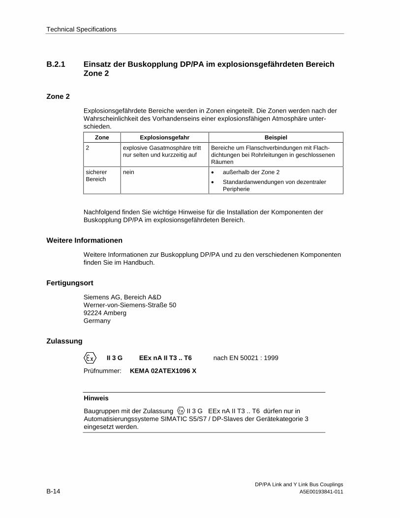
Technical Specifications
DP/PA Link and Y Link Bus CouplingsB-14 A5E00193841-011
B.2.1 Einsatz der Buskopplung DP/PA im explosionsgefährdeten BereichZone 2
Zone 2
Explosionsgefährdete Bereiche werden in Zonen eingeteilt. Die Zonen werden nach derWahrscheinlichkeit des Vorhandenseins einer explosionsfähigen Atmosphäre unter-schieden.
Zone Explosionsgefahr Beispiel
2 explosive Gasatmosphäre trittnur selten und kurzzeitig auf
Bereiche um Flanschverbindungen mit Flach-dichtungen bei Rohrleitungen in geschlossenenRäumen
sichererBereich
nein • außerhalb der Zone 2
• Standardanwendungen von dezentralerPeripherie
Nachfolgend finden Sie wichtige Hinweise für die Installation der Komponenten derBuskopplung DP/PA im explosionsgefährdeten Bereich.
Weitere Informationen
Weitere Informationen zur Buskopplung DP/PA und zu den verschiedenen Komponentenfinden Sie im Handbuch.
Fertigungsort
Siemens AG, Bereich A&DWerner-von-Siemens-Straße 5092224 AmbergGermany
Zulassung
II 3 G EEx nA II T3 .. T6 nach EN 50021 : 1999
Prüfnummer: KEMA 02ATEX1096 X
Hinweis
Baugruppen mit der Zulassung II 3 G EEx nA II T3 .. T6 dürfen nur inAutomatisierungssysteme SIMATIC S5/S7 / DP-Slaves der Gerätekategorie 3eingesetzt werden.

Technical Specifications
DP/PA Link and Y Link Bus CouplingsA5E00193841-011 B-15
Instandhaltung
Für eine Reparatur muss die betroffene Komponente an den Fertigungsort geschicktwerden. Nur dort darf die Reparatur durchgeführt werden.
Besondere Bedingungen
1. Die Buskopplung DP/PA muss in einen Schaltschrank oder ein metallisches Gehäuseeingebaut werden. Diese müssen mindestens die Schutzart IP 54 (nach EN 60529)gewährleisten. Dabei sind die Umgebungsbedingungen zu berücksichtigen, in denendas Gerät installiert wird. Für das Gehäuse muss eine Herstellererklärung für Zone 2vorliegen (gemäß EN 50021).
2. Wenn am Kabel bzw. an der Kabeleinführung dieses Gehäuses unter Betriebs-bedingungen eine Temperatur > 70 °C erreicht wird oder wenn unter Betriebs-bedingungen die Temperatur an der Aderverzweigung > 80 °C sein kann, müssen dieTemperatureigenschaften der Kabel mit den tatsächlich gemessenen Temperaturenübereinstimmen.
3. Die eingesetzten Kabeleinführungen müssen der geforderten IP-Schutzart und demAbschnitt 7.2 (gemäß EN 50021) entsprechen.
4. Alle Geräte, einschließlich Schalter etc., die an den Ein- und Ausgängen vonBuskopplungen DP/PA angeschlossen werden, müssen für den ExplosionsschutzTyp EEx nA oder EEx nC genehmigt sein.
5. Es müssen Maßnahmen getroffen werden, dass die Nennspannung durchTransienten um nicht mehr als 40 % überschritten werden kann.
6. Umgebungstemperaturbereich: 0° C bis 60° C
7. Innerhalb des Gehäuses ist an einem nach dem Öffnen gut sichtbaren Platz ein Schildmit folgender Warnung anzubringen:WarnungDas Gehäuse darf nur kurze Zeit geöffnet werden, z. B. für visuelle Diagnose.Betätigen Sie dabei keine Schalter, ziehen oder stecken keine Baugruppen undtrennen keine elektrischen Leitungen (Steckverbindungen).Diese Warnung kann unberücksichtigt bleiben, wenn bekannt ist, dass keineexplosionsgefährdete Atmosphäre herrscht.
Liste der zugelassenen Baugruppen
Die Liste mit den zugelassenen Baugruppen finden Sie im Internet:
http://www4.ad.siemens.de/view/cs/
unter der Beitrags-ID 13702947.

Technical Specifications
DP/PA Link and Y Link Bus CouplingsB-16 A5E00193841-011
B.2.2 Use of the DP/PA Bus Coupler in a Zone 2 Hazardous Area
Zone 2
Hazardous areas are divided up into zones. The zones are distinguished according to theprobability of the existence of an explosive atmosphere.
Zone Explosion Hazard Example
2 Explosive gas atmosphereoccurs only seldom and for ashort time
Areas around flange joints with flat gaskets inpipes in enclosed spaces
Safe area No • Outside zone 2
• Standard distributed I/O applications
Below you will find important information on the installation of the components of theDP/PA bus coupler in a hazardous area.
Further Information
You will find further information on the DP/PA bus coupler and the various components inthe manual.
Production Location
Siemens AG, Bereich A&DWerner-von-Siemens-Straße 5092224 AmbergGermany
Certification
II 3 G EEx nA II T3 .. T6 to EN 50021 : 1999
Test number: KEMA 01ATEX1238 X
Note
Modules with II 3 G EEx nA II T3 .. T6 certification can only be used inSIMATIC S7-300/ET 200M automation systems belonging to equipmentcategory 3.

Technical Specifications
DP/PA Link and Y Link Bus CouplingsA5E00193841-011 B-17
Maintenance
If repair is necessary, the affected component must be sent to the production location.Repairs can only be carried there.
Special Conditions
1. The DP/PA bus coupler must be installed in a cabinet or metal housing. These mustcomply with the IP 54 degree of protection as a minimum. The environmentalconditions under which the equipment is installed must be taken into account. Theremust be a manufacturer’s declaration for zone 2 available for the housing (inaccordance with EN 50021).
2. If a temperature of > 70 °C is reached in the cable or at the cable entry of this housingunder operating conditions, or if a temperature of > 80 °C can be reached at thejunction of the conductors under operating conditions, the temperature-relatedproperties of the cables must correspond to the temperatures actually measured.
3. The cable entries used must comply with the required IP degree of protection andSection 7.2 (in accordance with EN 50021).
4. All devices (including switches, etc.) that are connected to the inputs and outputs offail-safe signal modules must be approved for EEx nA or EEx nC explosion protection.
5. Steps must be taken to ensure that the rated voltage through transients cannot beexceeded by more than 40 %.
6. Ambient temperature range: 0° C to 60° C
7. A sign containing the following warning must be put up inside the housing in an easilyvisible position when the housing is opened:WarningThe housing can only be opened for a short time (e.g. for visual diagnostics). If you dothis, do not operate any switches, remove or install any modules or disconnect anyelectrical cables (plug-in connections).You can disregard this warning if you know that the atmosphere is not hazardous (i.e.there is no risk of explosion).
List of Approved Modules
You will find the list of approved modules under the ID 13702947 on the Internet:
http://www4.ad.siemens.de/view/cs/.
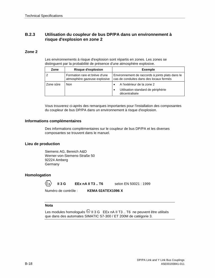
Technical Specifications
DP/PA Link and Y Link Bus CouplingsB-18 A5E00193841-011
B.2.3 Utilisation du coupleur de bus DP/PA dans un environnement àrisque d'explosion en zone 2
Zone 2
Les environnements à risque d'explosion sont répartis en zones. Les zones sedistinguent par la probabilité de présence d'une atmosphère explosive.
Zone Risque d’explosion Exemple
2 Formation rare et brève d'uneatmosphère gazeuse explosive
Environnement de raccords à joints plats dans lecas de conduites dans des locaux fermés
Zone sûre Non • A l'extérieur de la zone 2
• Utilisation standard de périphériedécentralisée
Vous trouverez ci-après des remarques importantes pour l'installation des composantesdu coupleur de bus DP/PA dans un environnement à risque d'explosion.
Informations complémentaires
Des informations complémentaires sur le coupleur de bus DP/PA et les diversescomposantes se trouvent dans le manuel.
Lieu de production
Siemens AG, Bereich A&DWerner-von-Siemens-Straße 5092224 AmbergGermany
Homologation
II 3 G EEx nA II T3 .. T6 selon EN 50021 : 1999
Numéro de contrôle : KEMA 02ATEX1096 X
Nota
Les modules homologués II 3 G EEx nA II T3 .. T6 ne peuvent être utilisésque dans des automates SIMATIC S7-300 / ET 200M de catégorie 3.
Technical Specifications
DP/PA Link and Y Link Bus CouplingsA5E00193841-011 B-19
Entretien
Si une réparation est nécessaire, la composante concernée doit être expédiée au lieu deproduction. La réparation ne doit être effectuée qu'en ce lieu.
Conditions particulières
1. Le couplage de bus DP/PA doit être installé dans une armoire ou un boîtiermétallique. Ceux-ci doivent assurer au moins l'indice de protection IP 54. Il faut alorstenir compte des conditions d'environnement dans lesquelles l'appareil est installé. Leboîtier doit faire l’objet d’une déclaration de conformité du fabricant pour la zone 2(selon EN 50021).
2. Si dans les conditions d’exploitation, une température > 70 °C est atteinte au niveaudu câble ou de l’entrée du câble dans ce boîtier, ou bien si la température au niveaude la dérivation des conducteurs peut être > 80 °C, les capacités de résistancethermique des câbles doivent corespondre aux températures effectivement mesurées.
3. Les entrées de câbles utilisées doivent avoir le niveau de protection IP exigé et êtreconformes au paragraphe 7.2 (selon EN 50021).
4. Tous les appareillages (y compris les interrupteurs, etc.) raccordés aux entrées etsorties de modules de signaux à sécurité intrinsèque doivent être homologués pour laprotection antidéflagrante type EEx nA ou EEx nC.
5. Il faut prendre des mesures pour que la tension nominale ne puisse pas êtredépassée de plus de 40% sous l’influence de transitoires.
6. Plage de température ambiante : 0° C à 60° C
7. A l’intérieur du boîtier, il faut placer, à un endroit bien visible après ouverture, uneplaquette comportant l’avertissement suivant :AvertissementOuvir le boîtier le moins longtemps possible, par exemple pour effectuer un diagnosticvisuel. Ce faisant, n’actionnez aucun commutateur, ne déconnectez aucun module etne débanchez pas de câbles électriques (connexions).Le respect de cet avertissement n’est pas impératif s’il est certain que l’environnementne présente pas de risque d’explosion.
Liste des modules homologués
Vous trouverez sur Internet la liste des modules homologués :
http://www4.ad.siemens.de/view/cs/
référence ID 13702947.
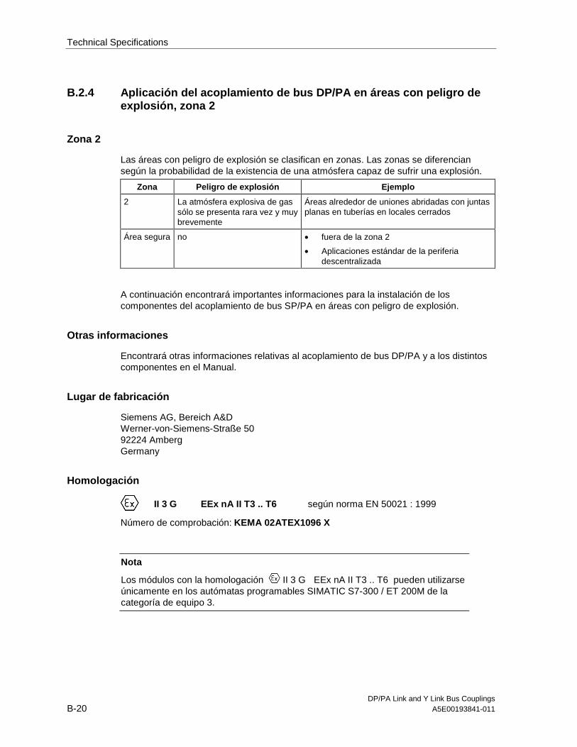
Technical Specifications
DP/PA Link and Y Link Bus CouplingsB-20 A5E00193841-011
B.2.4 Aplicación del acoplamiento de bus DP/PA en áreas con peligro deexplosión, zona 2
Zona 2
Las áreas con peligro de explosión se clasifican en zonas. Las zonas se diferenciansegún la probabilidad de la existencia de una atmósfera capaz de sufrir una explosión.
Zona Peligro de explosión Ejemplo
2 La atmósfera explosiva de gassólo se presenta rara vez y muybrevemente
Áreas alrededor de uniones abridadas con juntasplanas en tuberías en locales cerrados
Área segura no • fuera de la zona 2
• Aplicaciones estándar de la periferiadescentralizada
A continuación encontrará importantes informaciones para la instalación de loscomponentes del acoplamiento de bus SP/PA en áreas con peligro de explosión.
Otras informaciones
Encontrará otras informaciones relativas al acoplamiento de bus DP/PA y a los distintoscomponentes en el Manual.
Lugar de fabricación
Siemens AG, Bereich A&DWerner-von-Siemens-Straße 5092224 AmbergGermany
Homologación
II 3 G EEx nA II T3 .. T6 según norma EN 50021 : 1999
Número de comprobación: KEMA 02ATEX1096 X
Nota
Los módulos con la homologación II 3 G EEx nA II T3 .. T6 pueden utilizarseúnicamente en los autómatas programables SIMATIC S7-300 / ET 200M de lacategoría de equipo 3.

Technical Specifications
DP/PA Link and Y Link Bus CouplingsA5E00193841-011 B-21
Mantenimiento
Para una reparación se ha de remitir el componente afectado al lugar de fabricación.Sólo allí se puede realizar la reparación.
Condiciones especiales
1. El acoplamiento de bus DP/PA se ha de montar en un armario eléctrico dedistribución o en una carcasa metálica. Éstos deben garantizar como mínimo el gradode protección IP 54. Para ello se han de tener en cuenta las condiciones ambientales,en las cuales se instala el equipo. La caja deberá contar con una declaración delfabricante para la zona 2 (conforme a EN 50021).
2. Si durante la operación se alcanzara una temperatura > 70° C en el cable o la entradade cables de esta caja o bien una temperatura > 80° C en la bifurcación de hilos,deberán adaptarse las propiedades térmicas de los cables a las temperaturasmedidas efectivamente.
3. Las entradas de cable utilizadas deben cumplir el grado de protección IP exigido y loexpuesto en el apartado 7.2 (conforme a EN 50021).
4. Todos los dispositivos –inclusive interruptores, etc.– conectados a las entradas ysalidas de módulos de señales de alta disponibilidad deben estar homologados parala protección contra explosiones del tipo EEx nA o EEx nC.
5. Es necesario adoptar las medidas necesarias para evitar que la tensión nominalpueda rebasar en más del 40 % debido a efectos transitorios.
6. Margen de temperatura ambiente: 0° C hasta 60° C
7. Dentro de la caja deberá colocarse en un lugar perfectamente visible tras su aperturaun rótulo con la siguiente advertencia:PrecauciónAbrir la caja sólo brevemente, p.ej. para el diagnóstico visual. Durante este tiempoUd. no deberá activar ningún interruptor, desenchufar o enchufar módulos ni separarconductores eléctricos (conexiones enchufables).Esta advertencia puede ignorarse si Ud. sabe que en la atmósfera existente no haypeligro de explosión.
Lista de los módulos homologados
En la internet hallará Ud. una lista con los módulos homologados:
http://www4.ad.siemens.de/view/cs/
bajo el ID de asignación 13702947.

Technical Specifications
DP/PA Link and Y Link Bus CouplingsB-22 A5E00193841-011
B.2.5 Impiego dell’accoppiamento di bus DP/PA nell’area a pericolo diesplosione zona 2
Zona 2
Le aree a pericolo di esplosione vengono suddivise in zone. Le zone vengono distintesecondo la probabilità della presenza di un'atmosfera esplosiva.
Zona Pericolo di esplosione Esempio
2 L’atmosfera esplosiva sipresente solo raramente ebrevemente
Aree intorno a collegamenti a flange conguarnizioni piatte nelle condotte in ambienti chiusi
Area sicura No • Al di fuori della zona 2
• Applicazioni standard di periferia decentrata
Qui di seguito sono riportate delle avvertenze importanti per l'installazione deicomponenti dell'accoppiamento di bus DP/PA nell'area a pericolo di esplosione.
Ulteriori informazioni
Ulteriori informazioni sull'accoppiamento di bus DP/PA e sui diversi componenti sitrovano nel manuale.
Luogo di produzione
Siemens AG, Bereich A&DWerner-von-Siemens-Straße 5092224 AmbergGermany
Autorizzazione
II 3 G EEx nA II T3 .. T6 secondo EN 50021 : 1999
Numero di controllo: KEMA 02ATEX1096 X
Avvertenza
Le unità con l'autorizzazione II 3 G EEx nA II T3 .. T6 possono essereimpiegate solo nei sistemi di controllori programmabili SIMATIC S7-300 / ET 200Mdella categoria di apparecchiature 3.
Technical Specifications
DP/PA Link and Y Link Bus CouplingsA5E00193841-011 B-23
Manutenzione
Per una riparazione, il componente interessato deve essere inviato al luogo diproduzione. La riparazione può essere effettuata solo lì.
Condizioni particolari
1. L'accoppiamento di bus DP/PA deve essere montata in un armadio elettrico o in uncontenitore metallico. Questi devono assicurare almeno il tipo di protezione IP 54. Inquesto caso bisogna tenere conto delle condizioni ambientali nelle qualil'apparecchiatura viene installata. Per il contenitore deve essere presente unadichiarazione del costruttore per la zona 2 (secondo EN 50021).
2. Se nei cavi o nel loro punto di ingresso in questo contenitore viene raggiunta incondizioni di esercizio una temperatura > 70 °C o se in condizioni di esercizio latemperatura nella derivazione dei fili può essere > 80 °C, le caratteristiche ditemperatura dei cavi devono essere conformi alla temperatura effettivamentemisurata.
3. Gli ingressi dei cavi usati devono essere conformi al tipo di protezione richiesto e allasezione 7.2 (secondo EN 50021).
4. Tutte le apparecchiature, inclusi interruttori, ecc. che vengono collegati agliingressi/uscite di unità di segnale ad elevata sicurezza, devono essere stati omologatiper la protezione da esplosione tipo EEx nA o EEx nC.
5. Devono essere prese delle misure per evitare che la tensione nominale possa esseresuperata per più del 40% da parte di transienti.
6. Campo termico ambientale: da 0° C a 60° C
7. All’interno del contenitore va apportata, in un luogo ben visibile dopo l’apertura, unatarghetta con il seguente avvertimento:AttenzioneIl contenitore può rimanere aperto solo per breve tempo, ad esempio per unadiagnostica a vista. In tal caso non azionare alcun interruttore, non disinnestare oinnestare unità e non staccare connessioni elettriche (connettori).Non è necessario tenere conto di questo avvertimento se è noto che non c’èun’atmosfera a rischio di esplosione.
Elenco delle unità abilitate
La lista con le unità omologate si trova in Internet al sito:
http://www4.ad.siemens.de/view/cs/
all’ID di voce 13702947.

Technical Specifications
DP/PA Link and Y Link Bus CouplingsB-24 A5E00193841-011
B.2.6 Gebruik van de buskoppeling DP/PA in het explosieve gebied zone 2
Zone 2
Explosieve gebieden worden ingedeeld in zones. Bij de zones wordt onderscheidenvolgens de waarschijnlijkheid van de aanwezigheid van een explosieve atmosfeer.
Zone Explosiegevaar Voorbeeld
2 Een explosieve gasatmosfeertreedt maar zelden op en voorkorte duur
Gebieden rond flensverbindingen met pakkingenbij buisleidingen in gesloten vertrekken
Veiliggebied
neen • Buiten de zone 2
• Standaardtoepassingen van decentraleperiferie
Hierna vindt u belangrijke aanwijzingen voor de installatie van de componenten van debuskoppeling DP/PA in een explosief gebied.
Verdere informatie
In het handboek vindt u verdere informatie over de buskoppeling DP/PA en over deverschillende componenten.
Productieplaats
Siemens AG, Bereich A&DWerner-von-Siemens-Strasse 5092224 AmbergGermany
Vergunning
II 3 G EEx nA II T3 .. T6 conform EN 50021 : 1999
Keuringsnummer: KEMA 02ATEX1096 X
Opmerking
Modulen met de vergunning II 3 G EEx nA II T3 .. T6 mogen slechts wordengebruikt in automatiseringssystemen SIMATIC S7-300 / ET 200M van deapparaatcategorie 3.

Technical Specifications
DP/PA Link and Y Link Bus CouplingsA5E00193841-011 B-25
Instandhouding
De te herstellen component moet voor reparatie naar de plaats van vervaardiging wordengestuurd. Alleen daar mag de reparatie worden uitgevoerd.
Speciale voorwaarden
1. De buskoppeling DP/PA moet worden ingebouwd in een schakelkast of in eenbehuizing van metaal. Deze moeten minstens de veiligheidsgraad IP 54 waarborgen.Hierbij dient rekening te worden gehouden met de omgevingsvoorwaarden waarin hetapparaat wordt geïnstalleerd. Voor de behuizing dient een verklaring van de fabrikantvoor zone 2 te worden ingediend (volgens EN 50021).
2. Als aan de kabel of aan de kabelinvoering van deze behuizing onderbedrijfsomstandigheden een temperatuur wordt bereikt > 70 °C of als onderbedrijfsomstandigheden de temperatuur aan de adervertakking > 80 °C kan zijn,moeten de temperatuureigenschappen van de kabel overeenstemmen met dewerkelijk gemeten temperaturen.
3. De aangebrachte kabelinvoeringen moeten de vereiste IP-veiligheidsgraad hebben enin overeenstemming zijn met alinea 7.2 (volgens EN 50021).
4. Alle apparaten, schakelaars enz. inbegrepen, die worden aangesloten op de in- enuitgangen van tegen fouten beveiligde signaalmodulen, moeten zijn goedgekeurd voorde explosiebeveiliging type EEx nA of EEx nC.
5. Er dienen maatregelen te worden getroffen, zodat de nominale spanning doortransiënten met niet meer dan 40 % kan worden overschreden.
6. Omgevingstemperatuurbereik: 0° C tot 60° C
7. Binnen de behuizing dient op een na het openen goed zichtbare plaats een bord teworden aangebracht met de volgende waarschuwing:WaarschuwingDe behuizing mag slechts voor korte tijd worden geopend, bijv. voor een visuelediagnose. Bedien hierbij geen schakelaar, trek of steek geen modulen en ontkoppelgeen elektrische leidingen (steekverbindingen).Deze waarschuwing kan buiten beschouwing blijven, indien bekend is dat er geenexplosieve atmosfeer heerst.
Lijst van de toegelaten modulen
De lijst met de toegelaten modulen vindt u in het internet:
http://www4.ad.siemens.de/view/cs/
onder de bijdrage-ID 13702947.

Technical Specifications
DP/PA Link and Y Link Bus CouplingsB-26 A5E00193841-011
B.2.7 Brug af buskoblingen DP/PA i det eksplosionfarlige område zone 2
Zone 2
Eksplosionsfarlige områder inddeles i zoner. Zonerne adskiller sig indbyrdes efter hvorsandsynligt det er, at der er en eksplosiv atmosfære.
Zone Eksplosionsfare Eksempel
2 Eksplosiv gasatmosfæreoptræder kun sjældent og varerkort
Områder rundt om flangeforbindelser med fladepakninger ved rørledninger i lukkede rum
Sikkertområde
Nej • Uden for zone 2
• Standardanvendelser decentral periferi
I det følgende findes vigtige henvisninger vedr. installation af komponenterne tilbuskoblingen DP/PA i det eksplosionsfarlige område.
Yderligere informationer
Yderligere informationer om buskoblingen DP/PA og de forskellige komponenter findes imanualen.
Produktionssted
Siemens AG, Bereich A&DWerner-von-Siemens-Straße 5092224 AmbergGermany
Godkendelse
II 3 G EEx nA II T3 .. T6 efter EN 50021 : 1999
Kontrolnummer: KEMA 02ATEX1096 X
Bemærk
Komponenter med godkendelsen II 3 G EEx nA II T3 .. T6 må kun monteres iautomatiseringssystemer SIMATIC S7-300 / ET 200M - udstyrskategori 3.

Technical Specifications
DP/PA Link and Y Link Bus CouplingsA5E00193841-011 B-27
Vedligeholdelse
Skal den pågældende komponent repareres, bedes De sende den til produktionsstedet.Reparation må kun udføres der.
Særlige betingelser
1. Buskoblingen DP/PA skal monteres i et kontrolskab eller et metalkabinet. Disse skalmindst kunne sikre beskyttelsesklasse IP 54. I denne forbindelse skal der tages højdefor de omgivelsestemperaturer, i hvilke udstyret er installeret. Der skal væreudarbejdet en erklæring fra fabrikanten for kabinettet for zone 2 (iht. EN 50021).
2. Hvis kablet eller kabelindføringen på dette hus når op på en temperatur på > 70 °Cunder driftsbetingelser eller hvis temperaturen på åreforegreningen kan være > 80 °Cunder driftsbetingelser, skal kablernes temperaturegenskaber stemme overens medde temperaturer, der rent faktisk måles.
3. De benyttede kabelindføringer skal være i overensstemmelse med den krævede IP-beskyttelsestype og afsnittet 7.2 (iht. EN 50021).
4. Alle apparater, inkl. kontakter osv., der forbindes med ind- og udgangene til fejlsikresignalkomponenter, skal være godkendt til eksplosionsbeskyttelse af type EEx nAeller EEx nC.
5. Der skal træffes foranstaltninger, der sørger for, at den nominelle spænding viatransienter ikke kan overskrides mere end 40 %.
6. Omgivelsestemperaturområde: 0° C til 60° C
7. I kabinettet skal der anbringes et skilt, der skal kunne ses, når kabinettet åbnes. Detteskilt skal have følgende advarsel:AdvarselKabinettet må kun åbnes i kort tid, f.eks. til visuel diagnose. Tryk i denne forbindelseikke på kontakter, træk eller isæt ikke komponenter og afbryd ikke elektriske ledninger(stikforbindelser).Denne advarsel skal der ikke tages højde for, hvis man ved, at der ikke er nogeneksplosionsfarlig atmosfære.
Liste over godkendte komponenter
Listen med de godkendte komponenter findes på internettet:
http://www4.ad.siemens.de/view/cs/
under bidrags-ID 13702947.

Technical Specifications
DP/PA Link and Y Link Bus CouplingsB-28 A5E00193841-011
B.2.8 Väyläkytkennän DP/PA käyttö räjähdysvaarannetuilla alueilla,vyöhyke 2
Vyöhyke 2
Räjähdysvaarannetut alueet jaetaan vyöhykkeisiin. Vyöhykkeet erotellaanräjähdyskelpoisen ilmakehän olemassa olon todennäköisyyden mukaan.
Vyöhyke Räjähdysvaara Esimerkki
2 Räjähtävä kaasuilmakehäilmaantuu vain harvoin jalyhytaikaisesti
Alueet putkistojen lattatiivisteillä varustuillalaippaliitoksilla suljetuissa tiloissa
turvallinenalue
ei • vyöhykkeen 2 ulkopuolella
• Hajautetun ulkopiirin vakiosovellukset
Seuraavasta löydätte tärkeitä ohjeita väyläkytkennän DP/PA asennukseenräjähdysvaarannetuilla alueilla.
Lisätietoja
Lisätietoja väyläkytkentään DP/PA ja erilaisiin komponentteihin löydätte ohjekirjasta.
Valmistuspaikka
Siemens AG, Bereich A&DWerner-von-Siemens-Straße 5092224 AmbergGermany
Hyväksyntä
II 3 G EEx nA II T3 .. T6 EN 50021 mukaan: 1999
Tarkastusnumero: KEMA 02ATEX1096 X
Ohje
Rakenneryhmät hyväksynnän II 3 G EEx nA II T3 .. T6 kanssa saadaankäyttää ainoastaan laitekategorian 3 automatisointijärjestelmissä SIMATIC S7-300 /ET 200M.

Technical Specifications
DP/PA Link and Y Link Bus CouplingsA5E00193841-011 B-29
Kunnossapito
Korjausta varten täytyy kyseinen komponentti lähettää valmistuspaikkaan. Korjausvoidaan suorittaa ainoastaan siellä.
Erityiset vaatimukset
1. Väyläkytkentä DP/PA täytyy asentaa kytkentäkaappiin tai metalliseen koteloon.Näiden täytyy olla vähintään kotelointiluokan IP 54 mukaisia. Tällöin on huomioitavaympäristöolosuhteet, johon laite asennetaan. Kotelolle täytyy olla valmistajaselvitysvyöhykettä 2 varten (EN 50021 mukaan).
2. Kun johdolla tai tämän kotelon johdon sisäänviennillä saavutetaan > 70 °C lämpötilatai kun käyttöolosuhteissa lämpötila voi piuhajaotuksella olla > 80 °C, täytyy johdonlämpötilaominaisuuksien vastata todellisesti mitattuja lämpötiloja.
3. Käytettyjen johtojen sisäänohjauksien täytyy olla vaaditun IP-kotelointiluokan jakohdan 7.2 (EN 50021 mukaan) mukaisia.
4. Kaikkien laitteiden, kytkimet jne. mukaan lukien, jotka liitetään virheiltä suojattujensignaalirakenneryhmien tuloille ja lähdöille, täytyy olla hyväksyttyjä tyypin EEx nA taiEEx nC räjähdyssuojausta varten.
5. Toimenpiteet täytyy suorittaa, ettei nimellisjännite voi transienttien kautta ylittyäenemmän kuin 40 %.
6. Ympäristölämpötila-alue: 0° C ... 60° C
7. Kotelon sisälle, avauksen jälkeen näkyvälle paikalle, on kiinnitettävä kilpi, jossa onseuraava varoitus:VaroitusKotelo saadaan avata ainoastaan lyhyeksi ajaksi, esim. visuaalista diagnoosia varten.Älä tällöin käytä mitään kytkimiä, vedä tai liitä mitään rakenneryhmiä, äläkä erotamitään sähköjohtoja (pistoliittimiä).Tätä varoitusta ei tarvitse huomioida, kun on tiedossa, että minkäänlaistaräjähdysvaarannettua ilmakehää ei ole olemassa.
Hyväksyttyjen rakenneryhmien lista
Lista hyväksiytyistä rakennesarjoista löytyy internetistä osoitteesta:
http://www4.ad.siemens.de/view/cs/
käyttäjätunnuksella 13702947.

Technical Specifications
DP/PA Link and Y Link Bus CouplingsB-30 A5E00193841-011
B.2.9 Användning av bussanslutning DP/PA i explosionsriskområde zon 2
Zon 2
Explosionsriskområden delas in i zoner. Zonerna delas in enligt sannolikheten att enatmosfär med explosionsfara föreligger.
Zon Explosionsfara Exempel
2 Explosiv gasatmosfär uppstårendast sällan eller kortvarigt
Områden kring flänsförbindelser med packningarvid rörledningar i slutna utrymmen
Säkertområde
Nej • Utanför zon 2
• Standardanvändning av decentral periferi
Nedan följer viktiga anvisningar om installationen av DP/PA-bussanslutningenskomponenter i ett explosionsriskområde.
Ytterligare information
Ytterligare information om DP/PA-bussanslutningen och de olika komponenterna finnerdu i handboken.
Tillverkningsort
Siemens AG, Bereich A&DWerner-von-Siemens-Straße 5092224 AmbergGermany
Godkännande
II 3 G EEx nA II T3 .. T6 enligt EN 50021 : 1999
Kontrollnummer: KEMA 02ATEX1096 X
Anvisning
Komponentgrupper med godkännande II 3 G EEx nA II T3 .. T6 får endastanvändas i automatiseringssystemen SIMATIC S7-300 / ET°200M frånapparatgrupp 3.

Technical Specifications
DP/PA Link and Y Link Bus CouplingsA5E00193841-011 B-31
Underhåll
Vid reparation måste den aktuella komponenten insändas till tillverkaren. Reparationer fårendast genomföras där.
Särskilda villkor
1. Busskopplingen°DP/PA måste monteras i ett kopplingsskåp eller metallhus. Dessamåste minst vara av skyddsklass IP 54. Därvid ska omgivningsvillkoren där enheteninstalleras beaktas. För kåpan måste en tillverkardeklaration för zon 2 föreligga (enligtEN 50021).
2. Om en temperatur på > 70°C uppnås vid husets kabel resp kabelinföring underdriftvillkor eller om temperaturen vid trådförgreningen kan vara > 80°C underdriftvillkor, måste kabelns temperaturegenskaper överensstämma med den verkligenuppmätta temperaturen.
3. De använda kabelinföringarna måste uppfylla kraven i det krävda IP-skyddsutförandetoch i avsnitt 7.2 (enligt EN 50021).
4. Alla apparater, inklusive brytare osv, som ansluts till felsäkrade signalenheters in- ochutgångar, måste vara godkända för explosionsskydd av typ EEx nA eller EEx nC.
5. Åtgärder måste vidtas så, att märkspänningen ej kan överskridas med mer än 40°%genom transienter.
6. Omgivningstemperatur: 0° C till 60° C
7. När huset öppnats ska en skylt med följande varning monteras på ett tydligt synligtställe huset:VarningHuset får endast öppnas under kort tid, t ex för visuell diagnos. Använd därvid ingabrytare, lossa eller anslut inga enheter och frånskilj inga elektriska ledningar(insticksanslutningar).Ingen hänsyn måste tas till denna varning om det är säkert att det inte råder någonexplosionsfarlig atmosfär.
Lista över godkända komponentgrupper
Lista över godkända enheter återfinns i Internet:
http://www4.ad.siemens.de/view/cs/
under bidrags-ID 13702947.
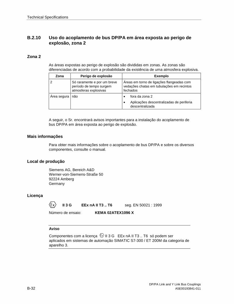
Technical Specifications
DP/PA Link and Y Link Bus CouplingsB-32 A5E00193841-011
B.2.10 Uso do acoplamento de bus DP/PA em área exposta ao perigo deexplosão, zona 2
Zona 2
As áreas expostas ao perigo de explosão são divididas em zonas. As zonas sãodiferenciadas de acordo com a probabilidade da existência de uma atmosfera explosiva.
Zona Perigo de explosão Exemplo
2 Só raramente e por um breveperíodo de tempo surgematmosferas explosivas
Áreas em torno de ligações flangeadas comvedações chatas em tubulações em recintosfechados
Área segura não • fora da zona 2
• Aplicações descentralizadas de periferiadescentralizada
A seguir, o Sr. encontrará avisos importantes para a instalação do acoplamento debus DP/PA em área exposta ao perigo de explosão.
Mais informações
Para obter mais informações sobre o acoplamento de bus DP/PA e sobre os diversoscomponentes, consulte o manual.
Local de produção
Siemens AG, Bereich A&DWerner-von-Siemens-Straße 5092224 AmbergGermany
Licença
II 3 G EEx nA II T3 .. T6 seg. EN 50021 : 1999
Número de ensaio: KEMA 02ATEX1096 X
Aviso
Componentes com a licença II 3 G EEx nA II T3 .. T6 só podem seraplicados em sistemas de automação SIMATIC S7-300 / ET 200M da categoria deaparelho 3.

Technical Specifications
DP/PA Link and Y Link Bus CouplingsA5E00193841-011 B-33
Reparo
Os componentes em questão devem ser remetidos para o local de produção a fim deque seja realizado o reparo. Apenas lá deve ser efetuado o reparo.
Condições especiais
1. O acoplamento do bus DP/PA deve ser montado em um armário de distribuição ouem uma caixa metálica. Estes devem garantir no mínimo o tipo de proteção IP 54.Durante este trabalho deverão ser levados em consideração as condições locais, nasquais o aparelho será instalado. Para a caixa deverá ser apresentada uma declaraçãodo fabricante para a zona 2 (de acordo com EN 50021).
2. Caso no cabo ou na entrada do cabo desta carcaça sob as condições operacionaisseja atingida uma temperatura de > 70 °C, ou caso sob condições operacionais atemperatura na ramificação do fio poderá atingir > 80 °C, as caraterísticas detemperatura deverão corresponder às temperaturas realmente medidas.
3. As entradas de cabo utilizadas devem corresponder ao tipo exigido de proteção IP e àseção 7.2 (de acordo com o EN 50021).
4. Todos os aparelhos, inclusive as chaves, etc., que estejam conectadas em entradas esaídas de módulos de sinais protegidos contra erro, devem possuir a licença para aproteção de explosão do tipo EEx nA ou EEx nC.
5. Precisam ser tomadas medidas para que a tensão nominal através de transitórios nãopossa ser ultrapassada em mais que 40 %.
6. Área de temperatura ambiente: 0° C até 60° C
7. No âmbito da carcaça deve ser colocada, após a abertura, em um ponto bem visíveluma placa com a seguinte advertência:AdvertênciaA carcaça deve ser aberta apenas por um breve período de tempo, por ex. paradiagnóstico visual. Não acione nenhum interruptor, não retire ou conecte nenhummódulo e não separe nenhum fio elétrico (ligações de tomada).Esta advertência poderá ser ignorada caso se saiba que não há nenhuma atmosferasujeita ao perigo de explosão.
Lista dos componentes autorizados
A lista com os módulos autorizados encontram-se na Internet:
http://www4.ad.siemens.de/view/cs/
sob o número de ID 13702947.

Technical Specifications
DP/PA Link and Y Link Bus CouplingsB-34 A5E00193841-011
B.2.11 2
2
. .
2
• 2
•
DP/PA .
DP/PA
Siemens AG, Bereich A&DWerner-von-Siemens-Straße 5092224 AmbergGermany
II 3 G EEx nA II T3 .. T6 50021 : 1999
: KEMA 02ATEX1096 X
II 3 G EEx nA II T3 .. T6 SIMATIC S7-300 / ET 200M
3.

Technical Specifications
DP/PA Link and Y Link Bus CouplingsA5E00193841-011 B-35
. .
1. DP/PA .
IP 54. , .
EN 50021).
2. 70 °C
80 °C, .
3. IP EN 50021).
4. EEx nA EEx nC.
5. %.
6. : 0° C 60° C
7.
http://www4.ad.siemens.de/view/cs/

Technical Specifications
B-36DP/PA Link and Y Link Bus Couplings
A5E00193841-011
B.3 Technical specifications of the IM 157(6ES7 157-0AA82-0XA0)
Dimensions and weight
Dimensions WHD (mm)
40125130
Weight Approx. 350 g
Module-specific data
Transmission rate ofhigher level DP mastersystem
9,6; 19,2; 45,45; 93,75;187,5; 500 kBaud1,5; 3, 6, 12 MBaud
Bus protocol PROFIBUS-DP
Frame length of I/O data Max. 244 bytes
Configuration framelength
Max. 244 bytes
Diagnostic frame length Max. 231 bytes
Parameter assignmentframe length
Max. 214 bytes
Suitable for systemchanges duringoperation:
Yes
Voltages, currents, potentials
Rated supply voltage 24 VDC (20.4 V ... 28.8 V)
Polarity reversalprotection
Yes
Power failurebridging
20 ms
Isolation
To underlying DPmaster system
Yes
To DP/PA or Ycoupler
No
Insulation tested at 500 VDC
Use in DP/PA link
Power input (24 VDC)
Max. 100 mA
Power loss Typically 2 W
Use in Y link
Power input (24 VDC)
Max. 200 mA
Power loss Typically 4 W
Status, interrupts, diagnostics
Status display No
Interrupts Yes
Diagnostic function Yes
Group error Red “SF” LED
Bus error on higherlevel DP mastersystem
Red ”BF 1” LED
Bus error onunderlying bussystem
Red ”BF 2” LED
IM has an activechannel
Yellow ”ACT” LED
24 V supplymonitoring
Green “ON” LED
Data on connection of underlying bus compo-nents
Connectable DP/PAcoupler
Max. 5
Connectable Y coupler 1
Connectable underlyingslaves
Max. 64
Number of slots inunderlying slaves
Max. 236 or(244 – number of PAfield devices)
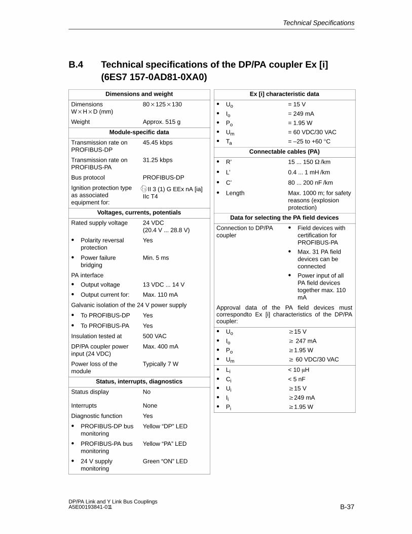
Technical Specifications
B-37DP/PA Link and Y Link Bus Couplings A5E00193841-011
B.4 Technical specifications of the DP/PA coupler Ex [i](6ES7 157-0AD81-0XA0)
Dimensions and weight
Dimensions WHD (mm)
80125130
Weight Approx. 515 g
Module-specific data
Transmission rate onPROFIBUS-DP
45.45 kbps
Transmission rate onPROFIBUS-PA
31.25 kbps
Bus protocol PROFIBUS-DP
Ignition protection typeas associatedequipment for:
II 3 (1) G EEx nA [ia]IIc T4
Voltages, currents, potentials
Rated supply voltage 24 VDC (20.4 V ... 28.8 V)
Polarity reversalprotection
Yes
Power failurebridging
Min. 5 ms
PA interface
Output voltage 13 VDC ... 14 V
Output current for: Max. 110 mA
Galvanic isolation of the 24 V power supply
To PROFIBUS-DP Yes
To PROFIBUS-PA Yes
Insulation tested at 500 VAC
DP/PA coupler powerinput (24 VDC)
Max. 400 mA
Power loss of themodule
Typically 7 W
Status, interrupts, diagnostics
Status display No
Interrupts None
Diagnostic function Yes
PROFIBUS-DP busmonitoring
Yellow “DP” LED
PROFIBUS-PA busmonitoring
Yellow “PA” LED
24 V supplymonitoring
Green “ON” LED
Ex [i] characteristic data
Uo
Io Po
Um
Ta
= 15 V
= 249 mA
= 1.95 W
= 60 VDC/30 VAC
= –25 to +60 °C
Connectable cables (PA)
R’ 15 ... 150 /km
L’ 0.4 ... 1 mH /km
C’ 80 ... 200 nF /km
Length Max. 1000 m; for safetyreasons (explosionprotection)
Data for selecting the PA field devices
Connection to DP/PAcoupler
Field devices withcertification forPROFIBUS-PA
Max. 31 PA fielddevices can beconnected
Power input of allPA field devicestogether max. 110mA
Approval data of the PA field devices mustcorrespondto Ex [i] characteristics of the DP/PAcoupler:
Uo
Io Po
Um
15 V
247 mA
1.95 W
60 VDC/30 VAC
Li
Ci
Ui
Ii Pi
< 10 H
< 5 nF
15 V
249 mA
1.95 W

Technical Specifications
B-38DP/PA Link and Y Link Bus Couplings
A5E00193841-011
B.5 Technical specifications of the DP/PA coupler(6ES7 157-0AC80-0XA0)
Dimensions and weight
Dimensions WHD (mm)
80125130
Weight Approx. 515 g
Module-specific data
Transmission rate onPROFIBUS-DP
45.45 kbps
Transmission rate onPROFIBUS-PA
31.25 kbps
Bus protocol PROFIBUS-DP
Voltages, currents, potentials
Rated supply voltage 24 VDC (20.4 V ... 28.8 V)
Polarity reversalprotection
Yes
Output voltage for PApart:
Typically 19 VDC
Power failurebridging
Min. 5 ms
Galvanic isolation of the 24 V power supply
To PROFIBUS-DP Yes
To PROFIBUS-PA Yes
Insulation tested at 500 VDC
DP/PA coupler powerinput (24 VDC)
Max. 0.75 A
PA part output current(for sizing of the PAconfiguration)
400 mA
Power loss of themodule
Typically 7 W
Status, interrupts, diagnostics
Status display No
Interrupts None
Diagnostic function Yes
PROFIBUS-DP busmonitoring
Yellow “DP” LED
PROFIBUS-PA busmonitoring
Yellow “PA” LED
24 V supplymonitoring
Green “ON” LED
Data for selecting the PA field devices
Connection to DP/PAcoupler
Max. power input ofthe PA field devicestogether 400 mA
Field devices withcertification forPROFIBUS-PA
Field devices areoutside thehazardous area
Max. 31 PA fielddevices can beconnected
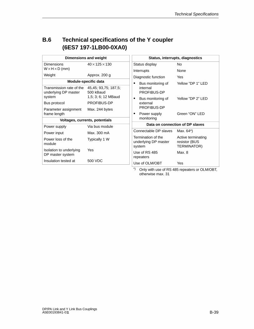
Technical Specifications
B-39DP/PA Link and Y Link Bus Couplings A5E00193841-011
B.6 Technical specifications of the Y coupler(6ES7 197-1LB00-0XA0)
Dimensions and weight
Dimensions WHD (mm)
40125130
Weight Approx. 200 g
Module-specific data
Transmission rate of theunderlying DP mastersystem
45,45; 93,75; 187,5;500 kBaud1,5; 3; 6; 12 MBaud
Bus protocol PROFIBUS-DP
Parameter assignmentframe length
Max. 244 bytes
Voltages, currents, potentials
Power supply Via bus module
Power input Max. 300 mA
Power loss of themodule
Typically 1 W
Isolation to underlyingDP master system
Yes
Insulation tested at 500 VDC
Status, interrupts, diagnostics
Status display No
Interrupts None
Diagnostic function Yes
Bus monitoring ofinternalPROFIBUS-DP
Yellow ”DP 1” LED
Bus monitoring ofexternalPROFIBUS-DP
Yellow ”DP 2” LED
Power supplymonitoring
Green “ON” LED
Data on connection of DP slaves
Connectable DP slaves Max. 64*)
Termination of theunderlying DP mastersystem
Active terminatingresistor (BUSTERMINATOR)
Use of RS 485repeaters
Max. 8
Use of OLM/OBT Yes*) Only with use of RS 485 repeaters or OLM/OBT,
otherwise max. 31

Technical Specifications
B-40DP/PA Link and Y Link Bus Couplings
A5E00193841-011

C-1DP/PA Link and Y Link Bus Couplings A5E00193841-011
DP Slaves Connectable to a Y Link
Using STEP 7 of version V5.2 or higher, many DP slaves can be directlyconfigured in the underlying DP master system of a Y link.
Table C-1 Examples of directly configurable DP slaves
Group (path1)) Configurable slaves MLFB
Preconfigured stations PC station as a DP slave –
S7-300 CP 342-5 DP All
DP/AS-i DP/AS-i Link 6ES7 156-0AA00-0XA0
DP/AS-i DP/AS-i lLink 20 6GK1415-2AA00
ENCODER SIMODRIVE Sensor 6FX2001-5xPxx
ET 200B Most components with the exceptionof S7 slaves ET 200B-4AI,ET 200B-4/8AI and ET 200B-4AO
Not6ES7 134-0HF01-0XB0,6ES7 134-0KH01-0XB0,6ES7 135-0HF01-0XB0
ET 200L Most components with the exceptionof the extendable module L-SC-...
ET 200S Most components with the exceptionof the IM 151 / CPU
Not6ES7 151-7AA00-0AB0
Function modules IM 178-4 6ES7 178-4BH00-0AE0
IPC Direct control key module
NC IM 319N (slave) 6FC5012-0CA02-0AA0
Control unit SIPART DR**
Switchgear Interface module DP/RS 485 3RK1000-0JC80-0BA1
SIMOCODE-DP
SIMADYN SIMADYN D SS52 6DD1688-0AE2
1) In hardware catalog based on “PROFIBUS-DP”
Nearly all of the components in the following groups are directly configurable: ET 200C,ET 200U, IDENT, SIMATIC, SIMODRIVE, SIMOREG, SIMOVERT and SIPOS.
DP slaves that are not allowed by STEP 7 can be configured as DPV0 standardslaves by means of the device master file, provided that they are not subject to therestrictions presented below.
C

DP Slaves Connectable to a Y Link
C-2DP/PA Link and Y Link Bus Couplings
A5E00193841-011
Restrictions
In the underlying DP master system, operator panels and text displays can onlybe operated as DP slaves and not as active bus nodes.
Slaves in the DPV1 mode cannot be operated in the underlying DP mastersystem if the Y link is in DPV0 mode (DP master in “S7-compatible” mode).
Configuration of S7-300/S7-400 stations as I slaves
The CPU for an S7-300 or S7-400 station cannot be used out of the “preconfiguredstations” catalog directory but must be integrated via the device master file.
When configuring the S7-300/S7-400 station, a “dummy” DP system must becreated that has the same bus settings (transmission rates, etc.) as the underlyingDP master system of the Y link but not the same bus name. The station number ofthe S7-300/S7-400 must coincide with the slave address on the Y link.
Examples of usable DP slaves
The table below shows a selection of field devices that can be defined via thedevice master file as DP slaves. It also presents all of the S7-CPUs that can beused as I slaves with various I/O ranges.
Table C-2 Examples of usable DP slaves
Slave name Path1) Device masterfile
Input bytes Outputbytes
Number ofslaves 2)
Gateway 3WN6 Switchgear Siem8032.gs* Max. 12 Max. 12 20 3)
ET 200X with BM147/CPUas I slave with various I/Oranges
I/O\ET200X Siem804a.gs* Max. 244 Max. 244 1 3)
SIMOCODE-DP with theType 1 Compact basicmodule
Switchgear\SIMOCODE
Siem8031.gs* 12 4 20
SIMODRIVE 611U with 1 axis, PPO Type 5
Drives\SIMODRIVE
Siem8055.gsd 28 28 8
SIMODRIVE 611U with 2 axes, PPO Type 5
56 56 4
SIMODRIVE POSMO A Drives\SIMODRIVE
Siem8054.gsd 12 12 20
Heating control HS 724 General\OTHER
Siem002b.gsd 32 32 7
1) In the hardware catalog based on “PROFIBUS-DP\Additional FIELD DEVICES”
2) Number of slaves of the same kind that exhaust the capacity of the I/O quantity structure of the Y link
3) Applies when the maximum number of slaves is installed

DP Slaves Connectable to a Y Link
C-3DP/PA Link and Y Link Bus Couplings A5E00193841-011
Table C-3 CPUs that can be used as I slaves with various I/O ranges
Slave name Path1) Device masterfile
Input bytes Outputbytes
Number ofslaves 2)
S7-300 CPU 315-2DP(...-2AF01-... or...-2AF02-...)
SPS\SIMATIC Siem802f.gs* Max. 122 Max. 122 1 3)
S7-300 CPU 315-2DP(...-2AF03-... )
SPS\SIMATIC Sie3802f.gs* Max. 244 Max. 244 1 3)
S7-300 CPU 316-2DP SPS\SIMATIC Siem806f.gs* Max. 244 Max. 244 1 3)
S7-300 CPU 318-2DP SPS\SIMATIC Siem807f.gs* Max. 244 Max. 244 1 3)
S7-400 CPU 412-1 SPS\SIMATIC Siem80c5.gs* Max. 244 Max. 244 1 3)
S7-400 CPU 412-2 SPS\SIMATIC Siem80c6.gs* Max. 244 Max. 244 1 3)
S7-400 CPU 414-2 SPS\SIMATIC Siem80c7.gs* Max. 244 Max. 244 1 3)
S7-400 CPU 414-3 SPS\SIMATIC Siem80c8.gs* Max. 244 Max. 244 1 3)
S7-400 CPU 416-2 SPS\SIMATIC Siem80ca.gs* Max. 244 Max. 244 1 3)
S7-400 CPU 416-3 SPS\SIMATIC Siem80cb.gs* Max. 244 Max. 244 1 3)
S7-400 CPU 417-4 SPS\SIMATIC Siem80cc.gs* Max. 244 Max. 244 1 3)
1) In the hardware catalog based on “PROFIBUS-DP\Additional FIELD DEVICES”
2) Number of slaves of the same kind that exhaust the capacity of the I/O quantity structure of the Y link
3) Applies when the maximum number of slaves is installed

DP Slaves Connectable to a Y Link
C-4DP/PA Link and Y Link Bus Couplings
A5E00193841-011
Configuration example
An S7-300 with a CPU 315-2DP as an I slave with various I/O ranges
Two SIMODRIVE 611U with two axes each, PPO Type 5
One heating control HS 724
Figure C-1 Configuration example (excerpt from HW Config)
DPaddress
Slave Input bytes Outputbytes
3 S7-300 with CPU 315-2DP 1) 100 100
4 SIMODRIVE 611U with 2 axes, PPO Type 5 56 56
5 SIMODRIVE 611U with 2 axes, PPO Type 5 56 56
6 Heating control HS 724 32 32
Total 244 244
1) The actual hardware configuration of the station is irrelevant here. The only factor thatcounts are the I/O ranges that are transparent to the H system.
Thus, the maximum frame length for the input data and output data has beenreached for the underlying DP master system. No additional slaves can beoperated on this DP master system.
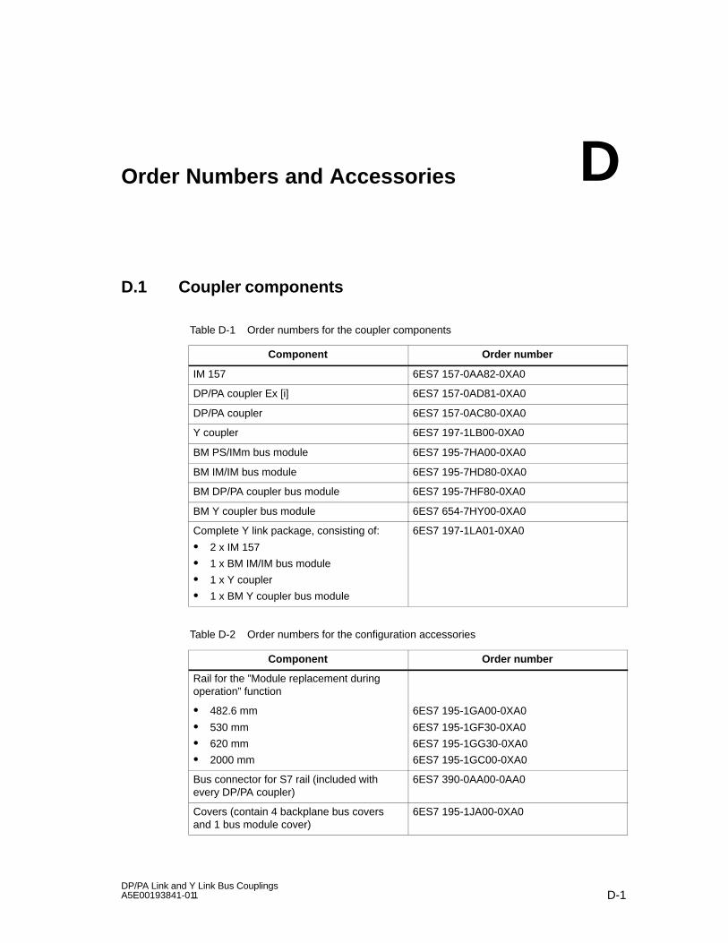
D-1DP/PA Link and Y Link Bus Couplings A5E00193841-011
Order Numbers and Accessories
D.1 Coupler components
Table D-1 Order numbers for the coupler components
Component Order number
IM 157 6ES7 157-0AA82-0XA0
DP/PA coupler Ex [i] 6ES7 157-0AD81-0XA0
DP/PA coupler 6ES7 157-0AC80-0XA0
Y coupler 6ES7 197-1LB00-0XA0
BM PS/IMm bus module 6ES7 195-7HA00-0XA0
BM IM/IM bus module 6ES7 195-7HD80-0XA0
BM DP/PA coupler bus module 6ES7 195-7HF80-0XA0
BM Y coupler bus module 6ES7 654-7HY00-0XA0
Complete Y link package, consisting of:
2 x IM 157
1 x BM IM/IM bus module
1 x Y coupler
1 x BM Y coupler bus module
6ES7 197-1LA01-0XA0
Table D-2 Order numbers for the configuration accessories
Component Order number
Rail for the ”Module replacement duringoperation” function
482.6 mm
530 mm
620 mm
2000 mm
6ES7 195-1GA00-0XA0
6ES7 195-1GF30-0XA0
6ES7 195-1GG30-0XA0
6ES7 195-1GC00-0XA0
Bus connector for S7 rail (included withevery DP/PA coupler)
6ES7 390-0AA00-0AA0
Covers (contain 4 backplane bus coversand 1 bus module cover)
6ES7 195-1JA00-0XA0
D
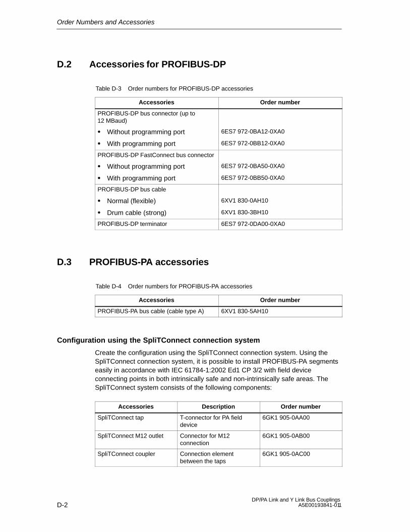
Order Numbers and Accessories
D-2DP/PA Link and Y Link Bus Couplings
A5E00193841-011
D.2 Accessories for PROFIBUS-DP
Table D-3 Order numbers for PROFIBUS-DP accessories
Accessories Order number
PROFIBUS-DP bus connector (up to12 MBaud)
Without programming port 6ES7 972-0BA12-0XA0
With programming port 6ES7 972-0BB12-0XA0
PROFIBUS-DP FastConnect bus connector
Without programming port 6ES7 972-0BA50-0XA0
With programming port 6ES7 972-0BB50-0XA0
PROFIBUS-DP bus cable
Normal (flexible) 6XV1 830-0AH10
Drum cable (strong) 6XV1 830-3BH10
PROFIBUS-DP terminator 6ES7 972-0DA00-0XA0
D.3 PROFIBUS-PA accessories
Table D-4 Order numbers for PROFIBUS-PA accessories
Accessories Order number
PROFIBUS-PA bus cable (cable type A) 6XV1 830-5AH10
Configuration using the SpliTConnect connection system
Create the configuration using the SpliTConnect connection system. Using theSpliTConnect connection system, it is possible to install PROFIBUS-PA segmentseasily in accordance with IEC 61784-1:2002 Ed1 CP 3/2 with field deviceconnecting points in both intrinsically safe and non-intrinsically safe areas. TheSpliTConnect system consists of the following components:
Accessories Description Order number
SpliTConnect tap T-connector for PA fielddevice
6GK1 905-0AA00
SpliTConnect M12 outlet Connector for M12connection
6GK1 905-0AB00
SpliTConnect coupler Connection elementbetween the taps
6GK1 905-0AC00
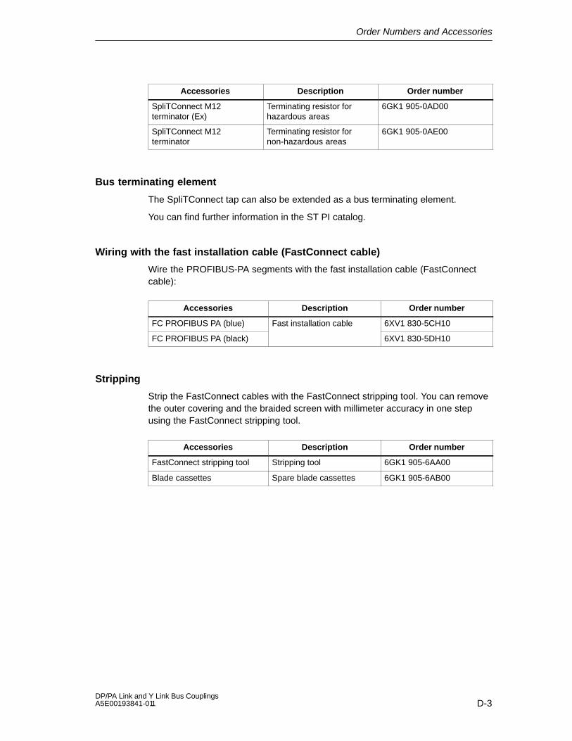
Order Numbers and Accessories
D-3DP/PA Link and Y Link Bus Couplings A5E00193841-011
Accessories Order numberDescription
SpliTConnect M12terminator (Ex)
Terminating resistor forhazardous areas
6GK1 905-0AD00
SpliTConnect M12terminator
Terminating resistor fornon-hazardous areas
6GK1 905-0AE00
Bus terminating element
The SpliTConnect tap can also be extended as a bus terminating element.
You can find further information in the ST PI catalog.
Wiring with the fast installation cable (FastConnect cable)
Wire the PROFIBUS-PA segments with the fast installation cable (FastConnectcable):
Accessories Description Order number
FC PROFIBUS PA (blue) Fast installation cable 6XV1 830-5CH10
FC PROFIBUS PA (black) 6XV1 830-5DH10
Stripping
Strip the FastConnect cables with the FastConnect stripping tool. You can removethe outer covering and the braided screen with millimeter accuracy in one stepusing the FastConnect stripping tool.
Accessories Description Order number
FastConnect stripping tool Stripping tool 6GK1 905-6AA00
Blade cassettes Spare blade cassettes 6GK1 905-6AB00

Order Numbers and Accessories
D-4DP/PA Link and Y Link Bus Couplings
A5E00193841-011

Glossary-1DP/PA Link and Y Link Bus Couplings A5E00193841-011
Glossary
Address
The address of a node is used to localize it in the network. It must be uniquethroughout the entire system.
Aggregate current
Aggregate current of all the PA field devices.
Automation system
An automation system is a programmable logic controller that consists of at leastone CPU, various input and output modules and human-machine interfaces.
Bus
Shared transmission path to which all nodes are connected; possesses twodefined ends.
Bus connector
Physical connection between the bus node and the bus cable.
Coupler
The DP/PA coupler connects a PROFIBUS-PA segment to a PROFIBUS-DPsegment. PROFIBUS-PA and PROFIBUS-DP are linked in terms of data but arebased on different types of transmission media.
Device master file
All slave-specific characteristics are stored in a device master file (GSD file). Theformat of the device master file is provided in the PROFIBUS Guideline:Specification for PROFIBUS Device Description and Device Integration Vol.1:GSD V4.1, 07/2001 of the PROFIBUS Nutzerorganisation (PNO).

Glossary
Glossary-2DP/PA Link and Y Link Bus Couplings
A5E00193841-011
Diagnostic interrupt
Diagnostics-capable modules use diagnostic interrupts to report system errorsthat they have detected to the central CPU.
In SIMATIC S7/M7: When an error is detected or disappears (e. g. wire break),the module triggers a diagnostic interrupt, provided the interrupt is enabled. TheCPU interrupts the processing of the user program and lower priority classes,and processes the diagnostic interrupt block (OB 82).
In SIMATIC S5: The diagnostic interrupt appears in the station diagnosis. Usingcyclical querying of the diagnostic bits in the station diagnosis, you can detecterrors such as a wire break.
Diagnostics
Diagnostics is the detection, localization, classification, display and evaluation oferrors, faults and messages.
Diagnostics provides monitoring functions that run automatically while the systemis in operation. This increases the availability of systems by reducingcommissioning times and downtimes.
DP master
A master that behaves in accordance with IEC 61784-1:2002 Ed1 CP 3/1 isreferred to as a DP master.
DP slave
A slave run on the PROFIBUS bus system with the PROFIBUS-DP protocolthat behaves in accordance with the IEC 61784-1:2002 Ed1 CP 3/1 is referred toas a DP slave.
DP standard
The DP standard is the bus protocol of the distributed I/O system in accordancewith IEC 61784-1:2002 Ed1 CP 3/1.
DPV0
Cyclical data exchange between the higher level system and slaves
Configuration by means of device master files
Diagnostics
Glossary
Glossary-3DP/PA Link and Y Link Bus Couplings A5E00193841-011
DPV1
Extension of the DPV0:
Acyclical data exchange between the higher level system and slaves
Integration in engineering systems via EDD or FDT/DTM
Transferrable PLC software function blocks (IEC 61131-3)
Fail-safe communication (PROFIsafe)
Interrupts
Electromagnetic compatibility
Electromagnetic compatibility is the capability of electrical equipment to work freeof problems in a defined environment without affecting its environment in animpermissible manner.
Equipment, associated
Electrical equipment that contains both intrinsically safe and non-intrinsically safecircuits and is designed so that the non-intrinsically safe circuits cannot damagethe intrinsically safe circuits.
Equipment, electric
The components, electrical circuits or parts of electrical circuits in their entiretythat are generally contained in a single housing.
Equipment, intrinsically safe, electrical
Electrical equipment in which all the circuits are intrinsically safe.
Equipotential bonding
An electrical connection (equipotential bonding conductor) that keeps the body ofelectrical equipment and external conductive bodies at the same or nearly thesame potential in order to prevent interfering or dangerous voltages betweenthese two bodies.
Field bus
The field bus is a serial bus system for the distributed integration of field devicesin an automation system.

Glossary
Glossary-4DP/PA Link and Y Link Bus Couplings
A5E00193841-011
Ground
Ground refers to the entirety of all interconnected inactive parts of an equipmentthat cannot possess a dangerous contact voltage, even in the event of amalfunction.
Ground
The conductive mass of earth, the electrical potential of which can be set to zeroat any point.
Grounding
Grounding means connecting an electrically conductive component to ground bymeans of a grounding system.
Ground terminal PE
Name of the connector on electrical equipment used in potentially explosiveareas to which the potential bonding system is connected.
Hazardous area
An area in which the atmosphere could become explosive (i.e. there is apotential danger).
H System
System with high availability consisting of at least two central processing units ortwo separate devices, e.g. PCs (master/reserve). The user program is processedidentically in the master and reserve PCs.
HW Config
Component of STEP 7 for configuring hardware.
Ignition protection type
This refers to the special measures taken with electrical equipment to preventthe ignition of an explosive atmosphere.

Glossary
Glossary-5DP/PA Link and Y Link Bus Couplings A5E00193841-011
Master
Masters may, if they possess a token, send data to other nodes and request datafrom other nodes (= active node). DP master are e. g. the CPU 315-2 DP or theIM 308-C.
Parameter assignment
Parameter assignment is the handing over of slave parameters from the masterto the slave.
PNO
PROFIBUS user organization
Power supply unit
A power supply unit supplies power to the field devices and the process I/Osconnected to them.
PROFIBUS
PROcess FIeld BUS, process and field bus standard that is defined in the fieldbus standard (IEC 61784-1:2002 Ed1 CPF 3 PROFIBUS and PROFInet). Itdefines functional, electrical and mechanical properties for a bit-serial field bussystem.
PROFIBUS is available with the following protocols: DP (for distributed I/Osystems) and FMS (= Fieldbus Message Specification).
PROFIBUS address
Each bus node must receive a PROFIBUS address that uniquely identifies it onthe PROFIBUS-DP.
The PC/programming device or the hand-held ET 200 have the PROFIBUSaddress “0”.
DP master and DP slaves have a PROFIBUS address from 1 to 125.
PROFIBUS-DP
This is the PROFIBUS bus system with the DP protocol. DP stands fordistributed I/O in German.
Glossary
Glossary-6DP/PA Link and Y Link Bus Couplings
A5E00193841-011
PROFIBUS-PA
PA stands for process automation and extends the scope of the PROFIBUS-DPfamily to include process engineering. Process engineering includes bothintrinsically safe applications in the chemical engineering industry as well asnon-intrinsically safe applications such as power plant automation, foodprocessing and sewage treatment.
Redundant systems
Redundant systems are characterized by the fact that important automationcomponents are duplicated (redundant). If a redundant component fails, there isno interruption in the program processing.
Reference potential
The potential with respect to which the voltages of the circuits involved areviewed and/or measured.
Segment
A segment or bus segment is a self-contained part of a serial bus system.
SELV
Safety extra-low voltage (SELV) is voltage 30 VAC/60 VDC generated bymeans of a safety isolating transformer, battery, etc.
SIMATIC PDM
SIMATIC PDM (Process Device Manager) is a universal tool that is notmanufacturer-specific and is used for configuring, parameterizing, commissioningand diagnosing intelligent process devices. With SIMATIC PDM, a large varietyof process devices can be configured with a single software on a standardizeduser interface.
Supply unit
A supply unit supplies power to the line.
Terminating resistor
A terminating resistor is a resistor that terminates the data transmission line toavoid reflections.

Glossary
Glossary-7DP/PA Link and Y Link Bus Couplings A5E00193841-011
TN-S system
In a TN-S system, the neutral conductor (N) and protective conductor (PE) arerouted separately from each other. The neutral conductor is connected to thegrounded protective conductor at a central point, and only there. The conductorcan be grounded any number of times.
Token
In the field of network technology, a token is defined as a bit pattern that ispassed from one bus node to the next, giving that node access to the bus.
Transmission rate
The transmission rate is the number of transmitted bits per second.
Ungrounded
Without a conductive connection to ground.

Glossary
Glossary-8DP/PA Link and Y Link Bus Couplings
A5E00193841-011

Index-1DP/PA Link and Y Link Bus Couplings A5E00193841-011
Index
AAccessories
for PROFIBUS-DP, D-2for PROFIBUS-PA, D-2
Aggregate current, Glossary-1Aggregate line, A-5Ambient conditions
mechanical, B-10operation, B-9transport and storage, B-9
Approvals, B-2, B-5ATEX mark, B-3, B-5Automation system, Glossary-1
BBus, Glossary-1Bus connector, Glossary-1Bus terminating resistors, Y coupler, 4-11Bus terminating resistors, DP/PA coupler, 4-14
CCE mark, B-2Changes, since previous manual, ivClimatic ambient conditions, climatic, B-11Compatibility, 2-10Components
for DP/PA coupler in stand-alone operation, 3-3
for DP/PA link in non-redundant operation, 3-4
for DP/PA link in redundant operation, 3-6for Y link, 3-9order numbers, D-1
ConfigurationDP slaves, 7-4DP/PA link, 6-3, 6-7PA field devices for DP/PA link, 6-8PROFIBUS-PA system, 6-5Y link, 7-2
Configuration frame, 6-7Coupler, Glossary-1
DDevice identifier, 10-6Device master file, Glossary-1Diagnostic interrupt, Glossary-2Diagnostic interrupt, 10-16Diagnostics, Glossary-2, Glossary-3,
Glossary-4, Glossary-7Distributed I/O system, 1-2DP master, Glossary-2DP slave, Glossary-2DP slaves, configuration, 7-4DP standard, Glossary-2DP/PA coupler
commissioning for stand-alone operation, 5-1
features, 2-2installation for stand-alone operation, 3-3technical specifications, B-38wiring for stand-alone operation, 4-7
DP/PA coupler Ex [i], technical specifications, B-37
DP/PA linkconfiguration using STEP 7, 6-3configuration with COM PROFIBUS, 6-6installation for non-redundant operation, 3-4installation for redundant operation, 3-6start-up behavior in non-redundant
operation, 8-2start-up behavior in redundant
operation, 8-4wiring for non-redundant operation, 4-8wiring for redundant operation, 4-9
DPV0, Glossary-2DPV0 / DPV1
DP/PA link in redundant operation, 6-3DP/PA link in S7 standard operation, 6-3Y link, 7-2
DPV1, Glossary-3

Index
Index-2DP/PA Link and Y Link Bus Couplings
A5E00193841-011
EElectrical features, 4-1Electrical isolation, 4-1Electromagnetic compatibility, B-7Equipment
associated, Glossary-3electric, Glossary-3intrinsically safe, Glossary-3open, 3-1
Equipotential bonding, Glossary-3
FFailure of components of the redundant DP
master system, 8-6Field bus, Glossary-3, Glossary-4Field device supply, A-3Firmware update, 8-12Firmware version, iii
GGround, Glossary-4Ground terminal PE, Glossary-4Grounding, 4-1, Glossary-4
HH status, 10-13H system, Glossary-4HW Config, Glossary-4
IIgnition protection, A-2Ignition protection type, Glossary-4IM 157, technical specifications, B-36Insertion/removal
DP/PA coupler, 3-8DP/PA couplers, 3-5IM 157, 3-8, 3-11interrupt, 10-16Y couplers, 3-11
Installation location, 3-2Installation orientation, 3-1Insulation test, B-12Inteference, pulse-type, B-7Interference, sinusoidal, B-8
Interrupt routing, 10-17Interrupt type, 10-15Interrupts, 10-14Intrinsic safety, A-2
MMaster, Glossary-5Master-reserve switchover, 8-6Maximum configuration, A-4Modifications, with respect to precursor
modules, 2-10Module diagnosis, 10-6Module replacement, 8-11Module status, 10-8Mounting system, 3-1
NNon-redundant operation, 2-5
OOperating conditions, B-9Order numbers, D-1
PPA field devices, configuring for
DP/PA link, 6-8Parameter assignment, Glossary-5Parameter assignment frame, 6-7Power supply
connection, 4-11for DP/PA link in non-redundant
operation, 4-8for DP/PA link in redundant operation, 4-9for Y link, 4-10
Power supply unit, Glossary-5Precursor modules, 2-10PROFIBUS, Glossary-5
PA, 4-12PROFIBUS address, Glossary-5PROFIBUS address of the DP master, 10-5PROFIBUS address of the IM 157
in the PA master system, 6-5, 6-8in the underlying DP master system, 7-4setting, 6-10

Index
Index-3DP/PA Link and Y Link Bus Couplings A5E00193841-011
PROFIBUS-DP, Glossary-5connection, 4-12
PROFIBUS-PA, Glossary-6bus terminating switch, 4-14extension, A-3field device supply, A-3installation guide, A-2installation guidelines, 4-12
Protection class, B-12Protection type, B-12Proxy diagnostic interrupt, 10-16
RRadio interference, emission of, B-8Rated voltage, B-13Reading records, 8-7Reconfiguring hardware, 8-12Redundant systems, Glossary-6Reference potential, Glossary-6
grounded, 4-4ungrounded, 4-5
References, A-2
SSegment, Glossary-6SELV, Glossary-6SIMATIC PDM, Glossary-6Slave diagnosis, 10-2Spare part use, 2-10, 3-7, 3-10Sparking, A-2Standard diagnosis, 10-4Standards, B-2, B-5Start-up behavior
DP/PA link in non-redundant operation, 8-2DP/PA link in redundant operation, 8-4Y link, 8-4
Start-up delay, 8-1, 10-11Station diagnosis
module status, 10-8status message, 10-9
Station status, 10-4Status message, 10-9Supply unit, Glossary-6System, redundant, Glossary-6System changes during operation, 8-11
TTerminating resistor, Glossary-6Test voltages, B-12Thermal ignition, A-2TN-S system, Glossary-7Topology, A-5Total current, of the connected PA field
devices, DP/PA coupler, A-3Transmission rate, Glossary-7
VVibrations, B-10
YY coupler, technical specifications, B-39Y link
configuration, 7-2installation, 3-9start-up behavior, 8-4wiring, 4-10

Index
Index-4DP/PA Link and Y Link Bus Couplings
A5E00193841-011