Communication between PC and SIMATIC S7 over IE/PB · PDF fileQuestion 2 Communication between...
27
Service & Support Answers for industry. Cover Communication between PC and SIMATIC S7 over IE/PB Link S7 Communication FAQ April 2012
Transcript of Communication between PC and SIMATIC S7 over IE/PB · PDF fileQuestion 2 Communication between...
Service & Support
Answers for industry.
Cover
Communication between PC and SIMATIC S7 over IE/PB Link
S7 Communication
FAQ April 2012

Question
2 Communication between PC and SIMATIC S7 over IE/PB Link
V1.0, Item ID: 51592682
This entry is from the Siemens Industry Online Support. The general terms of use (http://www.siemens.com/terms_of_use) apply.
Clicking the link below directly displays the download page of this document.
http://support.automation.siemens.com/WW/view/en/51592682
Caution The functions and solutions described in this article confine themselves predominantly to the realization of the automation task. Furthermore, please take into account that corresponding protective measures have to be taken in the context of Industrial Security when connecting your equipment to other parts of the plant, the enterprise network or the internet. Further information can be found in Entry ID 50203404.
http://support.automation.siemens.com/WW/view/en/50203404
Question How do you exchange data between PC and SIMATIC S7 over the IE/PB link gateway using S7 Communication?
Answer The instructions and notes listed in this document provide a detailed answer to this question.
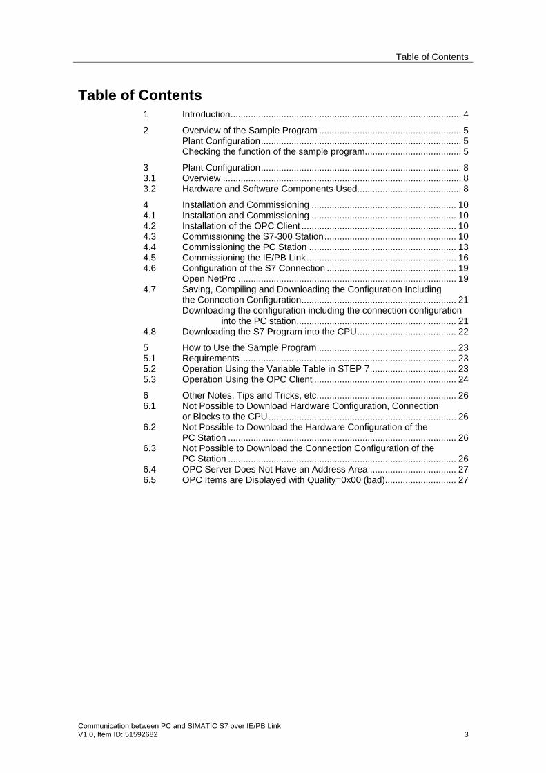
Table of Contents
Communication between PC and SIMATIC S7 over IE/PB Link V1.0, Item ID: 51592682 3
Table of Contents 1 Introduction........................................................................................... 4 2 Overview of the Sample Program ........................................................ 5
Plant Configuration............................................................................... 5 Checking the function of the sample program...................................... 5
3 Plant Configuration............................................................................... 8 3.1 Overview .............................................................................................. 8 3.2 Hardware and Software Components Used......................................... 8 4 Installation and Commissioning ......................................................... 10 4.1 Installation and Commissioning ......................................................... 10 4.2 Installation of the OPC Client ............................................................. 10 4.3 Commissioning the S7-300 Station.................................................... 10 4.4 Commissioning the PC Station .......................................................... 13 4.5 Commissioning the IE/PB Link........................................................... 16 4.6 Configuration of the S7 Connection ................................................... 19
Open NetPro ...................................................................................... 19 4.7 Saving, Compiling and Downloading the Configuration Including
the Connection Configuration............................................................. 21 Downloading the configuration including the connection configuration
into the PC station............................................................... 21 4.8 Downloading the S7 Program into the CPU....................................... 22 5 How to Use the Sample Program....................................................... 23 5.1 Requirements ..................................................................................... 23 5.2 Operation Using the Variable Table in STEP 7.................................. 23 5.3 Operation Using the OPC Client ........................................................ 24 6 Other Notes, Tips and Tricks, etc....................................................... 26 6.1 Not Possible to Download Hardware Configuration, Connection
or Blocks to the CPU.......................................................................... 26 6.2 Not Possible to Download the Hardware Configuration of the
PC Station .......................................................................................... 26 6.3 Not Possible to Download the Connection Configuration of the
PC Station .......................................................................................... 26 6.4 OPC Server Does Not Have an Address Area .................................. 27 6.5 OPC Items are Displayed with Quality=0x00 (bad)............................ 27
1 Introduction
4 Communication between PC and SIMATIC S7 over IE/PB Link
V1.0, Item ID: 51592682
1 Introduction This document supports you in creating user programs and configuration in the OPC environment.
How create user programs and the configuration are described step by step. The configurations used are created with the engineering tool SIMATIC STEP 7 or NCM PC.
This document serves as a reference work for configurations and communication with OPC components.
This document supports you to extend the components described and integrate them in your user program.
This document contains the following:
• An overview of the plant configuration.
• An example for the OPC client including documentation.
• A STEP 7 program including documentation.
• Operating and monitoring.
• Other Notes, Tips and Tricks, etc.
2 Overview of the Sample Program
Communication between PC and SIMATIC S7 over IE/PB Link V1.0, Item ID: 51592682 5
2 Overview of the Sample Program
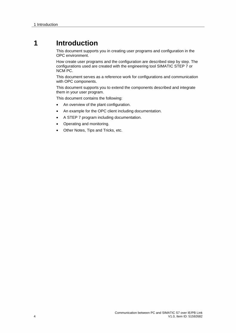
Plant Configuration
Figure 2-1
PC / SIMATIC Field PG with PROFIBUS CP
SIMATIC S7-300 or S7-400with Industrial Ethernet CP
Industrial Ethernet
IE/PB Link
PROFIBUS
OPC client /HMI
In this example the PC station is connected to the IE/PB Link over a PROFIBUS CP (CP5613) and a PROFIBUS bus cable.
A CP343-1 is used as communications processor in the S7-300. The S7-300 is connected to the IE/PB Link over the CP343-1 and an Industrial Ethernet cable.
The IE/PB Link functions as a gateway and links the PC station with the S7-300.
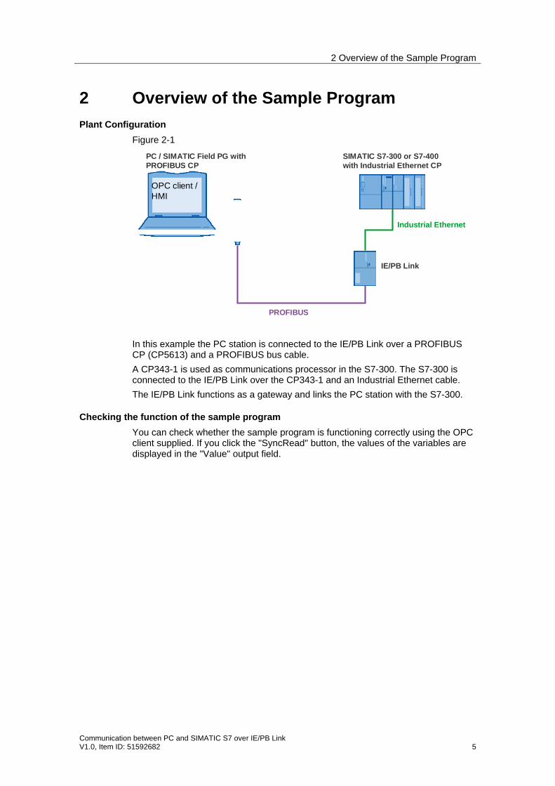
Checking the function of the sample program
You can check whether the sample program is functioning correctly using the OPC client supplied. If you click the "SyncRead" button, the values of the variables are displayed in the "Value" output field.
2 Overview of the Sample Program
6 Communication between PC and SIMATIC S7 over IE/PB Link
V1.0, Item ID: 51592682
Figure 2-2
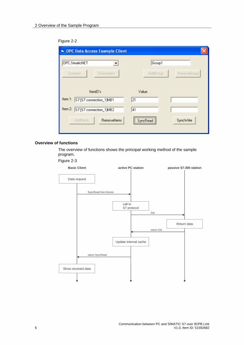
Overview of functions
The overview of functions shows the principal working method of the sample program.
Figure 2-3
Basic Client
Data request
call toS7 protocol
Update internal cache
active PC station passive S7-300 station
Return data
Show received data
SyncRead from Device
return SyncRead
Get
return Get
2 Overview of the Sample Program
Communication between PC and SIMATIC S7 over IE/PB Link V1.0, Item ID: 51592682 7
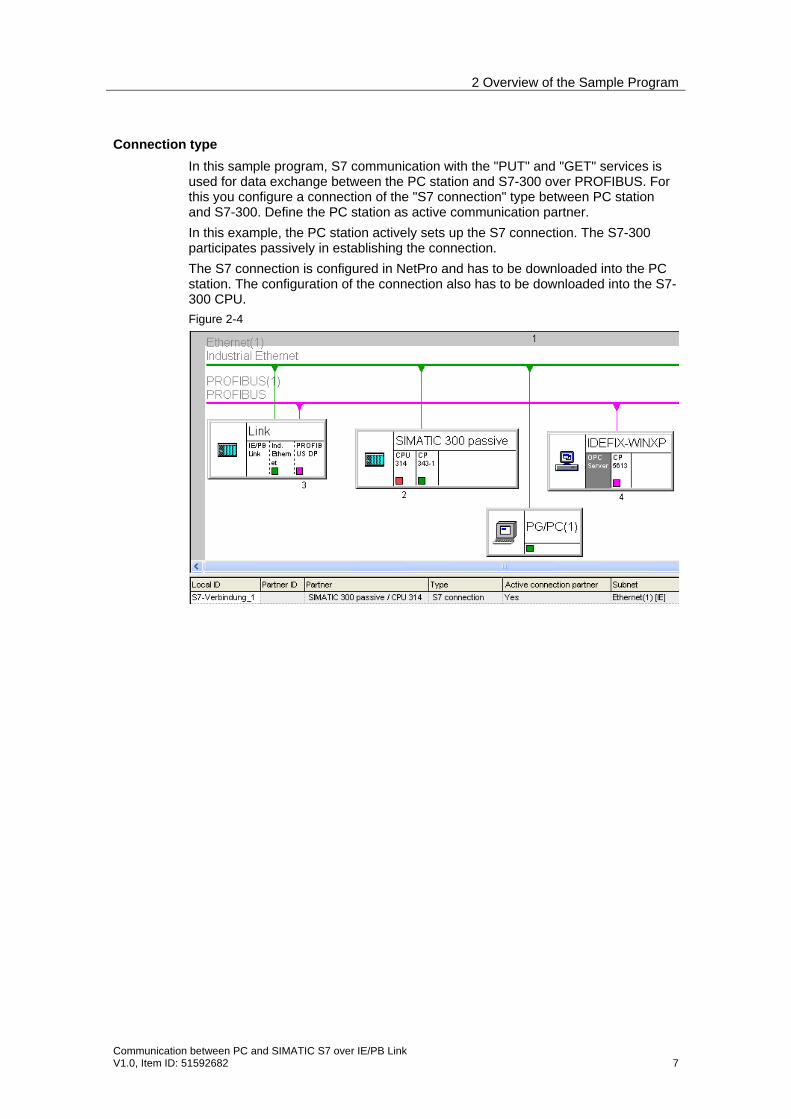
Connection type
In this sample program, S7 communication with the "PUT" and "GET" services is used for data exchange between the PC station and S7-300 over PROFIBUS. For this you configure a connection of the "S7 connection" type between PC station and S7-300. Define the PC station as active communication partner.
In this example, the PC station actively sets up the S7 connection. The S7-300 participates passively in establishing the connection.
The S7 connection is configured in NetPro and has to be downloaded into the PC station. The configuration of the connection also has to be downloaded into the S7-300 CPU.
Figure 2-4
3 Plant Configuration
8 Communication between PC and SIMATIC S7 over IE/PB Link
V1.0, Item ID: 51592682
3 Plant Configuration
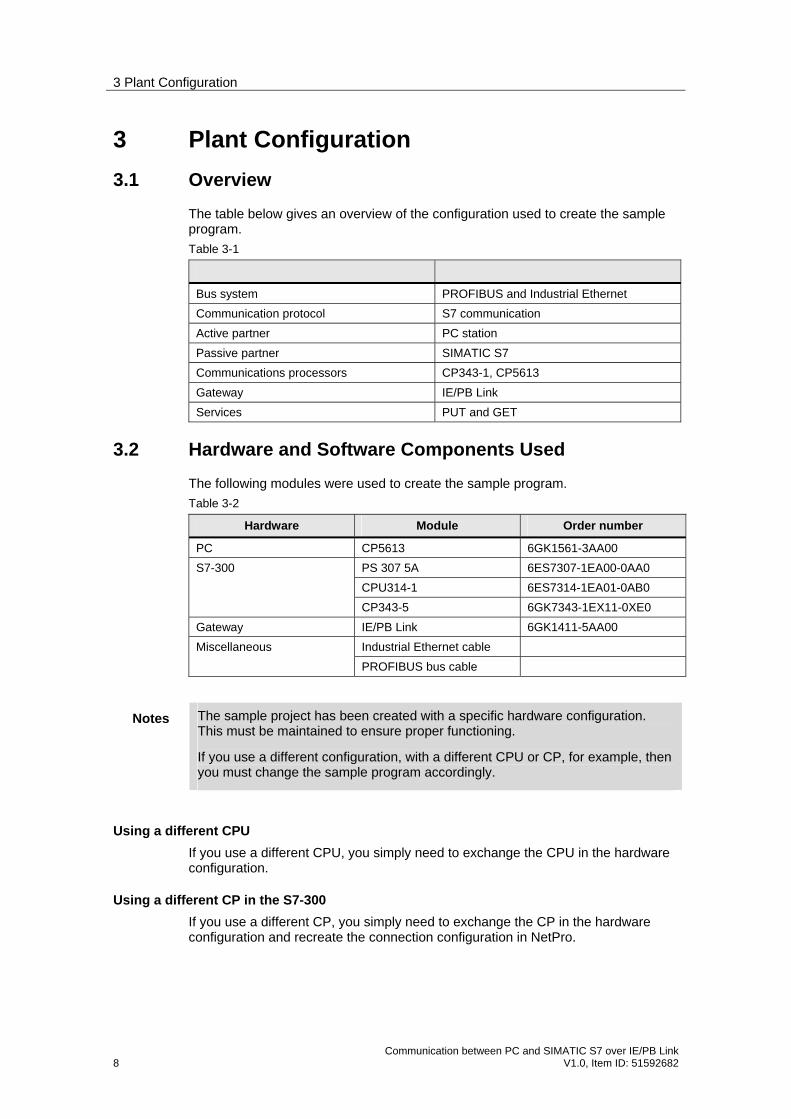
3.1 Overview
The table below gives an overview of the configuration used to create the sample program.
Table 3-1
Bus system PROFIBUS and Industrial Ethernet
Communication protocol S7 communication
Active partner PC station
Passive partner SIMATIC S7
Communications processors CP343-1, CP5613
Gateway IE/PB Link
Services PUT and GET
3.2 Hardware and Software Components Used
The following modules were used to create the sample program.
Table 3-2
Hardware Module Order number
PC CP5613 6GK1561-3AA00
PS 307 5A 6ES7307-1EA00-0AA0
CPU314-1 6ES7314-1EA01-0AB0
S7-300
CP343-5 6GK7343-1EX11-0XE0
Gateway IE/PB Link 6GK1411-5AA00
Industrial Ethernet cable Miscellaneous
PROFIBUS bus cable
Notes The sample project has been created with a specific hardware configuration. This must be maintained to ensure proper functioning.
If you use a different configuration, with a different CPU or CP, for example, then you must change the sample program accordingly.
Using a different CPU
If you use a different CPU, you simply need to exchange the CPU in the hardware configuration.
Using a different CP in the S7-300
If you use a different CP, you simply need to exchange the CP in the hardware configuration and recreate the connection configuration in NetPro.

3 Plant Configuration
Communication between PC and SIMATIC S7 over IE/PB Link V1.0, Item ID: 51592682 9
Using a different PROFIBUS CP in the PC
If you use a different PROFIBUS CP instead of the CP5613, you simply need to exchange the CP in the hardware configuration.
Software Components
• STEP 7 V5.2 or higher
• SIMATIC NET PC software V6.0 or higher
• NCM S7 PROFIBUS and Industrial Ethernet V5.2 or higher
• Microsoft Visual Basic V6.0 or higher

4 Installation and Commissioning
10 Communication between PC and SIMATIC S7 over IE/PB Link
V1.0, Item ID: 51592682
4 Installation and Commissioning
4.1 Installation and Commissioning
The sample program is a STEP 7 project that contains the complete hardware configuration including the user program of the S7-300 station and the configuration of the PC station.
The STEP 7 project is available for downloading as a ZIP file in the internet. Extract the "example_project.zip" file in a separate directory. The STEP 7 project then unpacks automatically with all the associated subdirectories. You can then use the SIMATIC Manager to open and process the extracted STEP 7 project.
4.2 Installation of the OPC Client
The OPC client is available for downloading as a ZIP file in the internet. Extract the "OPC_Client.zip" file in a separate directory. The sample program for the OPC client project is then automatically unpacked with all its subdirectories.
Double-click the "OPC-Client.exe" file to start the OPC client.
4.3 Commissioning the S7-300 Station
Configuration of the S7-300 station
Change the hardware configuration of the S7 station in the sample program so that it matches the hardware configuration in your plant.
Then, in the hardware configuration of the S7-300 station, you open the Properties dialog of the CP343-1.

4 Installation and Commissioning
Communication between PC and SIMATIC S7 over IE/PB Link V1.0, Item ID: 51592682 11
Figure 4-1
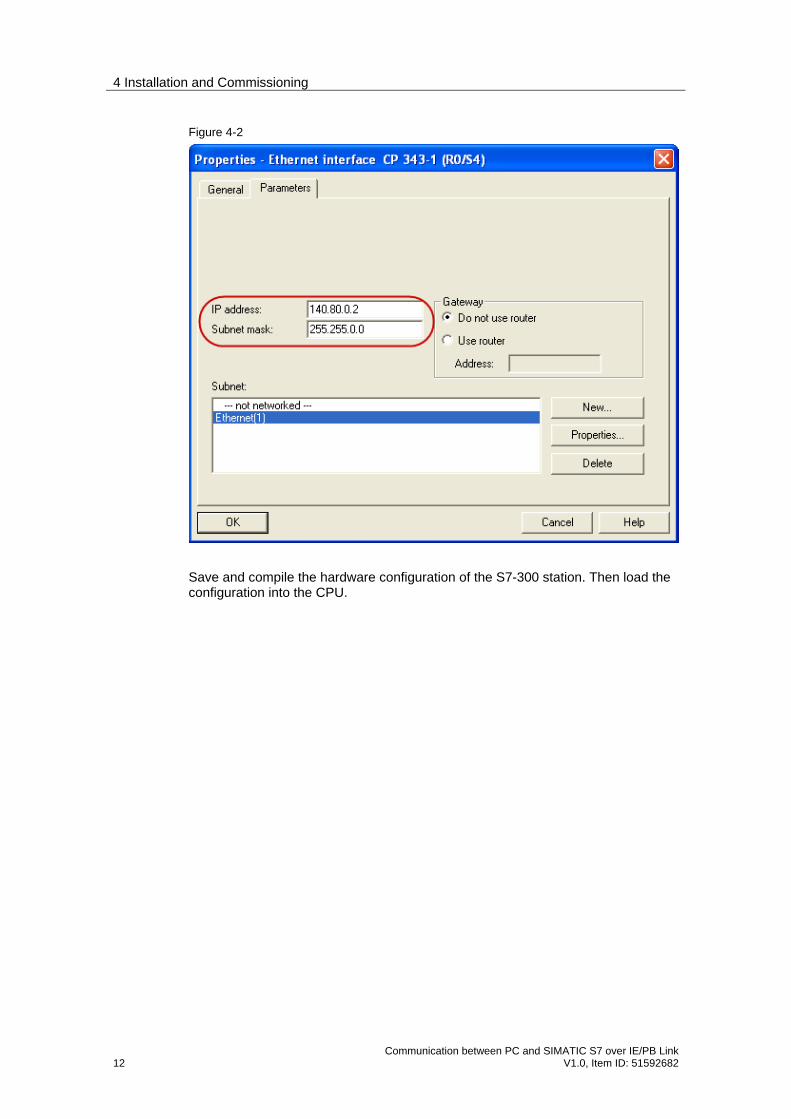
Click the "Properties..." button to open the "Properties - Ethernet interface CP 343-1" dialog. Select the "Parameters" tab and enter the IP address of the CP343-1.
4 Installation and Commissioning
12 Communication between PC and SIMATIC S7 over IE/PB Link
V1.0, Item ID: 51592682
Figure 4-2
Save and compile the hardware configuration of the S7-300 station. Then load the configuration into the CPU.
4 Installation and Commissioning
Communication between PC and SIMATIC S7 over IE/PB Link V1.0, Item ID: 51592682 13
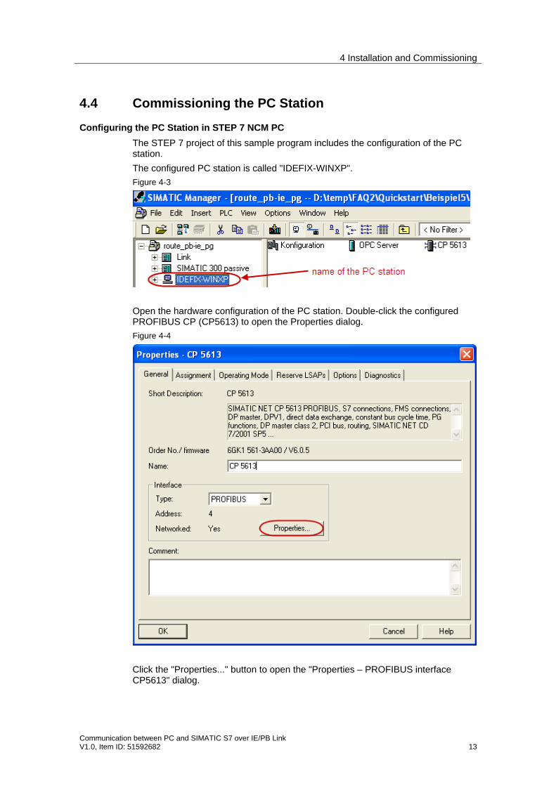
4.4 Commissioning the PC Station
Configuring the PC Station in STEP 7 NCM PC
The STEP 7 project of this sample program includes the configuration of the PC station.
The configured PC station is called "IDEFIX-WINXP".
Figure 4-3
Open the hardware configuration of the PC station. Double-click the configured PROFIBUS CP (CP5613) to open the Properties dialog.
Figure 4-4
Click the "Properties..." button to open the "Properties – PROFIBUS interface CP5613" dialog.
4 Installation and Commissioning
14 Communication between PC and SIMATIC S7 over IE/PB Link
V1.0, Item ID: 51592682
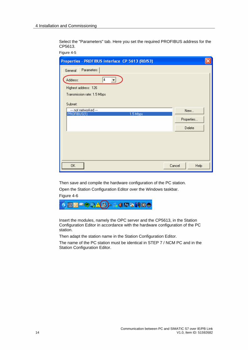
Select the "Parameters" tab. Here you set the required PROFIBUS address for the CP5613.
Figure 4-5
Then save and compile the hardware configuration of the PC station.
Open the Station Configuration Editor over the Windows taskbar.
Figure 4-6
Insert the modules, namely the OPC server and the CP5613, in the Station Configuration Editor in accordance with the hardware configuration of the PC station.
Then adapt the station name in the Station Configuration Editor.
The name of the PC station must be identical in STEP 7 / NCM PC and in the Station Configuration Editor.

4 Installation and Commissioning
Communication between PC and SIMATIC S7 over IE/PB Link V1.0, Item ID: 51592682 15
Figure 4-7
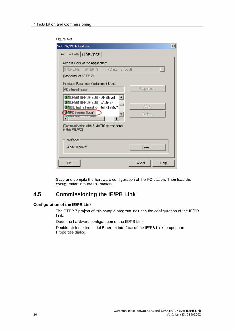
In the SIMATIC Manager, you select the menu "Tools Set PG/PC interface…". In the "Set PG/PC Interface" dialog you mark the interface "PC internal (local)". Apply the settings with "OK".
4 Installation and Commissioning
16 Communication between PC and SIMATIC S7 over IE/PB Link
V1.0, Item ID: 51592682
Figure 4-8
Save and compile the hardware configuration of the PC station. Then load the configuration into the PC station.
4.5 Commissioning the IE/PB Link
Configuration of the IE/PB Link
The STEP 7 project of this sample program includes the configuration of the IE/PB Link.
Open the hardware configuration of the IE/PB Link.
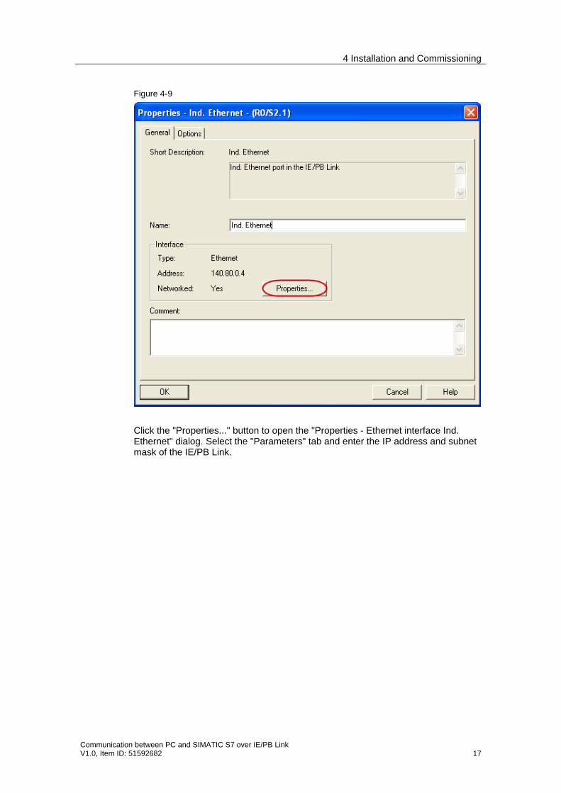
Double-click the Industrial Ethernet interface of the IE/PB Link to open the Properties dialog.
4 Installation and Commissioning
Communication between PC and SIMATIC S7 over IE/PB Link V1.0, Item ID: 51592682 17
Figure 4-9
Click the "Properties..." button to open the "Properties - Ethernet interface Ind. Ethernet" dialog. Select the "Parameters" tab and enter the IP address and subnet mask of the IE/PB Link.

4 Installation and Commissioning
18 Communication between PC and SIMATIC S7 over IE/PB Link
V1.0, Item ID: 51592682
Figure 4-10
Double-click the PROFIBUS interface of the IE/PB Link to open the Properties dialog.
Figure 4-11
4 Installation and Commissioning
Communication between PC and SIMATIC S7 over IE/PB Link V1.0, Item ID: 51592682 19
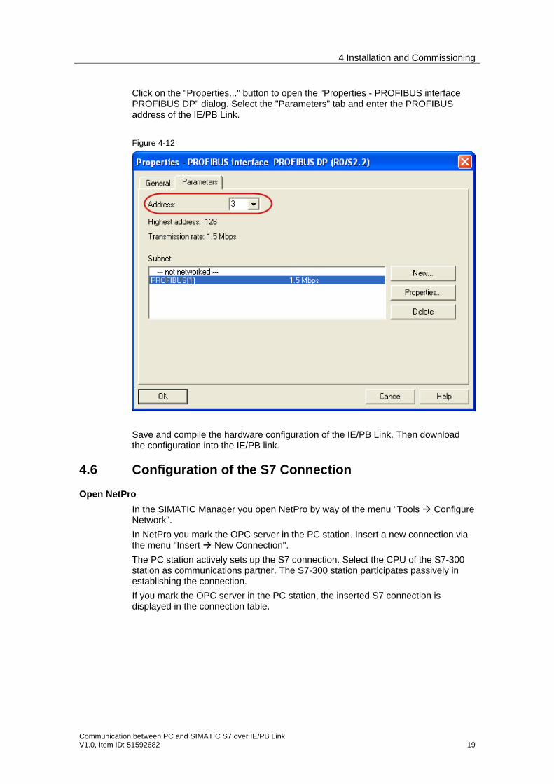
Click on the "Properties..." button to open the "Properties - PROFIBUS interface PROFIBUS DP" dialog. Select the "Parameters" tab and enter the PROFIBUS address of the IE/PB Link.
Figure 4-12
Save and compile the hardware configuration of the IE/PB Link. Then download the configuration into the IE/PB link.
4.6 Configuration of the S7 Connection
Open NetPro
In the SIMATIC Manager you open NetPro by way of the menu "Tools Configure Network".
In NetPro you mark the OPC server in the PC station. Insert a new connection via the menu "Insert New Connection".
The PC station actively sets up the S7 connection. Select the CPU of the S7-300 station as communications partner. The S7-300 station participates passively in establishing the connection.
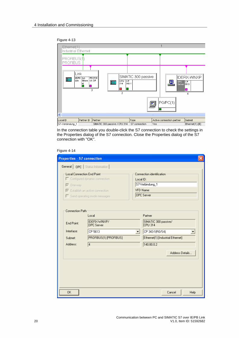
If you mark the OPC server in the PC station, the inserted S7 connection is displayed in the connection table.
4 Installation and Commissioning
20 Communication between PC and SIMATIC S7 over IE/PB Link
V1.0, Item ID: 51592682
Figure 4-13
In the connection table you double-click the S7 connection to check the settings in the Properties dialog of the S7 connection. Close the Properties dialog of the S7 connection with "OK".
Figure 4-14
4 Installation and Commissioning
Communication between PC and SIMATIC S7 over IE/PB Link V1.0, Item ID: 51592682 21
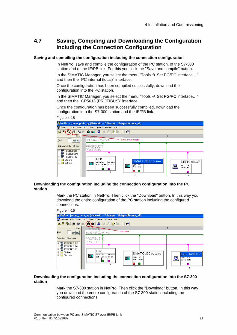
4.7 Saving, Compiling and Downloading the Configuration Including the Connection Configuration
Saving and compiling the configuration including the connection configuration
In NetPro, save and compile the configuration of the PC station, of the S7-300 station and of the IE/PB link. For this you click the "Save and compile" button.
In the SIMATIC Manager, you select the menu "Tools Set PG/PC interface…" and then the "PC internal (local)" interface.
Once the configuration has been compiled successfully, download the configuration into the PC station.
In the SIMATIC Manager, you select the menu "Tools Set PG/PC interface…" and then the "CP5613 (PROFIBUS)" interface.
Once the configuration has been successfully compiled, download the configuration into the S7-300 station and the IE/PB link.
Figure 4-15
Downloading the configuration including the connection configuration into the PC station
Mark the PC station in NetPro. Then click the "Download" button. In this way you download the entire configuration of the PC station including the configured connections.
Figure 4-16
Downloading the configuration including the connection configuration into the S7-300 station
Mark the S7-300 station in NetPro. Then click the "Download" button. In this way you download the entire configuration of the S7-300 station including the configured connections.
4 Installation and Commissioning
22 Communication between PC and SIMATIC S7 over IE/PB Link
V1.0, Item ID: 51592682
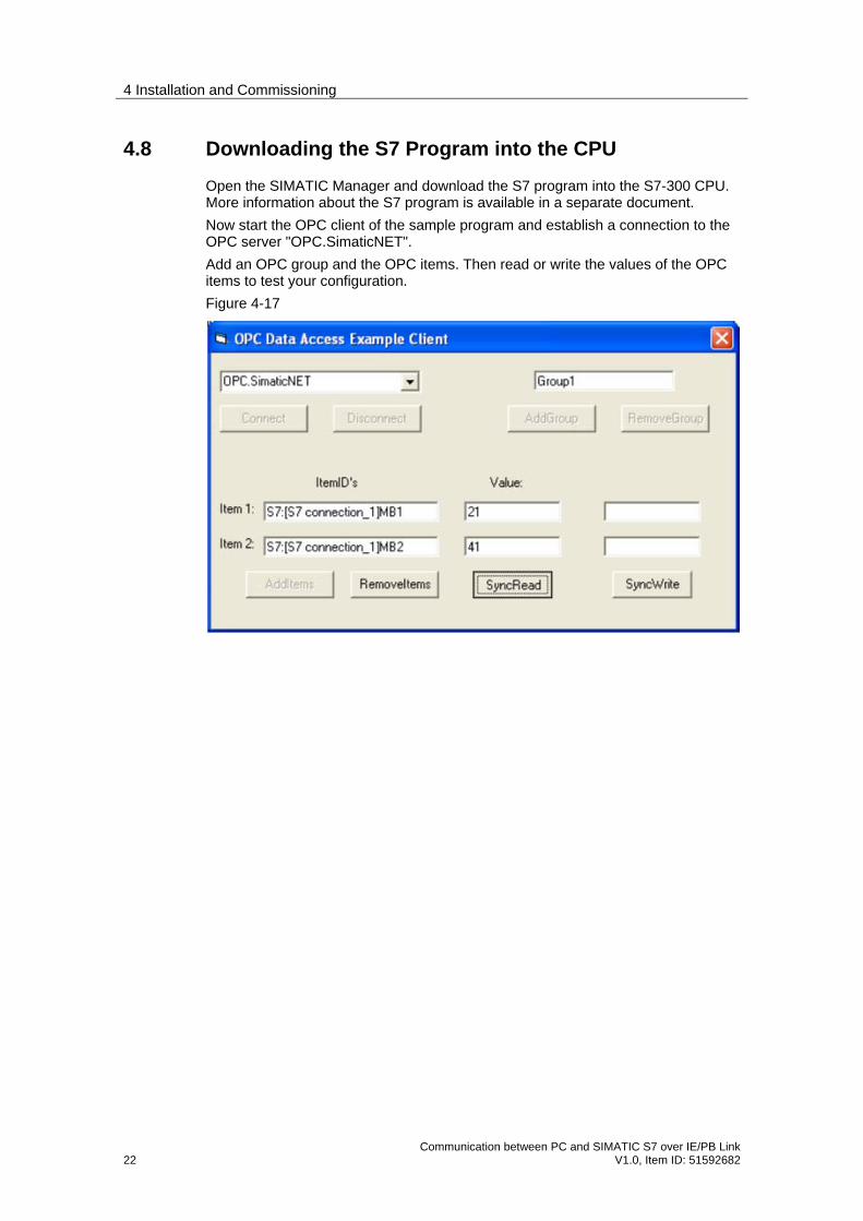
4.8 Downloading the S7 Program into the CPU
Open the SIMATIC Manager and download the S7 program into the S7-300 CPU. More information about the S7 program is available in a separate document.
Now start the OPC client of the sample program and establish a connection to the OPC server "OPC.SimaticNET".
Add an OPC group and the OPC items. Then read or write the values of the OPC items to test your configuration.
Figure 4-17
5 How to Use the Sample Program
Communication between PC and SIMATIC S7 over IE/PB Link V1.0, Item ID: 51592682 23
5 How to Use the Sample Program You operate the sample program
• using the variable table which is supplied with the S7-300 user program, or
• using the supplied OPC client.
5.1 Requirements
S7-300 station
In the S7-300 station the sample program is operated using the supplied variable table.
The requirements for monitoring and controlling variables must be fulfilled:
• An online connection to the CPU must be established.
• The "Monitor variables" function must be enabled.
• The control values must be marked as valid.
If the conditions mentioned above are met, the variable table displays the specified memory areas.
PC station
On the PC station the data is read over the OPC server from the S7-300 CPU or written to the S7-300 CPU. The data is monitored and controlled in the supplied OPC client.
The requirements below must be fulfilled for this in the supplied OPC client:
• The PC station must be completely configured, meaning that the CP is in the configured mode.
• The CP in the PC station and the CP of the S7-300 must be networked over Ethernet and PROFIBUS.
If the above-mentioned conditions are met and the sample program is working correctly, then you click the "SyncRead" button to display the variables in the OPC client.
5.2 Operation Using the Variable Table in STEP 7
Monitoring is possible using the variable table which is supplied in the example. How to use it is described step by step below.
Table 5-1
No. Description
1. Start the SIMATIC Manager with the Windows START menu SIMATIC SIMATIC Manager.
2. In the SIMATIC Manager you open the STEP 7 project "route_pb".
3. In the project window you navigate to the block folder of the S7 program of the S7-300 station.

5 How to Use the Sample Program
24 Communication between PC and SIMATIC S7 over IE/PB Link
V1.0, Item ID: 51592682
No. Description
4. Double-click the "VAT1" variable table in the Blocks folder.
5. In the variable table establish a connection to the S7-300 by means of the menu "Target system Establish connection to Configured CPU".
5.3 Operation Using the OPC Client
On the PC station the sample program is operated using the supplied OPC client. A detailed description of the OPC client is available in a separate document.
Table 5-2
No. Description
1. Double-click the "OPC-Client.exe" program to start the OPC client.
2. Select the OPC server "OPC.SimaticNET" and click the "Connect" button to establish a connection to the OPC server.
3. Enter a name for the OPC group and any comment and click the "AddGroup" button to create an OPC group.
4. Enter the names of the OPC items and click the "AddItems" button to create the OPC items.
5. Click the "SyncRead" button to display the values of the variables in the "Value" output field.
5 How to Use the Sample Program
Communication between PC and SIMATIC S7 over IE/PB Link V1.0, Item ID: 51592682 25
No. Description
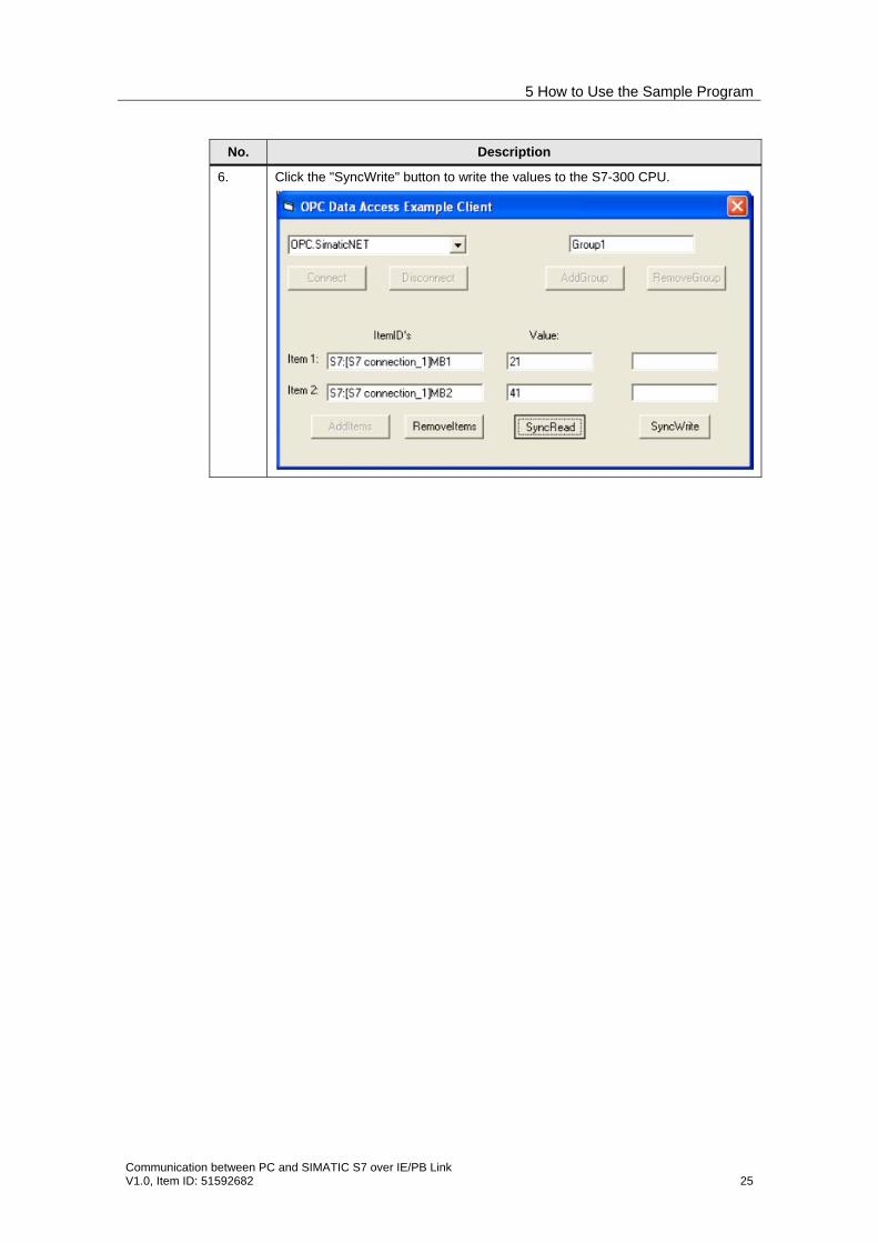
6. Click the "SyncWrite" button to write the values to the S7-300 CPU.
6 Other Notes, Tips and Tricks, etc.
26 Communication between PC and SIMATIC S7 over IE/PB Link
V1.0, Item ID: 51592682
6 Other Notes, Tips and Tricks, etc. This chapter gives you more notes, tips and tricks for the commissioning and working of the sample program.
6.1 Not Possible to Download Hardware Configuration, Connection or Blocks to the CPU
If it is not possible to download the hardware configuration, connection or blocks to the CPU, then make the following checks and take the following measures to remedy the situation.
• Check that the PROFIBUS cable is connected to the CP5613 of the PC station and the PROFIBUS interface of the IE/PB Link.
• Check that the Industrial Ethernet cable is connected to the Industrial Ethernet interface of the communications processor in the S7 station and to the Industrial Ethernet interface of the IE/PB Link.
• Check the settings in "Set the PG/PC interface". The PROFIBUS CP, CP5613 (PROFIBUS), for example, must be assigned to the access point of the "S7ONLINE (STEP 7)" application.
• Open the hardware configuration. The hardware configuration in the STEP 7 project must match the configuration of the S7-300 or S7-400 station.
• Do a complete reset of the S7-300 or S7-400 CPU.
6.2 Not Possible to Download the Hardware Configuration of the PC Station
If it is not possible to download the hardware configuration of the PC station, then check whether the hardware configuration matches the settings that are to be downloaded.
• In the hardware configuration use the menu "File Check consistency" to check the settings and clear any errors displayed.
• Following a failed download attempt, open the station configuration editor and rectify the faults which are displayed there in the "Diagnostics" tab (such as "incorrect subnet mask").
6.3 Not Possible to Download the Connection Configuration of the PC Station
The OPC server can only be operated if the connection configuration in NetPro has been successfully downloaded to the PC station after "Save and Compile".
If it is not possible to download the connection configuration of the PC station over NetPro, then make the following checks and take the following measures to remedy the situation.
• Check whether errors are displayed during "Save and compile" in NetPro. Rectify all the errors which are displayed for the PC station during "Save and Compile".
6 Other Notes, Tips and Tricks, etc.
Communication between PC and SIMATIC S7 over IE/PB Link V1.0, Item ID: 51592682 27
• Also rectify any errors displayed in the "Diagnostics" tab of the station configuration editor. Note If errors are displayed in the station configuration editor, this is indicated by a flashing yellow exclamation mark in the Windows status bar.
• Download the PC station again.
6.4 OPC Server Does Not Have an Address Area
When browsing the OPC server "OPC.SimaticNET" using the OPC Scout, nothing is displayed (a blank window is displayed in the OPC Navigator) or the configured connection is not displayed.
The address area of the OPC server is created when you download the hardware configuration and the connection configuration of the PC station. The settings are applied only when you start the OPC server. Ensure that the OPC server is restarted after you have changed the configuration. For this you must log off (disconnect) all the OPC clients from the OPC server.
In "Set PC station", check whether the required protocols are enabled.
6.5 OPC Items are Displayed with Quality=0x00 (bad)
In the OPC client the quality of the variables read (OPC items) has the value "0x00" (bad).
During reading to an OPC server, the value of the variables is transferred, along with the quality of this value. The value should only be used when the quality has the value "0xC0" (good).
The property Quality=0x00 (bad) means that the read variable (OPC item) cannot be reached temporarily or not at all (because of a disconnected connection like CP in STOP, for example).