SIM-KNX - tapko.de · EN 50090-2-2:1996 + Corrigendum 1997 EN 55022:1998 + A1:200 + A2:2003 EN...
71
SIM-KNX 27.02.2008 1 / 71 SERIAL INTERFACE MODULE KNX SIM-KNX DOCUMENTATION V 1.3 Author: Klaus Adler Last Modification: 01.10.2007
Transcript of SIM-KNX - tapko.de · EN 50090-2-2:1996 + Corrigendum 1997 EN 55022:1998 + A1:200 + A2:2003 EN...

SIM-KNX
27.02.2008 1 / 71
SERIAL INTERFACE MODULE KNX SIM-KNX
DOCUMENTATION V 1.3
Author: Klaus Adler Last Modification: 01.10.2007

SIM-KNX
2 / 71 27.02.2008
© 2005-2007 TAPKO Technologies GmbH Yorckstr. 22, 93049 Regensburg, Germany The data contained herein are subject to change without notice. Tapko does not warrant for correctness or completeness of the document. The reproduction, transmission or use of this document or it’s contents is not permitted without written authority. All rights reserved.

SIM-KNXContents
27.02.2008 3 / 71
1 CONTENTS 1 Contents............................................................................................................................. 3 2 Index .................................................................................................................................. 5
2.1 API ............................................................................................................................. 5 3 General .............................................................................................................................. 6
3.1 General Features......................................................................................................... 7 3.1.1 Resources in raw / interoperability mode........................................................................................ 8
3.2 Reading this documentation ....................................................................................... 9 3.2.1 Command Description..................................................................................................................... 9
4 Hardware ........................................................................................................................ 10 4.1 Block Diagram ......................................................................................................... 10 4.2 Pin – Description...................................................................................................... 11 4.3 General Device Specification................................................................................... 12
4.3.1 Absolute Maximum Ratings.......................................................................................................... 12 4.3.2 Recommended Operating Conditions............................................................................................ 12 4.3.3 Tested EMC Levels....................................................................................................................... 12
5 Software........................................................................................................................... 13 5.1 Block Diagram ......................................................................................................... 13 5.2 Introduction .............................................................................................................. 14
5.2.1 Operation with Communication Objects (Raw / interoperability mode)....................................... 14 5.2.2 Operation without Communication Objects (Transparent mode).................................................. 19 5.2.3 Device information........................................................................................................................ 21
6 Serial protocol................................................................................................................. 22 6.1 Settings ..................................................................................................................... 22
6.1.1 Change the Settings:...................................................................................................................... 22 Syntax................................................................................................................................... 23
6.1.2 General Syntax (command based)................................................................................................. 23 6.1.3 Strings from SIM-KNX................................................................................................................. 24 6.1.4 Values............................................................................................................................................ 25
6.2 Command overview ................................................................................................. 26 6.2.1 General .......................................................................................................................................... 26 6.2.2 Commands in RAW-MODE and NTEROPERABILITY-MODE ................................................ 26 6.2.3 Commands in TRANSPARENT-MODE...................................................................................... 27
6.3 Command reference (General) ................................................................................. 28 6.3.1 Accessing interface objects ........................................................................................................... 28 6.3.2 Device settings .............................................................................................................................. 29 6.3.3 Parameter ...................................................................................................................................... 33
6.4 Command reference (raw / interoperability mode) .................................................. 34 6.4.1 Configuration ................................................................................................................................ 34 6.4.2 Accessing group communication objects (raw mode)................................................................... 35 6.4.3 Accessing group communication objects (interoperability mode) ................................................ 36 6.4.4 Accessing group communication objects (raw / interoperability mode) ....................................... 37 6.4.5 Configure group communication objects ...................................................................................... 40 6.4.6 Indications ..................................................................................................................................... 52
6.5 Command Reference (Transparent mode) ............................................................... 53 6.6 Error Codes .............................................................................................................. 58
7 Implemented Application Interface Objects................................................................ 60 7.1 Object Index: 5 ......................................................................................................... 60
8 ETS .................................................................................................................................. 63 8.1 Group Objects .......................................................................................................... 63 8.2 Parameter.................................................................................................................. 63
9 Examples how to use SIM-KNX ................................................................................... 65 9.1 Using SIM-KNX without ETS-database entry......................................................... 65

SIM-KNX Contents
4 / 71 27.02.2008
9.2 Using SIM-KNX with ETS- database entry............................................................. 65 9.3 Using SIM-KNX in Transparent mode .................................................................... 65
10 Mechanical Specifications.......................................................................................... 66 10.1 Straight connector (-S option) .................................................................................. 66 10.2 Right angle connector (-RA option)........................................................................ 67
11 Ordering details.......................................................................................................... 68 12 Glossary....................................................................................................................... 69 13 Further Documentation ............................................................................................. 70

SIM-KNXIndex
27.02.2008 5 / 71
2 INDEX 2.1 API
cvg.................................................................... 26, 36 cvs .................................................................... 26, 36 dag.................................................................... 26, 29 das .................................................................... 26, 29 dpg ................................................................... 26, 30 dps.................................................................... 26, 30 dr ...................................................................... 26, 31 dsg.................................................................... 26, 31 dts..................................................................... 26, 27 dus.................................................................... 26, 34 dvg ................................................................... 26, 32 gcg.................................................................... 26, 39 gci .......................................................................... 32 gtg .................................................................... 26, 39 gug ................................................................... 26, 39 gui .................................................................... 26, 52 idg .................................................................... 26, 28 ids..................................................................... 26, 28 ocg.................................................................... 26, 43 ocs .................................................................... 26, 42 odg ................................................................... 26, 35 odr .................................................................... 26, 37
ods.................................................................... 26, 35 odt .................................................................... 26, 37 ofg.................................................................... 26, 37 oga ................................................................... 26, 40 ogd ................................................................... 26, 41 ogg ................................................................... 26, 41 ogs.................................................................... 26, 40 oui .................................................................... 26, 52 pdg ................................................................... 26, 33 tdc .................................................................... 27, 56 tdi ..................................................................... 27, 55 tdn .................................................................... 27, 57 tds..................................................................... 27, 53 tec..................................................................... 27, 56 tei ..................................................................... 27, 55 ten .................................................................... 27, 57 tes..................................................................... 27, 54 trc ..................................................................... 27, 55 tri...................................................................... 27, 54 trn..................................................................... 27, 56 trs ........................................................................... 54

SIM-KNX General
6 / 71 27.02.2008
3 GENERAL Since the EIB system has evolved to KNX system, we also changed the name of our product from SIM-EIB to SIM-KNX. There is no other substantial change. The SIM-KNX is an easy to use serial interface to the KNX. The access to the KNX is realized as an serial ASCII protocol. The SIM-KNX consists of an micro controller and galvanic isolation and contains the complete certificated KNX communication system and conversion to the data formats used on KNX. This module is designed to connect controller or other devices to the KNX. Due to its design it is also applicable for small and mid range quantities. The SIM-KNX can be used in several different modes:
- Raw mode In this mode the SIM-KNX transfers the data transparent from the serial interface to KNX and vice versa. Here the transmission of the data are triggered complete by the serial interface. The configuration of this mode is normally done via the serial interface – no external tool is required.
- Interoperability mode In this mode the SIM-KNX converts the data, which are transmitted from the serial interface to the KNX in an KNX conform data format. The transmission of the data are controlled by the SIM-KNX depending on the configuration. In additional for a part of the group communication objects advanced transmit conditions are available. These are cyclic sending and a integrated threshold switch. The configuration of this mode can be done via ETS or serial interface.
- Transparent mode Transparent mode enables receiving from, and sending to all group addresses without any filtering. There are no data type limitations for sending. This mode is suitable for tracing the group oriented message traffic.

SIM-KNXGeneral
27.02.2008 7 / 71
3.1 GENERAL FEATURES Application Interface - serial asynchronous interface - 3V to 5V interface - 3- wire interface - ASCII protocol - Configurable baud rate and transmission parameter - Access to KNX group communication objects (runtime communication) - Access to KNX interface objects (configuration) - Configurable indication when group communication value was received KNX features (raw + interoperability mode) - device model 0701 - mechanism for configuration via KNX integrated - read requests from KNX serviced internally in the module - Two different numbers of group objects: 128 or 254 KNX group communication objects (raw mode) - transparent transmission of the group communication object data - data conversion not active - telegram generation triggered via serial interface - configuration via serial interface KNX group communication objects (interoperability mode) - support of EIB / KNX data types (EIS / DPT) - data conversion for group object values (e.g. temperature -> EIS5) - configurable send conditions for all group communication objects - configuration via ETS database entry or serial interface - indication when data received, value changed, positive/negative edges (EIS 1) - cyclic (time configurable between 3 to 255 sec, 3 to 255 minutes) - advanced transmit conditions
· send on value difference · receive timeout on received telegrams · integrated threshold switch · triggers another group communication object when threshold value was passed
Transparent mode - receiving of all group oriented messages - no filtering of messages - sending on all group addresses - no restriction of a specific data type to a specific group address for sending - not needed protocol oriented information is removed - also suitable for tracing and logging of messages
SIM-KNX General
8 / 71 27.02.2008
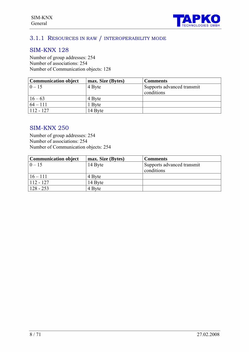
3.1.1 RESOURCES IN RAW / INTEROPERABILITY MODE
SIM-KNX 128 Number of group addresses: 254 Number of associations: 254 Number of Communication objects: 128 Communication object max. Size (Bytes) Comments 0 – 15 4 Byte Supports advanced transmit
conditions 16 – 63 4 Byte 64 – 111 1 Byte 112 - 127 14 Byte
SIM-KNX 250 Number of group addresses: 254 Number of associations: 254 Number of Communication objects: 254 Communication object max. Size (Bytes) Comments 0 – 15 14 Byte Supports advanced transmit
conditions 16 – 111 4 Byte 112 - 127 14 Byte 128 - 253 4 Byte

SIM-KNXGeneral
27.02.2008 9 / 71
3.2 READING THIS DOCUMENTATION
3.2.1 COMMAND DESCRIPTION
GGeett OObbjjeecctt DDaattaa
odg (objectNr)
returns the data of a group communication object inside the SIM-KNX. This command deletes the appropriate update-flag. Depending on the object length the data returned can be from 1 byte up to 14 byte. Parameter objectNr Number of the group communication objects
which is manipulated allowed: single values
Return values data Data, which are read from the group communication object. Example odg (0)
<odg (0)> $01
Title
Command structure
Description
Parameter Description
returned value
Example: odg (0): Command sent to SIM-KNX <odg (0)> $01: returned form SIM-KNX
Figure 1: command description

SIM-KNX Hardware
10 / 71 27.02.2008
4 HARDWARE 4.1 BLOCK DIAGRAM
SIM-KNX
KNX-Interface (TPUART)
Micro-controller
galvanic Isolationand serial
line driver
KNX
Programmbutton / LED
serial Interface
Figure 2 Block diagram of SIM-KNX
Controler with
User-Application
LEDKey
Isolation
3LE
D
Key
2
VCC
GND
TxDRxDRxD
GND
TxDVCC_E
8
567
Bus-
Bus+
1
4
Bus -
Bus+
SIM - KNX
Figure 3: Example, how to use SIM-KNX

SIM-KNXHardware
27.02.2008 11 / 71
4.2 PIN – DESCRIPTION PinNr. Pin Description 1 Bus- Negative bus pin 4 Bus+ Positive bus pin 2 Key Connector for KNX programming button 3 LED Connector for KNX programming LED 8 GND Ground 7 RXD Input of the serial interface 6 TXD Output of the serial interface 5 VCC_E Power supply input for the galvanic isolated part

SIM-KNX Hardware
12 / 71 27.02.2008
4.3 GENERAL DEVICE SPECIFICATION
4.3.1 ABSOLUTE MAXIMUM RATINGS All voltages are referring to GND. Currents are declared positive in case of flowing into pin. Symbol Parameter Min Type Max Unit VISO Isolation Voltage 4000 V VBus Bus Voltage (Bus+ to Bus-) -45 45 V VVCC supply voltage -0,5 5,5 V VRXD voltage on pin RXD -0,5 5,5 /
VVCC V
Storage temperature -40 85 °C maximum power dissipation 1 W
4.3.2 RECOMMENDED OPERATING CONDITIONS Symbol Parameter Min Type Max Unit VBus Bus Voltage (Bus+ to Bus-) 20 28 33 V VVCC supply voltage 3 5 V VRXD voltage on pin RXD -0,5 VVCC V Operating temperature -25 85 °C IBus Bus power consumption 5 mA IRXD 7 mA VRXD(low) 0,7 V VRXD(high) ITXD < 100µA VVCC –1,5 V ITXD with VVCC=5,5V 0,1 0,8 mA VTXD(low) 0 0,7 V
ITXD < 100µA VVCC –0,8 VVCC V VTXD(high) ITXD < 50µA VVCC –0,4 VVCC V
IVCC with VVCC=5,5V 1,5 mA ILED 2,6 mA IKEY 33 50 µA
4.3.3 TESTED EMC LEVELS All EMC tests are done together with an evaluation board. KNX Standard: Volume 4; Part 2:2002 EN 50090-2-2:1996 + Corrigendum 1997 EN 55022:1998 + A1:200 + A2:2003 EN 61000-3-2: 2000, EN 61000-3-3: 1995 + A1: 2001 EN 50090-2-2: 1996 + Corrigendum 1997 EN 6100-4-2: 1995 + A1:1998 + A2: 2001 EN 6100-4-3: 2002 + A1:2002 EN 6100-4-4: 1995 + A1:2001 + A2: 2001 EN 6100-4-5: 1995 + A1:2001 EN 6100-4-6: 1996 + A1:2001 EN 6100-4-8: 1993 EN 6100-4-11: 1994 It is thus fully compliant with the EMC requirements for CE marking.

SIM-KNXSoftware
27.02.2008 13 / 71
5 SOFTWARE 5.1 BLOCK DIAGRAM
SIM-KNX
KNX-Communication System
Application
Group Communication Objectss
Raw mode interoperability mode
serial Interface / Protocol evaluation
Data conversion
Figure 4: Structure of software

SIM-KNX Software
14 / 71 27.02.2008
5.2 INTRODUCTION There are two general ways of operation for the SIM-KNX.
- In the first way of operation the SIM-KNX behaves like a normal divice. It has its own physical address, an address table, communication objects and a complete device management.
- In the second way of operation the SIM-KNX has an additional bypass activated in the lower layers for group oriented communication. Thus the complete group oriented traffic is routed to the serial interface without any communication objects or any filtering.
5.2.1 OPERATION WITH COMMUNICATION OBJECTS (RAW / INTEROPERABILITY MODE)
The runtime communication on EIB / KNX is done via the communication objects. SIM-KNX has a set of communication objects in its memory. It receives the EIB / KNX group telegrams and stores the values of the associated group addresses in the corresponding communication objects. So SIM-KNX has always the latest value of the communication objects. This values can be read via the serial interface. In the other direction the value is transferred via the serial interface to the communication objects in SIM-KNX and SIM-KNX sends than the value depending on the send conditions to the bus. It is also possible to read a value from KNX. Therefore SIM-KNX can be triggered via the serial interface to send a read request to the bus. When an value read was received from KNX, the response is handled inside SIM-KNX, the stored values of the communication objects are then sent to the bus. SIM-KNX can also create an indication on the serial interface, when an object value was received or changed. SIM-KNX has two modes to exchange data via the communication objects, which can be selected for each communication object independent.
- RAW-mode - Interoperability mode
RAW-MODE In Raw mode the raw data is exchanged via the serial interface with SIM-KNX. In this mode SIM-KNX has no knowledge about the format and semantics of the exchanged data. Only the size of the communication object is known by SIM-KNX. This mode is normally used, when SIM-KNX is configured via serial interface. To configure the communication object in Raw mode you set the DPT in the command ocs to 0 and configure the size of the object via the parameter object type.
INTEROPERABILITY-MODE In Interoperability mode SIM-KNX has not only the size of the communication objects but also the type of the data point. This data point types (DPT) are standardized in KNX to guarantee interworking of the devices. The DPT definition contains the format and also the usage of the various data point types. In interoperability mode SIM-KNX supports a wide range of data point types. The complete list of DPTs is available at KNX Association.

SIM-KNXSoftware
27.02.2008 15 / 71
To configure the communication object in interoperability mode set the DPT in the command ocs. The parameter object type is than ignored be SIM-KNX.
FEATURES OF THE COMMUNICATION OBJECTS The configuration objects of SIM-KNX haves the following features: Standard features of communication objects as defined in the device model:
- Enable the transmission and reception of communication object value - Enable receiving of the value read from the bus - setting priorities
Specific features of SIM-KNX for all communication objects - format conversion in interoperability mode - object values can be sent to the bus
o when value from serial interface was received o when value from serial interface was changed o for EIS 1: on change on positive and / or negative edge o cyclic
- indication to serial interface can be generated o when a value was received from EIBKNX o when the value, which was received from KNXEIB was changed o when the receive timeout was elapsed
Advanced send transmit conditions for SIM-KNX, available only for the first block of communication objects.
- configurable only with ETS, - send on bus, when the value was changed for a certain value - Threshold switch
o triggers another communication object when threshold value was passed. The configuration of SIM-KNX is stored in nonvolatile memory. The configuration is not changed with a restart or power down. The values of the communication objects are stored in volatile memory. The values are deleted with a restart or power down of SIM-KNX.
TRANSFERRING COMMUNICATION OBJECT DATA VIA SERIAL INTERFACE The data of the communication object are set via the command
- ods in raw mode - ovs in interoperability mode
To receive the data of the communication objects the commands are: - odg in raw mode - ovg in interoperability mode
The format in which the data are transferred in raw mode are hex bytes. In interoperability mode the data format depends on the used data point type and can be for example a simple number, a float value or a string. The data format are described in the list of data point types.

SIM-KNX Software
16 / 71 27.02.2008
DATAPOINT TYPES The Datapoint types and their usage are standardized inside KONNEX / KNX. Definitions of the datapoint types can be found in KNX handbook “Volume 3 / Part 7 / Chapter 2: Datapoint Types”, available from the KNX-website (see also : Page 13 Further Documentation) or on the CD of the SIM-KNX evaluation kit. The following DPT are mainly used:
DPT1 (1BIT) ON / OFF This DPT is used to switch on (1) or off(2) lights, relays,… It is also used to move blinds up (0) and down (1). Further usages as enable / disable are defined. On the serial interface of SIM-KNX the data are transferred as a single value 0 or 1.
DPT3 DIMMING CONTROL This DPT is defined as a 4 bit communication object. The values of this DPT are interpreted as follow: C VVV Data format of SIM-KNX: C {0,1}: control (0=off, 1=on) V {0 .. 7}: value
DPT9 TEMPERATURE This DPT is in KNX defined as a 16bit floating point value. Data format of SIM-KNX (interoperability mode): single value Due to conversion of the value, it may happen that the value you read back from SIM-KNX is not exactly the one you write.
DPT5 SCALING This DPT is used for absolute dimming, absolute blind position, value of valves, … On the bus the value is transmitted as a 1byte value(0..255). 100% is coded as 255. In interoperability mode the value is transmitted as a single value in the range of 0 to 100 ($64). Due to conversion of the value, it may happen that the value you read back from SIM-KNX is not exactly the one you write.
DPT10 TIME On KNX the time is transmitted as a 3byte value. Dataformat of SIM-KNX: SIM-KNX expects 4 values in the following format: w h m s
DPT11 DATE This DPT is similar to DPT10 The following interpretation are carried out by SIM-KNX: If Octet3 contains value ≥ 90 : interpret as 20th century If Octet 3 contains value < 90: interpret as 21st century This format covers the range 1990 to 2089. SIM-KNX expects 3 values in the following format: d m y

SIM-KNXSoftware
27.02.2008 17 / 71
CONFIGURATION OF THE COMMUNICATION OBJECTS The configuration of the communication can be done via
- serial interface or - application specific ETS database entry
CONFIGURATION OF THE COMMUNICATION OBJECTS VIA SERIAL INTERFACE The configuration of the communication objects are split in several parts:
- assignment of group addresses - setting the communication parameter - configuring the indications
SETTING THE GROUP ADDRESSES The group addresses for the communication objects are configured via the commands:
- ogs: set sending group address - oga: add group address - ogd: delete group addresses
Each communication object can be associated with several group addresses. One group address is always the sending group address. It is used to send the object values on the bus. All other group addresses are used to receive object values. Receiving group addresses are set via the command oga (e.g. oga (1) 1/0/0). The group address can be transferred as hex number ($1000) or in ETS format (2/0/0). The sending group address is set via ogs. If there was one sending group address, before sending this command, the old sending group address is still active as receiving group address. If the sending group address is deleted or no group address was marked specially as sending, one of the receiving group address becomes automatically the sending group address. Single group addresses can be deleted by using the command ogd. To delete all group addresses associated to one communication object the command ogd (0) “all” can be used. The number of group addresses which can be associated to the communication objects is limited by the global resources address and association table. For each group address one entry of the address table is used, independently how many communication objects are associated. For each association of a group address and communication object one entry in the association table is used.

SIM-KNX Software
18 / 71 27.02.2008
SETTING THE COMMUNICATION PARAMETER The communication parameter for the communication objects are configured via the command ocs. The current configuration of an communication object can be retrieved via ocg. The commands has several parameter:
- DPT: data point type - objectType: type of the communication object - flags configuration flags - sendConfig configuration when the value is send - rcvConfig configuration when the indications will be sent - time delay time
Via the parameter DPT and objectType the operation mode and the size / format of the communication object is set. To set the format for the interoperability mode, set the parameter DPT to the according data point type. The parameter objectType is than not used. To set the size of the communication object in raw mode, set the parameter DPT to 0 and set the objectType according to the size which is required. The data size of the communication objects is limited for the different communication objects. The parameter flags contains the configuration flags, of the communication objects, which are also displayed in ETS. Via this flags, the transmission / reception of the communication object values can be controlled. Via the parameter sendConfig is configured the behavior, when to send an object value on the bus. Depending on this parameter, the object value is sent when a value was received from the serial interface, or only when it was changed, or e.g. cyclic. Via the parameter rcvConfig it can be configured, which indication should be sent via the serial interface. The parameter time specific the time for cyclic sending or the receive timeout. If this parameter is set to 0, the cyclic sending or receive timeout is switched off. If not all parameter of the command ocs are to be modified, it is possible to replace the parameter, which should not be modified by a ‘*’.
CONFIGURATION OF THE COMMUNICATION OBJECTS VIA ETS DATABASE ENTRY All the settings, which can be set via the serial interface can also set via ETS. In addition the complex advanced send transmit conditions are available for the ETS data base entry. The required information, which is required to build the ETS database entry can be found in chapter 8 ETS.

SIM-KNXSoftware
27.02.2008 19 / 71
5.2.2 OPERATION WITHOUT COMMUNICATION OBJECTS (TRANSPARENT MODE)
In Transparent mode the SIM-KNX activates a bypass that channels all group oriented messages from the lower layers directly to the serial interface without filtering. Also all requests coming from the serial interface are sent directly to the lower layers. Care should be taken when transparent mode is switched on that all communication objects should be erased by the command gci to prevent unpredicted interference between objects and incoming messages, since the bypass does not deactivate the object handling. Transparent mode may be switched on or off with the command dts. For using the Transparent mode, it is essential to understand the communication mechanism for group oriented communication. Here they will be described step by step in three communication situations. Case 1) The most simple communication situation is when one device wishes to distribute a value.
Local data Confirmation tdc / tdn
Data (send) Request tds
Data ( receive) Indication tdi
KNX bus
Device A Device B
For that a ‘send data request’ is sent to the SIM-KNX. This request is forwarded by the device A to the bus. If local confirmations are enabled, a message is returned to the serial interface with the information of success or fail in transmitting. This is based on the result of immediate acknowledge reception after transmission of the message on KNX bus. The remote device B is receiving the message from device A and indicates this fact to its own serial interface by sending a data indication. In green letters you see the appropriate ASCII commands on the serial interface.

SIM-KNX Software
20 / 71 27.02.2008
Case 2) The second possibility is when you ask a device to send you its actual value. This request for data is called a read request. A local confirmation is sent via serial interface once the transmission is completed. The remote device receives the request and sends a read indication to its own serial interface. This step does not yet involve getting the value requested!
Local read Confirmation trc / trn
read Request trs
read Indication tri
KNX bus
Device A Device B
Case 3) The last possibility is sending the answer as a result of the request of the case 2. The remote device sends a response message from its serial interface to the KNX bus. It is locally confirmed in the remote device and the same message is distributed via the KNX bus to the other devices connected. Our device A receives this message and sends a response indication via serial interface.
Local response Confirmation tec / ten
response Indication tei
response Request tes
KNX bus
Device A Device B
CONFIGURATION OF TRANSPARENT MODE In transparent mode the local confirmations could be suppressed by appropriate setting of the parameters of the dts command.

SIM-KNXSoftware
27.02.2008 21 / 71
5.2.3 DEVICE INFORMATION
PHYSICAL ADDRESS The physical address and the assignment of the physical address was generally handled completely inside SIM-KNX. Normally there is no need to set or read the physical address. Anyway, if it is required, it is possible to read and to set it via dag and das.
PROGRAM MODE The program mode and the program LED and push button is generally handled inside SIM-KNX. Normally there is no need to set for read the program mode via the serial interface. Anyway, if it is required, it is possible to read and to set it via dpg and dps.
OTHER DEVICE INFORMATION SIM-KNX provides also other device information as version and state of the internal application.

SIM-KNX Serial protocol
22 / 71 27.02.2008
6 SERIAL PROTOCOL 6.1 SETTINGS The default setting for the serial interface are:
- 9600 baud - 8 databit - no parity - 1 stopbit - no hardware handshake
6.1.1 CHANGE THE SETTINGS: The settings are represented by 2 Bytes in the Flash-memory and can be changed via ETS (see 8.2) or the Application Interface object (see 7.1). The meanings of the 2 Bytes are: Bit 0,1: Handshake (reserved for future use) Bit 2-7: not used Bit 8: Number of data bits (0 = 7 Bits, 1 = 8 Bits) Bit 9, 10: parity (0 = none, 1 = even, 2 = odd) Bit 11: Number of Stop bits (0 = 1 Stop bit, 1 = 2 Stop bits) Bit 12-15: Baudrate
-the following Baudrates are possible: 0 = 1200 bps 1 = 2400 bps 2 = 4800 bps 3 = 9600 bps (preferred) 4 = 19200 bps 5 = 38400 bps
After a change of these settings, a restart is necessary!
EXAMPLES FOR CHANGING THE BAUD RATE TO 38400 BAUD ids (5 50) $51 $00

SIM-KNXSerial protocol
27.02.2008 23 / 71
SYNTAX
6.1.2 GENERAL SYNTAX (COMMAND BASED) The Syntax is a command based and uses the ACSII char set. Each command is terminated by a <CR>. The general syntax for the commands is:
command<CR> command (parameter)<CR> command (parameter) data<CR>
The command can contain 3 parts:
- Command The command itself. It specifies what operation should be executed
- Parameter The parameter specifies which element is manipulated. e.g. which group communication object.
- Data The data contains the values which are transmitted to the SIM-KNX. e.g. value of group communication object or physical address

SIM-KNX Serial protocol
24 / 71 27.02.2008
6.1.3 STRINGS FROM SIM-KNX There are three types of strings, which are sent from the SIM-KNX.
- Responses - Indications - Error-Messages
RESPONSES The responses are following to the commands and contains of 2 parts:
- generic response The generic response is general for all command. It can be configured whether the received command string will be returned or not. If the echoing of the received command string is active, the response is the following: <commandstring>returnValues<CR> If the command string is not echoed, it looks like the following: returnValues<CR>
- return values The return values depend on the command and are the data which are requested. The data format depends on the command.
CHANGE THE RESPONSES IN RAW / INTEROPERABILITY MODE The settings are represented by one byte in the Flash-memory and can be changed via ETS (see 8.2) or the Application Interface Object (see 7.1 property ID 52). The following settings are possible: Bit 0: 0 = response without command string 1 = response with command string Bit 1: 1 = print “ok” if no data are following
EXAMPLES OF RESPONSES Setting: 0x00 Setting: 0x01 Setting: 0x02 Setting: 0x03 odg (0) $01
odg (0) <odg (0)>$01
odg (0) $01
odg (0) <odg (0)>$01
odt (0)
odt (0) <odt (0)>
odt (0) ok
odt (0) <odt (0)> ok
INDICATIONS Indications are sent without requests. They are independent from the response-syntax. For details see 6.4.6 Indications
ERROR MESSAGES Error-Messages are sent, if an invalid command was received. The error-message consists of 3 parts:
- keyword “!error” - error-number - the received command
EXAMPLES OF ERROR MESSAGES !error $0215 : <abc>

SIM-KNXSerial protocol
27.02.2008 25 / 71
6.1.4 VALUES There are different types of values
- single values This is one single value. It can be a one byte value or also a 2 or 4 byte value. Single values can be specified in the following formats: 1234 decimal $1234 Hexadecimal %10101 Binary
- Hex stream Defines a sequence of hexadecimal bytes #12345678
- String strings have to be enclosed in quotation marks “Hello”
- Wildcard in some commands it is allowed to use ‘*’ as wildcard
- GroupAddress in ETS-Format for manipulation of group-adresses it is allowed to use the ETS-Format 1/234 1/2/24
The usage is defined per command.

SIM-KNX Serial protocol
26 / 71 27.02.2008
6.2 COMMAND OVERVIEW
6.2.1 GENERAL Command usage dag Get physical address das physicalAddress Set physical address dpg Get program mode dps progMode Set program mode dr Restart dsg Get State of device dvg Get version dts data Device Transparent Set gci Reset to the manufacturer state pdg (index count) Parameter Data Get ids (ioIndex propertyID) data ids (ioIndex propertyID elementIndex) data
Set interface object data
idg (ioIndex propertyID) idg (ioIndex propertyID elementIndex)
Get interface object data
6.2.2 COMMANDS IN RAW-MODE AND NTEROPERABILITY-MODE Command usage ods (objectNr) data Set Object Data (Raw mode) odg (objectNr) Get Object Data (Raw mode) odt (objectNr) Send group telegram odr (objectNr) Send group read telegram ofg (objectNr) Get RAM-Flags ovs (objectNr) data Set Object Value (interoperability mode) ovg (objectNr) Get Object Value (interoperability mode) ogs (objectNr) group Set Sending group address oga (objectNr) group Add group address ogd (objectNr) group Delete group address ogg (objectNr) Get group addresses ocs (objectNr) DPT objectType comFlags sendConfig rcvConfig time
Set Object Configuration
ocg (objectNr) Get Object Configuration dus Set Event Generation gug return the update flag of all group object gcg return the valueChanged flag of all group object gtg return the timeout flag of all group object gui Indication: sends the global update flag oui Indication: sends the update flag for a
communication object
SIM-KNXSerial protocol
27.02.2008 27 / 71
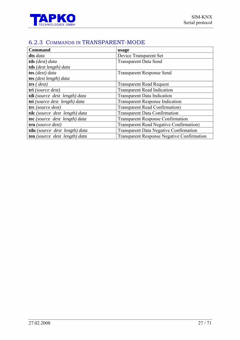
6.2.3 COMMANDS IN TRANSPARENT-MODE Command usage dts data Device Transparent Set tds (dest) data tds (dest length) data
Transparent Data Send
tes (dest) data tes (dest length) data
Transparent Response Send
trs ( dest) Transparent Read Request tri (source dest) Transparent Read Indication tdi (source dest length) data Transparent Data Indication tei (source dest length) data Transparent Response Indication trc (source dest) Transparent Read Confirmation) tdc (source dest length) data Transparent Data Confirmation tec (source dest length) data Transparent Response Confirmation trn (source dest) Transparent Read Negative Confirmation) tdn (source dest length) data Transparent Data Negative Confirmation ten (source dest length) data Transparent Response Negative Confirmation

SIM-KNX Serial protocol
28 / 71 27.02.2008
6.3 COMMAND REFERENCE (GENERAL)
6.3.1 ACCESSING INTERFACE OBJECTS
SET INTERFACE OBJECT DATA ids (ioIndex propertyID) data ids (ioIndex propertyID elementIndex) data
sets the data of one property of an interface object. The property is selected via interface object index and propertyID. If the property is implemented as an array, the elements are selected via elementIndex Parameter ioIndex index to the interface object
allowed: single values propertyID ID of the property
allowed: single values elementIndex element of the property
allowed: single values is set to 1, if skipped
data Data, which are written to the property. allowed: single values, hex stream
Example ids (5 52) 1
GET INTERFACE OBJECT DATA idg (ioIndex propertyID) idg (ioIndex propertyID elementIndex)
returns the data of one property of an interface object. The property is selected via interface object index and propertyID. If the property is implemented as an array, the elements are selected via elementIndex Parameter ioIndex index to the interface object
allowed: single values propertyID ID of the property
allowed: single values elementIndex element of the property
allowed: single values is set to 1, if skipped
Return values data Data, which are read from the property. Example idg (5 52)
<idg (5 52)>$01

SIM-KNXSerial protocol
27.02.2008 29 / 71
6.3.2 DEVICE SETTINGS
GET PHYSICAL ADDRESS dag
returns the physical address of the SIM-KNX. Parameter - Return value physicalAddress physical address as one single value Example dag
<dag>$ffff
SET PHYSICAL ADDRESS das physicalAddress
This command is modifying the internal flash memory. This command should only be used at configuration time and not on a permanent basis. Parameter physicalAddress physical address
allowed: single values Return value Example das $1508
<das $1508 >
SIM-KNX Serial protocol
30 / 71 27.02.2008
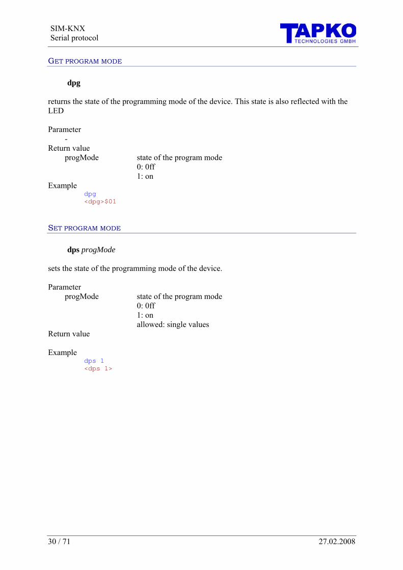
GET PROGRAM MODE dpg
returns the state of the programming mode of the device. This state is also reflected with the LED Parameter - Return value progMode state of the program mode
0: 0ff 1: on
Example dpg
<dpg>$01
SET PROGRAM MODE dps progMode
sets the state of the programming mode of the device. Parameter progMode state of the program mode
0: 0ff 1: on allowed: single values
Return value Example dps 1
<dps 1>

SIM-KNXSerial protocol
27.02.2008 31 / 71
RESTART dr
executes a restart of the SIM-KNX, after a delay of 50ms Parameter - Return value - Example dr
<dr> gui $011
GET STATE OF DEVICE dsg
returns various states of the device Parameter - Return value bit0 0: normal mode
1: transparent mode bit1 1: application loaded bit2 1: application is running bit7 1: device is in program mode Example dsg
<dsg>$06
1 if the global indication for restart is set

SIM-KNX Serial protocol
32 / 71 27.02.2008
GET VERSION dvg
returns the version of the SIM-KNX. Parameter - Return value device version single value, which shows the kind and version of this device.
high byte: general type of the device: 00: means bus coupling via TP1 media low byte: version of this device
protocol version version of the software protocol high byte: main version of this protocol. If this version changes the protocol may have incompatible changes low byte: sub version of this protocol. Higher sub versions are always upward compatible.
active Objects number of activated communication objects Example dvg
<dvg>$0001 $0001 $80
RESET TO MANUFACTURER STATE gci
Clears all settings which were done via ETS or over the serial interface and executes a restart. Example gci

SIM-KNXSerial protocol
27.02.2008 33 / 71
6.3.3 PARAMETER
PARAMETER DATA GET pdg (index) pdg (index count)
gets the Parameter, which could be written only with ETS. Parameter index index to the Parameter count number of Parameter, which should be read
is set to 1 if skipped Return values data Example pdg (10 4)
<pdg (10 4)>$01 $02 $03 $04 pdg (11) <pdg (11)>$02

SIM-KNX Serial protocol
34 / 71 27.02.2008
6.4 COMMAND REFERENCE (RAW / INTEROPERABILITY MODE)
6.4.1 CONFIGURATION
SET EVENT GENERATION dus globalEvent
sets the configuration of the global event generation This command is modifying the internal flash memory. This command should only be used at configuration time and not on a permanent basis. Parameter globalEvent send global Event:
bit 0: at restart bit 3: if global update flag is set bit 4: if global changed flag is set bit 6: if time out on serial interface has occured bit 7: if global receive timeout is set
Return value - Example dus $01
<dus $01> For getting the status see 7.1 property ID 128.

SIM-KNXSerial protocol
27.02.2008 35 / 71
6.4.2 ACCESSING GROUP COMMUNICATION OBJECTS (RAW MODE)
SET OBJECT DATA ods (objectNr) data
sets the data of a group communication object inside the SIM-KNX. The transmission is automatically initiated depending on the send condition. This command deletes the appropriate update-flag. Depending on the object length the data of this command can be from 1 byte up to 14 bytes. Parameter ObjectNr Number of the group communication object which are manipulated
allowed: single values Data Data, which are written to the group communication object.
allowed: single values, hex stream Take care that you set the correct length of the data.
Example ods (0) 1
<ods (0) 1> ods ($1) $0 $1 $2 <ods ($1) $0 $1 $2> ods (1) #000102 <ods (1) #000102>
GET OBJECT DATA odg (objectNr)
returns the data of a group communication object inside the SIM-KNX. This command delete the appropriate update-flag. Depending on the object length the data returned can be from 1 byte up to 14 bytes. Parameter objectNr Number of the group communication object which is manipulated
allowed: single values Return values data Data, which are read from the group communication object. Example odg (0)
<odg (0)> $01

SIM-KNX Serial protocol
36 / 71 27.02.2008
6.4.3 ACCESSING GROUP COMMUNICATION OBJECTS (INTEROPERABILITY MODE)
SET OBJECT VALUE ovs (objectNr) data
sets the value of a group communication object inside the SIM-KNX. The transmission is automatically initiated depending on the send condition. The data and its format are depending on the configured data point type. Parameter objectNr Number of the group communication object which is manipulated
allowed: single values data Data, which are written to the group communication object.
allowed: single values, hex stream depending on data point type Example ovs (0) 1
<ovs (0) 1> ovs ($1) 2100 <ovs ($1) 2100>
GET OBJECT VALUE ovg (objectNr)
Returns the value of a group communication object inside the SIM-KNX. The data and its format are depending on the configured data point type. Parameter objectNr Number of the group communication object which is manipulated
allowed: single values Return values data Data, which are read from the group communication object.
the data format is depending on data point type Example ovg (0)
<ovg (0)>1 ovg ($1) <ovg ($1)>2100>

SIM-KNXSerial protocol
27.02.2008 37 / 71
6.4.4 ACCESSING GROUP COMMUNICATION OBJECTS (RAW / INTEROPERABILITY MODE)
SEND GROUP TELEGRAM odt (objectNr)
Starts the transmission of the value of a group communication object on the KNX as A_ValueWrite, without a check of the send condition. Parameter objectNr Number of the group communication object which is manipulated
allowed: single values Example odt (0)
<odt (0)>
SEND GROUP READ TELEGRAM odr (objectNr)
Starts the request of the value of a group communication object. An A_ValueRead is transmitted on KNX. Parameter objectNr Number of the group communication object which is manipulated
allowed: single values Example odr (1)
<odr (1)>
GET RAM-FLAGS ofg (objectNr)
Returns the RAM-flags of the object Parameter objectNr Number of the group communication object which is manipulated
allowed: single value Return values RAM-Flags RAM-flags of the Object Example ofg (1)
<ofg (1)> $01

SIM-KNX Serial protocol
38 / 71 27.02.2008
STRUCTURE OF THE RAM-FLAGS The RAM-flags contain the information about the communication status of the communication object. Of your application’s interest are normally only the indications (update, value changes and rcv-timeout).
Bit 7 6 5 4 3 2 1 0 rcv-
timeout Value
ChangedUpdate read-
RequesttransmittionState
transmittionState
0 I 0 0 C U R T T
Figure 5: Structure of RAM-flags
TT transmission flags
information about the transmission of the value on KNX. R read flag
Flag to trigger the sending of value read request. This flag is used in combination with the transmission state
U update flag This flag indicates, that a value was received from the bus.
C value changed on update This flag indicates, that the value, which was received from the bus was changing the communication object value
I receive-timeout This flag was set, when no value was received inside the configured time.
0 not used

SIM-KNXSerial protocol
27.02.2008 39 / 71
RETURN THE UPDATE FLAG OF ALL GROUP OBJECT gug
Sends the update flags of all object Return values updateFlags packed update flags Example gug
<gug>$01 $00 $00 $00 $00 $00 $00 $00 $00 $00 $00 $00 $00 $00 $00 $00
RETURN THE VALUECHANGED FLAG OF ALL GROUP OBJECT gcg
Sends the valueChanged flags of all object Return values valueChangedFlags packed valueChanged flags Example gcg
<gcg>$04 $00 $00 $00 $00 $00 $00 $00 $00 $00 $00 $00 $00 $00 $00 $00
RETURN THE TIMEOUT FLAG OF ALL GROUP OBJECT gtg
Sends the update flags of all object Return values timeoutFlags packed timeout flags Example gtg
<gtg>$10 $00 $00 $00 $00 $00 $00 $00 $00 $00 $00 $00 $00 $00 $00 $00

SIM-KNX Serial protocol
40 / 71 27.02.2008
6.4.5 CONFIGURE GROUP COMMUNICATION OBJECTS All this commands are modifying the internal flash memory. This commands should only be used at configuration time and not on a permanent basis.
CONFIGURE GROUP ADDRESSES
SET SENDING GROUP ADDRESS ogs (objectNr) group
sets the sending group address of a group communication object. The existing sending group address is still connected as receiving group address. Parameter objectNr Number of the group communication object which is manipulated
allowed: single values Group sending group address as one single value
allowed: single values or ETS format Example ogs (0) $affe
<ogs (0) $affe> ogs (0) 21/2046 <ogs (0) 21/2046> ogs (0) 21/7/254 <ogs (0) 21/7/254> ogs (0) 21/7/$fe <ogs (0) 21/7/$fe>
ADD GROUP ADDRESS oga (objectNr) group
adds a group address to a group communication object as receiving group address. If no group address is existing before, this group address also becomes the sending group address. Parameter objectNr Number of the group communication object which is manipulated
allowed: single values group group address as one single value
allowed: single values or ETS format Example oga (0) $affe
<oga (0) $affe> oga (0) 21/2046 <oga (0) 21/2046> oga (0) 21/7/254 <oga (0) 21/7/254> oga (0) 21/7/$fe <oga (0) 21/7/$fe>

SIM-KNXSerial protocol
27.02.2008 41 / 71
DELETE GROUP ADDRESS ogd (objectNr) group
deletes one or all group addresses of a group communication object. If the sending group address is deleted, the next one becomes the sending group address Parameter objectNr Number of the group communication object which is manipulated
allowed: single values group group address as one single value
allowed: single values and string “all” Example ogd (0) $4711
<ogd (0) $4711> ogd (0) 8/1809 <ogd (0) 8/1809> ogd (0) 8/7/17 <ogd (0) 8/7/17> ogd (1) “all” <ogd (1) “all”>
GET GROUP ADDRESSES ogg (objectNr)
returns the group addresses of a group communication object. The first group address is the sending one Parameter objectNr Number of the group communication object which is manipulated
allowed: single values Return values group group addresses as single values in hex-format Example ogg (0)
<ogg (0)>$4711 $affe

SIM-KNX Serial protocol
42 / 71 27.02.2008
CONFIGURE GROUP COMMUNICATION OBJECTS
SET OBJECT CONFIGURATION ocs (objectNr) DPT objectType comFlags sendConfig rcvConfig time
Sets the configuration of the group communication object To configure the communication object in Interoperability mode, set the DPT and leave the object type to 0. To configure the communication object in Raw mode, set the DPT to 0, and configure the length via the parameter object type. When the wildcard ‘*’ is used in this command, the related parameter was not changed. Parameter objectNr Number of the group communication object which is manipulated
allowed: single values, * DPT data point type
allowed: single values, * see also
Page 44 Data point types (DPT) objectType object type
allowed: single values, * see also
Page 48 Group object types (objectType) comFlags configuration flags of the group communication object
allowed: single values, * see also
Page 51 Structure of the configuration flags (comFlags) sendConfig configuration when the value is sent
allowed: single values, * see also
Page 49 Send configuration (sendConfig) rcvConfig configuration when indications will be sent
allowed: single values, * see also
Page 50 Receive configuration (rcvConfig) time delay time, when the time is set to 0 the send and receive timeout
was disabled. allowed: single values, *
Return values Example ocs (0) 1 0 $df $0001 $0001 0
<ocs (0) 1 0 $df $0001 $0001 0> ocs ($1) 9 0 &df $0002 $0004 120 <ocs ($1) 9 0 &df $0002 $0004 120>

SIM-KNXSerial protocol
27.02.2008 43 / 71
GET OBJECT CONFIGURATION ocg (objectNr)
Returns the configuration of the group communication object Parameter objectNr Number of the group communication object which is manipulated
allowed: single values Return values DPT data point type
see also Page 44 Data point types (DPT)
objectType object type see also
Page 48 Group object types (objectType) comFlags configuration flags of the group communication object
see also Page 51 Structure of the configuration flags (comFlags)
sendConfig configuration when the value is sent see also
Page 49 Send configuration (sendConfig) rcvConfig configuration when indications will be sent
see also Page 50 Receive configuration (rcvConfig)
time delay time Example ocg(0)
<ocg(0)> 1 0 $df $0001 $0001 0

SIM-KNX Serial protocol
44 / 71 27.02.2008
DATA POINT TYPES (DPT) The following DPT are supported by SIM-KNX: For information about the usage, please check also the KNX documentation, especially the Specification of the interworking datapoint types. Value (code) Data point type expected Values / response Format
1 DPT 1 “Boolean” Format: V V {0,1}: value (0=off, 1=on) Object Size: 1 Bit Usage: on / off blinds up / down enable / disable
2 DPT 2 “1-Bit controlled”
Format: C V C {0,1}: control (0=off, 1=on) V {0,1}: value (0=off, 1=on) Object Size: 2 Bit Usage: Priority
3 DPT 3 “3-Bit controlled”
Format: C V C {0,1}: control (0=off, 1=on) V {0 .. 7}: value Object Size: 4 Bit Usage: Dimming Control Blinds Control Boiler Mode
4 DPT 4 “character set” Format: String with one charater Object Size: 1 Byte
5 DPT 5 “8-Bit unsigned value” (DPT5.001 DPT_Scaling)
Format: Value {0..100} allowed: single value Object Size: 1 Byte Usage: Scaling (0..100%) complex advanced sendingtransmit conditions: send on difference send on threshold Usage: Scaling (0..100%) Absolute dimming
200 DPT 5 “8-Bit unsigned value” (DPT5.003 DPT_Angle)
Format: Value {0..360} allowed: single value Object Size: 1 Byte advanced transmit conditions: send on difference send on threshold Usage: Angle(0..360°) complex sending: send on difference send on threshold
SIM-KNXSerial protocol
27.02.2008 45 / 71
Value (code) Data point type expected Values / response Format
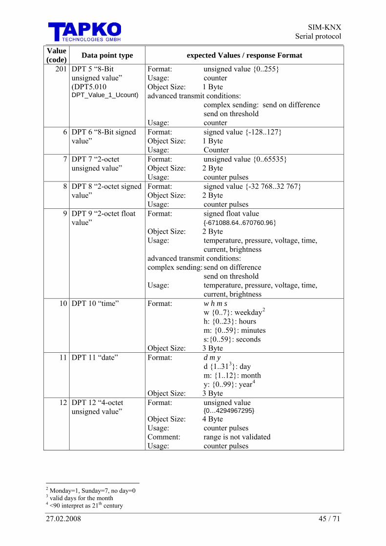
201 DPT 5 “8-Bit unsigned value” (DPT5.010 DPT_Value_1_Ucount)
Format: unsigned value {0..255} Usage: counter Object Size: 1 Byte advanced transmit conditions: complex sending: send on difference send on threshold Usage: counter
6 DPT 6 “8-Bit signed value”
Format: signed value {-128..127} Object Size: 1 Byte Usage: Counter
7 DPT 7 “2-octet unsigned value”
Format: unsigned value {0..65535} Object Size: 2 Byte Usage: counter pulses
8 DPT 8 “2-octet signed value”
Format: signed value {-32 768..32 767} Object Size: 2 Byte Usage: counter pulses
9 DPT 9 “2-octet float value”
Format: signed float value {-671088.64..670760.96} Object Size: 2 Byte Usage: temperature, pressure, voltage, time, current, brightness advanced transmit conditions: complex sending: send on difference send on threshold Usage: temperature, pressure, voltage, time, current, brightness
10 DPT 10 “time” Format: w h m s w {0..7}: weekday2 h: {0..23}: hours m: {0..59}: minutes s:{0..59}: seconds Object Size: 3 Byte
11 DPT 11 “date” Format: d m y d {1..313}: day m: {1..12}: month y: {0..99}: year4 Object Size: 3 Byte
12 DPT 12 “4-octet unsigned value”
Format: unsigned value {0…4294967295} Object Size: 4 Byte Usage: counter pulses Comment: range is not validated Usage: counter pulses
2 Monday=1, Sunday=7, no day=0 3 valid days for the month 4 <90 interpret as 21th century

SIM-KNX Serial protocol
46 / 71 27.02.2008
Value (code) Data point type expected Values / response Format
13 DPT 13 “4-octet signed value”
Format: signed value { -2147483648 .. + 2147483647} Object Size: 4 Byte Usage: counter value Comment: range is not validated Usage: counter value
14 DPT 14 “4-octet float value”
Format: float value Object Size: 4 Byte
15 DPT 15 “Access” Format: 4 byte allowed: single values Object Size: 4 Byte
16 DPT 16 “String” Format: string {maximum length: 14 characters}5 valid for object number >112Object Size:
14 Byte 17 DPT 17 “scene” Format: unsigned value {0..63}
Object Size: 6 Bit 18 DPT 18 “Scene
control” Format: 2 values C V C {0,1}: 0= control, 1=learn V {0..63}: value Object Size: 1 Byte
19 DPT 19 “date time” Format: 9 values d m y w h m s f1 f2 d {1..316}: day m: {1..12}: month y: {0..199}: year w {0..7}: weekday7 h: {0..24}: hours m: {0..59}: minutes s:{0..59}: seconds f1,f2
(see also: page 70 Further Documentation) Object Size: 8 f1,f2 (see also: page 70 Further Documentation) valid for object number >112
20 DPT 20 Format: unsigned value {0..255} Object Size: 1 Byte
21 DPT 21 “general status”
Format: unsigned value {0..255} Object Size: 1 Byte
22 DPT 22 “16-Bit Set“ Format: 2 unsigned value {0..255} Object Size: 2 Byte
23 DPT23 “Enum8” Format: 2bit {0..3} Object Size: 2 Byte
5 Response has always 14 characters (unused characters were set to 0 <NULL>) 6 valid days for the month 7 Monday=1, Sunday=7, no day=0

SIM-KNXSerial protocol
27.02.2008 47 / 71
EXAMPLES
DIMMING CONTROL Command Value binary (Control Value) Action ovs(9) $1 1 1 001 1/1 brighter (dim to on) ovs(9) 0 $1 0 001 1/1 darker (dim to off) ovs(9) 1 8 1 100 ⅛ brighter ovs(9) 0 $3 0 011 ¼ darker ovs(9) 1 $0 1 000 Stop dimming
121
−= stepcodeValue
TEMPERATURE8 Command ovs(9) –12.75 ovs(9) 37
ABSOLUTE DIMMING Command Usage Action ovs(9) $13 Wind direction 26.82° ovs(9) $A5 Relative Brightness 64.71% ovs(9) $DC Counter 220
TIME Command Action ovs(9) 1 12 45 59 Monday, 12:45:59 ovs(9) 5 $A $1F $2F Friday, 10:31:47
DATE Command Action ovs(9) 24 12 56 24.12.2056 ovs(9) $F $B 5C 15.11.1992
8 Due to conversion of the value, it may happen that the value you read back from SIM-KNX is not exactly the one you write

SIM-KNX Serial protocol
48 / 71 27.02.2008
GROUP OBJECT TYPES (OBJECTTYPE) The group object types are according to the resource definition in the Konnex KNX Handbook.
value (code) size used memory 0, 1 bit 1 byte 1, 2 bit 1 byte 2, 3 bit 1 byte 3, 4 bit 1 byte 4, 5 bit 1 byte 5, 6 bit 1 byte 6, 7 bit 1 byte 7, 1 byte 1 byte 8, 2 byte 2 byte 9, 3 byte 3 byte 10, 4 byte 4 byte 11, 6 byte 6 byte 12, 8 byte 8 byte 13, 10 byte 10 byte 14 14 byte 14 byte

SIM-KNXSerial protocol
27.02.2008 49 / 71
SEND CONFIGURATION (SENDCONFIG) This byte contains configuration of the send conditions: Bit Meaning 0 send on receive
1: sends the object value when the value was received from the serial interface 1 send on change (not DPT1)
1: sends the object value when the value received from the serial interface different than the current value
1 send on falling edge (DPT1 only) 1: sends the object value when the value changes from 1 to 0
2 send on rising edge (DPT1 only) 1: sends the object value when the value changes from 0 to 1
3 reserved (0) 4 reserved (0) 5 reserved (0) 6 selection of the timer usage
0: send-timer 1: receive-timer
7 selection of the time base (timer is activated when time != 0) 0: time in seconds 1: time in minutes
8 reserved (0) 9 reserved (0) 10 reserved (0) 11 reserved (0) 12 reserved (0) 13 reserved (0) 14 reserved (0) 15 reserved (0)

SIM-KNX Serial protocol
50 / 71 27.02.2008
RECEIVE CONFIGURATION (RCVCONFIG) This byte contains configuration of the receive conditions: Bit Meaning 0 usage of the indication
0: single indication 1: global indication
1 format of the single-indication 1: send Object-Value with the indication
2 reserved (0) 3 reserved (0) 4 reserved (0) 5 reserved (0) 6 reserved (0) 7 reserved (0) 8 reserved (0) 9 reserved (0) 10 reserved (0) 11 indication on rcv 12 indication on changed 13 reserved (0) 14 reserved (0) 15 indication on timeout

SIM-KNXSerial protocol
27.02.2008 51 / 71
STRUCTURE OF THE CONFIGURATION FLAGS (COMFLAGS) The configuration-flags contains the information about the communication. They are identical to the flags in ETS in the „Edit Object“ dialog.
Bit 7 6 5 4 3 2 1 0 read
response enable
transmit enable
0 write enable
read enable
comm. enable
priority priority
0 U T 0 W R C P P
PP priority possible values are:
3 = low 1 = high 2 = urgent 0 = system (do not use!) C Communication Enable
Enables the communication of the object R Read Enable
Has to be set, if the Object-value should be readable from the EIBKNX W Write Enable
Enables the receiving from the EIBKNX T Transmit Enable
Enables the sending to the EIBKNX U Update Enable
Has to be set, if the Object-value should be updated with read-responses
0 not used Definition of the direction: devicewrite
transmit
read response
Figure 6: direction of telegrams
The default configuration is “0xD3”.
read response enable
transmit enable
write enable
read enable comm. enable
priority priority
Yes Yes Yes No No Yes yes
SIM-KNX Serial protocol
52 / 71 27.02.2008
6.4.6 INDICATIONS The following commands are sent from the Module without any requests. They are independent from the Response-Syntax.
SENDS THE GLOBAL UPDATE FLAG gui
Sends the global update flag Return values global updateFlag bit 0: restart of the device
bit 3: update flag bit 4: changed flag bit 6: time out on serial interface has occured bit 7: receive timeout
Example gui $01
SENDS THE UPDATE FLAG FOR A COMMUNICATION OBJECT oui
sends the global update flag the update-, transmit- and timeout-flag are cleared after the indication Return values groupObjectNo Number of the group communication object, which was updated flags RAM-flags of the communication object (Object Value) the actual Value of the communication object
sending of this value is dependent of the rcvConfig Example oui $01 $10
oui $01 $10 50

SIM-KNXSerial protocol
27.02.2008 53 / 71
6.5 COMMAND REFERENCE (TRANSPARENT MODE)
DEVICE TRANSPARENT SET dts data
switch on/off transparent mode Parameter Data BIT0: 1 = transparent mode enabled
0 = transparent mode disabled BIT1: 1 = send ack on every group-message (recommended) 0 = no ack on every group-message BIT2: 1 = generate confirmation on serial interface 0 = no confirmation on serial interface BIT3: not used BIT4: format of address 0 = Hex – format 1 = format depends on bit 5 BIT5: 1 = address as 2-level group address 0 = address as 3-level group address
Example dts 7
TRANSPARENT DATA SEND tds (dest) data tds (dest length) data
Sends ValueWrite Parameter dest also usable as ETS-Group length 0 = 1..6Bit (default)
1 = 1Byte …
data Data, which are send to destination allowed: single values
Example tds(2/0/0) 2

SIM-KNX Serial protocol
54 / 71 27.02.2008
TRANSPARENT RESPONSE SEND tes (dest) data tes (dest length) data
Sends ValueResponse Parameter dest also usable as ETS-Group length 0 = 1..6Bit (default)
1 = 1Byte …
data Data, which are send to destination allowed: single values
Example tes ($1000) $01
tes (2/0/1 2) $01 $02
TRANSPARENT READ SEND trs (dest)
Sends ValueRead Parameter dest also usable as ETS-Group Example trs ($1000)
TRANSPARENT READ INDICATION tri (source dest)
Gets a value read indication Parameter Source physical address Dest group address Example tri ($ffff $1000)

SIM-KNXSerial protocol
27.02.2008 55 / 71
TRANSPARENT DATA INDICATION tdi (source dest length) data
Gets a value write indication Parameter source physical address dest group address length 0 = 1..6Bit
1 = 1Byte …
data Data, which are received for destination Example tdi ($ffff $17d0 $06) $01 $00 $00 $00 $00 $01
TRANSPARENT RESPONSE INDICATION tei (source dest length) data
Gets a value response indication Parameter Source physical address Dest group address Length 0 = 1..6Bit
1 = 1Byte …
Data Data, which are received for destination Example tei ($ffff $17d0 $00) $01
TRANSPARENT READ CONFIRMATION trc (source dest)
Gets a value read confirmation – only if enabled in dts (bit2) Parameter Source physical address Dest group address Example trc ($ffff $1000)

SIM-KNX Serial protocol
56 / 71 27.02.2008
TRANSPARENT DATA CONFIRMATION tdc (source dest length) data
Gets a value write confirmation – only if enabled in dts (bit2) Parameter source physical address dest group address length 0 = 1..6Bit
1 = 1Byte …
data Data, which are received from destination Example tdc ($1508 $0002 $00) $01
TRANSPARENT RESPONSE CONFIRMATION tec (source dest length) data
Gets a value response confirmation – only if enabled in dts (bit2) Parameter source physical address dest group address length 0 = 1..6Bit (default)
1 = 1Byte …
data Data, which are received from destination Example tec ($1508 $0002 $00) $01
TRANSPARENT READ NEGATIVE CONFIRMATION trn (source dest)
Gets a value read negative confirmation – only if enabled in dts (bit2) Parameter source physical address dest group address Example trn ($1508 $1000)

SIM-KNXSerial protocol
27.02.2008 57 / 71
TRANSPARENT DATA NEGATIVE CONFIRMATION tdn (source dest length) data
Gets a value write negative confirmation – only if enabled in dts (bit2) Parameter source physical address dest group address length 0 = 1..6Bit
1 = 1Byte …
data Data, which are received from destination Example tdn ($1508 $1000 $00) $01
TRANSPARENT RESPONSE NEGATIVE CONFIRMATION ten (source dest length) data
Gets a value response negative confirmation – only if enabled in dts (bit2) Parameter source physical address dest group address length 0 = 1..6Bit
1 = 1Byte …
data Data, which are received from destination Example ten ($1508 $1000 $00) $01
SIM-KNX Serial protocol
58 / 71 27.02.2008
6.6 ERROR CODES errCode internal Name meaning possible reasons $0010 TRANSMIT_FAIL requested Transmission
of an object failed - object is already transmitting
$0101 APPL_STOP requested command is
denied, because Application is stopped
- illegal memory-Access over the Bus - incomplete download with ETS
$0102 NO_OBJ requested Object-Number is invalid
$0103 NUMBER_EXP expected value should have a number format
$0104 VALUE_RANGE the value is out of range $0105 COMMAND_END end of the command
expected
$0106 TYPE_RANGE given type of the object is not allowed
- requested object type exceeds the size of the object
$0109 TO_MUCH_VALUES bytestream is too long $010b NUMBER_OR_COMMA a number or a comma is
expected
$010d NUMBER_OF_INDEX too much indices are given
$010e LINK_WRITE manipulation of group-addresses failed
- deleting of non existing address - maximum number of addresses reached
$010f NO_OF_VALUES number of values in bytestream is incorrect
$0110 SYNTAX_ERROR invalid syntax $0111 STRING_EXP expected parameter is a
string
$0112 SOE_KEY_ALREADY_EXIST security key already set $0112 STRING_SIZE the size of the string is
too large
$0210 TYPE_EXPECTED command expected - serial string doesn’t
start with an command
$0215 ILLEGAL_OPERATION unknown command $0216 NO_PROP Property in
Interfaceobject not found
$0217 IO_ELEMENT elementindex for the property to large
$0218 RO property is ReadOnly $0219 TYPE_MISMATCH Objecttype and DPT are
incompatible
$0220 DPT_NOT_FOUND given DPT is not supported

SIM-KNXSerial protocol
27.02.2008 59 / 71
errCode internal Name meaning possible reasons $0221 WRONG_PARAMETER given parameter is invalid $0222 ACCESS_DENIED access to the given
command is denied some commands are disabled after an ETS-download
$0223 NO_PARAMETER the requested userParameter doesn’t exist
$0224 TO_MUCH_PARAMETER to much userParameter are requested

SIM-KNX Implemented Application Interface Objects
60 / 71 27.02.2008
7 IMPLEMENTED APPLICATION INTERFACE OBJECTS Access to the interface objects of this device is possible from the bus with stander property access mechanisms and through the serial interface with the commands ids (ioIndex propertyID elementIndex) dat ) and idg (ioIndex propertyID elementIndex). For access from the bus tools like “Device editor” provided with ETS3 could be used.
7.1 OBJECT INDEX: 5 In the commands ids and idg for this object the ioIndex is always 5. Property ID
Type Read/Write
Element Index
Usage
1 PDT_UNSIGNED_INT R
Object Type
Parameter of the serial interface 50 PDT_GENERIC_02 RW 1 For detailed description of the 2 bytes configuring the serial
interface see 6.1.1 Example: setting default values to the serial interface ids (5 50) $31 $00
51 PDT_GENERIC_02 RW
Parameter for transparent mode See 9.3 Example: reading the transparent mode setting idg (5 51)
52 PDT_GENERIC_01 RW
Syntaxe options See 6.1.3 Example: enable responding OK if no data in response ids (5 52) $02
53 PDT_GENERIC_02 R
Reserved
54 PDT_GENERIC_01 RW
Controls the replacement of text on receiving from the serial interface 0 = disable text replacement 1 = enable text replacement The original strings and replacement strings are defined in property 136 Example: enable replacement of text ids (5 54) $01
55 PDT_GENERIC_01 RW
Controls the sending of user-defined strings on the serial interface ( replacing the standard indication) on reception of group oriented communication objects 0 = disable 1 = enable

SIM-KNXImplemented Application Interface Objects
27.02.2008 61 / 71
60 Array
PDT_GENERIC_06 RW
Object configuration Every element (index) configures one communication object The element structure is as follows: Byte 0: Data point types (DPT) Byte 1: delay time Byte 2: upper byte Send configuration (sendConfig) Byte 3: lower byte of Send configuration (sendConfig) Byte 4: upper byte of Receive configuration (rcvConfig) Byte 5: lower byte of Receive configuration (rcvConfig)
1 Configuration for communication object 0 … … 128
(254) Configuration for communication object 127 (253)
96 Array PDT_GENERIC_06 RW
User definable serial number Example: getting the serial number idg (5 96) Example: setting the 6 byte serial number 123456789ABC ids (5 96) $12$34 $56 $78 $9A $BC
128 PDT_GENERIC_01 RW
Global event generation See 6.4.1 Example: reading the global event generation setting idg (5 128)
130 PDT_GENERIC_01 RW
Reserved
132 Array PDT_GENERIC_06 RW
Reserved
133 Array PDT_GENERIC_01 RW
Reserved
134 Array PDT_GENERIC_01 RW
User defined parameter (ETS or local) in non volatile memory See also command pdg 6.3.3 Example: reading byte 4 of parameter idg (5 134 4) Example: writing byte 4 with $D6 ids (5 134 4) $D6
135 Array PDT_GENERIC_01 RW
Complex send conditions
Strings to be replaced and replacement strings. Replacement of complete strings or string fragments received from serial interface before the command string is processed for execution. If the string is shorter then 32 bytes it is ‘0’ terminated. For explanation of function see: “Using SIM-KNX with Doepke fingerprintsensor” in “SIM-KNX EVALUATION KIT Documentation”.
1 .. 32 1.st original string that should be replaced 33 .. 64 1.st replacement string inserted instead the original 65 .. 96 2.nd original string that should be replaced 97 .. 128 2.nd replacement string inserted instead the original
… … … …
1985 .. 2016 32.nd original string that should be replaced
136 Array PDT_GENERIC_01 RW
2017 .. 2048 32.nd replacement string inserted instead the original

SIM-KNX Implemented Application Interface Objects
62 / 71 27.02.2008
Replacement indication text on reception.
Each replacement is a structure with 35 bytes: Byte 0 – 32: string that is sended Byte 33 object number where to replace indication Byte 34 value = 0 send this string regardless of received value value ≠ 0 send string if received value matches value in byte 35 byte 35 compare value
1 .. 35 Replacement structure 1 36 .. 67 Replacement structure 2
… …
137 Array PDT_GENERIC_01 RW
1086 .. 1120 Replacement structure 32 1409 PDT_GENERIC_01
RW Controls the communication time out supervision of the serial
interface - time value = 0 disable time out supervision value ≠ 0 enable time out supervision value is the time out value ids (5 140) $10 When enabled, a time out is detected when the given time expires and no communication on the serial interface takes place. The time out flag is set an the given object with the given value is sent to the bus. After communication resumes, depending on configuration, this changed situations is sent on the bus or not. A global update indication informing about the previous lost communication is sended on the serial interface.
1419 PDT_GENERIC_02 RW
Configuration 1 of the communication time out supervision of the serial interface – behaviour 1.st byte: not used 2.nd byte: Bit 7 0 = time (value in byte 1) in seconds 1 = time (value in byte 1) in minutes Bit 6, 5, 4, 3, 2, 1 not used Bit 0 0 = do nothing on communication resume 1 = clear time out flag on communication resume and time out restart On communication resume time out supervision starts automatically if enabled (property 140). On value change of the time out flag the object (number in property 142) with value given in property 143 is sended
1429 PDT_GENERIC_02 RW
Configuration 2 of the communication time out supervision of the serial interface – object number 1.st byte: not used 2.nd byte: Number of communication object that is used for sending communication lost alarm message
1439 PDT_GENERIC_02 RW
Configuration 3 of the communication time out supervision of the serial interface – object value 1.st byte: this value is used when time out flag is set 2.nd byte: this value is used when time out flag is cleared
9 available since protocol version $0106

SIM-KNXETS
27.02.2008 63 / 71
8 ETS 8.1 GROUP OBJECTS Number of group addresses 254 Number of associations 254 Number of communication objects 128 Address of association table 0x41FF Address of communication object table 0x43FC
8.2 PARAMETER Address Internal Name Description 0x47FA serParam 0x47FC syntaxOptions. 0x47FE globalEventGeneration. 0x47FF eventSyntax. 0x4800 securityLevel. 0x4801 enableReplacement. 0x4802 sendString.
0x4846 + 6*x + 0 objectConfig[x].objEisTypes
Configuration for Object x Datapoint type (DPT) x is in the range of 0..127
0x4846 + 6*x + 1 objectConfig[x].repTime
Configuration for Object x Datapoint type (DPT) x is in the range of 0..127
0x4846 + 6*x + 2 objectConfig[x].sendConfig
Configuration for Object x Datapoint type (DPT) x is in the range of 0..127
0x4846 + 6*x + 4 objectConfig[x].rcvConfig
Configuration for Object x Datapoint type (DPT) x is in the range of 0..127
0x4E3C + 32*x + 0 complexSendCondition[x].config Advanced send configuration for Object “x” x is in the range of 0..15
0x4E3C + 32*x + 2 complexSendCondition[x].diffSendValue
Advanced send configuration for Object “x” x is in the range of 0..15
0x4E3C + 32*x + 6 complexSendCondition[x].hysteresesOn
Advanced send configuration for Object “x” x is in the range of 0..15
0x4E3C + 32*x + 10complexSendCondition[x].hysteresesOff
Advanced send configuration for Object “x” x is in the range of 0..15
0x4E3C + 32*x + 14complexSendCondition[x].objectIndex
Advanced send configuration for Object “x” x is in the range of 0..15
0x4E3C + 32*x + 15 complexSendCondition[x].value0Advanced send configuration for Object “x” x is in the range of 0..15
0x4E3C + 32*x + 16 complexSendCondition[x].value1Advanced send configuration for Object “x” x is in the range of 0..15
0x503C .. 0x523B userParameter
0x523C + 64*x + 0 sendOnString[x].originalString String Replacement x is in the range of 0..32
0x523C + 64*x + 32 sendOnString[x].replaceString String Replacement x is in the range of 0..32
0x5A3C + 35*x + 0 sendStringInd[x].sendString Send String on received Object x is in the range of 0..32
0x5A3C + 35*x + 32 sendStringInd[x].objectNr Send String on received Object x is in the range of 0..32

SIM-KNX ETS
64 / 71 27.02.2008
Address Internal Name Description
0x5A3C + 35*x + 33 sendStringInd[x].evaluateValue Send String on received Object x is in the range of 0..32
0x5A3C + 35*x + 34 sendStringInd[x].value Send String on received Object x is in the range of 0..32

SIM-KNXExamples how to use SIM-KNX
27.02.2008 65 / 71
9 EXAMPLES HOW TO USE SIM-KNX
9.1 USING SIM-KNX WITHOUT ETS-DATABASE ENTRY In this case complete configuration is done via the serial interface
• Configuration of communication objects • Assignment of group address
9.2 USING SIM-KNX WITH ETS- DATABASE ENTRY In this case the configuration of SIM-KNX is done via your database entry so no configuration is required via the serial interface During development phase it may be necessary that you configure SIM-KNX via the serial interface.
9.3 USING SIM-KNX IN TRANSPARENT MODE By switching on transparent mode with e.g.: Device Transparent Set 7 all group oriented messages are passed through from the bus to the serial interface in the form of a Transparent Data Indication (normal writing coming from the bus), Transparent Read Indication (asking a sensor its value) or a Transparent Response Indication (the answer on a request from the sensor). The information passed to the serial interface is the physical address of the originating device (source) the destination group address and the data itself (with length information) From the serial interface you can send a Transparent Data Send (normal writing to the bus), Transparent Response Send (answer to a request from the bus) or Transparent Read Send (sending a request for a value to the bus). In this example no local confirmations are generated and hex format in displaying received messages is used. For getting the status of transparent mode see 7.1 property ID 51.

SIM-KNX Mechanical Specifications
66 / 71 27.02.2008
10 MECHANICAL SPECIFICATIONS 10.1 STRAIGHT CONNECTOR (-S OPTION)
m35,5mm
30,0
mm
35,5mm
36,0
mm
10,2
mm
5,3m
Figure 7: Dimensions in mm (not to scale)
5,0m
m
8x Ø
0,9mm
1,3mm 2,54mm
5,4m
m
Figure 8: Recommended Footprint
6mm
Figure 9: Necessary Isolation-Areas between KNX and Application-Circuits

SIM-KNXMechanical Specifications
27.02.2008 67 / 71
10.2 RIGHT ANGLE CONNECTOR (-RA OPTION)
35,5mm
30,0
mm
13,8
mm
3,7m
m
35,5mm
Pin1 2 3 4 5 6 7 8 Figure 10: Dimensions in mm (not to scale)
4,4m
m
8x Ø
0,9mm
1,3mm 2,54mm
Figure 11: Recommended Footprint
6mm
Figure 12: Necessary Isolation-Areas between KNX and Application-Circuits
SIM-KNX Ordering details
68 / 71 27.02.2008
11 ORDERING DETAILS SIM-KNX 128-S SIM-KNX Module with 128 communication objects and straight
connector SIM-KNX 128-R SIM-KNX Module with 128 communication objects and right
angle connector SIM-KNX 250-S SIM-KNX Module with 250 communication objects and straight
connector SIM-KNX 250-R SIM-KNX Module with 250 communication objects and right
angle connector SIM-KNX 128 USB EVA SIM-KNX Evaluation board with mounted SIM-KNX 128-R
module for USB connection SIM-KNX 128 RS232 EVA SIM-KNX Evaluation board with mounted SIM-KNX 128-R
module for RS232 connection SIM-KNX 250 USB EVA SIM-KNX Evaluation board with mounted SIM-KNX 250-R
module for USB connection SIM-KNX 250 RS232 EVA SIM-KNX Evaluation board with mounted SIM-KNX 250-R
module for RS232 connection

SIM-KNXGlossary
27.02.2008 69 / 71
12 GLOSSARY Communication Objects
see Group Communication Object Data point types (DPT)
Standardized format and usage for transmitting data via EIB / KNX. The complete list of DPTs is available at KNX Association.
KNX
Group address
Group addresses are used to link group communication objects. see Group Communication Object
Group Object
see Group Communication Object Group Communication Objects
Group communication objects contains the data points which are transmitted via runtime communication. One or more group addresses can be assigned to group communication objects. Always on group address is the sending address. Via this address the values of the group communication object are sent on the bus. The other group addresses are only used to receive values. The sending group address is set via the command ‘ogs’ or ETS. If the sending group address is deleted, the next group address becomes the sending one. Other words for group communication object are
- group object - communication objects
Individual Address
see physical address Physical Address
This address is the unique device address inside an EIB / KNX-System. This address is independent of the group addresses and is used for configuration of the device. Another word for physical address is:
- individual address

SIM-KNX Further Documentation
70 / 71 27.02.2008
13 FURTHER DOCUMENTATION KNX Handbook 3_7_2 Datapoint types10 S14 DPT_DateTime v1.0
10 http://www.konnex.org/fileadmin/downloads/03%20-%20KNX%20Standard/KNX%20Standard%20Public%20Documents/KNX%20interworking%20;%20Datapoint%20types.pdf

SIM-KNX
27.02.2008 71 / 71