
Passive Fire Protection...Passive Fire Protection Installation Drawing Catalogue. 24. 25

SIKA PASSIVE FIRE PROTECTION HANDBOOK
PROFESSIONALFIRE PROTECTION

SIKA SOLUTIONS TAME THE ELEMENTFire has been a fascinating element for thousands of years and many achievements in the history of mankind were only possible with its help. As much as controlled fire has been driving success and wealth as badly it can hurt us – when out of control – and destroy achievements of decades within minutes. Therefore it is in everybody’s interest not to lose control over this powerful and elementary force.
Sika provides comprehensive solutions where fire resistant construction is required such as commercial, public and residential buildings, steel structures and others. Fire resistant sealants, fillers and backing materials for linear seals as well as solutions for penetration seals enable safer buildings and infrastructure to be built. Our products comply with the latest relevant standards and can be used for a wide range of fire protection uses in linear seals, cavity barriers and penetration seals.

4HANDBOOK SIKA PASSIVE FIRE PROTECTION
PREFACE
The testing and classification of ‘resistance to fire’ are quite rightly, highly regulated processes that must follow very strict rules and standards. This in turn means that fire resistance test- and classification reports e.g. testing and classification in accordance with EN 13501-2 and/or EAD/ETA, can often become very long documents which are extremely difficult to read and understand – even for people familiar with passive fire protection.
In order to assist with this understanding, and as part of Sika’s customer service for the fire protection sector, we have pro-duced this helpful tool to our customers making their lives ea-sier when using our products and dealing with such voluminous testing and classifications.
In this Sika handbook the official results are “translated” into a more easily read and understood language, with all of the general rules applied and clearly stating the limitations of each application. An important part of this are easily understood illustrations of each of these applications. The illustrations only refer to one possible application – e.g. where a picture shows penetration seals for flexible walls, the same layout also applies to rigid walls. Furthermore some of the illustrations do not show all details – like insulation material in walls.
This document is designed as a useful addition, but not as a replacement to the respective third-party testing and classifica-tion reports (e.g. ETAs), which remain the only legally binding documents. If there is any confusion or seemingly contradictory information, then the official test- and/or classification reports must be followed.
VERSION 1.0 UK07/2020, based on EN 1366-3, EN 1366-4

5HANDBOOK
SIKA PASSIVE FIRE PROTECTION
CONTENTS
Preface 4
Contents 5
Introduction 7Reaction to fire, resistance to fire 7Compartmentation 9Linear seals, cavity barriers and penetration seals 10Intumescence and intumescent materials 12Linear seals, field of application 13Flexible walls, rigid walls 14EN 13501-2: classification for linear seals 15Movement joints, non-movement joints 15Linings and insulation 16Insulated and uninsulated pipes 17Pipe diameter, pipe wall thickness 18Penetration services support 19Pipe and insulation material 20Combining multiple services in one aperture 20
Selection guide and solutions to linear seals 22Product overview Linear Seals 23
Selection guide and solutions to penetration seals 34Product overview Penetration Seals 35Insulated metal pipes in walls, large apertures 36Uninsulated metal pipes in walls, large apertures 44Plastic and MLC pipes in walls, large apertures 48Cables, cable trays and conduits in walls, large apertures 54Insulated metal pipes in walls, small apertures 60Uninsulated metal pipes in walls, small apertures 64Plastic and MLC pipes in walls, small apertures 68Cables, cable trays and conduits in walls, small apertures 74Uninsulated metal pipes in floors, large apertures 76Plastic and MLC pipes in floors, large apertures 80Cables, cable trays and conduits in floors, large apertures 86Insulated metal pipes in floors, small apertures 90Plastic and MLC pipes in floors, small apertures 92

7HANDBOOK
SIKA PASSIVE FIRE PROTECTION
INTRODUCTION
This chapter is a technical introduction to the topic of passive fire protection explaining most rele-vant terms and definitions. Furthermore it shall be a helpful tool for a better understanding of rules defined in some of the relevant test- or classification standards like EN 1366-3, EN 1366-4 or EN 13501-2. Applying these rules to tested layouts will allow to cover the most possible applications on site without compromising on safety.
REACTION TO FIRE, RESISTANCE TO FIRE
Euro class Requirement Examples of materials
A1 No contribution to fire Stone, concrete, glass, most metals
A2 Insignificant contribution to fire Similar to A1 including small amounts of organic compounds
B No spread of fire and very limited contribution to fire Gypsum boards with very thin surface covering, fire rated sealants
C Very limited spread of fire Gypsum boards with thicker surface coverings
D Limited spread of fire Wood & wooden products (depending on size)
E Acceptable reaction to fire in case of a very small flame Many plastic products and materials
F Not passing requirements for classes A1-E Other materials than classes A1-E
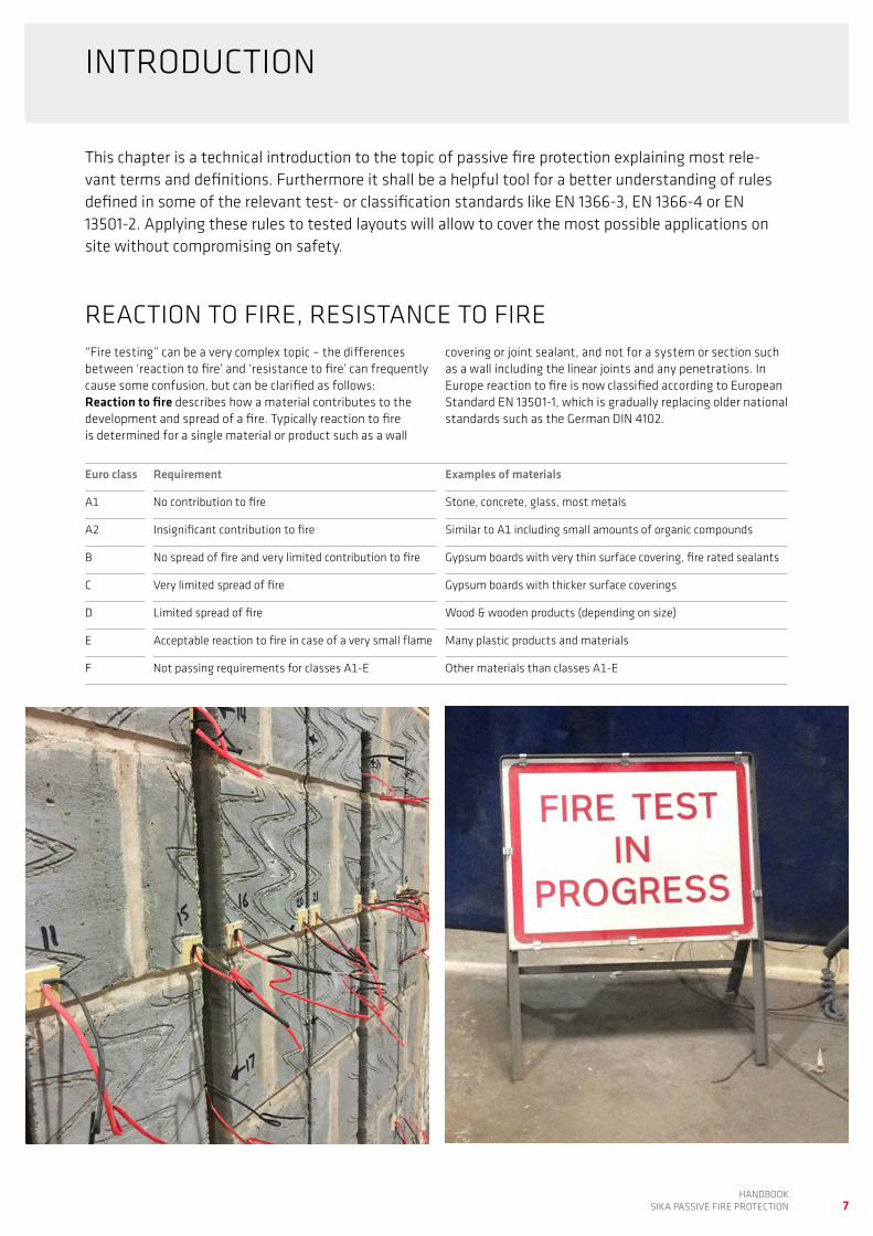
“Fire testing” can be a very complex topic – the differences between ‘reaction to fire’ and ‘resistance to fire’ can frequently cause some confusion, but can be clarified as follows:Reaction to fire describes how a material contributes to the development and spread of a fire. Typically reaction to fire is determined for a single material or product such as a wall
covering or joint sealant, and not for a system or section such as a wall including the linear joints and any penetrations. In Europe reaction to fire is now classified according to European Standard EN 13501-1, which is gradually replacing older national standards such as the German DIN 4102.

8HANDBOOK SIKA PASSIVE FIRE PROTECTION
Standard Description, scope Remark
EN 1366-3 Test standard for penetration seals Most relevant standards for resistance to fire testing. Also referred to in EAD and partly AS 1530.4
EN 1366-4 Test standard for linear joint seals
EN 13501-2 Classification standard for linear joint seals and service penetration seals
Leading to EI classes. Relevant for EN 1366 and EAD
BS 476-20 Test standard for linear joint seals and service penetration seals
British standard; superseded by EN 1366/EN 13501 but still used in some regions
EAD 350454-00-1104
Fire stopping and fire sealing products – penetration seals
Superseded ETAG 026. Leading to CE marking and DoP. Fire resistance tested acc. EN 1366
EAD 350141- 00-1106
Fire stopping and fire sealing products – linear joints and gap seals
UL Certification scheme for product safety based in the US Different test methods and requirements for different regions (e.g. UL EU and UL US/UL C)
AS 1530.4 Test and classification for linear joint seals and service penetrations
Australian standard, technically very similar to EN 1366
Certifire Certification scheme for fire protection products Relevant in the Middle East
E – IntegrityIntegrity (E) is a building element’s capability – when exposed to fire on one side – to prevent the passage of flames and hot gases to the unexposed side.
I – InsulationInsulation (I) is a building ele-ment’s capability to maintain its thermal insulation function when exposed to fire on one side. Most standards allow a maximum of 180°C tempera-ture rise on the unexposed side.
Resistance to fire describes the ability of a building element to prevent the passage of heat and flames from one side to another. Typically such building elements are walls or floors including any joints and penetrations, windows and doors etc. This means that not only a specific material or product, but an entire system or building section has to be tested.
There are many different national and international test stan-dards and classification schemes for fire resistance, however most of them follow the same principle: The building element or component for testing, including all of the service pene-trations, joints, doors, windows and the joint sealant in and around them, is fixed into a test frame which is then attached to a test furnace. The side facing towards the furnace is known as the exposed or fire side, whilst the outer side is the un-exposed or non-fire side. The furnace temperature is raised according to a defined curve reaching 945°C after 60 minutes and 1,153°C after 240 minutes. Two parameters are relevant for most fire resistance tests: Integrity and Insulation.

9HANDBOOK
SIKA PASSIVE FIRE PROTECTION
COMPARTMENTATION
Furnace with vertical linear seals after resistance to fire test acc. EN 1366-4.
Main goal of passive fire protection is not to extinguish fire but rather to prevent the spread of fire and contain it in defined compartments to minimize damage and – even more important – to allow people in other compartments to evacuate safely.
Sika products and solutions presented in this document are de-signed to maintain separation function of walls and floors even when penetrated by pipes, cables or linear seals.

10HANDBOOK SIKA PASSIVE FIRE PROTECTION
LINEAR SEALS, CAVITY BARRIERS AND PENETRATION SEALS
Passive fire protection applications for compartmentations can be divided into the following three main groups:
Linear joint seals Cavity barriers Penetration seals
Linear joint seals are passive fire protection systems designed to maintain the required building fire resistance across a sepa-rating element plus, if and where relevant, to accommodate a defined degree of movement. Linear joint seals can be found in walls, floors and in so called head of wall applications – joints between wall and ceiling or wall and floor.
A fire resistant linear joint seal can be achieved by different approaches:
The most common way is to use a fire-resistant joint sealant in combination with a standard PE backing rod. In this case only the sealant is usually required to provide fire resistance while the backer rod is considered as sacrificial.
An alternative approach is to use a fire-resistant backer rod – typically based on an inorganic fire resistant material like mineral wool – and combine it with a standard joint sealant. In this case the fire resistance of the linear seal is provided by the backer rod and the joint sealant is used to accommo-date limited movement, ensure water tightness and provide mechanical protection.
The 3rd option is to seal the joint with a fire-resistant expand-ing foam. This system is only recommended where the joints have very limited movement and are not exposed to water, UV radiation or mechanical impact.
PE backer rod and fire resistant sealant
Fire resistant backer rod and stan-dard joint sealant
Types of involved building material e.g. concrete/steel1
Element orientation horizontal (floor) or verticall (wall)2
Element thickness3
Joint configuration: Single seal exposed/unexposed, double seal5
Expected joint movement6
Joint dimension (width, depth)4
1
6
2
3
4
5
The following parameters have an influence on the fire re-sistance of a building element and hence of its classification. Therefore it is crucial to know all relevant details to select the right product.
Fire resistant expansion foam

11HANDBOOK
SIKA PASSIVE FIRE PROTECTION
Cavity barriers are passive fire protection systems similar to linear (floor-) seals but wider that standard joints in most cases. Cavity barriers typically can be found between floor slabs and curtain wall facades or in wide gaps within a building.Such cavity barriers are designed to avoid the spread of fire from one floor to the other which is one of the major threats when highrise buildings catch fire.
Service penetration seals are passive fire protection systems designed to maintain the fire resistance of a building element or section – wall or floor – where services such as cables, cable trays, pipes or ventilation ducts pass through them.
The vast number of different building materials and different services and the types of penetrations that can be required, leads to a wide variety of different solutions for sealing around these service penetrations. The result is that for most of these penetration sealing applications, several alternative solutions, with different systems and products can be used – if the com-bination has been tested.
One of the challenges with sealing around penetrations is that certain services (e.g. combustible pipes) will melt in the event of a fire, which results in even larger apertures that must be closed immediately. For this type of application, expanding intumescent materials are usually a very effective solution.

12HANDBOOK SIKA PASSIVE FIRE PROTECTION
INTUMESCENCE AND INTUMESCENT MATERIALS
Many passive fire protection products are claimed to be intu-mescent – what does this mean and when can a product be classed as intumescent?
An intumescent is a substance that swells as a result of heat exposure, thus increasing in volume and decreasing in densi-ty. Intumescent materials used in fire protection will increase their volume significantly under the influence of heat (approx-imately at 200°C). This physical process is one of the main principles for passive fire protection products: Intumescent sealants are able to close gaps in and around service penetra-tion seals very quickly in the event that a fire occurs.
These are particularly useful for sealing around any combusti-ble service pipes – which can melt and create larger openings in the building floors and walls – an important role in passive fire protection. However, not all passive fire protection products
are intumescent; for instance flexible silicone joint sealants, acrylic sealants and some coated insulation boards are used for passive fire protection based on different chemical and/or physical principles.
Unfortunately at this time there is no clear definition of how much a material or product has to expand under heat in order to be classed as intumescent. This means that building owners and their professional construction team must take steps to check and confirm that the intumescent materials, systems and products selected and used, will perform and that their volume will expand sufficiently to seal the dimensions of any openings and gaps that could be created during a fire.
Cautionary note: there are some products on the market with less than a 30% volume increase, which are being marketed as being intumescent – Buyer beware!
Highly intumescent, fire resistance wrap before (top) and after (bottom) exposure to heat.

13HANDBOOK
SIKA PASSIVE FIRE PROTECTION
LINEAR SEALS, FIELD OF APPLICATION
EN 13501-2 defines in which situations a tested linear seal ori-entation can be applied to other orientations in practical use. The tables below show a simplified version of these definitions (field of direct application).
In practice this means that vertical joints in walls (B) and horizontal joints in walls (C) are only covered if this specific orientation has been tested, whilst joints between ceilings and walls (D, known as heads of walls) are covered by the testing of seals for joints in floors (A).
A
A
B
C
D
D
A Joint in a horizontal test arrangement (floor)
B Vertical joint in a vertical test arrangement (wall)
C Horizontal joint in a vertical test arrangement (wall)
D Horizontal wall joint abutting a floor, ceiling or roof (head of wall)
Testedorientation
Covered application(s)
A A, D
B B
C C

14HANDBOOK SIKA PASSIVE FIRE PROTECTION
In principle each type of structural element (walls or floors) will lead to a different fire resistance classification and conse-quently these have to be tested separately. For simplification EN 1363-1 defines two generic classes of walls; testing using one of these will cover a wider range of substrates than just the one tested. Thanks to this rule resources can be saved without compromising on safety.
Flexible wall substrates are lightweight gypsumboard faced steel or timer stud wall partitions made from defined mate-rials and dimensions.
Rigid wall substrates consist of aerated concrete blocks pro-duced with a consistent density of approx. 650 kg/m3.
Tests performed with these flexible wall substrates are suit-able to cover all flexible walls of the same composition and the same or higher thickness, as well as rigid walls of the same or higher thickness. Tests performed on the rigid wall substrates are suitable to cover all rigid walls of the tested or higher thicknesses and of the tested or higher material densities (e.g. precast concrete instead of aerated concrete).
Flexible wall Rigid wall
FLEXIBLE WALLS, RIGID WALLS

15HANDBOOK
SIKA PASSIVE FIRE PROTECTION
MOVEMENT JOINTS, NON-MOVEMENT JOINTS
EN 13501-2: CLASSIFICATION FOR LINEAR SEALS
You may be asked the question: “Is your fire resistant joint seal able to accommodate movement?” Be careful! – It is not enough to use an elastic joint sealant with the required move-ment capability (e.g. according to ISO 11600 or ASTM C 920); because also fire resistance tests (e.g. according to EN 1366-4) may be required to be performed under forced movement.
To do so the joint width is mechanically increased by the re-quired amount (e.g. 25%) before the fire resistance test and kept at this position for the duration of the test. From the re-spective product’s EN 13501-2 classification you can see what degree of movement a product was tested with:
EI 120 – V – X – F – W 0-30Joint classification without movement (X)EI 120 – V – M 25 – F – W 0-30Joint classification with 25% movement (M 25)
According to EAD 350141-00-1106 (formerly known as ETAG 026) linear seals tested without movement can accom-modate a maximum of ≤ 7.5% movement, for such joints the term non-movement joints or static joints is used. Internal non-structural wall and floor jointing applications (e.g. con-struction, connection, daywork and isolation joints) typically do not call for more than of ≤ 7.5% movement capability.
EN 13501-2 is the European classification standard for fire resistance of many building elements including linear seals and penetrations.
The classification for linear seals provides information on 5 variable parameters, some of which are well known, whilst others are used less frequently. The following chart gives an overview of this linear seal classification system including all of the available options.
Movement capabilityX No movementM 00 Movement inducted (in %)
Type of splicesM ManufacturedF FieldB Both
Joint widths rangeW in mm
EI 180 – H – M 25 – F – W 12 – 50
Specimen orientationH Horizontal supporting constructionV Vertical supporting construction – vertical jointT Vertical supporting construction – horizontal joint
Resistance classE IntegrityI Insulation
Available EI classes (resistance in min):15, 30, 45, 60, 90, 120, 180, 240

Line
d
Insulated Uninsulated
Unlin
ed
16HANDBOOK SIKA PASSIVE FIRE PROTECTION
Apertures in flexible walls (walls made from metal or timber studs lined with gypsum boards) can be either lined or unlined. A lining is a frame built into the aperture and hence separating the aperture from the inner part of the flexible wall. Mostly such frames or linings are made from the same gypsum boards which are used on the walls.
Generally, a lined aperture leads to better resistance to fire than an unlined and consequently test data obtained from an unlined aperture also covers lined apertures, but not vice-versa. Therefore many of Sika’s penetration seals for flexible walls are tested in unlined situations.
An unlined aperture in an insulated flexible wall covers lined apertures of the same size in uninsulated flexible walls.
Flexible walls consist of one or several layers of gypsum boards mounted to both sides of a metal or timber stud. The space between the gypsum boards may be left empty, or filled with insulation material (stone wool, glass wool or similar). The pre-sence of an insulation material improves the resistance to fire performance of the tested system, and consequently test data obtained from uninsulated flexible walls covers insulated walls, but not vice-versa.
LININGS AND INSULATION

Cont
inue
d
Sustained Interrupted
Loca
l
17HANDBOOK
SIKA PASSIVE FIRE PROTECTION
Pipework used in buildings is either insulated or uninsulated, but despite this very clear definition, the topic of pipe insulation in passive fire protection applications can lead to confusion: To try and clarify this: There are 4 different configurations and even uninsulated pipes can be classified as insulated!
This diagram (acc. EN 1366-4, simplified) shows the 4 classifi-cations.
Cases CS and CI cover insulated pipes where the pipes are either supplied with continuous insulation or continuous insulation is applied on site (case CS). However, this continuous insulation may be interrupted where the pipe penetrates walls or floors (case CI).
A section of uninsulated pipe can be insulated locally for a limi-ted distance before and after the penetration. Again this type of insulation can be sustained (case LS) or interrupted (case LI).
The scope of any such local insulation is to improve the fire resistance of the penetration seal, whilst the scope of conti-nuous insulation is generally to insulate the complete pipe run for thermal or other reasons such as acoustics etc.
INSULATED AND UNINSULATED PIPES
Case CS
Case LS
Case CI
Case LI

18HANDBOOK SIKA PASSIVE FIRE PROTECTION
PIPE DIAMETER, PIPE WALL THICKNESS
When testing penetration seals around pipes, the pipe diameter as well as the pipe wall thickness are relevant because they both have a direct influence on the test result. Tested combi-nations of pipe diameters and pipe wall thicknesses may also cover other dimensions and types of pipes. To explain further, 3 pipes of different diameters and wall thicknesses are tested and then interpolation rules allow this testing to also cover pipes with wall thicknesses and diameters in between these dimensions.
In this document test data is shown in tables or in diagrams like the one below. In this example – which is partially overlapping – 3 different pipe materials are shown (PE, PP, PVC). Example Pipe A (90 mm diameter, 12 mm wall thickness) is covered by the testing if made from PP or PE but not PVC; whilst with Example Pipe B (160 mm diameter, 5 mm wall thickness), this is covered if made from PP only. Finally as shown with Example Pipe C (125 mm diameter, 2 mm wall thickness), this dimension is not covered for any type of material.
Pipe
wal
l thi
ckne
ss (m
m)
20
2
4
6
8
0
10
12
14
16
18
50 70 90 110 130 150 170 190 200
Pipe diameter (mm)
1.8
2.9
9.6
18.418.2 18.2
11.9
4.9
9.6
7.7
A
B
C
PE PVC PP
19HANDBOOK
SIKA PASSIVE FIRE PROTECTION
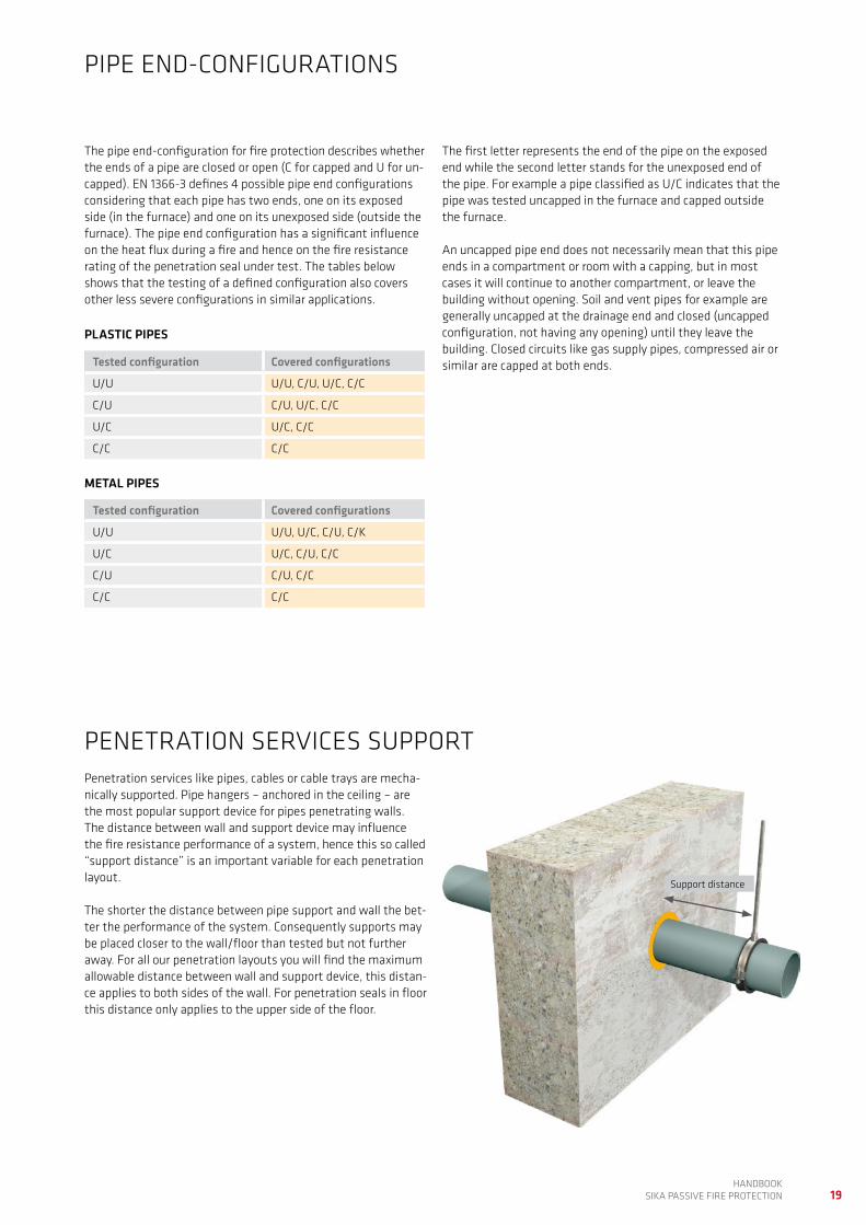
PENETRATION SERVICES SUPPORTPenetration services like pipes, cables or cable trays are mecha-nically supported. Pipe hangers – anchored in the ceiling – are the most popular support device for pipes penetrating walls. The distance between wall and support device may influence the fire resistance performance of a system, hence this so called “support distance” is an important variable for each penetration layout.
The shorter the distance between pipe support and wall the bet-ter the performance of the system. Consequently supports may be placed closer to the wall/floor than tested but not further away. For all our penetration layouts you will find the maximum allowable distance between wall and support device, this distan-ce applies to both sides of the wall. For penetration seals in floor this distance only applies to the upper side of the floor.
PIPE END-CONFIGURATIONS
Support distance
The pipe end-configuration for fire protection describes whether the ends of a pipe are closed or open (C for capped and U for un-capped). EN 1366-3 defines 4 possible pipe end configurations considering that each pipe has two ends, one on its exposed side (in the furnace) and one on its unexposed side (outside the furnace). The pipe end configuration has a significant influence on the heat flux during a fire and hence on the fire resistance rating of the penetration seal under test. The tables below shows that the testing of a defined configuration also covers other less severe configurations in similar applications.
PLASTIC PIPES
Tested configuration Covered configurations
U/U U/U, C/U, U/C, C/C
C/U C/U, U/C, C/C
U/C U/C, C/C
C/C C/C
Tested configuration Covered configurations
U/U U/U, U/C, C/U, C/K
U/C U/C, C/U, C/C
C/U C/U, C/C
C/C C/C
METAL PIPES
The first letter represents the end of the pipe on the exposed end while the second letter stands for the unexposed end of the pipe. For example a pipe classified as U/C indicates that the pipe was tested uncapped in the furnace and capped outside the furnace. An uncapped pipe end does not necessarily mean that this pipe ends in a compartment or room with a capping, but in most cases it will continue to another compartment, or leave the building without opening. Soil and vent pipes for example are generally uncapped at the drainage end and closed (uncapped configuration, not having any opening) until they leave the building. Closed circuits like gas supply pipes, compressed air or similar are capped at both ends.

20HANDBOOK SIKA PASSIVE FIRE PROTECTION
This book describes different applications of penetration seals around pipes, cables and cable trays. Each example shows only one utility or service pipe, whilst under certain conditions several services may be combined to pass through one large aperture:
For example with SikaSeal®-626 Fire Board and Sikacrete®-630 Fire, the maximum aperture size is stated for each different type of application. Within these limitations multiple services can be combined, provided that they are all based on the same
configuration (e.g. two boards in a flexible wall). The maximum aperture size as well as the resistance to fire rating of the combined seal will be no-better than the lowest size and rating of all of the individual seals included. The total cross section of all of the services combined must be ≤ 60% of the total aperture size (area). The minimum distances for sealing around and between each of the individual service pipes, as well as the distance to the edges of the aperture must be respected in all situations.
PIPE AND INSULATION MATERIAL
COMBINING MULTIPLE SERVICES IN ONE APERTURE
The variety of plastic materials used for combustible pipes and pipe insulations is wide. Many of these plastic types have dif-ferent physical characteristics (e.g. softening point or melting point) which means that pipes made from different materi-als will perform differently when exposed to fire. In order to minimise test effort without compromising on safety EN 1366-3 defines plastic materials which are covered if other, similar materials are tested.
Class Tested material Covered material
PVC PVC-U PVC-U, PVC-C
PP PP PP
PE PE-HD PE, ABS, SAN + PVC
Abbrev. Explanation
PVC Polyvinyl chloride
PVC-U Unplasticised PVC known as “hard PVC”
PVC-C Chlorinated PVC
PP Polypropylene
PE Polyethylene
PE-HD High density PE
SAN Styrene acrylonitrile copolymer
SAN + PVC Styrene copolymer blend material
X+Y+Z ≤ 0.6 (ab)


22HANDBOOK SIKA PASSIVE FIRE PROTECTION
Sika provides a full range of fire resistant products for linear seals. Some applications can be covered by several alterna-tive products, others – more specific ones – by just one. The following guide is intended to help you find the most efficient solution to any given application:
Firstly, use the diagram below starting with the column on the left (walls, floors/heads of walls or cavity barriers), wor-king left to right to select the relevant code (A – G) letter(s) in the right hand column.
Secondly, in the table below find the codes from the diagram and use the corresponding line(s) to the find the products that are suitable for your application. Then for full details please refer to the corresponding product page of this document.
Key Use Product Page
A Static joints in flexible walls* Sikacryl®-621 Fire 28
C Static joints in rigid walls* Sikacryl®-620 Fire 27
Sikacryl®-621 Fire 28
Sika® Backer Rod Fire 29 – 31
Sikasil®-670 Fire 24 – 25
Sika Boom®-400 Fire 32
Sikaflex®-400 Fire 26
D Movement joints in rigid walls Sikasil®-670 Fire 24 – 25
E Static joints in floors or head of wall applications* Sikacryl®-620 Fire 27
Sikacryl®-621 Fire 28
Sika® Backer Rod Fire 29 – 31
Sikasil®-670 Fire 24 – 25
F Movement joints in floors or head of wall applications Sikasil®-670 Fire 24 – 25
G Cavity barriers Sikacryl®-624 Fire 31
WALLS FLEXIBLE WALLS
RIGID FLOORS, HEAD OF WALLS
Static joints (Movement ≤± 7.5%)
A
Static joints (Movement ≤± 7.5%)
C, A, D
Static joints (Movement ≤± 7.5%)
E, F
Movement joints (Movement ≤± 25%)
G
RIGID WALLS
RIGID WALLS / FLOORS
Movement joints (Movement ≤± 25%)
–
Movement joints (Movement ≤± 25%)
D
Movement joints (Movement ≤± 25%)
F
FLOORS, HEAD OF WALLS
CAVITY BARRIERS
SELECTION GUIDE AND SOLUTIONS TO LINEAR SEALS
* Static joints can accomodate max. ± 7.5% movement (acc. FAD 350141-00-1106)

23HANDBOOK
SIKA PASSIVE FIRE PROTECTION
Product Description Typical uses Main advantages
Sikasil®-670 Fire Neutral cure, fire resistant silicone sealant
Static and elastic floor- and wall joints
Indoor and outdoor use
Compensates ± 25% movement also in case of fire (tested acc. EN 1366-4)
For wall joints – horizontal and vertical
For floor joints Can be used on various substrates
Sikacryl®-621 FirePhthalate-free, fire resistant acrylic sealant
Static floor and wall joints Indoor use
Easy to use, easy to clean System component used in con-junction with many products for penetration seals
Sikacryl®-620 FireFire resistant acrylic sealant
Static floor and wall joints Indoor use
Easy to use, easy to clean
Sika® Backer Rod FireMineral wool based, non-com-bustible, fire resistant backer rod used in combination with SikaHyflex®-250 Facade, Sikaflex® AT Connection or Sikaflex® PRO-3
Static floor and wall joints Indoor and outdoor use
For wall joints – horizontal and vertical
For floor joints Outstanding fire resistance even in single seal configuration
Sikaflex®-400 FireFire resistant PU sealant
Static floor and wall joints Indoor and outdoor use
For wall and floor joints Suitable for hot / humid climatic conditions
Sika Boom®-400 FireFire resistant expansion foam
Static floor and wall joints Indoor use
Tested for joints up to 45 mm width
High volume expansion Easy to apply
Sikacryl®-624 FireFire resistant acrylic sealant/coating
Static and elastic floor- and wall joints
Indoor use
Suitable for joint up to 200 mm width
Compensates ± 25% movement also in case of fire (tested acc. EN 1366-4)
Very easy to apply by pouring, spraying or brushing
PRODUCT OVERVIEW LINEAR SEALS

24HANDBOOK SIKA PASSIVE FIRE PROTECTION
Substrates Movement Configuration Joint width (mm)
Joint depth (mm)
Resistance Class
Concrete* / Concrete
± 25% 1 12 – 50 0.5 x width EI 240
± 25% 2 10 – 30 15 EI 45, E 180
± 25% 2 12 – 50 0.5 x width EI 30, E 240
± 25% 3 10 – 30 15 EI 45, E 60
± 25% 3 30 – 50 0.5 x width EI 45, E 60
± 7.5% 1 12 – 50 0.5 x width EI 240
± 7.5% 2 12 – 50 0.5 x width EI 60, E 240
± 7.5% 3 10 – 30 15 EI 60, E 240
± 7.5% 3 30 – 50 0.5 x width EI 45, E 180
Concrete* / Steel
± 7.5% 1 12 – 30 0.5 x width EI 60, E 240
± 7.5% 1 30 – 50 0.5 x width EI 90, E 240
± 7.5% 2 12 – 50 0.5 x width EI 15, E 240
Concrete* /Softwood
± 7.5% 1 12 – 50 0.5 x width EI 120
± 7.5% 2 12 – 50 0.5 x width EI 90
Concrete* /Hardwood
± 7.5% 1 12 – 30 0.5 x width EI 180
± 7.5% 1 30 – 50 0.5 x width EI 240
* Brickwork, concrete or aerated concrete with a density ≥ 760 kg/m3
Resistance to fire of horizontal linear seals in rigid walls (wall thickness ≥ 150 mm) sealed with Sikasil®-670 Fire. Tested acc. EN 1366-4 and classified acc. EN 13501-2/EAD 350141-00-1106.
Substrates Movement Configuration Joint width (mm)
Joint depth (mm)
Resistance Class
Concrete* / Concrete
± 25% 1 12 – 50 0.5 x width EI 180, E 240
± 25% 2 12 – 50 0.5 x width EI 60, E 120
± 25% 3 10 – 30 15 EI 45, E 60
± 25% 3 30 – 50 0.5 x width EI 45, E 60
± 7.5% 1 12 – 50 0.5 x width EI 240
± 7.5% 2 12 – 50 0.5 x width EI 60, E 240
± 7.5% 3 10 – 30 15 EI 60, E 180
± 7.5% 3 30 – 50 0.5 x width EI 60, E 90
* Brickwork, concrete or aerated concrete with a density ≥ 760 kg/m3
CONFIGURATIONS
1. Double seal
2. Single seal, unexposed side
3. Single seal, exposed side
CONFIGURATIONS
1. Double seal
3. Single seal, exposed side
2. Single seal, unexposed side
Sikasil®-670 Fire
Resistance to fire of vertical linear seals in rigid walls (wall thickness ≥ 150 mm) sealed with Sikasil®-670 Fire. Tested acc. EN 1366-4 and classified acc. EN 13501-2/EAD 350141-00-1106.

25HANDBOOK
SIKA PASSIVE FIRE PROTECTION
CONFIGURATIONS
1. Double seal
2. Single seal, unexposed side
3. Single seal, exposed side
Sikasil®-670 Fire
Resistance to fire of linear seals in rigid floors (floor thickness ≥ 150 mm) sealed with Sikasil®-670 Fire. Tested acc. EN 1366-4 and classified acc. EN 13501-2/EAD 350141-00-1106.
Substrates Movement Configuration Joint width (mm)
Joint depth (mm)
Resistance Class
Concrete* / Concrete
± 25% 1 12 – 50 0.8 x width EI 180, E 240
± 25% 2 12 – 50 0.8 x width EI 60, E 240
± 25% 3 12 – 50 0.8 x width EI 60, E 90
± 7.5% 1 12 – 50 0.8 x width EI 240
± 7.5% 2 12 – 30 0.8 x width EI 120, E 240
± 7.5% 2 30 – 50 0.8 x width EI 60, E 240
± 7.5% 3 12 – 50 0.8 x width EI 60
Concrete* /Steel
± 7.5% 1 12 – 50 0.8 x width EI 60, E 240
± 7.5% 2 12 – 50 0.8 x width EI 60, E 90
± 7.5% 3 12 – 50 0.8 x width EI 60, E 90
* Brickwork, concrete or aerated concrete with a density ≥ 760 kg/m3

26HANDBOOK SIKA PASSIVE FIRE PROTECTION
Resistance to fire of linear seals in rigid floors (floor thickness ≥ 200 mm) sealed with Sikaflex®-400 Fire. Tested acc. Tested acc. AS 1530.4 / EN 1366-4 and classified acc. EN 13501-2.
CONFIGURATIONS
Sikaflex®-400 Fire
Resistance to fire of vertical linear seals in rigid walls (wall thickness ≥ 150 mm) sealed with Sikaflex®-400 Fire. Tested acc. AS 1530.4 / EN 1366-4 and classified acc. EN 13501-2.
Substrates Configuration Joint width (mm)
Joint depth (mm)
Resistance Class***
Concrete**/ Concrete 1 25 10 EI 180, E 240
2 10 – 40 0.5 x width EI 120, E 240
Concrete*/ Concrete 2 10 – 40 0.5 x width EI 120
* Brickwork, concrete or aerated concrete with a density ≥ 760 kg/m3 ** Precast concrete *** EI 180, E 240 acc. EN 13501-2 is the equivalent of “-/240/180” acc. AS 1530.4
CONFIGURATIONS
1. Double seal
2. Single seal, unexposed side
1. Double seal
2. Single seal, unexposed side
* Brickwork, concrete or aerated concrete with a density ≥ 760 kg/m3
Substrates Configuration Joint width (mm)
Joint depth (mm)
Resistance Class***
Concrete*/ Concrete 1 12 – 40 0.8 x width EI 240
2 12 – 40 0.8 x width EI 120
27HANDBOOK
SIKA PASSIVE FIRE PROTECTION
CONFIGURATIONS
1. Double seal
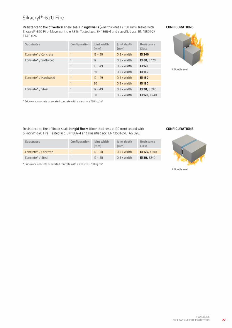
CONFIGURATIONSResistance to fire of linear seals in rigid floors (floor thickness ≥ 150 mm) sealed with Sikacryl®-620 Fire. Tested acc. EN 1366-4 and classified acc. EN 13501-2/ETAG 026.
Substrates Configuration Joint width (mm)
Joint depth (mm)
Resistance Class
Concrete* / Concrete 1 12 – 50 0.5 x width EI 120, E240
Concrete* / Steel 1 12 – 50 0.5 x width EI 30, E240
* Brickwork, concrete or aerated concrete with a density ≥ 760 kg/m3
1. Double seal
Sikacryl®-620 Fire
Resistance to fire of vertical linear seals in rigid walls (wall thickness ≥ 150 mm) sealed with Sikacryl®-620 Fire. Movement ≤ ± 7.5%. Tested acc. EN 1366-4 and classified acc. EN 13501-2/ETAG 026.
Substrates Configuration Joint width (mm)
Joint depth (mm)
Resistance Class
Concrete* / Concrete 1 12 – 50 0.5 x width EI 240
Concrete* / Softwood 1 12 0.5 x width EI 60, E 120
1 13 – 49 0.5 x width EI 120
1 50 0.5 x width EI 180
Concrete* / Hardwood 1 12 – 49 0.5 x width EI 180
1 50 0.5 x width EI 180
Concrete* / Steel 1 12 – 49 0.5 x width EI 90, E 240
1 50 0.5 x width EI 120, E240
* Brickwork, concrete or aerated concrete with a density ≥ 760 kg/m3

28HANDBOOK SIKA PASSIVE FIRE PROTECTION
Substrates Wall thickness (mm)
Configu-ration
Joint width (mm)
Joint depth (mm)
Resistance Class
Concrete* / Concrete
≥ 100 3 8 – 20 10 EI 45, E 120
≥ 100 3 8 – 50 25 EI 60, E 120
≥ 150 1 8 – 50 20 EI 120, E 240
≥ 150*** 2 8 – 50 5 EI 120, E 240
≥ 150 1 8 – 50 25 EI 240
Concrete* / Steel
≥ 100 3 8 – 20 10 EI 20, E 120
≥ 100 3 8 – 50 25 EI 30, E 45
≥ 150**** 1 8 – 50 30 EI 60, E 240
Concre-te* /Softwood
≥ 100 3 8 – 20 10 EI 20, E 30
≥ 100 3 8 – 50 25 EI 45
≥ 150**** 1 8 – 50 30 EI 60
Gypum walls**/ Concrete*
≥ 120 4 8 – 20 12.5 EI 120
≥ 120 1 8 – 20 12.5 EI 120
* Brickwork, concrete or aerated concrete with a density ≥ 670 kg/m3 ** 2 Layers of gypsum board (2 x 15 mm on each side)*** Backed with ≥ 60 kg/3 mineral wool, ≥ 75 mm deep**** Backed with ≥ 45 kg/3 mineral wool, ≥ 40 mm deep
Resistance to fire of linear joints in floors as well as head of walls (wall thickness ≥ 150 mm) sealed with Sikacryl®-621 Fire. Movement ≤ ± 7.5%. Tested acc. EN 1366-4 and classified acc. EN 13501-2/EAD 350141-00-1106.
Substrates Configu-ration
Joint width (mm)
Joint depth (mm)
Resistance Class
Concrete* /Concrete
3/6 8 – 20 10 EI 45, E 240
3/6 8 – 50 25 EI 90, E 240
1/4 8 – 50 20 EI 120, E 240
2/5 8 – 50 5*** EI 120, E 240
Concrete* /Steel
3/6 8 – 20 10 EI 20, E 120
3/6 8 – 50 25 EI 90, E 240
Concrete* /Softwood
3/6 8 – 20 10 EI 30
3/6 8 – 50 25 EI 45
* Brickwork, concrete or aerated concrete with a density ≥ 760 kg/m3 *** Backed with ≥ 60 kg/3 mineral wool, ≥ 75 mm deep
Sikacryl®-621 Fire
Resistance to fire of vertical linear joints in rigid and flexible walls sealed with Sikacryl®-621 Fire. Movement ≤ ± 7.5%. Tested acc. EN 1366-4 and classified acc. EN 13501-2/EAD 350141-00-1106.
4. Double seal
5. Single seal, unexposed side
CONFIGURATIONS
1. Double seal
2. Single seal, unexposed side
3. Single seal, exposed side 6. Single seal, exposed side
CONFIGURATIONS
1. Double seal 3. Single seal, exposed side
2. Single seal, unexposed side 4. Double seal

29HANDBOOK
SIKA PASSIVE FIRE PROTECTION
Sika® Backer Rod Fire
Use of Sika® Backer Rod Fire depending on the joint width
Nom
inal
dia
met
er o
f Sik
a® B
acke
r Rod
Fire
(mm
)
Joint width (mm)
0
60
50
40
30
20
15
127
9
12
16
10.2
12.7
17
25.5
42.5
5 10 15 20 25 30 35 40 45 50 55
24
32
40 51
34
Sika® Backer Rod Fire is available in seven different nominal diameters (see y-axis of the diagram) Refer to the number at the right edge of the yellow bar in the diagram, as each diameter of Sika® Backer Rod Fire may only be used for nominal joint widths below this value. The number at the left edge of
the bar refers to the lower nominal joint width limit, since Sika® Backer Rod Fire can only be compressed to a certain degree. For example, for a nominal 50 mm diameter Sika® Backer Rod Fire, the lower limit threshold joint width is 32 mm, and the maximum joint width is 42.5 mm.

30HANDBOOK SIKA PASSIVE FIRE PROTECTION
Sika® Backer Rod Fire
Resistance to fire of vertical linear seals in rigid walls* (wall thickness ≥ 150 mm) se-aled with Sika® Backer Rod Fire combined with SikaHyflex®-250 Facade, Sikaflex® AT Connection or Sikaflex® PRO-3. Movement ≤ ± 7.5%. Tested acc. EN 1366-4 and classi-fied acc. EN 13501-2/EAD 350141-00-1106.
Resistance to fire of horizontal linear seals in rigid walls* (wall thickness ≥ 150 mm) sealed with Sika® Backer Rod Fire combined with SikaHyflex®-250 Facade, Sikaflex® AT Connection. Movement ≤ ± 7.5%. Tested acc. EN 1366-4 and classified acc. EN 13501-2/EAD 350141-00-116.
Sealant Configuration Joint width (mm)
Joint depth (mm)
Resistance Class
SikaHyflex®-250 Facade
1 7 – 51 0.5 x width EI 240
2 7 – 51 0.5 x width EI 180, E 240
3 7 – 51 0.5 x width EI 120, E 240
Sikaflex® AT Connection
1 7 – 51 0.5 x width EI 240
2 7 – 51 0.5 x width EI 180, E 240
3 7 – 51 0.5 x width EI 180, E 240
Sikaflex® PRO-3 2 7 – 51 0.5 x width EI 180, E 240
3 7 – 51 0.5 x width EI 45, E 120
* Brickwork, concrete or aerated concrete with a density ≥ 760 kg/m3
Sealant Configuration Joint width (mm)
Joint depth (mm)
Resistance Class
SikaHyflex®-250 Facade
2 7 – 51 0.5 x width EI 240
3 7 – 51 0.5 x width EI 90, E 180
Sikaflex® AT Connection
2 7 – 51 0.5 x width EI 240
3 7 – 51 0.5 x width EI 120, E 240
* Brickwork, concrete or aerated concrete with a density ≥ 760 kg/m3
2. Single seal, unexposed side
3. Single seal, exposed side
CONFIGURATIONS
1. Double seal
3. Single seal, exposed side
2. Single seal, unexposed side
CONFIGURATIONS

31HANDBOOK
SIKA PASSIVE FIRE PROTECTION
Sika® Backer Rod Fire
Resistance to fire of linear joints in rigid floors* (floor thickness ≥ 200 mm) sealed with Sika® Backer Rod Fire combined with SikaHyflex®-250 Facade**, Sikaflex® AT Connection** or Sikaflex® PRO-3. Movement ≤ ± 7.5%. Tested acc. EN 1366-4 and classified acc. EN 13501-2/EAD 350141-00-1106.
Substrates Configuration Joint width (mm)
Joint depth (mm)
Resistance Class
Sikaflex® PRO-3 1 7 – 51 0.8 x width EI 240
2 7 – 51 0.8 x width EI 240
3 7 – 51 0.8 x width EI 60, E 240
SikaHyflex®-250 Facade
1** 7 – 51 0.8 x width EI 240
2** 7 – 51 0.8 x width EI 240
3 7 – 51 0.8 x width EI 120, E 180
Sikaflex® AT Connection
1** 7 – 51 0.8 x width EI 240
2** 7 – 51 0.8 x width EI 240
3 7 – 51 0.8 x width EI 120, E 180
* Brickwork, concrete or aerated concrete with a density ≥ 760 kg/m3
** Not approved for pedestrian walkways acc. EN 15651-4 in the European Union
CONFIGURATIONS
1. Double seal
2. Single seal, unexposed side
3. Single seal, exposed side

32HANDBOOK SIKA PASSIVE FIRE PROTECTION
Sika Boom®-400 Fire
Resistance to fire of vertical linear joints in rigid walls* (wall thickness ≥ 200 mm) sea-led with Sika Boom®-400 Fire. Movement ± 7.5%. Tested acc. EN 1366-4 and classified acc. EN 13501-2.
CONFIGURATIONS
2. Single seal, unexposed side
Configuration Application type
Joint width (mm)
Joint depth (mm)
ResistanceClass
2 gun ≤10 200 EI 240
2 gun ≤30 180 EI 120
2 gun ≤45 180 EI 60
2 gun ≤20 120 EI 240
2 gun ≤35 120 EI 90
2 nozzle ≤10 200 EI 240
2 nozzle ≤30 160 EI 120
2 nozzle ≤45 160 EI 90
2 nozzle ≤20 100 EI 180
2 nozzle ≤35 100 EI 60
* Brickwork, concrete or aerated concrete with a density ≥ 760 kg/m3
Resistance to fire of linear joints in floors* (floor thickness ≥ 200 mm) sealed with Sika Boom®-400 Fire. Movement ± 7.5%. Tested acc. EN 1366-4 and classified acc. EN 13501-2.
CONFIGURATIONS
2. Single seal, unexposed side
Configuration Application type
Joint width (mm)
Joint depth (mm)
ResistanceClass
2 gun ≤10 200 EI 240
2 gun ≤30 180 EI 120
2 gun ≤45 180 EI 60
2 gun ≤20 120 EI 180
2 gun ≤35 120 EI 60
2 nozzle ≤10 200 EI 240
2 nozzle ≤30 160 EI 90
2 nozzle ≤45 160 EI 60
2 nozzle ≤20 100 EI 180
2 nozzle ≤35 100 EI 60
* Brickwork, concrete or aerated concrete with a density ≥ 760 kg/m3

33HANDBOOK
SIKA PASSIVE FIRE PROTECTION
Sikacryl®-624 Fire
Resistance to fire of cavity barriers in floors (floor thickness ≥ 150 mm) sealed with Sikacryl®-624 Fire. Tested acc. EN 1366-4 and classified acc. EN 13501-2/EAD 350141-00-1106.
CONFIGURATIONS
1. Cavity barrier in floor
2. Cavity barrier etween wall and floor
Substrates Movement Configuration Joint width (mm)
Joint depth (mm)
Resistance Class
Concrete* / Concrete
± 25% 1 10 – 200** 1*** EI 180, E 240
± 25% 2 10 – 200** 1*** EI 180, E 240
* Brickwork, concrete or aerated concrete with a density ≥ 760 kg/m3 ** Backed with ≥ 80 kg/3 mineral wool, ≥ 100 mm deep*** ≥ 1 mm dry film thickness, equals to ≥ 2 mm wet film thickness

34HANDBOOK SIKA PASSIVE FIRE PROTECTION
SELECTION GUIDE AND SOLUTIONS TO PENETRATION SEALSSika offers a full range of fire resistant products for penetration seals. Some applications can be covered by several products, others – more specific ones – just by one. The following guide will help you to select the best solution to a given application.
How to use this selection guideUse the below diagram to find the relevant type of layout for your application and browse to corresponding page. There you
will find an overview to all applications covering a certain type of penetration, followed by detailed descriptions of each layout. Before choosing one specific layout check all other layouts of the same penetration type (e.g. all layouts for insulated metal pipes).
WALL
SEPARATING ELEMENT PENETRATION SERVICE TYPE PAGEAPERTURE SIZE*
FLOOR
LARGE APERTURE
LARGE APERTURE
SMALL APERTURE
SMALL APERTURE
Metal pipes insulated
Metal pipes uninsulated
Plastic and MLC pipes
Cables, cable trays and conduits
Metal pipes insulated
Metal pipes uninsulated
Plastic and MLC pipes
Cables, cable trays and conduits
36
44
48
54
**
76
80
86
Metal pipes insulated
Metal pipes uninsulated
Plastic and MLC pipes
Cables, cable trays and conduits
Metal pipes insulated
Metal pipes uninsulated
Plastic and MLC pipes
Cables, cable trays and conduits
60
64
68
74
90
**
92
**
* A Large apertures is an opening clearly larger than the penetration service and hence a large surface must be sealed, generally with an insulation board (SikaSeal®-626 Fire Board) or a compound (Sikacrete®-630 Fire). A small aperture is ± of the same size as the penetration service and only limited surface must be sealed. Mostly small apertures are core drilled holes for pipes or cables.
** Not covered by this handbook
Small aperture (core drilled hole)Large aperture

35HANDBOOK
SIKA PASSIVE FIRE PROTECTION
PRODUCT OVERVIEW PENETRATION SEALS
Product Description Typical uses Main advantages
SikaSeal®-623 FireIntumescent, fire resistant seal-ant
Combustible pipes, mainly small diameters
Highly intumescent – volume expansion 20 times original size
Easy to apply
Sikacryl®-625 FireFire resistant acrylic coating
Edge protection and touch-up on SikaSeal®-626 Fire Board
Easy to apply and clean
SikaSeal®-626 Fire BoardMineral wool based, fire resistant coated board
All kind of penetrations in walls and floors; also in combination with other products
Extremely versatile For face-fit and internal fit instal-lations
Can be combined with many other products
SikaSeal®-627 Fire Collar Intumescent, fire resistant pipe collar
Combustible pipes in walls and floors; all diameters.
Face-fit installation
Highly intumescent – volume expansion 20 times original size
Flexible design enables installati-on in confined spaces
Easy to apply – 1 part, 3 fixings for all sizes
SikaSeal®-628 Fire WrapIntumescent, fire resistant pipe wrap
Combustible pipes in walls and floors; all diameters.
Internal-fit installation
Highly intumescent – volume expansion 20 times original size
Ready to use, pre-cut strips for most pipe diameters
Invisible installation in walls and floors
SikaSeal®-629 Fire Wrap Intumescent, fire resistant pipe wrap on a roll
Combustible pipes in walls and floors, all diameters.
Internal-fit installation
Highly intumescent – volume expansion 20 times original size
Cut and use direct from roll Invisible installation in walls and floors
Sikacrete®-630 FireLoad bearing, fire resistant com-pound
All kind of load bearing penetra-tions in floors
Excellent load bearing properties Self-supporting in floor penetra-tions up to 1.8 x 1.8 m
Fast setting, no loss of volume

36HANDBOOK SIKA PASSIVE FIRE PROTECTION
Short description Products Code Page
Insulated steel and copper pipes in flexible and rigid wallsGlass wool pipe insulationInsulated walls, lined aperturesInternal fit board installation
SikaSeal®-626 Fire BoardSikacryl®-621 FireSikaSeal®-623 Fire
626.5 37
Insulated steel and copper pipes in flexible and rigid wallsGlass wool pipe insulationInsulated walls, lined and unlined aperturesInternal fit board installation
SikaSeal®-626 Fire BoardSikacryl®-621 Fire
626.6 38
Insulated steel and copper pipes in flexible and rigid wallsK-flex pipe insulationInsulated walls, lined and unlined aperturesInternal fit board installation
SikaSeal®-626 Fire BoardSikacryl®-621 FireSikaSeal®-629 Fire Wrap
626.7 39
Insulated steel and copper pipes in flexible and rigid wallsKingspan Kooltherm pipe insulationInsulated walls, lined and unlined aperturesInternal fit board installation.
SikaSeal®-626 Fire BoardSikacryl®-621 FireSikaSeal®-629 Fire Wrap
626.8 40
Insulated steel and copper pipes in flexible and rigid wallsK-flex pipe insulationInsulated and uninsulated walls, lined and unlined aperturesFace fit (pattress fit) board installation.
SikaSeal®-626 Fire BoardSikacryl®-621 FireSikacryl®-625 Fire (Sikacryl®-621 Fire alternatively)SikaSeal®-629 Fire Wrap
626.10 41
Insulated steel and copper pipes in flexible and rigid wallsKingspan Kooltherm pipe insulationInsulated and uninsulated walls, lined and unlined aperturesFace fit (pattress fit) board installation.
SikaSeal®-626 Fire BoardSikacryl®-621 FireSikacryl®-625 Fire (Sikacryl®-621 Fire alternatively)SikaSeal®-629 Fire Wrap
626.11 42
INSULATED METAL PIPES IN WALLS, LARGE APERTURES

37HANDBOOK
SIKA PASSIVE FIRE PROTECTION
3
22
1
Layout: 626.5/626.C
PRODUCTS, MATERIALS1. SikaSeal®-626 Fire Board 2. Sikacryl®-621 Fire3. SikaSeal®-623 Fire
CLASSIFICATIONEI 60 U/C
DETAILS Wall: Thickness ≥ 100 mm, ≥ 2 layers of gypsum board each side (≥ 25 mm in total each side) on a steel or timber stud
Pipes: Diameter ≤ 159 mm, wall thick-ness 2.3 – 14.2 mm steel and copper or metals with higher melting point and/or lower thermal conductivity
Pipe insulation: Glass wool, stone wool or ceramic wool, density ≥ 80 kg/ m3, thickness 30 mm, CS (continuous sustained)
SikaSeal®-626 Fire Board internal fit, installed flush on both sides of the wall
15 mm annular space around pipes sealed with SikaSeal®-623 Fire, ≥ 15 mm deep, double seal
Sikacryl®-621 Fire between board and gypsum board
Aperture size ≤ 730 x 1,200 mm Distance between pipes (sealant) ≥ 100 mm
Distance between aperture edge and pipes (sealant) ≥ 100 mm
Distance between wall and pipe sup-port ≤ 250 mm
Covers flexible walls (insulated, lined) as well as rigid walls
INSTALLATION INSTRUCTIONSRefer to the relevant Sika method state-ment(s)
INSULATED METAL PIPES IN FLEXIBLE AND RIGID WALLS

38HANDBOOK SIKA PASSIVE FIRE PROTECTION
Layout: 626.6/626.D
PRODUCTS, MATERIALS1. SikaSeal®-626 Fire Board 2. Sikacryl®-621 Fire
CLASSIFICATIONEI 45, E 120 C/U
DETAILS Wall: Thickness ≥ 100 mm, ≥ 2 layers of gypsum board each side (≥ 25 mm in total each side) on a steel or timber stud
Pipes: Diameter ≤ 159 mm, wall thick-ness 1.2 – 14.2 mm steel and copper or metals with higher melting point and/or lower thermal conductivity
Pipe insulation: Glass wool, stone wool or ceramic wool, density ≥ 30 kg/ m3, thickness 25 mm, CS (continuous sustained)
SikaSeal®-626 Fire Board internal fit, installed flush on both sides of the wall
Sikacryl®-621 Fire between abutting materials
Aperture size ≤ 730 x 1,200 mm Distance between pipes (sealant) ≥ 100 mm
Distance between aperture edge and pipes (sealant) ≥ 100 mm
Distance between wall and pipe sup-port ≤ 400 mm
Covers flexible walls (insulated, lined and unlined) as well as rigid walls
INSTALLATION INSTRUCTIONSRefer to the relevant Sika method state-ment(s)
INSULATED METAL PIPES IN FLEXIBLE AND RIGID WALLS
2
22
1

39HANDBOOK
SIKA PASSIVE FIRE PROTECTION
Layout: 626.7/626.E
PRODUCTS, MATERIALS1. SikaSeal®-626 Fire Board 2. Sikacryl®-621 Fire3. SikaSeal®-629 Fire Wrap
CLASSIFICATIONEI 60, E 120 C/U (for K-FLEX pipes)EI 60, E 120 C/U (for glass wool insulated pipes)
DETAILS Wall: Thickness ≥ 100 mm, ≥ 2 layers of gypsum board each side (≥ 25 mm in total each side) on a steel or timber stud
Pipes: Diameter ≤ 159 mm, wall thick-ness 1.2 – 14.2 mm steel and copper or metals with higher melting point and/or lower thermal conductivity
Pipe insulation: K-FLEX ST foam insu-lation, thickness 13 – 25 mm; alternati-vely glass wool, stone wool or ceramic wool, density ≥ 30 kg/m3, thickness 50 mm, CS (continuous sustained)
SikaSeal®-626 Fire Board internal fit, installed flush on both sides of the wall
5 mm annular space around pipes, 2 layers of SikaSeal®-629 Fire Wrap, Sikacryl®-621 Fire 5 mm deep on both sides
Sikacryl®-621 Fire between board and gypsum board
Aperture size ≤ 730 x 1,200 mm Distance between pipes (sealant) ≥ 100 mm
Distance between aperture edge and pipes (sealant) ≥ 100 mm
Distance between wall and pipe sup-port ≤ 400 mm
Covers flexible walls (insulated, lined and unlined) as well as rigid walls
INSTALLATION INSTRUCTIONSRefer to the relevant Sika method state-ment(s)
INSULATED METAL PIPES IN FLEXIBLE AND RIGID WALLS
33
22
2
1

40HANDBOOK SIKA PASSIVE FIRE PROTECTION
Layout: 626.8/626.E
PRODUCTS, MATERIALS1. SikaSeal®-626 Fire Board 2. Sikacryl®-621 Fire3. SikaSeal®-629 Fire Wrap
CLASSIFICATIONEI 60, E 120 C/U
DETAILS Wall: Thickness ≥ 100 mm, ≥ 2 layers of gypsum board each side (≥ 25 mm in total each side) on a steel or timber stud
Pipes: Diameter ≤ 108 mm, wall thick-ness 1.2 – 14.2 mm steel and copper or metals with higher melting point and/or lower thermal conductivity
Pipe insulation: Kingspan Kooltherm FM, CS (continuous sustained)
SikaSeal®-626 Fire Board internal fit, installed flush on both sides of the wall
5 mm annular space around pipes, 2 layers of SikaSeal®-629 Fire Wrap, Sikacryl®-621 Fire 5 mm deep on both sides
Sikacryl®-621 Fire between board and gypsum board
Aperture size ≤ 730 x 1,200 mm Distance between pipes (sealant) ≥ 100 mm
Distance between aperture edge and pipes (sealant) ≥ 100 mm
Distance between wall and pipe sup-port ≤ 400 mm
Covers flexible walls (insulated, lined and unlined) as well as rigid walls
INSTALLATION INSTRUCTIONSRefer to the relevant Sika method state-ment(s)
INSULATED METAL PIPES IN FLEXIBLE AND RIGID WALLS
33
22
2
1

41HANDBOOK
SIKA PASSIVE FIRE PROTECTION
Layout: 626.10/626.G
PRODUCTS, MATERIALS1. SikaSeal®-626 Fire Board 2. Sikacryl®-621 Fire3. Sikacryl®-625 Fire (Sikacryl®-621 Fire
alternatively)4. SikaSeal®-629 Fire Wrap
CLASSIFICATIONEI 90, E 120 C/U
DETAILS Wall: Thickness ≥ 100 mm, ≥ 2 layers of gypsum board each side (≥ 25 mm in total each side) on a steel or timber stud
Pipes: diameter ≤ 159 mm, wall thick-ness 1.2 – 14.2 mm steel and copper or metals with higher melting point and/or lower thermal conductivity
Pipe insulation: K-FLEX ST foam insulation, thickness 13 – 25 mm; alternatively glass wool, stone wool or ceramic wool, density ≥ 30 kg/m3, thickness 25 – 50 mm, CS (continuous sustained)
SikaSeal®-626 Fire Board face fit (pattress fit) installed on both sides of the wall
Edge surfaces of boards coated with Sikacryl®-625 Fire or Sikacryl®-621 Fire
Overlap between board and wall ≥ 100 mm
5 mm annular space around pipes, 2 layers of SikaSeal®-629 Fire Wrap, Sikacryl®-621 Fire 5 mm deep on both sides
Sikacryl®-621 Fire between board and wall
Aperture size ≤ 730 x 1,200 mm Distance between pipes (wrap) ≥ 100 mm
Distance between aperture edge and pipes (wrap) ≥ 100 mm
Distance between wall and pipe sup-port ≤ 400 mm
Covers flexible walls (insulated and uninsulated, lined and unlined) as well as rigid walls
INSTALLATION INSTRUCTIONSRefer to the relevant Sika method state-ment(s)
INSULATED METAL PIPES IN FLEXIBLE AND RIGID WALLS
2
2
3
1
4
4
3

Layout: 626.11/626.G
PRODUCTS, MATERIALS1. SikaSeal®-626 Fire Board 2. Sikacryl®-621 Fire3. Sikacryl®-625 Fire
(Sikacryl®-621 Fire alternatively)4. SikaSeal®-629 Fire Wrap
CLASSIFICATIONEI 90, E 120 C/U
DETAILS Wall: Thickness ≥ 100 mm, ≥ 2 layers of gypsum board each side (≥ 25 mm in total each side) on a steel or timber stud
Pipes: diameter ≤ 108 mm, wall thick-ness 1.2 – 14.2 mm steel and copper or metals with higher melting point and/or lower thermal conductivity
Pipe insulation: Kingspan Kooltherm FM, CS (continuous sustained)
SikaSeal®-626 Fire Board face fit (pattress fit) installed on both sides of the wall
Edge surfaces of boards coated with Sikacryl®-625 Fire or Sikacryl®-621 Fire
Overlap between board and wall ≥ 100 mm
5 mm annular space around pipes, 2 layers of SikaSeal®-629 Fire Wrap, Sikacryl®-621 Fire 5 mm deep on both sides
Sikacryl®-621 Fire between board and wall
Aperture size ≤ 730 x 1,200 mm Distance between pipes (wrap) ≥ 100 mm
Distance between aperture edge and pipes (wrap) ≥ 100 mm
Distance between wall and pipe sup-port ≤ 400 mm
Covers flexible walls (insulated and uninsulated, lined and unlined) as well as rigid walls
INSTALLATION INSTRUCTIONSRefer to the relevant Sika method state-ment(s)
INSULATED METAL PIPES IN FLEXIBLE AND RIGID WALLS
2
2
1
4
4
3
3
42HANDBOOK SIKA PASSIVE FIRE PROTECTION

43HANDBOOK
SIKA PASSIVE FIRE PROTECTION

44HANDBOOK SIKA PASSIVE FIRE PROTECTION
UNINSULATED METAL PIPES IN WALLS, LARGE APERTURES
Short description Products Code Page
Uninsulated steel and copper pipes in flexible and rigid wallsInsulated walls, lined and unlined aperturesInternal fit board installation
SikaSeal®-626 Fire BoardSikacryl®-621 FirePipe insulation
626.2 45
Uninsulated steel pipes in flexible and rigid wallsInsulated walls, lined and unlined aperturesInternal fit board installation.
SikaSeal®-626 Fire BoardSikacryl®-621 FireSikacryl®-625 Fire
626.3 46
Uninsulated steel pipes in flexible and rigid wallsInsulated walls, lined and unlined aperturesInternal fit board installation
SikaSeal®-626 Fire BoardSikacryl®-621 FireSikacryl®-625 Fire
626.4 47

45HANDBOOK
SIKA PASSIVE FIRE PROTECTION
Layout: 626.2/626.A
PRODUCTS, MATERIALS1. SikaSeal®-626 Fire Board 2. Sikacryl®-621 Fire3. Pipe insulation
CLASSIFICATIONEI 45 C/U
DETAILS Wall: Thickness ≥ 100 mm, ≥ 2 layers of gypsum board each side (≥ 25 mm in total each side) on a steel or timber stud
Pipes: Diameter ≤ 324 mm, wall thickness 14.2 – 16 mm, steel or metals with higher melting point and/or lower thermal conductivity
Pipe insulation: Stone wool, density ≥ 45 kg/m3, thickness ≥ 40 mm, length ≥ 400 mm, both sides of the wall, LI (local interrupted)
SikaSeal®-626 Fire Board internal fit, installed flush on both sides of the wall
Sikacryl®-621 Fire between abutting materials
Aperture size ≤ 730 x 1,200 mm Distance between pipes ≥ 0 mm Distance between aperture edge and insulation ≥ 50 mm
Distance between wall and pipe sup-port ≤ 400 mm
Covers flexible walls (insulated, lined and unlined) as well as rigid walls
INSTALLATION INSTRUCTIONSRefer to the relevant Sika method state-ment(s)
22
3
1
3
UNINSULATED METAL PIPES IN FLEXIBLE AND RIGID WALLS

46HANDBOOK SIKA PASSIVE FIRE PROTECTION
Layout: 626.3/626.B
PRODUCTS, MATERIALS1. SikaSeal®-626 Fire Board 2. Sikacryl®-621 Fire3. Sikacryl®-625 Fire
CLASSIFICATIONEI 45, E 120 C/U
DETAILS Wall: Thickness ≥ 100 mm, ≥ 2 layers of gypsum board each side (≥ 25 mm in total each side) on a steel or timber stud
Pipes: Diameter ≤ 159 mm wall thick-ness 1.2 – 14.2 mm, steel and copper or metals with higher melting point and/or lower thermal conductivity
Pipe insulation: Sikacryl®-625 Fire, thickness ≥ 2 mm, length ≥ 400 mm, both sides of the wall, LI (local interrupted)
SikaSeal®-626 Fire Board internal fit, installed flush on both sides of the wall
Sikacryl®-621 Fire between abutting materials
Aperture size ≤ 730 x 1,200 mm Distance between pipes ≥ 0 mm Distance between aperture edge and insulation ≥ 50 mm
Distance between wall and pipe sup-port ≤ 400 mm
Covers flexible walls (insulated, lined and unlined) as well as rigid walls
INSTALLATION INSTRUCTIONSRefer to the relevant Sika method state-ment(s)
UNINSULATED METAL PIPES IN FLEXIBLE AND RIGID WALLS
22
3
1
3

47HANDBOOK
SIKA PASSIVE FIRE PROTECTION
3
1
3
22
Layout: 626.4/626.B
PRODUCTS, MATERIALS1. SikaSeal®-626 Fire Board 2. Sikacryl®-621 Fire3. Sikacryl®-625 Fire
CLASSIFICATIONEI 30, E 120 C/U
DETAILS Wall: Thickness ≥ 100 mm, ≥ 2 layers of gypsum board each side (≥ 25 mm in total each side) on a steel or timber stud
Pipes: Diameter ≤ 324 mm, wall thickness 14.2 – 16 mm steel or metals with higher melting point and/or lower thermal conductivity
Pipe insulation: Sikacryl®-625 Fire, thickness ≥ 2 mm, length ≥ 400 mm, both sides of the wall, LI (local interrupted)
SikaSeal®-626 Fire Board internal fit, installed flush on both sides of the wall
Sikacryl®-621 Fire between abutting materials
Aperture size ≤ 730 x 1,200 mm Distance between pipes ≥ 0 mm Distance between aperture edge and insulation ≥ 50 mm
Distance between wall and pipe sup-port ≤ 400 mm
Covers flexible walls (insulated, lined and unlined) as well as rigid walls
INSTALLATION INSTRUCTIONSRefer to the relevant Sika method state-ment(s)
UNINSULATED METAL PIPES IN FLEXIBLE AND RIGID WALLS

48HANDBOOK SIKA PASSIVE FIRE PROTECTION
Short description Products Code Page
Plastic pipes in flexible and rigid wallsInsulated walls, lined and unlined aperturesInternal fit board installation
SikaSeal®-626 Fire BoardSikacryl®-621 FireSikaSeal®-627 Fire Collar
627.5 49
Plastic pipes in flexible and rigid wallsInsulated and uninsulated walls, lined and unlined aperturesFace fit (pattress fit) board installation
SikaSeal®-626 Fire BoardSikacryl®-621 FireSikacryl®-625 Fire (Sikacryl®-621 Fire alternatively)SikaSeal®-627 Fire Collar
627.6 50
Plastic pipes in flexible and rigid wallsInsulated and uninsulated walls, lined and unlined aperturesFace fit (pattress fit) board installation
SikaSeal®-626 Fire BoardSikacryl®-621 FireSikacryl®-625 Fire (Sikacryl®-621 Fire alternatively)SikaSeal®-628 Fire Wrap (SikaSeal®-629 Fire Wrap alternatively)
626.13 51
Plastic pipes in rigid wallsInternal fit board installation
SikaSeal®-626 Fire BoardSikacryl®-621 FireSikaSeal®-623 Fire
626.14 52
MLC pipes in rigid wallsInternal fit board installation
SikaSeal®-626 Fire BoardSikacryl®-621 FireSikaSeal®-623 Fire
626.15 53
PLASTIC AND MLC PIPES IN WALLS, LARGE APERTURES

49HANDBOOK
SIKA PASSIVE FIRE PROTECTION
2
3
1
1
3
Layout: 627.5/627.E
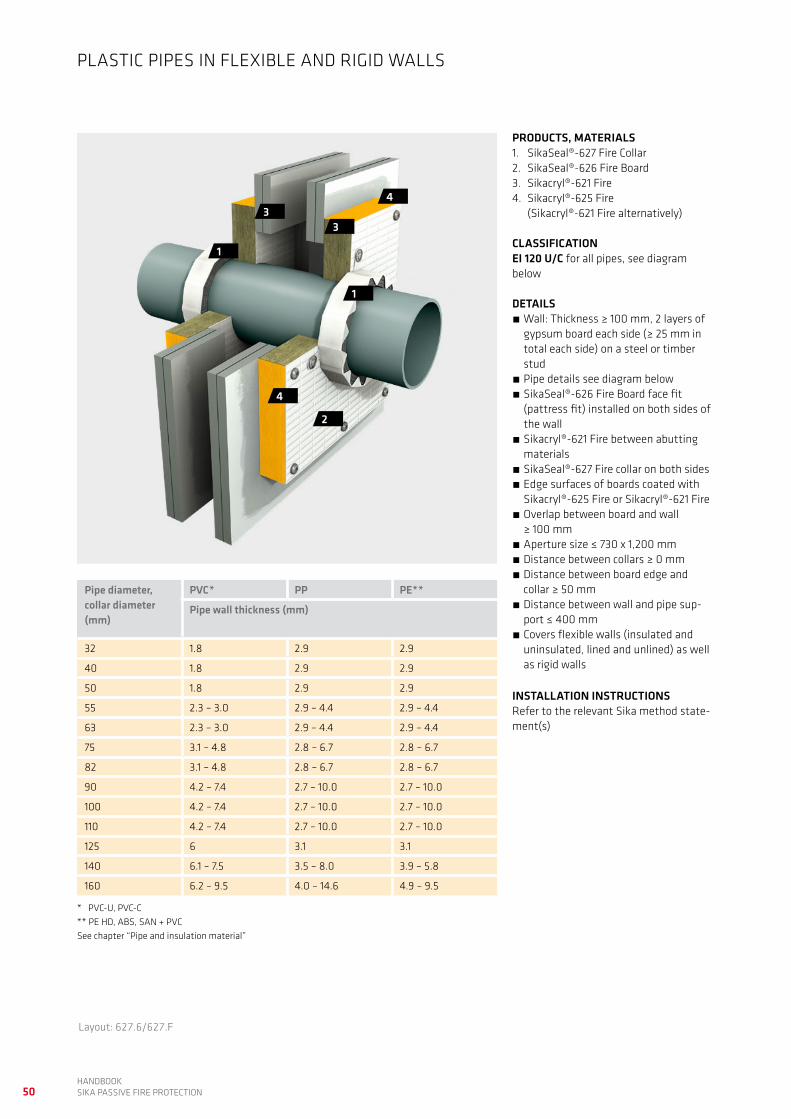
PRODUCTS, MATERIALS1. SikaSeal®-627 Fire Collar 2. SikaSeal®-626 Fire Board3. Sikacryl®-621 Fire
CLASSIFICATIONEI 120 U/C for all pipes, see diagram below
DETAILS Wall: Thickness ≥ 100 mm, ≥ 2 layers of gypsum board each side (≥ 25 mm in total each side) on a steel or timber stud
Pipe details see diagram below SikaSeal®-626 Fire Board internal fit, installed flush on both sides of the wall
Sikacryl®-621 Fire between abutting materials
SikaSeal®-627 Fire collar on both sides Aperture size ≤ 730 x 1,200 mm Distance between collars ≥ 0 mm Distance between aperture edge and collar ≥ 50 mm
Distance between wall and pipe sup-port ≤ 400 mm
Covers flexible walls (insulated, unlined and lined) as well as rigid walls
INSTALLATION INSTRUCTIONSRefer to the relevant Sika method state-ment(s)
PLASTIC PIPES IN FLEXIBLE AND RIGID WALLS
Pipe diameter, collar diameter (mm)
PVC* PP PE**
Pipe wall thickness (mm)
32 1.8 2.9 2.9
40 1.8 2.9 2.9
50 1.8 2.9 2.9
55 2.3 – 3.0 2.9 – 4.4 2.9 – 4.4
63 2.3 – 3.0 2.9 – 4.4 2.9 – 4.4
75 3.1 – 4.8 2.8 – 6.7 2.8 – 6.7
82 3.1 – 4.8 2.8 – 6.7 2.8 – 6.7
90 4.2 – 7.4 2.7 – 10.0 2.7 – 10.0
100 4.2 – 7.4 2.7 – 10.0 2.7 – 10.0
110 4.2 – 7.4 2.7 – 10.0 2.7 – 10.0
125 6 3.1 3.1
140 6.1 – 7.5 3.5 – 8.0 3.9 – 5.8
160 6.2 – 9.5 4.0 – 14.6 4.9 – 9.5
* PVC-U, PVC-C ** PE HD, ABS, SAN + PVC See chapter “Pipe and insulation material”
50HANDBOOK SIKA PASSIVE FIRE PROTECTION
2
33
1
1
4
4
Layout: 627.6/627.F
PRODUCTS, MATERIALS1. SikaSeal®-627 Fire Collar 2. SikaSeal®-626 Fire Board3. Sikacryl®-621 Fire4. Sikacryl®-625 Fire
(Sikacryl®-621 Fire alternatively)
CLASSIFICATIONEI 120 U/C for all pipes, see diagram below
DETAILS Wall: Thickness ≥ 100 mm, 2 layers of gypsum board each side (≥ 25 mm in total each side) on a steel or timber stud
Pipe details see diagram below SikaSeal®-626 Fire Board face fit (pattress fit) installed on both sides of the wall
Sikacryl®-621 Fire between abutting materials
SikaSeal®-627 Fire collar on both sides Edge surfaces of boards coated with Sikacryl®-625 Fire or Sikacryl®-621 Fire
Overlap between board and wall ≥ 100 mm
Aperture size ≤ 730 x 1,200 mm Distance between collars ≥ 0 mm Distance between board edge and collar ≥ 50 mm
Distance between wall and pipe sup-port ≤ 400 mm
Covers flexible walls (insulated and uninsulated, lined and unlined) as well as rigid walls
INSTALLATION INSTRUCTIONSRefer to the relevant Sika method state-ment(s)
PLASTIC PIPES IN FLEXIBLE AND RIGID WALLS
Pipe diameter, collar diameter (mm)
PVC* PP PE**
Pipe wall thickness (mm)
32 1.8 2.9 2.9
40 1.8 2.9 2.9
50 1.8 2.9 2.9
55 2.3 – 3.0 2.9 – 4.4 2.9 – 4.4
63 2.3 – 3.0 2.9 – 4.4 2.9 – 4.4
75 3.1 – 4.8 2.8 – 6.7 2.8 – 6.7
82 3.1 – 4.8 2.8 – 6.7 2.8 – 6.7
90 4.2 – 7.4 2.7 – 10.0 2.7 – 10.0
100 4.2 – 7.4 2.7 – 10.0 2.7 – 10.0
110 4.2 – 7.4 2.7 – 10.0 2.7 – 10.0
125 6 3.1 3.1
140 6.1 – 7.5 3.5 – 8.0 3.9 – 5.8
160 6.2 – 9.5 4.0 – 14.6 4.9 – 9.5
* PVC-U, PVC-C ** PE HD, ABS, SAN + PVC See chapter “Pipe and insulation material”

51HANDBOOK
SIKA PASSIVE FIRE PROTECTION
2
2
4
4
1
3
3
Pipe diameter (mm)
Annular space (mm)
Numbers of layers of SikaSeal®-629 Fire Wrap
32 – 50 4 1
50 – 82 6 2
82 – 115 8 3
115 – 160 10 4
160 – 200 12 5
200 – 250 14 6
PRODUCTS, MATERIALS1. SikaSeal®-626 Fire Board 2. Sikacryl®-621 Fire3. Sikacryl®-625 Fire
(Sikacryl®-621 Fire alternatively)4. SikaSeal®-628 Fire Wrap
(SikaSeal®-629 Fire Wrap alternatively)
CLASSIFICATIONEI 60 U/C
DETAILS Wall: Thickness ≥ 100 mm, ≥ 2 layers of gypsum board each side (≥ 25 mm in total each side) on a steel or timber stud
Pipe details see diagram below SikaSeal®-626 Fire Board face fit (pattress fit) installed on both sides of the wall
Edge surfaces of boards coated with Sikacryl®-625 Fire or Sikacryl®-621 Fire
Overlap between board and wall ≥ 100 mm
Annular space around pipes see table below
SikaSeal®-628 Fire Wrap according to pipe diameter on both sides; alternati-vely SikaSeal®-629 Fire Wrap according to table below on both sides
Sikacryl®-621 Fire 5 mm deep on both sides
Sikacryl®-621 Fire between board and wall
Aperture size ≤ 730 x 1,200 mm Distance between pipes (wrap) ≥ 0 mm Distance between aperture edge and pipes (wrap) ≥ 50 mm
Distance between wall and pipe sup-port ≤ 400 mm
Covers flexible walls (insulated and uninsulated, lined and unlined) as well as rigid walls
INSTALLATION INSTRUCTIONSRefer to the relevant Sika method state-ment(s)
PLASTIC PIPES IN FLEXIBLE AND RIGID WALLS
Layout: 626.13/626.I
Pipe diameter / pipe wall thickness diagram
Pipe
wal
l thi
ckne
ss (m
m)
50 70 90 110 130 150 170 190 200
2
4
6
8
0
10
12
14
16
18
20
Pipe diameter (mm)
6.9
18.4
18.2
11.9
9.6
7.7
4.94.6
3.72.9
1.8
PE PVC PP

52HANDBOOK SIKA PASSIVE FIRE PROTECTION
22
3
1
3
Layout: 626.14/626.J
PRODUCTS, MATERIALS1. SikaSeal®-626 Fire Board 2. Sikacryl®-621 Fire3. SikaSeal®-623 Fire
CLASSIFICATIONEI 90 U/C
DETAILS Wall: Thickness ≥ 150 mm, aerated concrete, concrete or brickwork, density ≥ 760 kg/m3
Pipe details see diagram below SikaSeal®-626 Fire Board internal fit, installed flush on both sides of the wall or centred in the middle of it
20 mm annular space around pipes se-aled with SikaSeal®-623 Fire, ≥ 25 mm deep on both sides
Sikacryl®-621 Fire between board and concrete
Aperture size ≤ 750 x 1,100 mm Distance between pipes (sealant) ≥ 50 mm
Distance between aperture edge and pipes (sealant) ≥ 50 mm
Distance between wall and pipe sup-port ≤ 400 mm
INSTALLATION INSTRUCTIONSRefer to the relevant Sika method state-ment(s)
PLASTIC PIPES IN RIGID WALLSPi
pe w
all t
hick
ness
(mm
)
Pipe diameter (mm)
30 50 70 90 110
2 2.4
4.8
7.47.4
4
6
8
013012520
Pipe diameter / pipe wall thickness diagram
PVC
53HANDBOOK
SIKA PASSIVE FIRE PROTECTION
Layout: 626.15/626.K
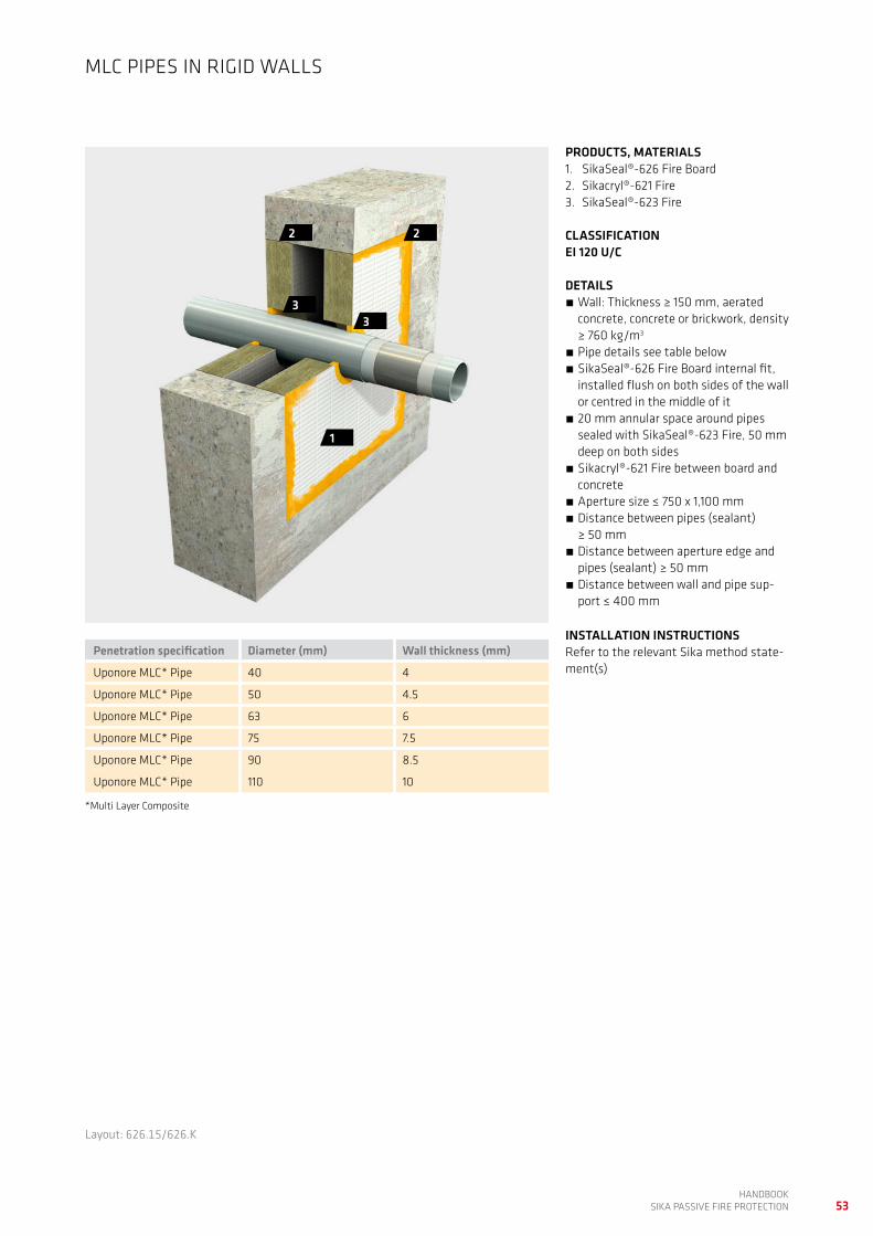
PRODUCTS, MATERIALS1. SikaSeal®-626 Fire Board 2. Sikacryl®-621 Fire3. SikaSeal®-623 Fire
CLASSIFICATIONEI 120 U/C
DETAILS Wall: Thickness ≥ 150 mm, aerated concrete, concrete or brickwork, density ≥ 760 kg/m3
Pipe details see table below SikaSeal®-626 Fire Board internal fit, installed flush on both sides of the wall or centred in the middle of it
20 mm annular space around pipes sealed with SikaSeal®-623 Fire, 50 mm deep on both sides
Sikacryl®-621 Fire between board and concrete
Aperture size ≤ 750 x 1,100 mm Distance between pipes (sealant) ≥ 50 mm
Distance between aperture edge and pipes (sealant) ≥ 50 mm
Distance between wall and pipe sup-port ≤ 400 mm
INSTALLATION INSTRUCTIONSRefer to the relevant Sika method state-ment(s)
MLC PIPES IN RIGID WALLS
22
33
1
Penetration specification Diameter (mm) Wall thickness (mm)
Uponore MLC* Pipe 40 4
Uponore MLC* Pipe 50 4.5
Uponore MLC* Pipe 63 6
Uponore MLC* Pipe 75 7.5
Uponore MLC* Pipe 90 8.5
Uponore MLC* Pipe 110 10
*Multi Layer Composite

54HANDBOOK SIKA PASSIVE FIRE PROTECTION
CABLES, CABLE TRAYS AND CONDUITS IN WALLS, LARGE APERTURES
Short description Products Code Page
Cables, cable trays and conduits in flexible and rigid wallsInsulated walls, lined aperturesInternal fit board installation
SikaSeal®-626 Fire BoardSikacryl®-621 Fire
626.9 55
Cables, cable trays and conduits in flexible and rigid wallsInsulated and uninsulated walls, lined and unlined aperturesFace fit (pattress fit) board installation
SikaSeal®-626 Fire BoardSikacryl®-621 FireSikacryl®-625 Fire (Sikacryl®-621 Fire alternatively)Insulation material
626.12 56
Cable trays in rigid wallsInternal fit board installation
SikaSeal®-623 FireSikaSeal®-626 Fire BoardSikacryl®-621 FireSikacryl®-625 Fire
623.4 57
Cables and conduits in flexible and rigid wallsInsulated walls, lined and unlined apertures
Sikacryl®-621 FireBacking material
621.3 58

55HANDBOOK
SIKA PASSIVE FIRE PROTECTION
22
2
1
Layout: 626.9/626.F
Penetration specification Classification
Electrical cables, diameter ≤ 21 mm EI 60
Electrical cables, diameter 22 – 80 mm EI 45, E 60
Cable trays and ladders EI 60
Cable bunches, diameter ≤ 100 mm, diameter of individual cables ≤ 21 mm
EI 60
Unsheathed electrical cables, diameter ≤ 17 mm EI 30, E 60
Unsheathed electrical cables, diameter 18 – 24 mm EI 15, E 60
Steel and copper conduits, diameter ≤ 16 mm EI 15, E 60
Plastic conduits, diameter ≤ 16 mm EI 60
PRODUCTS, MATERIALS1. SikaSeal®-626 Fire Board 2. Sikacryl®-621 Fire
CLASSIFICATIONSee table below
DETAILS Wall: Thickness ≥ 100 mm, ≥ 2 layers of gypsum board each side (≥ 25 mm in total each side) on a steel or timber stud
Cables/conduits details see table below
Covers perforated and unperforated cable trays as well as leathers, width ≤ 500 mm
SikaSeal®-626 Fire Board internal fit, installed flush on both sides of the wall
Sikacryl®-621 Fire between abutting materials
Aperture size ≤ 730 x 1,200 mm Distance between cables/cable trays/conduits ≥ 50 mm
Distance between aperture edge and cables/cable trays/conduits ≥ 50 mm
Distance between wall and cable, cable tray support ≤ 250 mm
Covers flexible walls (insulated, lined) as well as rigid walls
INSTALLATION INSTRUCTIONSRefer to the relevant Sika method state-ment(s)
CABLES, CABLE TRAYS AND CONDUITS IN FLEXIBLE AND RIGID WALLS

56HANDBOOK SIKA PASSIVE FIRE PROTECTION
PRODUCTS, MATERIALS1. SikaSeal®-626 Fire Board 2. Sikacryl®-621 Fire3. Sikacryl®-625 Fire
(Sikacryl®-621 Fire alternatively)4. Insulation material
CLASSIFICATIONEI 120
DETAILS Wall: Thickness ≥ 100 mm, ≥ 2 layers of gypsum board each side (≥ 25 mm in total each side) on a steel or timber stud
Cables/conduits details see table below
Insulation: Stone wool or ceramic wool, density ≥ 45 kg/m3, thickness ≥ 40 mm, length ≥ 300 mm, both sides, LI (local interrupted)
SikaSeal®-626 Fire Board face fit (pattress fit) installed on both sides of the wall
Edge surfaces of boards coated with Sikacryl®-625 Fire or Sikacryl®-621 Fire
Overlap between board and wall ≥ 100 mm
Sikacryl®-621 Fire between abutting materials
Aperture size ≤ 730 x 1,200 mm Distance between cables/cable trays/conduits (insulation) ≥ 50 mm
Distance between aperture edge and cables/cable trays/conduits (insulati-on) ≥ 50 mm
Distance between wall and cable, cable tray support ≤ 400 mm
Covers flexible walls (insulated and uninsulated, lined and unlined) as well as rigid walls
INSTALLATION INSTRUCTIONSRefer to the relevant Sika method state-ment(s)
CABLES, CABLE TRAYS AND CONDUITS IN FLEXIBLE AND RIGID WALLS
2
1
4
3
3
Penetration specification
Electrical cables, diameter ≤ 80 mm
Cable trays and ladders (perforated and unperforated, width ≤ 500 mm) loaded with the following cables
Cable bunches, diameter ≤ 100 mm, diameter of individual cables ≤ 21 mm
Unsheathed electrical cables, diameter ≤ 24 mm
Steel and copper conduits, diameter ≤ 16 mm
Plastic conduits, diameter ≤ 16 mm
Layout: 626.12/626.H

57HANDBOOK
SIKA PASSIVE FIRE PROTECTION
PRODUCTS, MATERIALS1. SikaSeal®-623 Fire 2. SikaSeal®-626 Fire Board3. Sikacryl®-621 Fire4. Sikacryl®-625 Fire
CLASSIFICATIONSee table below
DETAILS Wall: Thickness ≥ 150 mm, aerated concrete, concrete or brickwork, density ≥ 760 kg/m3
SikaSeal®-626 Fire Board internal fit, installed flush on both sides of the wall or centred in the middle of it
Cables, cable tray details see table below
Coating: Cables and cable trays coated with Sikacryl®-625 Fire on both sides of the wall. Length ≥ 300 mm, DFT (dry film thickness) ≥ 2 mm
20 mm space on top of cables sealed with SikaSeal®-623 Fire, 25 mm deep on both sides
Sikacryl®-621 Fire between abutting materials
Aperture size ≤ 750 x 1,100 mm Distance between cable trays ≥ 100 mm
Distance between aperture edge and cable trays ≥ 50 mm
Distance between wall and cable tray support ≤ 200 mm
INSTALLATION INSTRUCTIONSRefer to the relevant Sika method state-ment(s)
CABLE TRAYS IN RIGID WALLS
2
1 4
33
Penetration specification Classification
Cable trays and ladders (perforated and unperforated, width ≤ 500 mm) loaded with the following cables
EI 120
Electrical cables, diameter ≤ 21 mm EI 120
“C1 cable” acc. EN 1366-3 EI 120
“C2 cable” acc. EN 1366-3 EI 90, E 120
“C3 cable” acc. EN 1366-3 EI 120
Layout: 623.4/623.C
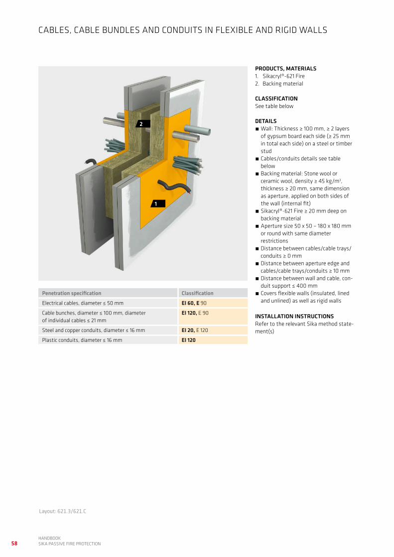
58HANDBOOK SIKA PASSIVE FIRE PROTECTION
PRODUCTS, MATERIALS1. Sikacryl®-621 Fire 2. Backing material
CLASSIFICATIONSee table below
DETAILS Wall: Thickness ≥ 100 mm, ≥ 2 layers of gypsum board each side (≥ 25 mm in total each side) on a steel or timber stud
Cables/conduits details see table below
Backing material: Stone wool or ceramic wool, density ≥ 45 kg/m3, thickness ≥ 20 mm, same dimension as aperture, applied on both sides of the wall (internal fit)
Sikacryl®-621 Fire ≥ 20 mm deep on backing material
Aperture size 50 x 50 – 180 x 180 mm or round with same diameter restrictions
Distance between cables/cable trays/conduits ≥ 0 mm
Distance between aperture edge and cables/cable trays/conduits ≥ 10 mm
Distance between wall and cable, con-duit support ≤ 400 mm
Covers flexible walls (insulated, lined and unlined) as well as rigid walls
INSTALLATION INSTRUCTIONSRefer to the relevant Sika method state-ment(s)
CABLES, CABLE BUNDLES AND CONDUITS IN FLEXIBLE AND RIGID WALLS
2
1
Penetration specification Classification
Electrical cables, diameter ≤ 50 mm EI 60, E 90
Cable bunches, diameter ≤ 100 mm, diameter of individual cables ≤ 21 mm
EI 120, E 90
Steel and copper conduits, diameter ≤ 16 mm EI 20, E 120
Plastic conduits, diameter ≤ 16 mm EI 120
Layout: 621.3/621.C

59HANDBOOK
SIKA PASSIVE FIRE PROTECTION

60HANDBOOK SIKA PASSIVE FIRE PROTECTION
Short description Products Code Page
Insulated steel and copper pipes in flexible and rigid wallsArmaflex AF foam pipe insulationInsulated walls, lined and unlined apertures
SikaSeal®-623 Fire 623.1 61
Insulated steel and copper pipes in flexible and rigid wallsArmaflex AF foam pipe insulationInsulated walls, lined and unlined apertures
SikaSeal®-623 Fire 623.2 62
INSULATED METAL PIPES IN WALLS, SMALL APERTURES

61HANDBOOK
SIKA PASSIVE FIRE PROTECTION
PRODUCTS, MATERIALS1. SikaSeal®-623 Fire
CLASSIFICATIONSee table below
DETAILS Wall: Thickness ≥ 120 mm, ≥ 2 layers of gypsum board each side (≥ 25 mm in total each side) on a steel or timber stud
Pipes: Steel and copper or metals with higher melting point and/or lower thermal conductivity, details see table below
Pipe insulation: Armaflex AF foam insulation, CS (continuous sustained)
Core drilled holes, 20 mm annular space around pipes
Sikacryl®-623 Fire ≥ 25 mm deep on both sides
Distance between pipes (sealant) ≥ 100 mm
Covers flexible walls (insulated, lined and unlined) as well as rigid walls
Distance between wall and pipe sup-port ≤ 150 mm
INSTALLATION INSTRUCTIONSRefer to the relevant Sika method state-ment(s)
INSULATED METAL PIPES IN FLEXIBLE AND RIGID WALLS
11
Pipe diameter (mm)
Pipe wall thickness (mm)
Pipe insulationthickness (mm)
Classification
60 0.8 – 14.2 32 EI 90 C/U
15 0.8 – 7.0 13 EI 120 C/U
Layout: 623.1/623.A

62HANDBOOK SIKA PASSIVE FIRE PROTECTION
11
Layout: 623.2/623.A
PRODUCTS, MATERIALS1. SikaSeal®-623 Fire
CLASSIFICATIONSee table below
DETAILS Wall: Thickness ≥ 100 mm, ≥ 2 layers of gypsum board each side (≥ 25 mm in total each side) on a steel or timber stud
Pipes: Steel and copper or metals with higher melting point and/or lower thermal conductivity, details see table below
Pipe insulation: Armaflex AF foam insulation, CS (continuous sustained)
Core drilled holes, 20 mm annular space around pipes
Sikacryl®-623 Fire ≥ 25 mm deep on both sides
Distance between pipes (sealant) ≥ 100 mm
Covers flexible walls (insulated, lined and unlined) as well as rigid walls
Distance between wall and pipe sup-port ≤ 150 mm
INSTALLATION INSTRUCTIONSRefer to the relevant Sika method state-ment(s)
INSULATED METAL PIPES IN FLEXIBLE AND RIGID WALLS
Pipe diameter (mm)
Pipe wall thickness (mm)
Pipe insulationthickness (mm)
Classification
40 1.5 – 14.2 32 EI 30, E 120 C/U
40 – 159 2.0 – 14.2 32 EI 30, E 120 C/U

63HANDBOOK
SIKA PASSIVE FIRE PROTECTION

64HANDBOOK SIKA PASSIVE FIRE PROTECTION
UNINSULATED METAL PIPES IN WALLS, SMALL APERTURES
Short description Products Code Page
Uninsulated steel pipes in flexible and rigid wallsInsulated walls, lined and unlined apertures
Sikacryl®-621 Fire 621.1 65
Uninsulated steel and copper pipes in flexible and rigid wallsInsulated walls, lined and unlined apertures
Sikacryl®-621 FirePipe insulation
621.2 66
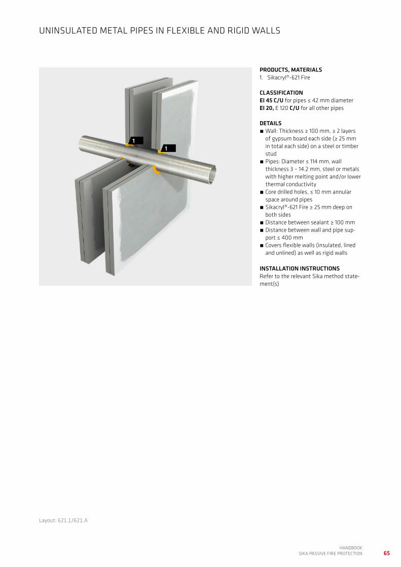
65HANDBOOK
SIKA PASSIVE FIRE PROTECTION
PRODUCTS, MATERIALS1. Sikacryl®-621 Fire
CLASSIFICATIONEI 45 C/U for pipes ≤ 42 mm diameterEI 20, E 120 C/U for all other pipes
DETAILS Wall: Thickness ≥ 100 mm, ≥ 2 layers of gypsum board each side (≥ 25 mm in total each side) on a steel or timber stud
Pipes: Diameter ≤ 114 mm, wall thickness 3 – 14.2 mm, steel or metals with higher melting point and/or lower thermal conductivity
Core drilled holes, ≤ 10 mm annular space around pipes
Sikacryl®-621 Fire ≥ 25 mm deep on both sides
Distance between sealant ≥ 100 mm Distance between wall and pipe sup-port ≤ 400 mm
Covers flexible walls (insulated, lined and unlined) as well as rigid walls
INSTALLATION INSTRUCTIONSRefer to the relevant Sika method state-ment(s)
UNINSULATED METAL PIPES IN FLEXIBLE AND RIGID WALLS
11
Layout: 621.1/621.A

66HANDBOOK SIKA PASSIVE FIRE PROTECTION
PRODUCTS, MATERIALS1. Sikacryl®-621 Fire 2. Pipe insulation
CLASSIFICATIONEI 90 C/U for pipes ≤ 40 mm diameterEI 20, E 120 C/U for all other pipes
DETAILS Wall: Thickness ≥ 120 mm, ≥ 2 layers of gypsum board each side (≥ 25 mm in total each side) on a steel or timber stud
Pipes: Diameter ≤ 159 mm, wall thick-ness 1.8 – 14.2 mm, steel and copper or metals with higher melting point and/or lower thermal conductivity
Pipe insulation: ceramic wool, density ≥ 160 kg/m3, thickness ≥ 6 mm, length ≥ 300 mm, both sides of the wall, LI (local interrupted)
Core drilled holes, ≤ 10 mm annular space around pipes
Sikacryl®-621 Fire ≥ 25 mm deep on both sides
Distance between insulation ≥ 100 mm Distance between wall and pipe sup-port ≤ 150 mm
Covers flexible walls (insulated, lined and unlined) as well as rigid walls
INSTALLATION INSTRUCTIONSRefer to the relevant Sika method state-ment(s)
UNINSULATED METAL PIPES IN FLEXIBLE AND RIGID WALLS
2
11
Layout: 621.2/621.B

67HANDBOOK
SIKA PASSIVE FIRE PROTECTION

68HANDBOOK SIKA PASSIVE FIRE PROTECTION
PLASTIC AND MLC PIPES IN WALLS, SMALL APERTURES
Short description Products Code Page
Plastic pipes in flexible and rigid wallsPipes U/CInsulated and uninsulated walls, lined and unlined apertures
SikaSeal®-627 Fire CollarSikacryl®-621 Fire
627.4 69
Plastic pipes in flexible and rigid wallsPipes U/UInsulated and uninsulated walls, lined and unlined apertures
SikaSeal®-627 Fire CollarSikacryl®-621 Fire
627.8 70
Angled plastic pipes in flexible and rigid wallsInsulated and uninsulated walls, lined and unlined apertures
SikaSeal®-627 Fire CollarSikacryl®-621 Fire
627.9 71
Plastic pipes in flexible and rigid wallsInsulated walls, lined and unlined apertures
SikaSeal®-623 Fire 623.3 72
Plastic pipes in flexible and rigid wallsInsulated walls, lined and unlined apertures
SikaSeal®-628 Fire Wrap (SikaSeal®-629 Fire Wrap alternatively)Sikacryl®-621 Fire
628.2 73
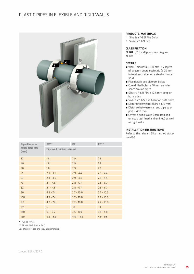
69HANDBOOK
SIKA PASSIVE FIRE PROTECTION
PRODUCTS, MATERIALS1. SikaSeal®-627 Fire Collar 2. Sikacryl®-621 Fire
CLASSIFICATIONEI 120 U/C for all pipes, see diagram below
DETAILS Wall: Thickness ≥ 100 mm, ≥ 2 layers of gypsum board each side (≥ 25 mm in total each side) on a steel or timber stud
Pipe details see diagram below Core drilled holes, ≤ 10 mm annular space around pipes
Sikacryl®-621 Fire ≥ 12.5 mm deep on both sides
SikaSeal®-627 Fire Collar on both sides Distance between collars ≥ 100 mm Distance between wall and pipe sup-port ≤ 400 mm
Covers flexible walls (insulated and uninsulated, lined and unlined) as well as rigid walls
INSTALLATION INSTRUCTIONSRefer to the relevant Sika method state-ment(s)
PLASTIC PIPES IN FLEXIBLE AND RIGID WALLS
2
1
1
Layout: 627.4/627.D
Pipe diameter, collar diameter (mm)
PVC* PP PE**
Pipe wall thickness (mm)
32 1.8 2.9 2.9
40 1.8 2.9 2.9
50 1.8 2.9 2.9
55 2.3 – 3.0 2.9 – 4.4 2.9 – 4.4
63 2.3 – 3.0 2.9 – 4.4 2.9 – 4.4
75 3.1 – 4.8 2.8 – 6.7 2.8 – 6.7
82 3.1 – 4.8 2.8 – 6.7 2.8 – 6.7
90 4.2 – 7.4 2.7 – 10.0 2.7 – 10.0
100 4.2 – 7.4 2.7 – 10.0 2.7 – 10.0
110 4.2 – 7.4 2.7 – 10.0 2.7 – 10.0
125 6 3.1 3.1
140 6.1 – 7.5 3.5 – 8.0 3.9 – 5.8
160 6.2 – 9.5 4.0 – 14.6 4.9 – 9.5
* PVC-U, PVC-C ** PE HD, ABS, SAN + PVC See chapter “Pipe and insulation material”

70HANDBOOK SIKA PASSIVE FIRE PROTECTION
PRODUCTS, MATERIALS1. SikaSeal®-627 Fire Collar 2. Sikacryl®-621 Fire
CLASSIFICATIONEI 60 U/U for all pipes, see diagram below
DETAILS Wall: Thickness ≥ 100 mm, ≥ 2 layers of gypsum board each side (≥ 25 mm in total each side) on a steel or timber stud
Pipe details see diagram below Core drilled holes, ≤ 10 mm annular space around pipes
Sikacryl®-621 Fire ≥ 12.5 mm deep on both sides
SikaSeal®-627 Fire Collar on both sides Distance between collars ≥ 100 mm Distance between wall and pipe sup-port ≤ 400 mm
Covers flexible walls (insulated and uninsulated, lined and unlined) as well as rigid walls
INSTALLATION INSTRUCTIONSRefer to the relevant Sika method state-ment(s)
PLASTIC PIPES IN FLEXIBLE AND RIGID WALLS
2
1
1
Layout: 627.8/627.D
Pipe diameter, collar diameter (mm)
PVC* PP PE**
Pipe wall thickness (mm)
32 1.8 – 3.7 2.0 – 6.9 3.1 – 4.6
40 1.8 – 3.7 2.0 – 6.9 3.1 – 4.6
50 1.8 – 3.7 2.0 – 6.9 3.1 – 4.6
55 2.2 – 4.3 2.1 – 7.5 3.0 – 5.7
63 2.2 – 4.3 2.1 – 7.5 3.0 – 5.7
75 3.2 – 5.2 2.3 – 8.5 2.9 – 7.4
82 3.2 – 5.2 2.3 – 8.5 2.9 – 7.4
90 4.2 – 6.6 2.7 – 10.0 2.7 – 10.0
100 4.2 – 6.6 2.7 – 10.0 2.7 – 10.0
110 4.2 – 6.6 2.7 – 10.0 2.7 – 10.0
125 4.8 – 7.4 3.1 – 17.1 3.1 – 11.4
140 5.4 – 8.3 3.5 – 11.5 3.4 – 10.5
160 6.2 – 9.5 4.0 – 14.6 4.0 – 9.5
* PVC-U, PVC-C ** PE HD, ABS, SAN + PVC See chapter “Pipe and insulation material”

71HANDBOOK
SIKA PASSIVE FIRE PROTECTION
Layout: 627.9/627.H
PRODUCTS, MATERIALS1. SikaSeal®-627 Fire Collar 2. Sikacryl®-621 Fire
CLASSIFICATIONEI 90 U/C for all pipes, see diagram below
DETAILS Wall: Thickness ≥ 100 mm, ≥ 2 layers of gypsum board each side (≥ 25 mm in total each side) on a steel or timber stud
Pipe details see diagram below Core drilled holes, ≤ 10 mm annular space around pipes
Sikacryl®-621 Fire ≥ 12.5 mm deep on both sides
SikaSeal®-627 Fire Collar on both sides for collar sizes see table below.
Distance between collars ≥ 0 mm Distance between wall and pipe sup-port ≤ 400 mm
Pipes installed at a horizontal or verti-cal angle of 90 – 30° in relation to the wall surface. Pipe details see diagram below
Covers flexible walls (insulated and uninsulated, lined and unlined) as well as rigid walls
INSTALLATION INSTRUCTIONSRefer to the relevant Sika method state-ment(s)
ANGLED PLASTIC PIPES IN FLEXIBLE AND RIGID WALLS
2
2
1
Pipe diameter, collar diameter (mm)
PVC* PP PE**
Pipe wall thickness (mm)
32 1.8 2.9 2.9
40 1.8 2.9 2.9
50 1.8 2.9 2.9
55 2.3 – 3.0 2.9 – 4.4 2.9 – 4.4
63 2.3 – 3.0 2.9 – 4.4 2.9 – 4.4
75 3.1 – 4.8 2.8 – 6.7 2.8 – 6.7
82 3.1 – 4.8 2.8 – 6.7 2.8 – 6.7
90 4.2 – 7.4 2.7 – 10.0 2.7 – 10.0
100 4.2 – 7.4 2.7 – 10.0 2.7 – 10.0
110 4.2 – 7.4 2.7 – 10.0 2.7 – 10.0
125 6 3.1 3.1
140 6.1 – 7.5 3.5 – 8.0 3.9 – 5.8
160 6.2 – 9.5 4.0 – 14.6 4.9 – 9.5
* PVC-U, PVC-C ** PE HD, ABS, SAN + PVC See chapter “Pipe and insulation material”
Pipe diameter (mm)
Pipe angle in relation to wall
75° 60° 45°
Required collar diameter (mm)
32 55 63 82
40 55 75 90
50 63 82 110
55 75 82 110
63 75 110 125
75 90 110 160
82 110 125 160
90 110 125 200
100 125 140 200
110 125 160 200
125 160 200 –
140 160 – –
160 200 – –
For pipes installed at angles different to 90° (perpendicular to wall) larger collars are required. The above tables gives an overview to typical angles. For other angles please contakt Sika Technical Service.

72HANDBOOK SIKA PASSIVE FIRE PROTECTION
PRODUCTS, MATERIALS1. SikaSeal®-623 Fire
CLASSIFICATIONSee table below
DETAILS Wall: Thickness ≥ 100 mm, ≥ 2 layers of gypsum board each side (≥ 25 mm in total each side) on a steel or timber stud
Pipes details see table below Core drilled holes, 20 mm annular space around pipes
Sikacryl®-623 Fire ≥ 25 mm deep on both sides with a 10 mm fillet on the outer face
Distance between pipes (sealant) ≥ 100 mm
Distance between wall and pipe sup-port ≤ 260 mm
Covers flexible walls (insulated, lined and unlined) as well as rigid walls
INSTALLATION INSTRUCTIONSRefer to the relevant Sika method state-ment(s)
PLASTIC PIPES IN FLEXIBLE AND RIGID WALLS
1
1
Layout: 623.3/623.B
Pipe material Pipe diameter Pipe wallthickness (mm)
Classification
PVC 40 1.9 EI 120 C/U
PVC 125 9.2 EI 60 C/U
ABS 40 1.9 EI 120 C/U
PP 40 2.0 EI 120 C/U

73HANDBOOK
SIKA PASSIVE FIRE PROTECTION
PRODUCTS, MATERIALS1. SikaSeal®-628 Fire Wrap
(SikaSeal®-629 Fire Wrap alternatively)2. Sikacryl®-621 Fire
CLASSIFICATIONPVC: EI 120 U/CPP, PE: EI 90 U/CDetails see diagram below
DETAILS Wall: Thickness ≥ 120 mm, ≥ 2 layers of gypsum board each side (≥ 25 mm in to-tal each side) on a steel or timber stud
Pipe details see diagram below Core drilled holes, annular space around pipes see table below
SikaSeal®-628 Fire Wrap according to pipe diameter on both sides; alternati-vely SikaSeal®-629 Fire Wrap according to table below on both sides
Sikacryl®-621 Fire 5 mm deep on both sides
Distance between pipes (wrap) ≥ 100 mm
Distance between wall and pipe support ≤ 400 mm
Covers flexible walls (insulated, lined and unlined) as well as rigid walls
INSTALLATION INSTRUCTIONSRefer to the relevant Sika method state-ment(s)
PLASTIC PIPES IN FLEXIBLE AND RIGID WALLS
21
Layout: 628.2/628.B
Pipe diameter (mm)
Annular space Numbers of layers of SikaSeal®-629 Fire Wrap
32 – 50 4 1
50 – 82 6 2
82 – 115 8 3
115 – 160 10 4
160 – 200 12 5
200 – 250 14 6
Pipe diameter / pipe wall thickness diagram
Pipe
wal
l thi
ckne
ss (m
m)
20
2
4
6
8
0
10
12
14
16
18
50 70 90 110 130 150 170 190 200
Pipe diameter (mm)
1.8
2.9
9.6
18.418.2 18.2
11.9
4.9
9.6
7.7
PE PVC PP

74HANDBOOK SIKA PASSIVE FIRE PROTECTION
Short description Products Code Page
Cables and conduits in flexible and rigid walls Sikacryl®-621 Fire 621.4 75
Insulated walls, lined and unlined apertures
CABLES, CABLE TRAYS AND CONDUITS IN WALLS, SMALL APERTURES

75HANDBOOK
SIKA PASSIVE FIRE PROTECTION
PRODUCTS, MATERIALS1. Sikacryl®-621 Fire 2. Backing material
CLASSIFICATIONSee table below
DETAILS Wall: Thickness ≥ 75 mm, ≥ 1 layers of gypsum board each side (≥ 12.5 mm in total each side) on a steel or timber stud
Core drilled holes ≤ 25 mm diameter Sikacryl®-621 Fire ≥ 12 mm deep on both sides backed with ≥ 10 mm stone-wool, density ≥ 45 kg/m3
Cable and conduit detail see table below
Distance between aperture edge and cables ≥ 0 mm
Distance between wall and cable sup-port ≤ 980 mm
Covers flexible walls (insulated, lined and unlined) as well as rigid walls
INSTALLATION INSTRUCTIONSRefer to the relevant Sika method state-ment(s)
CABLES AND CONDUITS IN FLEXIBLE AND RIGID WALLS
21
Penetration specification Classification
Electrical cables, diameter 18 – 21 mm EI 60, E 90
Copper conduits, diameter ≤ 15 mm, pipe wall thickness 0.7 mm
EI 60, E 90
Stainless steel conduits, diameter ≤ 15 mm, pipe wall thickness 1.0 mm
EI 90
Layout: 621.4/621.D

76HANDBOOK SIKA PASSIVE FIRE PROTECTION
UNINSULATED METAL PIPES IN FLOORS, LARGE APERTURES
Short description Products Code Page
Uninsulated metal pipes in rigid floors, non-load-bearingInternal fit board installation
SikaSeal®-626 Fire BoardSikacryl®-621 FirePipe insulation
626.16 77
Uninsulated metal pipes in rigid floors, load-bearing Sikacrete®-630 Fire 630.2 78
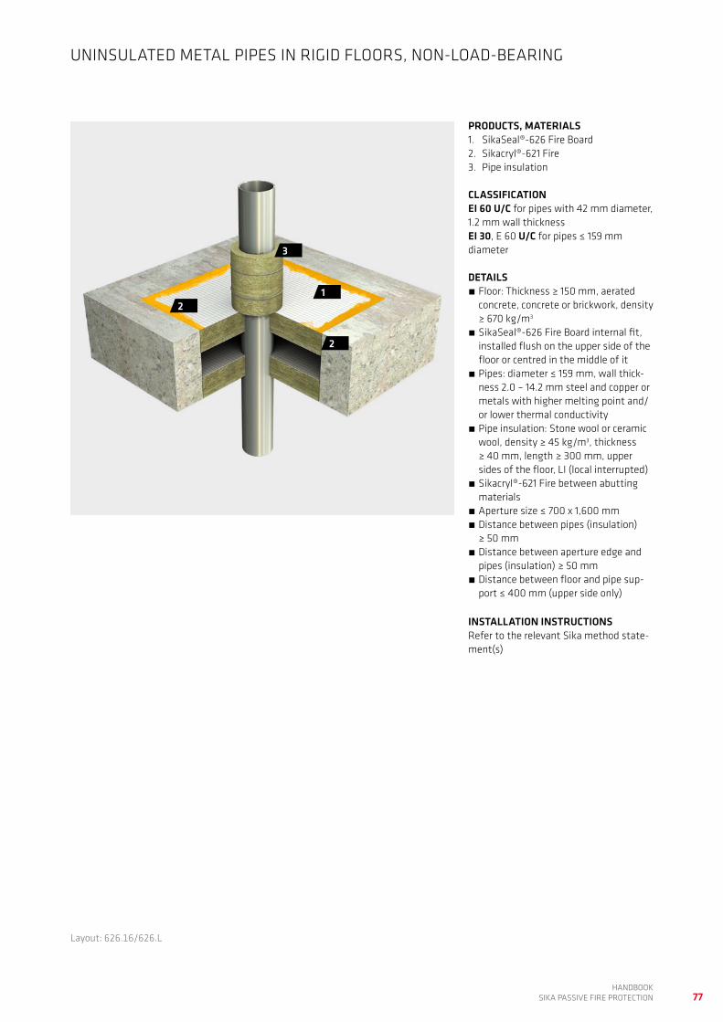
77HANDBOOK
SIKA PASSIVE FIRE PROTECTION
PRODUCTS, MATERIALS1. SikaSeal®-626 Fire Board 2. Sikacryl®-621 Fire3. Pipe insulation
CLASSIFICATIONEI 60 U/C for pipes with 42 mm diameter, 1.2 mm wall thicknessEI 30, E 60 U/C for pipes ≤ 159 mm diameter
DETAILS Floor: Thickness ≥ 150 mm, aerated concrete, concrete or brickwork, density ≥ 670 kg/m3
SikaSeal®-626 Fire Board internal fit, installed flush on the upper side of the floor or centred in the middle of it
Pipes: diameter ≤ 159 mm, wall thick-ness 2.0 – 14.2 mm steel and copper or metals with higher melting point and/or lower thermal conductivity
Pipe insulation: Stone wool or ceramic wool, density ≥ 45 kg/m3, thickness ≥ 40 mm, length ≥ 300 mm, upper sides of the floor, LI (local interrupted)
Sikacryl®-621 Fire between abutting materials
Aperture size ≤ 700 x 1,600 mm Distance between pipes (insulation) ≥ 50 mm
Distance between aperture edge and pipes (insulation) ≥ 50 mm
Distance between floor and pipe sup-port ≤ 400 mm (upper side only)
INSTALLATION INSTRUCTIONSRefer to the relevant Sika method state-ment(s)
UNINSULATED METAL PIPES IN RIGID FLOORS, NON-LOAD-BEARING
2
2
1
3
Layout: 626.16/626.L

78HANDBOOK SIKA PASSIVE FIRE PROTECTION
PRODUCTS, MATERIALS1. Sikacrete®-630 Fire2. Insulation material
CLASSIFICATIONSee table below
DETAILS Floor: Thickness ≥ 150 mm, aerated concrete, concrete or brickwork, density ≥ 670 kg/m3
Pipe details see table below Insulation: Stone wool or ceramic wool, density ≥ 150 kg/m3, thickness ≥ 50 mm, length ≥ 500 mm on the upper side of the floor, LI (locally interrupted)
Sikacrete®-630 Fire: ≥ 100 mm thick, flush on the upper side of the floor
Aperture size ≤ 1,800 x 1,800 mm Sikacrete®-630 Fire: ≥ 100 mm thick, flush on upper side of the floor
Distance between cable, pipes ≥ 100 mm
Distance between aperture edge and cable trays ≥ 100 mm
Distance between floor and pipe sup-port ≤ 150 mm (upper side only)
INSTALLATION INSTRUCTIONSRefer to the relevant Sika method state-ment(s)
UNINSULATED METAL PIPES IN RIGID FLOORS, LOAD-BEARING
2
1
Pipe specification Classification
Copper pipes, diameter 40 – 107 mm, wall thickness 1.5 – 14.2 mm EI 15, E 60 C/U
Steel pipes, diameter 40 – 115 mm, wall thickness 3.0 – 14.2 mm EI 120 C/U
Steel pipes, diameter 40 – 160 mm, wall thickness 3.0 – 14.2 mm EI 90 C/U
Layout: 630.2/630.B

79HANDBOOK
SIKA PASSIVE FIRE PROTECTION

80HANDBOOK SIKA PASSIVE FIRE PROTECTION
PLASTIC AND MLC PIPES IN FLOORS, LARGE APERTURES
Short description Products Code Page
Plastic pipes in rigid floors, load-bearing SikaSeal®-627 Fire CollarSikacrete®-630 Fire
627.2 81
Plastic pipes in rigid floors, non-load-bearingInternal fit board installation
SikaSeal®-626 Fire BoardSikacryl®-621 FireSikaSeal®-627 Fire Collar
627.3 82
Plastic pipes in rigid floors, non-load-bearingInternal fit board installation
SikaSeal®-626 Fire BoardSikaSeal®-623 Fire Sikacryl®-621 Fire
626.18 83
MLC pipes in rigid floors, non-load-bearingInternal fit board installation
SikaSeal®-626 Fire BoardSikaSeal®-623 Fire Sikacryl®-621 Fire
626.19 84

81HANDBOOK
SIKA PASSIVE FIRE PROTECTION
PRODUCTS, MATERIALS1. SikaSeal®-627 Fire Collar 2. Sikacrete®-630 Fire
CLASSIFICATIONEI 120 U/C for all pipes, see diagram below
DETAILS Floor: Thickness ≥ 150 mm, aerated concrete, concrete or brickwork, density ≥ 670 kg/m3
Pipe details see diagram below Sikacrete®-630 Fire: ≥ 100 mm thick, flush on upper side of the floor
SikaSeal®-627 Fire Collar on the lower side of the floor
Aperture size ≤ 700 x 1,400 mm Distance between collars ≥ 0 mm Distance between aperture edge and collar ≥ 50 mm
Distance between floor and pipe sup-port ≤ 400 mm (upper side only)
INSTALLATION INSTRUCTIONSRefer to the relevant Sika method state-ment(s)
PLASTIC PIPES IN RIGID FLOORS, LOAD-BEARING
2
1
Layout: 627.2/627.B
Pipe diameter, collar diameter (mm)
PVC* PP PE**
Pipe wall thickness (mm)
32 1.8 2.9 2.9
40 1.8 2.9 2.9
50 1.8 2.9 2.9
55 2.3 – 3.0 2.9 – 4.4 2.9 – 4.4
63 2.3 – 3.0 2.9 – 4.4 2.9 – 4.4
75 3.1 – 4.8 2.8 – 6.7 2.8 – 6.7
82 3.1 – 4.8 2.8 – 6.7 2.8 – 6.7
90 4.2 – 7.4 2.7 – 10.0 2.7 – 10.0
100 4.2 – 7.4 2.7 – 10.0 2.7 – 10.0
110 4.2 – 7.4 2.7 – 10.0 2.7 – 10.0
125 6 3.1 3.1
140 6.1 – 7.5 3.5 – 8.0 3.9 – 5.8
160 6.2 – 9.5 4.0 – 14.6 4.9 – 9.5
* PVC-U, PVC-C ** PE HD, ABS, SAN + PVC See chapter “Pipe and insulation material”
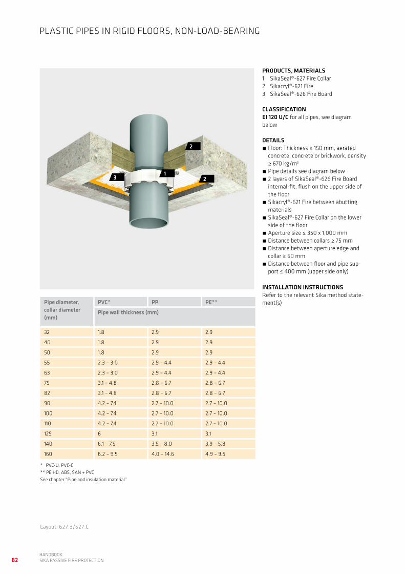
82HANDBOOK SIKA PASSIVE FIRE PROTECTION
2
2
3 1
PRODUCTS, MATERIALS1. SikaSeal®-627 Fire Collar 2. Sikacryl®-621 Fire3. SikaSeal®-626 Fire Board
CLASSIFICATIONEI 120 U/C for all pipes, see diagram below
DETAILS Floor: Thickness ≥ 150 mm, aerated concrete, concrete or brickwork, density ≥ 670 kg/m3
Pipe details see diagram below 2 layers of SikaSeal®-626 Fire Board internal-fit, flush on the upper side of the floor
Sikacryl®-621 Fire between abutting materials
SikaSeal®-627 Fire Collar on the lower side of the floor
Aperture size ≤ 350 x 1,000 mm Distance between collars ≥ 75 mm Distance between aperture edge and collar ≥ 60 mm
Distance between floor and pipe sup-port ≤ 400 mm (upper side only)
INSTALLATION INSTRUCTIONSRefer to the relevant Sika method state-ment(s)
Layout: 627.3/627.C
PLASTIC PIPES IN RIGID FLOORS, NON-LOAD-BEARING
Pipe diameter, collar diameter (mm)
PVC* PP PE**
Pipe wall thickness (mm)
32 1.8 2.9 2.9
40 1.8 2.9 2.9
50 1.8 2.9 2.9
55 2.3 – 3.0 2.9 – 4.4 2.9 – 4.4
63 2.3 – 3.0 2.9 – 4.4 2.9 – 4.4
75 3.1 – 4.8 2.8 – 6.7 2.8 – 6.7
82 3.1 – 4.8 2.8 – 6.7 2.8 – 6.7
90 4.2 – 7.4 2.7 – 10.0 2.7 – 10.0
100 4.2 – 7.4 2.7 – 10.0 2.7 – 10.0
110 4.2 – 7.4 2.7 – 10.0 2.7 – 10.0
125 6 3.1 3.1
140 6.1 – 7.5 3.5 – 8.0 3.9 – 5.8
160 6.2 – 9.5 4.0 – 14.6 4.9 – 9.5
* PVC-U, PVC-C ** PE HD, ABS, SAN + PVC See chapter “Pipe and insulation material”

83HANDBOOK
SIKA PASSIVE FIRE PROTECTION
Layout: 626.18/626.N
PRODUCTS, MATERIALS1. SikaSeal®-626 Fire Board 2. SikaSeal®-623 Fire3. Sikacryl®-621 Fire
CLASSIFICATIONEI 60 U/C
DETAILS Floor: Thickness ≥ 150 mm, aerated concrete, concrete or brickwork, density ≥ 670 kg/m3
SikaSeal®-626 Fire Board internal fit, installed flush on the upper side of the floor or centred in the middle of it
Pipe details see diagram below 20 mm annular space around pipes se-aled with SikaSeal®-623 Fire, ≥ 25 mm deep on both sides
Sikacryl®-621 Fire between board and concrete
Aperture size ≤ 700 x 1,600 mm Distance between pipes (sealant) ≥ 50 mm
Distance between aperture edge and pipes (sealant) ≥ 50 mm
Distance between floor and pipe sup-port ≤ 400 mm (upper side only)
INSTALLATION INSTRUCTIONSRefer to the relevant Sika method state-ment(s)
PLASTIC PIPES IN RIGID FLOORS, NON-LOAD-BEARING
3
3
21
Pipe diameter / pipe wall thickness diagram
Pipe
wal
l thi
ckne
ss (m
m)
Pipe diameter (mm)
3010 50 70 90 110
2 2.4
4.8
7.47.4
4
6
8
0125 130
PVC

84HANDBOOK SIKA PASSIVE FIRE PROTECTION
PRODUCTS, MATERIALS1. SikaSeal®-626 Fire Board 2. SikaSeal®-623 Fire3. Sikacryl®-621 Fire
CLASSIFICATIONEI 60 U/C
DETAILS Floor: Thickness ≥ 150 mm, aerated concrete, concrete or brickwork, density ≥ 670 kg/m3
2 layers of SikaSeal®-626 Fire Board internal-fit, flush on the upper side of the floor or in the middle of the floor
Pipe details see diagram below 20 mm annular space around pipes se-aled with SikaSeal®-623 Fire, ≥ 25 mm deep on both sides
Sikacryl®-621 Fire between board and concrete
Aperture size ≤ 700 x 1,600 mm Distance between pipes (sealant) ≥ 50 mm
Distance between aperture edge and pipes (sealant) ≥ 50 mm
Distance between floor and pipe sup-port ≤ 400 mm (upper side only)
INSTALLATION INSTRUCTIONSRefer to the relevant Sika method state-ment(s)
MLC PIPES IN RIGID FLOORS, NON-LOAD-BEARING
2
2
13
3
Layout: 626.19/626.O
Penetration specification Diameter (mm) Pipewall thickness (mm)
Uponore MLC* Pipe 40 4
Uponore MLC* Pipe 50 4.5
Uponore MLC* Pipe 63 6
Uponore MLC* Pipe 75 7.5
Uponore MLC* Pipe 90 8.5
Uponore MLC* Pipe 110 10
*Multi Layer Composite

85HANDBOOK
SIKA PASSIVE FIRE PROTECTION

86HANDBOOK SIKA PASSIVE FIRE PROTECTION
CABLES, CABLE TRAYS AND CONDUITS IN FLOORS, LARGE APERTURES
Short description Products Code Page
Cable trays in rigid floors, non-load-bearingInternal fit board installation
SikaSeal®-626 Fire BoardSikaSeal®-623 FireSikacryl®-621 FireSikacryl®-625 Fire
623.7 87
Cables, cable trays and conduits in rigid floors, non-load-bearingInternal fit board installation
SikaSeal®-626 Fire BoardSikacryl®-621 FireInsulation material
626.17 88
Cables, cable trays and conduits in rigid floors, non-load-bearing Sikacrete®-630 FireInsulation material
630.1 89

87HANDBOOK
SIKA PASSIVE FIRE PROTECTION
PRODUCTS, MATERIALS1. SikaSeal®-623 Fire 2. SikaSeal®-626 Fire Board3. Sikacryl®-625 Fire4. Sikacryl®-621 Fire
CLASSIFICATIONEI 60
DETAILS Floor: Thickness ≥ 150 mm, aerated concrete, concrete or brickwork, density ≥ 670 kg/m3
2 layers of SikaSeal®-626 Fire Board internal-fit, flush on both sides of the floor or in the middle of the floor
Cables, cable tray details see table below
Coating: Cables and cable trays coated with Sikacryl®-625 Fire on both sides of the floor. Length ≥ 300 mm, DFT (dry film thickness) ≥ 2 mm
20 mm space on top of cables sealed with SikaSeal®-623 Fire, 25 mm deep on both sides
Sikacryl®-621 Fire between abutting materials
Aperture size ≤ 750 x 1,100 mm Distance between cable trays ≥ 100 mm
Distance between aperture edge and cable trays ≥ 50 mm
Distance between floor and cable tray support ≤ 400 mm (upper side only)
INSTALLATION INSTRUCTIONSRefer to the relevant Sika method state-ment(s)
CABLE TRAYS IN RIGID FLOORS, NON-LOAD-BEARING
12
4
4
3
Penetration specification
Cable trays and ladders (perforated and unperforated, width ≤ 500 mm) loaded with the following cables
Electrical cables, diameter ≤ 21 mm
“C1 cable” acc. EN 1366-3
“C2 cable” acc. EN 1366-3
“C3 cable” acc. EN 1366-3
Layout: 623.7/623.F

88HANDBOOK SIKA PASSIVE FIRE PROTECTION
PRODUCTS, MATERIALS1. SikaSeal®-626 Fire Board 2. Sikacryl®-621 Fire3. Insulation material
CLASSIFICATIONEI 60
DETAILS Floor: Thickness ≥ 150 mm, aerated concrete, concrete or brickwork, density ≥ 670 kg/m3
2 layers of SikaSeal®-626 Fire Board internal-fit, flush on the upper side of the floor or in the middle of the floor
Cables/conduits details see table below
Insulation: Stone wool or ceramic wool, density ≥ 45 kg/m3, thickness ≥ 40 mm, length ≥ 300 mm, upper side of the floor, LI (local interrupted)
Sikacryl®-621 Fire between abutting materials
Aperture size ≤ 700 x 1,600 mm Distance between cables/cable trays/conduits (insulation) ≥ 50 mm
Distance between aperture edge and cables/cable trays/conduits (insulati-on) ≥ 50 mm
Distance between floor and cable, cable tray support ≤ 400 mm (upper side only)
INSTALLATION INSTRUCTIONSRefer to the relevant Sika method state-ment(s)
CABLES, CABLE TRAYS AND CONDUITS IN RIGID FLOORS, NON-LOAD-BEARING
2
2
2
3
1
Penetration specification
Electrical cables, diameter ≤ 80 mm
Cable trays and ladders (perforated and unperforated, width ≤ 500 mm) loaded with the following cables
Cable bunches, diameter ≤ 100 mm, diameter of individual cables ≤ 21 mm
Unsheathed electrical cables, diameter ≤ 24 mm
Steel and copper conduits, diameter ≤ 16 mm
Plastic conduits, diameter ≤ 16 mm
Layout: 626.17/626.M

89HANDBOOK
SIKA PASSIVE FIRE PROTECTION
PRODUCTS, MATERIALS1. Sikacrete®-630 Fire2. Insulation material
CLASSIFICATIONSee table below
DETAILS Floor: Thickness ≥ 150 mm, aerated concrete, concrete or brickwork, density ≥ 670 kg/m3
Cables, cable tray details see table below
Insulation: Stone wool or ceramic wool, density ≥ 45 kg/m3, thickness ≥ 40 mm, length ≥ 400 mm on the upper side of the floor
Sikacrete®-630 Fire: ≥ 100 mm thick, flush on the upper side of the floor
Aperture size ≤ 1,800 x 1,800 mm Distance between cable, cable trays ≥ 100 mm
Distance between aperture edge and cable trays ≥ 100 mm
Distance between floor and cables, cable tray support ≤ 400 mm (upper side only)
INSTALLATION INSTRUCTIONSRefer to the relevant Sika method state-ment(s)
CABLES, CABLE TRAYS AND CONDUITS IN RIGID FLOORS, NON-LOAD-BEARING
2
1
Penetration specification Classification
Electrical cables, diameter ≤ 80 mm EI 60
Cable trays and ladders (perforated and unperforated, width ≤ 500 mm) loaded with the following cables
EI 90
Cable bunches, diameter ≤ 100 mm, diameter of individual cables ≤ 21 mm
Unsheathed electrical cables, diameter ≤ 24 mm
PVC conduits, diameter ≤ 16 mm
Steel conduits, diameter ≤ 16 mm
Layout: 630.1/630.A

90HANDBOOK SIKA PASSIVE FIRE PROTECTION
Short description Products Code Page
Insulated steel and copper pipes in rigid floors SikaSeal®-623 FireBacking material
623.5 91
INSULATED METAL PIPES IN FLOORS, SMALL APERTURES
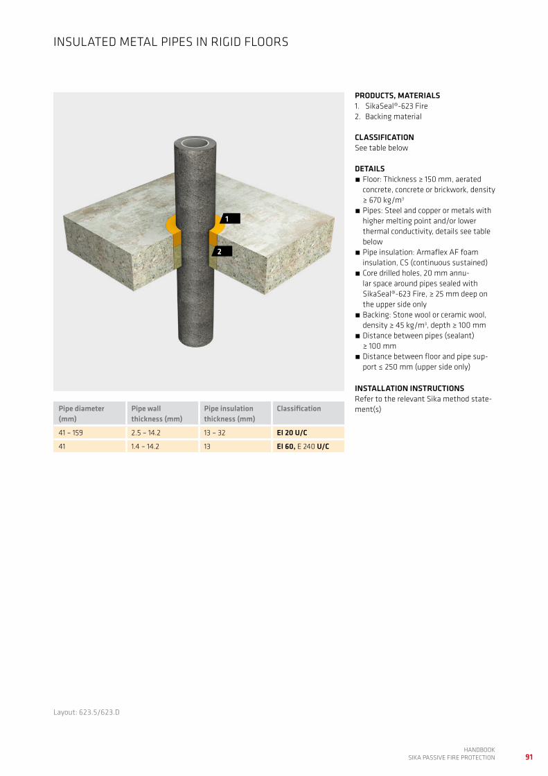
91HANDBOOK
SIKA PASSIVE FIRE PROTECTION
PRODUCTS, MATERIALS1. SikaSeal®-623 Fire 2. Backing material
CLASSIFICATIONSee table below
DETAILS Floor: Thickness ≥ 150 mm, aerated concrete, concrete or brickwork, density ≥ 670 kg/m3
Pipes: Steel and copper or metals with higher melting point and/or lower thermal conductivity, details see table below
Pipe insulation: Armaflex AF foam insulation, CS (continuous sustained)
Core drilled holes, 20 mm annu-lar space around pipes sealed with SikaSeal®-623 Fire, ≥ 25 mm deep on the upper side only
Backing: Stone wool or ceramic wool, density ≥ 45 kg/m3, depth ≥ 100 mm
Distance between pipes (sealant) ≥ 100 mm
Distance between floor and pipe sup-port ≤ 250 mm (upper side only)
INSTALLATION INSTRUCTIONSRefer to the relevant Sika method state-ment(s)
INSULATED METAL PIPES IN RIGID FLOORS
2
1
Layout: 623.5/623.D
Pipe diameter (mm)
Pipe wall thickness (mm)
Pipe insulationthickness (mm)
Classification
41 – 159 2.5 – 14.2 13 – 32 EI 20 U/C
41 1.4 – 14.2 13 EI 60, E 240 U/C

92HANDBOOK SIKA PASSIVE FIRE PROTECTION
PLASTIC AND MLC PIPES IN FLOORS, SMALL APERTURES
Short description Products Code Page
Plastic pipes in rigid floors SikaSeal®-627 Fire CollarSikacryl®-621 Fire
627.1 93
Plastic pipes in rigid floors Sikacryl®-623 FireBacking material
623.6 94
Plastic pipes in rigid floors SikaSeal®-628 Fire WrapSikacryl®-621 Fire
628.1 95
Plastic pipes in rigid floors SikaSeal®-629 Fire WrapSikacryl®-621 Fire
629.1 96

93HANDBOOK
SIKA PASSIVE FIRE PROTECTION
PRODUCTS, MATERIALS1. SikaSeal®-627 Fire Collar 2. Sikacryl®-621 Fire
CLASSIFICATIONEI 240 U/C for all pipes, see diagram below
DETAILS Floor: Thickness ≥ 150 mm, aerated concrete, concrete or brickwork, density ≥ 670 kg/m3
Pipe details see diagram below Core drilled holes, ≤ 10 mm annular space around pipes
Sikacryl®-621 Fire ≥ 12.5 mm deep, double seal
SikaSeal®-627 Fire Collar on the lower side of the floor
Distance between collars ≥ 100 mm Distance between floor and pipe sup-port ≤ 400 mm (upper side only)
INSTALLATION INSTRUCTIONSRefer to the relevant Sika method state-ment(s)
PLASTIC PIPES IN RIGID FLOORS, LOAD-BEARING
2
1
Layout: 627.1/627.A
Pipe diameter, collar diameter (mm)
PVC* PP PE**
Pipe wall thickness (mm)
32 1.8 2.9 2.9
40 1.8 2.9 2.9
50 1.8 2.9 2.9
55 2.3 – 3.0 2.9 – 4.4 2.9 – 4.4
63 2.3 – 3.0 2.9 – 4.4 2.9 – 4.4
75 3.1 – 4.8 2.8 – 6.7 2.8 – 6.7
82 3.1 – 4.8 2.8 – 6.7 2.8 – 6.7
90 4.2 – 7.4 2.7 – 10.0 2.7 – 10.0
100 4.2 – 7.4 2.7 – 10.0 2.7 – 10.0
110 4.2 – 7.4 2.7 – 10.0 2.7 – 10.0
125 6 3.1 3.1
140 6.1 – 7.5 3.5 – 8.0 3.9 – 5.8
160 6.2 – 9.5 4.0 – 14.6 4.9 – 9.5
* PVC-U, PVC-C ** PE HD, ABS, SAN + PVC See chapter “Pipe and insulation material”

94HANDBOOK SIKA PASSIVE FIRE PROTECTION
PRODUCTS, MATERIALS1. SikaSeal®-623 Fire 2. Backing material
CLASSIFICATIONPVC: EI 30 E 90 U/CPE: EI 60 U/CPP: EI 30 U/CSee diagram below
DETAILS Floor: Thickness ≥ 150 mm, aerated concrete, concrete or brickwork, density ≥ 670 kg/m3
Pipes details see diagram below Core drilled holes, 20 mm annu-lar space around pipes sealed with SikaSeal®-623 Fire, ≥ 25 mm deep on the both sides of the floor.
Backing: Stone wool or ceramic wool, density ≥ 45 kg/m3, depth ≥ 100 mm
Distance between pipes (sealant) ≥ 100 mm
Distance between floor and pipe sup-port ≤ 250 mm (upper side only)
INSTALLATION INSTRUCTIONSRefer to the relevant Sika method state-ment(s)
PLASTIC PIPES IN RIGID FLOORS
1
1
2
Layout: 623.6/623.E
Pipe diameter / pipe wall thickness diagram
Pipe
wal
l thi
ckne
ss (m
m)
2
4
6
8
0
10
12
Pipe diameter (mm)
3.6
3010 50 70 90 114 125110 130
8.1
4.1
2.0
40
2.1
11.4 11.4
7.68.1
10.710.7
PE PVC PP

95HANDBOOK
SIKA PASSIVE FIRE PROTECTION
PRODUCTS, MATERIALS1. SikaSeal®-628 Fire Wrap
(SikaSeal®-629 Fire Wrap alternatively)2. Sikacryl®-621 Fire
CLASSIFICATIONPVC: EI 60 U/CPP, PE: EI 120 U/CDetails see diagram below
DETAILS Floor: Thickness ≥ 150 mm, aerated concrete, concrete or brickwork, density ≥ 670 kg/m3
Pipe details see diagram below Core drilled holes, annular space around pipes see table below
SikaSeal®-628 Fire Wrap according to pipe diameter on both sides; alternati-vely SikaSeal®-629 Fire Wrap according to table below on both sides
Sikacryl®-621 Fire 5 mm deep on both sides
Distance between pipes (wrap) ≥ 100 mm
Distance between floor and pipe sup-port ≤ 400 mm (upper side only)
INSTALLATION INSTRUCTIONSRefer to the relevant Sika method state-ment(s)
PLASTIC PIPES IN RIGID FLOORS
2
1
1
Pipe diameter (mm)
Annular space (mm)
Numbers of layers of SikaSeal®-629 Fire Wrap
32 – 50 4 1
50 – 82 6 2
82 – 115 8 3
115 – 160 10 4
160 – 200 12 5
200 – 250 14 6
Layout: 628.1/628.A
Pipe diameter / pipe wall thickness diagram
Pipe
wal
l thi
ckne
ss (m
m)
50 70 90 110 130125 150 170
2
4
6
8
0
12
16
Pipe diameter (mm)
200190
14
10
18
1.8
2.9
17.1 17.1
3.93.1
9.6
11.4
9.6
11.4
7.7
4.9
PE PVC PP

96HANDBOOK SIKA PASSIVE FIRE PROTECTION
PRODUCTS, MATERIALS1. SikaSeal®-629 Fire Wrap2. Sikacryl®-621 Fire
CLASSIFICATIONPVC: EI 60 U/CPE: EI 240 U/CPP: EI 120 U/CDetails see diagram below
DETAILS Floor: Thickness ≥ 150 mm, aerated concrete, concrete or brickwork, density ≥ 670 kg/m3
Pipe details see diagram below Core drilled holes, annular space around pipes see table below
SikaSeal®-629 Fire Wrap according to table below in the middle of the floor or lower
Sikacryl®-621 Fire 10 mm deep on the upper side using a PE backer rod for large pipe diameters
Distance between pipes (wrap) ≥ 100 mm
Distance between floor and pipe sup-port ≤ 400 mm (upper side only)
INSTALLATION INSTRUCTIONSRefer to the relevant Sika method state-ment(s)
PLASTIC PIPES IN RIGID FLOORS
2
1
Layout: 629.1/629.A
Pipe diameter (mm)
Annular space (mm)
Numbers of layers of SikaSeal®-629 Fire Wrap
32 – 50 6 2
50 – 82 10 4
82 – 115 14 6
115 – 160 18 8
160 – 200 22 10
200 – 250 26 129.6
18.2 18.2
10
14
18
Pipe diameter / pipe wall thickness diagram
Pipe
wal
l thi
ckne
ss (m
m)
50 70 90 110 130 150 170
2
4
6
8
0
12
16
Pipe diameter (mm)
200190
2.43
9.6
7.7
4
4.9
20
PE PVC PP

97HANDBOOK
SIKA PASSIVE FIRE PROTECTION
NOTES

98HANDBOOK SIKA PASSIVE FIRE PROTECTION
NOTES


IND
US
TRY/
FIR
E P
RO
TECT
ION
HA
ND
BO
OK
UK
VER
. 1
JULY
20
20
The information, and, in particular, the recommendations relating to the application and end use of Sika® products, are given in good faith based on Sika’s current knowledge and experience of the products when properly stored, handled and applied under normal conditions. In practice, the differences in materials, substrates and actual site conditions are such that no warranty in respect of merchantability or of fitness for a particular purpose, nor any liability arising out of any legal relationship whatsoever, can be inferred either from this information, or from any written recommendations, or from any other advice offered. The proprietary rights of third parties must be observed. Please refer to our homepage www.sika.co.uk for our current standard terms & conditions applicable to all orders. Users should always refer to the most recent issue of the Product Data Sheet for the product concerned, copies of which will be supplied on request.
SIKA FULL RANGE SOLUTIONS FOR CONSTRUCTION:
LIQUID APPLIED ROOFING
SINGLE PLY ROOFING CONCRETE CONCRETE REPAIR BUILDING FINISHINGSTRUCTURAL STRENGTHENING
JOINT SEALING FLOORINGFAÇADE STRUCTURAL ADHESIVES
INDUSTRY DISTRIBUTION
BITUMINOUS ROOFING
WATERPROOFING
WHO WE ARESika Limited and Sika Ireland Limited are part of the global Sika Group, specialising in the manufacture and supply of chemical based products. Sika has a leading position in the development and production of systems and products for bonding, sealing, damping, reinforcing, and protecting in the building sector and the motor vehicle industry. Sika has subsidiaries in 101 countries around the world and manufactures in over 300 factories. With more than 25,000 employees Sika generates annual sales of CHF 8.1 billion (£6.6 bn). We are also committed to providing quality, service, safety and environmental care.
In the UK and Ireland, we provide market-leading solutions for concrete, waterproofing, roofing, flooring, refurbishment, sealing & bonding, and industry, and have manufacturing sites in Welwyn Garden City, Preston, Leeds. Wishaw and Dublin with more than 1000 employees and a turnover of more than £270 million.
SIKA LIMITEDHead OfficeWatchmeadWelwyn Garden CityHertfordshire, AL7 1BQUnited Kingdom
ContactPhone +44 1 707 394444Fax +44 1 707 329129E-Mail [email protected] @SikaLimited
FOR FURTHER INFORMATION:Contact John Gardner Mobile: 07881 379400or email: [email protected]