
Signalling/IN Server architecture for a broadband SSP server architecture for a broadband SSP 173...
12
14 Signalling/IN Server architecture for a broadband SSP D.Blaiotta(JJ, S.Daneluzzl 1 J, D.Fava(JJ, D.Lento(2), M Varisco(JJ (lJ Ita/tel, (JJ CSELT Contact Person: Danilo Fava, Central R&D Labs (C02), 20019-Settimo Milanese (MI) -Italy, Phone +39.2.43889116, Fax + 39.2.43887989, E-mail: [email protected] Abstract This paper describes a Signalling/IN Server taking into account the adopted architectural and implementation solutions. The Signalling/IN Server takes part in a Broadband Service Switching Point realised in the framework of the European research project INSIGNIA (IN and B-ISON Signalling Integration on ATM Platforms). The aim of the INSIGNIA project is to defme and implement an advanced IN and B-ISON signalling integration for satisfying users' requirements in terms of multimedia and broadband applications. The paper focuses on the B- SSP network element that integrates an evolved version of both the Service Switching Function and the Call Control Function. The core of the adopted functional model is the Switching State Model, which presents an abstract view of the network resources involved in the service provisioning. Keywords ATM, Broadband Signalling , Intelligent Network, Service Switching Point INTRODUCTION The ITU standardisation bodies have been defming a signalling system able to manage the network resources in order to support wideband services. The services Broadband Communications P. Kiihn & R. Ulrich (Eds.) © 1998 IFIP. Published by Chapman & Hall
Transcript of Signalling/IN Server architecture for a broadband SSP server architecture for a broadband SSP 173...

14 Signalling/IN Server architecture for a broadband SSP
D.Blaiotta(JJ, S.Daneluzzl1J, D.Fava(JJ, D.Lento(2), M Varisco(JJ (lJ Ita/tel, (JJ CSELT Contact Person: Danilo Fava, Central R&D Labs (C02), 20019-Settimo Milanese (MI) -Italy, Phone +39.2.43889116, Fax + 39.2.43887989, E-mail: [email protected]
Abstract This paper describes a Signalling/IN Server taking into account the adopted architectural and implementation solutions. The Signalling/IN Server takes part in a Broadband Service Switching Point realised in the framework of the European research project INSIGNIA (IN and B-ISON Signalling Integration on A TM Platforms). The aim of the INSIGNIA project is to defme and implement an advanced IN and B-ISON signalling integration for satisfying users' requirements in terms of multimedia and broadband applications. The paper focuses on the BSSP network element that integrates an evolved version of both the Service Switching Function and the Call Control Function. The core of the adopted functional model is the Switching State Model, which presents an abstract view of the network resources involved in the service provisioning.
Keywords A TM, Broadband Signalling , Intelligent Network, Service Switching Point
INTRODUCTION
The ITU standardisation bodies have been defming a signalling system able to manage the network resources in order to support wideband services. The services
Broadband Communications P. Kiihn & R. Ulrich (Eds.) © 1998 IFIP. Published by Chapman & Hall

172 Part A Broadband Technologies, Architectures and Network Design
development increases in accordance with the signalling system, but in order to optimally realise such services, the network has to provide a higher level of intelligence than juSt the establishment of point-to-point connections. This paper reports on results of an European ACTS research project that implements and demonstrates an advanced architecture integrating IN and B-ISON signalling. The project INSIGNIA, using available end systems and taking a Broadband ISDN network as its starting point, develops prototypes of Broadband Service Switching Point (B-SSPs), Broadband Service Control Point (B-SCPs) and Broadband Intelligent Peripheral (B-IP) in different National Hosts. In order to carry out trials with real end users, attractive multimedia application services have been made available that make use of the advanced network services. The three selected kinds of services are: Video-on-Demand, Broadband Video Conference and Broadband Virtual Private Network. The INSIGNIA project experiments broadband multimedia services handled by IN in five different sites interconnected by European A TM facilities : Madrid, Milan, Munich, Turin and Berlin (remote user for the Munich site).
In the next section, an introduction inside the functional architecture of INSIGNIA is given. Special emphasis is put throughout this paper on the central network element that provides the switching functionality (B-SSP). The following section describes the B-SSP external Server entity, and the next one gives an overview of the object oriented model solution adopted for the Italian B-SSP software implementation. The last section focuses on the foreseen developments for the Server architecture.
COMMON DESIGN OF THE B-SSP
INSIGNIA network elements The INSIGNIA architecture of a Broadband IN resumes and widens the classical IN. The main equipment involved in the INSIGNIA base structure are listed below.
• SERVICE CONTROL POINT (SCP). It is an intelligent server computer, as in classical IN, on which the Service Logic programs run in order to guarantee the calVconnection configurations. Compared to the classical SCP concept the INSIGNIA SCP has got an advanced communication level with B-SSP, based on an object oriented model of Service Logic instead of simple call state dialogue.
• SERVICE SWITCHING POINT (SSP). It is the switching network element able to support UNIINNI signalling dialogue and with service independent IN functionality.
• END SYSTEMS AND SPECIAL DEVICES. They change in accordance with the involved service, but since for multimedia applications PC terminals are commonly used as end system rather than telephone equipment, a service is supported in a distributed manner where program parts reside on the host

Signalling/IN server architecture for a broadband SSP 173
system. This increased users' capability drives to an SCP overload concerning its user interaction. For this aim a special network element has been introduced: the 8-IP. It acts as a server that frees the SCP from heavy service computations, and carries out multimedia communication with the user.
B-SSP Functional Model The design of the components, which have been developed for the INSIGNIA 8-SSPs, covers the functional entities of a Service Switching Function (SSF) and a Call Control Function (CCF).
Figure 1 The ltaltei/CSEL T 8-SSP functional Model.
In more detail, the design of the SSF comprises aspects of the SCP access handling, the processing ofB-INAP messages, the realisation ofTCAP, SCCP and MTP3 protocol layers, the Switching State Model (SSM), the handling of Detection Points (DP) and the interaction with the CCF. The design of the CCF has to consider the Basic Call State Model (BCSM), the handling of the NNIIUNI signalling and the establishment of A TM VC connections.
In Figure I the functional model used for the INSIGNIA B-SSP is depicted. It is based on the models defmed in ITU-T Recommendations for IN Capability Set 1 (CS-1) [ITU-T, Rec. Q.l214] and the Draft Recommendations for IN Capability Set 2 (CS-2) [ITU-T, Draft Rec. Q.l224].
Both the INSIGNIA SSF and CCF are different from the corresponding IN CS-1 functional blocks. In fact CCF is split in two levels, which are the Call Control and the Bearer Connection Control in order to make the IN model adequate for the support of advanced B-ISON calls. The SSF achieves the capability of handling the session concept introduced in a complex service configuration to solve the problem of the call/connection correlation. Inside the SSF, the IN Switching

174 Part A Broadband Technologies, Architectures and Network Design
Manager provides an object oriented session model, and then offers an abstract view of the whole call configuration to SCP. The BCSM model becomes valid only for the Basic Call Manager and its interaction with the IN Switching Manager. The design of the IN functional entities is developed according to the Object Modeling Technique (OMT) object oriented methodology [Blama, 1991].
THE ITALTEUCSELT B-SSP ARCIDTECTURE
The ItalteVCSEL T B-SSP is built around two subsystems.
• The Signalling and IN server, which is the same for both B-SSPs. • The A TM switching platform, which presents some differences according to
equipment availability in both premises.
The Signalling/IN server hosts the protocols and the applications which enable the handling of calls coming from the users and from the A TM network. The A TM switching platform offers the access ports for user and network connections and the capabilities needed in order to interconnect them. In addition, commands performing the establishment and tear down of connections are accepted from the signalling/IN subsystem. The Signalling/IN subsystem communicates with the A TM switching platform via: an STM 1 optical link. The A TM switching platform collects signalling from each user/network interface and presents it to the link towards the signalling/IN server by means of previously built cross-connections. After elaborating signalling, the server instructs the switching platform in order to establish/tear down connections between the users. This process takes place via the Ethernet connection between the two subsystems making up the ItalteVCSEL T B-SSP.
ATM Switching platform The Italtel switching platform used for the first trial is an Italtel prototype (UT -ASM). The system accepts A TM cells on three different underlying supports, namely, optical STMI, electrical E3 and optical TAXI on both user and network ports. The combination of UT-ASM and the signalling server provides switched A TM connections to the Milan site. The CSELT platform is based on the FORE Systems local A TM switch ASX200E. As the control software is installed on an external workstation, the FORE switch provides only the capability to realise connections between the requested end points. This functionality is accessed, for both the two A TM switching platform, by means of SNMP hidden in an API, that translates the commands issued by the signalling process in the correspondent SNMP dialogue. The adoption of this API allows the use of different switching fabric controlled by signalling.
Signalling/IN server architecture for a broadband SSP 175
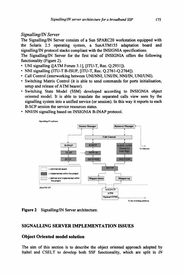
Signalling/IN Server The Signalling/IN Server consists of a Sun SPARC20 workstation equipped with the Solaris 2.5 operating system, a SunATM155 adaptation board and signalling/IN protocol stacks compliant with the INSIGNIA specifications. The Signalling/IN Server for the first trial of INSIGNIA offers the following functionality (Figure 2). • UNI signalling ([ATM Forum 3.1], [ITU-T, Rec. Q.2931]). • NNI signalling (ITU-T B-ISUP, [ITU-T, Rec. Q.2761-Q.2764]). • Call Control (interworking between UNIINNI, UNIIIN, NNIIIN, UNI/UNI). • Switching Matrix Control (it is able to send commands for ports initialisation,
setup and release of A TM bearer). • Switching State Model (SSM) developed according to INSIGNIA object
oriented model. It is able to translate the separated calls view seen by the signalling system into a unified service (or session). In this way it reports to each B-SCP session the service resources status.
• NNIIIN signalling based on INSIGNIA B-INAP protocol.
D·--- -~- ... pnljocl o --.... ~-
... pnljocl
s-ATJIISS
Figure 2 Signalling/IN Server architecture.
, ............ ,.._
SIGNALLING SERVER IMPLEMENTATION ISSUES
Object Oriented model solution
The aim of this section is to describe the object oriented approach adopted by Italtel and CSELT to develop both SSF functionality, which are split in IN

176 Part A Broadband Technologies, Architectures and Network Design
Switching Manager (SM) and SCF Access Manager (AM), and CCF functionality. In Figure 3 the CCF/SSF and SSF/SCF interface classes are shown.
A BCSM contains several DPs and it is assigned to each Call Control object that represents one basic call. On reaching an armed Trigger DP during the call processing, a Session object is created. A specific DP can trigger only one IN Service, represented by a Session, because no interaction between different IN services is provided for the first trial. Each instance of the Session class is in oneto-one correspondence with an instance of the SCF AM class. Communication between SCF and SSF is represented by the one-to-one association between SSF AM and SCF AM.
Figure 3 INSIGNIA IN object model.
Basic call handled within the CCF is represented by the objects inside the SSM. The CCF/SSF relationship is represented by two associations: the already mentioned relationship between DP and Session classes and the relationship between Call Control and Session classes. Since a session is an association between calls/connections for the deployment of a single IN service, many Call Control objects can deal with a Session object. When a SCP-initiated call is established, the Session object creates, inside the SSM, the objects that represent the corresponding network elements involved in the call. At the same time a new corresponding Call Control instance is created within the CCF.
CCF description The CCF implements all the functionality needed to handle calls and, in the INSIGNIA framework, the dialogue with the IN entities.
The core section of this model is represented by the Call View that contains the information related to a particular call instance. The Call View model was derived by the one specified and implemented during the RACE MAGIC project.
In more details, this model combines the abstract representation of the requested service with its real implementation (see figure 4). The classes res (l'eleCommunication Service), Party, USM (User Service Module) and PartyLevel give a fJrSt view of the service, highlighting the Parties involved in the service,

Signalling/ IN server architecture for a broadband SSP 177
which resources (USM) they are sharing and the relationship (Party Level) between the Parties and the resources. The other classes provide a more detailed description of the resources needed in the provision of the service. The ASM (Abstract Service Module) links the USM with the connections' description. The SM (Service Module) stores a description of the user information transported in the related connection while the characteristics (i.e., in terms of bandwidth) are stored in the CE (Connection Element) class. In the INSIGNIA framework, the TCS class contains also the Detection Point class. This class represents the core part of the BCSM and is used in the handling of IN calls to synchronise the interaction with the IN entities.
Figure 4 CCF object model.
At this point suppose that the requested service is the TV Distribution where a user wants to be connected to a TV station and suppose that the audio and video information is transported in different connections. From the user point of view, this is express in a TV channel request. The Call View will represent this service as in the following: TCS: TV Distribution USM X: TV channel ASM: TV channel is composed by two connections Party A: User SMI: this connection carries the video information Party Level A: User using USM X CE I: bandwidth and other informations about connection Party B: TV Station 1 PartyLevel B: TV Station using USM SM 2: this connection carries the audio information X CE 2: bandwidth and other informations about connection
2
The Interface class provide the functionality to translate the signalling primitives coming from the protocol stacks in modifications in the Call View and vice-versa. As shown in the model, the Interface class is a superclass and there is a derived class for each protocol stack.
• InterfaceQ2931: handles the dialogue with the UNI protocol stack. • InterfaceBISUP: handles the dialogue with the NNI protocol stack. • InterfaceiN: handles the dialogue with the SSM entity.

178 Part A Broadband Technologies, Architectures and Network Design
In general, the aim of this class is to offer a unique interface to the CCF core in order to preserve the core functions from the underlying protocols. If in the future a new protocol will be specified, the only adoption to the whole CCF model is a new derived Interface call specialised to dialogue with this new protocol.
The FSMState class implements the Finite State Machine of the CCF. There is a subclass for each state of the CCF and each class implements the operations that have to be performed on the Call View when the call is in that state. The Router class manages the routing tables and provides routing information to the other classes of the CCF. The Resource Manager class handles the API used to control the switching fabric. The Coordinator class, as suggested by its name, coordinates the functions performed by all the other classes.
SSM description The IN SSM provides an object oriented description of SSF/CCF IN calVconnection processing in terms of IN calVconnection states. The information flows between SSF and SCF are based on the SSM. The SSM performs the following functions:
• reception of incoming signals from the CCF and the IN AM; • translation of external signals into appropriate actions on the SSM objects; • transmission of signals towards the CCF and IN AM; • maintenance of the SSM data structures related to the Session and to the Session
objects.
It therefore contains objects that are abstractions of switching and transmission resources. For an integration of IN with B-ISON, the SSM becomes the main concept since it provides a model for the complex calVconnection configurations that may appear in B-ISON. The complex call connection configurations are represented in the SSM with the Session object. The IN Switching Manager structure is composed of the following object classes and relationships (figure 5).
• SMcoordinator class: it is instantiated only once in the SSF, and coordinates the dispatching of the B-INAP operations and CCF/SSF commands to the addressed session or call. It is able to coordinate all session and interface instances.
• Session class: it has two different meanings. From an IN point of view the Session is an instance of the provided service, (i.e. the VOO service). In a BISON perspective the session is the composition of resources needed to support the service.
• Party Class: it is the representation of a calling user, a called user or a network element, (i.e. the .B-SCP).
• Bearer Class: it is the abstract view of an end-to-end connection between two Parties.

Signalling! IN server architecture for a broadband SSP 179
• Leg Class: it is the representation of the path communication between the B-SSP and the Party.
• Interface Class: it allows to have an abstract view of the communication between the IN Switching Manager and the outside world. It is specialised in two subclasses: InterfaceToBCM (that handles the link towards the Basic Call Manager) and InterfaceToAM (that allows the link towards the SCF Access Manager).
• -" SMcoordinalor • - ... Session ..._ToiCM lnlerface ....._Ta.t.M
........ o i~D _ ... -o ~To6ellian0 •n~.-:eo
··········· ......... -0 -o -----==-,__£__ __ ........
~ToBCMI I lnlerf
~~ .. r ' I 1..00() I i ,,_. joins
I 1 sop o sop o
-------. ~ • I e.rer Party
I=D Lag ~--------~~~
IOgiD
I
powtyiD I··· ~·. - -j-.o ..... 1_,.--.ngLJsl o t..ao I Porty 0 I ~·· ·~·· ·~·· _T.........,.....O
I -.ouo
<.;> ......... ----,-----IS~posedby Is connected by
Figure 5 OMT-based Session Manager design.
The main attributes of the SSM objects are described in more details in Table I.
Table 1 Objects and identifiers
OBJECT OBJECT AJTRIBUTE AJTRIBUTE A JTRIBUTE IDENTIFIER NAME IDENTIFIER IDENTIFIER VALVES Session Session ID None Party Party ID Virtual Party Is Virtual FALSE/TRUE
Bearer BCID Bearer Status Status BEING SETUP I SETUP I Connection BEING RELEASED
Leg Leg ID Leg Status Status PENDING/ DESTINED I JOINED I ABANDONED I REFUSED
The attribute "Is_ Virtual" indicates whether the respective party object is representing a network element (i.e., the SCP for the INSIGNIA first trial) or a true party associated with an end system.
The "Status" attributes of BearerConnection and Leg represent the status of the respective object with respect to call processing. There is a relationship between the status attributes of the bearer connection and the legs. The status of the bearer connection is BEING SETUP, as long as the status attributes of all corresponding

180 Part A Broadband Technologies, Architectures and Network Design
legs are not JOINED. Only if all corresponding legs have status JOINED, the bearer connection will have status SETUP.
The IN-SSM view, including relationships between objects, is communicated from B-SSP to B-SCP (or vice versa) through information elements in the Information Flows. The two ownership relations of the SSM class diagram (between Party and Session as well as between Party and BearerConnection), however, are considered to be local at the SSP for the first trial. This means that the ownership relationships are not visible to the SCF, and the Information Flows for the frrst trial do not transport parameters related to session or bearer ownership.
AM coordinator lr.-:tiDnlilt
• <) -TaTCAP -ToSM
Transaction I <> -I -ID
··-~=Hr • T- State
~· =Mot is in ls.eo
~~0
1'-WlitingFor
kiiiSiale SCFRospansa State
-0 Wlllllngi'O'SCF •• O --o Wllilif'GFarSCF ... O ... . ..
Interface .,_D .. -o ·-o ~
I lnterfaceToTCAP
1-TaTCAPO "1-TaTCAPO ...
Wllititv;/f'OI SSMSIIIIaChllngeAn SCFCommand Stale
WoilingFcr--.o WdlgFarss-.. o ...
I nterlaceToSM
~-~ OSMO OSMO --T
...
Figure 6 OMT-based Access Manager design.
AM description The SCF AM handles the communication between the SSF and SCF. It locates the required IN Service in A TM Network and sends messages to/receives messages from the B-SCF. This communication is based on the SSM and therefore on the physical plane is performed through a Broadband Intelligent Network Application Protocol (B-INAP), completely defmed in INSIGNIA project. In fact from a methodological point of view the B-INAP specification is structured in a way similar to IN CS-1 INAP (such as use of ASN.l notation language as abstract syntax and BER (Basic Encoding Rules) as encoding rules), but the content of Information Flows exchanged between B-SSF and B-SCF reflects the abstrar.t object view of SSM. Since the B-SCF handles only the objects included in the model (session, party, bearer connection, leg), the SCF/SSF interaction is in terms of IN SSM events (SSM state changes) and not in terms of Call Model events (BCSM state changes).The OMT approach has been adopted also for the design of the SCF Access Manager.

Signalling/IN server architecture for a broadband SSP 181
The structure of this functional block shown in figure 6 foresees the following object classes and relationships.
• The AMcoordinator class is instantiated only once in the SSF to coordinate the handling ofthe B-INAP operations from/to the SM and of the messages from/to TCAP, addressing the appropriate instance. It is able to coordinate all transactions, states and interface instances.
• The Interface class allows to abstract the communication between the SCF AM and the outside world; it is specialised in two subclasses: InterfaceToTCAP and InterfaceToSM.
• The lnterjaceToTCAP class represents the link towards the TCAP ASE. • The InterjaceToSM class represents the link towards the IN SM. • The Transaction class instance represents the current state of the communication
between the SSF and SCF for each active session instance. Each Transaction instance has a "is in" association with only one State subclass instance and this association changes during the transaction lifetime according to the AM dynamics.
• The State is the class that allows to describe all allowed transitions from the specific state to the destination states, depending on the received operation.
Server software architecture
The Signalling/IN Server software architecture is composed by software modules that may execute concurrently and message queues provide the mechanism that allows the communication between them.
The architecture of some software modules in B-SSP reflects their SOL description. In this case, the process evolves like a Finite State Machine, that is, performs specific operations only on the basis of its initial state and the input message. A module structured in such a way, takes advantage from facilities offered by ad-hoc developed tools and libraries. A code generator, starting from a description of the expected events (in terms of messages) and the associated state transition, performs the application framework in C language. This code contains the matrix that binds initial state, input message, function to be performed and ending state. This matrix is scanned by library routines allowing the operation flow control. The library routines allow the generation of several instances of the same process; instances may be created either at startup time or run-time and they may evolve independently (but not concurrently during state transitions). The adopted solution does not overload the host, since a new instance only needs allocation of little amount of memory. This memory is used to store information regarding state, timers and protocol dependent values. The software architecture allows the linkage of several modules into a single UNIX process. The communication between modules is always performed via library functions that are based on UNIX IPC

182 Part A Broadband Technologies, Architectures and Network Design
queues or on process internal queues, depending on whether the modules are parts of the same process or not. The library routines post the output messages into the destination queues and, when messages are received, schedule the execution of the associated routines. The binding between queues and software modules is statically detennined, and the routing of messages is done by analysing the message header that contains infonnation about source and destination module. Libraries also employ facilities to handle timers by sending messages to the involved instances when the requested timers expire. It has to be noticed that software modules that do not have a Finite State Machine structure, may use the library routines for interprocess communication without the need for modifications.
CONCLUSIONS AND FUTURE DEVELOPMENTS
This paper describes the external Signalling/IN Server characteristic of a Broadband SSP system realised with implementation solutions conceived according to the OMT approach. The B-SSP described in this paper has been used in the first INSIGNIA trail in order to support the B-VC and VOD services. The experimentation allows to confinn new IN based solutions for multimedia applications. In particular it will be possible to analyse, in a wide area network, the IN solution efficiency concerning some services otherwise provided with less advanced network structures. An example of these is the VOD service, which can also be supported according to other kinds of architectures. The IN solution provides a simplified service handling method and assures a fast way to enrich services, without necessarily modifying the end systems.
For the second trial (summer 1998) an upgrading towards a more sophisticated Server architecture is planned. First of all, the Server will be supplied with advanced B-ISDN Signalling aspects, compliant with the CS-2 study group standard, and also considerable for multimedia services. Porting of the software architecture on a real-time platfonn is also planned.
REFERENCES
ITU-T. (1993) Recommendation Q.l214. Study Group XI, Helsinki. ITU-T. (1996) Draft Recommendation Q.l224. Study Group XI, Nice. ITU-T. (1994) Recommendation Q.2931. Study Group XI, Geneva. ITU-T. (1994) Recommendation Q.2761-Q.2764. Study Group XI, Geneva. ATMU Forum. (1994) UNI Specification 3.1. Blama, M. and Rumbaugh, J. (1991) Object-Oriented Modelling and Design.
Prentice Hall, New Jersey.