
Signal Optimization and Rectenna Design for ... - Edinburgh/Member Presentations/S6... · Signal...
27
Apostolos Georgiadis Department of Microwave Systems and Nanotechnology Centre Tecnologic de Telecomunicacions de Catalunya (CTTC) Barcelona - Spain Signal Optimization and Rectenna Design for Electromagnetic Energy Harvesting and Wireless Power Transfer
Transcript of Signal Optimization and Rectenna Design for ... - Edinburgh/Member Presentations/S6... · Signal...

Apostolos GeorgiadisDepartment of Microwave Systems and NanotechnologyCentre Tecnologic de Telecomunicacions de Catalunya
(CTTC)Barcelona - Spain
Signal Optimization and Rectenna Design for Electromagnetic Energy Harvesting and
Wireless Power Transfer

2
Outline
• Introduction • Rectenna design
− Dual band− Load independent performance
• Signal design− Multi-sine − Chaotic− Mode locked oscillators
• Conclusion

3
CTTC, Castelldefels – BarcelonaFounded in 2001

4
CTTC, Castelldefels – Barcelona• Research staff: 35 Ph.D., 20 M.Sc, 3500-m2 building
• 3 Research Divisions: Comm. Systems, Comm. Networks, Comm. Technologies
• Department of Microwave Systems and Nanotechnology

5
CTTC, Castelldefels – Barcelona, SPAIN
• Energy Harvesting and RFID• Oscillator design including integrated
CMOS oscillators (Fig. 1)• Active antennas, phased arrays (Fig. 2),
retro-directive arrays (Fig. 3)• Substrate Integrated Waveguide (SIW) (Fig. 4)• Efficient Power Amplifier (Fig. 5)
Active microwave circuit design
Fig. 1. CMOS VCO for UWB-FM
Fig. 2. C-band Coupled Oscillator Reflectrarray prototype
Fig. 3. S-band retro-directive array.
Fig. 4. SIW circuits.
Fig. 5. Power Amplifier (SIW).

6
Rectenna Design
Reported UHF rectifier efficiencies for available input power levels in the order of 10 uW are near 20%, and increase to >50% for available power levels of 100uW.
Rectifier circuits: envelope detector, charge pump circuits
Schottky diodes, low / zero barrier diodes

7
Rectenna Design
Rectenna optimization using the RECEIVE antennaThevenin (or Norton) equivalent circuit
Multiple goal harmonic balance for optimizing the RF-DC conversion efficiency
Georgiadis, A.; Andia Vera, G.; Collado, A., "Rectenna design and optimization using reciprocity theory and harmonic balance analysis for electromagnetic (EM) energy harvesting," Antennas and Wireless Propagation Letters, IEEE , vol.9, no., pp.444,446, 2010

8
Rectenna Design
Georgiadis, A.; Andia Vera, G.; Collado, A., "Rectenna design and optimization using reciprocity theory and harmonic balance analysis for electromagnetic (EM) energy harvesting," Antennas and Wireless Propagation Letters, IEEE , vol.9, no., pp.444,446, 2010
Open circuit voltage maybe calculated using reciprocity theory
Harmonic balance for the optimization of the RF-DC conversion efficiency

9
Rectenna Design850 MHz/1850 MHz Dual Band Rectenna• Βroadband monopole antenna (0.7GHz - 6 GHz)
• Akaflex PCL3-35/75 μm with εr = 3.3 and tanδ = 0.08
• Silicon Schottky diode (Skyworks SMS7630)
• Coplanar waveguide matching network
• Optimization for input power of -20 dBm and RL=2.2 kΩ
Collado, A.; Georgiadis, A., "Conformal Hybrid Solar and Electromagnetic (EM) Energy Harvesting Rectenna," Circuits and Systems I: Regular Papers, IEEE Transactions on , vol.60, no.8, pp.2225,2234, Aug. 2013

10
Rectenna Design Optimization goals are used to maximize the RF-DC conversion efficiency at 915 MHz and 2.45 GHz = 48% and = 39% at 915 MHz
and 2.45 GHz, for Pin=0 dBm <1 % for Pin<-33 dBm
Niotaki, K.; Sangkil Kim; Seongheon Jeong; Collado, A.; Georgiadis, A.; Tentzeris, M.M., "A Compact Dual-Band RectennaUsing Slot-Loaded Dual Band Folded Dipole Antenna," Antennas and Wireless Propagation Letters, IEEE , vol.12, no., pp.1634,1637, 2013

11
Rectenna Design
• = 37% and = 20% at 915 MHz and 2.45 GHz for a power density of 1 uW/cm2
− 1 uW/cm2 corresponds to Pin=-9 dBm and Pin=-15 dBm at 915 MHz and at 2.45 GHz
[1] A. Collado, and A. Georgiadis, "Conformal Hybrid Solar and Electromagnetic (EM) Energy Harvesting Rectenna," IEEE Trans. Circuits Syst. I, Reg. Papers, vol. 60, no. 8, pp.2225,2234, Aug. 2013[2] B. L. Pham and A.-V. Pham, "Triple Bands Antenna and High Efficiency Rectifier Design for RF Energy Harvesting at 900, 1900 and 2400 MHz," in Proc. IEEE MTT-S Int. Microwave Symp., Seattle, WA, 2–7 June 2013.[3] V.Rizzoli, G. Bichicchi, A. Costanzo, F. Donzelli, and D. Masotti, "CAD of multi-resonator rectennafor micro-power generation," in Proc. Microwave Integrated Circuits Conference (EuMIC 2009), 28-29 Sept. 2009, pp.331–334.

12
Rectenna Design• Challenge: load and input power variation• Resistance compression networks
Y. Han, O. Leitermann, D.A. Jackson, J.M. Rivas, and D.J. Perreault, “Resistance Compression Networks forRadio-Frequency Power Conversion, ” IEEE Trans. on Power Electronics, vol. 22, no. 1, pp. 41-53, Jan. 2007.
100 101 102 1030
100
200
300
400
500
Load Resistance (Ohm)In
put R
esis
tanc
e (O
hm)
Load resistance variation: 3 Ohm – 1000 Ohm
Input resistance variation: 55 Ohm – 500 Ohm

13
Rectenna Design• Dual band metamaterial based resistance compression
network.
K. Niotaki, A. Collado, A. Georgiadis, “Dual band rectifier based on resistance compression networks,” in Proc.2014 IEEE MTT-S IMS, Tampa, 1-6 June 2014.
RF-D
C Co
nver
sion
Effic
ienc
y (%
)
RF-D
C Co
nver
sion
Effic
ienc
y (%
)
915 MHz 2.45 GHz

14
Signal Design
• Signals with time-varying envelope (PAPR > 0 dB) lead to higher rectifier RF-DC conversion efficiency
− Multi-sines (Durgin, Carvalho, Popovic, …)− Chaotic signals− White noise− Random modulation (multi-carrier)

15
Signal Design• First experiments: chaotic oscillator
433 MHz chaotic generator
Colpitts based chaotic generator
Bipolar transistor BFP183w
300 310 320 330 340time (nsec)
-0.5
-0.25
0
0.25
0.5
0 200 400 600 800-80
-60
-40
-20
0
frequency (MHz)
A. Collado, A. Georgiadis, "Improving Wireless Power Transmission Efficiency Using Chaotic Waveforms," in Proc. IEEE MTT-S IMS 2012, Montreal, 17-22 June 2012.

16
Signal Design
chaotic signal power[250 MHz – 600MHZ]
-6.5 dBm
Need to filter chaotic signal
One-tone signal power[250MHz – 600MHZ]
Total power of 1-tone signal selected to be equal to the chaotic signal total power in the bandwidth of the rectifier
A. Collado, A. Georgiadis, "Improving Wireless Power Transmission Efficiency Using Chaotic Waveforms," in Proc. IEEE MTT-S IMS 2012, Montreal, 17-22 June 2012.

17
Signal Design
A. Collado, A. Georgiadis, "Improving Wireless Power Transmission Efficiency Using Chaotic Waveforms," in Proc. IEEE MTT-S IMS 2012, Montreal, 17-22 June 2012.

18
Signal DesignSignal PAPR (dB)1-tone 3OFDM 12Whitenoise
13.7
Chaotic 14.8
PAPR[x(t)] ~ PAPR[e(t)] + 3 dB
A. Collado, A. Georgiadis, 'Optimal Waveforms for Efficient Wireless Power Transmission,' IEEE Microwave and Wireless Components Letters, 2014, to appear.

19
Signal Design
A. Collado, A. Georgiadis, 'Optimal Waveforms for Efficient Wireless Power Transmission,' IEEE Microwave and Wireless Components Letters, 2014, to appear.
RF-
DC
Con
vers
ion
Effic
ienc
y (%
)
rectifier operates at 433 MHzSkyworks SMS7630-02LF diode output load of 5.6 KOhm
20
Signal Design
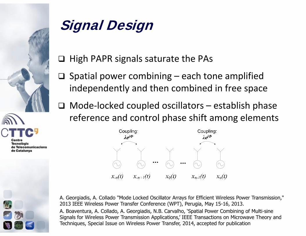
A. Georgiadis, A. Collado "Mode Locked Oscillator Arrays for Efficient Wireless Power Transmission," 2013 IEEE Wireless Power Transfer Conference (WPT), Perugia, May 15-16, 2013.A. Boaventura, A. Collado, A. Georgiadis, N.B. Carvalho, ‘Spatial Power Combining of Multi-sine Signals for Wireless Power Transmission Applications,’ IEEE Transactions on Microwave Theory and Techniques, Special Issue on Wireless Power Transfer, 2014, accepted for publication
High PAPR signals saturate the PAs
Spatial power combining – each tone amplified independently and then combined in free space
Mode-locked coupled oscillators – establish phase reference and control phase shift among elements

21
Signal Design
4x1 active antenna oscillator array at 6 GHz
Patch antenna aperture coupled to a VCO
A. Boaventura, A. Collado, A. Georgiadis, N.B. Carvalho, ‘Spatial Power Combining of Multi-sine Signals for Wireless Power Transmission Applications,’ IEEE Transactions on Microwave Theory and Techniques, Special Issue on Wireless Power Transfer, 2014, accepted for publication

22
Signal Design
A. Boaventura, A. Collado, A. Georgiadis, N.B. Carvalho, ‘Spatial Power Combining of Multi-sine Signals for Wireless Power Transmission Applications,’ IEEE Transactions on Microwave Theory and Techniques, Special Issue on Wireless Power Transfer, 2014, accepted for publication
Step1: 2 VCOs with 50 MHz spacing. Mixing products are created
Step2: 3 VCOs. The third one with a free running frequency corresponding to one of the mixing products
Step3: 4 VCOs. The fourth one with a free running frequency corresponding to one of the mixing products
23
Signal Design
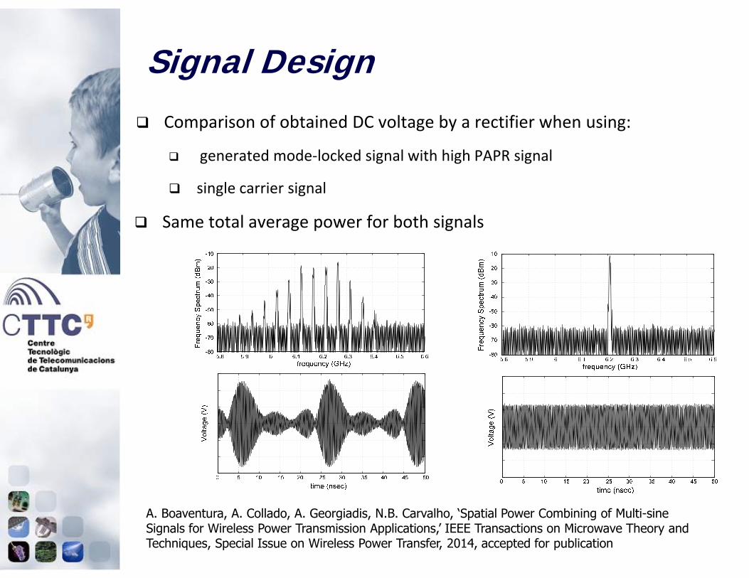
A. Boaventura, A. Collado, A. Georgiadis, N.B. Carvalho, ‘Spatial Power Combining of Multi-sine Signals for Wireless Power Transmission Applications,’ IEEE Transactions on Microwave Theory and Techniques, Special Issue on Wireless Power Transfer, 2014, accepted for publication
Comparison of obtained DC voltage by a rectifier when using:
generated mode-locked signal with high PAPR signal
single carrier signal
Same total average power for both signals

24
Signal Design
A. Boaventura, A. Collado, A. Georgiadis, N.B. Carvalho, ‘Spatial Power Combining of Multi-sine Signals for Wireless Power Transmission Applications,’ IEEE Transactions on Microwave Theory and Techniques, Special Issue on Wireless Power Transfer, 2014, accepted for publication
2
Power gain compares the obtained DC voltage by a rectifier when using the high PAPR signal in comparison with a one-tone signal
Improved performance when using the high PAPR mode-locked signal

25
Conclusion
Multi-band rectennas allow wider application
Reactive networks capable of minimizing rectenna efficiency sensitivity to load variation
High PAPR leads to higher efficiency
Spatial power combining for WPT transmitters

26
Cambridge Journal on Wireless Power Transfer
http://journals.cambridge.org/action/displayJournal?jid=WPT
Wireless Power Transfer (WPT) is the first journal dedicatedto publishing original research and industrial developmentsrelating to wireless power.
Kick-off issue to appear APRIL 2014
WPT will cover all methods of wireless power transfer andarticles will reflect the full diversity of applications for thistechnology, including mobile communications, medical implants,automotive technology, and spacecraft engineering.

27
Acknowledgement
EU Marie Curie projectSWAP, FP7 251557http://www.fp7-swap.eu/
Apostolos GeorgiadisDepartment of Microwave Systems and NanotechnologySenior Researcher Centre Tecnologic de Telecomunicacions de Catalunya (CTTC) Avda Carl Friedrich Gauss 7 08860 Castelldefels - Barcelona Spain
Email: [email protected] Google: https://sites.google.com/site/apostolosgeorgiadis1/home