Signal Encoding - Northeastern University College of ... · PDF fileWireless Networks Fall...
42
Wireless Networks Fall 2007 Signal Encoding CSG 250 Fall 2007 Rajmohan Rajaraman
Transcript of Signal Encoding - Northeastern University College of ... · PDF fileWireless Networks Fall...

Wireless Networks Fall 2007
Signal Encoding
CSG 250Fall 2007
Rajmohan Rajaraman
Wireless Networks Fall 2007
Reasons for Choosing EncodingTechniquesDigital data, digital signal
o Equipment less complex and expensive thandigital-to-analog modulation equipment
Analog data, digital signalo Permits use of modern digital transmission and
switching equipment
Wireless Networks Fall 2007
Reasons for Choosing EncodingTechniquesDigital data, analog signal
o Some transmission media will only propagateanalog signals
o E.g., unguided media
Analog data, analog signalo Analog data in electrical form can be
transmitted easily and cheaplyo Done with voice transmission over voice-grade
lines

Wireless Networks Fall 2007
Signal Encoding Criteria What determines how successful a receiver will be
in interpreting an incoming signal?o Signal-to-noise ratioo Data rateo Bandwidth
An increase in data rate increases bit error rate An increase in SNR decreases bit error rate An increase in bandwidth allows an increase in
data rate
Wireless Networks Fall 2007
Comparing Encoding Schemes
Signal spectrumo With lack of high-frequency components, less bandwidth
required• Spectral efficiency (also called bandwidth efficiency)
o With no dc component, ac coupling via transformerpossible
o Transfer function of a channel is worse near band edges
Clockingo Ease of determining beginning and end of each bit
position
Wireless Networks Fall 2007
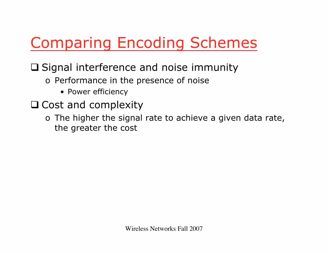
Comparing Encoding Schemes
Signal interference and noise immunityo Performance in the presence of noise
• Power efficiency
Cost and complexityo The higher the signal rate to achieve a given data rate,
the greater the cost

Wireless Networks Fall 2007
Digital Data to Analog Signals
Amplitude-shift keying (ASK)o Amplitude difference of carrier frequency
Frequency-shift keying (FSK)o Frequency difference near carrier frequency
Phase-shift keying (PSK)o Phase of carrier signal shifted


Wireless Networks Fall 2007
Amplitude-Shift Keying One binary digit represented by presence of
carrier, at constant amplitude Other binary digit represented by absence of
carrier
• where the carrier signal is Acos(2!fct)
( )
=ts( )tfA cπ2cos
0
1binary 0binary
Wireless Networks Fall 2007
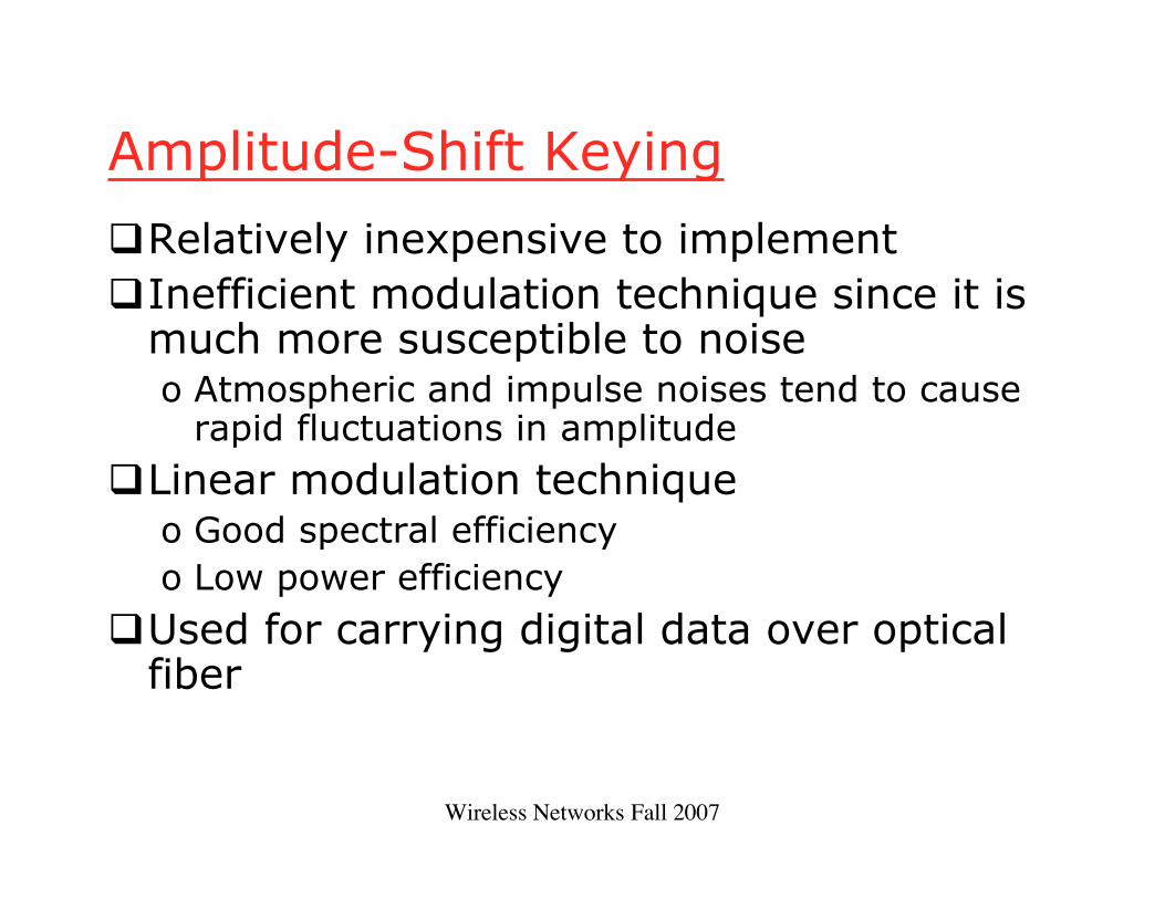
Amplitude-Shift Keying
Relatively inexpensive to implementInefficient modulation technique since it is
much more susceptible to noiseo Atmospheric and impulse noises tend to cause
rapid fluctuations in amplitude
Linear modulation techniqueo Good spectral efficiencyo Low power efficiency
Used for carrying digital data over opticalfiber

Wireless Networks Fall 2007
Binary Frequency-Shift Keying(BFSK) Two binary digits represented by two different
frequencies near the carrier frequency
• where f1 and f2 are offset from carrier frequency fc by equalbut opposite amounts
( )
=ts( )tfA 12cos π
( )tfA 22cos π1binary 0binary

Wireless Networks Fall 2007
Frequency-Shift Keying (FSK)
Less susceptible to error than ASKUsed for high-frequency (3 to 30 MHz)
radio transmissionCan be used at higher frequencies on LANs
that use coaxial cableAmplitude of the carrier wave is constant
o Power-efficient

Wireless Networks Fall 2007
Multiple Frequency-Shift Keying(MFSK) More than two frequencies are used More bandwidth efficient but more susceptible to
error
• f i = f c + (2i – 1 – M)f d• f c = the carrier frequency• f d = the difference frequency• M = number of different signal elements = 2 L
• L = number of bits per signal element
( ) tfAts ii π2cos= Mi ≤≤1

Wireless Networks Fall 2007
Multiple Frequency-Shift Keying(MFSK) To match data rate of input bit stream,
each output signal element is held for:Ts=LT seconds
• where T is the bit period (data rate = 1/T)
So, one signal element encodes L bits

Wireless Networks Fall 2007
Multiple Frequency-Shift Keying(MFSK)Total bandwidth required
2MfdMinimum frequency separation required
2fd=1/Ts
Therefore, modulator requires a bandwidthof
Wd=2L/LT=M/Ts

Wireless Networks Fall 2007
Multiple Frequency-Shift Keying(MFSK)

Wireless Networks Fall 2007
Phase-Shift Keying (PSK)
Two-level PSK (BPSK)o Uses two phases to represent binary digits
o Linear modulation technique
( )
=ts( )tfA cπ2cos( )ππ +tfA c2cos
1binary 0binary
=( )tfA cπ2cos
( )tfA cπ2cos−
1binary 0binary

Wireless Networks Fall 2007
Phase-Shift Keying (PSK)
Differential PSK (DPSK)o Phase shift with reference to previous bit
• Binary 0 – signal burst of same phase as previoussignal burst
• Binary 1 – signal burst of opposite phase to previoussignal burst
Wireless Networks Fall 2007
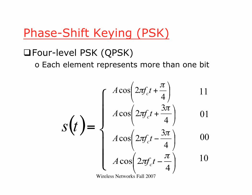
Phase-Shift Keying (PSK)
Four-level PSK (QPSK)o Each element represents more than one bit
( )
=ts
+4
2cosπ
π tfA c 11
+4
32cos
ππ tfA c
−4
32cos
ππ tfA c
−4
2cosπ
π tfA c
01
00
10
Wireless Networks Fall 2007
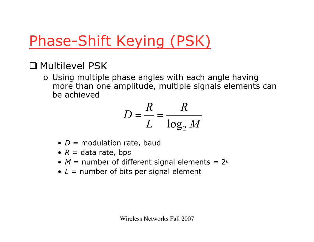
Phase-Shift Keying (PSK)
Multilevel PSKo Using multiple phase angles with each angle having
more than one amplitude, multiple signals elements canbe achieved
• D = modulation rate, baud• R = data rate, bps• M = number of different signal elements = 2L
• L = number of bits per signal element
M
R
L
RD
2log==

Wireless Networks Fall 2007
Performance
Bandwidth of modulated signal (BT)o ASK, PSK BT=(1+r)Ro FSK BT=2DF+(1+r)R
• R = bit rate• 0 < r < 1; related to how signal is filtered• DF = f2-fc=fc-f1

Wireless Networks Fall 2007
Performance
Bandwidth of modulated signal (BT)
o MPSK
o MFSK
• L = number of bits encoded per signal element• M = number of different signal elements
RM
rR
L
rBT
+=
+=
2log
11
( )R
M
MrBT
+=
2log
1

Wireless Networks Fall 2007
Quadrature Amplitude Modulation
QAM is a combination of ASK and PSKo Two different signals sent simultaneously on
the same carrier frequency
( ) ( ) ( ) tftdtftdts cc ππ 2sin2cos 21 +=

Quadrature Amplitude Modulation
Wireless Networks Fall 2007
Analog Data to Analog Signal
Modulation of digital datao When only analog transmission facilities are
available, digital to analog conversion required
Modulation of analog datao A higher frequency may be needed for effective
transmissiono Modulation permits frequency division
multiplexing

Wireless Networks Fall 2007
Modulation Techniques
Amplitude modulation (AM)Angle modulation
o Frequency modulation (FM)o Phase modulation (PM)

Wireless Networks Fall 2007
Amplitude Modulation
( ) ( )[ ] tftxnts ca π2cos1+=
Amplitude Modulation
• cos2πfct = carrier• x(t) = input signal• na = modulation index (< 1)
– Ratio of amplitude of input signal to carrier
o Double sideband transmitted carrier (DSBTC)
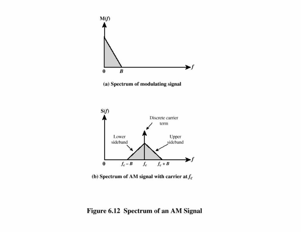

Wireless Networks Fall 2007
Amplitude Modulation
Transmitted power
• Pt = total transmitted power in s(t)• Pc = transmitted power in carrier
+=2
12a
ct
nPP

Wireless Networks Fall 2007
Single Sideband (SSB)
Variant of AM is single sideband (SSB)o Sends only one sidebando Eliminates other sideband and carrier
Advantageso Only half the bandwidth is requiredo Less power is required
Disadvantageso Poor performance in fading channels

Wireless Networks Fall 2007
Angle Modulation
Angle modulation
Phase modulationo Phase is proportional to modulating signal
• np = phase modulation index
( ) ( )[ ]ttfAts cc φπ += 2cos
( ) ( )tmnt p=φ

Wireless Networks Fall 2007
Angle Modulation
Frequency modulationo Derivative of the phase is proportional to
modulating signal
• nf = frequency modulation index
( ) ( )tmnt f='φ
Wireless Networks Fall 2007
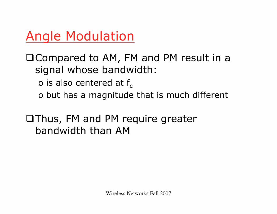
Angle Modulation
Compared to AM, FM and PM result in asignal whose bandwidth:o is also centered at fco but has a magnitude that is much different
Thus, FM and PM require greaterbandwidth than AM

Wireless Networks Fall 2007
Angle Modulation
Carson’s rule
where
The formula for FM becomes
( )BBT 12 += β
BFBT 22 +Δ=
FMfor
PMfor
2
=Δ=
B
An
B
F
An
mf
mp
π
β

Wireless Networks Fall 2007
Analog Data to Digital Signal
Digitization: Often analog data areconverted to digital form
Once analog data have been converted todigital signals, the digital data:o can be transmitted using NRZ-Lo can be encoded as a digital signal using a code
other than NRZ-Lo can be converted to an analog signal, using
previously discussed techniques

Wireless Networks Fall 2007
Analog data to digital signal
Pulse code modulation (PCM)Delta modulation (DM)

Wireless Networks Fall 2007
Pulse Code Modulation
Based on the sampling theoremEach analog sample is assigned a binary
codeo Analog samples are referred to as pulse
amplitude modulation (PAM) samples
The digital signal consists of block of nbits, where each n-bit number is theamplitude of a PCM pulse


Wireless Networks Fall 2007
Pulse Code Modulation
By quantizing the PAM pulse, originalsignal is only approximated
Leads to quantizing noiseSignal-to-noise ratio for quantizing noise
Thus, each additional bit increases SNR by6 dB, or a factor of 4
dB 76.102.6dB 76.12log20SNR dB +=+= nn

Wireless Networks Fall 2007
Delta Modulation
Analog input is approximated by staircasefunctiono Moves up or down by one quantization level (δ)
at each sampling interval
The bit stream approximates derivative ofanalog signal (rather than amplitude)o 1 is generated if function goes upo 0 otherwise
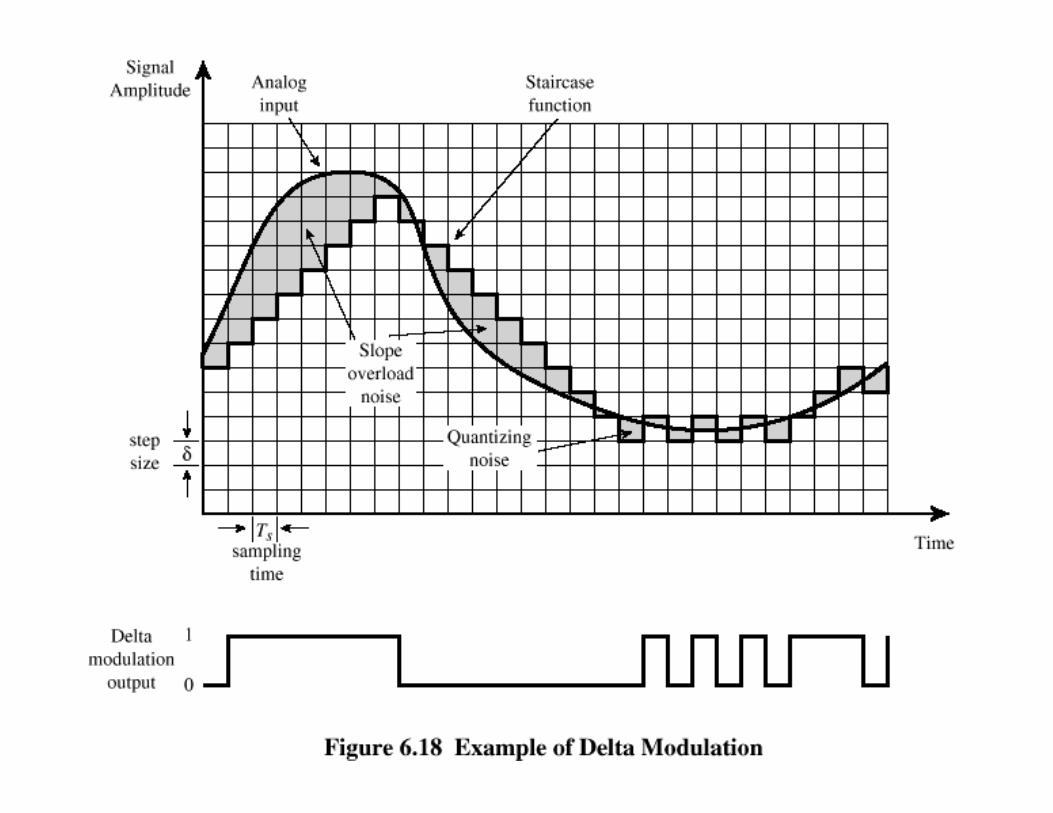
Delta Modulation

Wireless Networks Fall 2007
Delta Modulation
Two important parameterso Size of step assigned to each binary digit (δ)o Sampling rate
Accuracy improved by increasing samplingrateo However, this increases the data rate
Advantage of DM over PCM is thesimplicity of its implementation