1 Lecture 3 Data Encoding and Signal Modulation Introduction Data Encoding and Signal Modulation...
40
1 Lecture 3 Data Encoding and Signal Modulation • Introduction • Data Encoding and Signal Modulation • Advantages of Signal Modulation • Amplitude Modulation • Amplitude Modulation of Digital Signals • Reducing Power and Bandwidth of AM Signals • Frequency Modulation • Power and Bandwidth of FM Signals • Conclusion
-
date post
21-Dec-2015 -
Category
Documents
-
view
255 -
download
1
Transcript of 1 Lecture 3 Data Encoding and Signal Modulation Introduction Data Encoding and Signal Modulation...

1
Lecture 3 Data Encoding and Signal
Modulation • Introduction • Data Encoding and Signal Modulation • Advantages of Signal Modulation • Amplitude Modulation• Amplitude Modulation of Digital Signals • Reducing Power and Bandwidth of AM Signals • Frequency Modulation • Power and Bandwidth of FM Signals • Conclusion

2
Introduction
A network and transport layers basic services comprise the end-to-end transport of the bit streams over a set of routers (switches). They are produced using six basic mechanisms:
a. Multiplexing b. Switching c. Error control d. flow control e. congestion control f. and resource allocation.

3
Multiplexing
Combines data streams of many such users into one large bandwidth stream for long duration. Users can share communication medium.
a. Switch b. Multiplexer/Demultiplexer
a. Fully connected network b. network with shared links.

4
Data Encoding is• the process of preparing data for efficient and accurate transmission. • Because analog data is altered by noise in transmission, the process
of analog-to-digital conversion allows more accurate transmission of data. The conversion process will not change the analog data, in conversion the information contained in the analog data will not be destroyed by the conversion process. Once the data is in digital form, it can be encoded as a sequence of voltage levels.
Signal Modulation is • the process of encoding a baseband source signal Sm (t) onto a carrier
signal. • The carrier waveform is varied in a manner directly related to the
baseband signal. The carrier can be a sinusoidal signal or a pulse signal. The result of modulating the carrier signal is called the modulated signal.

5
Sampling using PAM.
Original Signal
PulseAmplitudeModulated
S(t)
S(t)
t
t
Sampling Interval
s > 2B

6
Signal Modulation
Sc ( t ) = A · cos ( 2 f t+ )
A. Amplitude Modulation (AM), or Amplitude Shift Keying (ASK): The amplitude A of the carrier signal changes in direct proportion to the baseband signal.
B. Phase Modulation (PM), or Phase Shift Keying (PSK): The phase of the carrier signal changes in direct proportion to the baseband signal.
C. Frequency Modulation (FM), or Frequency Shift Keying (FSK): The frequency f of the carrier changes in direct proportion to the baseband signal.

7
Amplitude, Phase, and Frequency Modulation of
a digital baseband signal
AM
1 0 0 0 1 0 1 1 0 0
PM
1 0 0 0 1 0 1 1 0 0
FM
1 0 0 0 1 0 1 1 0 0

8
Advantages of Signal Modulation
• Frequency Division Multiplexing• Wavelength Division Multiplexing Are the processes of transmitting several signals
over the same medium by using many carrier waves, each with a different frequency
• Radio transmission of the signal. To receive an electromagnetic signal using an
antenna, the dimensions of the antenna must be of the same order of magnitude as the wavelength of the signal being transmitted.

9
Frequency Division Multiplexing allows several signals to share
the same transmission line.
Original Signals
M
Sc1 (t)
Sm1 (t)
M
Sc2 (t)
Sm2 (t)
M
Sc3 (t)
Sm3 (t)
DM
Sc1 (t)
DM
Sc2 (t)
DM
Sc3 (t)
Received Signals
?m1 (t)
?m2 (t)
?m3 (t)
Transmission Line

10
m103
s
11000
s
m103
;s
11000 5
8
f
cf
Transmitting a 1 kHz sinusoidal waveform with radio waves would require an antenna on the order of one signal wavelength, or 300,000 meters.
Sc ( t ) = A · cos ( 2 fc ) range (fc + f) and (fc - f) .
fc =10 MHz
m30
s
11010
s
m103
;s
11010
6
8
6
f
cf
5GHz 6 cm

11
Amplitude Modulation
• AM is simply the multiplication of the baseband signal with the carrier signal.
)2(cos)( tfAtS ccc
)2(cos)(1
)( tftSAk
tS cmc
)2(cos)()2(cosoffsetDC
)2(cos)(offsetDC)(11
1
tftSAtfA
tftSAtS
cmckcmck
cmmck
•Modulation coefficient k describes
how efficiently the modulator device multiplies the two signals.
Sm ( t ) X
12
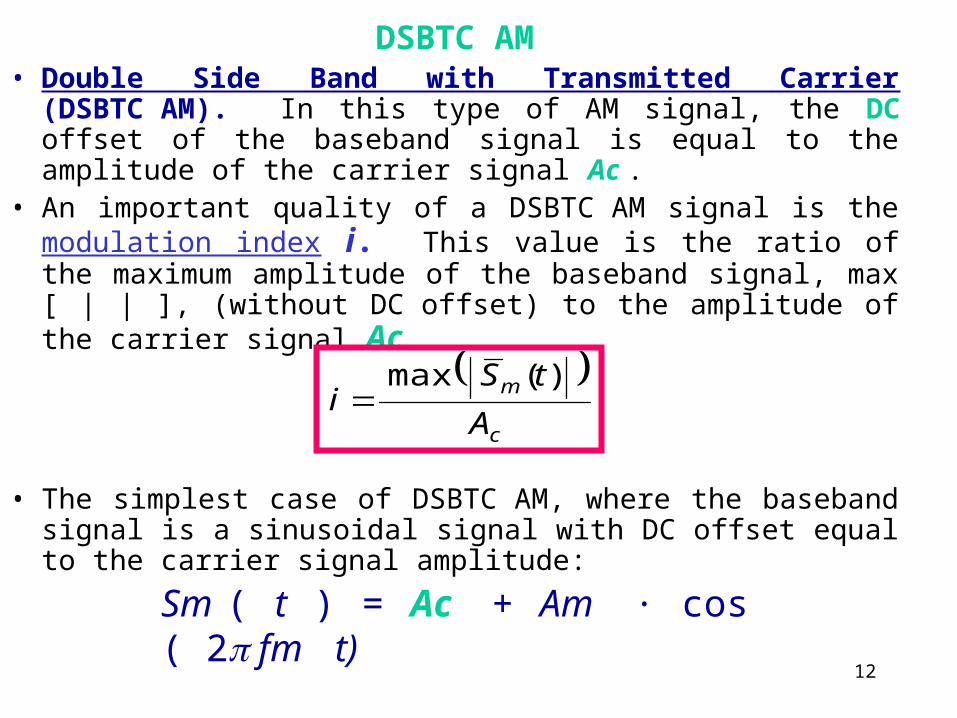
DSBTC AM• Double Side Band with Transmitted Carrier (DSBTC AM). In
this type of AM signal, the DC offset of the baseband signal is equal to the amplitude of the carrier signal Ac .
• An important quality of a DSBTC AM signal is the modulation index i. This value is the ratio of the maximum amplitude of the baseband signal, max [ | | ], (without DC offset) to the amplitude of the carrier signal Ac .
• The simplest case of DSBTC AM, where the baseband signal is a sinusoidal signal with DC offset equal to the carrier signal amplitude:
c
m
A
tSi
)(max
Sm ( t ) = Ac + Am · cos ( 2 fm t)

13
)2(cos)2(cos1)( 1 tftfA
AAAtS cm
c
mcck
c
m
A
Ai
)2(cos)2(cos1)(2
tftfik
AtS cm
c
)(cos)(cos2
1)(cos)(cos yxyxyx
componentfrequencycarrierNoncomponentfrequencyCarrier
tfftffik
Atf
k
A
tftfik
Atf
k
A
tftfik
AtS
mcmcc
cc
cmc
cc
cmc
))(2cos())(2cos(2
1)2cos(
)2cos()2cos()2cos(
)2(cos)2(cos1)(
22
22
2
14
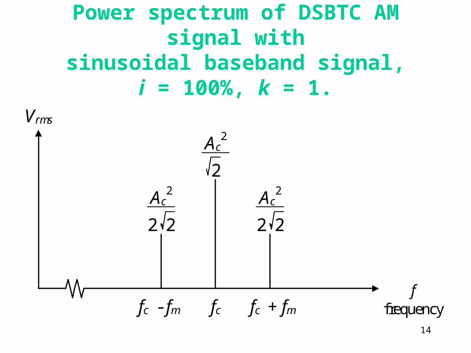
Power spectrum of DSBTC AM signal with
sinusoidal baseband signal, i = 100%, k = 1.
Vrms
ffrequencyfc + fmfc - fm
2
fc
Ac2
2· 2
Ac2
Ac2
2· 2

15
Sm (t)
t
t
Sc (t)
t
S(t)
Ac

16
S50% (t)
t
t
S100% (t)
t
S150% (t)
i = 50%
i = 100%
i = 150%

17
)2(cos)2(cos)( tftfAAtS cmcc
))(2cos())(2cos(2
1)2(cos)2(cos)(
2
2
tfftffA
tftfAtS
mcmcc
cmc
Vrms
ffrequencyfc + fmfc - fm fc
Ac2
2· 2
Ac2
2· 2
Sm ( t ) = Ac · cos ( 2 fm t)
DSBSC AM

18
Sm (t)
t
t
Sc (t)
t
S(t)

19
Amplitude Modulation of Digital Signals
Baseband Signal
Baseband Signal with DC shift
tftftftS mmmm
10cos
5
16cos
3
12cos
4V5)(
tftS cc 2cosV5)( Carrier Signal
tftftftS mmmm
10cos
5
16cos
3
12cos
4V5V5)(

20
Transmitted Signal
sidebandupper
tfftfftffk
V
sidebandlower
tfftfftffk
V
frequencycarrier
tfk
VtS
mcmcmc
mcmcmc
c
...52cos5
132cos
3
12cos
92.15
...52cos5
132cos
3
12cos
92.15
)2cos(25
)(
2
2
2

21
DSBTC AM signal with square wave baseband signal, i = 10
0%, k = 10.
Vrms
ffrequencyfc - fm
2
fc
2.50V
fc - 3fm
2
1.59V
2
1.59V
fc + 3fmfc + fm
2
0.53V
2
0.53V
2
0.32V
2
0.32V
fc - 5fm fc + 5fm

22
Sm (t)
t
t
Sc (t)
t
S(t)
5V

23
DSBSC AM
tftftftS mmmm
10cos
5
16cos
3
12cos
4V5)(
sidebandupper
tfftfftffk
V
sidebandlower
tfftfftffk
VtS
mcmcmc
mcmcmc
...52cos5
132cos
3
12cos
92.15
...52cos5
132cos
3
12cos
92.15)(
2
2
Vrms
ffrequencyfc - fm fcfc - 3fm
2
1.59V
2
1.59V
fc + 3fmfc + fm
2
0.53V
2
0.53V
2
0.32V
2
0.32V
fc - 5fm fc + 5fm
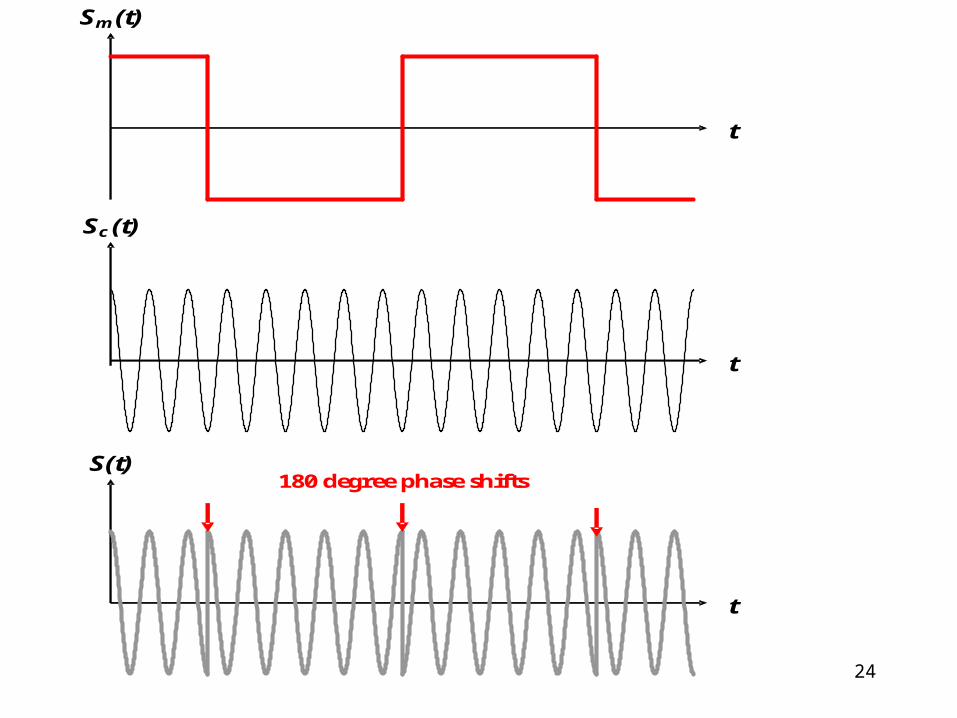
24
t
Sm (t)
t
Sc (t)
t
S(t) 180 degree phase shifts

25
Binary Phase Shift Keying and Quadrature Phase Shift Keying
V5)(if180
V5)(if0)(
)(2cosV25
)(
tS
tSt
ttfk
tS
m
m
c
Since the phase of the transmitted signal can take one of two values (phase jumping), this type of modulation is called binary phase-shift keying (BPSK). It is a constant-amplitude method of modulation.

26
If we add together two BPSK signals that are offset by a 90 degree phase shift, there are four possible phase jumping during every sampling period. Instead of one possible shift of 180º, there are three possible transitions: +90º, 180º, and ‑90º (+270º). The signal can be represented by the following formula:
V5)(V,5)(if315
V5)(V,5)(if225
V5)(V,5)(if135
V5)(V,5)(if45
)(
)(2cosV25
)(
21
21
21
21
tStS
tStS
tStS
tStS
t
ttfk
tS
mm
mm
mm
mm
c

27
t
S(t) phase shifts
t
S1 (t)
t
S2 (t)
0 1 0 1 0
0 1 1 0 0
00 11 01 10 00
180º 90º 180º -90º
Time domain representation of QPSK signal, created by combining BPSK signals S1 and S2 .

28
Reducing Power and Bandwidth of AM Signals
• In DSBTC AM, the carrier frequency component carries no information.
In all forms of amplitude modulation, the two sidebands contain identical information.
• Eliminating one of the two sidebands. • There are therefore four possibilities for transmitting an amplitude
modulated signal • A. Dual sideband, transmitted carrier (DSBTC AM)• B. Vestigial sideband• C. Dual sideband, suppressed carrier (DSBSC AM)• D. Single sidebandSelecting the type of transmission can depend on the following
factors:• Power limitations• Bandwidth limitations• Simplicity of Demodulation Equipment

29
• The power required for transmitting a sinusoidal baseband signal with DSBTC AM is:
Pt : Total transmitted power, Ac :Carrier Signal Amplitude
• i : Modulation index
• For a modulation index of 100%, the transmitted power will be 1.5 times the power squared of the carrier frequency. Each sideband contributes 0.25 times the power of the carrier frequency.
• Vestigial sideband uses only one of the two sidebands of the signal, and also reduces the amplitude and power of the carrier signal.
21
222
12
22
1
22
222
iP
AAAP
c
cmct

30
Four possible ways to transmit an AM signal.
fc
Vrms
(a) DSBTC AM
ffc
Vrms
(c) DSBSC AM
f
fc
Gain
ffc
Vrms
f
Bandpass Filter
fc
Vrms
(b) Vestigial sideband AM
ffc
Vrms
(d) Single sideband AM
f
Bandpass Filter

31
Frequency Modulation
• Additive noise
• Frequency modulation is actually a special case of phase modulation, where the phase of the transmitted signal accumulates according to the amplitude of the baseband signal:
k : Constructional coefficient of the modulator
t
mcc dSktfAtS )(2cos)(

32
• To find the maximum possible frequency deviation of an FM signal, we can assume the baseband signal is a constant voltage of +Am , then the integral will reduce to a linear function of t :
tAk
fAtAktfAtS mccmcc
2
2cos2cos)(
2max
mc
Akf
Sm ( t ) = Am · sin (2 fm )
)2(cos2
)2(sin)()(0
tff
AkdfAkdSkt m
m
mt
mm
t
m
m
mf f
Akk
2
)2(cos2cos)( tfktfAtS mfcc
33
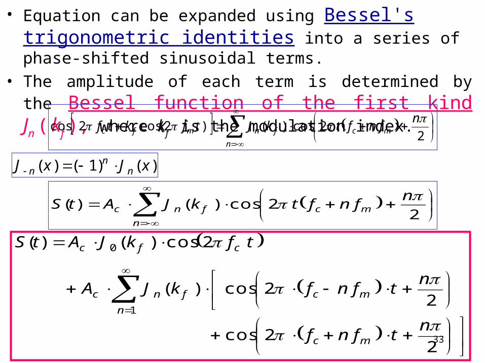
• Equation can be expanded using Bessel's trigonometric identities into a series of phase-shifted sinusoidal terms.
• The amplitude of each term is determined by the Bessel function of the first kind Jn ( kf ), where kf is the modulation index.
n
mcfnmfcn
fnftkJtfktf2
2cos)()2(cos2cos
n
mcfncn
fnftkJAtS2
2cos)()(
)()1()( xJxJ nn
n
22cos
22cos)(
2cos)()(
1
0
ntfnf
ntfnfkJA
tfkJAtS
mc
n
mcfnc
cfc

34
Power and Bandwidth of FM Signals
• Calculating the power of an FM signal is much simpler in the time domain.
1
220
22
)(2)(2
1
2 fnfcc
FM kjkjAA
P
12 fT kBB
In this equation B is effective bandwidth of baseband signal, but BT is absolute bandwidth of FM signal

35
Ac · cos ( 2 fc + kf cos ( 2 fm ) ) at various values of kf . Vrms
f
kf = 0.5
Vrms
f
kf = 1
Vrms
f
kf = 2
Vrms
ffc +6fm
kf = 10
fc +9fm fc -9fm fc -6fm
fc fc + 3fm fc - 3fm
fc fc + 3fm fc - 3fm
fc fc + 3fm fc - 3fm
fc fc +3fm fc -3fm
36
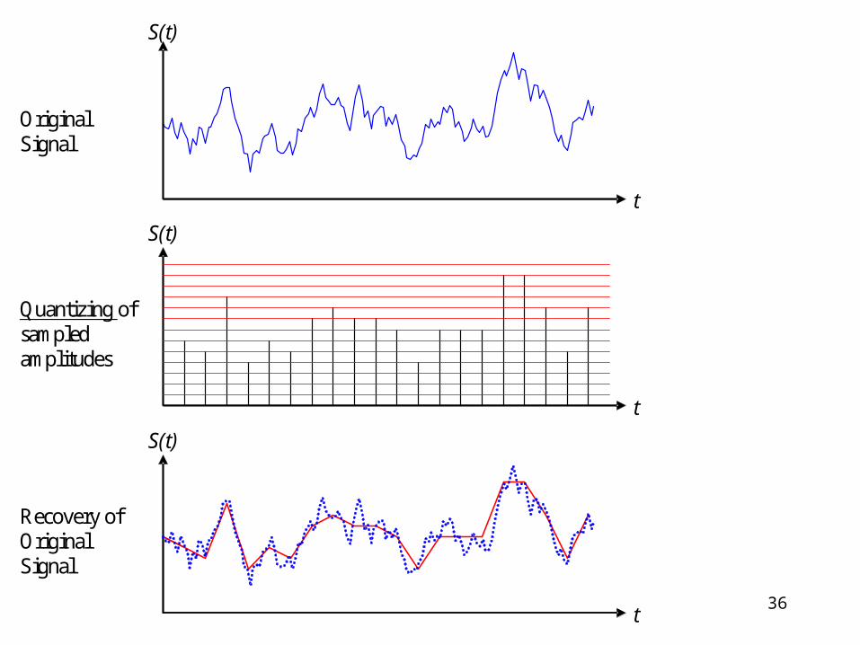
Original Signal
Quantizing of sampled amplitudes
S(t)
S(t)
t
t
Recovery of Original Signal
S(t)
t

37
• For instance, we want to use only 8 bits to store each sample, and the maximum possible value of the analog signal is 10, then we can quantize the signal into multiples of 10/256 (0.03906). Each number will be represented as an 8-bit binary number between 0 and 255. To approximately reconstruct the original analog signal, each 8-bit sample must be multiplied by 0.03906.
• When sending a digital signal over a transmission line, the sampling rate of the signal determines the bandwidth required for successful transmission.
• Level detection and regeneration of a digital signal allows the signal to be transmitted with a significantly smaller bandwidth than the absolute bandwidth of the signal.

38
• The Nyquist criterion determines the sampling rate necessary to capture all the information of an analog signal with a discrete sequence (taken by sampling the signal at a certain rate).
• “The signal must be sampled at a rate of twice the signal bandwidth
s > 2B
• (s is the sampling frequency, B is bandwidth of analog signal’s.):
39
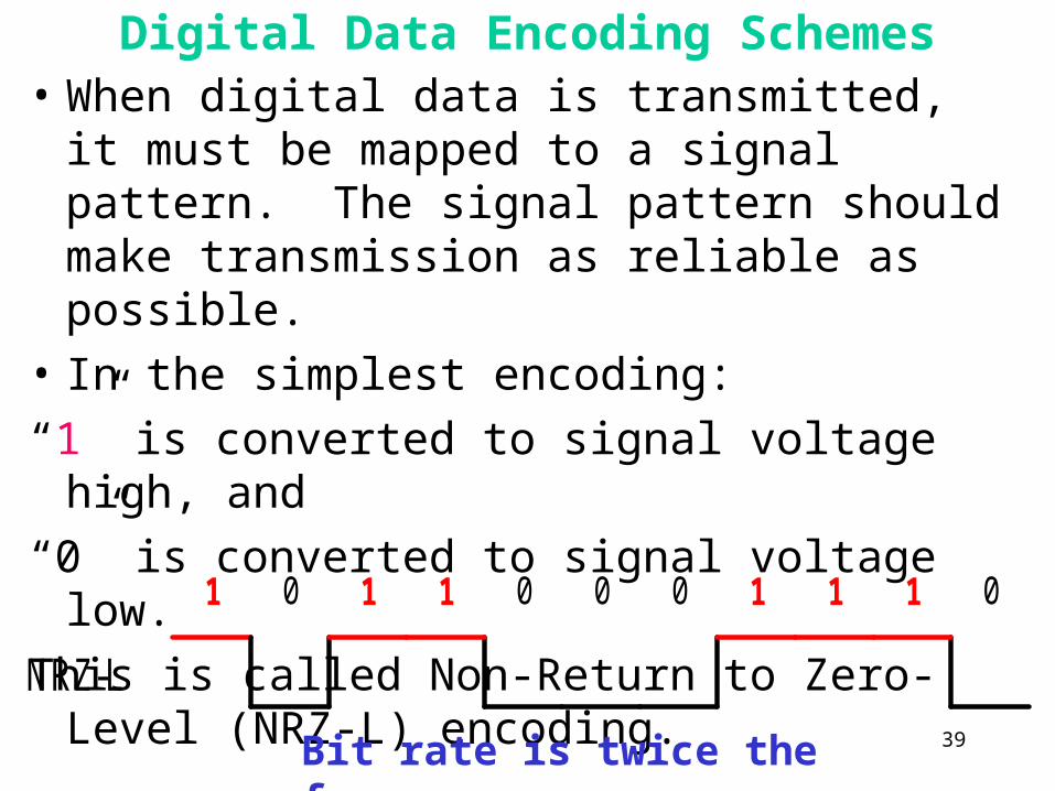
Digital Data Encoding Schemes• When digital data is transmitted, it must be
mapped to a signal pattern. The signal pattern should make transmission as reliable as possible.
• In the simplest encoding:
“1” is converted to signal voltage high, and
“0” is converted to signal voltage low.
This is called Non-Return to Zero-Level (NRZ-L) encoding.
1 1 1 0 0
NRZ-L
0 1 1 0 1 0
Bit rate is twice the frequency

40
• Manchester Encoding, or Biphasic-Level:
0:Signal low (first half) / Signal high (second half)
1:Signal high (first half) / Signal low (second half)
1 1 1 0 0
Manchester
0 1 1 0 1 0
Bit rate = signal frequency