
Siemens Digital Industries Software Closing the loop on ...
16
Executive summary Over the last 30 years the use of fiber-reinforced plastic (FRP) composites has grown due to their lightweight properties and structural performance. Still, there are significant manufacturing challenges that need to be surmounted to achieve mass production and automation. Predicting structural performance remains an important step in the virtual design process, but the final product has a high level of uncertainty due to the lack of control of the manufacturing process and its effects on the structure. Consequently, manufacturing with composites is often costly and time-consuming, involving significant trial-and-error. However, by virtually mastering the composites manufacturing process and taking its impact into account in the design, users can optimize product performance. Siemens Digital Industries Software siemens.com/plm Closing the loop on composites Using the digital twin to virtually predict and optimize product performance
Transcript of Siemens Digital Industries Software Closing the loop on ...

Executive summary Over the last 30 years the use of fiber-reinforced plastic (FRP) composites has grown due to their lightweight properties and structural performance. Still, there are significant manufacturing challenges that need to be surmounted to achieve mass production and automation. Predicting structural performance remains an important step in the virtual design process, but the final product has a high level of uncertainty due to the lack of control of the manufacturing process and its effects on the structure. Consequently, manufacturing with composites is often costly and time-consuming, involving significant trial-and-error. However, by virtually mastering the composites manufacturing process and taking its impact into account in the design, users can optimize product performance.
Siemens Digital Industries Software
siemens.com/plm
Closing the loop on compositesUsing the digital twin to virtually predict and optimize product performance

White paper | Closing the loop on composites
2Siemens Digital Industries Software
Contents
Abstract ................................................................... 3
Harnessing the potential of composites .................. 4
Manufacturing challenges ....................................... 6Composites manufacturing simulation ........................ 6Draping simulation in Fibersim ................................... 7Simulating infusion in Simcenter STAR-CCM+ .............. 9Curing simulation in Simcenter 3D ........................... 10First-time-right design enables virtual mold compensation ...................................... 11Closing the loop between as-designed and as-manufactured composites ............................. 12Conclusion ............................................................. 15Acknowledgements ................................................. 15References .............................................................. 15

White paper | Closing the loop on composites
3Siemens Digital Industries Software
Abstract
Developing composite products is a unique process because form always follows function. Therefore, it is no surprise that virtually simulating the design and physical performance of composites has been essential to its growing use. Siemens Digital Industries Software has offered simulation tools for draping, infusion and curing modeling for many years, allowing the user to predict and virtually optimize a composite product’s per-formance. Closing the loop between as-designed and as-manufactured composites allows you to incorporate the manufacturing process effects in the design cycle, delivering product performance for the given manufac-turing process and yielding an important return-on-investment (ROI).

White paper | Closing the loop on composites
4Siemens Digital Industries Software
Harnessing the potential of composites
Composites are promising materials because they are lightweight and enhance structural performance, although manufacturing with them poses challenges and predicting their structural performance is not yet straightforward.
As an example, 50 percent of the companies in aero-space and defense industries interrogated in a report published by Tech Clarity in 20161 acknowledged they encountered issues due to springback distortion after curing. That percentage increased to 70 percent when curved panels were involved, and in 20 percent of those cases it led to components being out of tolerance. Most of these manufactures take the easiest and fastest approach to correct the case (with tool compensation) instead of redesigning or adjusting the manufacturing process. The questionnaire1 also identified many top performers based on targets such as design due dates, cost targets, product development budget and cycle time. By using specific design guidelines, respondents said they were able to mitigate their product develop-ment risks (for example, scrapped parts) by 48 percent,
which allowed them to improve their design process. They also indicated if they have better information upfront regarding the manufacturing process, the cor-responding errors can be significantly reduced. Springback is still a considerable source of excess cost and waste.
Manufacturing composites is often a cumbersome trial-and-error process in which designers learn by doing and by designing variant after variant. Benefits can be achieved by virtually simulating the composites manu-facturing process so designers can optimize and better understand the design process and create correspond-ing optimal tooling for the specific process and applica-tion. For a thermoset composite material, this includes draping simulations; for example, simulating the manu-facturing step in which the reinforcement is wrapped onto a mold, infusion modeling to predict the resin flow during the composites impregnation process, and cur-ing to predict the densification of the composites matrix under thermal treatment (see figure 1).
Figure 1: Typical thermoset composite manufacturing steps enabled by simulations: drape, flow, cure.
Flow
Drape Cure
White paper | Closing the loop on composites
5Siemens Digital Industries Software
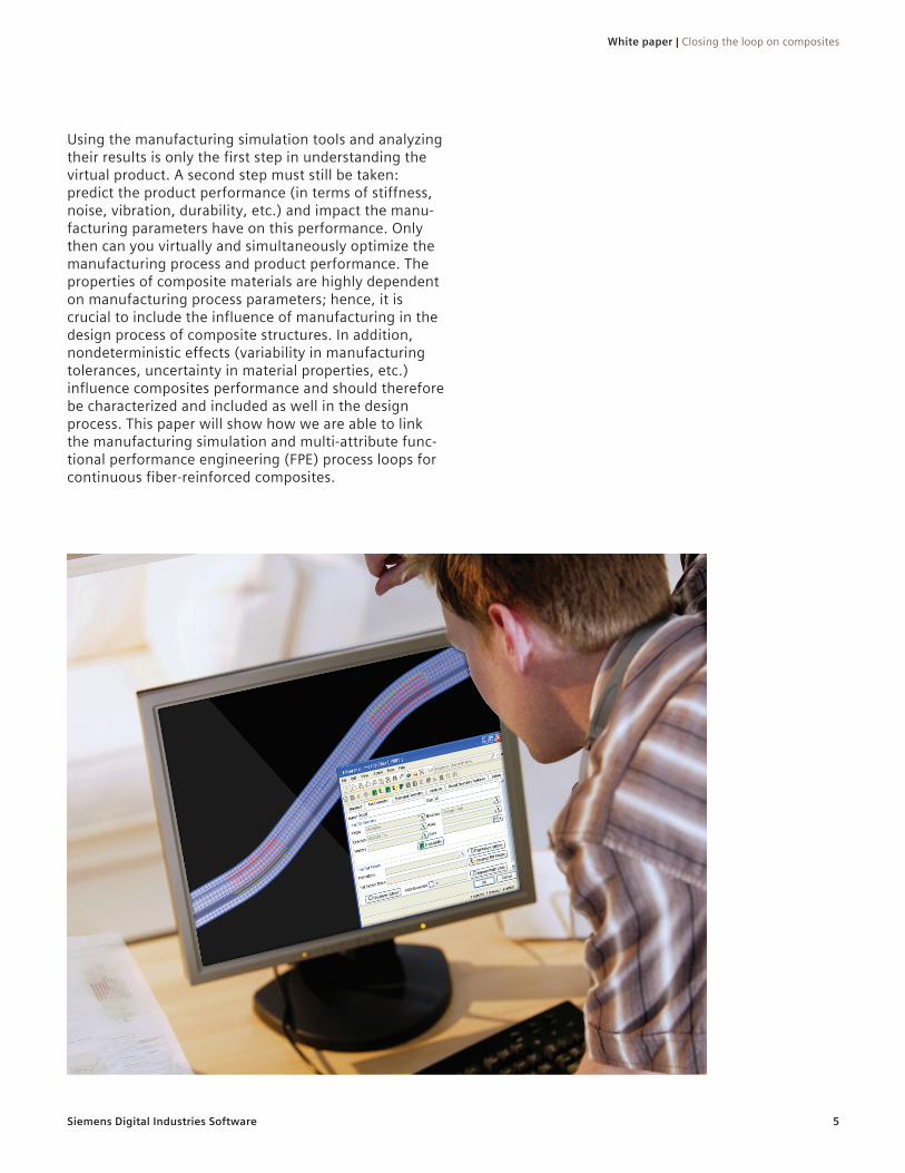
Using the manufacturing simulation tools and analyzing their results is only the first step in understanding the virtual product. A second step must still be taken: predict the product performance (in terms of stiffness, noise, vibration, durability, etc.) and impact the manu-facturing parameters have on this performance. Only then can you virtually and simultaneously optimize the manufacturing process and product performance. The properties of composite materials are highly dependent on manufacturing process parameters; hence, it is crucial to include the influence of manufacturing in the design process of composite structures. In addition, nondeterministic effects (variability in manufacturing tolerances, uncertainty in material properties, etc.) influence composites performance and should therefore be characterized and included as well in the design process. This paper will show how we are able to link the manufacturing simulation and multi-attribute func-tional performance engineering (FPE) process loops for continuous fiber-reinforced composites.

White paper | Closing the loop on composites
6Siemens Digital Industries Software
Challenges remain in the manufacturing process. In the two figures below, the influence of the manufacturing process is visualized in a top-down view of an omega (Ω) profile of thermoplastic composite sheets that have been stamped. In figure 2 (left) we see the weft and warp fiber orientations are nicely perpendicular to one another. In figure 2 (right), however, asymmetric forces with asymmetric boundary conditions cause a deforma-tion of the product, so the fibers are no longer perpen-dicular. The resulting composite part has significantly greater shear deformation, which affects the part’s structural performance.
Moreover, in most composites manufacturing the matrix undergoes a phase transformation from a liquid to a solid state. This transformation causes the material to generate residual stresses, which in turn causes the composite structure to emerge in a deformed state (for
example, not as-designed) after manufacturing. During assembly, the manufacturer forces the composite com-ponent into the desired as-designed shape by mechani-cally fixing the component to a base structure, which puts a preload on the structure and hence affects the structural performance.
Composites manufacturing simulation To overcome manufacturing challenges, the next step in the virtual simulation of composites parts is to simu-late the manufacturing process to predict, and therefore compensate, for any deformation due to this process. For a thermoset composite structure, this includes draping, infusion and curing simulations to virtually master the manufacturing process and assess the impact on the product structure.
Manufacturing challenges
Figure 2: Proper fiber orientation (left), skewed fiber orientation (right).

White paper | Closing the loop on composites
7Siemens Digital Industries Software
Draping simulation in FibersimDraping refers to wrapping the reinforcement onto a mold. The main influence of draping is reorienting fibers and some bending. When draping over a double curved mold, the reinforcement tends to adapt by in-plane shear. This causes a reorientation of the fibers.
In the state of the art, there exist two approaches for draping simulations:
• The kinematic approach: This is an approximate approach that allows predicting the in-plane shear and bending (there is no stretching and no forces are calculated). The Fibersim™ portfolio from Siemens can be used to simulate the laminate composite layup by accounting for draping and avoiding manufacturing-induced defects, such as wrinkling, by introducing darts or splits in the blank
• The mechanical approach: A complex constitutive model is built, including exact boundary conditions for shear forces/shear angles predictions.
A disadvantage of this approach is that you must per-form an extensive material characterization routine, including picture frame or bias extension, bending characterization, uniaxial or biaxial tensile test and even friction characterization, to get all the param-eters you need, which is a difficult process step. With the kinematic approach, the material is allowed only to distort in the shear direction, while the bending resistance is considered negligible. Hence, no exten-sive material characterization routines are required
Although the central processing unit (CPU) time depends on the available computational power, in general the kinematic approach, as in the case of Fibersim, takes on the order of seconds, while the mechanical approach often takes hours or even days. Hence, despite not considering the full constitutive behavior of the material, the kinematic approach opens the possibility of rapidly assessing the influence of layup configuration and draping strategy on the performance of a composite component.
Figure 3: Example of the effect of draping on the fiber orientation.
Initial configuration
Draping
In-plane shear
Figure 4: Draping simulations – two state-of-the-art approaches.
Siemens’ Fibersim software uses the kinematic approach.
Other specialized software are developed for draping simulations using the mechanical approach.
Kinematic approach Mechanical approach

White paper | Closing the loop on composites
8Siemens Digital Industries Software
Figure 5 shows an example of the importance of using Fibersim to drape a component with a non-crimp fabric (NCF) and to import the local fiber orientations in the structural analysis calculation. Whereas the first mode (left, top) depends mainly on geometry and density, the ninth mode (right, top) is more dependent on draping (one can distinguish local deformations that depend on the fiber orientation). Hence, its behavior is better predicted with a draping simulation (blue curve) than
without draping (red curve) versus test (black). The frequency response function (FRF) with draping doesn’t perfectly match the test results, as a lot of other aspects, such as local variations in thickness and the fiber volume fraction (Vf), are needed to obtain a good correlation with the real product performance. Current draping simulation software packages still do not con-sider these aspects (for example, compressibility).
Figure 5: Whereas the first mode (left, top) depends mainly on geometry and density, the ninth mode (right, top) is more dependent on draping (many deformations that depend on fiber orientation). Hence, it is better predicted with a draping simulation (blue curve) than without draping (red curve) versus test results (black).
Mode 1 (~100Hz) Mode 9 (~750Hz)
with drapingwithout drapingtest results

White paper | Closing the loop on composites
9Siemens Digital Industries Software
Simulating infusion in Simcenter STAR-CCM+Infusion is the act of forcing the uncured resin through the dry reinforcement to obtain a completely impreg-nated composite with minimal void content. During infusion, the dry and draped reinforcement is gradually impregnated with the uncured resin. The main goal is to obtain a fully impregnated structure. During the infu-sion, defects such as dry spots and voids can occur. Components with dry spots are scrapped, while exces-sive void content has an influence on the product per-formance. Therefore, the void content should be as low as possible (target is 1 to 2 percent volume). Simulation-based predictions of the infusion process raise awareness of where such defects can occur and reduce defects by improving the manufacturing process.
Two approaches exist for infusion simulations (see figure 6):
• The general computational fluid dynamics (CFD) solver approach in Simcenter™ STAR-CCM+™ software: solving the Navier-Stokes equation. This assumes the fluid is incompressible and preserves a lot of the physics of the flow in the solution sequence, so physical phenomena can be predicted more accurately
• The CFD solver approach for Darcy’s law in other prod-ucts: This approach comes with many assumptions (assume steady flow, low Reynolds number, Stokes flow and no external body forces). Although this can provide decent results in some cases, the assumptions make the results inaccurate for typical cases that can occur with infusion; for example, race-tracking (explained below)
Figure 6: There are two approaches to infusion simulation: the general CFD solver (left) and the approximate CFD solver for Darcy’s law (right).
Simcenter STAR-CCM+ is a general CFD solver based on Navier-Stokes.
Other specialized software are developed for composite infusion simulations according to Darcy’s law.
General CFD-solver CFD solver for Darcy’s law

White paper | Closing the loop on composites
10Siemens Digital Industries Software
Using Simcenter STAR-CCM+ enables you to solve the Navier-Stokes equation. This allows the user to solve areas where no reinforcement is present (race-track-ing); the drawback is the higher CPU cost. Race-tracking occurs when there is clearance between the reinforce-ment and the mold. The resin will choose the path of least resistance and flow rapidly along the clearance.
Curing simulation in Simcenter 3D Curing is a thermochemical activity that gives rise to the densification of the matrix that affects (a) local material strength/stiffness and (b) local stress state (residual state). With Simcenter 3D and Simcenter Samcef® soft-ware8, curing predictions (thermal and mechanical) can be performed to compute the distortion and take into account the temperature variation across the part and the corresponding cure cycle. Linking the result from this simulation to Simcenter 3D facilitates updating the initial mold geometry and manufacturing an as-designed com-posite component4.
Material properties needed for the curing analysis are the parameters related to the cure kinetic behavior, which is measured by digital scanning calorimetry (DSC) and the thermal/physical properties (conductivity, heat capacity and density). The degree of cure can be described by many different models, but general similarities exist. One of the most commonly used models currently is by Sourour and Kamal5.
Since during manufacturing the reinforcement is not allowed at the same dimensions as the mold geometry, it is important to be able to assess this influence on the flow profile. Figure 7 shows the race-tracking phenom-enon experimentally on the photos, and it shows Simcenter STAR-CCM+ can be used to accurately predict experimental results1.
Figure 7: Experimental example without race-tracking (left) and with race-tracking (middle). The figure on the right shows Simcenter STAR-CCM+ can be used to accurately predict race-tracking (line fronts) as compared to test results (the series of dots).
Race-trackingNo race-tracking
(Condition A)Outlet
side
Laminated NCFSpace Space
Injection direction
Clearance 2mmInlet
side
(Condition B)
700 mm
300 mm
Figure 8: The full tidal blade: upper half (left) and lower half (middle), with tapering by ply drops (right).
Lower halfLower half Tapering by ply drops
Eq. 1: dαdt=k1+k2m1-αn
where m and n are reaction orders and ki are reaction rates that are described by the Arrhenius relation:
Eq. 2: ki=Aiexp-EiRT
with Ai a rate constant, Ei activation energy and T as temperature.
As an example, a full tidal blade was developed using Simcenter 3D (with the Simcenter Samcef solver)7 in the framework of the “Enabling Next Generation COmposite Manufacturing” by In situ Structural Evaluation and Process Adjustment (ECOMISE) research and development (R&D) project funded by the European Commission. The tidal blade is 1.5-meters (m) long with a root diameter of 0.3m made using carbon fiber and epoxy. Simcenter 3D Laminate Composites was used to create the CAD geometry and per-form draping using the native kinematic draping capabilities of Fibersim, yielding a detailed layup definition. A 3D finite element (FE) mesh was created by layup inflation and consid-ering the different drop off. See figure 8.

White paper | Closing the loop on composites
11Siemens Digital Industries Software
First-time-right design enables virtual mold compensationBy using Siemens Digital Industries Software solutions, you can assess the manufacturing steps that make up the composite process chain as shown in figure 10. This not only enables you to optimize each step individually, but by linking process steps you can consider their effect on the global manufacturing chain.
Moreover, linking these solutions allows you to virtually optimize the process and get the desired part shape without having to go through a time-consuming and
costly trial-and-error approach. Partnering with OmniCAD gives Siemens the flexibility to adjust the mold geometry by considering the distortion after demolding the component. This involves manipulating complex surfaces, while maintaining critical product characteristics. OmniCAD accomplishes these time-con-suming tasks in an automated manner. Hence, the user can perform mold compensation based on virtual analy-sis. This enables end users to avoid manufacturing a new mold or altering the existing one after finding the properties of the manufactured structure in real life.
Figure 9: Shown are the results of the parametric study on the curing simulation of the tidal blade. By increasing the convection term, it lowers the temperature of the mold and inside the blade, while preserving a high degree of cure.
Temperature of the mold Temperature inside the blade
Degree of cure of the blade Blade outer surface (mold side)
Figure 10. Siemens solutions that address the full chain of thermoset composite manufac-turing steps.
NX FibersimSimcenter
STAR-CCM+
OmniCAD
Simcenter 3D Simcenter 3D
The simulation of curing at 100 degrees Celsius (°C) indicated the temperature inside the blade went up to 165°C (internal face at root), which resulted in the thermal degradation of the resin. Moreover, the tem-perature of the mold went up to 142°C, which can create a dangerous working environment [4]. This is the result of the thickness of the tidal blade, but it is good this can be identified based on virtual simulations.
After a parametric study of (a) the mold thickness and (b) the convection term, it was shown that increasing the convection from 50 to 250 Watt/meter2 Kelvin should result in a lower temperature inside the blade and lower peak temperature of the mold. This result [4] is shown in figure 9.

White paper | Closing the loop on composites
12Siemens Digital Industries Software
Closing the loop between as-designed and as-manufactured compositesIn this section, results are presented for a combined virtual and experimental study taken from the Flemish government agency Flanders Innovation & Entrepreneurship (VLAIO)/Flanders Make project VIDESPRO, in which the aim was to link the manufactur-ing simulation and the multi-attribute FPE process loops for continuous fiber-reinforced composites. In this project, a newly extended process was achieved so you can fine-tune the manufacturing process parameters to optimize the multi-attribute functional performance targets (stiffness, strength, impact, durability, noise and vibration). See figure 10. In practice, we assessed the influence of fiber reorientation, simulation input param-eters and some uncertainty defined on certain material parameters. Results of industrial relevance are pre-sented on an omega profile inspired by the automotive industry. By achieving this closed-loop process, we can produce a more reliable digital twin that can support broader deployment of composites in industry, reducing safety concerns and weight, and replacing overly con-servative design practices with more realistic ones.
By using Fibersim, the fiber orientation that results after forming an omega-shaped component can be as-sessed. One of the key input parameters is the location of the rosette point; for example, the starting point of the draping simulation. Using process integration and design optimization tools (such as HEEDS™ software, which is available as part of the Simcenter portfolio), it is possible to parametrize the location of the rosette point and assess its influence on (a) the local fiber orientation and (b) the predicted performance. In this study the noise, vibration and harshness (NVH) per-formance of the part was predicted using Simcenter Nastran® software solution (Sol) 103 (modal analysis). The predicted fiber orientations from Fibersim can be imported using the Simcenter 3D native laminate com-posites solutions. The result of the variation in rosette point and the comparison with the experimentally mea-sured result can be seen in figure 12.
Figure 12: Influence of the variation of the rosette point on the FRF of a thermoset composite omega-shaped stiffener.
Although some variation in the FRF response was noticed, the influence of the location of the rosette point seems rather small.
Figure 11: Chaining forming and curing: closing the loop between as-designed and as-manufactured composites products.
Chaining forming and curing
Local fiber orientations
Cure/residual stress
Experimental testing
NVH
Vaccum assisted resin infusion
Thermoforming
Correlation/updating

White paper | Closing the loop on composites
13Siemens Digital Industries Software
Additionally, the influence of the local thickness was investigated, since during experimental measurements it was noticed the thickness of the component is not constant. This is shown in figure 13 (a).
This thickness variation is introduced into the numerical model by defining two zones with a different thickness. One zone has a thickness of approximately 1.7 millime-ters (mm), represented by the vast blue area, while the
orange area represented by the higher thickness area of the measured component and is assigned a thickness of either 2.5mm or 3mm. The influence on the FRF can be seen in figure 14, where it can be noticed that although only a relatively small area had a different thickness, the resulting FRF was significantly affected throughout the frequency spectrum.
To indicate the versatility and accuracy of the presented workflow, an additional material and process technology has been selected. The same omega-shaped component is made using thermoforming of a thermoplastic woven
reinforcement as indicated in the upper right corner of figure 11. This stiffener was also subjected to NVH mea-surements and the FRF has been experimentally deter-mined. Fibersim is used to drape the component with a woven reinforcement (the rosette has been chosen in the middle top central region of the stiffener). The influ-ence of the in-plane shear (see figure 3) on the local material properties is considered since when the warp and weft yarns shear relative to each other, the material
behaves in an orthotropic way, while if there is no shear the material is often considered transversely orthotropic. Simcenter 3D uses the improved woven model to calcu-late the equivalent ply orthotropic properties. The plies that exhibit nonorthogonal yarn angles can be defined using Simcenter 3D7 and will do the following: • Compute the equivalent orthotropic material properties
for plies with nonorthogonal yarn angles • Apply the computed orthotropic elastic constants, ther-
mal expansion coefficients and thermal conductivity• Consider the shear in the failure metric computation
Figure 13: Local thickness profile of the omega-shaped stiffener (a) as measured and (b) simplified within Simcenter 3D by defining two zones with different thickness.
A B
Figure 14: FRF obtained with the two-zone model with variable thickness (red = 2.5mm and green = 3mm) compared to the test result and the constant thickness (1.70mm) model.

White paper | Closing the loop on composites
14Siemens Digital Industries Software
With the improved woven model, you can simulate the as-manufactured mechanical properties of weaves that exhibit shear to assess stiffness, stability, thermal conduc-tivity and strength as shown in figure 15. It can be
concluded that by using Fibersim in combination with the woven model capabilities that are native in Simcenter 3D, the NVH behavior of the composite component can be accurately predicted.
Figure 15: The FRF of a woven reinforced thermoplastic composite omega-shaped stiffener compared to the predictions made using Simcenter 3D.

White paper | Closing the loop on composites
15Siemens Digital Industries Software
Composite materials offer solutions to design and pro-duce efficient, lightweight and cost-effective compo-nents. However, it appears the industry can improve many key aspects related to the use of this type of mate-rial. It is expected the increasing use of computer-aided engineering (CAE) will make it possible to more accu-rately predict not only product performance, but more importantly, issues related to the manufacturing of com-posite structures in a tailored user environment. With solutions like Simcenter and Fibersim, Siemens Digital Industries Software has offered simulation tools for drap-ing, infusion and curing modeling for several years. These solutions allow the user to predict and virtually optimize a composite product’s performance and support the notion of a digital twin, meaning the construction of a digital
copy of a real component. It offers to the user an end-to-end process solution and workflow to design composite structures right-the-first-time thanks to increased accu-racy in predicting product performance and the effects of the manufacturing process on the product. By accelerat-ing and virtually treating the manufacturing simulation process and performance prediction process, one can truly close the loop between as-designed and as-manu-factured composites products. In addition, the ability to explore design space and product optimization can lead to components that have maximum cost efficiency and decrease time-to-market.
AcknowledgementsWe gratefully acknowledge Flemish government agency Flanders Innovation & Entrepreneurship (VLAIO) for funding the FlandersMake project “VIDESPRO” (virtual design platform for sheet material products, 2015-2018). We thank Noesis Solutions and University of Calabria (the thesis of Luca Spina) for their collabora-tion and the Sirris Leuven-Gent Composites Application Lab (SLC-Lab) for their support in the manufacturing of the validation cases. We acknowledge the European Commission for funding the FP7-2013-NMP-ICT-FoF R&D project, “Enabling Next Generation COmposite Manufacturing by In-Situ Structural Evaluation and Process Adjustment” (ECOMISE, 2013-2016), and we gratefully acknowledge the SKYWIN Walloon project, “Technologies Avancées pour Pièces Complexes et Intégrées” (TECCOMA), part of Plan Marshall SKYWIN (2015-2019).
References1. Michelle Boucher, “Composites for A&D,” Tech Clarity Inc., 2016.2. A. Long, “Composites Forming Technologies,” Woodhead Publishing,
2007. 3. M. Kobayashi, K. Dan, T. Baba, K. Yamakawa, R. Nakano, “Visualization
experiment and numerical simulation of liquid impregnation with race-tracking for RTM process,” proceedings of ECCM17, 2016.
4. F. Pascon, T. van Eekelen, C. Brauner, M. Bach, “An integrated virtual tool chain for the simulation of thermoset composite manufacturing processes,” SAMPE Europe Conference 2016, Liege (Belgium), September 13-15, 2016.
5. S. Sourour, M. R. Kamal, “Differential scanning calorimetry for characterization of thermoset cure,” SPE Annual Technical Papers, p. 93, 1972.
6. L. Spina, “Numerical assessment of the influence of manufacturing features on the modal behaviour of a composite structure,” MSc thesis, University of Calabria, April 17, 2018.
7. Siemens, Simcenter 3D documentation: https://docs.plm.automation.siemens.com/tdoc/nx/1847/nx_help#uid:xid1484869
Conclusion

Siemens Digital Industries Software
HeadquartersGranite Park One 5800 Granite Parkway Suite 600 Plano, TX 75024 USA +1 972 987 3000
AmericasGranite Park One 5800 Granite Parkway Suite 600 Plano, TX 75024 USA +1 314 264 8499
EuropeStephenson House Sir William Siemens Square Frimley, Camberley Surrey, GU16 8QD +44 (0) 1276 413200
Asia-PacificUnit 901-902, 9/FTower B, Manulife Financial Centre223-231 Wai Yip Street, Kwun TongKowloon, Hong Kong +852 2230 3333
www.sw.siemens.com© 2019 Siemens. A list of relevant Siemens trademarks can be found here. Other trademarks belong to their respective owners.
77493-C9 9/19 A
About Siemens Digital Industries SoftwareSiemens Digital Industries Software is driving transformation to enable a digital enterprise where engineering, manufacturing and electronics design meet tomorrow. Our solutions help companies of all sizes create and leverage digital twins that provide organizations with new insights, opportunities and levels of automation to drive innovation. For more information on Siemens Digital Industries Software products and services, visit www.sw.siemens.com or follow us on LinkedIn, Twitter, Facebook and Instagram. Siemens Digital Industries Software – Where today meets tomorrow.
16