SIAI MARCHETTI SF-260 - vqmodel.com · 4- Aileron servo installation Siai Marchetti SF-260 L/R ......
23
SPECIFICATIONS Wingspan:.........................1630mm (64.1in) Length:..............................1300mm (51.1in) Electric Motor:.....................See next pager Glow Engine:.................... .55 - .61 2T RTF Weight: 3.9Kg / 8.6lbs (Will vary with Equipment Used). Radio:......................8 Channel / 6-7 Servos Function: Ailerons-Elevator-Rudder-Throttle Flaps-Optional Retractable Landing Gear. WARNING! This radio controlled model is NOT a toy. If modified or flown carelessly it could go out of controll and cause serious human injury or property damage. Before flying your airplane, ensure the air field is spacious enough. Always fly it outdoors in safe areas and seek professional advice if you are unexperienced. ACHTUNG! Dieses ferngesteuerte Modell ist KEIN Spielzeug! Es ist für fortgeschrittene Modellflugpiloten bestimmt, die ausreichende Erfahrung im Umgang mit derartigen Modellen besitzen. Bei unsachgemässer Verwendung kann hoher Personen- und/oder Sachschaden entstehen. Fragen Sie in einem Modellbauverein in Ihrer Nähe um professionelle Unterstätzung, wenn Sie Hilfe im Bau und Betrieb benötigen. Der Zusammenbau dieses Modells ist durch die vielen Abbildungen selbsterklärend und ist für fortgeschrittene, erfahrene Modellbauer bestimmt. Radio control model / Flugmodel ALL BALSA, PLYWOOD CONSTRUCTION AND ALMOST READY TO FLY SIAI MARCHETTI Instruction manual / Montageanleitung TECHNISCHE DATEN Spannweite:...................................1630mm Lange:............................................1300mm Elektroantrieb.............(siehe nächste Seite) Verbrennerantrieb:...............................10cc Fluggewicht:.......................................3.9Kg Fernsteuerung.............8 Kanal / 6-7 Servos VQ No: VQA143GE - VQA143US - VQA143IT SF-260 EP GP
Transcript of SIAI MARCHETTI SF-260 - vqmodel.com · 4- Aileron servo installation Siai Marchetti SF-260 L/R ......
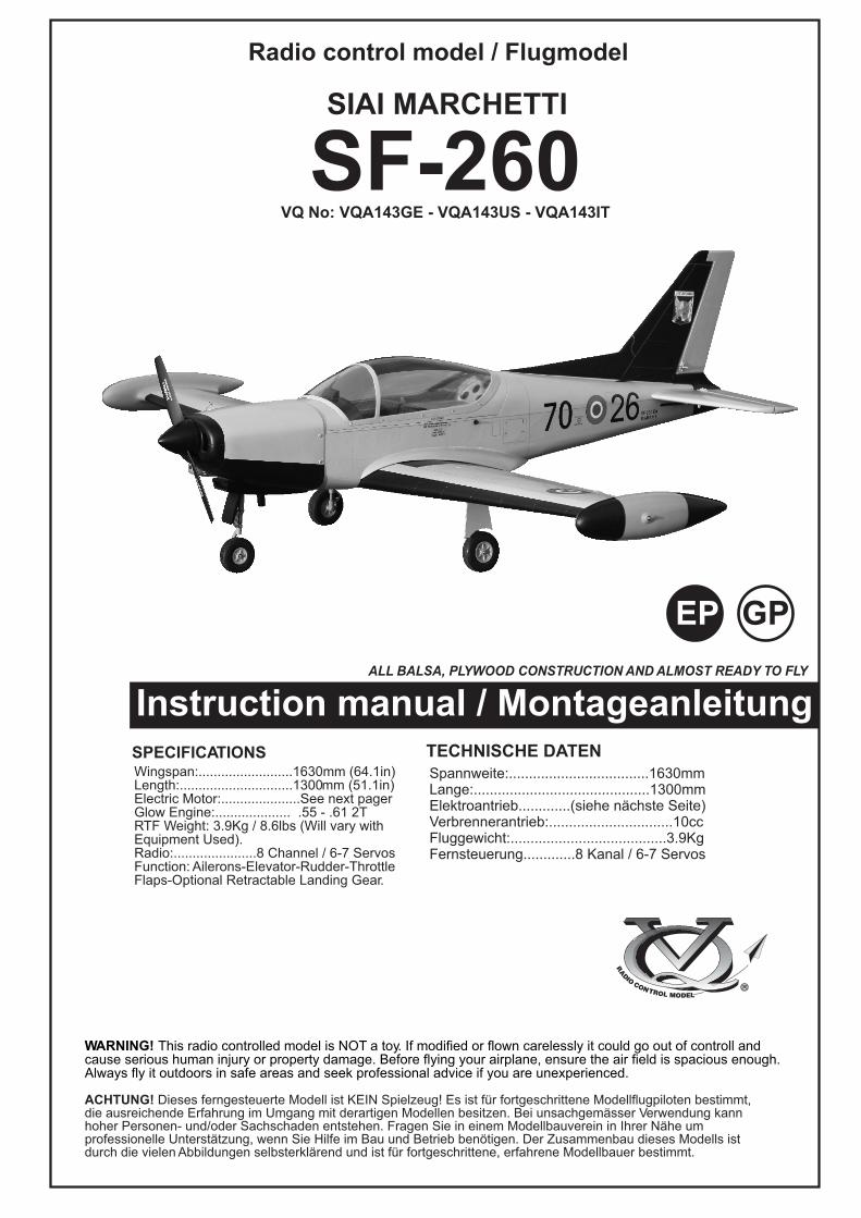
SPECIFICATIONSWingspan:.........................1630mm (64.1in)Length:..............................1300mm (51.1in)Electric Motor:.....................See next pagerGlow Engine:.................... .55 - .61 2TRTF Weight: 3.9Kg / 8.6lbs (Will vary withEquipment Used).Radio:......................8 Channel / 6-7 ServosFunction: Ailerons-Elevator-Rudder-ThrottleFlaps-Optional Retractable Landing Gear.
WARNING! This radio controlled model is NOT a toy. If modified or flown carelessly it could go out of controll andcause serious human injury or property damage. Before flying your airplane, ensure the air field is spacious enough.Always fly it outdoors in safe areas and seek professional advice if you are unexperienced.
ACHTUNG! Dieses ferngesteuerte Modell ist KEIN Spielzeug! Es ist für fortgeschrittene Modellflugpiloten bestimmt,die ausreichende Erfahrung im Umgang mit derartigen Modellen besitzen. Bei unsachgemässer Verwendung kannhoher Personen- und/oder Sachschaden entstehen. Fragen Sie in einem Modellbauverein in Ihrer Nähe umprofessionelle Unterstätzung, wenn Sie Hilfe im Bau und Betrieb benötigen. Der Zusammenbau dieses Modells istdurch die vielen Abbildungen selbsterklärend und ist für fortgeschrittene, erfahrene Modellbauer bestimmt.
Radio control model / Flugmodel
ALL BALSA, PLYWOOD CONSTRUCTION AND ALMOST READY TO FLY
SIAI MARCHETTI
Instruction manual / MontageanleitungTECHNISCHE DATENSpannweite:...................................1630mmLange:............................................1300mmElektroantrieb.............(siehe nächste Seite)Verbrennerantrieb:...............................10ccFluggewicht:.......................................3.9KgFernsteuerung.............8 Kanal / 6-7 Servos
VQ No: VQA143GE - VQA143US - VQA143IT
SF-260
EP GP

Minimum 8 channel radiofor airplane with 7 servos
12x6 for .58 - 2 cycle engine12x7 for .61 - 2 cycle engine14x8 for Electric motor
Silicone tube
.55 ~ .61 - 2 cycle
.Motor control x1 .Aileron x 2
.Flap x 2 .Elevator x1 .Rudder x1
SILICONEPOXY A
EPOXY BCA
GLUE /Epoxy Glue ( 5 minute type)
Silicon sealer
Cyanoacrylate Glue
Epoxy Glue (30 minute type)
Hobby knife
Needle nose PliersPhillip screw driver
Awl
Scissors
Wire Cutters
Hex Wrench
....................................................................................................................................................................................................................................
...............................................................................................................................................................................................................................................................................................................................................................................................................
Sander
Masking tape - Straight Edged Ruler - Pen or pencil - Rubbing alcohol - Drill and Assorted Drill Bits
REQUIRED ITEMS / Zum Betrieb wird benotigt
KLEBSTOFF
1.5mm
A B
!
CAL/R
Assemble left and right sides the same way. X
Drill holes using the stated
size of drill (in this case 1.5 mm Ø)
Use epoxy glue
Take particular care hereHatched-in areas:remove covering film carefully
Not included.These parts must be
purchased separately
Check during assembly that theseparts move freely, without binding
Apply cyano glue
!
If exposed to direct sunlight and / or heat, wrinkles can appear. Storing the model in a collplace will let the wrinkles disappear. Otherwise, remove wrinkles in covering film with a hair-dryer, starting with low temperature. You can fix the corners by using a hot iron.
Bei Sonneneinstrahlung und / oder Warme kann die Folie erschlaffen bzw. Falten entstehen.Verwenden Sie ein Warumluftgeblase (Haartrockner) um evtl. Falten aus der Folie zu bekommen. Die Kanten konnen Sie mit einem Bugeleisen behandeln. Nicht zuviel Hitzeanwenden
Read through the manual before you begin, so you will have an overall idea of what to do.
CONVERSION TABLE1.0mm = 3/64”1.5mm = 1/16”2.0mm = 5/64”2.5mm = 3/32”
3.0mm = 1/8”4.0mm = 5/32”5.0mm = 13/64”6.0mm = 15/64”
10mm = 13/32”12mm = 15/32”15mm = 19/32”20mm = 51/64”
25mm = 1”30mm = 1-3/16”45mm = 1-51/64”
Li-Po Battery 5.300 - 22.2v
ESC 80A
Motor Brushless1000 Watt
Extension cord for aileron servos: 50cm(x2)Extension cord for flap servos: 50cm(x4)Extension cord for retract servos: 30cm(x2)Extension cord for Rx battery pack: 20cm(x1)

WING BOTTOM-VIEW
Using the thread (pre-installed at factory) to slide the aileron and flap extension cord into the wing half.
Using the adhesive tape to secure the one end of the aileron and flap extension cord in place.
Using the adhesive tape to secure the oneend of the aileron and flap extension cord in place.
X30cm Extension cord
Thread
Aileron servo hatch
Turn the screws and full the aileron andflap servo hatch out of the wing half.
Thread
Flap servo hatch
Adhesive tape
WING TOP-VIEW
L/R
1.5mm
cut away only the covering
X
45o
Flap servo
1-Aileron extension cord installation Siai Marchetti SF-260
2- Flap servo installation
L/R
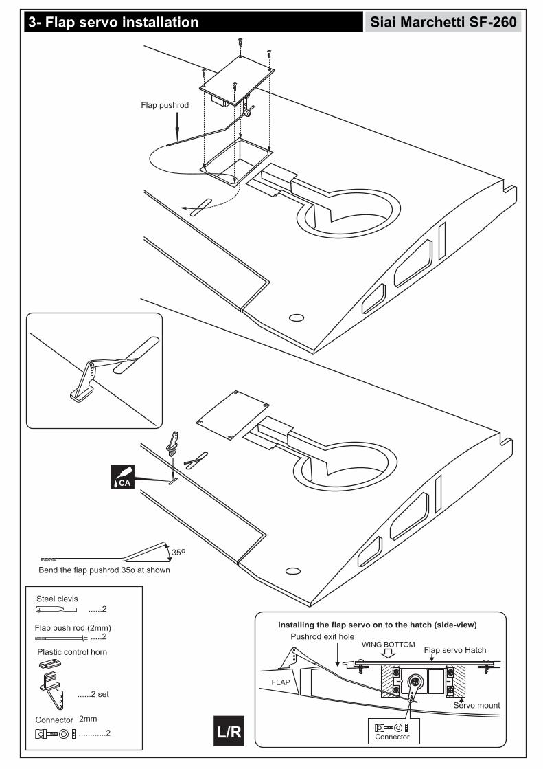
Flap pushrod
CA
Installing the flap servo on to the hatch (side-view)
Flap servo Hatch
Servo mount
Connector
WING BOTTOMPushrod exit hole
FLAP
3- Flap servo installation Siai Marchetti SF-260
L/R
Plastic control horn
......2 set
............2
2mm Connector
Flap push rod (2mm)
......2
.....2
Steel clevis
Bend the flap pushrod 35o at shown
35

90o
Aileron servo
Installing the aileron servo on to the hatch (side-view)
Aileron servo Hatch
Servo mount
WING BOTTOM
AIL.
1.5mm
cut away only the covering
X
4- Aileron servo installation Siai Marchetti SF-260
L/R
Plastic control horn
............2 set
Aileron push rod (2mm)
......2
.....2
Steel clevis
.....2
EZ link
Aileron linkage
Steel Clevis
EZ link

Note: Do not glue the woodenring to the strut at this time.
5- Electric retract and Strut installation Siai Marchetti SF-260
L/R
XX
2
1

6- Electric retract and Strut installation Siai Marchetti SF-260
L/R
CACA

Ply gear mount plate x 2
Plywood Gear mount x 2
3x20mm screw.......16
Nylon gear strap
.......4
7ASlide the landing gear onto theplywood gear mount and pushthe landing gear as shown.
7BUsing the nylon gear strap as a template, mark the plywood gear mount where the four holes to be drill.
Remove the nylon gear strap and drill a 2mm holeat each of the four marksmarked.
7C 7D
7EAttach the ply gear mount plateto the plywood gear mount
Secure the ply gear mountplate in place using CA glue.
7F 7GDrill a 2mm holes through the square plastic and ply gear mount plate.Secure the ply gear mountusing four 3x20mm screws.
CA
Reposition the nylon gear strap and secure them in place using four 3x20mm screws.
2mm
CA
Attach the square plasticonto the ply gear mount,secure it in place usingCA glue.
7H
Square plasticx2
TOP VIEW
BOTTOM VIEW
7- Fixed gear installation Siai Marchetti SF-260

8- Fixed gear installation continued Siai Marchetti SF-260
L/R
3x12mm
3x12mm self tapping screw
....................8
...........2

A B
Draw the center line on the wing joiner
- Trial fit each part before gluing . Be certain that there are no gaps. If the parts will join, but with a gaps, sand or trim the parts a little at a time until the parts meet exactly with no gaps.- Check for the correct dihedral angle
Before gluing:
- Draw the center line on the wing joiner.
30 min. Epoxy
Coat one half of the dihedral brace with epoxy up to the center line. Install the epoxy-coated side of the dihedral brace into the wing joiner cavity up to the center line.
A BCA
6x20mm dowel
2x6mm
1.5mm
1.5mm
9- Fixed gear installation Siai Marchetti SF-260
10- Joining the wing halves
L/R
2x6mm self tapping screw
.....................4

Carefully slide the wing halves together, ensuring that they are accurately aligned. Firmly press the two halves together, allowing the excess epoxy to run out. Note: The two wing halves roots must fit together perfectly. Clear off the excess epoxy.
! Make sure to glue securely, If not properly glued, a failure in flight may occur.
Glue must go inside
Wing joiner
Glue
Wing half
Hold the wing halves together with paper clamp and rubber band.
IMPORTANT: Please do not clean off the excess epoxy on the wing with strong solvent or pure alcohol, only use kerosene to keep the colour of your model not fade.
30 min. Epoxy
WING TOP-VIEW
Rubber band(not include)
Paper clamp(not include)
Nylon wing bolt(included)
WING TOP-VIEW
A B
A B
A B
30 min. EpoxyWING TOP-VIEW
A B
Siai Marchetti SF-260 11- Joining the wing halves
12- Wing tip Tank
CA
L/R

Siai Marchetti SF-260 13- Horizontal Stabilizer installing
Push the horizontal stabilizer into the slot on the fuselage as show. Check the alignment of the horizontal stabilizer
by measuring from a fixed point along the center line of the fuselage to the leading edge on each side of the
horizontal stabilizer. The distance must be equal on bothsides . If not, adjust the stabilizer until the measurements
are the same (see picture below: A=A’).
When you are satisfied with the alignment, usea pencil to trace around the top and bottom ofthe stabilizer where it meets the fuselage.
Cut away onlythe covering both sides.
Remove the horizontal stabilizerfrom the fuselage. Using a straight edgeand a sharp hobby knife, carefully cut awaythe covering inside the lines which were markedabove. Be cautious not to cut into the wood-thiswill weaken the structure.
Pull the left and right elevator out of the horizontal stabilizer.
Using a sharp hobby knife, carefully cut away the coveringaround of all slots for the horizontal stabilizer installation.
Cut away onlythe covering
13A
13B
13C
13D
A A’
A=A’
Center point

Siai Marchetti SF-260 14- Horizontal Stabilizer installing continued
15- Rudder and Elevator
! Securely glue together. If coming off during fly, you lose control of your air plane.
CAApply thin CA glue where the fuselage meet the horizontal stabilizer (both sides).
Install the horizontal stabilizer onto the fuselage and adjust the alignment as described in steep 13B. Note: it is important to ensure that the horizontal stabilizer is also level in regards to the fuselage.Apply the thin CA along the area where the covering was removed in the previous step and to the
fuselage where the horizontal stabilizer mounts .
Apply thin CA glue on the top and bottom of the hinge
HORIZONTAL STABILIZER
TOP-SIDE
CA
CA
CA

Control horn Alignment
STABILIZER
Attach the rudder control horn using the hardware provided(two 2x15mm screws and a back plate).
Plastic control horn
2x15mm screw
............................3
.....................6
Plastic back plate
...........................3
2mm 2mm
2mm
Siai Marchetti SF-260 16- Control horn installation
17- Engine
2x12mm
! Align the mark on both engine mount beams with the mark on the fuselage
Attach the engine mount beams onto the fire-wall so the distance between of two engine mount beams is “A”,and B=B’ as show.Secure the engine mount beams onto the fire-wall with litter CA glue (1B)
Using a pencil or felt tipped pen, mark the fire wall where the four holes are to be drilled(1B))
6mm
A
B
B’
B=B’
CA
A
B
B’
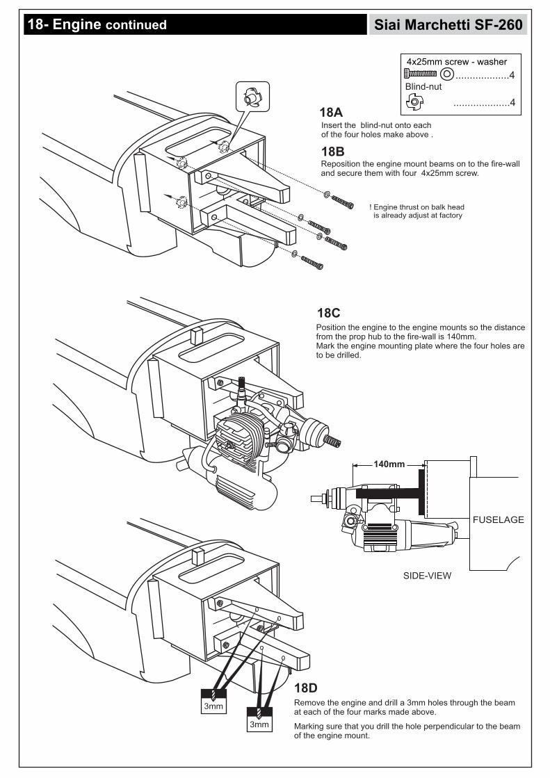
Reposition the engine mount beams on to the fire-wall and secure them with four 4x25mm screw.
...................4
....................4
4x25mm screw - washer
Blind-nut
Insert the blind-nut onto each of the four holes make above .
! Engine thrust on balk head is already adjust at factory
140mm
FUSELAGE
3mm
SIDE-VIEW
Siai Marchetti SF-260 18- Engine continued
3mm
Position the engine to the engine mounts so the distance from the prop hub to the fire-wall is 140mm.Mark the engine mounting plate where the four holes are to be drilled.
Remove the engine and drill a 3mm holes through the beam at each of the four marks made above.
Marking sure that you drill the hole perpendicular to the beam of the engine mount.
18A
18B
18C
18D

Using a aluminum motor mounting plate as a template, mark the plywood motor mounting plate where the four holes are to be drilled.
Remove the aluminum motor mounting plate and drill a 1/8”(3mm) hole through the plywood at each of the four marks marked .
3mm
! Align the mark on wooden motor mounting plate with the mark on the fire-wall.
Using a wooden motor mounting plate as a template, mark the fire-wall where the four holes are to be drilled.
X
To muffler
Filler tube
To engine
3x35mm screw
Rubber stopper
Checking for leaks - block the vents and blow into the feed - if in doubt submersing the tank in a blow of water will show up any problems.
Blow
Water
Siai Marchetti SF-260 19- Engine continued
20- Fuel tank
21- Electric Motor
Reposition the engine on the engine mount beams, aligning it with the holes. Secure the engine to the engine mount using four 3x25mm screws.
Note: Apply Silicon sealer to each of the 3x25mm screw and nut.
.......43x25mm screw
Washer .......4
3mm nut
.......4
21A
21B
21C
3mm
X

B=B’! Motor thrust on balk head is already adjust at factory
6x100mm bolt.....4
6mm nut..........12
6mm washer...16
SIDE-VIEW
B’
B
FUSELAGE
Attach the four 6x100mm bolts and nuts to the fire-wall as shown.
3mm bolt / nut...4
Secure the Motor to the woodenmotor mounting plate using thefour 3mm bolts.
5mm
Remove the wooden motor mounting plate and drill a 5mm hole through the fire-wall at each of the four marks marked .
140mm
Siai Marchetti SF-260 22- Electric Motor continued
22A
22B
22C
6x100mm bolt
22D

1.5mm
Siai Marchetti SF-260 23- Nose Gear (Electric retract and strut)
90o
Rudder servo

Screw steering arm on the leg.
Slide in the front gear leg with the flat to back through the bearing and steering arm.
Nose gear mount
3x15mm screw...4
Steering arm...1
..............1
3mm nut, washer...4
90o
Rudder servo
Siai Marchetti SF-260 24- Nose Gear (Fixed gear)
24A
Insert “z” bend of steering linkage inside the hole of front landing gear steering arm
24B
Place the nose gear mount onto the fire-walland secure it in place using the four 3x15mmscrews.
Position the steering arm inside the front landing gear mount already.
24C
24D
24E
65mm diameter wheel
4mm colar4mm colar
4mm colar........2

................1
....................22mm
Connector
X
3mm set Screw
2 mm
Elevator pushrod
Elevator pushrod
Elevator push rod
Rudder push rod
Throttle push rod
Siai Marchetti SF-260 25- Servo and Linkage
LINKAGE - IN CASE OF ELECTRIC MOTOR USING
LINKAGE - IN CASE OF GLOW ENGINE USING
Elevator servo
Rudder servo
Elevator servo
Rudder servo
5mm

Cut off shaded portion
Siai Marchetti SF-260 26- Servo and Linkage
70 STORMOO
70 STORMOO
70 26
RUOTARE LA MANOVELLAFAR SCORRERE IL TETTUCCIO
TURN HANDLESLIDE CANOPY
RUOTARE LA MANOVELLAFAR SCORRERE IL TETTUCCIO
TURN HANDLESLIDE CANOPY
SOCCORSO
RESCUE
SOCCORSO
RESCUE
STATIC PORT
KEEP CLEAN
RUOTARE LA MANOVELLAFAR SCORRERE IL TETTUCCIO
SOCCORSO
70 STORMOO
27- Decal
ITALY AIR FORCE VERSION
2.5x12mm self tapping screw
...........5
2mm
1.5mm
2.5mm self tapping screw
1.5mm
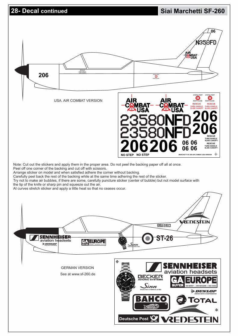
Siai Marchetti SF-260 28- Decal continued
206206
206 0606
MARCHETTI SF-260 AIR COMBAT USA VERSION
STATIC PORT
KEEP CLEAN
RESCUETURN HANDLESLIDE CANOPY
RESCUETURN HANDLESLIDE CANOPY
RESCUETURN HANDLESLIDE CANOPY
STATIC PORT
KEEP CLEAN
206 RESCUETURN HANDLESLIDE CANOPY0606
06
STATIC PORT
KEEP CLEAN
RESCUETURN HANDLESLIDE CANOPY
206
USA. AIR COMBAT VERSION
ONE MARKET ONE MAGAZINE ONE CHOICE
DRIVE WITH CONFIDENCE
Deutsche Post
ONE MARKET ONE MAGAZINE ONE CHOICEDRIVE WITH CONFIDENCE
ST-26
GERMAN VERSION
Note: Cut out the stickers and apply them in the proper area. Do not peel the backing paper off all at once. Peel off one corner of the backing and cut off with scissors. Arrange sticker on model and when satisfied adhere the corner without backing.Carefully peel back the rest of the backing while at the same time adhering the rest of the sticker.Try not to make air bubbles, if there are some, carefully puncture sticker (center of bubble) but not model surface with the tip of the knife or sharp pin and squeeze out the air. At curves stretch sticker and apply a little heat so that no ceases occur.
See at www.sf-260.de

DO NOT try to fly an out-of-balance model !
RUDDER
AILERON
IMPORTANT: Flying your model at these throws will provide you with the greatest chance for successful first flights. If,after you have become accustomed to the way the Siai Marchetti SF-260 flies, you would like to change the throws to suit your taste that is fine. However, too much control throw could make the model difficult to control, so remember, “more is not always better”.
ELEVATOR
20mm
40mm
15mm
1- Mount the wing to the fuselage. Using a couple of pieces of masking tape, place them on the top side of the wing (98mm) back from the leading edge, at the fuselage sides.
2- Turn the plane upside down, lift the airplane. Place your fingers on the masking tape and carefully lift the plane.
3- If the nose of the plane falls, the plane is heavy nose. To correct this, move the battery pack further back in the fuselage. If the tail of plane falls, the plane is tail heavy. To correct this, move the battery forward or if this is not possible, stick weight onto the firewall. When balanced correctly, the airplane should level or slightly nose down when you lift it up with your fingers.
LATERAL BALANCE:
After you have balanced a plane on the CG, you should laterally balance it. Doing this will help the airplane track straighter.
1- Turn the airplane upside down. Attach one loop of heavy string to the engine crankshaft and one to the tail wheel wire. With the wing level, carefully lift the airplane by the string. This may require two people to make easier.
2- If one side of the wing fall, that side is heavier than the opposite. Add small amounts of lead weight to the bottom side of the lighter wing half’s wing tip. Follow this procedure until the wing stays level when you lift the airplane.
CG
Siai Marchetti SF-260 29- Balancing
FLAP
THE CENTER OF GRAVITY IS LOCATED BACK FROMTHE LEADING EDGE OF THE WING, AT THE FUSELAGE. BALANCETHE PLANE UPSIDE DOWN WITH THE FUEL TANK EMPTY.
30- Control throws
98mm
Position for right diagram.
Position for right diagram.
40mm
20mm
15mm
20mm