A survey on modeling guidelines for quantity takeoff-oriented BIM-based design

April 2021
Smithsonian Facilities BIM Guidelines

Smithsonian Facilities BIM Guidelines
April 2021 Page ii
TABLE OF CONTENTS LIST OF FIGURES ......................................................................................................................... III
LIST OF TABLES ........................................................................................................................... III
DOCUMENT REVISION LIST ..........................................................................................................IV
1.INTRODUCTION ......................................................................................................................... 1
2.BIM PROJECT EXECUTION PLAN (PXP) REQUIREMENTS .............................................................. 2 2.1 BIM Execution Plan Overview ................................................................................................................................ 2 2.2 Procurement Strategy and the PxP ....................................................................................................................... 2 2.3 BIM Sharing ............................................................................................................................................................ 2
Design ....................................................................................................................................... 2 Construction Documents/Bid Set ............................................................................................... 3 Construction Phase ................................................................................................................... 3
2.4 BIM Responsibilities ............................................................................................................................................... 3 2.5 BIM Software .......................................................................................................................................................... 3 2.6 BIM Goals and BIM Uses in the PxP ...................................................................................................................... 5
Existing Conditions Modeling..................................................................................................... 5 Design Authoring ...................................................................................................................... 6 Design / Model Review .............................................................................................................. 6 3D Model Coordination / Clash Detection (“Interference Checking”).......................................... 7 SF Asset Management ............................................................................................................... 8 As-Built / Record Modeling ........................................................................................................ 8
2.7 BIM LOD Requirements ....................................................................................................................................... 10
3.SF REVIT TEMPLATES AND REVIT TEMPLATE USER GUIDE ......................................................... 11 3.1 Overview of the Templates ................................................................................................................................. 11 3.2 SI-GIS and Space Naming ..................................................................................................................................... 11 3.3 Model Ownership and After-Project Use............................................................................................................ 12
4.FILE ADMINISTRATION ............................................................................................................ 12 4.1 Model, View and Sheet File Naming ................................................................................................................... 12
SF Model File Naming .............................................................................................................. 12 SF View Naming ...................................................................................................................... 13 SF Sheet Naming ..................................................................................................................... 13 Sketches and Supplemental Drawing File Names ..................................................................... 14 SF Combined PDF Naming ....................................................................................................... 18
4.2 Federated Model File Coordination .................................................................................................................... 19 4.3 Electronic File Storage ......................................................................................................................................... 19
5.PROJECT DELIVERABLE STANDARDS ......................................................................................... 20 5.1 Project Folder Structure ...................................................................................................................................... 20 5.2 Project Collaboration and Data Security ............................................................................................................. 20
Smithsonian Facilities BIM Guidelines
April 2021 Page iii
5.3 BIM Deliverables .................................................................................................................................................. 21 Design ..................................................................................................................................... 21 Construction ........................................................................................................................... 25 Final Deliverables/As-Built Documentation .............................................................................. 26
5.4 Autodesk Revit BIM Deliverables Checklist......................................................................................................... 26 5.5 CAD Deliverables from BIM ................................................................................................................................. 27
Sheet Drawing Submission Standards ...................................................................................... 27 Standard Title Block and Cover Sheet ...................................................................................... 30 SI Sheet Sizes .......................................................................................................................... 31 SF Project Units, Fonts and Dimensions ................................................................................... 32 Symbols .................................................................................................................................. 33 SI Space Class Determination for GIS and TRIRIGA Facilities Center .......................................... 35
LIST OF FIGURES Figure 4-1: File Naming Structure ...................................................................................................................................... 12 Figure 4-2: Sheet Numbering System and Sheet File Naming System ............................................................................. 14 Figure 5-1: Project Folder Structure................................................................................................................................... 20 Figure 5-2: Custom SF annotation symbols ....................................................................................................................... 33 Figure 5-3: Custom SF view title symbols .......................................................................................................................... 33 Figure 5-4: SF CAD symbols available from the Smithsonian Facilities A/E Center website ........................................... 34
LIST OF TABLES Table 2-1: BIM Software by Discipline/Use for Project Development ............................................................................... 4 Table 2-2: BIM Uses .............................................................................................................................................................. 9 Table 2-3: Summary of the BIM Forum Level of Development (LOD) Definitions ........................................................... 10 Table 4-1: Components of the BIM file name(s) ............................................................................................................... 12 Table 4-2: Discipline Codes ................................................................................................................................................. 15 Table 4-3: Drawing Type Codes .......................................................................................................................................... 17 Table 4-4: Sheet Sequence Numbers ................................................................................................................................. 18 Table 4-5: Components of the Combined PDF file name.................................................................................................. 18 Table 5-1: Design Deliverables ........................................................................................................................................... 24 Table 5-2: BIM Deliverable Checklist.................................................................................................................................. 26 Table 5-3: Layer Standards for Standard Base Plans – Site Plan....................................................................................... 28 Table 5-4: Layer Standards for Standard Base Plans – Floor Plan .................................................................................... 29 Table 5-5: SI Sheet Sizes...................................................................................................................................................... 31

Smithsonian Facilities BIM Guidelines
April 2021 Page iv
Document Revision List
Task Details Revision Date
Document organization Rearranged some sections for better flow in the document
Naming convention Changes as per SF naming convention in SF CAD Standards
Discipline code changes Changes as per NCS 5.0 and SF CAD Standards
Title block changes Automation of some fields led to rearrangement of them on title block
Wall section and detail section annotation changes
Wall section and detail section annotation changes
Document title Changed from SF BIM Standards to SF BIM Guidelines
Oct. 2016
File naming convention Change of OFEO to Smithsonian Facilities Oct. 2016
BIM deliverable changes Adding details about the federated model file types and 3D PDF deliverables
Oct. 2016
Document organization Rearranged some sections for better flow in the document
Nov 2016
Project Folder Structure Highlighted project folder structure image March 2017
Model File Naming Edits Added option for submission type in lieu of submission date
March 2017
SF Combined PDF Naming Added combined PDF naming March 2017
Model Review Report Clarification and instructions when deviations occur in a project
March 2017
3D PDF Eliminate 3D PDF Requirements October 2017
Laser Scanning Added additional notes for Laser Scanning Requirements
October 2017
Clash Detection Revised Clash Detection Section October 2017
BIM Deliverables Updated Deliverable Requirements October 2017
Text Size Text height Requirement has been changed to 3mm (1/8”)
October 2017
Layering Standards Revised Layering Standards September 2018
Asset Management Revised Asset Management to align with new requirements
September 2018
SI Space Naming Guidelines Added Space Naming Guidelines September 2018
LOA Requirements Added LOA Requirements for Modeling September 2018
Construction / Bid Set Added documents that may be available April 2021
Electronic File Storage Added OneDrive April 2021

Smithsonian Facilities BIM Guidelines
April 2021 Page 1 of 38
1. INTRODUCTION Building Information Modeling, or BIM, is utilized throughout the building industry for developing and documenting building projects, from early in the conceptual design phase through to project delivery.
“Building Information Modeling (BIM) is a digital representation of physical and functional characteristics of a facility. A BIM is a shared knowledge resource for information about a facility forming a reliable basis for decisions during its life-cycle; defined as existing from earliest conception to demolition. BIM is used for the purpose of visualization, engineering analysis, conflict, analysis, code criteria checking, cost engineering, as-built product, budgeting and many other purposes…” -- National BIM Standard - United States (NBIMS)
The Smithsonian Institution (SI) encompasses over 12 million square feet of space in over 640 buildings in the US, Panama, and other international locations. Management of Building Information Models (BIM) at the SI is the responsibility of the Smithsonian Facilities office, the organization that is responsible for both in-house design efforts and administration of repair, renovation and new construction projects for the museums and other facilities.
The purpose of this manual is to convey the key processes, responsibilities and details for BIM development for SF projects by architecture, engineering and construction (AEC) consultants. The goal of the standards documents is to assure accurate and consistent project deliverables.
This document includes guidance for drawing appearance, BIM element standards and symbols, and deliverable requirements. The SF BIM Standards is one of several interrelated documents that assist project teams to fulfill the SI’s project requirements. Additional SF BIM-related guidance includes:
• SF BIM Integration Flowchart
• SF CAD Guidelines
• SF Revit Model Review Instructions
• SF BIM Execution Plan Framework Document
• SF BIM Content LOD Matrix
• SF Revit Template User’s Guide
• SF Revit Templates (Architectural, Mechanical/Plumbing, Electrical, Structural, & Fire Alarm / Security BIM files)
• Revit Model Review Checker • Specification Section – 01 3250 BIM Requirements
• Specification Section – 01 7823 O&M Data Requirements
• SF Facility Asset Data Spreadsheet
• SI Space Naming Guidelines

Smithsonian Facilities BIM Guidelines
April 2021 Page 2 of 38
2. BIM PROJECT EXECUTION PLAN (PXP) REQUIREMENTS Smithsonian Facilities requires that a BIM Project Execution Plan (PxP) be developed for project employing BIM. The “SF BIM Execution Plan - Framework Document” has been developed as a template by Smithsonian Facilities to assist project teams developing BIM execution plans, consistently across all SF BIM projects.
2.1 BIM Execution Plan Overview BIM Project Execution Plans will be living documents, updated by the consultant team throughout project development and delivery then transferred to the Contractor for updating throughout the construction. The BIM PxP works in concert with the other SF BIM guidance documents noted in Section One.
Any changes made to the BIM PxP during the course of a project must be approved by the authoring party, and reviewed and approved by the SI’s COTR (Contracting Officer's Technical Representative) for the project.
2.2 Procurement Strategy and the PxP The BIM Execution Plan (PxP) will be tailored to align with the project’s procurement method (such as Design-Bid-Build (DBB), CM at Risk, Design-Build (DB), etc.
Procurement strategies will influence whether there are separate design and construction BIMs and who will be the responsible party for the final project BIM deliverable. Separate contracts will require a separate BIM PxP, but should align with each other to ensure a collaborative process.
When a project BIM is to be developed collaboratively for both design/documentation and construction, the BIM Execution Plan (PxP) should address how the model(s) can be handed-off between stages effectively.
2.3 BIM Sharing Project development is an intrinsically collaborative process. The PxP will detail BIM authoring tools, data integration, and collaborative team workflow environments that will be employed throughout the project BIM development process.
Listed below are the possible BIM information products that will be delivered during different stages of the project lifecycle.
Design
The A/E design consultants for a project shall be responsible for providing Design Intent Model(s) as part of project deliverables, as described in the project scope of work. The design phase PxP will describe the details of the project model, including file formats, coordination/federation of the model(s), and format for deliverables.

Smithsonian Facilities BIM Guidelines
April 2021 Page 3 of 38
Construction Documents/Bid Set
For projects having a bid phase, BIM requirements will be defined and reviewed with potential bidders. The design phase PxP will be provided as part of the overall SF BIM guidance for the project.
Prior to the start of construction, the following building information, obtained and developed by the Architect and/or Engineer during the design phase, may be available to the Contractor for the development and use by the contractor during the construction process:
1. Design Intent Model(s) (.rvt, .ifc, .nwc, .nwd, .dwg) 2. Contract Documents (.pdf, .dwg) 3. Point Clouds (.rcs) 4. Scans of the original building design drawings (.pdf) 5. BIM PxP (.docx, .pdf) 6. LOD Matrix (.xlsx, .pdf) 7. SF Facility Asset Data Spreadsheet (.xlsx)
The Contract Documents are the binding document(s), the Design Intent Model(s) are provided for reference only.
Construction Phase
• It is the contractor’s responsibility to assure that all major trades are modeled as per the contract and used for clash detection, construction phasing, and installation coordination and noted in the PxP.
• Subcontractor’s fabrication model(s) shall be coordinated within the Coordination model(s)and noted in the PxP.
• Clash analyses and reports for the project will be detailed in the project PxP.
2.4 BIM Responsibilities The PxP will detail all parties’ responsibilities in the project BIM development process.
2.5 BIM Software The Smithsonian BIM practice employs Autodesk Revit as their primary BIM authoring application. The software version that is used for project BIM development will be noted in the BIM PxP.
Smithsonian Facilities will advise project consultants on the preferred version of any software to be used before project execution. Any deviation from that version must be approved by the SI project COTR prior to commencement of work. The SF will approve version updates, if necessary, for multi-year projects during the course of project development.
The following table shows a list of current acceptable BIM and CAD applications for SF projects. This list does not preclude the utilization of other software for the prescribed uses. Software other than listed below may be used but are subject to SI project COTR’s approval due to interoperability requirements.

Smithsonian Facilities BIM Guidelines
April 2021 Page 4 of 38
Table 2-1: BIM Software by Discipline/Use for Project Development
BIM Use Discipline Software Version
Architecture Design
Architecture AutoCAD and Revit As agreed by SF and project consultant at project initiation Structure
Design Structure AutoCAD (Add-on) and Revit
HVAC Design HVAC Revit / AutoCAD (Add-on) CADduct and CADmech
Plumbing Design
Plumbing Revit / AutoCAD (Add-on) CADduct and CADmech
Electrical Design
Electrical Revit / AutoCAD (Add-on) CADelec
Civil Design Civil AutoCAD Civil 3D
Fire Protection Design
Fire Protection MEP CAD AutoSprink
HVAC Fabrication
HVAC Revit / AutoCAD (Add-on) CADduct and CADmech
Plumbing Fabrication
Plumbing Revit / AutoCAD (Add-on) CADduct and CADmech
Electrical Fabrication
Electrical Revit / AutoCAD (Add-on) CADelec
Fire Protection Fabrication
Fire Protection MEP CAD AutoSprink
Structure Detailing
Structure Revit / AutoCAD (Add-on)
Coordination CM Coordination
Navisworks Manage, Revizto
Model Check All disciplines (as detailed in the project scope of work)
Revit Model Review report, output to a PDF format (converted from *.html format)
Design Review
All disciplines Bluebeam, Revizto, I-Manage

Smithsonian Facilities BIM Guidelines
April 2021 Page 5 of 38
2.6 BIM Goals and BIM Uses in the PxP BIM goals are included within the Project Execution Plan to summarize the scope of the project BIM development effort. BIM utilization for AEC project development may include existing conditions modeling; design visualization; design reviews; clash detection and constructability exercises; asset and space data development; and as-built documentation.
Existing Conditions Modeling
Description: A process in which a project team develops a 3D model of the existing conditions for a site, facilities on a site, or a specific area within a facility. This model can be developed in multiple ways, including laser scanning and conventional surveying techniques.
An existing condition model may be used as a basis for design studies, sight line studies, move management and logistics, day lighting, area calculations, space allocation studies, volume calculations for HVAC, planning standards, phasing studies, testing locations, and other studies relevant to the project Scope of Work (SOW). The project SOW will define the approximate area, relevant building systems, and associated equipment to be modeled. The BIM PxP will define the agreed upon modeling effort.
The SI COTR will provide access to master drawings, any partial models for preliminary modeling and current exports from SI’s Facility Center (Tririga) of space and asset data. Field verification is part of this process unless otherwise specified by SI. All applicable SF BIM and CAD standards and requirements apply.
At a minimum, an existing conditions model will contain:
• The visible architecture elements walls, floors, ceilings, columns, and roof. These elements are to be modeled to LOD 300 with an LOA of 12mm (½”) unless noted otherwise in SOW.
• Assembly and product information must be added to the model as required by the SOW. • Space volumes and data (numbers, functional use, space ownership) • Date attribute field noting as to when the existing conditions were verified, indicating the
currency of the model and its associated data.
Optional:
• Element(s) may be modeled to a greater LOD and/or LOA in accordance with the SOW. • MEP equipment and routing may be modeled in accordance with the SOW. • Assets, furniture and fixtures may be modeled in accordance with the SOW. • Extend the modeling beyond the immediate SOW areas to show context and additional
information based on project needs.
Laser Scanning for Existing Conditions
Laser scanning is a technology-based process for capturing 3D environments, including distances, in a 3D digital model called a point cloud, which is comprised of millions of measured points.

Smithsonian Facilities BIM Guidelines
April 2021 Page 6 of 38
The SI COTR will evaluate the cost and efficiency benefits of laser scanning to capture existing conditions, as well as the optional conversion of the point cloud data to BIM, based upon the size and complexity of the project. The scope and procedure for the laser scanning, and conversion to BIM, if specified, will be clearly stated in the project BIM PxP.
The required object surface density shall be a minimum of 6mm (¼”). RGB color shall be mapped to both the exterior and interior scans. Selected areas or objects may require a greater object surface density as directed by COTR and/or SOW.
Design Authoring
Description: A key process in which 3D software applications are used to develop a Building Information Model (BIM) that illustrates the design intent.
The first step in design authoring for an SF project is to incorporate SF Revit template(s) as a part of the project BIM. A project BIM may include multiple component models including the architectural, HVAC, electrical, plumbing, structural, fire protection, life safety and security disciplines. Typically, multiple engineering models may be linked to or federated with, the architectural model, as required by the project scope.
BIM authoring software shall be used to model parametric components and objects. Modeled objects shall contain parameters and associated data applicable to the building system. The level of development in a project model will accumulate as the project matures. This is noted within the SF BIM Content LOD Matrix. At minimum, project LOD must include all features that will accurately describe the design solution.
1. At a minimum, all required models shall be detailed to the Level of Detail required by each design phase and/or sub-phase.
2. BIMs should include all geometry, physical characteristics, information and data necessary so to describe and facilitate the design, intended construction, and cost estimating of a project, meeting the requirements noted in project’s BIM Content LOD Matrix, for each design phase and/or sub-phase of a project.
3. All drawings, simulations, and services required for analysis and review shall be extractions from the project BIM(s).
4. Modeled elements in the project BIM need not illustrate the individual parts required for the assembly and/or the manufacture of the component. The intent of the project model is to provide a level of detail to describe the overall size, shape, clearances, information, data for building components and coordination with other components and work.
Design / Model Review
Description: A process in which the project BIM is evaluated against a set of established criteria/rules. The criteria can cover compliance with spatial requirements, data or parameter completion, and established drawing standards.

Smithsonian Facilities BIM Guidelines
April 2021 Page 7 of 38
Model Checking
The SF has developed a customized rule set for use with Revit Model Review add-in application to verify the completion of project models. The add-in application can be downloaded from the Autodesk subscription website, for installation into Revit. The SF configuration file is available for download from the Smithsonian Facilities A/E Center website.
As part of the model development process, the project A/E team should periodically perform automated checks of the Revit model. Model review check reports are required to be run by the project BIM team and delivered for every SF project milestone BIM deliverable. Additional rules can be added to the configuration as needed.
Note that some of the checks may not pass the Revit model review as per the SF rule set provided. In that case, a clear explanation of the failure for each failed check in the report will be required. The explanation should comply with the specific project exceptions that are outlined in the project execution plan (BIM PxP). All exceptions or deviations from the SF BIM guidelines should be approved by the SI Project COTR and stated in the project BIM PxP.
Clash detection or collision reports allow for the identification, inspection and reporting of interferences in a 3D project model(s). These can be generated by the project team, using either Revit or Autodesk Navisworks, and reviewed by the SF in consultation with the project team.
Informal or ‘over the shoulder’ reviews can lend insight to the design development process on an ad hoc basis.
3D Model Coordination / Clash Detection (“Interference Checking”)
Description: A process during the coordination process that employs clash detection software to identify conflicts between building systems by analyzing a combined or federated model. The goal of the clash detection is to reduce the number of changes during construction due to major building interferences to zero. Clash Detection - Design: SF requires Clash Detection Reports (CDRs) from the design team at each design milestone starting at the 35% design deliverable. CDRs must include the results from an automated model checking software to indicate level of model coordination and other applicable codes. Both hard and soft clashes should be included in the model checking process. SF classifies clashes in two categories described below: Category 1 - Clashes that can be internally resolved by a single entity (consultant or subcontractor). The goal is to reduce error propagation in the design and to ensure compliance with good design practices and applicable codes and regulations. These clashes should be resolved prior to submission of a design deliverable. Category 2 – Clashes that require coordination between multiple entities. For example, this could be a clash between the structural and mechanical designs. The goal is to reduce the number and impact of

Smithsonian Facilities BIM Guidelines
April 2021 Page 8 of 38
field changes during the construction phase of the project. As a best practice, clashes should be resolved prior to submission of a design deliverable. These clashes should be resolved prior to submission of a design deliverable. At final submission models shall be free of conflicts among major systems, their subsystems and elements that would cause coordination issues during construction. For any unresolved clashes indicated in the final CDR at Final Submission, the design team must provide a separate narrative explaining why the clash could not or need not be resolved. Clash Detection - Construction: Clash detection during construction is primarily a coordination tool. As in design, both hard and soft clashes should be considered during the coordination process. During the construction phase, the accuracy of fabrication models shall be verified. Prior to each fabrication or shop drawing submittal for approval, fabrication contractors shall submit their models to the Contractor's BIM Manager for integration into the federated model for clash detection / coordination and resolution. CDRs shall be provided with fabrication or shop drawing submittals.
SF Asset Management
Description: SF has created the SF Facility Asset Data Spreadsheet, it is way to capture information regarding assets outside of the BIM for use by SF to import into their facilities management system. SF will provide A/E current export from SI’s Facility Management system at start of the project and will be a living document that is updated through the entire life of the project. In addition to the spreadsheet, customized data fields (parameters) have been incorporated and applied to components in the project BIM by use of the SF Revit Templates (Mechanical/Plumbing and Electrical).
Data populated in the required fields will be used for incorporation into the SI Facility Center (Tririga) application for asset management.
The scope and procedures for asset management will be detailed in the project BIM PxP by the AEC consulting teams, with the SI COTR’s review/approval. Please refer to the SF Facility Asset Data Spreadsheet for data fields (parameters) and requirements and SF Revit Template User’s Guide for required data fields (parameters) within the project BIM.
Refer to the project-specific document “01 7823_O&M Data Reqs” for more specificity about construction phase and asset requirements
As-Built / Record Modeling
Description: Record modeling is the process used to create a model having an accurate representation of the physical conditions, environment and assets of a facility.
The record model should, at a minimum, contain component information relating to the main architectural, structural, and MEP elements. Additional information such as custom parameters for equipment and spaces may be required.
Smithsonian Facilities BIM Guidelines
April 2021 Page 9 of 38
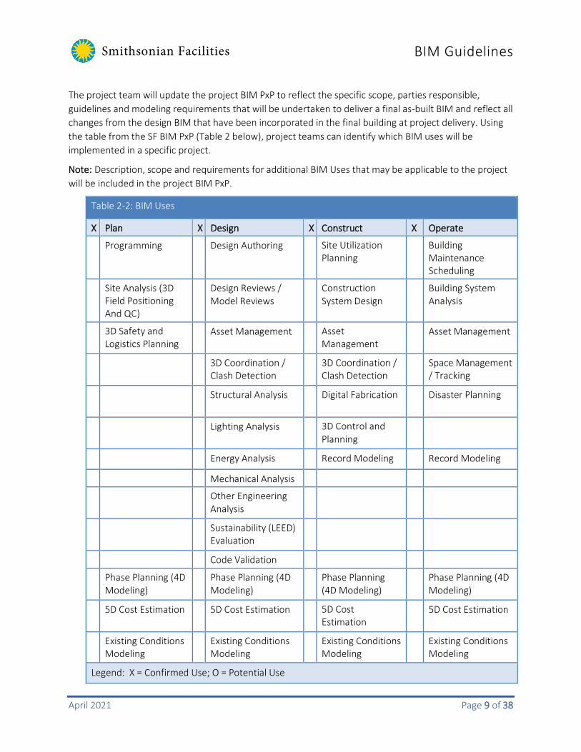
The project team will update the project BIM PxP to reflect the specific scope, parties responsible, guidelines and modeling requirements that will be undertaken to deliver a final as-built BIM and reflect all changes from the design BIM that have been incorporated in the final building at project delivery. Using the table from the SF BIM PxP (Table 2 below), project teams can identify which BIM uses will be implemented in a specific project.
Note: Description, scope and requirements for additional BIM Uses that may be applicable to the project will be included in the project BIM PxP.
Table 2-2: BIM Uses
X Plan X Design X Construct X Operate
Programming Design Authoring Site Utilization Planning
Building Maintenance Scheduling
Site Analysis (3D Field Positioning And QC)
Design Reviews / Model Reviews
Construction System Design
Building System Analysis
3D Safety and Logistics Planning
Asset Management Asset Management
Asset Management
3D Coordination / Clash Detection
3D Coordination / Clash Detection
Space Management / Tracking
Structural Analysis Digital Fabrication Disaster Planning
Lighting Analysis 3D Control and Planning
Energy Analysis Record Modeling Record Modeling
Mechanical Analysis
Other Engineering Analysis
Sustainability (LEED) Evaluation
Code Validation
Phase Planning (4D Modeling)
Phase Planning (4D Modeling)
Phase Planning (4D Modeling)
Phase Planning (4D Modeling)
5D Cost Estimation 5D Cost Estimation 5D Cost Estimation
5D Cost Estimation
Existing Conditions Modeling
Existing Conditions Modeling
Existing Conditions Modeling
Existing Conditions Modeling
Legend: X = Confirmed Use; O = Potential Use

Smithsonian Facilities BIM Guidelines
April 2021 Page 10 of 38
2.7 BIM LOD Requirements BIMForum (the U.S. Chapter of buildingSMART International) presents a standard document - Level of Development (LOD) Specification, which underlay’s SI guidance for LOD. The LOD for SF project BIMs will be detailed in the BIM Project Execution Plan (PxP) for every project.
The AIA in its Document G202 TM – 2013 Project Building Information Modeling Protocol Form provides another industry-recognized framework as a means of defining the detailed modeling requirements for a project. The LOD definitions within the BIMForum specification are identical to those published in the AIA’s updated Digital Practice Documents, with an exception of addition of LOD 350.
The table below summarizes those levels of development as defined by the BIMForum.
Table 2-3: Summary of the BIM Forum Level of Development (LOD) Definitions
LOD Description
LOD 100 The model element may be graphically represented in the model with a symbol or other generic representation, but does not satisfy the requirements for LOD 200. Information related to the model element (i.e. cost per square foot, tonnage of HVAC, etc.) can be derived from other model elements.
LOD 200 The model element is graphically represented within the model as a generic system, object, or assembly with approximate quantities, size, shape, location, and orientation. Non-graphic information may also be attached to the model element.
The model element is graphically represented within the model as a specific system, object or assembly in terms of quantity, size, shape, location, and orientation. Non-graphic information may also be attached to the model element.
LOD 350 The model element is graphically represented within the model as a specific system, object, or assembly in terms of quantity, size, shape, orientation, and interfaces with other building systems. Non-graphic information may also be attached to the model element.
LOD 400 The model element is graphically represented within the model as a specific system, object or assembly in terms of size, shape, location, quantity, and orientation with detailing, fabrication, assembly, and installation information. Non-graphic information may also be attached to the model element.
LOD 500 The model element is a field verified representation in terms of size, shape, location, quantity, and orientation. Non-graphic information may also be attached to the model elements.
Table Source: BIM Forum’s Level of Development Specification
SF projects employing BIM require a BIM Content LOD matrix to be filled out and submitted, utilizing the template provided by the SF BIM PxP’s Appendix B (a Microsoft Excel format file).

Smithsonian Facilities BIM Guidelines
April 2021 Page 11 of 38
3. SF REVIT TEMPLATES AND REVIT TEMPLATE USER GUIDE
3.1 Overview of the Templates The SF Revit Template files provide a pre-configured Revit file to serve as a starting point a new project BIMs. The SF template file contains commonly-used drawing objects and SI conventions to assist Revit users in setting up a new model for an SF project.
SF Revit templates have been configured with custom sheet title blocks with related graphic content and settings, defined Revit settings for units, fill patterns, line styles, line weights, view scales, and standards for Revit views and families, and more. It supports compliance with SI standards by containing customized objects and views, including:
• Floor and area plan views customized for exporting data to SI’s Facility Center applications. • Basic schedule views for listing component data • Title blocks and sheet layouts with SI logo with smart labels and selection of graphic scale
symbols • Pre-configured SI drawing sheets • Customized annotation families aligning with SI standards
The template is a modified Autodesk Revit imperial default template. (See the SF Revit Template User’s Guide for information on using metric units with SF project BIMs).
The SF Revit Template User’s Guide identifies the features customized for the SF architectural template, and describes how to use them in a Revit project. Additional templates have been developed for the Mechanical, Plumbing, Electrical, Structural, Fire Protection, Telecommunication, and Security disciplines.
The templates can be modified to suit the project requirements except for the features that contain “SI” prefix/suffix including SI asset parameters. These discipline templates are discussed in the SF Revit Template User Guide’s appendices.
3.2 SI-GIS and Space Naming One of the core objectives for BIM at the SI is to develop and deliver spatial information in the project BIM, and at project completion, export the geometry and data to the SI’s Facility Center applications. The SF Revit Templates have been configured with floor and area plans views and schedules that align with SI spatial requirements.
Refer to the SF Revit Template User’s Guide for detail instructions to create and export these views as part of the design deliverables. For SI-GIS space requirements please refer to SI Space Naming Guidelines.

Smithsonian Facilities BIM Guidelines
April 2021 Page 12 of 38
3.3 Model Ownership and After-Project Use The design intent model(s) (final project master model) deliverable, the as-built model(s), conformed model(s), all sub-model(s), model objects and elements, the associated and embedded data, BIM reports, and all views within the construction set or used as presentation are part of the instrument of service and considered a component of the design and construction documents which SI owns. These items may be used and re-used at the SI’s discretion for additional facility lifecycle and new project needs beyond the original project execution and project information turnover.
No parties involved in creating the model(s) shall be held responsible for costs, expenses, liabilities, or damages which may result from the use of the model after project completion or beyond the uses described and agreed to in the original project SOW and documented in the BIM PxP.
4. FILE ADMINISTRATION
4.1 Model, View and Sheet File Naming
SF Model File Naming
The BIM developer shall define the naming conventions for models in accordance with the following format:
Format [Smithsonian Facilities Project Number][-][Discipline Code][-] [Software Version Designator][.][FileType]
Example 1234567-A-R20.RVT
Figure 4-1: File Naming Structure
Table 4-1: Components of the BIM file name(s) File name component Description Project number The consultant team shall confirm the official project number with the SF
to establish project naming conventions. Discipline codes As listed in the Table 4: Discipline Code Tables of this document.
Software version
Follow the format: R## ## is the last 2 digits of the year released
Example:

Smithsonian Facilities BIM Guidelines
April 2021 Page 13 of 38
Table 4-1: Components of the BIM file name(s) File name component Description
R20 Autodesk Revit 2020
File type
Revit (.rvt) Navisworks (.ncs, .nwd) AutoCAD (.dwg)
SF View Naming
Additional views created in the model must follow the naming standards used in the example views included in the template. The view name is created on:
Floor Level_View Type_Region (use all if building not divided)_Function (depends on view purpose)_View Purpose
Examples:
02_Floor Plan_East_Dimensions_Doc 00_North and South Elevations_All_Framing_Work 03_Mechanical Plan_West_HW Piping_Coor
Note: Abbreviations can be used to keep the length of the view name short as long as the abbreviations are listed in the general notes and abbreviations list. For example, “FP” can be used instead of “Floor Plan”.
SF Sheet Naming
The SF Revit Templates contain a number of pre-configured sheets which serves as a starting point for CD sheet generation.
The naming conventions for Revit sheet views and CAD Sheets exported from Revit shall be in accordance with the following format:
For within Revit Sheet Views
Format [Discipline Code][Sheet Type][Sheet Sequence][Drawing Type Code]
Example A-101FP
For Sheet Views exported to CAD
Format [Smithsonian Facilities Project Number][-][Discipline Code][Sheet Type][Sheet Sequence][Drawing Type Code][.][File Type]
Example 123456-A-101FP.DWG

Smithsonian Facilities BIM Guidelines
April 2021 Page 14 of 38
Figure 4-2: Sheet Numbering System and Sheet File Naming System
The Discipline Code shall consist of up to two alphabetical characters utilizing the list in the discipline code tables below. Note that the hyphen in the discipline code is a required place holder in the absence of the second character. The hyphen is preferred rather than a decimal point due to the use of the "dot" in electronic file names. Alternatively, an underscore may be used to replace the hyphen when a particular operating system does not accept hyphens in file names.
Refer to Table 4-2 below for SF approved discipline codes.
Sketches and Supplemental Drawing File Names
Sketches and supplemental drawings shall be named in a similar manner.
• Sketch files created during design should be named with the two-letter designation SK first, discipline code next, then the next consecutive number of a series:
o 0403110-SKI014.pdf (Fourteenth in a series of interiors sketches) • Drawings created as part of an addendum, or supplemental drawings, should be named with the
two-letter designation SD first, discipline code next, then the sheet number that is referred to, and the revision number:
o 0403110-SDM102.3.pdf (Supplemental drawing for mechanical sheet 102, revision number 3)

Smithsonian Facilities BIM Guidelines
April 2021 Page 15 of 38
Table 4-2: Discipline Codes
Discipline Codes Discipline Designator Description Discipline Designator Description General
G- All General Landscape
LI Landscape Irrigation
GI General Information LL Landscape Lighting
GC General Contract LP Landscape Planting
GR General Resource LR Landscape Relocation
Survey / Mapping
V- All Survey/Mapping LS Landscape Site
VA Aerial Survey Structural
S- All Structural VF Field Survey SD Structural Demolition
VH* Hydrographic Survey SS Structural Site
VI Digital Survey SB Structural Substructure
VU Combined Utilities SF Structural Framing
Civil
C- All Civil SR* Structural Reinforcement
CB* Civil Beach Re-nourishment ST* Superstructure
CD Civil Demolition SC* Structural Components
CE* Civil Ecosystem Restoration Architectural
A- All Architectural CF* Civil Flood Control AS Architectural Site
CG Civil Grading AD Architectural Demolition
CI Civil Improvements AE Architectural Elements
CN* Civil Navigation AI Architectural Interiors
CO* Civil Operation and Maintenance
AF Architectural Finishes
CP Civil Paving AG Architectural Graphics
CH* Civil Shore Protection AL** Life Safety
CR* Civil Recreation Interiors
I- All Interiors CS Civil Site ID Interior Demolition
CX* Civil Security IN Interior Design
CT Civil Transportation IF Interior Furnishings
CU Civil Utilities IG Interior Graphics
Civil Works W-** Civil Works SI Custom EX** Exhibits
Utilities U- All Other Utilities AA** Accessibility
Geotechnical B- All Geotechnical EV** Elevator
Landscape L- All Landscape GS** Graphics
LD Landscape Demolition SS** Special – Systems
LG Landscape Grading Historic Preservation
PH** Historic Preservation
Note: * = Not in NCS 5.0; **=SI Only Discipline Code Source: USACE A/E/C CAD Standard Release 5.0
Smithsonian Facilities BIM Guidelines
April 2021 Page 16 of 38
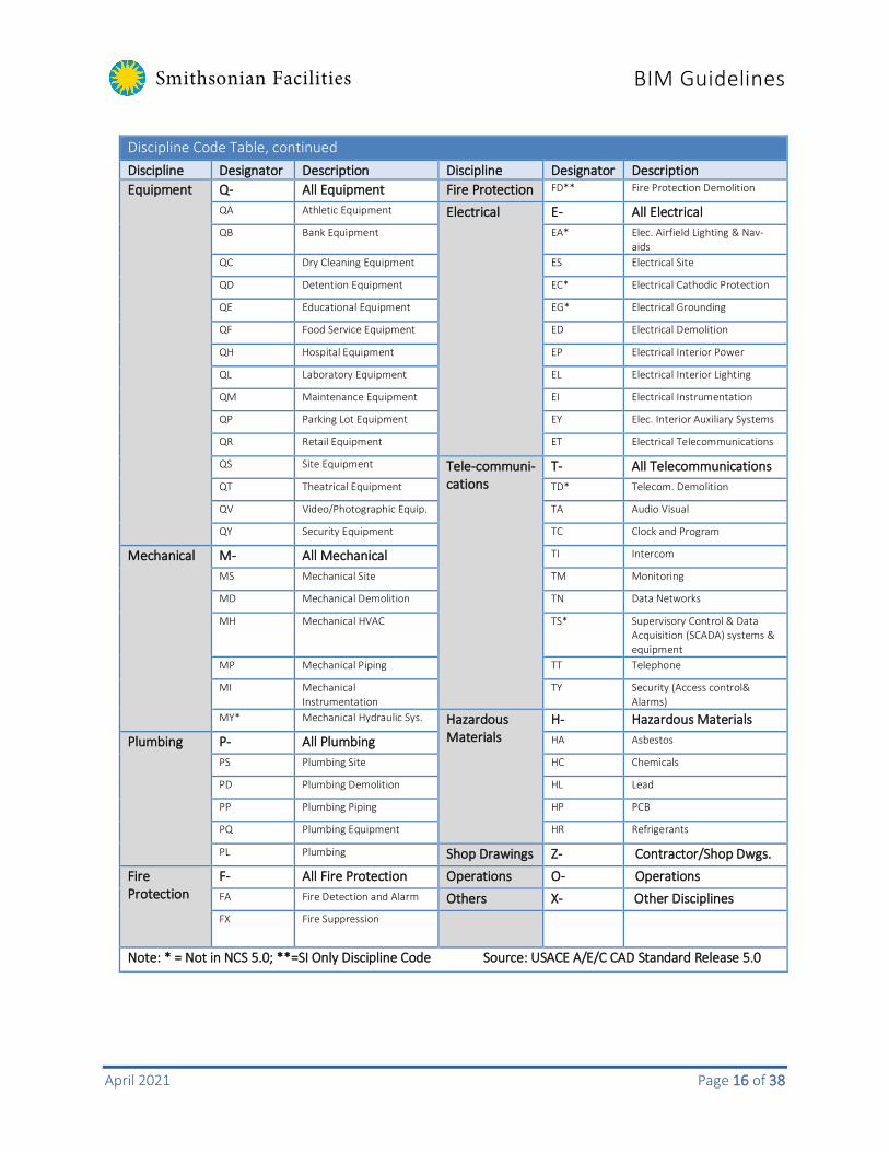
Discipline Code Table, continued Discipline Designator Description Discipline Designator Description Equipment
Q- All Equipment Fire Protection FD** Fire Protection Demolition
QA Athletic Equipment Electrical
E- All Electrical QB Bank Equipment EA* Elec. Airfield Lighting & Nav-
aids QC Dry Cleaning Equipment ES Electrical Site
QD Detention Equipment EC* Electrical Cathodic Protection
QE Educational Equipment EG* Electrical Grounding
QF Food Service Equipment ED Electrical Demolition
QH Hospital Equipment EP Electrical Interior Power
QL Laboratory Equipment EL Electrical Interior Lighting
QM Maintenance Equipment EI Electrical Instrumentation
QP Parking Lot Equipment EY Elec. Interior Auxiliary Systems
QR Retail Equipment ET Electrical Telecommunications
QS Site Equipment Tele-communi-cations
T- All Telecommunications QT Theatrical Equipment TD* Telecom. Demolition
QV Video/Photographic Equip. TA Audio Visual
QY Security Equipment TC Clock and Program
Mechanical
M- All Mechanical TI Intercom
MS Mechanical Site TM Monitoring
MD Mechanical Demolition TN Data Networks
MH Mechanical HVAC TS* Supervisory Control & Data Acquisition (SCADA) systems & equipment
MP Mechanical Piping TT Telephone
MI Mechanical Instrumentation
TY Security (Access control& Alarms)
MY* Mechanical Hydraulic Sys. Hazardous Materials
H- Hazardous Materials Plumbing
P- All Plumbing HA Asbestos
PS Plumbing Site HC Chemicals
PD Plumbing Demolition HL Lead
PP Plumbing Piping HP PCB
PQ Plumbing Equipment HR Refrigerants
PL Plumbing Shop Drawings Z- Contractor/Shop Dwgs. Fire Protection
F- All Fire Protection Operations O- Operations FA Fire Detection and Alarm Others X- Other Disciplines
FX Fire Suppression
Note: * = Not in NCS 5.0; **=SI Only Discipline Code Source: USACE A/E/C CAD Standard Release 5.0
Smithsonian Facilities BIM Guidelines
April 2021 Page 17 of 38
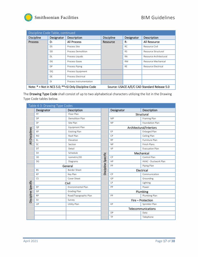
Discipline Code Table, continued Discipline Designator Description Discipline Designator Description Process
D- All Process Resource R- All Resource DS Process Site RC Resource Civil
DD Process Demolition RS Resource Structural
DL Process Liquids RA Resource Architectural
DG Process Gases RM Resource Mechanical
DP Process Piping RE Resource Electrical
DQ Process Equipment
DE Process Electrical
DI Process Instrumentation
Note: * = Not in NCS 5.0; **=SI Only Discipline Code Source: USACE A/E/C CAD Standard Release 5.0
The Drawing Type Code shall consist of up to two alphabetical characters utilizing the list in the Drawing Type Code tables below.
Table 4-3: Drawing Type Codes
All D
iscip
lines
Designator Description
Disc
iplin
e Sp
ecifi
c
Designator Description FP Floor Plan Structural DP Demolition Plan MP Framing Plan
SP Site Plan NP Foundation Plan
QP Equipment Plan Architectural/Interiors XP Existing Plan EP Enlarged Plan
RO Roof Plan CP Ceiling Plan
EL Elevation RP Furniture Plan
SC Section NP Finish Plans
DT Detail VP Evacuation Plan
SH Schedule Mechanical 3D Isometric/3D CP Control Plan
DG Diagrams HP HVAC - Ductwork Plan
Disc
iplin
e Sp
ecifi
c
General PP Piping Plan
BS Border Sheet Electrical KP Key Plan CP Communication
CS Cover Sheet GP Grounding
Civil LP Lighting
EP Environmental Plan PP Power
GP Grading Plan Plumbing RP Road/Topographic Plan PP Plumbing Plan
SV Survey Fire – Protection UP Utility Plan KP Sprinkler Plan
Telecommunications DP Data
TP Telephone

Smithsonian Facilities BIM Guidelines
April 2021 Page 18 of 38
It is important that files are named in this exact format to avoid system conflicts when drawings are transferred to the SI’s archival system. The sheet sequence number shall consist of three numerical characters from the following table:
Table 4-4: Sheet Sequence Numbers
000 General (Symbols, Legends, Notes) 500 Details
100 Plans (including Reflected Ceiling Plans) 600 Schedules and Diagrams
200 Elevations 700 User Defined (Elevators and Stair plans, details, sections)
300 Sections 800 User Defined (non-architecture)
400 Enlarged Views (plans, sections, elevations) 900 3D Views, Interior Details, Partition Types, Window Types
SF Combined PDF Naming
The A/E lead shall define the naming conventions for combined PDF volumes in accordance with the following format:
Format [File Name]- [-][Reference Date or Submission Type][-][Smithsonian Facilities Project Number][.][FileType]
Example Vol#_Report-65DD-1234567.PDF / Vol#_Drawing-140627-1234567.PDF
Table 4-5: Components of the Combined PDF file name
File name component Description File name Volume number description Reference date YYMMDD Submission type 35DD, 65DD, 100CD Project number The consultant team shall confirm the official project number with the SF
to establish project naming conventions. File type
Portable Document Format (.PDF)
Note: The BIM PxP should outline naming conventions for all the submittals pertaining to the project. Any deviations from the SF BIM Guidelines should be approved by the SI project COTR.

Smithsonian Facilities BIM Guidelines
April 2021 Page 19 of 38
4.2 Federated Model File Coordination The files that are generated by the consulting construction manager and trade contractors during the coordination process should follow the same naming conventions as described in the model file naming and sheet file naming sections.
The contractor shall require subcontractors, fabricators, suppliers, and manufactures to submit all models to the contractor utilizing 3D modeling software in order to facilitate seamless coordination with BIM workflows and file integration. All design elements should be produced three-dimensionally in programs that can output file formats supported by Autodesk Navisworks. Models should be updated after each project coordination meeting or as changes occur in the field during construction and delivered to SI at each project BIM milestone.
4.3 Electronic File Storage Refer to the project Scope of Work (SOW) to determine which type of transmission method is required for each project submission.
FTP Site: Due to the constraints of sending large files via e-mail, OCIO has established an FTP site to use for transferring electronic documents between Smithsonian Facilities and outside consultants. The FTP site acts like any other folder in Windows Explorer. To access the site please obtain instructions from the project design manager.
Note: To prevent unauthorized use of SI files, any files left on the FTP site for more than 48 hours will be deleted. This should give everyone ample time to send and receive daily work. Please make sure you have copies of your files stored on your personal computer or on the secure internal network.
E-mail: The size of attachments to e-mails on the Smithsonian network is limited to 3.5 megabytes, total. Use of the FTP site is recommended for larger transmissions.
Dropbox: SI utilizes Dropbox for the transfer of large files. Please discuss with the Project Design Manager to obtain shared folder access.
OneDrive: SI utilizes OneDrive for the transfer of large files. Please discuss with the Project Design Manager to obtain shared folder access.
Documentation:
The Smithsonian Facilities Project Documentation Form and Deliverables Matrix. These forms are similar in nature to the GSA’s deliverable requirements. The Project Documentation Form identifies the personnel responsible for the project, versions of software used in its preparation, and any script files, non-AutoCAD entities (fonts, line types, blocks, etc.) used in drawing preparation. The Deliverables Matrix identifies each drawing submitted by name, all external references by name, and the plot scale for each drawing. Refer to Appendix A in this document for examples of the forms.
Smithsonian Facilities BIM Guidelines
April 2021 Page 20 of 38
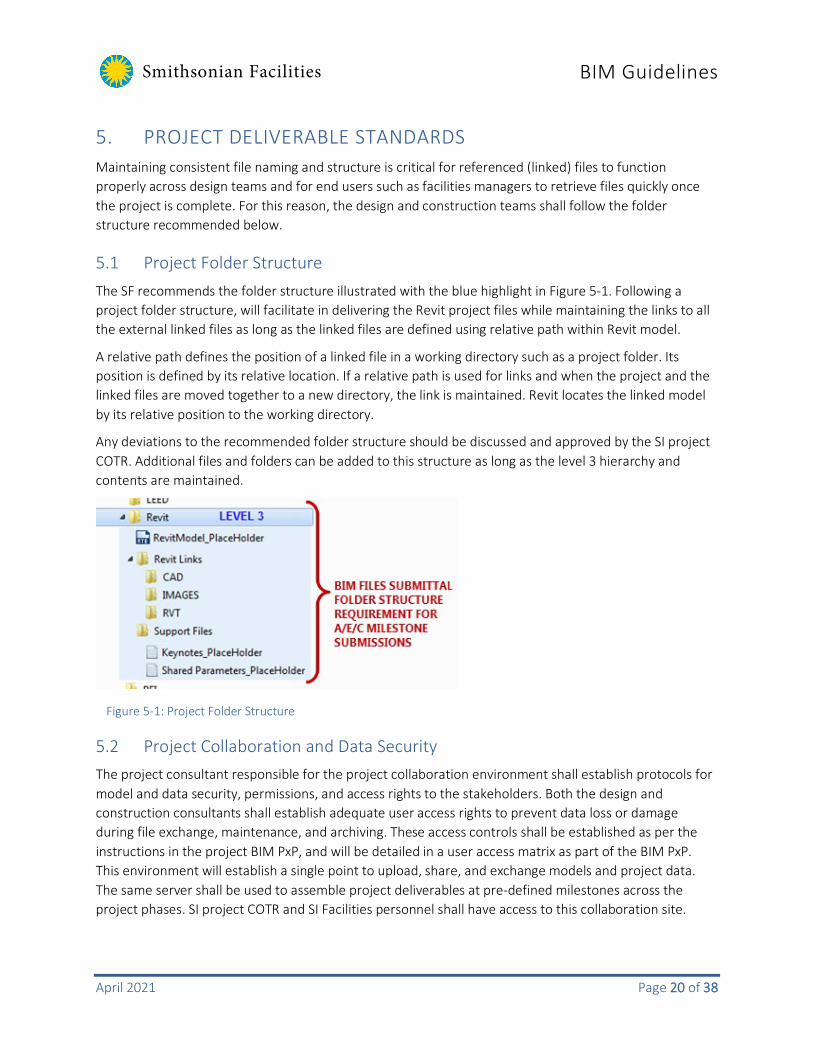
5. PROJECT DELIVERABLE STANDARDS Maintaining consistent file naming and structure is critical for referenced (linked) files to function properly across design teams and for end users such as facilities managers to retrieve files quickly once the project is complete. For this reason, the design and construction teams shall follow the folder structure recommended below.
5.1 Project Folder Structure The SF recommends the folder structure illustrated with the blue highlight in Figure 5-1. Following a project folder structure, will facilitate in delivering the Revit project files while maintaining the links to all the external linked files as long as the linked files are defined using relative path within Revit model.
A relative path defines the position of a linked file in a working directory such as a project folder. Its position is defined by its relative location. If a relative path is used for links and when the project and the linked files are moved together to a new directory, the link is maintained. Revit locates the linked model by its relative position to the working directory.
Any deviations to the recommended folder structure should be discussed and approved by the SI project COTR. Additional files and folders can be added to this structure as long as the level 3 hierarchy and contents are maintained.
5.2 Project Collaboration and Data Security The project consultant responsible for the project collaboration environment shall establish protocols for model and data security, permissions, and access rights to the stakeholders. Both the design and construction consultants shall establish adequate user access rights to prevent data loss or damage during file exchange, maintenance, and archiving. These access controls shall be established as per the instructions in the project BIM PxP, and will be detailed in a user access matrix as part of the BIM PxP. This environment will establish a single point to upload, share, and exchange models and project data. The same server shall be used to assemble project deliverables at pre-defined milestones across the project phases. SI project COTR and SI Facilities personnel shall have access to this collaboration site.
Figure 5-1: Project Folder Structure

Smithsonian Facilities BIM Guidelines
April 2021 Page 21 of 38
5.3 BIM Deliverables Project BIM requirements are defined within a project’s scope of work (SOW) and will vary between projects. A suggested framework for BIM deliverables is provided below, organized by standard SI project milestones.
The level of development (LOD) and level of accuracy (LOA) for each BIM deliverable should be listed in the project’s SF BIM content matrix and BIM PxP. LOD and LOA should be sufficient to produce traditional two-dimensional deliverables required for each stage.
The specific BIM deliverable requirements for a project along with and responsible parties will be listed by model category, and be described in the project BIM PxP.
Design
Pre-Design
• BIM Project Execution Plan (within 30 days after contract execution)
• Feasibility Models*
• Database of Programs/Spaces
• Massing/Volume/Area
• Relationships/Functions
• Responsibility Matrix • Data Organization Outline
• Restatement of Owner Requirements
• AIA E202 Refinements
• Laser Scan Files* (Point Clouds)
• Existing Conditions Model(s)*
• SF Facility Asset Data Spreadsheet
Schematic Design (35% Submission)
• BIM Execution Plan Update • Preliminary Energy Model Values* 1
• Concept Model
• Architectural Model - Based on approved concept model in the native BIM format
• Preliminary Systems Model - Structural, MEP, Civil or other systems required by the project in the native BIM format
• Clash Detection Report
• IFC models for all the required disciplines
• Navisworks files (If used for Clash Detection)
• SF Facility Asset Data Spreadsheet
Design Development (65% Submission)

Smithsonian Facilities BIM Guidelines
April 2021 Page 22 of 38
• BIM Project Execution Plan
• Energy Model Values*1
• Architectural Model in the native BIM format
• Structural Model in the native BIM format
• MEP Model in the native BIM format
• Fire Protection Model in the native BIM format
• Life safety and security model in the native BIM format
• Site/civil model in the native CAD format
• Other systems models* in the native BIM format • Detailed clash/collision report
• Code/model review report*
• IFC models for all the required disciplines
• Navisworks files (If used for Clash Detection)
• SI-GIS Exports (CAD and Excel Format)
• SF Facility Asset Data Spreadsheet
Construction Documents (100% and Final Submission)
• BIM Project Execution Plan
• Energy model values*1 • Architectural model in the native BIM format
• Structural model in the native BIM format
• MEP model in the native BIM format
• Fire protection model in the native BIM format
• Life safety and security model in the native BIM format
• Site/civil model in the native CAD format
• Other systems models* in the native BIM format
• Detailed clash/collision report - showing issues and resolutions
• Code/model review report* • Quantity reports*
• IFC models for all the required disciplines
• Navisworks files (If used for Clash Detection)
• SI-GIS Exports (CAD and Excel Format)
• SF Facility Asset Data Spreadsheet
At the 100% Construction Documents submission, the design team shall be responsible for providing:
• A federated BIM fully coordinated and assembled into one Revit Black Box View. • Separate copies of each technical discipline model in the original software authoring tool and IFC
format.

Smithsonian Facilities BIM Guidelines
April 2021 Page 23 of 38
• A 2D plan set, derived from the assembled BIM, for contract bidding in the CAD and PDF formats.
________
* If applicable/available/required 1 Energy models may be executed within applications existing BIM software and applications.

Smithsonian Facilities BIM Guidelines
April 2021 Page 24 of 38
The table below lists a project’s electronic deliverables for design phase.
Table 5-1: Design Deliverables
Phase Submission Requirements Format
Programming Narrative Project Execution Plan Existing Condition Model(s) SI Facility Asset Data Spreadsheet
.pdf, .docx
.rvt, .dwg, .ifc, point cloud formats
.rcs/.rcp/.pcg/.pts/.ptx/.dp/.las, .laz,.xyz, etc. .xlsx
Schematic Design (35% Submission)
Narrative Project Execution Plan Drawings Design Intent Model(s) SI Facility Asset Data Spreadsheet
.pdf, .docx
.rvt, .ifc, .nwc, .nwd, .dwg
.xlsx
Design Development (65% Submission)
Project Execution Plan LOD Matirx Specifications Drawings Design Intent Model SI-GIS Exports SI Facility Asset Data Spreadsheet
.pdf, docx
.pdf, .docx
.rvt, .ifc, .nwc, .nwd, .dwg .dwg, .xlsx .xlsx
Construction Documents (100% Submission)
Project Execution Plan LOD Matrix Drawings Specifications Design Intent Model SI-GIS Exports SI Facility Asset Data Spreadsheet
.pdf, .docx
.pdf, xlsx
.pdf, .dwg
.pdf, .docx
.rvt, .ifc, .nwc, .nwd, .dwg
.dwg, .xlsx
.xlsx
100% Construction Documents (Back Check Submission)
Project Execution Plan LOD Matrix Drawings Specifications Design Intent Model SI-GIS Exports
.pdf, .docx
.pdf, .xlsx
.pdf, .dwg
.pdf, .docx
.rvt, .ifc, , .nwc, .nwd, .dwg
.dwg, .xlsx

Smithsonian Facilities BIM Guidelines
April 2021 Page 25 of 38
Table 5-1: Design Deliverables
Phase Submission Requirements Format
SI Facility Asset Data Spreadsheet
.xlsx
Bid Process Addenda .pdf, .rvt, .dwg, .ifc
Construction Bulletins .pdf, .rvt, .ifc, .nwc, .nwd, .dwg
Record Documents Project Execution Plan LOD Matirx Specifications Conformed Model(s) SI-GIS Exports Drawings
.pdf, .docx
.pdf, .xlsx
.pdf, .docx
.rvt, .ifc, .nwc, .nwd, .dwg
.dwg, .xlsx
.pdf, .dwg
Construction
The construction model(s), coordination model(s), coordination reports, and facility data for the project will be submitted by the contractor to the SI during the construction phase according to the project scope of work.
Refer to the project-specific document “01 3250_BIM Reqs” for more specificity about construction phase and as-built BIM requirements.
Table 5-3 Construction Deliverables
Phase Submission Requirements Format
Construction (Monthly) Coordination Model(s) SF Facility Asset Data Spreadsheet
.rvt, .ifc,. nwc, .nwd, .dwg .xlsx
Construction (Quarterly) Construction Model(s) SF Facility Asset Data Spreadsheet
.rvt, .ifc, .nwc, .nwd, .dwg
.xlsx
At project completion – with submittals, O&M’s and warranties attached
As-Built Model – Final Project Execution Plan LOD Matrix O&M and Warranty Documents SI-GIS Exports SF Facility Asset Data Spreadsheet
.rvt, .dwg, .ifc, .nwc, .nwd
.pdf, .docx
.pdf, .xlsx
.pdf, .docx
.dwg, .xlsx
.xlsx

Smithsonian Facilities BIM Guidelines
April 2021 Page 26 of 38
Final Deliverables/As-Built Documentation
At project completion, the project consultant, typically the Contractor, will update and submit As-Built Model(s) to document the condition of the facility upon completion of construction. As-Built Model(s) are to be submitted with all Model(s) link into one central model using Autodesk Revit. In addition the contractor shall submit final SF Facility Asset Data Spreadsheet, LOD Matrix, BIM PxP, O&M manuals CAD exports, SI-GIS exports and warranty documents with final model.
5.4 Autodesk Revit BIM Deliverables Checklist
Table 5-2: BIM Deliverable Checklist
Description / Model file name conforms to SF standards All annotations and title blocks are as per the SF standards All SI floor plans and area plan views required by the SF have been created for all floors in the project All the custom SI schedules are populated with all the required data for the project The model is correctly assembled as per visual inspection All the model contents are correctly placed per their element categorization in the correct workset, and conform to standards All non-transmittal linked-in files (CAD/Revit) have been removed from the model All non-required views / legends / schedules / sheets / images have been removed from the model Unwanted Design Options have been removed from the model All unnecessary groups have been removed from the model. All groups used to model the building have been ungrouped and purged from the deliverables to reduce the file size of the model
As a last step, the model has been purged (repeat the process three times -- materials are only removed after the parent object has been removed). This will reduce the file size. Update Save to Central view with any relevant model notes

Smithsonian Facilities BIM Guidelines
April 2021 Page 27 of 38
5.5 CAD Deliverables from BIM
Sheet Drawing Submission Standards
Introduction
CAD files exported from the project BIM represent one, and only one, plotted drawing sheet. There must be a one-to-one relationship between files and floors.
Areas of a floor that occur at different elevations relative to each other, without overlapping, should be in the same drawing. Areas that occur as mezzanines, no matter how small, should be relegated to a separate drawing, with the full building column grid included to help with spatial reference.
File Format
All drawing sheets shall be submitted in both Adobe Acrobat PDF file format (.pdf) and in AutoCAD (.dwg) format.
PDF Files
All graphics in PDF files must be measurable/snap-able using software markup tools such as Adobe Acrobat Professional or Bluebeam. All drawing text in PDF files must be searchable. There shall be one PDF file per printed sheet in the drawing set.
Recent versions of the Adobe Acrobat application allow for the inclusion of layers from AutoCAD files in the PDF document. Use of this feature will NOT be accepted.
AutoCAD
Drawing files shall be in the AutoCAD (.dwg) format. The version of the software will be as noted in the project BIM PxP.
There shall be one AutoCAD (.dwg) file per printed sheet in the set, and X-refs shall be bound.
CAD Page Setup
Pages must be oriented, when displayed on-screen, in the same direction as the hard copy would be read.
Scale
All 2D PDF files must be created on the paper size used for the contract documents. When printed on the appropriately sized paper, all drawing scales shown in the drawing should be accurate when measured with mechanical drafting tools.
Line Weights
Acceptable line weights on drawing deliverables will be in a range from about 0.18 mm to 1.0 mm when plotted full-size.
Only use the highest range of line weights to indicate major dividing lines such as section-cuts and match lines.
The narrowest line weights should be used for highly detailed items and column grids.

Smithsonian Facilities BIM Guidelines
April 2021 Page 28 of 38
Within the middle-range, be sure to giving greater weight to new construction when occupying the same plan as existing construction. Give even greater weight to annotations.
On engineering drawings referencing the partitions, ceiling grids, and other components on the architectural plans, a 50% to 75% shading should be used on the architectural elements to increase the readability of the engineering elements.
Layers
Layer names must adhere to the most recent version of the AIA Layer Guidelines, as included in the National CAD Standard.
Building elements must be placed on the correct layers. Do not repeat similar information among different layers.
Do not store information on Layer "0".
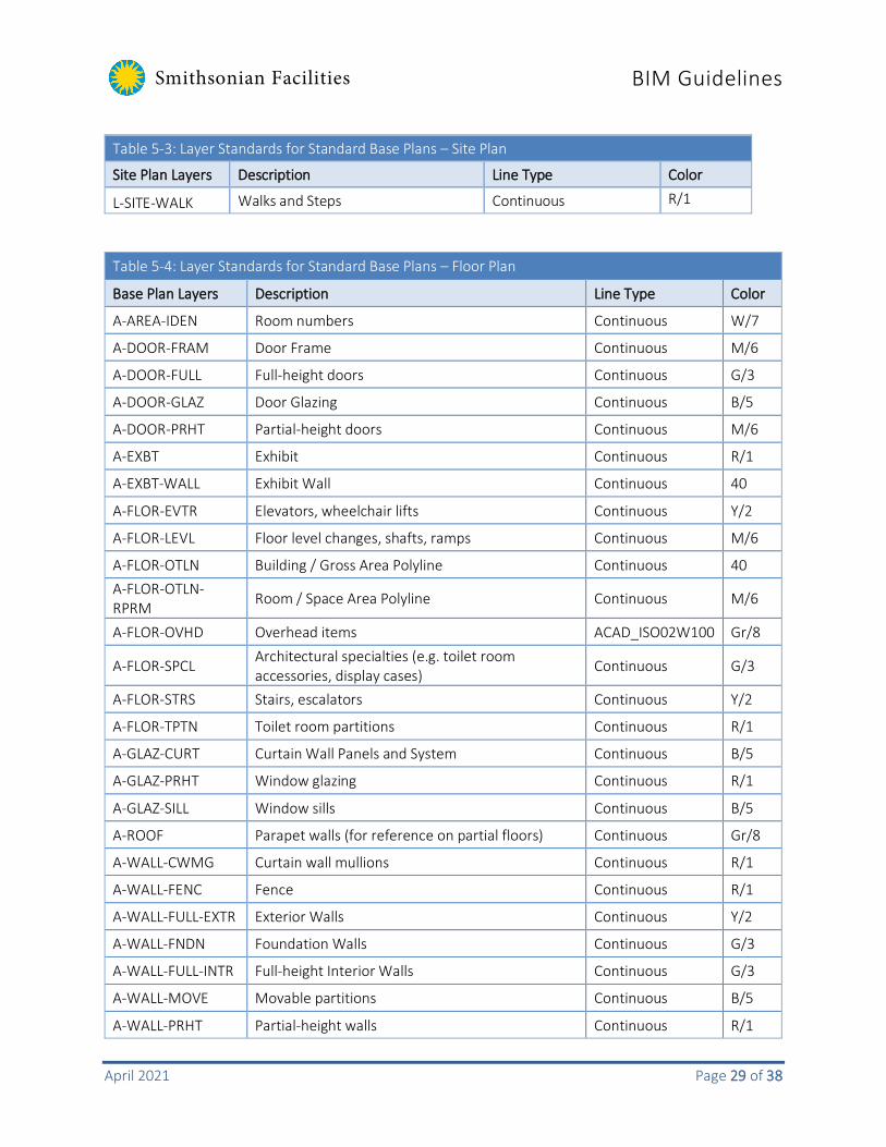
The following charts list the layers for site plans and floor plans that are considered the Standard Base Plans. Only these layers are required to meet the specifications of this section.
Table 5-3: Layer Standards for Standard Base Plans – Site Plan
Site Plan Layers Description Line Type Color
C-BLDG-OTLN Building Footprints Continuous W/7
C-PKNG-OTLN Parking Lots Continuous C/4
C-PKNG-CURB Parking Curbs and Gutters Continuous G/3
C-PROP-LINE Property Lines (check Benchmarks) Continuous Y/2
C-ROAD-OTLN Roads Continuous C/4
C-ROAD-CURB Curbs Continuous M/6
L-PLNT-TREE Trees Continuous 83
L-PLNT-GRND Ground Covers and Vines Continuous 82
L-PLNT-BEDS Landscaping Beds Continuous M/6
L-PLNT-BUSH Bushes and Shrubs Continuous 83
L-PLNT-TURF Lawn Areas Continuous 23
L-SITE-BRDG Bridges Continuous 22
L-SITE-EWAT Water features Continuous 162
L-SITE-FENC Fencing Continuous Y/2
L-SITE-DECK Decks Continuous 232
L-SITE-POOL Pools and Spas Continuous 162
L-SITE-ROCK Boulders and cobble Continuous R/1
L-SITE-RTWL Retaining Walls Continuous C/4
L-SITE-SPRT Sports Fields Continuous Y/2
Smithsonian Facilities BIM Guidelines
April 2021 Page 29 of 38
Table 5-3: Layer Standards for Standard Base Plans – Site Plan
Site Plan Layers Description Line Type Color
L-SITE-WALK Walks and Steps Continuous R/1
Table 5-4: Layer Standards for Standard Base Plans – Floor Plan
Base Plan Layers Description Line Type Color
A-AREA-IDEN Room numbers Continuous W/7
A-DOOR-FRAM Door Frame Continuous M/6
A-DOOR-FULL Full-height doors Continuous G/3
A-DOOR-GLAZ Door Glazing Continuous B/5
A-DOOR-PRHT Partial-height doors Continuous M/6
A-EXBT Exhibit Continuous R/1
A-EXBT-WALL Exhibit Wall Continuous 40
A-FLOR-EVTR Elevators, wheelchair lifts Continuous Y/2
A-FLOR-LEVL Floor level changes, shafts, ramps Continuous M/6
A-FLOR-OTLN Building / Gross Area Polyline Continuous 40 A-FLOR-OTLN-RPRM Room / Space Area Polyline Continuous M/6
A-FLOR-OVHD Overhead items ACAD_ISO02W100 Gr/8
A-FLOR-SPCL Architectural specialties (e.g. toilet room accessories, display cases) Continuous G/3
A-FLOR-STRS Stairs, escalators Continuous Y/2
A-FLOR-TPTN Toilet room partitions Continuous R/1
A-GLAZ-CURT Curtain Wall Panels and System Continuous B/5
A-GLAZ-PRHT Window glazing Continuous R/1
A-GLAZ-SILL Window sills Continuous B/5
A-ROOF Parapet walls (for reference on partial floors) Continuous Gr/8
A-WALL-CWMG Curtain wall mullions Continuous R/1
A-WALL-FENC Fence Continuous R/1
A-WALL-FULL-EXTR Exterior Walls Continuous Y/2
A-WALL-FNDN Foundation Walls Continuous G/3
A-WALL-FULL-INTR Full-height Interior Walls Continuous G/3
A-WALL-MOVE Movable partitions Continuous B/5
A-WALL-PRHT Partial-height walls Continuous R/1

Smithsonian Facilities BIM Guidelines
April 2021 Page 30 of 38
Table 5-4: Layer Standards for Standard Base Plans – Floor Plan
Base Plan Layers Description Line Type Color
S-COLS-PRIM Primary columns Continuous M/6
S-COLS-SCND Secondary columns Continuous Y/2
A-AREA-LINE Lines defining room areas that are not walls Continuous C/4
P-SANR-FIXT Plumbing Fixtures Continuous M/6
A-FLOR-HRAL Handrails Continuous R/1
A-FLOR-WDWK Built-in cabinets and counters Continuous G/3
A-WALL-HEAD Door headers Continuous R/1
I-FURN Furniture Continuous B/5
I-FURN-PNLS Systems Furniture Continuous B/5
S-GRID-HORZ Horizontal column grid lines ACAD_ISO08W100 B/5
S-GRID-IDEN Column identifiers Continuous R/1
S-GRID-VERT Vertical column grid lines ACAD_ISO08W100 B/5
Standard Title Block and Cover Sheet
The standard Smithsonian title block shall be used on every sheet. The first sheet in any set of drawings (cover sheet) shall be designated the Title / Cover Sheet, and will be numbered according to the process outlined in the previous section. It shall contain the OFEO approval block directly above the title block.
CAD Project Title Block
All of the title block parameters are block attributes. To edit the attributes, use AutoCAD’s DDATTE or AT command. Do not change the text size in the drawing provided (except for the A/E logo and information pertinent to consultants).
Please refer to the Special Conditions for A/E Services document for logo location and size, as well as the identification code.
All Smithsonian title blocks are available for download at the OFEO website, A/E Center, in DWG format.
Revit Project Title Block
The Smithsonian Institution’s Revit project title block contains parameters for project information compliant with the SF CAD guidelines. There are two sizes of SI title blocks within the SF Revit Templates: SI-24x36In and SI-36x48In.
See Revit Template User Guide for additional Information.

Smithsonian Facilities BIM Guidelines
April 2021 Page 31 of 38
SI Sheet Sizes
The following table lists sheet sizes to be used for all SF projects. The preferred standard is Arch D (24 x 36 in). This sheet size (Revit title block family) is provided in the SF Revit Templates, along with Arch E (36 x 48 in.). If a project requires an alternate size, approval must be obtained from the SI project COTR. Revit title blocks and cover sheet families should be created by A/E for the sizes that are not provided in the SF Revit Template, as per the respective size sheet and coversheet files in “dwg” format.
To create the new title block and cover sheet families, the A/E shall use the Revit parameters and symbols from the Revit title block and cover sheet families provided within the SF Revit Templates. All title blocks and cover sheets are provided in metric and imperial versions, and are available for download at the SI A/E Center web site in “dwg” format. All drawings in a project submission shall be produced in a consistent format and drawing size. Submitted sketches should utilize either the letter or tabloid format.
Table 5-5: SI Sheet Sizes
Paper Size Dimensions File Name Arch D (Standard) 24 by 36 inches 610 by 914 mm Cover: ST-CVR_in.dwg Sheet: ST-
TTL_in.dwg Cover: ST-CVR_mm.dwg Sheet: ST-
Arch E 36 by 48 inches 914 by 1219 mm Cover: E-CVR_in.dwg Sheet: E-TTL_in.dwg Cover: E-CVR_mm.dwg Sheet: E-
Arch F (Arch 30) 30 by 42 inches 762 by 1067 mm Cover: F-CVR_in.dwg Sheet: F-TTL_in.dwg Cover: F-CVR_mm.dwg Sheet: F-
Tabloid 11 by 17 inches 279 by 432 mm
Vertical: 11x17-V_in.dwg Horizontal: 11x17-H_in.dwg Vertical: 11x17-V_mm.dwg
Letter 8-1/2 by 11 inches 216 by 279 mm Portrait: 8x11-P_in.dwg Landscape: 8x11-L_in.dwg Portrait: 8x11-P_mm.dwg

Smithsonian Facilities BIM Guidelines
April 2021 Page 32 of 38
SF Project Units, Fonts and Dimensions
Project Units
Project units and design units must be configured during the initial stages of the project. The project units’ parameter within the SF Revit Template files is set to imperial units (feet/inches), however SF projects may require metric deliverables.
Metric Units
To change from imperial to metric units in Revit:
• Create a new Revit project file (.rvt) by loading the template file into a Revit work session, and save it with the appropriate file name for your project/facility
• On the Revit menu’s Manage tab -> Settings panel, select the Project Units option
• The Project Units dialog box pops-up. Click the button under the Format column for each unit type to display the Format settings dialog box
• In the Format dialog box, select the correct unit from the Units drop down list.
For additional notes and instructions on units’ conversion, refer to the Autodesk Revit Help web site.
Text Sizes and Fonts
The SF Revit Template includes SI standard fonts based upon the National CAD Standard v5 (NCS). Arial font is the standard for all SI text annotations (the SF does accepts AutoCAD text or true-type fonts). RomanS, Swis721 Blk BT and Minion fonts are also used in the title blocks and headings.
Minion Open-type fonts are available for download at https://logo.si.edu/visual-styles/typography/
The text size for typical notes within SI architectural drawings is 3mm (1/8”) with a 1.0 width factor. Any deviations must be approved by SF.
Upper-case lettering shall be used on drawings unless lower-case letters are required to conform to other established standards, equipment nomenclature, or marking.
Dimensions
The SI Revit Template includes the SI “soft metrics” dimensioning standard, which calls for dimensional representation of metric units followed by imperial units in the parenthesis. For additional information, see soft or hard metrics as described within DoD Publication SD-10 Guide for Identification and Development of Metric Standards.
Two types of SF standard tic-mark types are included in the SF Revit Templates: SI_Arrow and SI_Slash. Confirm the required dimensioning standard for the project with the SI, and modify if necessary.

Smithsonian Facilities BIM Guidelines
April 2021 Page 33 of 38
Symbols
SF BIM and CAD Annotation Symbols
Symbols included in the SF Revit Templates have been set up to comply with the SF CAD Standards. No substitutions will be permitted. (Images shown are not to scale).
Figure 5-2: Custom SF annotation symbols
Figure 5-3: Custom SF view title symbols

Smithsonian Facilities BIM Guidelines
April 2021 Page 34 of 38
Smithsonian Facilities CAD Standard Symbols
Figure 5-4: SF CAD symbols available from the Smithsonian Facilities A/E Center website
Smithsonian Facilities BIM Guidelines
April 2021 Page 35 of 38
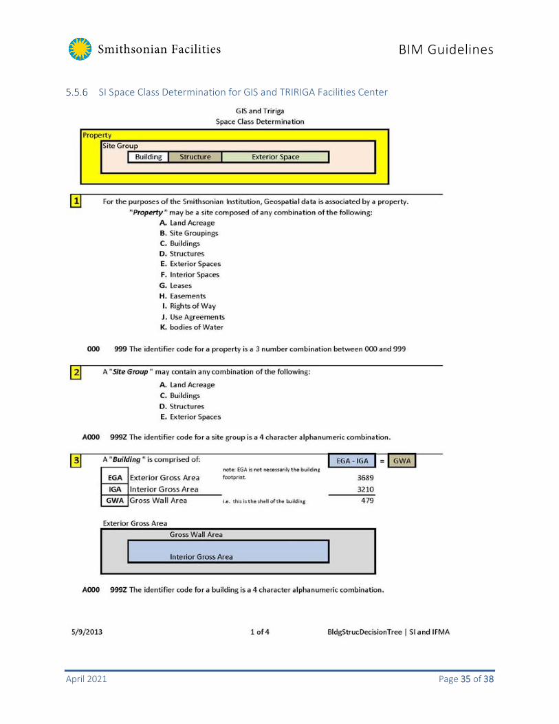
SI Space Class Determination for GIS and TRIRIGA Facilities Center
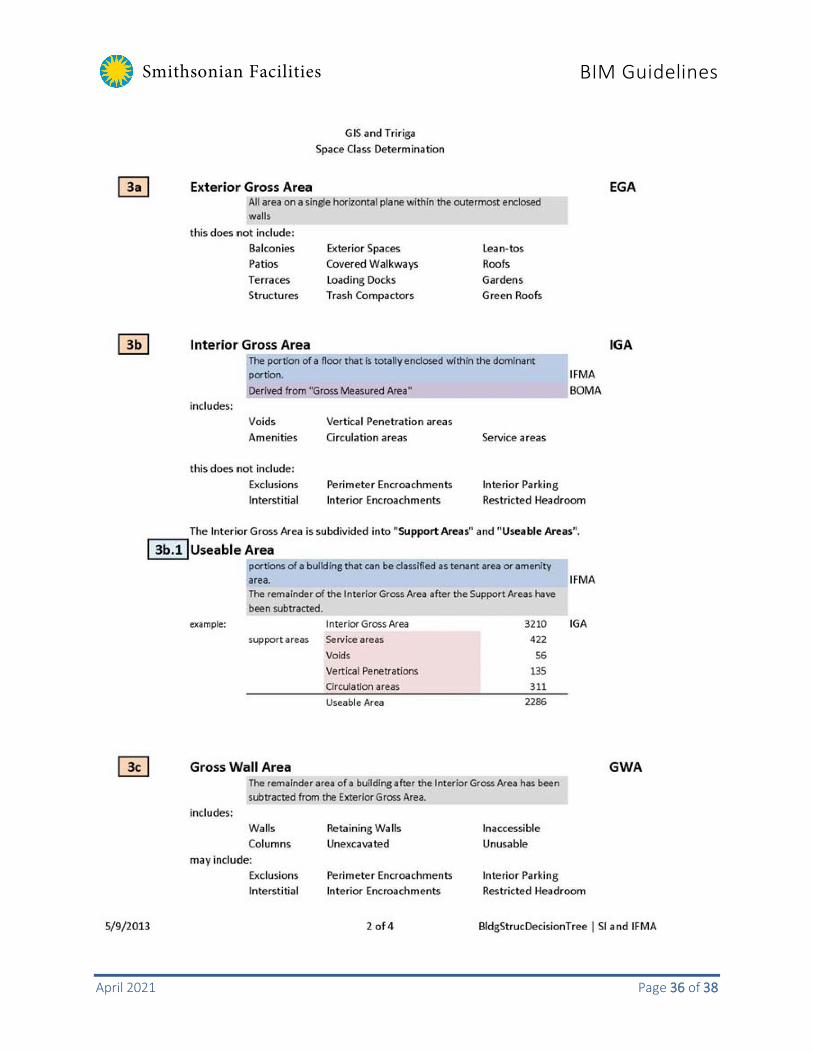
Smithsonian Facilities BIM Guidelines
April 2021 Page 36 of 38
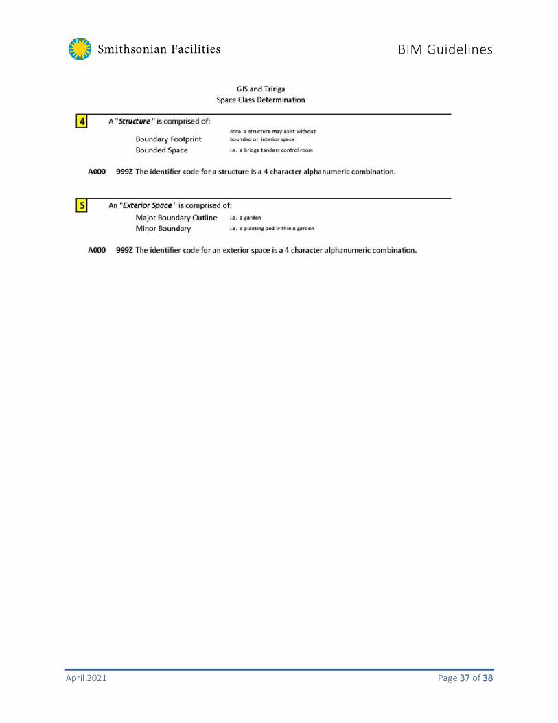
Smithsonian Facilities BIM Guidelines
April 2021 Page 37 of 38

Smithsonian Facilities BIM Guidelines
April 2021 Page 38 of 38
[End of Document]