Facilities CAD and BIM Guidelines
37
Facility Information Systems MIT Infrastructure Business Operations November 1 st , 2016 MIT Design Standards BIM and CAD Drawing Standards v6.0 Thematic Folder
Transcript of Facilities CAD and BIM Guidelines

Facility Information Systems MIT Infrastructure Business Operations November 1st, 2016
MIT Design Standards BIM and CAD Drawing Standards v6.0
Thematic Folder
MIT Design Standards | BIM and CAD Drawing Standards Thematic Folder Page 1 of 39
Table of Contents
1. INTRODUCTION ...................................................................................................... 2
1.1 RENOVATIONS AND SPACE CHANGE PROJECTS REQUIREMENTS ...................................................................... 2 1.2 CAPITAL PROJECTS REQUIREMENTS........................................................................................................... 3
2. CAD DRAWING PRODUCTION .............................................................................. 4
2.1 FILE FORMAT AND SETUP ................................................................................................................. 4 2.2 TITLE BLOCKS ....................................................................................................................................... 5 2.3 LAYERING ............................................................................................................................................ 7 2.4 TRANSLATING CAD FILES TO DWG FORMAT ............................................................................................ 24
3. USE OF BUILDING INFORMATION MODELING (BIM) ........................................ 25
3.1 MIT REQUIREMENTS ........................................................................................................................... 25 3.2 BIM EXECUTION PLAN ......................................................................................................................... 25 3.3 BIM STANDARDS ................................................................................................................................ 25 3.4 BIM MODELS AND DELIVERABLES .......................................................................................................... 26
4. ARCHIVAL PRINT FILES ...................................................................................... 26
4.1 PDF FILE CREATION ............................................................................................................................ 27 4.2 TIF FILE CREATION .............................................................................................................................. 28
5. FILE IDENTIFICATION AND NAMING CONVENTIONS ....................................... 28
5.1 DWG SHEET IDENTIFICATION ................................................................................................................ 28 5.2 FILE ORGANIZATION AND TRANSMITTAL TO MIT ....................................................................................... 30
APPENDIX A: BIM EXECUTION PLAN
APPENDIX B: GLOSSARY OF TERMS
APPENDIX C: ELECTRONIC FILE INDEX

MIT Design Standards | BIM and CAD Drawing Standards Thematic Folder Page 2 of 39
1. INTRODUCTION
These guidelines are issued to promote the development of electronic drawings and models suitable for use in the MIT Department of Facilities CAD and BIM environment. Consistency and compatibility with existing MIT documents can only be achieved when these standards are strictly adhered to. Electronic drawings produced and submitted in accordance with these standards have significantly greater value to the Institute. Architects, Engineers and Contractors delivering documentation to MIT must ensure these standards are reviewed, understood and followed by those people responsible for preparing electronic drawings and models.
Each of the following sections contains the most essential criteria for developing electronic drawings and models for use in the MIT CAD and BIM environment.
1.1 Renovations and Space Change Projects Requirements
For typical Renovation and Space Change projects, the Designer is responsible for submitting a complete set of construction documents (CDs) to MIT prior to the beginning of construction. During construction, the Contractors are responsible for submitting complete As-Built documentation to the project team as described in their contracts in electronic format and Designers are responsible for submitting the record documents to MIT based on this As-Built documentation. Construction Documents and Record Documents submitted to MIT need to adhere the criteria outlined in this document.
Designers that are not familiar with MIT's CAD requirements should meet jointly with the MIT Project Manager and representatives from MIT’s Facility Information Systems (FIS) to discuss specific project requirements prior to the development of any CAD documentation. Designers should also take this opportunity to relay the project scope to FIS so MIT can furnish Designer with existing drawings that will benefit the design team.
Milestone Deliverables: 1. For typical Renovation and Space Change projects, the following documentation
shall be delivered to MIT at the following project milestones:
Design: When the project is in the end of design phase, the Designer shall submit a complete set of Design Documents (100% DD) in electronic and hard copy format to MIT. These documents will be archived as a record of the project and will also be used for initial room numbering purposes. Please refer to the MIT Space Accounting Guidelines for information about the room numbering process.
Construction: When the project enters the construction phase, the Designer shall submit a complete set of 100% Construction Documents (100% CD) in electronic
MIT Design Standards | BIM and CAD Drawing Standards Thematic Folder Page 3 of 39
and hard copy format to MIT. These files will be archived as a record of the project and will be used for room numbering verification. Please refer to the MIT Space Accounting Guidelines for information about updating room numbers during the construction process.
Completion: When the project has been completed, the Contractors shall submit a complete set of As-Built (AB) Documents to the project team as described in their contracts (electronic format). Designers are to submit the Record Drawings based on these As-Builts and need to meet the format requirements outlined in this document.
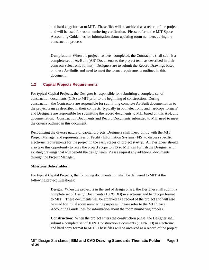
1.2 Capital Projects Requirements
For typical Capital Projects, the Designer is responsible for submitting a complete set of construction documents (CDs) to MIT prior to the beginning of construction. During construction, the Contractors are responsible for submitting complete As-Built documentation to the project team as described in their contracts (typically in both electronic and hardcopy formats) and Designers are responsible for submitting the record documents to MIT based on this As-Built documentation. Construction Documents and Record Documents submitted to MIT need to meet the criteria outlined in this document.
Recognizing the diverse nature of capital projects, Designers shall meet jointly with the MIT Project Manager and representatives of Facility Information Systems (FIS) to discuss specific electronic requirements for the project in the early stages of project startup. All Designers should also take this opportunity to relay the project scope to FIS so MIT can furnish the Designer with existing drawings that will benefit the design team. Please request any additional documents through the Project Manager.
Milestone Deliverables:
For typical Capital Projects, the following documentation shall be delivered to MIT at the following project milestones:
Design: When the project is in the end of design phase, the Designer shall submit a complete set of Design Documents (100% DD) in electronic and hard copy format to MIT. These documents will be archived as a record of the project and will also be used for initial room numbering purposes. Please refer to the MIT Space Accounting Guidelines for information about the room numbering process.
Construction: When the project enters the construction phase, the Designer shall submit a complete set of 100% Construction Documents (100% CD) in electronic and hard copy format to MIT. These files will be archived as a record of the project
MIT Design Standards | BIM and CAD Drawing Standards Thematic Folder Page 4 of 39
and will be used for room numbering verification. Please refer to the MIT Space Accounting Guidelines for information about updating room numbers during the construction process.
Completion: When the project has been completed, the Contractors shall submit a complete set of As-Built (AB) Documents to the project team as described in their contracts (typically in electronic and hardcopy formats). Designers are to submit the Record Drawings based on these As-Builts and need to meet the format requirements outlined in this document.
2. CAD DRAWING PRODUCTION
2.1 File Format and Setup
Electronic File Format:
Construction and Record Document project drawings must be submitted in the file formats listed below; other formats are not acceptable without the prior consent of MIT’s Facility Information Systems (FIS).
a) AutoCAD® 2013 – DWG format only. b) Revit® 2013 – RVT format only c) Adobe® PDF version 6.0 or higher. d) TIF 6.0
Scale, Units, and Tolerances:
1. All CAD drawing models shall be drafted at full scale in architectural units, such that one drawing unit equals one inch. Tolerances for CD’s are implicit within professional service contracts.
Fonts and Text Styles:
1. Drawings created using non-standard AutoCAD® fonts, linetypes, and hatch patterns can result in content discrepancies in the delivered drawing set. To ensure the integrity of the drawing set and minimize potential problems:
a. Only native AutoCAD® fonts, linetypes and hatch patterns are to be used. These are standard support features installed as part of a standard AutoCAD® installation.
b. Custom fonts, linetypes and hatch patterns, including those provided by 3rd party software, shall not be used.
c. Only these TrueType fonts shall be used: Arial, Courier New, Times New Roman. d. Postscript fonts are not to be used.

MIT Design Standards | BIM and CAD Drawing Standards Thematic Folder Page 5 of 39
Blocks:
1. MIT is currently not imposing the use of any particular block definitions or block libraries. However, MIT requires that the following general rules be employed when handling block entities:
a. All blocks and entities within a block must be created on layer 0. b. Drawing entities translated into blocks from non-AutoCAD® systems must revert
to layer 0 when exploded. c. File translation from other systems which result in wall blocks within the DWG file
are unacceptable. Object Enablers Drawings created using standard AutoCAD® Object Enablers are not acceptable without the prior consent of MIT’s Facility Information Systems (FIS).
2.2 Title Blocks
Each CAD file submitted to MIT shall have only one title block. If using paper space, the title block shall be placed with its lower left hand corner point inserted at a coordinate location of (0,0,0). Official MIT title blocks are available in AutoCAD® format for use for project drawings and is preferred for Record Drawings. Depending on the purpose of the drawing or facility documentation, the drawing’s title block shall contain certain essential information that MIT needs to store and retrieve each drawing in its library.
Required Title Block Information:
1. Original issue date - this date should not change once the drawing has been issued. 2. Sheet number. 3. Title - description of drawing and location information. Location information should
include all building, floor and room numbers as applicable. 4. Revision history - as applicable. 5. Drawing phase - drawings submitted as As-Builts should clearly be marked as such. 6. MIT Project number - if applicable. 7. A/E/C – Consultant responsible for producing the drawings should be clearly identified.
Required Sheet Information:
1. Drawing title - indicating the drawing content, e.g. floor plan, section, detail, etc. 2. Sheet identification – must follow the Sheet Naming Convention in Section 4 of this
document 3. Date of drawing - date of final revision of the record drawing 4. Drawing Scale - representing the intended plot scale of the drawing with title block
MIT Design Standards | BIM and CAD Drawing Standards Thematic Folder Page 6 of 39
5. North Arrow showing orientation of drawing (when applicable) 6. North Arrow showing orientation of drawing (when applicable).
Use of External Reference Files (XREFs):
1. MIT will not accept the submission of any CAD drawing deliverable which contains unbound references to external source drawing files. All externally referenced data sources that were used during the CAD drawing production phase should be inserted and retained as a block within a single drawing file, including the title block, upon project completion and prior to drawing delivery to MIT. Layers contained in XREF’s inserted as blocks should conform to MIT guidelines. The resulting self-contained drawing file is an acceptable deliverable to MIT.
Use of External Image Files (JPGs, BMPs, PNGs, etc.):
1. MIT will not accept the submission of any CAD drawing deliverable which contains referenced images. All images must be imbedded as OLE objects and must not be referenced outside the DWG file. Referenced images will be discarded and therefore might cause incomplete drawings. Please be aware of this when creating your CAD files.
Model and Paper Space Usage:
1. AutoCAD® drawings created outside of MIT sometimes contain more than one drawing sheet per file. While this may facilitate the production of construction documents, it will impede the archival process and create content discrepancies. MIT requires that each CAD file submitted as a project deliverable contains only one drawing model with one title block, using either of the following setup methods. Note that some MIT clients may express a preference for one method to be used instead of another. In this case, please see your MIT client representative for specific preferences.
a. Method #1 Model Space Only: Both the drawing model and the drawing’s title block are contained in the same model space environment within a single CAD file. The paper space environment is not used. Features are drawn to 1:1 scale and title block is scaled up to appropriate sheet size.
b. Method #2 Model Space and Paper Space Combined: Each CAD file is set up to contain only one title block in paper space which references the building model contained in model space. Title block shall be drawn at 1:1.
Summary of Best Practices:
1. General:
a. Prior to delivery to MIT, AutoCAD® files containing multiple drawing sheets shall be broken down into separate drawings containing single sheets.
MIT Design Standards | BIM and CAD Drawing Standards Thematic Folder Page 7 of 39
b. AutoCAD® files delivered to MIT shall contain only one drawing and one title block per file.
c. All AutoCAD® drawings shall be purged of empty, unused, or non-essential drawing data prior to submittal. This includes all unused layers, linetypes, blocks, fonts and entities.
d. AutoCAD® drawings shall not contain any frozen layers. All unused entities on frozen layers shall be erased, and the empty layers purged.
e. Place title blocks, schedules and general notes at full-scale in paper space whenever possible.
f. Label scaled viewports with the appropriate scale in paper space. g. Draw all model space objects at full scale. h. Scale objects using paper space viewports – zoom viewports to the appropriate
scale.
2. In Addition, the following practices should not be followed and using any of the following practices will result in the rejection of the files:
a. Do not place or draw model-related blocks, tags and objects in paper space. b. Do not dimension model space objects in paper space. c. Do not rotate the UCS.
2.3 Layering
General: MIT has adopted the layer name and use rules recommended in the United States National CAD Standard (NCS)- Version 6.0 for the following categories. These standards can be found at https://www.nationalcadstandard.org/ncs6/.
1. Architectural. 2. Electrical. 3. Mechanical. 4. Plumbing. 5. Structural.
Where noted, MIT has supplemented the NCS with its own rules and standards, as necessary. MIT’s layers listed in this guideline shall always take precedent over the NCS guidelines where applicable. For additional detail, beyond what is outlined, please refer to the National CAD Standard.
Exceptions to the NCS: MIT has not adopted the NCS for the following categories:
1. Civil. 2. Landscape.
MIT Design Standards | BIM and CAD Drawing Standards Thematic Folder Page 8 of 39
3. Site. 4. Surveying.
Layering for these disciplines may be found above. Layers for land surveying can be found in the MIT Design Standards Land Survey Thematic Folder.
Effective Use of CAD Layering Standards:
1. Allow users to isolate systems and drawing elements by controlling the visibility of objects - improving system performance and eliminating visual clutter.
2. Expedite the import process and maintenance requirements for each set of drawings upon import into the MIT Facilities Information Systems CAD system.
3. Facilitate the sharing of information between drawings and disciplines. 4. Allow users to control display and printing characteristics such as color, line type, line
weight etc. 5. Summary of Best Practices. 6. Use only NCS and MIT standard layer names – reference the layer names provided in
this document. 7. Use the minimum number of layers necessary to adequately separate entities in each
drawing. The number of layers contained in each drawing will vary depending on the scope and complexity of the drawing, however drawings shall not contain extraneous, redundant, or overly detailed layer names.
8. Purge each drawing of unused layers prior to submittal. The drawing file shall contain only those layers necessary for displaying and plotting the information and drawing entities contained in each drawing. To ensure that subsequent prints made from each AutoCAD® drawing match the original, unused or unnecessary layers must be purged from the drawing prior to delivery.
Layer Name Formatting:
1. Naming Scheme: The NCS layer naming scheme followed by MIT is organized as a hierarchy. This structure is intuitive, easy to use and sort, and allows for expansion and customization. Layer names are defined using characters identifying disciplines, major groups, minor groups and modifiers. MIT disciplines are always identified by one character. Major groups, minor groups and modifiers are always identified by four characters and each group is separated by a hyphen and as follows:

MIT Design Standards | BIM and CAD Drawing Standards Thematic Folder Page 9 of 39
2. Discipline Codes: The discipline code designation is a one character field with a designator from the table below. The Discipline designators are the same for both layer names and file names and as follows:
3. Major Groups: The major group designation is a required four-character field that identifies the building system, such as doors, walls, windows, etc. Although most major groups are logically associated with specific discipline codes, it is possible to combine major group codes with any of the discipline codes.
4. Minor Groups: The minor group designation is an optional, four-character field for further differentiation of major groups. For example, partial height walls (A-WALL-PART) might be differentiated from full height walls (A-WALL-FULL). If necessary, the minor group field may also be defined by the user, allowing additional layers to be added to accommodate special project requirements. However, this should only be done after checking the National CAD Standard to see if any of the predefined layer names in that list would meet the special project requirements.
5. Modifiers: A modifier is an optional, four-character field that further subdivides the minor group whenever additional clarification is necessary. Common modifiers can delineate information categories, status or line weight elements. For example: A-WALL-FULL-TEXT OR A-WALL-FULL-DEMO.
6. Special Modifiers: Special modifiers are used when elements from unrelated or secondary disciplines are shown for clarity or reference on the same drawing. Drawing elements from secondary disciplines should be placed on one layer, named with the applicable special modifier. For example: The layer A-MECH in an architectural plan contains mechanical elements shown for clarity or for information only in the architectural plan. In this case, the mechanical information does not need to be separated by layer, since the drawing is primarily architectural. In similar situations, these modifiers may be used as needed with other major groups. Note that using these special

MIT Design Standards | BIM and CAD Drawing Standards Thematic Folder Page 10 of 39
"group" modifiers does not preempt the proper application of appropriate layer names to separate drawing elements within each discipline.
7. Egress Plans: For layer naming and standards for evacuation route diagrams please refer to the MIT Design Standards Signage Thematic Folder.
Layer Name Modifiers:
Attributes (Colors, Linetypes, Pens, etc.):
1. General: Many of the layers found in the Standard Layer Listing (Section 2.3.6) have
Modifier Description Example Information -IDEN Identification, Callouts, Tags A-WALL-IDEN -NPLT Reference (non-plot) Information A-XREF-NPLT -REVC Revision clouds and notes A-FLOR-REVC -SYMB Drafting symbols A-FLOR-SYMB -TEXT General notes and specifications A-FLOR-TEXT -PATT Hatching patterns and poché A-FLOR-PATT -DIMS Dimension lines and dimensions A-FLOR-DIMS -3DIM Three-dimensional elements A-FLOR-3DIM Status Entities without status modifiers are assumed to be
new.
-EXST Existing elements to remain A-WALL-EXST -DEMO Existing elements to remove A-WALL-DEMO -PROP Proposed or future elements M-CWTR-PROP -APPX Approximate locations C-STRM-APPX Line Weight -FINE Fine line weight elements A-DETL-FINE -LITE Light line weight elements A-DETL-LITE -MEDM Normal line weight elements A-DETL-MEDM -HEVY Heavy line weight elements A-DETL-HEVY -SCRN Screened or shaded elements A-DETL-SCRN Special -ARCH Architectural elements shown for clarity M-ARCH -CIVI Civil engineering elements shown for clarity A-CIVI -ELEC Electrical elements shown for clarity P-ELEC -FIRE Fire protection elements shown for clarity E-FIRE -SITE Landscaping or site elements shown for clarity A-SITE -MECH Mechanical elements shown for clarity A-MECH -PLUM Plumbing elements shown for clarity M-PLUM -STRU Structural elements shown for clarity E-STRU
MIT Design Standards | BIM and CAD Drawing Standards Thematic Folder Page 11 of 39
been assigned specific attribute values by MIT according to the following categories: color, pen weight, and linetype. All attributes shall be defined on layer 0 (zero). Attributes that have not been pre-defined by MIT may be assigned at the discretion of the user.
2. Colors: Specific colors must be used for the layers and annotation layers most often used to assist space documentation. The color assignment of these layers can be found in the Standard Layer Listing. Entity colors shall be defined by layer, not by entity. Layer colors shall fall in the range of color numbers 1-15. All other layers may have their colors assigned at the discretion of the client.
a. As a general rule for all projects, drawing entities should assume the color property of the layer on which they reside. This means that the color of individual entities should be assigned ‘by layer’ as opposed to ‘by entity.’ Entities which have been translated from other systems may fail to meet this requirement.
3. Linetypes: The default linetype of each layer is typically CONTINUOUS unless otherwise specified in the Standard Layer Listing.
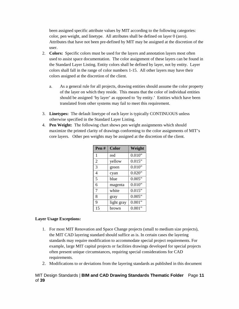
4. Pen Weight: The following chart shows pen weight assignments which should maximize the printed clarity of drawings conforming to the color assignments of MIT’s core layers. Other pen weights may be assigned at the discretion of the client.
Pen # Color Weight 1 red 0.010” 2 yellow 0.015” 3 green 0.010” 4 cyan 0.020” 5 blue 0.005” 6 magenta 0.010” 7 white 0.015” 8 gray 0.005” 9 light gray 0.001” 15 brown 0.001”
Layer Usage Exceptions:
1. For most MIT Renovation and Space Change projects (small to medium size projects), the MIT CAD layering standard should suffice as is. In certain cases the layering standards may require modification to accommodate special project requirements. For example, large MIT capital projects or facilities drawings developed for special projects often present unique circumstances, requiring special considerations for CAD requirements.
2. Modifications to or deviations from the layering standards as published in this document

MIT Design Standards | BIM and CAD Drawing Standards Thematic Folder Page 12 of 39
must be pre-approved by a member of MIT’s Facility Information Systems (FIS). Any special CAD requirements should be addressed at a joint meeting between the parties involved, prior to the development of CAD drawings for the project; otherwise the standards and guidelines in this document apply. Any changes need to be documented and submitted to FIS for approval.
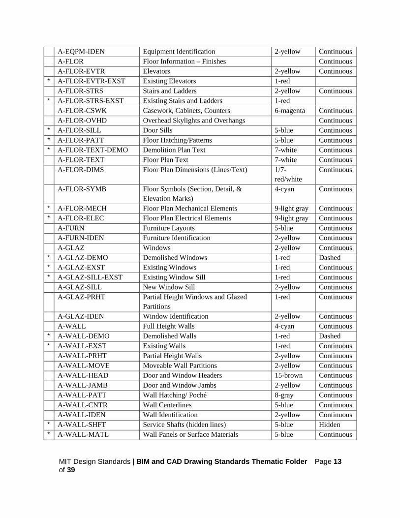
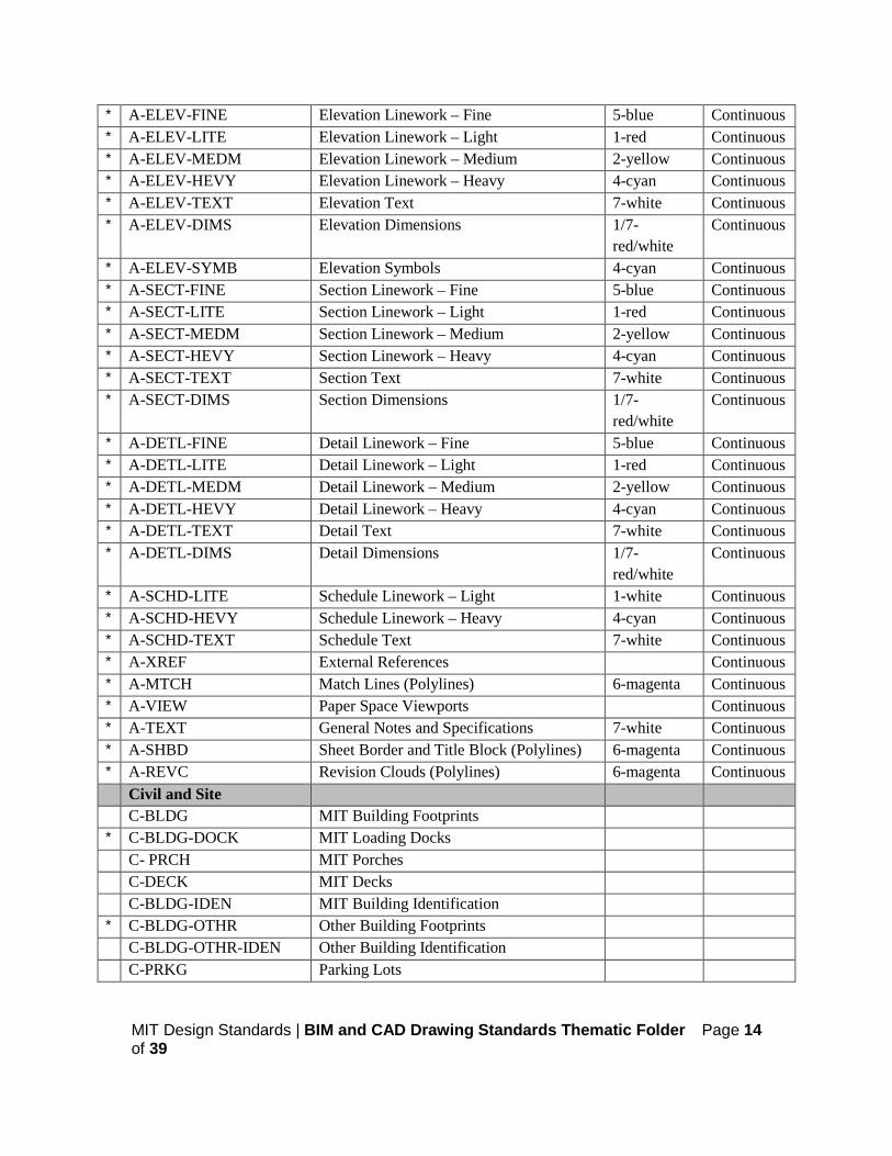
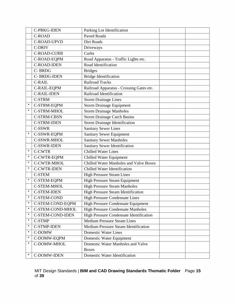
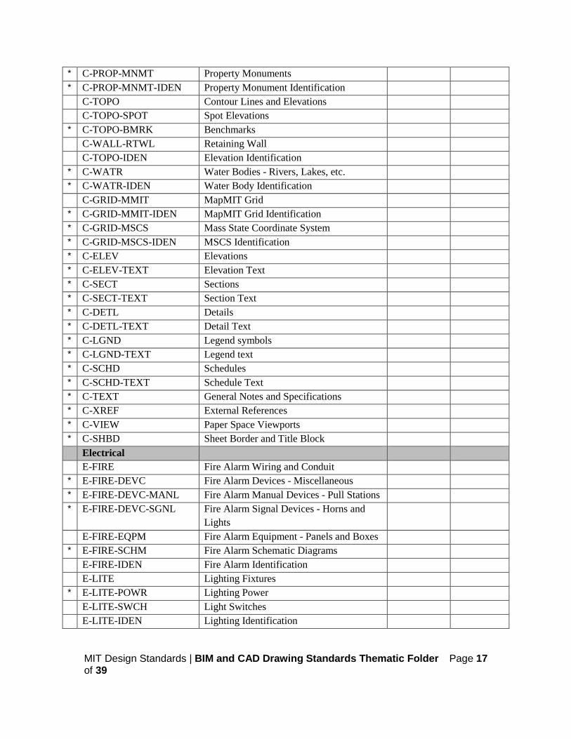
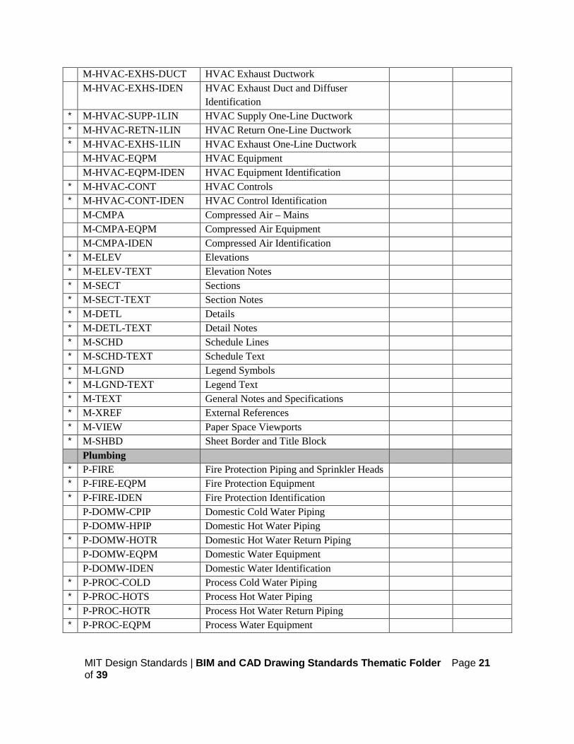
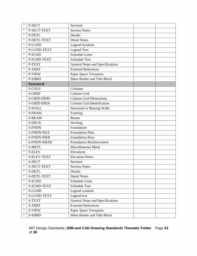
Standard Layer Listing:
The following layer list is an example of commonly used NCS layer names along with additional MIT specific layer names (marked with a * in the left hand column). Where MIT specific layer names differ from NCS, MIT layer names shall be used. For additional detail, beyond what is outlined herein, please refer to the National CAD Standard for guidance.
A copy of the National CAD Standard may be obtained from https://www.nationalcadstandard.org/ncs6/.
Name Description Color Linetype Architectural A-AREA Area Boundary Lines and Calculations 4-cyan Continuous A-AREA-IDEN Room Numbers and Identification, Area
Calculations 7-white Continuous
* A-AREA-PATT Area Hatching 8-gray Continuous A-CLNG Ceiling Information 1-red Continuous * A-CLNG-EXST Existing Ceiling 1-red Continuous A-CLNG-OPNG Overhead Skylights 6-magenta Hidden A-CLNG-GRID Ceiling Grid 3-green Continuous * A-CLNG-SOFF Ceiling Soffits 2-yellow Continuous * A-CLNG-OVHD Overhead Overhangs 6-magenta Hidden * A-CLNG-PATT Ceiling Hatching/Patterns 8-gray Continuous A-CLNG-TEXT Ceiling Plan Text 7-white Continuous A-CLNG-DIMS Ceiling Plan Dimensions 1/7-
red/white Continuous
A-CLNG-SYMB Ceiling Symbols (Section, Detail & Elevation Marks)
4-cyan Continuous
* A-CLNG-MECH Ceiling Plan Mechanical Elements 4-cyan Continuous * A-CLNG-ELEC Ceiling Plan Electrical Elements 4-cyan Continuous A-DOOR Doors 2-yellow Continuous * A-DOOR-DEMO Demolished Doors 1-red Dashed * A-DOOR-EXST Existing Doors 1-red Continuous A-DOOR-IDEN Door Identification 2-yellow Continuous A-EQPM Equipment 6-magenta Continuous
MIT Design Standards | BIM and CAD Drawing Standards Thematic Folder Page 13 of 39
A-EQPM-IDEN Equipment Identification 2-yellow Continuous A-FLOR Floor Information – Finishes Continuous A-FLOR-EVTR Elevators 2-yellow Continuous * A-FLOR-EVTR-EXST Existing Elevators 1-red A-FLOR-STRS Stairs and Ladders 2-yellow Continuous * A-FLOR-STRS-EXST Existing Stairs and Ladders 1-red A-FLOR-CSWK Casework, Cabinets, Counters 6-magenta Continuous A-FLOR-OVHD Overhead Skylights and Overhangs Continuous * A-FLOR-SILL Door Sills 5-blue Continuous * A-FLOR-PATT Floor Hatching/Patterns 5-blue Continuous * A-FLOR-TEXT-DEMO Demolition Plan Text 7-white Continuous A-FLOR-TEXT Floor Plan Text 7-white Continuous A-FLOR-DIMS Floor Plan Dimensions (Lines/Text) 1/7-
red/white Continuous
A-FLOR-SYMB Floor Symbols (Section, Detail, & Elevation Marks)
4-cyan Continuous
* A-FLOR-MECH Floor Plan Mechanical Elements 9-light gray Continuous * A-FLOR-ELEC Floor Plan Electrical Elements 9-light gray Continuous A-FURN Furniture Layouts 5-blue Continuous A-FURN-IDEN Furniture Identification 2-yellow Continuous A-GLAZ Windows 2-yellow Continuous * A-GLAZ-DEMO Demolished Windows 1-red Dashed * A-GLAZ-EXST Existing Windows 1-red Continuous * A-GLAZ-SILL-EXST Existing Window Sill 1-red Continuous A-GLAZ-SILL New Window Sill 2-yellow Continuous A-GLAZ-PRHT Partial Height Windows and Glazed
Partitions 1-red Continuous
A-GLAZ-IDEN Window Identification 2-yellow Continuous A-WALL Full Height Walls 4-cyan Continuous * A-WALL-DEMO Demolished Walls 1-red Dashed * A-WALL-EXST Existing Walls 1-red Continuous A-WALL-PRHT Partial Height Walls 2-yellow Continuous A-WALL-MOVE Moveable Wall Partitions 2-yellow Continuous A-WALL-HEAD Door and Window Headers 15-brown Continuous A-WALL-JAMB Door and Window Jambs 2-yellow Continuous A-WALL-PATT Wall Hatching/ Poché 8-gray Continuous A-WALL-CNTR Wall Centerlines 5-blue Continuous A-WALL-IDEN Wall Identification 2-yellow Continuous * A-WALL-SHFT Service Shafts (hidden lines) 5-blue Hidden * A-WALL-MATL Wall Panels or Surface Materials 5-blue Continuous
MIT Design Standards | BIM and CAD Drawing Standards Thematic Folder Page 14 of 39
* A-ELEV-FINE Elevation Linework – Fine 5-blue Continuous * A-ELEV-LITE Elevation Linework – Light 1-red Continuous * A-ELEV-MEDM Elevation Linework – Medium 2-yellow Continuous * A-ELEV-HEVY Elevation Linework – Heavy 4-cyan Continuous * A-ELEV-TEXT Elevation Text 7-white Continuous * A-ELEV-DIMS Elevation Dimensions 1/7-
red/white Continuous
* A-ELEV-SYMB Elevation Symbols 4-cyan Continuous * A-SECT-FINE Section Linework – Fine 5-blue Continuous * A-SECT-LITE Section Linework – Light 1-red Continuous * A-SECT-MEDM Section Linework – Medium 2-yellow Continuous * A-SECT-HEVY Section Linework – Heavy 4-cyan Continuous * A-SECT-TEXT Section Text 7-white Continuous * A-SECT-DIMS Section Dimensions 1/7-
red/white Continuous
* A-DETL-FINE Detail Linework – Fine 5-blue Continuous * A-DETL-LITE Detail Linework – Light 1-red Continuous * A-DETL-MEDM Detail Linework – Medium 2-yellow Continuous * A-DETL-HEVY Detail Linework – Heavy 4-cyan Continuous * A-DETL-TEXT Detail Text 7-white Continuous * A-DETL-DIMS Detail Dimensions 1/7-
red/white Continuous
* A-SCHD-LITE Schedule Linework – Light 1-white Continuous * A-SCHD-HEVY Schedule Linework – Heavy 4-cyan Continuous * A-SCHD-TEXT Schedule Text 7-white Continuous * A-XREF External References Continuous * A-MTCH Match Lines (Polylines) 6-magenta Continuous * A-VIEW Paper Space Viewports Continuous * A-TEXT General Notes and Specifications 7-white Continuous * A-SHBD Sheet Border and Title Block (Polylines) 6-magenta Continuous * A-REVC Revision Clouds (Polylines) 6-magenta Continuous Civil and Site C-BLDG MIT Building Footprints * C-BLDG-DOCK MIT Loading Docks C- PRCH MIT Porches C-DECK MIT Decks C-BLDG-IDEN MIT Building Identification * C-BLDG-OTHR Other Building Footprints C-BLDG-OTHR-IDEN Other Building Identification C-PRKG Parking Lots
MIT Design Standards | BIM and CAD Drawing Standards Thematic Folder Page 15 of 39
C-PRKG-IDEN Parking Lot Identification C-ROAD Paved Roads C-ROAD-UPVD Dirt Roads C-DRIV Driveways C-ROAD-CURB Curbs C-ROAD-EQPM Road Apparatus - Traffic Lights etc. C-ROAD-IDEN Road Identification C- BRDG Bridges C- BRDG-IDEN Bridge Identification C-RAIL Railroad Tracks C-RAIL-EQPM Railroad Apparatus - Crossing Gates etc. C-RAIL-IDEN Railroad Identification C-STRM Storm Drainage Lines * C-STRM-EQPM Storm Drainage Equipment * C-STRM-MHOL Storm Drainage Manholes C-STRM-CBSN Storm Drainage Catch Basins C-STRM-IDEN Storm Drainage Identification C-SSWR Sanitary Sewer Lines * C-SSWR-EQPM Sanitary Sewer Equipment C-SSWR-MHOL Sanitary Sewer Manholes C-SSWR-IDEN Sanitary Sewer Identification * C-CWTR Chilled Water Lines * C-CWTR-EQPM Chilled Water Equipment * C-CWTR-MHOL Chilled Water Manholes and Valve Boxes * C-CWTR-IDEN Chilled Water Identification C-STEM High Pressure Steam Lines * C-STEM-EQPM High Pressure Steam Equipment C-STEM-MHOL High Pressure Steam Manholes * C-STEM-IDEN High Pressure Steam Identification * C-STEM-COND High Pressure Condensate Lines * C-STEM-COND-EQPM High Pressure Condensate Equipment * C-STEM-COND-MHOL High Pressure Condensate Manholes * C-STEM-COND-IDEN High Pressure Condensate Identification * C-STMP Medium Pressure Steam Lines * C-STMP-IDEN Medium Pressure Steam Identification * C-DOMW Domestic Water Lines * C-DOMW-EQPM Domestic Water Equipment * C-DOMW-MHOL Domestic Water Manholes and Valve
Boxes
* C-DOMW-IDEN Domestic Water Identification

MIT Design Standards | BIM and CAD Drawing Standards Thematic Folder Page 16 of 39
* C-CDSR Condenser Water Lines * C-CDSR-EQPM Condenser Water Equipment * C-CDSR-IDEN Condenser Water Identification * C-FOIL Fuel Oil Lines * C-FOIL-EQPM Fuel Oil Equipment * C-FOIL-IDEN Fuel Oil Identification C-NGAS Natural Gas Lines C-NGAS-EQPM Natural Gas Equipment C-NGAS-MHOL Natural Gas Manholes and Valve Boxes C-NGAS-IDEN Natural Gas Identification C-FIRE Fire Protection Lines * C-FIRE-EQPM Fire Protection Equipment C-FIRE-MHOL Fire Protection Manholes and Valve Boxes C-FIRE-HYDT Fire Hydrants C-FIRE-IDEN Fire Identification * C-ELEC Electrical Distribution - Duct Banks * C-ELEC-MHOL Electrical Manholes and Hand Holes * C-ELEC-EQPM Electrical Equipment - Substations,
Generators, Transformers etc.
* C-ELEC-LITE Site Lighting * C-ELEC-POWR Misc Underground Power * C-ELEC-FIRE Fire Alarm Distribution * C-ELEC-FIRE-IDEN Fire Alarm Identification * C-ELEC-FIRE-MHOL Fire Alarm Manholes and Hand Holes * C-ELEC-FIRE-PSTN Fire Alarm Pull Stations * C-ELEC-POLE Utility Poles * C-ELEC-IDEN Electrical Identification C-COMM Telecomm Distribution - Duct Banks * C-COMM-MHOL Telecomm Manholes and Hand Holes * C-COMM-EMER Emergency Telephones C-COMM-IDEN Telecommunication Identification C-CATV Cable TV * C-CATV-IDEN Cable TV Identification C-PROP Property Lines C-PROP-IDEN Property Identification C- ESMT Property Easements C- ESMT-IDEN Easement Identification * C-PROP-PRCL Parcel Lines * C-PROP-PRCL-IDEN Parcel Identification
MIT Design Standards | BIM and CAD Drawing Standards Thematic Folder Page 17 of 39
* C-PROP-MNMT Property Monuments * C-PROP-MNMT-IDEN Property Monument Identification C-TOPO Contour Lines and Elevations C-TOPO-SPOT Spot Elevations * C-TOPO-BMRK Benchmarks C-WALL-RTWL Retaining Wall C-TOPO-IDEN Elevation Identification * C-WATR Water Bodies - Rivers, Lakes, etc. * C-WATR-IDEN Water Body Identification C-GRID-MMIT MapMIT Grid * C-GRID-MMIT-IDEN MapMIT Grid Identification * C-GRID-MSCS Mass State Coordinate System * C-GRID-MSCS-IDEN MSCS Identification * C-ELEV Elevations * C-ELEV-TEXT Elevation Text * C-SECT Sections * C-SECT-TEXT Section Text * C-DETL Details * C-DETL-TEXT Detail Text * C-LGND Legend symbols * C-LGND-TEXT Legend text * C-SCHD Schedules * C-SCHD-TEXT Schedule Text * C-TEXT General Notes and Specifications * C-XREF External References * C-VIEW Paper Space Viewports * C-SHBD Sheet Border and Title Block Electrical E-FIRE Fire Alarm Wiring and Conduit * E-FIRE-DEVC Fire Alarm Devices - Miscellaneous * E-FIRE-DEVC-MANL Fire Alarm Manual Devices - Pull Stations * E-FIRE-DEVC-SGNL Fire Alarm Signal Devices - Horns and
Lights
E-FIRE-EQPM Fire Alarm Equipment - Panels and Boxes * E-FIRE-SCHM Fire Alarm Schematic Diagrams E-FIRE-IDEN Fire Alarm Identification E-LITE Lighting Fixtures * E-LITE-POWR Lighting Power E-LITE-SWCH Light Switches E-LITE-IDEN Lighting Identification

MIT Design Standards | BIM and CAD Drawing Standards Thematic Folder Page 18 of 39
* E-EQPM-13_8 13.8KV Equipment * E-EQPM-208V 120/208V Equipment - Switches, XFMRs,
Panels
* E-EQPM-2400 2400V Equipment * E-EQPM-480V 277/480V Equipment * E-POWR-13_8 13.8 KV Power Circuits * E-POWR-13_8-IDEN 13.8KV Power Identification * E-POWR-1LIN One Line Power Diagrams * E-POWR-208V 120/208V Power Circuits * E-POWR-208V-IDEN 120/208V Power Identification * E-POWR-2400 2400V Power Circuits * E-POWR-2400-IDEN 2400V Power Identification * E-POWR-480V 277/480V Power Circuits * E-POWR-480V-IDEN 277/480V Power Identification E-COMM Communications Wiring and Conduit E-COMM-EQPM Communications Devices and Equipment E-COMM-IDEN Communications Identification * E-SECR Security Wiring, Conduit * E-SECR-EQPM Security Devices, Equipment * E-SECR-IDEN Security Identification E-LITE-EMER Emergency Lighting * E-EMER-POWR Emergency Power * E-EMER-EQPM Emergency Equipment * E-EMER-IDEN Emergency Identification E-CONT Electrical Controls E-CONT-IDEN Electrical Controls Identification E-GRND Ground System E-GRND-IDEN Ground System Identification * E-ELEV Elevations * E-ELEV-TEXT Elevation Notes * E-SECT Sections * E-SECT-TEXT Section Notes * E-DETL Details * E-DETL-TEXT Detail Notes * E-SCHD Schedule Lines * E-SCHD-TEXT Schedule Text * E-LGND Legend Symbols * E-LGND-TEXT Legend Text * E-TEXT General Notes and Specifications * E-XREF External References

MIT Design Standards | BIM and CAD Drawing Standards Thematic Folder Page 19 of 39
* E-VIEW Paper Space Viewports * E-SHBD Sheet Border and Title Block Landscape L-PLNT Plants and Landscaping L-PLNT-TREE Trees and Shrubs L-PLNT-GCVR Ground Covers and Vines L-PLNT-BEDS Rock, Bark and Landscaping Beds L-PLNT-TURF Lawn Areas L-PLNT-IDEN Plant and Landscaping Identification L-IRRG Irrigation Piping L-IRRG-SPKL Irrigation Sprinklers L-IRRG-IDEN Irrigation Identification L-SITE Site Improvements * L-SITE-CONC Concrete Pads L- FENC Fencing L-SITE-STEP Steps * L-SITE-SIGN Signs * L-SITE-RAMP Handicap Ramps and Access L-SITE-WALL Walls L-SITE-SWLK Walkways L-SITE-TRAL Dirt Paths L-SITE-FURN Site Furnishings L-SITE-SPRT Athletic Fields L-SITE-IDEN Site Identification * L-ELEV Elevations * L-SECT Sections * L-DETL Details * L-SCHD Schedules * L-SCHD-TEXT Schedule Text * L-LGND Legend Symbols * L-LGND-TEXT Legend text * L-TEXT General Notes and Specifications * L-XREF External References * L-VIEW Paper Space Viewports * L-SHBD Sheet Border and Title Block Mechanical M-CWTR Chilled Water Supply/Return Piping M-CWTR-EQPM Chilled Water Equipment * M-CWTR-PROC Secondary Chilled Water - Equipment
Cooling

MIT Design Standards | BIM and CAD Drawing Standards Thematic Folder Page 20 of 39
M-CWTR-IDEN Chilled Water Identification M-CNDW Condenser Water Supply/Return Piping M-CNDW-EQPM Condenser Water Equipment M-CNDW-IDEN Condenser Water Identification * M-HWTR Heating Hot Water Supply/Return Piping M-HWTR-EQPM Heating Hot Water Equipment M-HWTR-IDEN Heating Hot Water Identification M-REFG Refrigeration Piping M-REFG-EQPM Refrigeration Equipment M-REFG-IDEN Refrigeration Identification M-STEM-HPIP High Pressure Steam Piping M-STEM-HPIP-EQPM High Pressure Steam Equipment M-STEM-HPIP-IDEN High Pressure Identification M-STEM-HPIP-COND High Pressure Condensate Piping M-STEM-HPIP-COND-
IDEN High Pressure Condensate Identification
M-STEM-MPIP Medium Pressure Steam Piping M-STEM-MPIP-IDEN Medium Pressure Steam Identification M-STEM-LPIP Low Pressure Steam Piping M-STEM-LPIP-IDEN Low Pressure Steam Identification M-STEM-LPIP-COND Low Pressure Condensate Piping M-STEM-LPIP-COND-
IDEN Low Pressure Condensate Identification
M-STEM-LPIP-PROC Low Pressure Process Steam Piping M-STEM-LPIP-PROC-
IDEN Low Pressure Process Identification
M-RCOV-PIPE Heat Recovery Piping M-RCOV-EQPM Heat Recovery Equipment M-RCOV-IDEN Heat Recovery Identification M-FUEL-OGEP Fuel Oil Piping M-FUEL-OGEP-IDEN Fuel Oil Identification M-HVAC-SPLY-SDFF HVAC Supply Diffusers M-HVAC-SPLY-DUCT HVAC Supply Ductwork M-HVAC-SPLY-IDEN HVAC Supply Ductwork and Diffuser
Identification
M-HVAC-RETN-RDFF HVAC Return Diffusers M-HVAC-RETN-DUCT HVAC Return Ductwork M-HVAC-RETN-IDEN HVAC Return Duct and Diffuser
Identification
* M-HVAC-EXHS-EDFF HVAC Exhaust Diffusers
MIT Design Standards | BIM and CAD Drawing Standards Thematic Folder Page 21 of 39
M-HVAC-EXHS-DUCT HVAC Exhaust Ductwork M-HVAC-EXHS-IDEN HVAC Exhaust Duct and Diffuser
Identification
* M-HVAC-SUPP-1LIN HVAC Supply One-Line Ductwork * M-HVAC-RETN-1LIN HVAC Return One-Line Ductwork * M-HVAC-EXHS-1LIN HVAC Exhaust One-Line Ductwork M-HVAC-EQPM HVAC Equipment M-HVAC-EQPM-IDEN HVAC Equipment Identification * M-HVAC-CONT HVAC Controls * M-HVAC-CONT-IDEN HVAC Control Identification M-CMPA Compressed Air – Mains M-CMPA-EQPM Compressed Air Equipment M-CMPA-IDEN Compressed Air Identification * M-ELEV Elevations * M-ELEV-TEXT Elevation Notes * M-SECT Sections * M-SECT-TEXT Section Notes * M-DETL Details * M-DETL-TEXT Detail Notes * M-SCHD Schedule Lines * M-SCHD-TEXT Schedule Text * M-LGND Legend Symbols * M-LGND-TEXT Legend Text * M-TEXT General Notes and Specifications * M-XREF External References * M-VIEW Paper Space Viewports * M-SHBD Sheet Border and Title Block Plumbing * P-FIRE Fire Protection Piping and Sprinkler Heads * P-FIRE-EQPM Fire Protection Equipment * P-FIRE-IDEN Fire Protection Identification P-DOMW-CPIP Domestic Cold Water Piping P-DOMW-HPIP Domestic Hot Water Piping * P-DOMW-HOTR Domestic Hot Water Return Piping P-DOMW-EQPM Domestic Water Equipment P-DOMW-IDEN Domestic Water Identification * P-PROC-COLD Process Cold Water Piping * P-PROC-HOTS Process Hot Water Piping * P-PROC-HOTR Process Hot Water Return Piping * P-PROC-EQPM Process Water Equipment

MIT Design Standards | BIM and CAD Drawing Standards Thematic Folder Page 22 of 39
* P-PROC-IDEN Process Water Identification * P-RCVR Recovered Water Piping * P-RCVR-EQPM Recovered Water Equipment * P-RCVR-IDEN Recovered Water Identification * P-CMPA Lab Air Piping * P-CMPA-EQPM Lab Air Equipment * P-CMPA-IDEN Lab Air Identification * P-VACM Vacuum Piping * P-VACM-EQPM Vacuum Equipment * P-VACM-IDEN Vacuum Identification * P-CO2S CO2 Piping * P-CO2S-EQPM C02 Equipment * P-CO2S-IDEN C02 Identification * P-NIOX NO Piping * P-NIOX-EQPM NO Equipment * P-NIOX-IDEN NO Identification * P-NO2S NO2 Piping * P-NO2S-EQPM NO2 Equipment * P-NO2S-IDEN NO2 Identification * P-OXYG Oxygen Piping * P-OXYG-EQPM Oxygen Equipment * P-OXYG-IDEN Oxygen Identification * P-NGAS Natural Gas Piping * P-NGAS-EQPM Natural Gas Equipment * P-NGAS-IDEN Natural Gas Identification * P-PURE Pure Water Piping * P-PURE-EQPM Pure Water Equipment * P-PURE-IDEN Pure Water Identification P-SSWR-PIPE Sanitary Waste Piping P-SSWR-VENT Sanitary Vent Piping * P-SSWR-INDR Indirect Waste Piping * P-SSWR-LABS Lab Waste Piping * P-SSWR-LABS-VENT Lab Vent Piping P-SSWR-IDEN Sanitary Identification P-STRM-PIPE Storm Drain Piping P-STRM-IDEN Storm Drain Identification * P-FIXT Plumbing Fixtures * P-FIXT-IDEN Plumbing Fixture Identification * P-ELEV Elevations * P-ELEV-TEXT Elevation Notes
MIT Design Standards | BIM and CAD Drawing Standards Thematic Folder Page 23 of 39
* P-SECT Sections * P-SECT-TEXT Section Notes * P-DETL Details * P-DETL-TEXT Detail Notes * P-LGND Legend Symbols * P-LGND-TEXT Legend Text * P-SCHD Schedule Lines * P-SCHD-TEXT Schedule Text * P-TEXT General Notes and Specifications * P-XREF External References * P-VIEW Paper Space Viewports * P-SHBD Sheet Border and Title Block Structural S-COLS Columns S-GRID Column Grid S-GRID-DIMS Column Grid Dimensions S-GRID-IDEN Column Grid Identification S-WALL Structural or Bearing Walls * S-FRAM Framing S-BEAM Beams S-DECK Decking S-FNDN Foundation S-FNDN-PILE Foundation Piles S-FNDN-PIER Foundation Piers S-FNDN-RBAR Foundation Reinforcement * S-METL Miscellaneous Metal * S-ELEV Elevations * S-ELEV-TEXT Elevation Notes * S-SECT Sections * S-SECT-TEXT Section Notes * S-DETL Details * S-DETL-TEXT Detail Notes * S-SCHD Schedule Lines * S-SCHD-TEXT Schedule Text * S-LGND Legend symbols * S-LGND-TEXT Legend text * S-TEXT General Notes and Specifications * S-XREF External References * S-VIEW Paper Space Viewports * S-SHBD Sheet Border and Title Block

MIT Design Standards | BIM and CAD Drawing Standards Thematic Folder Page 24 of 39
2.4 Translating CAD Files to DWG Format
Translating from other CAD Software:
MIT recognizes that many of its vendors do not use the same version of design software to produce plans for their projects. However, MIT requires that service providers who work with other file formats submit DWG formatted CAD files upon project closeout that are fully compliant with all of the standards outlined herein, and which have no significant loss of drawing entities or project data that can result from standard CAD file translation procedures.
Translating from BIM Software:
Projects using Building Information Modeling (BIM) software are still required to produce DWG and PDF/TIF formats for their projects. The use of the National CAD Standard will help facilitate the production of properly formed DWG files.
DWG File Translation Testing:
For firms translating their native CAD file format into DWG format concerned about delivering error-free CAD files to MIT upon project closeout, it is strongly recommended that thorough file translation testing be conducted before the drawing development phase of the project. This will assure early detection of file conversion issues, if any, and allow for corrective measures to be taken before the project closeout period. DXF files will not be accepted at project closeout as a substitution for DWG file deliverables.
Error Free DWG Files:
All DWG files and CAD drawing entities submitted at the end of a project must be able to be manipulated using standard AutoCAD® drafting procedures. Files with proprietary features from other AutoCAD add-ons will not be accepted. Non-compliance with this policy will result in the rejection of DWG files submitted at project closeout in addition to delayed rendering of final project payment.
MIT Design Standards | BIM and CAD Drawing Standards Thematic Folder Page 25 of 39
3. USE OF BUILDING INFORMATION MODELING (BIM)
3.1 MIT Requirements
Many projects are utilizing Building Information Modeling (BIM) for design and construction projects at MIT. While this practice is encouraged, the 2D deliverables are still required as outlined in this guideline and as specified in MIT contracts.
3.2 BIM Execution Plan
Refer to Appendix A - BIM Execution Plan. Document is to be completed by project teams as indicated. Projects using BIM are required to use the MIT BIM Execution Plan to document modeling practices. This document declares what is being modeled, the accuracy of the models, the intent of the models, and how project teams work within the models. Software platforms and procedures are also outlined and agreed upon in this document.
The MIT BIM Execution Plan template is available upon request to [email protected].
3.3 BIM Standards
There are a number of evolving standards for the use of BIM. Since no one standard can be applied to all types of MIT projects, it is recommended that modeling practices and standards be declared and agreed upon in the project’s BIM Execution Plan (BEP).
Use of Industry Foundation Classes (IFC): Currently MIT is working on its internal BIM standards, but until the standard is complete the use of IFC and the creation of IFC compliant models is highly recommended. Information about IFC can be found at the BuildingSMART Alliance website at: http://www.nibs.org/
Other BIM Standards:
If other BIM standard is being used for a project, for example OmniClass, it must be declared and agreed upon in the project’s BIM Execution Plan before the start of the project.

MIT Design Standards | BIM and CAD Drawing Standards Thematic Folder Page 26 of 39
3.4 BIM Models and Deliverables
Models turned over to MIT as a deliverable must meet the requirements of the agreed upon MIT BIM Execution Plan. Internally, MIT has standardized its BIM environment on Autodesk’s BIM platform and models created for projects are expected to work within MIT’s CAD/BIM environment.
Use of Revit and NavisWorks:
1. It is recommended that models are created in the most current versions of Autodesk Revit or Autodesk NavisWorks. Modeling practices are declared in the project’s BIM Execution Plan and best practices for model creation include, but are not limited to:
a. Consisted file naming convention. b. Models must not have linked models. c. Vertical and Horizontal Coordinates must comply with MIT’s Survey Guidelines.
2. Naming conventions of models delivered to MIT should closely follow the naming conventions outlined in File Organization and Transmittal to MIT below.
Use of Other BIM Products:
1. It is understood that different disciplines require the use of different types of software. These software packages need to be declared in the BIM Execution Plan and their use must result in the creation of proper 2D products and with models that can be used.
BIM Deliverables:
1. Its MIT’s philosophy that the use of BIM will assist in the creation accurate deliverables as outlined in this document. When models are considered as part of the deliverable and conform to the projects BIM Execution Plan, the MIT BIM Execution Plan itself is considered a required deliverable. Models created with the use of BIM also need to be outlined in the Electronic File Index listed in Appendix A.
4. ARCHIVAL PRINT FILES
The intent of requiring Archival Print Files is to receive a file of sufficient detail to recreate 100% of the information contained in the hard copy original, without creating an excessively large digital file. Every sheet in the record or construction drawings needs to have a corresponding (1:1) Archival Print File. These files must be either PDF or TIF formats and they may be produced either directly from CAD/BIM applications or from a scanned hard copy (PLT files and other print file formats will not be accepted).
MIT Design Standards | BIM and CAD Drawing Standards Thematic Folder Page 27 of 39
Regardless of production method, the Archive Print Files must match the content of the materials being submitted at closeout. The names of these files must also be the same as the DWG files they represent, therefore multipage TIF/PDF files will not be accepted. All Archival Print Files must follow these production requirements and must be listed with their DWG counterparts in the Electronic File Index listed in Appendix A.
4.1 PDF File Creation
Creation from DWG:
1. PDF files from DWG files must mirror the color and line thickness that were represented by the print products. To create these files, the same print settings should be used to generate the PDF files. Unless colors are used in the files, PDF files with AutoCAD layer colors instead of their line settings will not be accepted since this is not a true representation of the project documentation.
Linework and Resolution:
1. When possible, PDF files should be in vector format to provide crisp line work for drawings. Files needing to be rasterized or scanned may be produced in PDF format and should be created at a resolution of 300dpi or higher. A 24 by 36 inch original at 300dpi will result in an image 7,200 pixels by 10,800 pixels, but higher resolution can be used if 300dpi does not accurately reproduce all content in ad drawings. Do not adjust paper settings to achieve 300dpi.
BIT Depth:
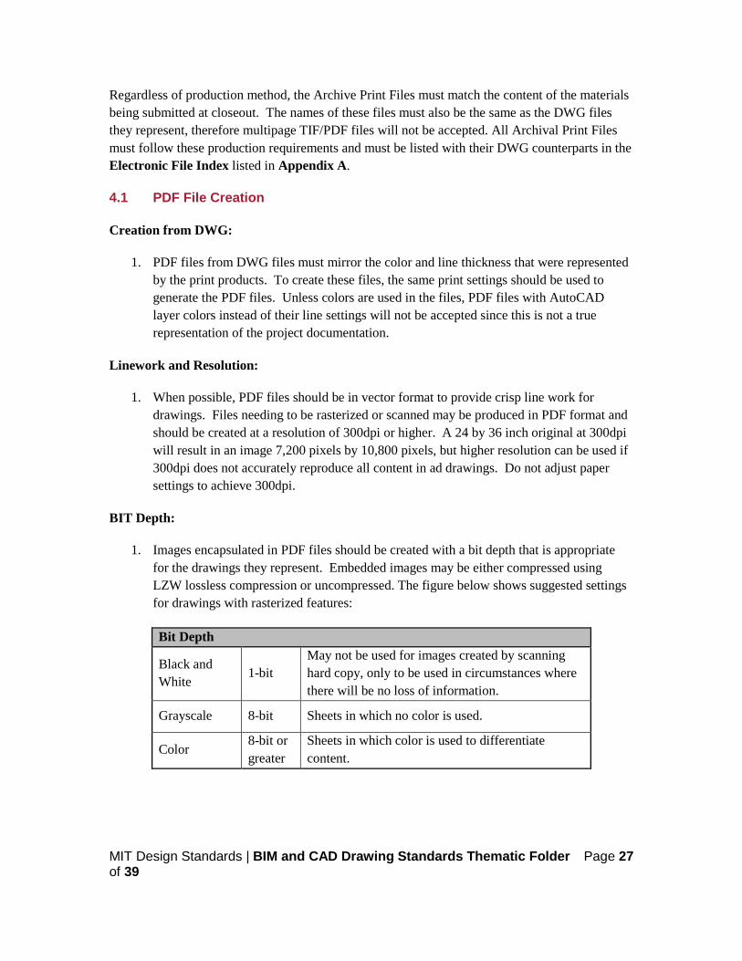
1. Images encapsulated in PDF files should be created with a bit depth that is appropriate for the drawings they represent. Embedded images may be either compressed using LZW lossless compression or uncompressed. The figure below shows suggested settings for drawings with rasterized features:
Bit Depth
Black and White
1-bit May not be used for images created by scanning hard copy, only to be used in circumstances where there will be no loss of information.
Grayscale 8-bit Sheets in which no color is used.
Color 8-bit or greater
Sheets in which color is used to differentiate content.
MIT Design Standards | BIM and CAD Drawing Standards Thematic Folder Page 28 of 39
4.2 TIF File Creation
Creation from Scanning:
1. Generating TIF files by scanning the hard copy drawing are accepted. Please refer to the Bit Depth table above for appropriate resolutions and bit depths. JPG files will not be accepted in place of TIF or PDF files.
Creation from AutoCAD®:
1. Creation of TIF files directly from AutoCAD® is not recommended. PDF files are the preferred file format when producing Archival Print Files from CAD/BIM software.
Creation from Other Formats:
1. Converting to TIF from other image file formats, the format being converted from must be a lossless format like PNG or GIF. Firms should not convert from a file format that uses lossy compression, such as JPEG, due to degradation of the image. Images should not be resampled in order to increase resolution to 300dpi.
5. FILE IDENTIFICATION AND NAMING CONVENTIONS
MIT requires that for each sheet submitted as a project deliverable there is a corresponding DWG and Archive Print File (PDF or TIF). The sheet and the digital files should follow the same naming convention. Each print file’s name should have the same name as its source DWG file.
5.1 DWG Sheet Identification
Larger Capital Projects should use the following sheet identification format. It is a consistent format that contains five alphanumeric characters in a specific sequence conveying meaningful information to both the drawing creator and user. The sheet identifier consists of three components: the discipline designator, the sheet type designator, and the sheet sequence.

MIT Design Standards | BIM and CAD Drawing Standards Thematic Folder Page 29 of 39
Discipline Designators:
1. The discipline designator consists of one alphabetical character and a hyphen or two alphabetical characters. The codes used for the discipline designator are listed in the Layer Naming Convention. The discipline designator identifies the sheet as a member of a particular genre of drawings and is one character. For more specific genres, such as security (SC) or audio visual (AV) drawings, creators can use a two-character designator. Not all type designators are required. The standard also does not prohibit combining different types of drawings onto the same sheet. Basic discipline designators are listed below:
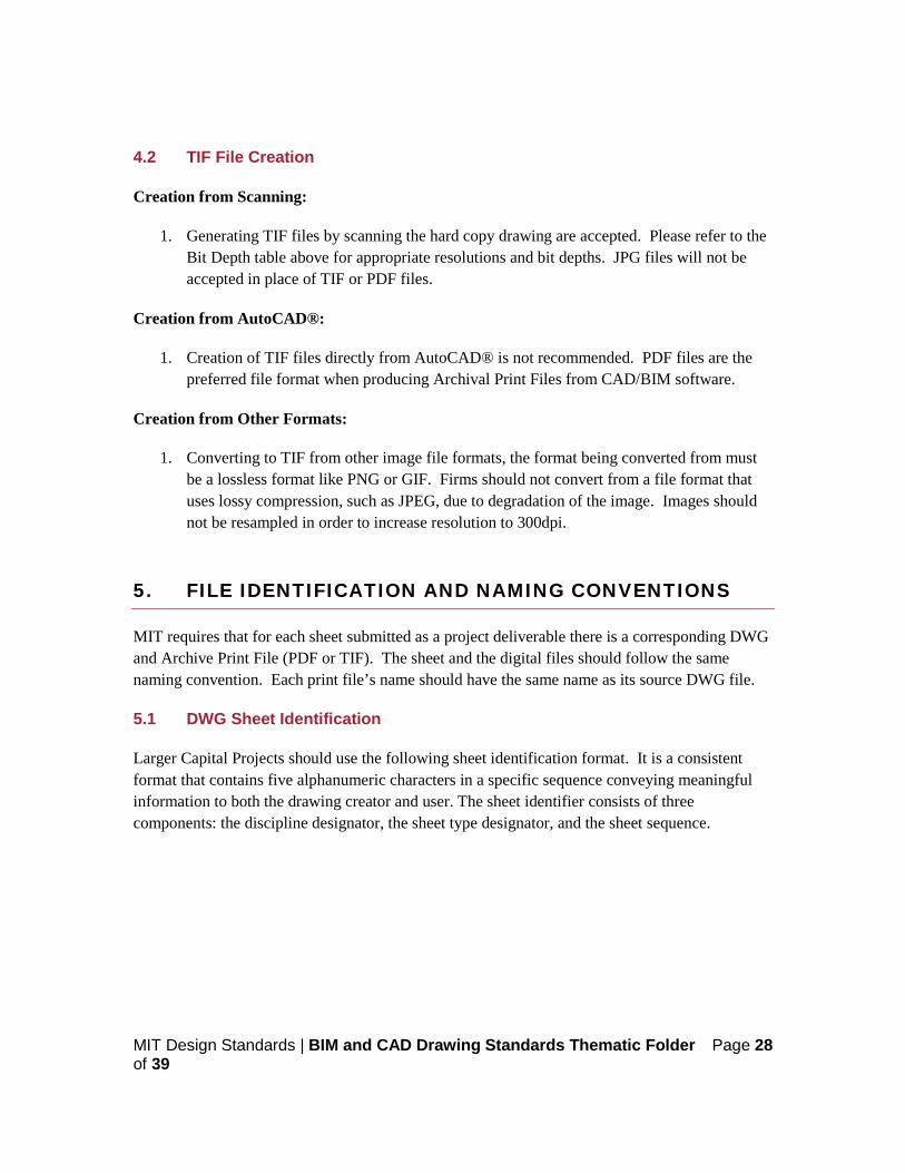
Sheet Type Designators:
1. Sheet type designators consist of one numeric character. The sheet type designator refers to the type of information displayed in the drawing.
MIT Design Standards | BIM and CAD Drawing Standards Thematic Folder Page 30 of 39
Sheet Sequence Numbers:
1. Sheet sequence numbers consists of two numeric characters in sequential order from 00 through 99. Example: Second floor plan - A102.
5.2 File Organization and Transmittal to MIT
In order to keep track of materials submitted to MIT, a clear catalog of information needs to accompany the materials submitted to MIT. This includes materials on a disk, files conformation to a naming convention, CD/DVDs produces in a orderly way, and an index sheet naming each file and its description.
File Names:
1. MIT has its own file naming convention for archival purposes to make file easily identifiable to users. Though this naming convention is not required, it is good to be aware of the nomenclature used for archiving. Naming convention for MIT’s archiving system is as follows:
a. File: MIT_MG02_02145_A_AB_A-102.DWG b. Convention: [campus]_[building #]_[MIT project #]_[discipline]_
[phase]_[sheet #].[extension] c. Description: From the MIT campus, Main Group building 2, project number
02145 and is an architectural as-built, sheet A-102.
2. Please refer to the MIT Archiving Guidelines for other best practices when organizing project information.
File Transmittal:

MIT Design Standards | BIM and CAD Drawing Standards Thematic Folder Page 31 of 39
1. The content of electronic drawings must match the delivered original hard copy set exactly. To ensure the integrity of the electronic drawing set upon delivery to MIT:
a. Ensure the drawings adhere to the guidelines presented in this document. Review the procedures for preparing drawings for submittal as detailed in the preceding paragraphs.
b. Include a digital copy transmittal PDF with all submittals indicating MIT Project number, MIT Project name (if applicable) and complete listing of all filenames and sheet numbers. Please use the “Electronic Filing Index’ template when submitting documentation.
c. Submit Adobe PDF’s or TIF’s of the sheets, with file names corresponding to names of DWG files.
d. Submit all digital files on thumb drive, portable hard drives, CD-ROM or DVD-ROM to the MIT project manager. If external ftp or file transfer site is being used, please notify FIS.

MIT Design Standards | BIM and CAD Drawing Standards Thematic Folder Page 32 of 39
APPENDIX A: BIM EXECUTION PLAN
Please use the MIT BIM Execution Plan for all project utilizing building information modeling. This template can be requested at [email protected].
MIT Design Standards | BIM and CAD Drawing Standards Thematic Folder Page 33 of 39
APPENDIX B: GLOSSARY OF TERMS
The definitions below have been gathered from a variety of sources including online documents, the American Institute of Architects and MIT Staff. As-Built Drawings: As-built drawings are prepared by the contractor. They show, in red ink, on-site changes to the original construction documents. This set of drawings depicts the actual conditions of the completed construction “as it was built”. Basis of Design: The basis of design is the documentation of the primary thought processes and assumptions behind design decisions that were made to meet the Owner’s Project Requirements. The basis of design describes the systems, components, conditions and methods chosen to meet the intent. Some reiterating of the Owner’s Project Requirements may be included. Bid Documents: Documents required to be submitted in response to an Invitation To Bid (ITB). These include the prescribed bid form, drawings, specifications, time lines, charts, price breakdowns, etc. Commissioning Plan: An overall plan, developed before or after bidding, that provides the structure, schedule and coordination planning for the commissioning process. Construction Drawings: Drawings that provide all the necessary information, both graphic and written, to build the project. These drawings provide specific, detailed information regarding walls, doors, furniture, equipment, lighting, outlets, and so on. Design Drawings: Technical drawings used to fully and clearly define requirements for engineered items so that they may conform to the design aesthetic. The purpose of such a drawing is to accurately and unambiguously capture all the geometric features of a product or a component that will allow a manufacturer to produce that component. Final Commissioning Report:
MIT Design Standards | BIM and CAD Drawing Standards Thematic Folder Page 34 of 39
A final summary report by the Commissioning Authority provided to the Owner, focusing on evaluating commissioning process issues and identifying areas where the process could be improved. All acquired documentation, logs, minutes, reports, deficiency lists, communications, findings, unresolved issues, etc., are compiled in appendices and provided with the report Functional Performance Tests (FPT): A test of the dynamic function and operation of equipment and systems using manual (direct observation) or monitoring methods. Functional performance testing is the dynamic testing of systems (rather than just components) under full operation. Systems are tested under various modes, such as high and low cooling/heating loads, component failures, fire alarm, power failure, etc. The systems are run through all control system’s sequences of operation and components are verified to be responding as the sequences state. O&M Manuals: Operational and Maintenance Manuals include equipment specifications and schedules, drawings and overall information needed to maintain installed equipment. Owner’s Project Requirements: A dynamic document that provides the explanation of the ideas, concepts and criteria that are considered to be very important to the owner. It is initially the outcome of the programming and conceptual design phases. Pre-Functional Checklist (PFC): A list of items to inspect and elementary component tests to conduct to verify proper installation of equipment, provided by the Commissioning Authority to the Sub-Contractors. PFCs are primarily static inspections and procedures to prepare the equipment or system for initial operation (e.g., belt tension, oil levels OK, gages in place, etc.). However, some PFC items entail simple testing of the function of a component, a piece of equipment or system (such as measuring the voltage imbalance on a three phase pump motor of a chiller system). Record Drawings: Record drawings are prepared by the architect and reflect on-site changes the contractor noted in the as-built drawings. They are often compiled as a set of on-site changes made for the owner per the owner-architect contract. Shop Drawings: A drawing or set of drawings produced by the contractor, supplier, manufacturer, subcontractor, or fabricator typically required for pre-fabricated components. Sketches: A simple, technical drawing created to isolate a particular engineering/architectural item and provide specific requirements related to that item.

MIT Design Standards | BIM and CAD Drawing Standards Thematic Folder Page 35 of 39
Specifications: Specific qualitative statements of particular needs to be satisfied, or essential characteristics that a customer requires (in a good, material, method, process, service, system, or work) and which a vendor must deliver. They are usually written in a manner that enables all parties to measure the degree of conformance. Submittals: Product data submittals, samples, and shop drawings are required primarily for the architect and engineer to verify that the correct products will be installed on the project. This process also gives the architect and sub-consultants the opportunity to select colors, patterns, and types of material that were not chosen prior to completion of the construction drawings. Survey Drawings: A CAD plan prepared by a licensed surveyor, which shows all essential measurements taken in the survey. Each survey drawing will be tied into the MIT control network and be submitted in NAD 83 feet. Systems Manual: The Systems Manual expands the scope of the traditional operating and maintenance documentation to include the additional information gathered during the Commissioning Process and to provide a systems-based organization of information. The Systems Manual is intended to be useful in the day-to-day operations of a facility. Working Drawings: A complete set of plans and specifications showing and describing all phases of a project, architectural, structural, mechanical, electrical, civil engineering, and landscaping systems to the degree necessary for the purposes of accurate bidding by contractors and for the use of artisans in constructing the project.

MIT Design Standards | BIM and CAD Drawing Standards Thematic Folder Page 36 of 39
APPENDIX C: ELECTRONIC FILE INDEX
All electronic materials (CAD files, PDF and TIF files, index table files, etc.) must be delivered on a CD or DVD, formatted using Windows XP or higher. Indices for files must be submitted in both paper format and electronically in Microsoft Excel 2003 or higher. Indices must follow a format similar to the sample shown below. This template can be requested at [email protected].