Si 6303 / Si 6304 / Si 6305 - IMI Critical...3 Si 6303 / Si 6304 / Si 6305 Type code Order example 1...
18
Engineering GREAT Solutions
Transcript of Si 6303 / Si 6304 / Si 6305 - IMI Critical...3 Si 6303 / Si 6304 / Si 6305 Type code Order example 1...
Engineering GREAT SolutionsEngineering GREATGREAT
Process and steam safety valves to PED and DIN/EN standards
Si 6303 / Si 6304 / Si 6305
2
Si 6303 / Si 6304 / Si 6305
Si 6303 / Si 6304 / Si 6305
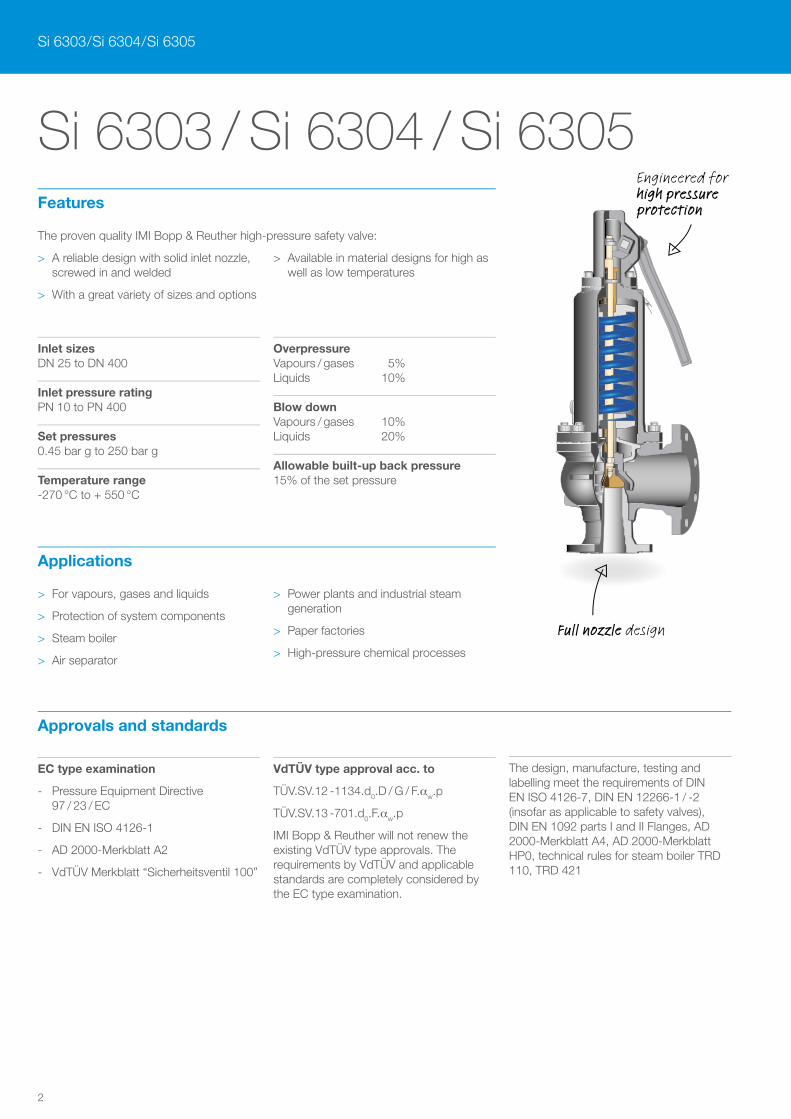
The proven quality IMI Bopp & Reuther high-pressure safety valve:
> A reliable design with solid inlet nozzle, screwed in and welded
> With a great variety of sizes and options
> Available in material designs for high as well as low temperatures
Features
Inlet sizesDN 25 to DN 400
Inlet pressure ratingPN 10 to PN 400
Set pressures0.45 bar g to 250 bar g
Temperature range-270 °C to + 550 °C
OverpressureVapours / gases 5%Liquids 10%
Blow downVapours / gases 10%Liquids 20%
Allowable built-up back pressure15% of the set pressure
> For vapours, gases and liquids
> Protection of system components
> Steam boiler
> Air separator
> Power plants and industrial steam generation
> Paper factories
> High-pressure chemical processes
Applications
Approvals and standards
EC type examination
- Pressure Equipment Directive 97 / 23 / EC
- DIN EN ISO 4126-1
- AD 2000-Merkblatt A2
- VdTÜV Merkblatt “Sicherheitsventil 100”
VdTÜV type approval acc. to
TÜV.SV.12 -1134.d0.D / G / F.aw.p
TÜV.SV.13 -701.d0.F.aw.p
IMI Bopp & Reuther will not renew the existing VdTÜV type approvals. The requirements by VdTÜV and applicable standards are completely considered by the EC type examination.
The design, manufacture, testing and labelling meet the requirements of DIN EN ISO 4126-7, DIN EN 12266-1 / -2 (insofar as applicable to safety valves), DIN EN 1092 parts I and II Flanges, AD 2000-Merkblatt A4, AD 2000-Merkblatt HP0, technical rules for steam boiler TRD 110, TRD 421
Full nozzle design
Engineered for high pressure protection
3
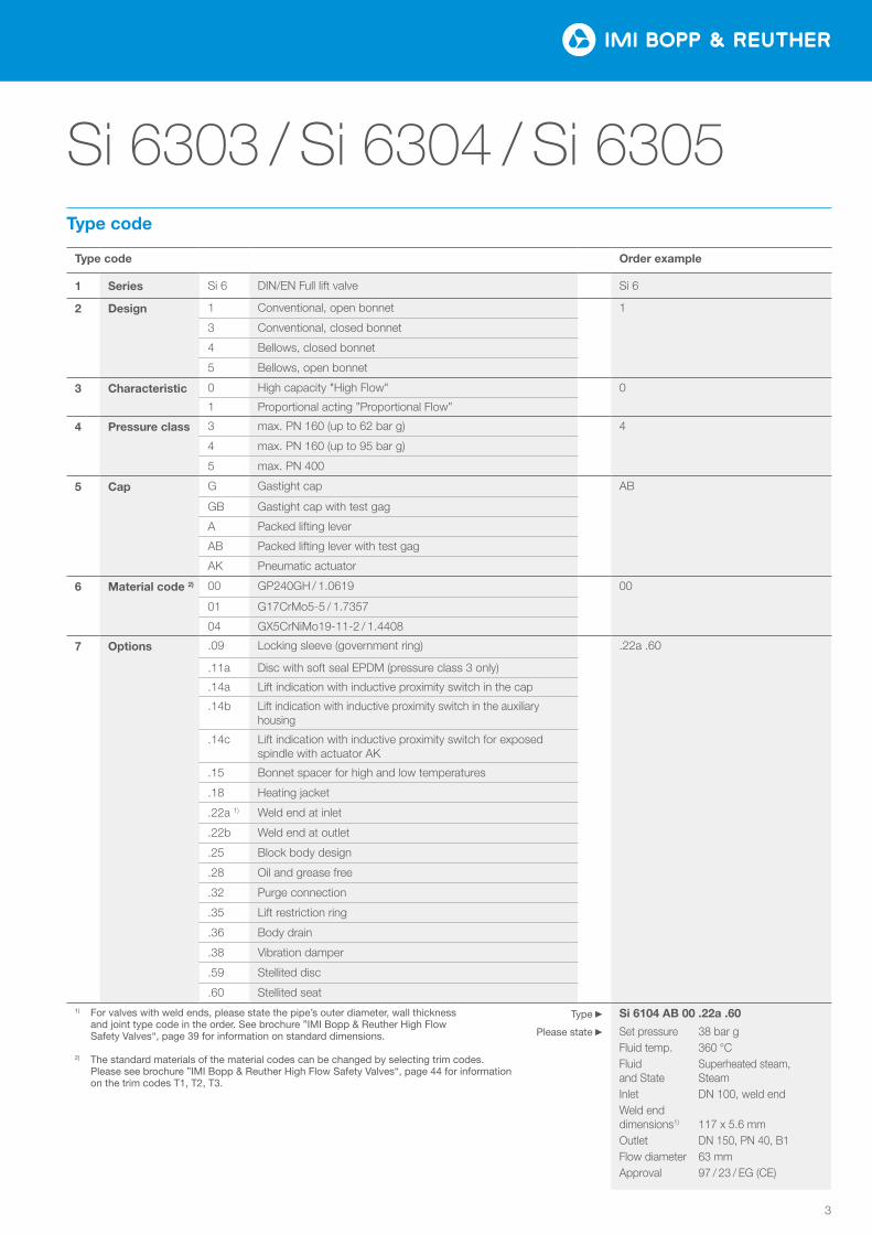
Si 6303 / Si 6304 / Si 6305
Type code Order example
1 Series Si 6 DIN/EN Full lift valve Si 6
2 Design 1 Conventional, open bonnet 1
3 Conventional, closed bonnet
4 Bellows, closed bonnet
5 Bellows, open bonnet
3 Characteristic 0 High capacity "High Flow" 0
1 Proportional acting ”Proportional Flow”
4 Pressure class 3 max. PN 160 (up to 62 bar g) 4
4 max. PN 160 (up to 95 bar g)
5 max. PN 400
5 Cap G Gastight cap AB
GB Gastight cap with test gag
A Packed lifting lever
AB Packed lifting lever with test gag
AK Pneumatic actuator
6 Material code 2) 00 GP240GH / 1.0619 00
01 G17CrMo5-5 / 1.7357
04 GX5CrNiMo19-11-2 / 1.4408
7 Options .09 Locking sleeve (government ring) .22a .60
.11a Disc with soft seal EPDM (pressure class 3 only)
.14a Lift indication with inductive proximity switch in the cap
.14b Lift indication with inductive proximity switch in the auxiliary housing
.14c Lift indication with inductive proximity switch for exposed spindle with actuator AK
.15 Bonnet spacer for high and low temperatures
.18 Heating jacket
.22a 1) Weld end at inlet
.22b Weld end at outlet
.25 Block body design
.28 Oil and grease free
.32 Purge connection
.35 Lift restriction ring
.36 Body drain
.38 Vibration damper
.59 Stellited disc
.60 Stellited seat1) For valves with weld ends, please state the pipe’s outer diameter, wall thickness
and joint type code in the order. See brochure ”IMI Bopp & Reuther High Flow Safety Valves“, page 39 for information on standard dimensions.
2) The standard materials of the material codes can be changed by selecting trim codes. Please see brochure ”IMI Bopp & Reuther High Flow Safety Valves“, page 44 for information on the trim codes T1, T2, T3.
Si 6104 AB 00 .22a .60
Set pressure 38 bar gFluid temp. 360 °CFluid Superheated steam, and State SteamInlet DN 100, weld endWeld end dimensions1) 117 x 5.6 mm Outlet DN 150, PN 40, B1Flow diameter 63 mmApproval 97 / 23 / EG (CE)
Type
Please state
Type code
4
Si 6303 / Si 6304 / Si 6305
Si 6303 / Si 6304 / Si 6305
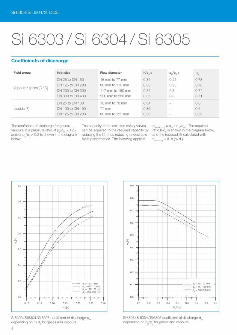
Fluid group Inlet size Flow diameter h/d0 ≥ pb/p0 ≤ aw
Vapours / gases (D / G)
DN 25 to DN 150
DN 125 to DN 200
DN 200 to DN 300
DN 300 to DN 400
16 mm to 77 mm
86 mm to 110 mm
117 mm to 180 mm
200 mm to 280 mm
0.34
0.36
0.36
0.36
0.25
0.25
0.3
0.3
0.78
0.78
0.74
0.71
Liquids (F)
DN 25 to DN 100
DN 100 to DN 150
DN 125 to DN 200
16 mm to 70 mm
77 mm
86 mm to 125 mm
0.34
0.36
0.36
-
-
-
0.6
0.6
0.52
The coe¦cient of discharge for gases / vapours in a pressure ratio of pb/p0 > 0.25 and/or pb/p0 > 0.3 is shown in the diagram below.
The capacity of the selected safety valves can be adjusted to the required capacity by reducing the lift, thus reducing undesirable extra performance. The following applies:
aw(reduced) = aw x qm/qmc. The required ratio h/d0 is shown in the diagram below, and the reduced lift calculated with h(reduced) = d0 x (h / d0).
0.2
0.3
0.4
0.5
0.6
0.7
0.8
0.9
0.10 0.15 0.20 0.25 0.30 0.35 0.40
αw
[−]
h/d0 [−]
0.2
0.3
0.4
0.5
0.6
0.7
0.8
0.9
0.10 0.15 0.20 0.25 0.30 0.35 0.40
d0 = 16-77 mm d0 = 86-110 mm d0 = 117-180 mm d0 = 200-280 mm
0.0
0.1
0.2
0.3
0.4
0.5
0.6
0.7
0.8
0.9
0.00 0.05 0.10 0.15 0.20 0.25 0.30 0.35 0.40
αw
[−]
h/d0 [−]
Si 6: d0Ø 12−77
Ø 86−110Ø 117−180Ø 200−280
0.10 0.15 0.20 0.25 0.30 0.35 0.40
h/d0[–]
0.9
0.8
0.7
0.6
0.5
0.4
0.3
0.2
aw[–
]
0.0
0.1
0.2
0.3
0.4
0.5
0.6
0.7
0.8
0.9
0.1 0.2 0.3 0.4 0.5 0.6 0.7 0.8 0.9
αW
[−]
pa/p0 [−]
0.0
0.1
0.2
0.3
0.4
0.5
0.6
0.7
0.8
0.9
0.1 0.2 0.3 0.4 0.5 0.6 0.7 0.8 0.9
aw
[–]
0.9
0.8
0.7
0.6
0.5
0.4
0.3
0.2
0.1
0.0
Pb/P0[–]
0.1 0.2 0.3 0.4 0.5 0.6 0.7 0.8 0.9
d0 = 16-110 mm d0 = 117-180 mm d0 = 200-280 mm
Si 6303 / Si 6304 / Si 6305 coe¦cient of discharge aw depending on h / d0 for gases and vapours
Si 6303 / Si 6304 / Si 6305 coe¦cient of discharge aw depending on pb/p0 for gases and vapours
Coefficients of discharge
5
Si 6303 / Si 6304 / Si 6305
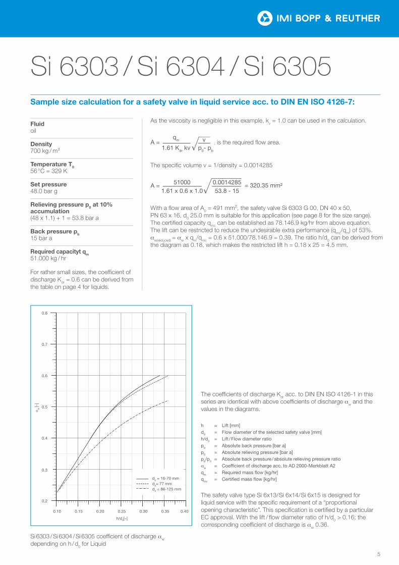
Si 6303 / Si 6304 / Si 6305 coe¦cient of discharge aw depending on h / d0 for Liquid
The coe¦cients of discharge Kdr acc. to DIN EN ISO 4126-1 in this series are identical with above coe¦cients of discharge aw and the values in the diagrams.
The safety valve type Si 6x13/ Si 6x14/ Si 6x15 is designed for liquid service with the specific requirement of a “proportional opening characteristic”. This specification is certified by a particular EC approval. With the lift / flow diameter ratio of h/d0 > 0.16; the corresponding coe¦cient of discharge is aw 0.36.
h = Lift [mm]d0 = Flow diameter of the selected safety valve [mm]h/d0 = Lift / Flow diameter ratiopb = Absolute back pressure [bar a]p0 = Absolute relieving pressure [bar a]pb/p0 = Absolute back pressure / absolute relieving pressure ratioaw = Coefficient of discharge acc. to AD 2000-Merkblatt A2qm = Required mass flow [kg/hr]qmc = Certified mass flow [kg/hr]
0.2
0.3
0.4
0.5
0.6
0.7
0.8
0.10 0.15 0.20 0.25 0.30 0.35 0.40
αw
[−]
h/d0 [−]
0.2
0.3
0.4
0.5
0.6
0.7
0.8
0.10 0.15 0.20 0.25 0.30 0.35 0.400.10 0.15 0.20 0.25 0.30 0.35 0.40
h/d0[–]
0.8
0.7
0.6
0.5
0.4
0.3
0.2
d0 = 16-70 mm d0= 77 mm d0 = 86-125 mm
aw
[–]
Fluid oil
Density700 kg / m³
Temperature T056 °C = 329 K
Set pressure48.0 bar g
Relieving pressure p0 at 10% accumulation(48 x 1.1) + 1 = 53.8 bar a
Back pressure pb15 bar a
Required capacityt qm51.000 kg / hr
For rather small sizes, the coe¦cient of discharge Kdr = 0.6 can be derived from the table on page 4 for liquids.
Sample size calculation for a safety valve in liquid service acc. to DIN EN ISO 4126-7:
With a flow area of A0 = 491 mm², the safety valve Si 6303 G 00, DN 40 x 50, PN 63 x 16, d0 25.0 mm is suitable for this application (see page 8 for the size range). The certified capacity qmc can be established as 78.146.9 kg/hr from above equation. The lift can be restricted to reduce the undesirable extra performance (qmc/qm) of 53%. aw(reduced) = aw x qm/qmc = 0.6 x 51.000/78.146.9 = 0.39. The ratio h/d0 can be derived from the diagram as 0.18, which makes the restricted lift h = 0.18 x 25 = 4.5 mm.
The specific volume v = 1/density = 0.0014285
A = qm
1.61 Kdr kv
v p0- pb
A = 51000 0.0014285 1.61 x 0.6 x 1.0 53.8 - 15
= 320.35 mm²
As the viscosity is negligible in this example, kv = 1.0 can be used in the calculation.
, is the required flow area.
6
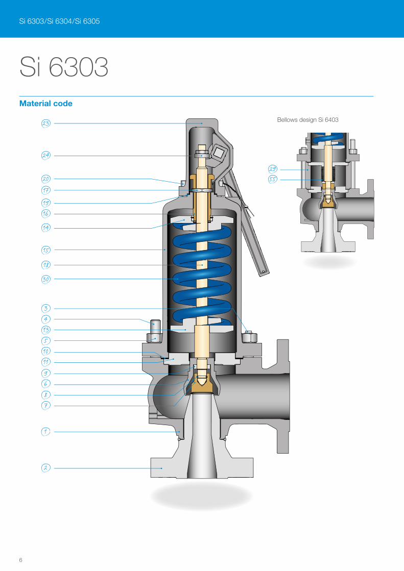
Si 6303
23
24
2017
1916
14
15
18
30
341351011
9687
2955
1
2
Si 6303 / Si 6304 / Si 6305
Bellows design Si 6403
Material code
7
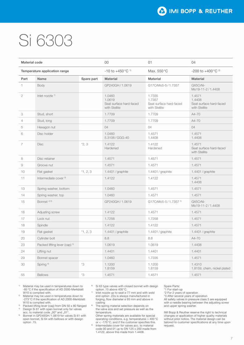
Si 6303Material code 00 01 04
Temperature application range -10 to +450 °C 1) Max. 550 °C -200 to +400 °C 2)
Part Name Spare part Material Material Material
1 Body GP240GH / 1.0619 G17CrMo5-5 / 1.7357 GX5CrNi-Mo19-11-2 / 1.4408
2 Inlet nozzle 7) 1.0460 1.0619 Seat surface hard-faced with Stellite
1.7335 1.7357 Seat surface hard-faced with Stellite
1.4571 1.4408 Seat surface hard-faced with Stellite
3 Stud, short 1.7709 1.7709 A4-70
4 Stud, long 1.7709 1.7709 A4-70
5 Hexagon nut 04 04 04
6 Disc holder 1.0460 5.3106 / GGG-40
1.4571 1.4408
1.4571 1.4408
7 Disc *2, 3 1.4122 Hardened
1.4122 Hardened
1.4571 Seat surface hard-faced with Stellite
8 Disc retainer 1.4571 1.4571 1.4571
9 Groove nut 1.4571 1.4571 1.4571
10 Flat gasket *1, 2, 3 1.4401 / graphite 1.4401 / graphite 1.4401 / graphite
11 Intermediate cover 9) 1.4122 1.4122 1.4571 1.4408
13 Spring washer, bottom 1.0460 1.4571 1.4571
14 Spring washer, top 1.0460 1.4571 1.4571
15 Bonnet 4) 6) GP240GH / 1.0619 G17CrMo5-5 / 1.7357 5) GX5CrNi-Mo19-11-2 / 1.4408
16 Adjusting screw 1.4122 1.4571 1.4571
17 Lock nut 1.7258 1.7258 1.4571
18 Spindle 1.4122 1.4122 1.4571
19 Flat gasket *1, 2, 3 1.4401 / graphite 1.4401 / graphite 1.4401 / graphite
20 Cylinder bolt 8.8 8.8 A4-70
23 Packed lifting lever (cap) 3) 1.0619 1.0619 1.4408
24 Lifting nut 1.4401 1.4401 1.4401
29 Bonnet spacer 1.0460 1.7335 1.4571
30 Spring 8) *3 1.1200 1.8159
1.1200 1.8159
1.4310 1.8159, chem. nickel plated
55 Bellows *3 1.4571 1.4571 1.4571
1) Material may be used in temperatures down to -85 °C if the specification of AD 2000-Merkblatt W10 is complied with.
2) Material may be used in temperatures down to -273 °C if the specification of AD 2000-Merkblatt W10 is complied with.
3) Packed lifting lever (cap) from DN 50 x 80 flanged 4) Design Si 61 with open bonnet only for valves
acc. to material code „00“ and „01“.5) Bonnet in GP240GH / 1.0619 for valves Si 61 with
open bonnet, Si 64 with bellows or with design option .15.
6) Si 63 type valves with closed bonnet with design option .15 above 400 °C.
7) Inlet nozzle up to seat ø 77 mm and with weld end option .22a is always manufactured in forging, flow diameter ø 93 mm and above in casting
8) The spring material selection depends on the valve size and set pressure as well as the temperature. Other spring materials are available for special operating conditions, e.g. temperatures > 400 °C or < -170 °C, and if the customer specifies this.
9) Intermediate cover for valves acc. to material code 00 and 01 up to DN 125 x 200 made from 1.4122, above this made from 1.4408.
Spare Parts:*1 For start-up*2 For 2 years of operation*3 After several years of operation All safety valves in pressure class 5 are equipped with a needle bearing between the adjusting screw and upper spring washer.
IMI Bopp & Reuther reserve the right to technical changes or application of higher quality materials without prior notice. The material design can be tailored to customer specifications at any time upon request.
8
Si 6303
Si 6303 / Si 6304 / Si 6305
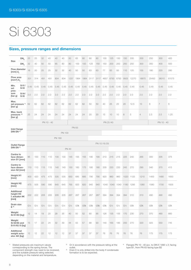
1) Stated pressures are maximum values corresponding to the spring forces. The component strength may need to be reviewed, and the suitable pressure rating selected, depending on the material and temperature.
2) Or in accordance with the pressure rating at the outlet.
3) Drain E is only drilled into the body if condensate formation is to be expected.
4) Flanges PN 10 - 40 acc. to DIN E 1092 x 2; facing type B1, from PN 63 facing type B2
SizeDNE 25 25 32 40 40 40 50 65 80 80 80 100 125 150 150 200 200 250 300 400
DNA32 40 50 50 65 80 80 100 100 125 150 150 200 200 250 250 300 350 400 500
Flow diameter [mm] d0
16 20 25 25 32 32 40 50 50 63 63 77 93 93 110 125 155 180 220 280
Flow area [mm²] A0
201 314 491 491 804 804 1257 1964 1964 3117 3117 4657 6793 6793 9503 12270 18870 25450 38010 61575
Min. set pres-sure [bar g]
Si 61 / Si 63
0.45 0.45 0.45 0.45 0.45 0.45 0.45 0.45 0.45 0.45 0.45 0.45 0.45 0.45 0.45 0.45 0.45 0.45 0.45 0.45
Si 64 / Si 65
2.0 2.0 2.0 2.0 2.0 2.0 2.0 2.0 2.0 2.0 2.0 2.0 2.0 2.0 2.0 2.0 2.0 2.0 2.0 2.0
Max. set pressure 1)
[bar g]62 62 62 62 62 62 62 62 62 50 50 40 25 25 20 12.5 10 8 7 6
Max. back pressure 2) [bar g]
25 24 24 24 24 24 24 24 24 20 20 15 10 10 8 5 4 2.5 2.5 1.25
Inlet flange DIN EN 4)
PN 10 - 40 PN 25 /40 PN 10 - 40
PN 63
PN 100
PN 160
Outlet flange DIN EN 4)
PN 10 /16 /25
PN 40
Centre to face dimen-sion S1 [mm]
95 100 110 110 130 130 145 155 155 190 190 210 215 215 225 240 265 300 335 375
Centre to face dimen-sion S2 [mm]
110 110 115 115 140 140 150 160 175 180 180 200 220 220 245 270 290 340 370 415
Height H1 [mm]
400 420 475 475 535 535 650 685 685 790 790 920 960 960 1020 1125 1210 1400 1480 1650
Height H2 [mm]
475 505 590 590 645 645 765 820 820 940 940 1040 1040 1040 1180 1295 1380 1580 1700 1835
Additional height H3 f. actuator AK [mm]
222 222 205 205 205 205 267 267 267 267 267 394 394 394 394 310 310 490 490 490
Drain size E 3) G¼ G¼ G¼ G¼ G¼ G¼ G¼ G3/8 G3/8 G3/8 G3/8 G3/8 G½ G½ G½ G3/4 G3/4 G3/4 G3/4 G3/4
Weight Si 61/63 [kg]
12 14 19 20 28 35 40 50 52 80 85 126 135 155 170 230 270 370 480 660
Weight Si 64/65 and Si 61/63.15 [kg]
15 17 22 24 32 39 44 55 57 88 93 140 165 185 200 270 320 325 550 745
Additional weight actu-ator AK [kg]
12 12 22 12 12 12 37 37 37 37 37 76 76 76 76 76 76 175 175 175
Sizes, pressure ranges and dimensions

9
Si 6303
B
A E
D
Lø
C
H3
H1
S1
S2
Si 6303 Si 6103
Si 6403 Si 6503
H2
S1
S2
K
Support brackets
Size DNE × DNA
A B C D E LSupport bracket thickness
Number of screws
40 x 65 186 93 140 70 156 14 12 4 x M 12
50 x 80 210 95 165 70 180 14 12 4 x M 12
65 x 100 250 95 205 70 220 14 12 4 x M 12
80 x 125 295 120 240 90 260 18 15 4 x M 16
100 x 150 320 120 265 90 285 18 15 4 x M 16
125 x 200 365 120 300 90 330 18 15 4 x M 16
150 x 250 415 150 360 120 380 18 15 4 x M 16
200 x 250 455 180 400 150 420 18 15 4 x M 16
200 x 300 510 180 450 150 470 23 20 4 x M 20
250 x 350 620 190 560 160 580 23 20 4 x M 20
300 x 400 695 210 600 180 655 23 20 4 x M 20
400 x 500 800 230 715 200 760 23 20 4 x M 20
The height from the inlet to the lower edge of the support bracket is identical with the centre to face dimension S2.
Support brackets will only be drilled if specified by the customer.
The bonnet for bellows seal design is provided with the test connection K. K up to DN 50 x 80 – G¼”, above G⅜”.
Dimensions in mm
Support brackets
Actuator AK
10
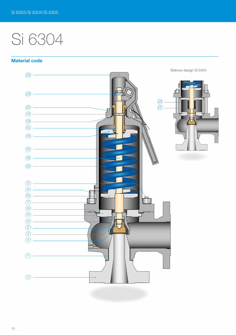
Si 6304
23
24
2017
1916
14
15
18
30
3413510119687
1
2
2955
Si 6303 / Si 6304 / Si 6305
Bellows design Si 6404
Material code
11
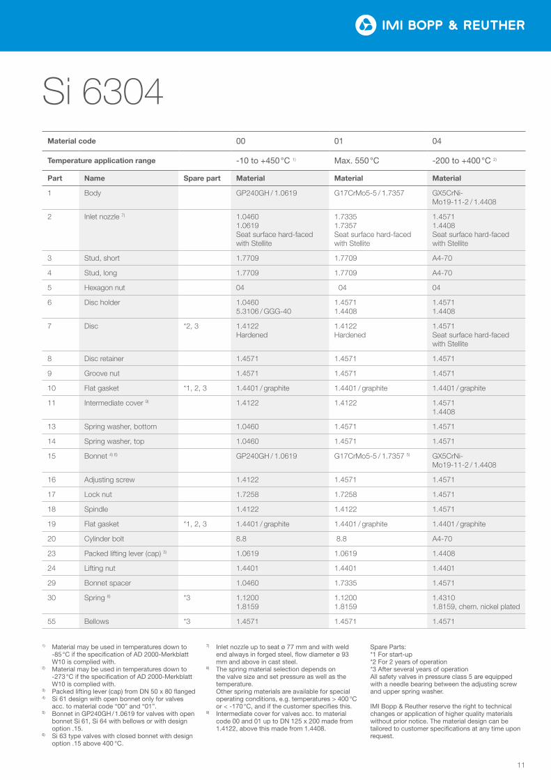
Si 6304Material code 00 01 04
Temperature application range -10 to +450 °C 1) Max. 550 °C -200 to +400 °C 2)
Part Name Spare part Material Material Material
1 Body GP240GH / 1.0619 G17CrMo5-5 / 1.7357 GX5CrNi-Mo19-11-2 / 1.4408
2 Inlet nozzle 7) 1.0460 1.0619 Seat surface hard-faced with Stellite
1.7335 1.7357 Seat surface hard-faced with Stellite
1.4571 1.4408 Seat surface hard-faced with Stellite
3 Stud, short 1.7709 1.7709 A4-70
4 Stud, long 1.7709 1.7709 A4-70
5 Hexagon nut 04 04 04
6 Disc holder 1.0460 5.3106 / GGG-40
1.4571 1.4408
1.4571 1.4408
7 Disc *2, 3 1.4122 Hardened
1.4122 Hardened
1.4571 Seat surface hard-faced with Stellite
8 Disc retainer 1.4571 1.4571 1.4571
9 Groove nut 1.4571 1.4571 1.4571
10 Flat gasket *1, 2, 3 1.4401 / graphite 1.4401 / graphite 1.4401 / graphite
11 Intermediate cover 9) 1.4122 1.4122 1.4571 1.4408
13 Spring washer, bottom 1.0460 1.4571 1.4571
14 Spring washer, top 1.0460 1.4571 1.4571
15 Bonnet 4) 6) GP240GH / 1.0619 G17CrMo5-5 / 1.7357 5) GX5CrNi-Mo19-11-2 / 1.4408
16 Adjusting screw 1.4122 1.4571 1.4571
17 Lock nut 1.7258 1.7258 1.4571
18 Spindle 1.4122 1.4122 1.4571
19 Flat gasket *1, 2, 3 1.4401 / graphite 1.4401 / graphite 1.4401 / graphite
20 Cylinder bolt 8.8 8.8 A4-70
23 Packed lifting lever (cap) 3) 1.0619 1.0619 1.4408
24 Lifting nut 1.4401 1.4401 1.4401
29 Bonnet spacer 1.0460 1.7335 1.4571
30 Spring 8) *3 1.1200 1.8159
1.1200 1.8159
1.4310 1.8159, chem. nickel plated
55 Bellows *3 1.4571 1.4571 1.4571
1) Material may be used in temperatures down to -85 °C if the specification of AD 2000-Merkblatt W10 is complied with.
2) Material may be used in temperatures down to -273 °C if the specification of AD 2000-Merkblatt W10 is complied with.
3) Packed lifting lever (cap) from DN 50 x 80 flanged 4) Si 61 design with open bonnet only for valves
acc. to material code “00” and “01”.5) Bonnet in GP240GH / 1.0619 for valves with open
bonnet Si 61, Si 64 with bellows or with design option .15.
6) Si 63 type valves with closed bonnet with design option .15 above 400 °C.
7) Inlet nozzle up to seat ø 77 mm and with weld end always in forged steel, flow diameter ø 93 mm and above in cast steel.
8) The spring material selection depends on the valve size and set pressure as well as the temperature. Other spring materials are available for special operating conditions, e.g. temperatures > 400 °C or < -170 °C, and if the customer specifies this.
9) Intermediate cover for valves acc. to material code 00 and 01 up to DN 125 x 200 made from 1.4122, above this made from 1.4408.
Spare Parts:*1 For start-up*2 For 2 years of operation*3 After several years of operationAll safety valves in pressure class 5 are equipped with a needle bearing between the adjusting screw and upper spring washer.
IMI Bopp & Reuther reserve the right to technical changes or application of higher quality materials without prior notice. The material design can be tailored to customer specifications at any time upon request.
12
Si 6304
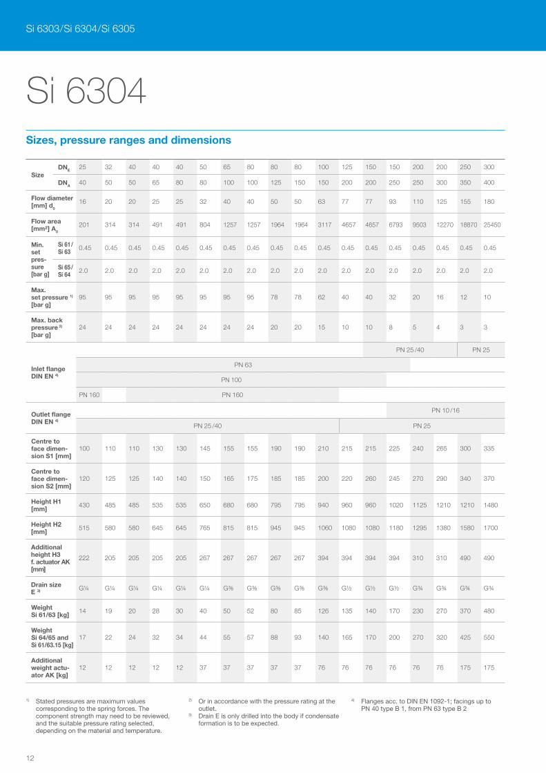
Si 6303 / Si 6304 / Si 6305
SizeDNE 25 32 40 40 40 50 65 80 80 80 100 125 150 150 200 200 250 300
DNA40 50 50 65 80 80 100 100 125 150 150 200 200 250 250 300 350 400
Flow diameter [mm] d0
16 20 20 25 25 32 40 40 50 50 63 77 77 93 110 125 155 180
Flow area [mm²] A0
201 314 314 491 491 804 1257 1257 1964 1964 3117 4657 4657 6793 9503 12270 18870 25450
Min. set pres-sure [bar g]
Si 61 / Si 63
0.45 0.45 0.45 0.45 0.45 0.45 0.45 0.45 0.45 0.45 0.45 0.45 0.45 0.45 0.45 0.45 0.45 0.45
Si 65 / Si 64
2.0 2.0 2.0 2.0 2.0 2.0 2.0 2.0 2.0 2.0 2.0 2.0 2.0 2.0 2.0 2.0 2.0 2.0
Max. set pressure 1)
[bar g]95 95 95 95 95 95 95 95 78 78 62 40 40 32 20 16 12 10
Max. back pressure 2) [bar g]
24 24 24 24 24 24 24 24 20 20 15 10 10 8 5 4 3 3
Inlet flange DIN EN 4)
PN 25 /40 PN 25
PN 63
PN 100
PN 160 PN 160
Outlet flange DIN EN 4)
PN 10 /16
PN 25 /40 PN 25
Centre to face dimen-sion S1 [mm]
100 110 110 130 130 145 155 155 190 190 210 215 215 225 240 265 300 335
Centre to face dimen-sion S2 [mm]
120 125 125 140 140 150 165 175 185 185 200 220 260 245 270 290 340 370
Height H1 [mm]
430 485 485 535 535 650 680 680 795 795 940 960 960 1020 1125 1210 1210 1480
Height H2 [mm]
515 580 580 645 645 765 815 815 945 945 1060 1080 1080 1180 1295 1380 1580 1700
Additional height H3 f. actuator AK [mm]
222 205 205 205 205 267 267 267 267 267 394 394 394 394 310 310 490 490
Drain size E 3) G¼ G¼ G¼ G¼ G¼ G¼ G⅜ G⅜ G⅜ G⅜ G⅜ G½ G½ G½ G¾ G¾ G¾ G¾
Weight Si 61/63 [kg]
14 19 20 28 30 40 50 52 80 85 126 135 140 170 230 270 370 480
Weight Si 64/65 and Si 61/63.15 [kg]
17 22 24 32 34 44 55 57 88 93 140 165 170 200 270 320 425 550
Additional weight actu-ator AK [kg]
12 12 12 12 12 37 37 37 37 37 76 76 76 76 76 76 175 175
1) Stated pressures are maximum values corresponding to the spring forces. The component strength may need to be reviewed, and the suitable pressure rating selected, depending on the material and temperature.
2) Or in accordance with the pressure rating at the outlet.
3) Drain E is only drilled into the body if condensate formation is to be expected.
4) Flanges acc. to DIN EN 1092-1; facings up to PN 40 type B 1, from PN 63 type B 2
Sizes, pressure ranges and dimensions
13
Si 6304
B
A E
D
Lø
C
H3
H1
S1
S2
Si 6304 Si 6104
Si 6404 Si 6504
H2
S1
S2
K
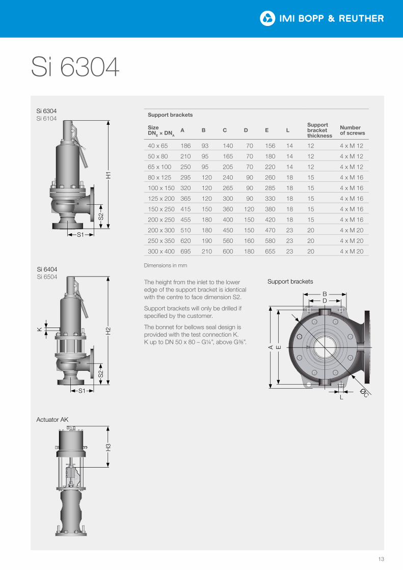
Support brackets
Size DNE × DNA
A B C D E LSupport bracket thickness
Number of screws
40 x 65 186 93 140 70 156 14 12 4 x M 12
50 x 80 210 95 165 70 180 14 12 4 x M 12
65 x 100 250 95 205 70 220 14 12 4 x M 12
80 x 125 295 120 240 90 260 18 15 4 x M 16
100 x 150 320 120 265 90 285 18 15 4 x M 16
125 x 200 365 120 300 90 330 18 15 4 x M 16
150 x 250 415 150 360 120 380 18 15 4 x M 16
200 x 250 455 180 400 150 420 18 15 4 x M 16
200 x 300 510 180 450 150 470 23 20 4 x M 20
250 x 350 620 190 560 160 580 23 20 4 x M 20
300 x 400 695 210 600 180 655 23 20 4 x M 20
The height from the inlet to the lower edge of the support bracket is identical with the centre to face dimension S2.
Support brackets will only be drilled if specified by the customer.
The bonnet for bellows seal design is provided with the test connection K. K up to DN 50 x 80 – G¼”, above G⅜”.
Dimensions in mm
Support brackets
Actuator AK
14
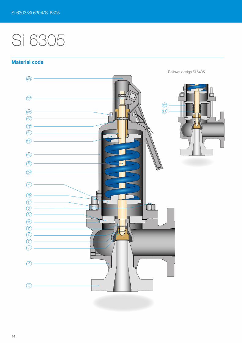
Si 6305
23
24
20
17
1916
14
15
18
30
4
135310
119687
1
2
2955
Si 6303 / Si 6304 / Si 6305
Bellows design Si 6405
Material code
15
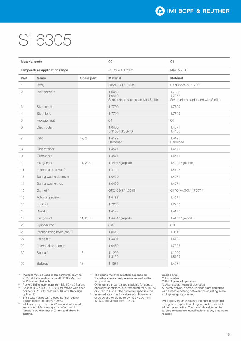
Si 6305Material code 00 01
Temperature application range -10 to + 450 °C 1) Max. 550 °C
Part Name Spare part Material Material
1 Body GP240GH / 1.0619 G17CrMo5-5 / 1.7357
2 Inlet nozzle 5) 1.0460 1.0619 Seat surface hard-faced with Stellite
1.7335 1.7357 Seat surface hard-faced with Stellite
3 Stud, short 1.7709 1.7709
4 Stud, long 1.7709 1.7709
5 Hexagon nut 04 04
6 Disc holder 1.0460 5.3106 / GGG-40
1.4571 1.4408
7 Disc *2, 3 1.4122 Hardened
1.4122 Hardened
8 Disc retainer 1.4571 1.4571
9 Groove nut 1.4571 1.4571
10 Flat gasket *1, 2, 3 1.4401 / graphite 1.4401 / graphite
11 Intermediate cover 7) 1.4122 1.4122
13 Spring washer, bottom 1.0460 1.4571
14 Spring washer, top 1.0460 1.4571
15 Bonnet 4) GP240GH / 1.0619 G17CrMo5-5 / 1.7357 3)
16 Adjusting screw 1.4122 1.4571
17 Locknut 1.7258 1.7258
18 Spindle 1.4122 1.4122
19 Flat gasket *1, 2, 3 1.4401 / graphite 1.4401 / graphite
20 Cylinder bolt 8.8 8.8
23 Packed lifting lever (cap) 2) 1.0619 1.0619
24 Lifting nut 1.4401 1.4401
29 Intermediate spacer 1.0460 1.7335
30 Spring 6) *3 1.1200 1.8159
1.1200 1.8159
55 Bellows *3 1.4571 1.4571
1) Material may be used in temperatures down to -85 °C if the specification of AD 2000-Merkblatt W10 is complied with.
2) Packed lifting lever (cap) from DN 50 x 80 flanged3) Bonnet in GP240GH / 1.0619 for valves with open
bonnet Si 61, with bellows Si 64 or with design option .15.
4) Si 63 type valves with closed bonnet require design option .15 above 400 °C.
5) Inlet nozzle up to seat ø 77 mm and with weld end option .22a is always manufactured in forging, flow diameter ø 93 mm and above in casting.
6) The spring material selection depends on the valve size and set pressure as well as the temperature. Other spring materials are available for special operating conditions, e.g. temperatures > 400 °C or < -170 °C, and if the customer specifies this.
7) Intermediate cover for valves acc. to material code 00 and 01 up up to DN 125 x 200 from 1.4122, above this from 1.4408.
Spare Parts:*1 For start-up*2 For 2 years of operation*3 After several years of operationAll safety valves in pressure class 5 are equipped with a needle bearing between the adjusting screw and upper spring washer.
IMI Bopp & Reuther reserve the right to technical changes or application of higher quality materials without prior notice. The material design can be tailored to customer specifications at any time upon request.
16
Si 6305
Si 6303 / Si 6304 / Si 6305
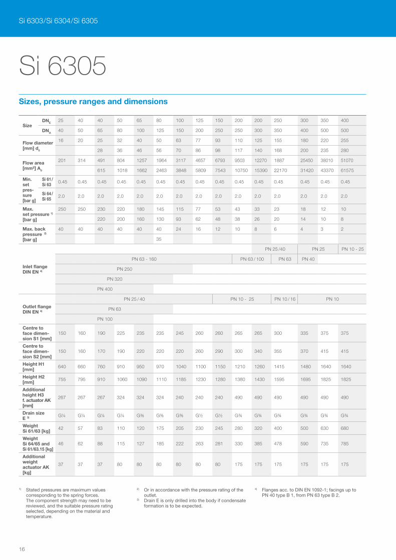
SizeDNE 25 40 40 50 65 80 100 125 150 200 200 250 300 350 400
DNA40 50 65 80 100 125 150 200 250 250 300 350 400 500 500
Flow diameter [mm] d0
16 20 25 32 40 50 63 77 93 110 125 155 180 220 255
28 36 46 56 70 86 98 117 140 168 200 235 280
Flow area [mm²] A0
201 314 491 804 1257 1964 3117 4657 6793 9503 12270 1887 25450 38010 51070
615 1018 1662 2463 3848 5809 7543 10750 15390 22170 31420 43370 61575
Min. set pres-sure [bar g]
Si 61 / Si 63
0.45 0.45 0.45 0.45 0.45 0.45 0.45 0.45 0.45 0.45 0.45 0.45 0.45 0.45 0.45
Si 64 / Si 65
2.0 2.0 2.0 2.0 2.0 2.0 2.0 2.0 2.0 2.0 2.0 2.0 2.0 2.0 2.0
Max. set pressure 1)
[bar g]
250 250 230 220 180 145 115 77 53 43 33 23 18 12 10
220 200 160 130 93 62 48 38 26 20 14 10 8
Max. back pressure 2) [bar g]
40 40 40 40 40 40 24 16 12 10 8 6 4 3 2
35
Inlet flange DIN EN 4)
PN 25 /40 PN 25 PN 10 - 25
PN 63 - 160 PN 63 / 100 PN 63 PN 40
PN 250
PN 320
PN 400
Outlet flange DIN EN 4)
PN 25 / 40 PN 10 - 25 PN 10 / 16 PN 10
PN 63
PN 100
Centre to face dimen-sion S1 [mm]
150 160 190 225 235 235 245 260 260 265 265 300 335 375 375
Centre to face dimen-sion S2 [mm]
150 160 170 190 220 220 220 260 290 300 340 355 370 415 415
Height H1 [mm]
640 660 760 910 950 970 1040 1100 1150 1210 1260 1415 1480 1640 1640
Height H2 [mm]
755 795 910 1060 1090 1110 1185 1230 1280 1380 1430 1595 1695 1825 1825
Additional height H3 f. actuator AK [mm]
267 267 267 324 324 324 240 240 240 490 490 490 490 490 490
Drain size E 3) G¼ G¼ G¼ G¼ G⅜ G⅜ G⅜ G½ G½ G¾ G¾ G¾ G¾ G¾ G¾
Weight Si 61/63 [kg]
42 57 83 110 120 175 205 230 245 280 320 400 500 630 680
Weight Si 64/65 and Si 61/63.15 [kg]
46 62 88 115 127 185 222 263 281 330 385 478 590 735 785
Additional weight actuator AK [kg]
37 37 37 80 80 80 80 80 80 175 175 175 175 175 175
1) Stated pressures are maximum values corresponding to the spring forces. The component strength may need to be reviewed, and the suitable pressure rating selected, depending on the material and temperature.
2) Or in accordance with the pressure rating of the outlet.
3) Drain E is only drilled into the body if condensate formation is to be expected.
4) Flanges acc. to DIN EN 1092-1; facings up to PN 40 type B 1, from PN 63 type B 2.
Sizes, pressure ranges and dimensions
17
B
A E
D
Lø
C
H3
H1
S1
S2
Si 6305 Si 6105
Si 6405 Si 6505
H2
S1
S2
K
Si 6305
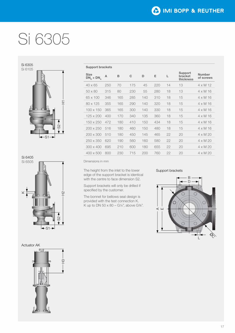
Support brackets
Size DNE × DNA
A B C D E LSupport bracket thickness
Number of screws
40 x 65 250 70 175 45 220 14 13 4 x M 12
50 x 80 315 80 230 55 280 18 13 4 x M 16
65 x 100 346 165 285 140 310 18 15 4 x M 16
80 x 125 355 165 290 140 320 18 15 4 x M 16
100 x 150 365 165 300 140 330 18 15 4 x M 16
125 x 200 400 170 340 135 360 18 15 4 x M 16
150 x 250 472 180 410 150 434 18 15 4 x M 16
200 x 250 516 180 460 150 480 18 15 4 x M 16
200 x 300 510 180 450 145 465 22 20 4 x M 20
250 x 350 620 190 560 160 580 22 20 4 x M 20
300 x 400 695 210 600 180 655 22 20 4 x M 20
400 x 500 800 230 715 200 760 22 20 4 x M 20
The height from the inlet to the lower edge of the support bracket is identical with the centre to face dimension S2.
Support brackets will only be drilled if specified by the customer.
The bonnet for bellows seal design is provided with the test connection K. K up to DN 50 x 80 – G¼”, above G⅜”.
Dimensions in mm
Support brackets
Actuator AK
IMI Critical Engineering Lakeside, Solihull Parkway Birmingham Business Park Birmingham B37 7XZ United Kingdom
Tel: +44 (0)121 717 3700 Fax: +44 (0)121 717 3701
www.imi-critical.com
IMI Bopp & Reuther Bopp & Reuther Sicherheits- und Regelarmaturen GmbH Carl-Reuther-Straße 1 68305 Mannheim Deutschland
Tel: +49 (0)621 76220-100 Fax: +49 (0)621 76220-120
www.imi-critical.com [email protected]
IMI B
uR /
Si 6
303
/ Si 6
304
/ Si 6
305
/ en
/ 0
2_20
18