Shock Loading and Failure of Fluid-Filled Tubular...
41
Shock Loading and Failure of Fluid-Filled Tubular Structures Joseph E. Shepherd and Kazuaki Inaba Abstract We consider the response of fluid-filled tubes to internal shock waves and explosions. The emphasis is on the fluid-solid coupling aspects. The coupling of axial wave propagation in the fluid to flexural waves in the tube may be char- acterized by a single parameter that depends only on the tube and fluid material properties and dimensions. Using this parameter as a figure of merit, we discuss the limiting cases of weak and strong coupling between the fluid wave motion and tube structural motion. Examples discussed include detonation and shock waves in gas and liquid-filled tubes of metal, polymers, and composites. The results of experi- ments on elastic and plastic deformation are presented as well as selected results on fracture and rupture. Detonation in gas-filled tubes usually falls in the weak cou- pling regime except for very thin tubes or cases of deformation that lead to tube rupture. Impact generated axial waves in liquid-filled tubes can range from weak- to-strong coupling cases depending on the tube wall thickness and material. These cases include the well-known phenomenon of water hammer and we describe the relationship of impact studies to previous work on wave-propagation in water-filled pipes. 1 Introduction Dynamic loading of fluid-filled tubes is a situation that is encountered in industrial hazard analysis and studied in the laboratory as a model fluid-solid coupling prob- lem. Propagating explosions or shock waves can occur inside piping systems con- Joseph E. Shepherd California Institute of Technology, Pasadena, CA USA 91125 e-mail: joseph.e.shepherd@ caltech.edu Kuzuaki Inaba Tokyo Institute of Technology2-12-1 Ookayama, Meguro-ku, Tokyo, 152-8550, JAPAN e-mail: [email protected] 1
Transcript of Shock Loading and Failure of Fluid-Filled Tubular...

Shock Loading and Failure of Fluid-FilledTubular Structures
Joseph E. Shepherd and Kazuaki Inaba
Abstract We consider the response of fluid-filled tubes to internal shock wavesand explosions. The emphasis is on the fluid-solid coupling aspects. The couplingof axial wave propagation in the fluid to flexural waves in the tube may be char-acterized by a single parameter that depends only on the tubeand fluid materialproperties and dimensions. Using this parameter as a figure of merit, we discuss thelimiting cases of weak and strong coupling between the fluid wave motion and tubestructural motion. Examples discussed include detonationand shock waves in gasand liquid-filled tubes of metal, polymers, and composites.The results of experi-ments on elastic and plastic deformation are presented as well as selected results onfracture and rupture. Detonation in gas-filled tubes usually falls in the weak cou-pling regime except for very thin tubes or cases of deformation that lead to tuberupture. Impact generated axial waves in liquid-filled tubes can range from weak-to-strong coupling cases depending on the tube wall thickness and material. Thesecases include the well-known phenomenon of water hammer andwe describe therelationship of impact studies to previous work on wave-propagation in water-filledpipes.
1 Introduction
Dynamic loading of fluid-filled tubes is a situation that is encountered in industrialhazard analysis and studied in the laboratory as a model fluid-solid coupling prob-lem. Propagating explosions or shock waves can occur insidepiping systems con-
Joseph E. ShepherdCalifornia Institute of Technology, Pasadena, CA USA 91125e-mail:[email protected]
Kuzuaki InabaTokyo Institute of Technology2-12-1 Ookayama, Meguro-ku,Tokyo, 152-8550, JAPAN e-mail:[email protected]
1
Joe Shepherd
Typewritten Text
Joe Shepherd
Typewritten Text
Joe Shepherd
Typewritten Text
Chapter 6, pp. 153-190 of Dynamic Failure of Materials and Structures, Editors Arun Shukla, Guruswami Ravichandran, Y. Rajapakse, Springer, 2010. DOI 10.1007/978-1-4419-0446-1.
Joe Shepherd
Typewritten Text
Joe Shepherd
Typewritten Text
Joe Shepherd
Typewritten Text
2 Joseph E. Shepherd and Kazuaki Inaba
taining explosive gases and laboratory combustion facilities (Shepherd, 2009). Acommon situation is piping filled with water or steam and dynamic loading createdby valve actuation - this is the known as “water hammer”, a well-known problemin power and process plants (Wylie and Streeter, 1993, Watters, 1984). Gas-filledand liquid-filled pipes represent extreme situations from the viewpoint of fluid-solidcoupling. Gas-filled pipes represent the case of weak or one-way coupling with gasmotion forcing the structural response of the pipe but relatively little or no gas mo-tion is caused by the piping structural deformation. There is an extensive discussionof this case in Shepherd (2009) and a few representative cases are presented in thisreview to illustrate the features of the weak coupling case.Liquid-filled thin-walltubes represent the case of strong or two-way coupling in which the fluid motionand structural response of the pipe must be treated simultaneously. We focus almostexclusively on the strong coupling case in the present review.
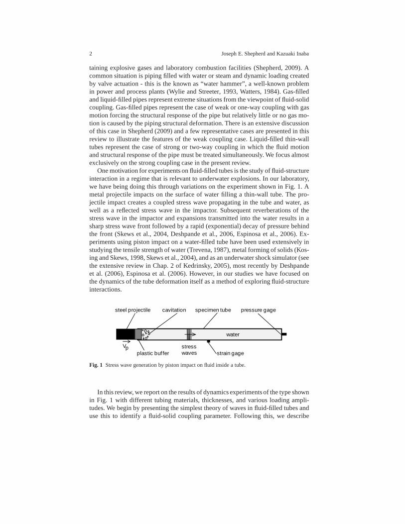
One motivation for experiments on fluid-filled tubes is the study of fluid-structureinteraction in a regime that is relevant to underwater explosions. In our laboratory,we have being doing this through variations on the experiment shown in Fig. 1. Ametal projectile impacts on the surface of water filling a thin-wall tube. The pro-jectile impact creates a coupled stress wave propagating inthe tube and water, aswell as a reflected stress wave in the impactor. Subsequent reverberations of thestress wave in the impactor and expansions transmitted intothe water results in asharp stress wave front followed by a rapid (exponential) decay of pressure behindthe front (Skews et al., 2004, Deshpande et al., 2006, Espinosa et al., 2006). Ex-periments using piston impact on a water-filled tube have been used extensively instudying the tensile strength of water (Trevena, 1987), metal forming of solids (Kos-ing and Skews, 1998, Skews et al., 2004), and as an underwatershock simulator (seethe extensive review in Chap. 2 of Kedrinsky, 2005), most recently by Deshpandeet al. (2006), Espinosa et al. (2006). However, in our studies we have focused onthe dynamics of the tube deformation itself as a method of exploring fluid-structureinteractions.
steel projectile
plastic buf fer
water
specimen tube
strain gagestresswaves
Vp
pressure gagecavitation
Fig. 1 Stress wave generation by piston impact on fluid inside a tube.
In this review, we report on the results of dynamics experiments of the type shownin Fig. 1 with different tubing materials, thicknesses, andvarious loading ampli-tudes. We begin by presenting the simplest theory of waves influid-filled tubes anduse this to identify a fluid-solid coupling parameter. Following this, we describe

Shock Loading and Failure of Fluid-Filled Tubular Structures 3
more sophisticated models and the regimes corresponding tothe various values ofthe coupling parameter. Experimental results are presented for a number of differentcases in each of the regimes.
2 Korteweg Model of Wave Propagation
Classical water hammer theory (Skalak, 1956, Tijsseling, 1996, Wiggert and Tijs-seling, 2001) considers the coupling of the motion of an elastic pipe or tube withacoustic waves propagating in the water within the pipe. Various levels of theoreticaltreatment are possible (see Junger and Feit, 1986, Howe, 1998, for the foundationsof fluid-structure interaction) but the key physical effects can be predicted by thevery simple model proposed by Korteweg (1878) and confirmed experimentally byJoukowsky (1900) (see the historical review in Tijsseling,1996) in which the pres-sures generated by the acoustic waves in the water are balanced by static stress inthe surrounding pipe, considering purely elastic radial deflection uncoupled fromthe longitudinal motion.
The Korteweg model reproduces the essential features of classical water hammerexperiments with minimal assumptions. The fluid in the tube is compressible with adensityρ f and sound speedaf , and the motions in the fluid are treated as quasi-onedimensional. The equations of motion of the fluid (Lighthill, 1978) are continuity(mass conservation)
∂∂ t
(ρA)+∂∂x
(ρuA) = 0 , (1)
ρ∂u∂ t
+ρu∂u∂x
=−∂P∂x
, (2)
whereρ is the fluid density, u is the fluid velocity,A is the cross-sectional area of thetube, andP is the pressure. For small amplitude motions, we can consider pressureand density to be only slightly different from the at-rest values,
P′ = P−Po ≪ Po , (3)
ρ ′ = ρ −ρo ≪ ρo . (4)
The tube area changes are relatively small,
A′ = A−Ao ≪ Ao , (5)
and the velocity u is of the same order as these perturbations. Assuming isentropicmotion, the pressure and density perturbations are relatedby
P′ = a2f ρ
′ , (6)

4 Joseph E. Shepherd and Kazuaki Inaba
where the sound speed for the fluid is
a2f =
(∂P∂ρ
)
s. (7)
Expanding the equations of motion (1 and 2), we obtain the pair of linear equations,
∂∂ t
(ρA)+ρoAo∂u∂x
= 0 , (8)
ρo∂u∂ t
=−∂P′
∂x. (9)
Cross-differentiating w.r.t. time and distance, and eliminating velocity, we can writethis as
∂ 2P′
∂x2 =1Ao
∂ 2
∂ t2 (ρA) . (10)
In order to complete the model, the tube area must be determined as functionof space and timeA(x, t). In general, this requires considering the dynamics of themotion of the tube (Skalak, 1956). The Korteweg approximation is to neglect theinertia and bending stiffness of the tube wall and only consider a force balance inthe hoop (θ ) direction
σθ =Rh
P′ , (11)
whereσθ is the hoop stress,h is the wall thickness, andR is the mean tube radius. Ingeneral, the hoop stress will be a function of all componentsof the strain in the tubewall and depend on the radial location. However, if we use thesimple membranemodel of hoop stress for a cylinder and neglect longitudinalcontributions, the hoopstrain and stress will be related by
εθ =σθE
, (12)
whereE is the Young’s modulus of the tube wall material and the hoop strain canbe computed from the change in mean radius as
εθ =R′
Ro, (13)
=12
A′
Ao. (14)
The pressure and area changes are then uniquely related

Shock Loading and Failure of Fluid-Filled Tubular Structures 5
A′ = Ao2Rh
P′
E. (15)
A generalization of this idea is to take the area of the tube asa function of pressureperturbation only, then
A= A(P′) , (16)
and we can write the perturbation equation (10) as a linear wave equation with awave speed that depends both on the fluid compressibility andtube extensibility.
Korteweg equation:
∂ 2P′
∂x2 =1c2
∂ 2P′
∂ t2 . (17)
Wave speed:
c−2 =1Ao
∂∂P′
(ρA) , (18)
=∂ρ∂P′
+ρAo
∂A∂P′
. (19)
The first term in (19) represents the response of the fluid to pressure changesand can be interpreted in terms of the fluid sound speed (7) andthe second termrepresents the response of the tube to pressure changes. Using the simple model ofa static hoop stress balance (15), we obtain the classical formula for wave speed inelastic pipes,
c−2 = a−2f +ρo
2REh
, (20)
which was first derived by Korteweg in 1878. The coupling between the tube andfluid can be more clearly seen by writing the wave speed as
c= af
[
1+
(
a2f
a2s
)(ρ f
ρs
)(2Rh
)]−1/2
, (21)
where the bar sound speed (Kolsky, 1963) for the tube material is
as =
√
Eρs
, (22)

6 Joseph E. Shepherd and Kazuaki Inaba
andρs is the density of the solid making up the tube. The speed of sound in the fluidaf is often expressed in terms of the fluid bulk modulusK f ,
K f =−υ(
∂P∂υ
)
s, af =
√
K f
ρ f. (23)
The wave equation (17) is an approximation to the governing equations for the mo-tion of a fluid-filled, thin-wall tube. More general considerations (Skalak, 1956,Fuller and Fahy, 1982, Pinnington, 1997) with fewer approximations result in acoupled system of fourth-order equations for radial and longitudinal motion of thetube considered as a shell and acoustic oscillations in the fluid, discussed in the nextsection. There are four types of axisymmetric modes: a longitudinal motion in theshell, a coupled radial-acoustic motion (Korteweg waves) that correspond to (17),and two shell bending modes. The individual modes of shell oscillation and acousticmotion in the fluid are transformed in a set of coupled modes (Del Grosso, 1971,Sinha et al., 1992, Lafleur and Shields, 1995), the precise nature of these depends onthe extent of fluid-solid coupling as discussed below. Only one of these modes, theKorteweg waves, is described by the present model (17). Properties relevant to theevaluation of the fluid-solid coupling are given in Table 1. The three terms identified
Table 1 Properties relevant to fluid-structure interaction for some representative materials.
Solids
material E ρs as
(GPa) (kg⋅m−3) (m/s)
steel 200 7.8×10³ 5000aluminum 69 2.7×10³ 5100PMMA 3.3 1.2×10³ *Polycarbonate 2.6 1.25×10³ *glass 96 2.6×10³ 6080GFRP 5–80 1.4-2.2×10³ *CFRP 5–400 1.5×10³ *
Fluids
material K f ρ f af
(GPa) (kg⋅m−3) (m/s)
water 2.2 1.0×10³ 1482mercury 28.2 13.45×10³ 1450air 0.14 MPa 1.2 343* Polymers are viscoelastic and composites are highlyanisotropic so that there is no single well-defined bar speedforthese cases.
Shock Loading and Failure of Fluid-Filled Tubular Structures 7
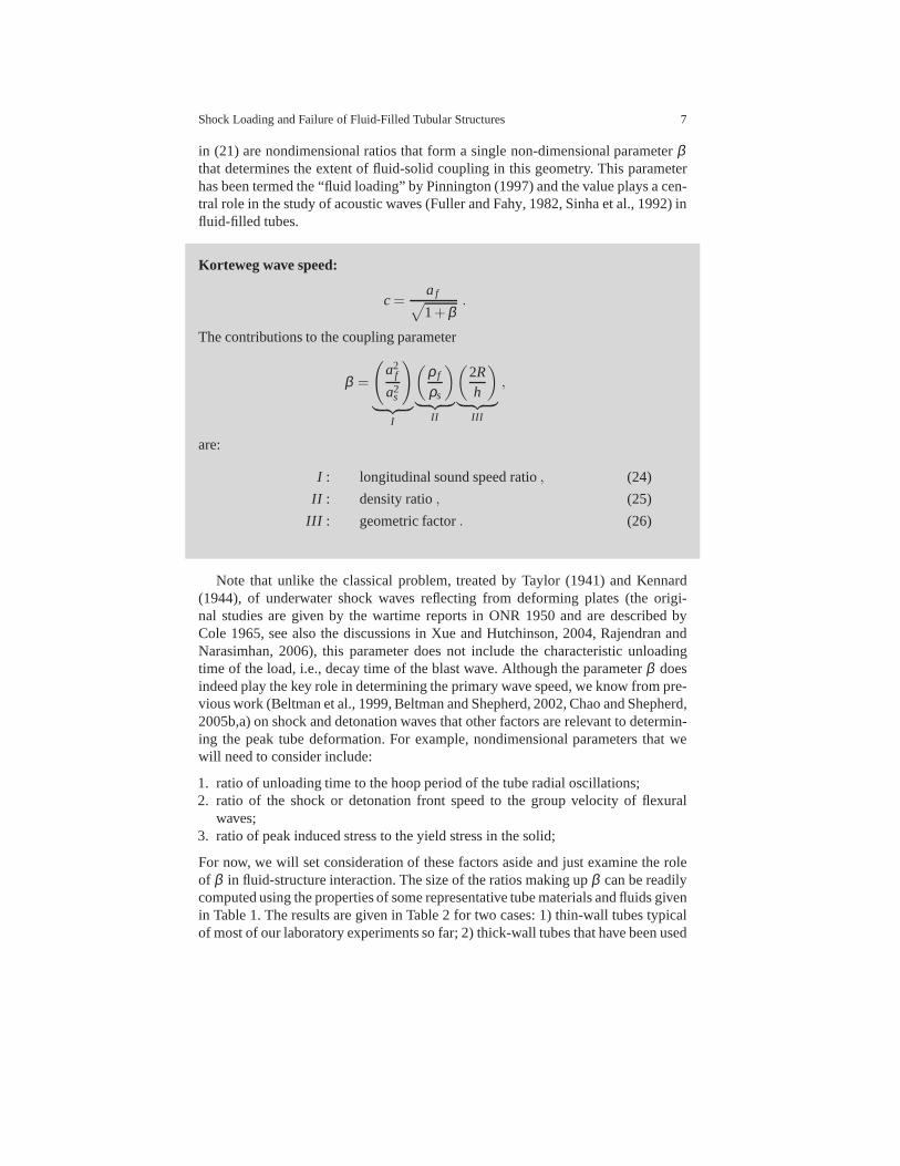
in (21) are nondimensional ratios that form a single non-dimensional parameterβthat determines the extent of fluid-solid coupling in this geometry. This parameterhas been termed the “fluid loading” by Pinnington (1997) and the value plays a cen-tral role in the study of acoustic waves (Fuller and Fahy, 1982, Sinha et al., 1992) influid-filled tubes.
Korteweg wave speed:
c=af
√
1+β.
The contributions to the coupling parameter
β =
(
a2f
a2s
)
︸ ︷︷ ︸
I
(ρ f
ρs
)
︸ ︷︷ ︸
II
(2Rh
)
︸ ︷︷ ︸
III
,
are:
I : longitudinal sound speed ratio, (24)
II : density ratio, (25)
III : geometric factor. (26)
Note that unlike the classical problem, treated by Taylor (1941) and Kennard(1944), of underwater shock waves reflecting from deformingplates (the origi-nal studies are given by the wartime reports in ONR 1950 and are described byCole 1965, see also the discussions in Xue and Hutchinson, 2004, Rajendran andNarasimhan, 2006), this parameter does not include the characteristic unloadingtime of the load, i.e., decay time of the blast wave. Althoughthe parameterβ doesindeed play the key role in determining the primary wave speed, we know from pre-vious work (Beltman et al., 1999, Beltman and Shepherd, 2002, Chao and Shepherd,2005b,a) on shock and detonation waves that other factors are relevant to determin-ing the peak tube deformation. For example, nondimensionalparameters that wewill need to consider include:
1. ratio of unloading time to the hoop period of the tube radial oscillations;2. ratio of the shock or detonation front speed to the group velocity of flexural
waves;3. ratio of peak induced stress to the yield stress in the solid;
For now, we will set consideration of these factors aside andjust examine the roleof β in fluid-structure interaction. The size of the ratios making upβ can be readilycomputed using the properties of some representative tube materials and fluids givenin Table 1. The results are given in Table 2 for two cases: 1) thin-wall tubes typicalof most of our laboratory experiments so far; 2) thick-wall tubes that have been used
8 Joseph E. Shepherd and Kazuaki Inaba
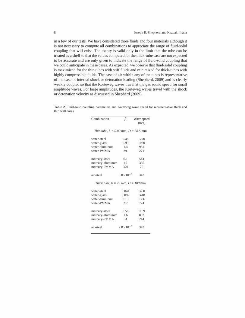
in a few of our tests. We have considered three fluids and four materials although itis not necessary to compute all combinations to appreciate the range of fluid-solidcoupling that will exist. The theory is valid only in the limit that the tube can betreated as a shell so that the values computed for the thick-tube case are not expectedto be accurate and are only given to indicate the range of fluid-solid coupling thatwe could anticipate in these cases. As expected, we observe that fluid-solid couplingis maximized for the thin tubes with stiff fluids and minimized for thick-tubes withhighly compressible fluids. The case of air within any of the tubes is representativeof the case of internal shock or detonation loading (Shepherd, 2009) and is clearlyweakly coupled so that the Korteweg waves travel at the gas sound speed for smallamplitude waves. For large amplitudes, the Korteweg waves travel with the shockor detonation velocity as discussed in Shepherd (2009).
Table 2 Fluid-solid coupling parameters and Korteweg wave speed for representative thick andthin wall cases.
Combination β Wave speed(m/s)
Thin tube, h = 0.89mm, D = 38.5mm
water-steel 0.48 1220water-glass 0.99 1050water-aluminum 1.4 961water-PMMA 29. 271
mercury-steel 6.1 544mercury-aluminum 17 335mercury-PMMA 370 75
air-steel 3.0×10⁻⁵ 343
Thick tube, h = 25mm, D = 100 mm
water-steel 0.044 1450water-glass 0.092 1418water-aluminum 0.13 1396water-PMMA 2.7 774
mercury-steel 0.56 1159mercury-aluminum 1.6 893mercury-PMMA 34 244
air-steel 2.8×10⁻⁶ 343

Shock Loading and Failure of Fluid-Filled Tubular Structures 9
3 Limiting Cases of FSI
There are some obvious limiting cases that lead to simplifications when there areextreme values of the coupling parameterβ which can be rewritten as
β =ρ f a2
f
ρsa2s×
2Rh
=K f
E×
2Rh
.
3.1 Thick, stiff tubeβ ≪ 1
If the tube wall is sufficiently thick and/or stiff,
ρsa2sh≫ 2Rρ f a
2f ,
then motion of the tube wall does not influence the wave propagation speed whichis just the value of the sound speedaf in the fluid for weak waves or the wave front(shock or detonation) speed U for large amplitude waves.
Wave speed forβ ≪ 1:Weak waves,
c≈ af .
Shock or detonation waves,c= U .
In this regime, the motion of the fluid can be computed as though the tube is rigidand the motion of the tube estimated by applying the computedpressures within thefluid as boundary conditions to the solid. This is the situation of a shock wave in airor gaseous detonation inside a metal tube, see the discussions in Beltman and Shep-herd (2002), Beltman et al. (1999). As long as the tube thickness to diameter ratioexceeds 10−2, i.e., wall thickness is at least 1% of the diameter, then theparameterβ ≤ 10−2. This is satisfied for all commercial pipe and tubing components. It ispossible to consider the tube to be rigid for the purposes of computing the shock ordetonation wave motion allowing very simplified (one-dimensional) models of thepressure waves in the gas to be employed (Beltman and Shepherd, 2002, Beltmanet al., 1999). In these cases, the deformations of the tube are usually confined tothe elastic regime and the failure mode is due to cracks initiating at flaws in thetube wall, see Chao and Shepherd (2005a, 2004). It is also possible to obtain plas-tic deformation for extremely thin-walled, low-strength tubes and high detonationpressures (Shepherd, 2009). Fluid-structure coupling could be significant for thesecases and this is a subject of active investigation in our laboratory.
10 Joseph E. Shepherd and Kazuaki Inaba
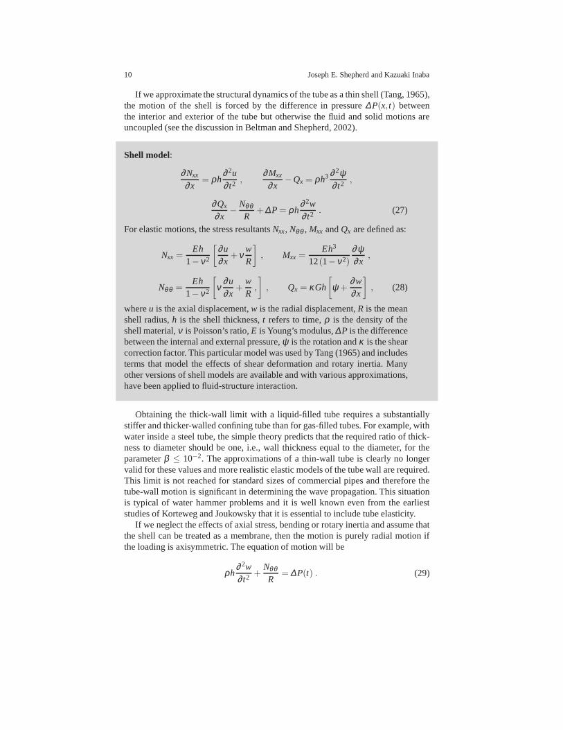
If we approximate the structural dynamics of the tube as a thin shell (Tang, 1965),the motion of the shell is forced by the difference in pressure ∆P(x, t) betweenthe interior and exterior of the tube but otherwise the fluid and solid motions areuncoupled (see the discussion in Beltman and Shepherd, 2002).
Shell model:
∂Nxx
∂x= ρh
∂ 2u∂ t2 ,
∂Mxx
∂x−Qx = ρh3 ∂ 2ψ
∂ t2 ,
∂Qx
∂x−
NθθR
+∆P= ρh∂ 2w∂ t2 . (27)
For elastic motions, the stress resultantsNxx, Nθθ , Mxx andQx are defined as:
Nxx =Eh
1−ν2
[∂u∂x
+νwR
]
, Mxx =Eh3
12(1−ν2)
∂ψ∂x
,
Nθθ =Eh
1−ν2
[
ν∂u∂x
+wR,
]
, Qx = κGh
[
ψ +∂w∂x
]
, (28)
whereu is the axial displacement,w is the radial displacement,R is the meanshell radius,h is the shell thickness,t refers to time,ρ is the density of theshell material,ν is Poisson’s ratio,E is Young’s modulus,∆P is the differencebetween the internal and external pressure,ψ is the rotation andκ is the shearcorrection factor. This particular model was used by Tang (1965) and includesterms that model the effects of shear deformation and rotaryinertia. Manyother versions of shell models are available and with various approximations,have been applied to fluid-structure interaction.
Obtaining the thick-wall limit with a liquid-filled tube requires a substantiallystiffer and thicker-walled confining tube than for gas-filled tubes. For example, withwater inside a steel tube, the simple theory predicts that the required ratio of thick-ness to diameter should be one, i.e., wall thickness equal tothe diameter, for theparameterβ ≤ 10−2. The approximations of a thin-wall tube is clearly no longervalid for these values and more realistic elastic models of the tube wall are required.This limit is not reached for standard sizes of commercial pipes and therefore thetube-wall motion is significant in determining the wave propagation. This situationis typical of water hammer problems and it is well known even from the earlieststudies of Korteweg and Joukowsky that it is essential to include tube elasticity.
If we neglect the effects of axial stress, bending or rotary inertia and assume thatthe shell can be treated as a membrane, then the motion is purely radial motion ifthe loading is axisymmetric. The equation of motion will be
ρh∂ 2w∂ t2 +
NθθR
= ∆P(t) . (29)

Shock Loading and Failure of Fluid-Filled Tubular Structures 11
For elastic motions, the stress resultant is
Nθθ =Eh
1−ν2
wR, (30)
and the equation of motion is that of a forced simple harmonicoscillator, which isreferred to as a single-degree-of-freedom model in the structural response commu-nity. The natural frequency of oscillation is given by the fundamental mode of radialor “hoop” motion.
Single degree of freedom model:
∂ 2w∂ t2 +ω2
hw=∆P(t)
ρh. (31)
Natural frequency:
ωh =1R
√
Eρ(1−ν2)
, fh =ωh
2π. (32)
The single degree of freedom model is quite limited since theneglect of bendingstresses effectively makes each shell element independent. Including bending whilestill neglecting transverse shear and rotary inertia leadsto the following model equa-tion (Bhuta, 1963, Simkins, 1995), which is equivalent to that of an Euler-Bernoullibeam on an elastic foundation with a traveling load, a model that has been exten-sively studied in many different contexts such as the loading created by the motionof trains or rocket sleds (Kenney, 1954).
Simplified flexural wave model:
Eh2
12ρ(1−ν2)
∂ 4w∂x4 +
∂ 2w∂ t2 +ω2
ow=∆P(x, t)
ρh, (33)
where the frequencyωo is
ωo =1R
√
Eρ. (34)
Steady traveling wave solutions on a long tube (Bhuta, 1963,Simkins, 1995)show a resonance when the traveling load moves at a critical propagationspeed
Vc =
√
Eh
ρR√
3(1−ν2). (35)

12 Joseph E. Shepherd and Kazuaki Inaba
This resonance has been observed in diverse traveling load situations such asgun tubes (Simkins et al., 1993), shock waves (Beltman et al., 1999), and detona-tion waves (Beltman and Shepherd, 2002). Although quite simplified, the essentialfeatures of dispersive waves and a critical speed are captured by this model.
3.2 Coupled fluid motion and tube deformation,β = O(1)
In the coupled situation, the fluid motion must be simultaneously considered withthe motion of the tube. The motions are coupled together at the boundary betweenthe tube material (solid) and the fluid inside the tube. For realistic fluids, this meansthat the fluid sticks to the boundary, and as long as the tube isintact, does not pen-etrate the boundary.1 In addition, the tangential (shear) and normal stresses at theboundary must be continuous so that the traction forces on the boundary of the solidare equal to the surface forces obtained by evaluating the fluid stress tensor at thatlocation. A common simplification is to treat the fluid as inviscid and allow slipalong the tube interior surface with vanishing shear stressin the fluid. For simpleboundary shapes and small amplitude motion, the coupling can be implemented an-alytically by linearizing the location of the boundary. Forcomplex boundary shapesand large amplitude motions, numerical methods (see the discussion in Arienti et al.,2003) are needed to define the boundary location and couple the fluid and solid sim-ulations.
A special case of coupled motion is small amplitude or acoustic waves in thefluid and elastic vibrations of the solid. This situation hasbeen extensively con-sidered in the context of underwater sound (Junger and Feit,1986), aeroelasticityand aerodynamically generated sound (Howe, 1998). In a stationary, homogeneous,ideal (inviscid) fluid, the flow can be derived from a velocitypotentialφ that sat-isfies the wave equation. For axisymmetric situations, the flow is two dimensional(x, r) and there are only two velocity components(u,v).
Fluid acoustics:
1 A complication that is observed in the present tests is cavitation (Trevena, 1987), the generationof cavities or bubbles when tension (negative pressure) occurs due to wave interactions in a liquid-filled tube. This can result in the separation of tube interior wall from the liquid as well as interiorcavities. Although of great importance in water hammer (Wylie and Streeter, 1993, Watters, 1984)and underwater explosions (Kedrinsky, 2005), we have omitted discussion of that aspect of FSIfrom this review.
Shock Loading and Failure of Fluid-Filled Tubular Structures 13
P′ = P−Po =−ρo∂φ∂ t
, (36)
ρ ′ = ρ −ρo = P′/a2o , (37)
u = (u,v) , (38)
= ∇φ , (39)
∇2φ −1a2
o
∂ 2φ∂ t2 = 0 . (40)
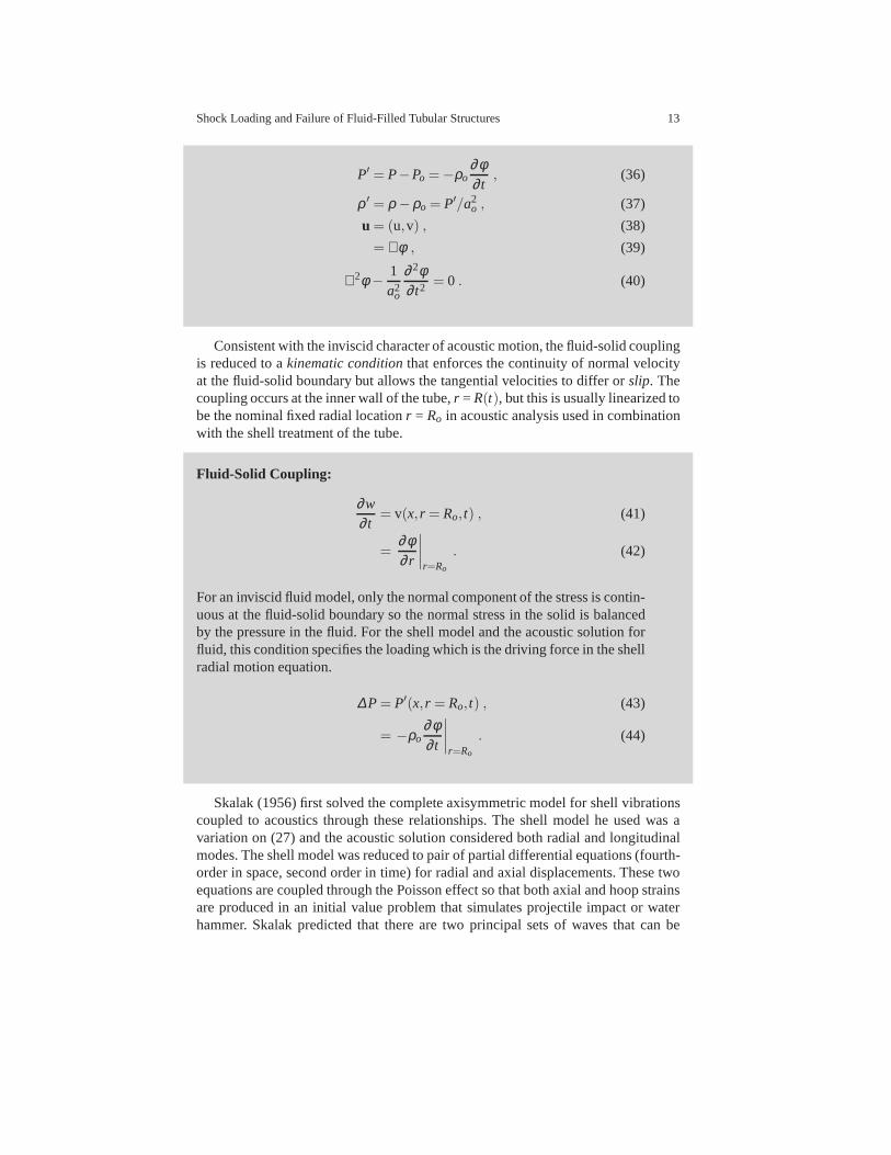
Consistent with the inviscid character of acoustic motion,the fluid-solid couplingis reduced to akinematic conditionthat enforces the continuity of normal velocityat the fluid-solid boundary but allows the tangential velocities to differ orslip. Thecoupling occurs at the inner wall of the tube,r = R(t), but this is usually linearized tobe the nominal fixed radial locationr = Ro in acoustic analysis used in combinationwith the shell treatment of the tube.
Fluid-Solid Coupling:
∂w∂ t
= v(x, r = Ro, t) , (41)
=∂φ∂ r
∣∣∣∣r=Ro
. (42)
For an inviscid fluid model, only the normal component of the stress is contin-uous at the fluid-solid boundary so the normal stress in the solid is balancedby the pressure in the fluid. For the shell model and the acoustic solution forfluid, this condition specifies the loading which is the driving force in the shellradial motion equation.
∆P= P′(x, r = Ro, t) , (43)
= −ρo∂φ∂ t
∣∣∣∣r=Ro
. (44)
Skalak (1956) first solved the complete axisymmetric model for shell vibrationscoupled to acoustics through these relationships. The shell model he used was avariation on (27) and the acoustic solution considered bothradial and longitudinalmodes. The shell model was reduced to pair of partial differential equations (fourth-order in space, second order in time) for radial and axial displacements. These twoequations are coupled through the Poisson effect so that both axial and hoop strainsare produced in an initial value problem that simulates projectile impact or waterhammer. Skalak predicted that there are two principal sets of waves that can be

14 Joseph E. Shepherd and Kazuaki Inaba
observed. A weak axial strain wave precursor moving at the bar speed runs aheadof the main pressure and hoop strain disturbances, which aremoving at close tothe Korteweg speed. Skalak gives an approximate analytic solution to an initial-value problem similar to projectile impact but the expressions are quite complexand almost all subsequent research on water hammer has used either the simplifiedversion of his model (discussed subsequently) or numericalsimulations of the fullequations.
3.2.1 Simplified FSI models
In his 1956 paper, Skalak introduced a simpler model that is more realistic than theKorteweg model but less complex than the full coupled 2-D shell-acoustic model.This “four-equation” model has been successfully applied (Tijsseling, 1996, 2003,2007) to a number of water hammer problems, demonstrating reasonable agreementwith measured pressures and strains. The model is a straightforward extension of theKorteweg model to include axial wave propagation and Poisson coupling betweenradial and axial deformation. The fluid modeling assumptions are identical to theKorteweg model, neglecting bending stresses, shear effects, rotary and radial inertia.The fluid equations are identical to (8) and (9) and the acoustic approximation isused to relate pressure and density changes in the fluid. The area change is computedin terms of the change in tube radius, which is equivalent to the coupling relationship(41),
1A
dAdt
=2R
∂w∂ t
. (45)
The governing equation set reduces to two equations for the axial fluid motion, onewave equation for axial tube motion and the static force balance for the radial motionof the tube. The variables are only a function of axial distancex and timet for thesimplified model, and the equations are hyperbolic, enabling solutions by standardwave propagation techniques such as the method of characteristics (Wiggert et al.,1987, Li et al., 2003) or Godunov (Gale and Tiselj, 2008) methods.
The “Four-Equation” Model :
1
a2f
∂P′
∂ t+ρo
∂u∂x
+ρo2R
∂w∂ t
= 0 , (46)
ρo∂u∂ t
=−∂P′
∂x, (47)
∂Nxx
∂x= ρh
∂ 2u∂ t2 , (48)
NθθR
= P′ . (49)

Shock Loading and Failure of Fluid-Filled Tubular Structures 15
Skalak explored the consequences of this model and showed that the equationset admits steady traveling waves with two eigen-speedsc1 and c2 that coincidewith the principal speeds of the full model. The higher speedc2 is approximatelythe speed of axial waves in the tube wall
√
E/ρs(1−ν2) and the lower speedc1 isapproximately the Korteweg wave speed given by (21). In addition, the amplitudeof the deformations and fluid velocities (relative to the fluid pressure) are the samein the reduced and full models. In particular, the peak pressure and fluid velocity ina steadily traveling wave of speedc are related by
P′ = ρcu′ , (50)
which is an extension of usual acoustic relation for fluidsP′ = ρaf u′.One key difference is that the full model is dispersive and sharp wave fronts will
spread out with time (Tijsseling et al., 2008) whereas in thereduced model, thefronts remain sharp. The main physical effect responsible for dispersion is radialinertia with bending stiffness playing a secondary role.
3.3 Thin, flexible tubeβ ≫ 1
If the tube wall is sufficiently flexible then the compressibility of the fluid is negli-gible compared to the effective compressibility due to the extension of the tube. Inthis limit, the propagation speed is determined solely by the inertia of the fluid andthe elastic properties of the tube,
c≈
√
Ao
ρ f
∂P′
∂A, (51)
which can be simplified using the relationship (15)
c≈
√
Eρ f
h2R
. (52)
In the field of arterial wave mechanics (Parker, 2009), relationship (52) is gener-ally known as the Moen-Korteweg equation. For thin tubes, this speed is quite a bitlower than the bar speed (22) or thin-tube axial wave speed since
c≈ ab
√
ρs
ρ f
h2R
. (53)
This is the limit often considered in connection with flow in blood vessels and peri-staltic pumping in the intestinal tract (Grotberg and Jensen, 2004). This propagation

16 Joseph E. Shepherd and Kazuaki Inaba
of extension waves in the arteries is responsible for the phenomenon of “pulse”that is used to sense the frequency of the heart beat. The pressure pulse generatedby the pumping of blood into the aorta from the heart creates apropagating wavethat moves with a speed on the order of 3-6 m/s near the heart and further away,as the arteries become smaller, the speed increases up to 15-35 m/s. In the case ofthe venous system, the effect of external pressure can lead to the phenomenon of“collapse” which will restrict the flow of blood. The collapse of a flexible, fluid-filled tube is a type of buckling instability and leads to a highly non-circular tubecross-section and a nonlinear relationship between pressure and area.
Beam (1968) carried out a novel analysis of the incompressible fluid limit using aLagrangian formulation of the dynamics and considering large amplitude deforma-tion of the tube wall. Treating the motion as fully nonlinear, Beam was able to deter-mine conditions under which compression waves would steepen to form shock-likedisturbances in the pressure pulses within the arteries. Heformulated the hypothesisthat these shock waves were the origin of the high-frequencyKorotkoff sounds thatare the basis of indirect blood pressure measurement (sphygmomanometer) using apressurized cuff and a stethoscope.
4 Experimental Results
Impulsively excited wave propagation in fluid-filled tubes has been studied for shockand detonation waves inside metal tubes filled with gas or water. These studies haveexamined both the elastic and plastic deformation in the tubes. We have selectedseveral examples to illustrate the cases of smallβ ≪ 1, moderateβ ∼ 1, and largeβ ≫ 1, fluid-solid coupling. .
4.1 Small coupling
This is the case of a detonation or shock wave in a gas within a thin-wall metal tube.The value ofβ is small (less than 10−3) and there is minimal fluid-solid couplingin the sense discussed above. An ideal detonation wave propagates with a constantspeed, the Chapman-Jouguet (CJ) velocity and there is a rapid pressure increaseacross the wave followed by a decay to a constant value. An ideal shock wave load-ing would be in the form of a constant velocity wave followed by a constant pressure.The pressure behind the wave front is imposed in an axially-symmetric fashion onthe tube wall and excites oscillatory deflections in the tubewall. Due to the lackof coupling between fluid and solid motion, there is essentially no influence of thetube motion on detonation wave speed or flow behind the detonation. Therefore, theeffect of an internal shock or detonation wave on the tube is to provide a travelingor moving load applied at the interior tube surface in the radially outward direction.

Shock Loading and Failure of Fluid-Filled Tubular Structures 17
The problem of a traveling internal load on a tube has been extensively examined(see Beltman et al., 1999, Beltman and Shepherd, 2002) and inthe simplest formu-lation is equivalent to a traveling load imposed on a beam supported by an elasticfoundation. Considering the tube as a thin-shell, there arefour axisymmetric modesof tube motion (Tang, 1965) that are generated in this case. In order of increasingwave speed, these are the flexural waves, shear waves, bar waves, and longitudinalwaves. The flexural wave exhibits the largest amplitude of tube hoop strain and is themost significant of all of these modes. Flexural waves, like other structural modes,do not have a well-defined wave speed but are dispersive and the main wave frontmoves at a phase velocity that is equal to the speed of the loading front (shock ordetonation wave speed). For weak shock waves, this is the acoustic speed in the gasso that the flexural wave corresponds to theβ → 0 limit of the Korteweg wave modeof acoustic disturbances. For strong shock waves or detonations, the wave speed ingas may significantly exceed the gas acoustic speed and this may excite very strongdeflections in the tube for certain speed ranges. In particular, there is a pronouncedresonance (Beltman et al., 1999, Beltman and Shepherd, 2002, Chao and Shepherd,2005b) when the phase speed is equal to the group velocity andlarge amplitudehoop strain oscillations can be observed in this situation.
For a given pressure behind the gas wave, the maximum hoop strain is a func-tion of the wave speed relative to the critical speed or groupvelocity of the flexuralwaves. Chao and Shepherd (2005b) examined the possibility of additional resonanceat the modified shear wave speed in the shell but did not observe any amplifica-tions of hoop strains in this speed range in agreement with the Tang model andfinite element simulations. Amplification of the shear strains is predicted (Chao andShepherd, 2005b) but the effect is modest in comparison withthe flexural wave res-onance. Additional resonances at even higher speeds, in therange between the bulksound speed and dilatation speed, are observed in finite element numerical simula-tions by Lewis and Nechitailo (2007). It will be difficult to experimentally observethese effects in gases with metal tubes but it may be possiblein plastic tubes withthe additional complication of viscoelastic behavior.
4.2 Elastic motions
Fig. 2a shows gaseous detonation pressure histories measured at intervals of 127mm along the axis of a steel tube 1.25 m long and 127 mm inside diameter witha 12.7 mm thick wall, (see Liang et al., 2006a, for details). Fig.2b shows the hoopstrain histories at the corresponding axial locations. Comparing the two plots, wecan see that the main flexural wave front moves at the speed of the detonation front,about 2090 m/s. A small amplitude precursor can be observed moving ahead of themain wave front, the leading edge of the precursor travels atabout 5000 m/s, closeto the bar wave speed in the tube. The hoop strain oscillations have a frequency offh = 17.5 kHz, which corresponds to the hoop or breathing mode associated with apurely radial motion. The amplitude modulation of the hoop oscillations is mainly

18 Joseph E. Shepherd and Kazuaki Inaba
to the superposition of oscillations created by the incident detonation and reflectedshock wave with additional disturbances created by the welded-on pressure gageports. The tube is stiff and the peak pressures are relatively modest so that the peakstrains are less than 250µstrain (ε ≤ .00025) and all motion is purely in the elasticregime. A more ideal response can be obtained by carrying outtests with a section
0
10
20
30
40
50
60
70
80
90
-0.5 0 0.5 1 1.5 2
Pre
ssu
re (
MP
a)
time (ms)
shot 57
P1
P2
P3
P4
P5
P6
P7
P8
0
500
1000
1500
2000
2500
-0.5 0 0.5 1 1.5 2
Sta
in (
mic
ro s
train
)
time (ms)
shot 57
S1
S2
S3
S4
S5
S6
S7
S8
(a) (b)
Fig. 2 Elastic structural response of a steel tube to a gaseous detonation. a) pressure histories. b)strain histories (bonded strain gages) (Liang et al., 2006a).
of tube with a uniform cross-section and carefully-controlled boundary conditions(Shepherd et al., 2008, Liang et al., 2006b). Nearly sinusoidal oscillations in radialdeflection with constant amplitude can be observed in Fig. 3.The specimen tubeis 6061T6 aluminum, the same type used as in previous studies. Outer diameter is41.28 mm (1.625 in). The thickness of the tube is nominally 0.89 mm (0.035 in) butactual dimensions vary by +/- 10% due to the manufacturing technique. The tubewas held by collets spaced 420 mm apart and the measuring location was halfwaybetween the collets.
4.3 Plastic motions
If the tube wall is sufficiently thin and the shock or detonation pressure sufficientlyhigh, plastic deformation of the tube will occur (Smith, 1986, 1990). When thishappens, the radial deflection of the tube is dominated by theresulting permanentdeformation and the oscillations that are so prominent in the elastic case are negligi-ble compared to the plastic deformation. Fig. 4 shows a set ofhoop strain historiesmeasurements for the same internal dimensions as shown previous, 1.24 m long tubeand 127 mm inner diameter, but with a wall thickness of 1.5 mm.The detonationwave occurred in a stoichiometric methane-oxygen mixture at an initial pressure of0.35 MPa (Pintgen and Shepherd, 2006).
Because of these differences, the peak strains in this case are almost 100 timeslarger than in the elastic case shown previously. The steel is a mild carbon steel

Shock Loading and Failure of Fluid-Filled Tubular Structures 19
-500
0
500
1000
1500
2000
2500
0.8 0.85 0.9 0.95 1 1.05 1.1 1.15 1.2 1.25
hoop
str
ain
(mic
ro s
trai
n)
time (ms)
shot 21, loc 1, vib
Fig. 3 Elastic structural response of a thin-wall aluminum tube toa gaseous detonation as mea-sured by a optical displacement interferometer (Shepherd et al., 2008).
(C1010) which exhibits significant work hardening and strain rate effects that mustbe considered in order to predict the extent of the deformation. Very rapid changesin deformation are created by both the incident detonation and reflected shock wave.The reflected shock decays rapidly as it moves away from the reflecting end so thattwo distinct waves are particularly visible for the gage at 1.13 m. The rate of changeof the tube radius is limited primarily by inertia and on the time scale shown, therise time is relatively short so that the waves appear nearlyas a step change (“plasticshock wave”). If there is sufficient deformation to reach thetensile limit, ruptureand fragmentation can occur. Rupture due to gaseous detonation can occur underextreme loading conditions that are created by transition from deflagrations (flames)to the detonation mode of combustion (Shepherd, 2009). The related process ofcrack propagation from pre-existing flaws has been studied for detonation loadingin a series of experiments by Chao (2004).
4.4 High Explosives
There has also been a substantial amount of research, for example, by Duffey andMitchell (1973), Benham and Duffey (1974), Hodge (1956), Duffey (1971), Duf-fey and Krieg (1969), Fanous and Greiman (1988) and others cited in the reviewby Florek and Benaroya (2005), on the plastic response of tubes to high explosives.This is of great practical interest for confining explosions(Rodriguez and Duffey,2004, Duffey et al., 2002) for purposes of testing or transporting explosive materi-als. However, these situations typically involve concentrated energy releases and donot result in propagating deformation waves. A single bulgein the tube is typically

20 Joseph E. Shepherd and Kazuaki Inaba
-0.5
0
0.5
1
1.5
2
2.5
3
3.5
-1 -0.5 0 0.5 1 1.5
Str
ain
(%
)
time (ms)
S1 0.939m
S2 1.002m
S3 1.066m
S4 1.130m
S5 1.193m
Fig. 4 Plastic structural response (hoop strain) of a thin-wall steel tube to a gaseous detonation asmeasured by bonded strain gages. The short data lines at the left side of the figure indicate the finalresidual plastic deformation (Pintgen and Shepherd, 2006).
created by the explosion unless the energy release is sufficient to fracture the tube.For high explosives in air-filled tubes, it is possible to predict the final deforma-tion using approximate equations of motion when strain rateand strain hardeningeffects are taken into account. Similar experiments in water-filled tubes (Sanduskyet al., 1999, Chambers et al., 2001) have been carried out to provide data on wallmotion and internal pressure that can be used to validate simulations of underwaterexplosions (Wardlaw and Luton, 2000). Plastic deformations as large as 20% wererecorded in the middle portion of a 100 mm diameter aluminum (type 5086) tubewith a 5.35 mm wall thickness.
5 Moderate coupling
Experiments have been carried out at CIT (Inaba and Shepherd, 2008a,b) to createimpact-generated stress waves in a water-filled tube using the configuration shownin Fig. 1. A 700 g steel projectile was accelerated by compressed air through a 1.5m long barrel and impacted a polycarbonate buffer at the top of the tube. The pro-jectile velocity and impact dynamics were recorded with high-speed photography.The buffer accelerates impulsively as soon as it is impactedby the steel projectile,decelerates to a stop in about 1 ms and reverses direction. The buffer is sealed tothe tube with two o-rings to prevent the water from squirtingthrough the small gapbetween the buffer and tube.
A sharp pressure pulse (Fig. 5) is created by the initial impulse due to the impactof the projectile followed by an approximately exponentialdecay in time of pressuredue to the expansion waves generated as the projectile slowsdown. An elementary

Shock Loading and Failure of Fluid-Filled Tubular Structures 21
theory of the pressure pulse generation mechanism is given in the Appendix. Theincident pressure wave propagates down the tube with the Korteweg wave speed,reflects from the bottom closure of the tube with an increase in amplitude, thenpropagates back up to the buffer. When the compression wave reflects from the freesurface of the buffer, a tension wave is generated that propagates into the waterresulting in cavitation.
ProjectileBarrel
Polycarbonate
buffer
0.1 m
Test
specimen
Strain
gauges
Pressure
transducer
0.91 m
0.15 m
g1
g2
g3
g4
g5
g7
g6
0
20
40
60
80
100
120
140
160
0 0.5 1 1.5 2 2.5
pre
ssu
re (
MP
a)
time (ms)
12.5 mm steel shot62re!ectedincident
cavitation
Fig. 5 Pressure waves generated by projectile impact on a water-filled steel tube with a 12.5 mmthick wall (Inaba and Shepherd, 2008a).
5.1 Elastic Waves
For sufficiently low projectile velocities and/or sufficiently thick tubes, the structuraldeflections are elastic. Operating in this regime and using commercial metal tubes,we can test the conventional models based on water-hammer theory. The pressurewaves in the fluid are accompanied by longitudinal (axial) and hoop strain wavesin the tube wall. To observe these waves, Inaba and Shepherd (2008a) used thin-wall mild steel tubes (1020 type, 0.91 m long, 40 mm in diameter, 0.77 mm wallthickness) instrumented with bonded strain gages at 10 cm intervals (Fig. 6). Inagreement with the theory of Skalak (1956), the bulk of strain (primary wave) is inthe hoop direction and traveling at the Korteweg speed in phase with the pressurepulse. A small-amplitude longitudinal tension wave (precursor wave) propagates atthe thin-plate velocity
cp =
√
Eρs(1−ν2)
, (54)
22 Joseph E. Shepherd and Kazuaki Inaba
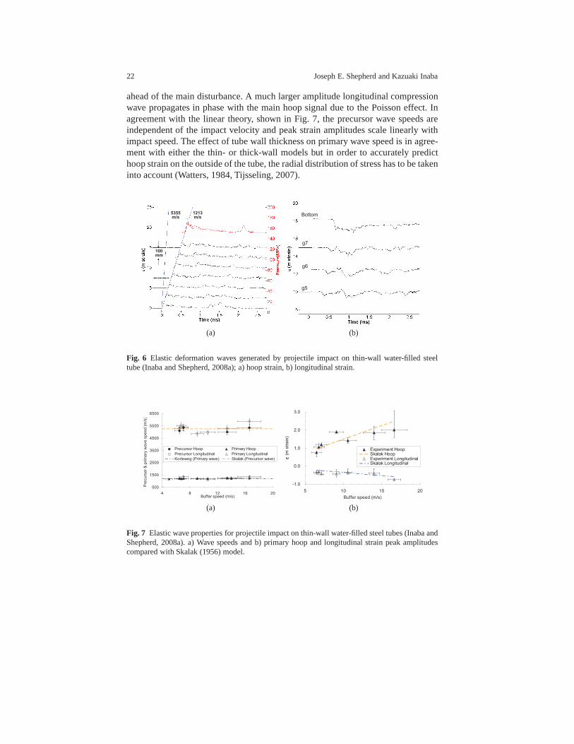
ahead of the main disturbance. A much larger amplitude longitudinal compressionwave propagates in phase with the main hoop signal due to the Poisson effect. Inagreement with the linear theory, shown in Fig. 7, the precursor wave speeds areindependent of the impact velocity and peak strain amplitudes scale linearly withimpact speed. The effect of tube wall thickness on primary wave speed is in agree-ment with either the thin- or thick-wall models but in order to accurately predicthoop strain on the outside of the tube, the radial distribution of stress has to be takeninto account (Watters, 1984, Tijsseling, 2007).
100
mm
1213
m/s
5355
m/sBottom
g7
g6
g5
(a) (b)
Fig. 6 Elastic deformation waves generated by projectile impact on thin-wall water-filled steeltube (Inaba and Shepherd, 2008a); a) hoop strain, b) longitudinal strain.
500
1500
2500
3500
4500
5500
6500
4 8 12 16 20Buffer speed (m/s)
Pre
cu
rse
r &
prim
ary
wa
ve
sp
ee
d (
m/s
)
Precursor Hoop Primary Hoop
Precursor Longitudinal Primary Longitudinal
Korteweg (Primary wave) Skalak (Precursor wave)
-1.0
0.0
1.0
2.0
3.0
5 10 15 20
Buffer speed (m/s)
ε (
m s
tra
in)
Experiment HoopSkalak HoopExperiment LongitudinalSkalak Longitudinal
(a) (b)
Fig. 7 Elastic wave properties for projectile impact on thin-wallwater-filled steel tubes (Inaba andShepherd, 2008a). a) Wave speeds and b) primary hoop and longitudinal strain peak amplitudescompared with Skalak (1956) model.
Shock Loading and Failure of Fluid-Filled Tubular Structures 23
800
900
1000
1100
1200
1300
1400
1500
0 4 8 12Tube wall thickness (mm)
Prim
ary
wa
ve
sp
ee
d (
m/s
)
Experiment (Primary hoop)
Korteweg (Thin-wall theory)
Tijsseling (Thick-wall theory)
0.00
0.05
0.10
0.15
0.20
0.25
0.30
0 10 20 30 40
Pressure (MPa)
(
m s
tra
in)
Experiment (Primary hoop)
Skalak (Thin-wall theory)
Tijsseling (Thick-wall theory)
(a) (b)
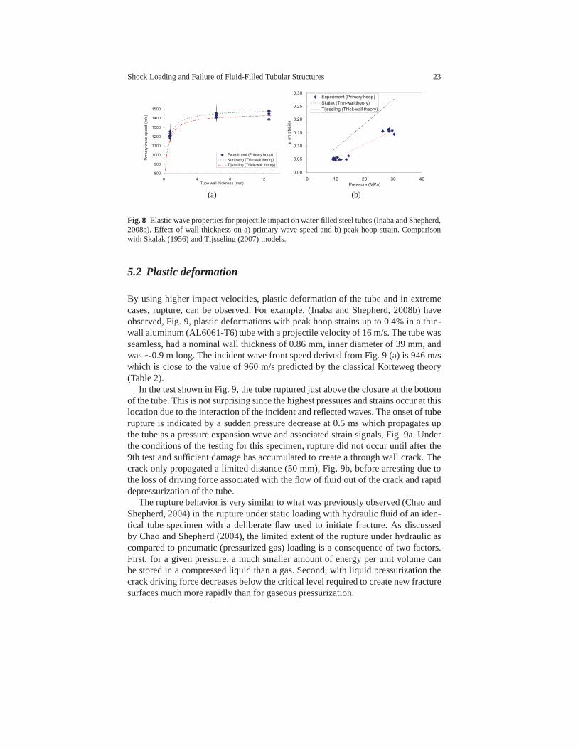
Fig. 8 Elastic wave properties for projectile impact on water-filled steel tubes (Inaba and Shepherd,2008a). Effect of wall thickness on a) primary wave speed andb) peak hoop strain. Comparisonwith Skalak (1956) and Tijsseling (2007) models.
5.2 Plastic deformation
By using higher impact velocities, plastic deformation of the tube and in extremecases, rupture, can be observed. For example, (Inaba and Shepherd, 2008b) haveobserved, Fig. 9, plastic deformations with peak hoop strains up to 0.4% in a thin-wall aluminum (AL6061-T6) tube with a projectile velocity of 16 m/s. The tube wasseamless, had a nominal wall thickness of 0.86 mm, inner diameter of 39 mm, andwas∼0.9 m long. The incident wave front speed derived from Fig. 9 (a) is 946 m/swhich is close to the value of 960 m/s predicted by the classical Korteweg theory(Table 2).
In the test shown in Fig. 9, the tube ruptured just above the closure at the bottomof the tube. This is not surprising since the highest pressures and strains occur at thislocation due to the interaction of the incident and reflectedwaves. The onset of tuberupture is indicated by a sudden pressure decrease at 0.5 ms which propagates upthe tube as a pressure expansion wave and associated strain signals, Fig. 9a. Underthe conditions of the testing for this specimen, rupture didnot occur until after the9th test and sufficient damage has accumulated to create a through wall crack. Thecrack only propagated a limited distance (50 mm), Fig. 9b, before arresting due tothe loss of driving force associated with the flow of fluid out of the crack and rapiddepressurization of the tube.
The rupture behavior is very similar to what was previously observed (Chao andShepherd, 2004) in the rupture under static loading with hydraulic fluid of an iden-tical tube specimen with a deliberate flaw used to initiate fracture. As discussedby Chao and Shepherd (2004), the limited extent of the rupture under hydraulic ascompared to pneumatic (pressurized gas) loading is a consequence of two factors.First, for a given pressure, a much smaller amount of energy per unit volume canbe stored in a compressed liquid than a gas. Second, with liquid pressurization thecrack driving force decreases below the critical level required to create new fracturesurfaces much more rapidly than for gaseous pressurization.

24 Joseph E. Shepherd and Kazuaki Inaba
-1 -0.5 0 0.5 1 1.5 2 2.5
0
5
10
15
20
25
Time (ms)
εε εε (m
str
ain
)
-1 -0.5 0 0.5 1 1.5 2 2.5
0
50
100
150
Pre
ssu
re (
MP
a)100 mm
946 m/s
(a) (b)
Fig. 9 Deformation in plastic regime and rupture generated by projectile impact on a water-filledaluminum tube (Inaba and Shepherd, 2008b). a) hoop strain and pressure histories and b) tuberupture at the tube bottom. Impact speed 15.8 m/s, 50 mm rupture length.
Strains can be observed that are greatly in excess of the nominal elastic propor-tional limit (ε = .002) in tests with more ductile tubes and higher projectile veloc-ities. Using a new vertical gas gun facility we constructed in our laboratory at theCalifornia Institute of Technology, we have carried out experiments with projectilespeeds up to 100 m/s. Hoop strain and pressure histories are shown in Fig. 10 fora 65 m/s impact on a water-filled 1.59 mm thickness, 40.0 mm inner diameter, 0.9m long mild steel tube. The precursor and primary wave velocities are 5219 and1346 m/s, respectively. Despite the very large (up to 16%) permanent deformationsthat occur in this test, the observed wave speeds are in reasonable agreement withthe Skalak (1956) model predictions of 5226 m/s and 1337 m/s.This good agree-ment is apparently a consequence of the limited deformationthat takes place in theprecursor and primary waves, making the elastic assumptionof the Skalak model areasonable approximation.
A relatively long time is required to reach the ultimate plastic deformation ascompared to the initial elastic deformation waves. The situation appears to be verysimilar to that of uniaxial stress waves in shock compression (see Ch. 3 of Meyers,1994): An elastic precursor wave with an amplitude given by the proportional limittravels at the elastic longitudinal wave speed in front of a lower speed plastic wavewith a continuous increase in strain (stress) up to the final level of permanent defor-mation. In the case of the water-filled tube, Fig. 10b, significant attenuation of theplastic wave is observed with increasing distance from the impact point. This occursin uniaxial shock compression testing due the attenuation of a following expansion

Shock Loading and Failure of Fluid-Filled Tubular Structures 25
wave. In the present case, we speculate that there are multiple factors including notonly the expansion wave but also the radial motion of the tubewall and the energyabsorption due to plastic work. Although the Korteweg theory can be naively ex-tended to plastic deformation, the dispersive nature of theplastic deformation wavessuggests that radial motion, fluid and tube inertia effects may also be significant inthe plastic case and the simplifying assumptions of the Korteweg theory may not bevalid in the case of large plastic deformation.
-0.5 0 0.5 1 1.5 2 2.5 3 3.50
10
20
30
40
50
60
70
80
90
100
Time (ms)
εε εε (m
str
ain
)
-0.5 0 0.5 1 1.5 2 2.5 3 3.50
20
40
60
80
100
120
140
160
180
200
Pre
ssu
re (
MP
a)
200 mm
5219 m/s
1346 m/s
(a)
(b)
Fig. 10 Large plastic deformation generated by projectile impact on a water-filled steel tube. a)hoop strain and pressure histories and b) bulge (16% maximumstrain) near the location of thebottom of the buffer. The initial buffer speed following impact was 62.7 m/s.
5.3 Composite and Polymer tubes
The strain waves observed in metal tubes are relatively straightforward to interpret,with distinct incident and reflected waves. The waves in composite and polymertubes are more complex. This is due to the anisotropic natureof the the roll-wrappedand filament wound composite tubes that we have used in our tests as well as theviscoelastic nature of the polymer tubes and matrix materials. Although many fea-
26 Joseph E. Shepherd and Kazuaki Inaba
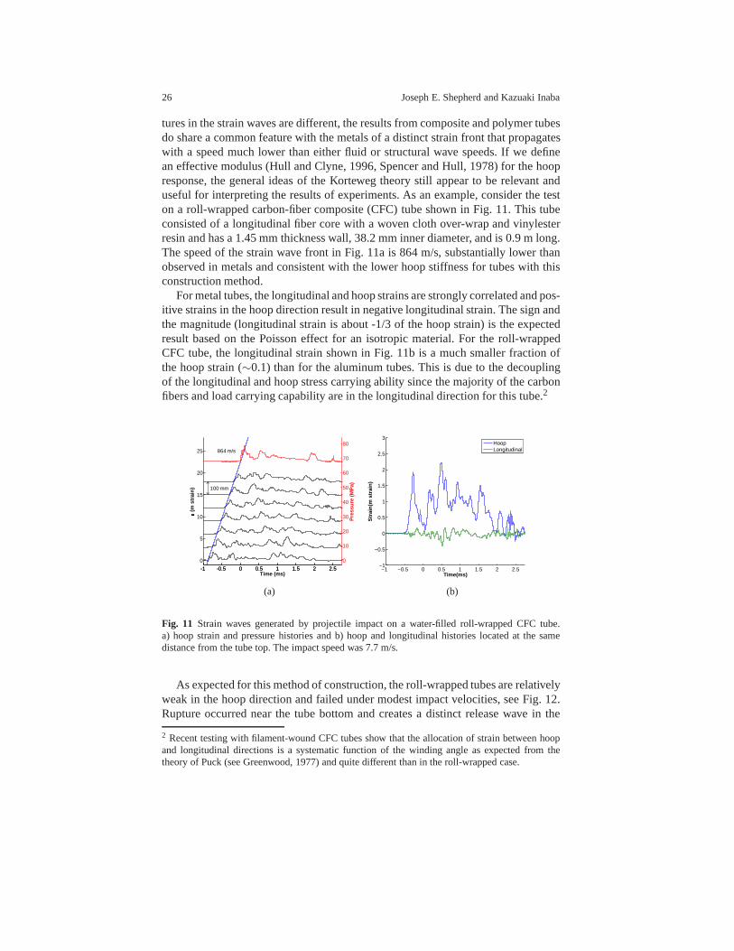
tures in the strain waves are different, the results from composite and polymer tubesdo share a common feature with the metals of a distinct strainfront that propagateswith a speed much lower than either fluid or structural wave speeds. If we definean effective modulus (Hull and Clyne, 1996, Spencer and Hull, 1978) for the hoopresponse, the general ideas of the Korteweg theory still appear to be relevant anduseful for interpreting the results of experiments. As an example, consider the teston a roll-wrapped carbon-fiber composite (CFC) tube shown inFig. 11. This tubeconsisted of a longitudinal fiber core with a woven cloth over-wrap and vinylesterresin and has a 1.45 mm thickness wall, 38.2 mm inner diameter, and is 0.9 m long.The speed of the strain wave front in Fig. 11a is 864 m/s, substantially lower thanobserved in metals and consistent with the lower hoop stiffness for tubes with thisconstruction method.
For metal tubes, the longitudinal and hoop strains are strongly correlated and pos-itive strains in the hoop direction result in negative longitudinal strain. The sign andthe magnitude (longitudinal strain is about -1/3 of the hoopstrain) is the expectedresult based on the Poisson effect for an isotropic material. For the roll-wrappedCFC tube, the longitudinal strain shown in Fig. 11b is a much smaller fraction ofthe hoop strain (∼0.1) than for the aluminum tubes. This is due to the decouplingof the longitudinal and hoop stress carrying ability since the majority of the carbonfibers and load carrying capability are in the longitudinal direction for this tube.2
-1 -0.5 0 0.5 1 1.5 2 2.5
0
5
10
15
20
25
Time (ms)
εε εε (m
str
ain
)
-1 -0.5 0 0.5 1 1.5 2 2.5
0
10
20
30
40
50
60
70
80
Pre
ssu
re (
MP
a)
100 mm
864 m/s
−1 −0.5 0 0.5 1 1.5 2 2.5−1
−0.5
0
0.5
1
1.5
2
2.5
3
Time(ms)
Str
ain
(m s
trai
n)
HoopLongitudinal
(a) (b)
Fig. 11 Strain waves generated by projectile impact on a water-filled roll-wrapped CFC tube.a) hoop strain and pressure histories and b) hoop and longitudinal histories located at the samedistance from the tube top. The impact speed was 7.7 m/s.
As expected for this method of construction, the roll-wrapped tubes are relativelyweak in the hoop direction and failed under modest impact velocities, see Fig. 12.Rupture occurred near the tube bottom and creates a distinctrelease wave in the
2 Recent testing with filament-wound CFC tubes show that the allocation of strain between hoopand longitudinal directions is a systematic function of thewinding angle as expected from thetheory of Puck (see Greenwood, 1977) and quite different than in the roll-wrapped case.

Shock Loading and Failure of Fluid-Filled Tubular Structures 27
strain histories (Fig. 12). The rupture event is much more dramatic than in aluminumsince the failure in CFC is by a high-speed brittle fracture rather than the quickly-arresting ductile rupture that is observed in the aluminum tubes. Rupture of the CFCtube occurred on the first high impact speed test while the ductility of the aluminumtube delayed rupture until the damage had accumulated from anumber of successiveimpacts.
The roll-wrapped CFC tube rupture was in the form of a long, straight crack par-allel to the tube axis and serendipitously intersected the longitudinal strain gagesso that the strain signals can be used to deduce the apparent crack tip speed to beabout 2000 m/s, These are much higher than typical crack tip speeds of 200-300m/s observed (Chao and Shepherd, 2004, 2005a) in detonation-driven fracture ofaluminum. However, this value is actually quite a bit lower than crack tip velocitiesof up to 7000 m/s that were observed by Coker and Rosakis (2001) in impact experi-ments on mode I and II cracks in unidirectional graphite-epoxy composite plates. Asdiscussed in Chao and Shepherd (2004), the cracks in internally-pressurized tubesinitiate in Mode I since the major principal stress is in the hoop direction, perpen-dicular to the initial crack tip motion. However, in thin ductile tubes, the plasticdeformation of the material adjacent to the crack quickly results in a transition tomixed mode fracture (Chao and Shepherd, 2005a).
-1 -0.5 0 0.5 1 1.5 2 2.50
5
10
15
20
25
30
35
40
45
Time (ms)
εε εε (m
str
ain
)
-1 -0.5 0 0.5 1 1.5 2 2.50
20
40
60
80
100
120
Pre
ssu
re (
MP
a)100 mm
933 m/s
Fig. 12 Hoop strain and pressure histories generated by projectileimpact on a water-filled roll-wrapped CFC tube. This tube failed by fracture near the bottom just after reflection of the pressurewave.

28 Joseph E. Shepherd and Kazuaki Inaba
The roll-wrapped CFC tubes always burst near the bottom boundary3 in the testswith higher driver pressures while a filament-wound glass-reinforced plastic (GRP)tube survived intact under these same conditions. The GRP tube has a 1.60 mmthickness, 38.8 mm inner diameter, 0.9 m long with a winding angle of 40 degrees.The hoop strain histories shown in Fig. 13 for the GRP tubes are similar to thoseof the CFC tubes. Longitudinal strain histories shown in Fig. 13b for the GRP tubeare correlated to hoop strains similar to those in the Al tubes, in contrast to theCFC tubes. The primary wave velocity measured for the hoop strain wave front is904 m/s, similar to the speeds in the roll-wrapped CFC tubes.In Fig. 13b, peak hoopstrains greater than 0.7% were observed but residual strainnear the reflecting bound-ary is still negligible after the experiment. The primary flexural wave velocities are949 m/s, slightly faster than those in Fig. 13a.
-1 0 1 2 3-2
0
2
4
6
8
10
12
14
16
18
Time (ms)
εε εε (m
str
ain
)
-1 0 1 2 3
0
5
10
15
20
25
30
35
Pre
ssu
re (
MP
a)
100 mm
904 m/s
-1 0 1 2 3-5
0
5
10
15
20
25
30
35
40
45
50
Time (ms)
εε εε (m
str
ain
)
-1 0 1 2 3-10
0
10
20
30
40
50
60
70
80
90
100
Pre
ssu
re (
MP
a)
100 mm
949 m/s
(a) (b)
Fig. 13 Hoop and pressure histories generated by projectile impacton a water-filled GRP tube. a)impact speed 6.8 m/s and b) impact speed 18.8 m/s.
The polycarbonate tube (PC) is more flexible and exhibits more significant fluid-solid coupling than either metal or composite tubes. The PC tube we tested is atransparent tube with a 6.4 mm thick-wall and a 38 mm inner diameter. Limitedresults are available since the primary purpose of these tests were to visualize cavi-tation. The primary wave propagates at 552 m/s, Fig. 14, muchslower than wavesin metal or composite tubes. The bar sound speed of the PC tubeis estimated to be1386 m/s using a density of 1250 kg/m3 and Young’s modulus 2.4 GPa. The cou-pling parameterβ deduced from the Kortweg model and observed primary wavespeed is 6.3, which implies an effective Young’s modulus of 2.4 GPa, in agreementwith the material properties despite the known viscoelastic nature of wave propaga-tion in PC.
3 Recent testing with filament-wound CFC tubes show that rupture can occur either at the bottomof the tube or at sufficiently high velocities, just below thebuffer. As expected, the filament-woundtubes are much stronger under hoop loading than the roll-wrapped construction and the failuremode is quite different.

Shock Loading and Failure of Fluid-Filled Tubular Structures 29
0 2 4 6 8 100
5
10
15
20
25
30
35
40
Time (ms)
εε εε (m
str
ain
)
0 2 4 6 8 100
10
20
30
40
50
60
70
80
Pre
ssu
re (
MP
a)
100 mm
552 m/s
Fig. 14 Hoop and pressure histories generated by projectile impact(6.4 m/s) on a water-filled PCtube.
Measured primary stress wave velocities for four materialsare summarized inFig. 15. There is no clear correlation of wave speed with impact velocity and giventhe modest wave amplitudes, we expect to be in the linear regime with constant wavespeeds. There are no published theoretical treatments for general composite mate-rials although (Pinnington, 1997) treats the related problems of a wire reinforcedhose. Based on the experimentally measured wave front speedof about 900 m/s forelastic flexural waves in CFC and GRP tubes, the effective coupling parameter canbe computed using the simple Korteweg model to be about 1.81 and 1.75, respec-tively. The tensile modulus of the carbon epoxy composite (CFC) is typically 140GPa along the fiber direction while effective modulus derived from the present testsis 33 GPa. This is consistent with a relatively low Young’s modulus in the hoop di-rection of the roll-wrapped CFC material which is to be expected since the majorityof the carbon fibers are aligned in the longitudinal direction. According to (Watters,1984), the elastic modulus for common GRP pipe is 27.6 GPa andis close to theeffective Young’s modulus derived from the present tests with the GRP tube (32GPa).
6 Summary
Stress wave propagation in water-filled tubes provides a framework for studyingdifferent aspects of fluid-solid coupling than the standardnormal shock impact on

30 Joseph E. Shepherd and Kazuaki Inaba
800
900
1000
1100
1200
1300
2 6 10 14 18 22
Primary
wavefrontspeed(m
/s)
P rojec tile s peed (m/s )
Al C F C
G R P MS
K orteweg (Al) K orteweg (MS )
Fig. 15 Primary stress wave front speed as function of projectile speed. Al and mild steel (MS)wave velocities are compared with the Korteweg theory.
underwater structures. There is already a substantial amount of analysis availablefor the elastic motions that can be borrowed from the engineering problem of waterhammer. The key result of both analysis and experiments is that large amplitudecoupled solid stress waves and fluid pressure waves can be excited in a relativelysimple configuration. The solid motion is in the form of traveling waves that moveaxially along the tube when the excitation is projectile impact on the water surface atone end of the tube. The primary flexural waves propagate muchslower than eitherthe sound speed in water (1500 m/s) or tube bar speeds (Al 5100m/s, MS 5200 m/s,CFC 9500 m/s, GRP 5300 m/s). This is due to the flexural motion in tube beingstrongly coupled to compression wave in water. In the context of elastic motion, thiscoupling is controlled by a single parameter that is a function of the tube stiffness,fluid compressibility, and densities of the fluid and tube materials.
For tubes constructed of isotropic elastic materials, theories are available to pre-dict the observed wave speeds and amplitudes. Using the simplest version of thetheory, due to Korteweg, the predicted primary wave speeds are 950 m/s for Al and1200 m/s for mild steel, which are in good with our experimental results. More so-phisticated models predict the presence of an axial strain wave precursor, whichwe have also observed. Similar primary waves are also observed in tubes con-structed from composite materials and the wave speeds are consistent with estimatedstiffness although there is limited theory for the composite cases. Plastic deforma-tion and rupture have been observed in tests with modest projectile velocities (<100 m/s), indicating the suitability of this configuration for examining the ultimatestrength and failure characteristics with this configuration of fluid-solid coupling.
Acknowledgements Studies on detonation and shock loading of gas-filled tubes were sponsoredat CIT by the Office of Naval Research and the US DOE through theAcademic Strategic AllianceProgram, Center for Simulation of Dynamic Response in Materials. Experimental studies and anal-ysis were carried out under these programs by Zhe Liang, Tim Curran, James Karnesky, FlorianPintgen, Tony Chao, and Marco Beltman. Studies on fluid-filled tubes are being carried out underthe DOD MURI on Mechanics and Mechanisms of Impulse Loading,Damage and Failure of Ma-
Shock Loading and Failure of Fluid-Filled Tubular Structures 31
rine Structures and Materials Sponsored by the Office of Naval Research, Dr. Y. D. S. Rajapakse,Program Manager. Chris Krok, Tim Curran, Kevin Zhang, and Tomohiro Nishiyama contributedto the execution and analysis of the water-filled tube experiments.
Appendix
The modeling of impact-generated pressure pulses and the approximate equation ofstate used for water is described.
Pressure Pulse from Projectile Impact
In order to properly determine the pressure pulse in the fluidin the most generalsituation, FSI must be properly included which requires simultaneously solving formotion in the confining tube and the fluid. However, in the caseof a stiff tube,β →
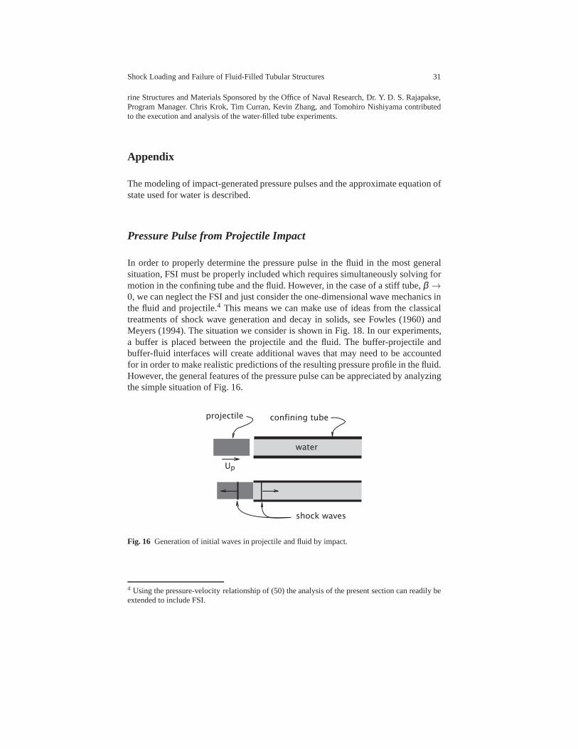
0, we can neglect the FSI and just consider the one-dimensional wave mechanics inthe fluid and projectile.4 This means we can make use of ideas from the classicaltreatments of shock wave generation and decay in solids, seeFowles (1960) andMeyers (1994). The situation we consider is shown in Fig. 18.In our experiments,a buffer is placed between the projectile and the fluid. The buffer-projectile andbuffer-fluid interfaces will create additional waves that may need to be accountedfor in order to make realistic predictions of the resulting pressure profile in the fluid.However, the general features of the pressure pulse can be appreciated by analyzingthe simple situation of Fig. 16.
projectile
water
confining tube
Up
shock waves
Fig. 16 Generation of initial waves in projectile and fluid by impact.
4 Using the pressure-velocity relationship of (50) the analysis of the present section can readily beextended to include FSI.

32 Joseph E. Shepherd and Kazuaki Inaba
The initial impact creates a shock wave with an amplitude determined by theimpact velocity and the acoustic impedancesρa of the projectile and fluid. Thepressure-velocity matching method (Meyers, 1994) can be used to construct thesolution by assuming simple waves in both fluid,
∆P= (ρa) f ∆u , (55)
and projectile,
∆P=−(ρa)p∆u . (56)
For the case of a steel projectile impacting water, the results are shown in Fig. 17.The pressure amplitude∆P of the initial wave in the water is proportional to thevelocity of the projectile before impact,
∆P=(ρa)p(ρa)w
(ρa)p+(ρa)wVp . (57)
As shown, the impedance of steel is much higher than that of water which leads tothe approximation,
∆P≈ (ρa)wVp . (58)
The projectile begins slowing down immediately after impact creating expansion
Fig. 17 Pressure-velocity diagram for computing peak pressure dueto a steel projectile impactingon water. The case of a 15 m/s projectile is shown.
waves that follow the initial compression wave in the water.The water is treated as

Shock Loading and Failure of Fluid-Filled Tubular Structures 33
x
t
shock
piston
Fig. 18 Wave system created by reverberation following impact of the projectile on the fluid sur-face.
compressible using the Tait equation of state described in the subsequent section,
P= P(ρ ,s) . (59)
For small projectile velocities relative to the sound speedin the projectile, there aremany reverberations of the waves within the projectile during the characteristic timeof slowing. This means that the projectile can be approximately treated as a rigidbody and treated with the methods of Newtonian mechanics. This idea has beenused by a number of researchers to develop simple analytical(Deshpande et al.,2006, Espinosa et al., 2006) and numerical solutions (Skewset al., 2004) for thewave generation process. The equation of motion of the projectile is
MpdVp
dt=−Ap(P−P1) , (60)
whereP is the pressure on the water face of the projectile andP1 is the ambientpressure on the free (rear) surface of the projectile. For weak shock waves, we cantreat the motion in the water as approximately isentropic sothat the method of char-acteristics can be used to compute the relationship betweensound speedap and fluidvelocity up at the water face of the piston. For the Tait equation, this is
ap−n−1
2up = a1 , (61)
wheren is an empirical constant with a value of 7 for water. At the face of thepiston, the fluid velocity is the same as the piston velocity so that changes in thepiston velocity are related to changes in the sound speed by
34 Joseph E. Shepherd and Kazuaki Inaba
dVp = dup , (62)
=2
n−1dap . (63)
For weak shock waves, the motion is isentropic and the changes in sound speed canbe uniquely related to changes in pressure through the equation of state,
dap =
(∂a∂P
)
sdP . (64)
This results in a simple ordinary differential equation forthe pressure difference∆Pp = Pp−P1 at the water face of the piston,
d∆Pp
dt=−
n−12
(∂P∂a
)
s
Ap
Mp∆Pp . (65)
The solution to this is
∆Pp(t) = ∆Pp(0)exp(−t/τ) , (66)
where the time constant is
τ =Mp
Ap
(∂P∂a
)
s
n−12
. (67)
The initial velocity Vp(0) and pressure∆Pp(0) are determined by the initial impactanalysis of (58). If we neglect the dependence of the characteristic speeds on am-plitude, the temporal variation of pressure on the face of the piston will also be thetemporal variation behind the wave. In experiments, the pressure behind the leadingfront will show a series of steps due to the discrete wave interactions at the interfacesbetween buffer, water, and projectile.
An example of the comparison of this model with the measured pressure is shownin Fig. 19. The peak pressure of 27.4 MPa was computed using (58) and the projec-tile initial speed of 18.5 m/s. A time constant ofτ = 0.41 ms was computed using(67) and the projectile length of 75 mm. The model does remarkably well asidefrom the obvious differences in the first 200µs due to wave motion in the bufferand projectile.
Tait Equation of State
The Tait equation of state is a simple analytic model that is useful for modeling acompressible liquid like water under modest compression. Experimental observa-

Shock Loading and Failure of Fluid-Filled Tubular Structures 35
0
5
10
15
20
25
30
35
40
-0.1 0 0.1 0.2 0.3 0.4 0.5 0.6 0.7 0.8
pre
ssu
re (
MP
a)
time (ms)
12.5 mm wall shot62
Fig. 19 Comparison of measured and model pressure for water in a 12.5mm thick steel tube andan 0.67 kg steel impactor with an initial speed of 18.5 m/s.
tions suggest that the isentropic compressibility can be described by the followingempirical formula,
−1υ
(∂υ∂P
)
s=
1n(P+B)
, (68)
wheren andB are empirical constants,B = 2.995× 10⁸ Pa andn = 7 for water.From the definition of sound speed,
a2 =−υ2(
∂P∂υ
)
s, (69)
we have that
a2 = nυ(P+B) . (70)
This leads to the following differential equation for pressure,
dPP+B
=−ndυυ
, (71)
which can be integrated to yield
P= B[(υ1
υ
)n−1]
, (72)

36 Joseph E. Shepherd and Kazuaki Inaba
or as a function of sound speed
P= B
[(ρ1a2
nB
) nn−1
−1
]
. (73)
The reference density isρ1 = 953.26 kg/m3 and the resulting reference sound speedis a1 = 1483 m/s. Using the expression for pressure, we can rewritethe sound speedas
a2 = nBυ1
(υ1
υ
)n−1. (74)
In the derivation of the piston motion, we need the derivative of the pressure withrespect to the sound speed,
(∂P∂a
)
s=
2nn−1
P+Ba
. (75)
Evaluating this at the nominal initial conditions, we obtain the value
(∂P∂a
)
s= 4.714×10⁵ Pa⋅s⋅m−1 . (76)
A short table of compressed water states estimated by the Tait equation are givenin Table 3 for the parametersρ1 = 953.263,B = 2.995× 10⁸, n = 7.
Table 3 Compressed liquid water states estimated by the Tait equation.
a P ρ/ρ1 up Us(m/s) (bar) (m/s) (m/s)
1483.3 1 1.0001 0.10 1483.201503 95 1.0045 6.67 1496.331528 216 1.0100 15.00 1513.001553 340 1.0155 23.34 1529.671578 467 1.0209 31.68 1546.341603 596 1.0263 40.02 1563.011628 728 1.0316 48.36 1579.681653 863 1.0368 56.72 1596.361678 1001 1.0420 65.07 1613.04
Shock Loading and Failure of Fluid-Filled Tubular Structures 37
Shock Hugoniot for Water
Shock wave researchers conventionally represent theHugoniotor locus of shockstates using relationships between the fluid velocity up and the shock velocity Us(Marsh, 1980). A typical empirical relationship used to correlate data is Us = ao +sup. For water, fitting the Nagayama et al. (2002) data gives the parameters ofao =1450 ands = 1.99. Using the shock jump conditions in the form:
Us = υ1
√P−P1
υ1−υ, (77)
up =√
(P−P1)(υ1−υ) . (78)
For the Tait equation of state over the range of interest in the present study (P <1 GPa), the Us-up relationship is highly linear and the fitting coefficients are ao =1484 m/s ands = 1.974. This is consistent with the evaluation of Nagayama et al.(2002) who also show that the irreversible temperature riseis on the order of 10∘Cat 1 GPa so that the Hugoniot can be reasonably approximated by the isentrope aswe have done using the Tait equation.
References
M. Arienti, P. Hung, E. Morano, and J. E. Shepherd. A level setapproach toEulerian-Lagrangian coupling.J. Computational Physics, 185:213–251, 2003.
R. M. Beam. Finite amplitude waves in fluid-filled elastic tubes: Wave distortion,shock waves, and korotkoff sounds. Technical Report TN D-4803, NASA, 1968.
W. M. Beltman and J.E. Shepherd. Linear elastic response of tubes to internal det-onation loading.Journal of Sound and Vibration, 252(4):617–655, 2002.
W. M. Beltman, E. Burcsu, J.E. Shepherd, and L. Zuhal. The structural response ofcylindrical shells to internal shock loading.Journal of Pressure Vessel Technol-ogy, pages 315–322, 1999.
R. A. Benham and T.A. Duffey. Experimental-theoretical correlation on the contain-ment of explosions in cylindrical vessels.Int. J. Mech. Sci., 16:549–558, 1974.
P.G. Bhuta. Transient response of a thin elastic cylindrical shell to a moving shockwave.J. Acoustical Soc. America, 35(1):25–30, 1963.
P. Chambers, H. Sandusky, F. Zerilli, K. Rye, R. Tussing, andJ. Forbes. Pressuremeasurements on a deforming surface in response to an underwater explosion ina water-filled aluminum tube.Shock and Vibration, 8:1–7, 2001.
T. W. Chao. Gaseous detonation-driven fracture of tubes. PhD thesis, CaliforniaInstitute of Technology, 2004.
T. W. Chao and J. E. Shepherd. Comparison of fracture response of preflawedtubes under internal static and detonation loading.Journal of Pressure VesselTechnology, 126(3):345–353, August 2004.

38 Joseph E. Shepherd and Kazuaki Inaba
T. W. Chao and J. E. Shepherd. Fracture response of externally flawed aluminumcylindrical shells under internal gaseous detonation loading. International Jour-nal of Fracture, 134(1):59–90, July 2005a.
T. W. Chao and J.E. Shepherd. Detonation loading of tubes in the modified shearwave regime. In Z. Jiang, editor,Proceedings of the 24th International Sympo-sium on Shock Waves, volume 2, pages 865–870. Springer, 2005b.
D. Coker and A. J. Rosakis. Experimental observations of intersonic crack growth inasymmetrically loaded unidirectional composite plates.Philosophical MagazineA-Physics of Condensed Matter Structure Defects And Mechanical Properties,81:571–595, 2001.
R.H. Cole.Underwater Explosions. Dover, New York, NY, 1965.VA Del Grosso. Analysis of multimodel acoustic propagationin liquid cylinders
with realistic boundary conditions - application to sound speed and absorptionmeasurements.Acustica, 24(6):299–311, 1971.
V. S. Deshpande, A. Heaver, and N. A. Fleck. An underwater shock simulator.Proc.R. Soc. A, 462:1021–1041, 2006.
T.A. Duffey. Approximate solutions of an impulsively loaded long cylinder gov-erned by an elastic-plastic material law.Acta Mechanica., 11:45–57, 1971.
T.A. Duffey and R. Krieg. Effects of strain hardening and strain rate sensitivity onthe transient response of elastic-plastic rings and cylinders.Int. J. Mech. Sci., 11:825–844, 1969.
T.A. Duffey and D. Mitchell. Containment of explosions in cylindrical shells. Int.J. Mech. Sci., 15:237–249, 1973.
T.A. Duffey, E.A. Rodriguez, and C. Romero. Design of pressure vessels for high-strain rate loading: dynamic pressure and failure criteria. Bulletin 477, WeldingResearch Council, P.O. Box 1942, New York, NY, 2002.
H.D. Espinosa, S. Lee, and N. Moldovan. A novel fluid structure interaction ex-periment to investigate deformation of structural elements subjected to impulsiveloading.Experimental Mechanics, 46:805824, 2006.
F. Fanous and L. Greiman. Simplified analysis for impulsively loaded shells.Jour-nal of Structural Engineering, 114:885–899, April 1988.
J. R. Florek and H. Benaroya. Pulse-pressure loading effects on aviation and generalengineering structures.Journal of Sound and Vibration, 284:421–453, 2005.
G. R. Fowles. Attenuation of a shock wave produced in a solid by a flying plate.J.Appl. Physics, 31(655-661), 1960.
C. R. Fuller and F. J. Fahy. Characteristics of wave propagation and energy distri-butions in cylindrical elastic shells filled with fluid.J. Sound Vibration, pages501–518, 1982.
J Gale and I Tiselj. Godunov’s method for simulations of fluid-structure interactionin piping systems. 130(3):031304, 2008.
R. P. Greenwood. German work on grp design.Composites, 7:175–184, 1977.J.B. Grotberg and O. E. Jensen. Biofluid mechanics in flexibletubes. Annual Re-
views of Fluid Mechanics, 36:121–147, 2004.P. G. Hodge. The influence of blast characteristics on final deformation of circular
cylindrical shells.Journal of Applied Mechanics, 284:617–624, December 1956.

Shock Loading and Failure of Fluid-Filled Tubular Structures 39
M. S. Howe.Acoustics of Fluid-Structure Interaction. Cambridge University Press,1998.
D. Hull and T. W. Clyne. An Introduction to Composite Materials. CambridgeUniversity Press, 2nd edition, 1996.
K. Inaba and J. E. Shepherd. Flexural waves in fluid-filled tubes subject to axialimpact. InProceedings of the ASME Pressure Vessels and Piping Conference.July 27-31, Chicago, IL USA, 2008a. PVP2008-61672.
K. Inaba and J. E. Shepherd. Impact generated stress waves and coupled fluid-structure responses. InProceedings of the SEM XI International Congress &Exposition on Experimental and Applied Mechanics. June 2-5, Orlando, FL USA,2008b. Paper 136.
N. Joukowsky.Uber den hydraulischen stoss in wasserleitungsrohren.Memoires delAacademie Imperiale des Sciences de St. Petersbourg, 1900. series 8, 9.
M. C. Junger and D. Feit.Sound, Structures, and Their Interaction. MIT Press,1986.
V.K. Kedrinsky.Hydrodynamics of Explosion. Springer, 2005.J. T. Kenney. Steady state vibrations of beam on elastic foundation for moving load.
J. Applied Mechanics. Trans. ASME, 21(4):359–364, 1954.H. Kolsky. Stress Waves in Solids. Dover Publications, Inc., 1963.D. Korteweg. Uber die fortphlanzungsgeschwindigkeit des schalles in elastisches
rohren.Annalen der Physik und Chemie, 9 floge, 5:525–542, 1878.O.E. Kosing and B. W. Skews. An investigation of high speed forming of circular
plates in a liquid shock tube.Int. J. Impact Engng, 21(9):80181, 1998.LD Lafleur and FD Shields. Low-frequency propagation modes in a liquid-filled
elastic tube waveguide.J. Acoust. Soc. Am., 97(3):1435–1445, 1995.K. B. Lewis and N. V. Nechitailo. Transient resonance in hypervelocity launchers
at critical velocities.IEEE Transactions on Electromagnetics, 43:157–162, 2007.QS Li, K Yang, and L Zhang. Analytical solution for fluid-structure interaction in
liquid-filled pipes subjected to impact-induced water hammer. Journal of Engi-neering Mechanics, 129(12):1408–1417, 2003.
Z. Liang, J. Karnesky, and J. E. Shepherd. Structural response to reflected deto-nations and deflagration-to-detonation transition in H2-N2O mixtures. TechnicalReport FM2006.003, California Institute of Technology, 2006a. Revised May 23,2007.
Z. Liang, J. Karnesky, J.E. Shepherd, and R. Deiterding. Experimental measure-ments and numerical validation of reflected detonations in C2H4-O2 mixtures.Technical Report FM2006.009, Graduate Aeronautical Laboratories, CaliforniaInsititute of Technology, 2006b.
J. Lighthill. Waves in Fluids. Cambridge University Press, 1978.S. P. Marsh, editor.LASL shock hugoniot data. University of California Press,
Berkeley, CA, 1980.M. A. Meyers.Dynamic behavior of materials. John Wiley & Sons, 1994.K. Nagayama, Y. Mori, K. Shimada, and M. Nakahara. Shock hugoniot compression
curve for water up to 1 GPa by using a compressed gas gun.Journal of AppliedPhysics, 91(1), 2002.

40 Joseph E. Shepherd and Kazuaki Inaba
ONR. Underwater explosion research: A compendium of the British and Ameri-can reports, Vol. I The shock wave, Vol. II-The gas globe, Vol. III-The damageprocess. Technical report, Office of Naval Research, Washington, DC., 1950.
KH Parker. A brief history of arterial wave mechanics.Med. Biol. Eng. Comput.,47(2):111–118, 2009.
R. J. Pinnington. The axisymmetric wave transmission properties of pressurizedflexible tubes.Journal of Sound and Vibration, 204:271–289, 1997.
F. Pintgen and J. E. Shepherd. Elastic and plastic structural response of thin tubesto deflagration-to-detonation transition events. Technical Report FM2005.008,California Institute of Technology, March 2006.
R. Rajendran and K. Narasimhan. Deformation and fracture behaviour of platespecimens subjected to underwater explosion - a review.International Journal ofImpact Engineering, 32:1945–1963, 2006.
E.A. Rodriguez and T.A. Duffey. Fracture-safe and fatigue design criteria fordetonation-induced pressure loading in containment vessels. Bulletin 494, Weld-ing Research Council, P.O. Box 1942, New York, NY, 2004.
H. Sandusky, P. Chambers, F. Zerilli, L. Fabini, and W. Gottwald. Dynamic mea-surements of plastic deformation in a water-filled aluminumtube in response todetonation of a small explosive charge.Shock and Vibration, 6:125–132, 1999.
J. E. Shepherd. Structural response of piping to internal gas detonation.Journal ofPressure Vessel Technology, 2009. in press.
J.E. Shepherd, J. Karnesky, F. Pintgen, and J. C. Krok. Experimental measurementsof strains and blast waves resulting from detonations in tubes. Technical ReportFM2006.010, Graduate Aeronautical Laboratories, California Insititute of Tech-nology, June 2008.
T. E. Simkins. The influence of transient flexural waves on dynamic strains in cylin-ders.J. Applied Mechanics, 62:262–265, 1995.
T. E. Simkins, G. A. Pflegl, and E. G. Stilson. Dynamic strainsin a 60-mm guntube: An experimental study.J. Sound Vibration, 168:549–557, 1993.
B. K. Sinha, T. J. Plona, S. Kostek, and S.-K. Chang. Axisymmetric wave propa-gation in fluid-loaded cylindrical shells.J. Acoust. Soc. Am., 132(2):1132–1143,August 1992.
R. Skalak. An extension to the theory of water hammer.Transactions of the ASME,78:105–116, January 1956.
B.W. Skews, E. Kosing, and R.J. Hattingh. Use of a liquid shock tube as a devicefor the study of material deformation under impulsive loading conditions.Proc.Instn. Mech. Engrs. J. Mechanical Engineering Science, 218:39–51, 2004.
W. R. Smith. Fast loading of metals with a shock tube: Application to aluminum. InProceedings of the 15th International Symposium on Shock Waves, Berkeley CA1985, pages 541–545. Stanford University Press, 1986.
W. R. Smith. Modeling inelastic wall response of a thin-walled cylindrical tubeto shock waves. InProceedings of the 17th International Symposium on ShockWaves, Bethlehem PA 1989, pages 558–563, New York, NY, 1990. American In-stitute of Physics.
Shock Loading and Failure of Fluid-Filled Tubular Structures 41
B. Spencer and D. Hull. Effect of winding angle on the failureof filament woundpipe. Composites, 9:263–271, 1978.
S. Tang. Dynamic response of a tube under moving pressure. InProceedings ofthe American Society of Civil Engineers, volume 5, pages 97–122. EngineeringMechanics Division, October 1965.
A. S. Tijsseling. Fluid-structure interaction in liquid-filled pipe systems: a review.Journal of Fluids and Structures, 10:109–146, 1996.
A. S. Tijsseling. Exact solution of linear hyperbolic four-equation system in axialliquid-pipe vibration.Jourbal of Fluids and Structures, 18:179–196, 2003.
A. S. Tijsseling. Water hammer with fluid-structure interaction in thick-walledpipes.Computers and Structures, 85:844–851, 2007.
A. S. Tijsseling, M. F. Lambert, A. R. Simpson, M. L. Stephens, John P. Vitkovsky,and A. Bergant. Skalak’s extended theory of water hammer.J. Sound Vibration,310:718–728, 2008.
D.H. Trevena.Cavitation and Tension in Liquids. Adam Hilger, 1987.A. B. Wardlaw, Jr. and J. Alan Luton. Fluid structure interaction mechanisms for
close-in explosions.Shock and Vibration, 7:265–275, 2000.G. Z. Watters.Analysis and Control of Unsteady Flow in Pipelines. Butterworth
Publishers, MA, 1984.DC Wiggert and AS Tijsseling. Fluid transients and fluid-structure interaction in
flexible liquid-filled piping.Applied Mechanics Reviews, 54(5):455–481, 2001.DC Wiggert, FJ Hatfield, and S Stuckenbruck. Analysis of liquid and structural
transients by the method of characteristics.J. Fluids Eng., 109(2):161–165,1987.E. B. Wylie and V. L. Streeter.Fluid Transients in Systems. Prentice-Hall, Inc., NJ,
1993.Z. Xue and J. W. Hutchinson. A comparative study of impulse-resistant metal sand-
wich plates.International Journal of Impact Engineering, 30:1283–1305, 2004.