Experimental Study of Concrete Filled Tubular Short Columns · PDF filecolumns composed of...
7
International Research Journal of Engineering and Technology (IRJET) e-ISSN: 2395-0056 Volume: 04 Issue: 08 | Aug -2017 www.irjet.net p-ISSN: 2395-0072 © 2017, IRJET | Impact Factor value: 5.181 | ISO 9001:2008 Certified Journal | Page 1719 Experimental Study of Concrete Filled Tubular Short Columns Babita Kirodiwal 1 , Prof. G.R. Patil 2 1 PG student, Department of civil engineering, JSPM’S Rajarshi shahu college of engg, Pune, MH, India 2 Associate professor, Department of civil engineering, JSPM’S Rajarshi shahu college of engg, Pune, MH, India ---------------------------------------------------------------------***--------------------------------------------------------------------- Abstract - Concrete Filled Steel Tube structural system is a system based on filling steel tubes with concrete. The CFST structural system promises excellent structural characteristics, like strength, deformation capacity, and fire resistance for use in many fields of construction. Composite columns composed of concrete-filled steel tubes have become increasingly popular in structural applications around the world. This type of columns can offer many advantages like high strength, ductility and large energy absorption capacity with possible use of simple standardized connections. In these days possibility to produce concretes with higher compressive strengths allows the design of more slender columns, which permits more usable floor space. The aim of my project is to improve the current knowledge of the mechanical behavior of CFST columns to make a more efficient. In this study, different types of geometrical shapes of CFST are considered. A great deal of theoretical and experimental work has been carried out on selected sample of columns. Key Words: Composite column, Design codes, BS-5400, Axial loading, Concrete Grade. 1. INTRODUCTION Structural member is generally made up of either steel or concrete or both steel and concrete as composite. The steel member shows high tensile strength and ductility on the other hand, concrete member having the advantages of high compressive strength and stiffness. if steel concrete member is designed to utilize these structural properties of both materials efficiently, then the steel concrete composite member exhibits the advantageous qualities of both materials 1.1 DEFINATION Columns are structural members, which are subjected to axial forces. It is for this reason that complete interaction between the structural components of the column namely the steel and the concrete element is achieved through direct interface bond. Structural members are generally made up of either steel or concrete or both steel and concrete as composite. The steel members show high tensile strength and ductility on the other, hand concrete members have the advantages of high compressive strength and stiffness. Composite column is a compression member comprising of concrete and steel in the form of other than reinforcing bars, composite column can be of two types. 1.2 Types of Concrete Filled Columns There are two main categories of composite columns, namely the concrete encased and the concrete filled columns. Encased composite column consist of structural shapes surrounded by concrete. The concrete requires vertical and horizontal bar reinforcement to sustain the encasement of the steel core. Shear connectors may be needed as well to ensure interaction and transfer between the steel shape and the concrete encasement. Filled composite columns may be the most efficient application of materials for column cross sections. Their steel shell can be a pipe or tubing or hallow section fabricated form plates. It provides forms the inexpensive concrete core and increases the strength and the stiffness of the column. Figure 1 presents the filled type, that is, a structural pipe or tube filled by concrete. Figure 2 shows different types of filled encased columns According to shape of column Circular Rectangular Square According to depth of concrete filling Partially filled concrete steel column Fully filled concrete steel column Fig. 1. Section of concrete filled steel columns.
Transcript of Experimental Study of Concrete Filled Tubular Short Columns · PDF filecolumns composed of...
International Research Journal of Engineering and Technology (IRJET) e-ISSN: 2395-0056
Volume: 04 Issue: 08 | Aug -2017 www.irjet.net p-ISSN: 2395-0072
© 2017, IRJET | Impact Factor value: 5.181 | ISO 9001:2008 Certified Journal | Page 1719
Experimental Study of Concrete Filled Tubular Short Columns
Babita Kirodiwal1, Prof. G.R. Patil2
1PG student, Department of civil engineering, JSPM’S Rajarshi shahu college of engg, Pune, MH, India 2Associate professor, Department of civil engineering, JSPM’S Rajarshi shahu college of engg, Pune, MH, India
---------------------------------------------------------------------***---------------------------------------------------------------------Abstract - Concrete Filled Steel Tube structural system is a system based on filling steel tubes with concrete. The CFST structural system promises excellent structural characteristics, like strength, deformation capacity, and fire resistance for use in many fields of construction. Composite columns composed of concrete-filled steel tubes have become increasingly popular in structural applications around the world. This type of columns can offer many advantages like high strength, ductility and large energy absorption capacity with possible use of simple standardized connections. In these days possibility to produce concretes with higher compressive strengths allows the design of more slender columns, which permits more usable floor space. The aim of my project is to improve the current knowledge of the mechanical behavior of CFST columns to make a more efficient. In this study, different types of geometrical shapes of CFST are considered. A great deal of theoretical and experimental work has been carried out on selected sample of columns. Key Words: Composite column, Design codes, BS-5400, Axial loading, Concrete Grade. 1. INTRODUCTION Structural member is generally made up of either steel or concrete or both steel and concrete as composite. The steel member shows high tensile strength and ductility on the other hand, concrete member having the advantages of high compressive strength and stiffness. if steel concrete member is designed to utilize these structural properties of both materials efficiently, then the steel concrete composite member exhibits the advantageous qualities of both materials 1.1 DEFINATION Columns are structural members, which are subjected to axial forces. It is for this reason that complete interaction between the structural components of the column namely the steel and the concrete element is achieved through direct interface bond. Structural members are generally made up of either steel or concrete or both steel and concrete as composite. The steel members show high tensile strength and ductility on the other, hand concrete members have the advantages of high compressive strength and stiffness. Composite column is a compression member comprising of
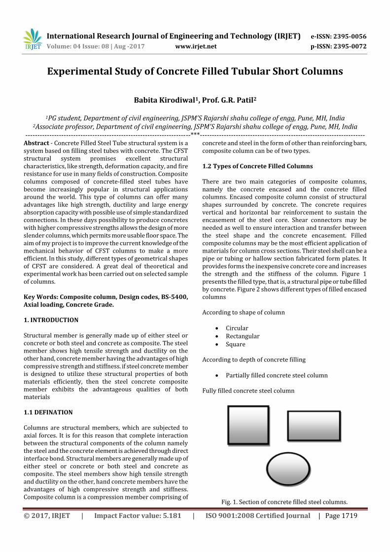
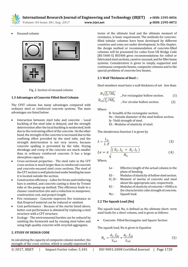
concrete and steel in the form of other than reinforcing bars, composite column can be of two types. 1.2 Types of Concrete Filled Columns There are two main categories of composite columns, namely the concrete encased and the concrete filled columns. Encased composite column consist of structural shapes surrounded by concrete. The concrete requires vertical and horizontal bar reinforcement to sustain the encasement of the steel core. Shear connectors may be needed as well to ensure interaction and transfer between the steel shape and the concrete encasement. Filled composite columns may be the most efficient application of materials for column cross sections. Their steel shell can be a pipe or tubing or hallow section fabricated form plates. It provides forms the inexpensive concrete core and increases the strength and the stiffness of the column. Figure 1 presents the filled type, that is, a structural pipe or tube filled by concrete. Figure 2 shows different types of filled encased columns According to shape of column
Circular Rectangular Square
According to depth of concrete filling
Partially filled concrete steel column Fully filled concrete steel column
Fig. 1. Section of concrete filled steel columns.
International Research Journal of Engineering and Technology (IRJET) e-ISSN: 2395-0056
Volume: 04 Issue: 08 | Aug -2017 www.irjet.net p-ISSN: 2395-0072
© 2017, IRJET | Impact Factor value: 5.181 | ISO 9001:2008 Certified Journal | Page 1720
Encased column
Fig. 2. Section of encased column 1.3 Advantages of Concrete Filled Steel Column The CFST column has many advantages compared with ordinary steel or reinforced concrete systems. The main advantages are listed below: Interaction between steel tube and concrete - Local
buckling of the steel tube is delayed, and the strength deterioration after the local buckling is moderated, both due to the restraining effect of the concrete. On the other hand, the strength of the concrete is increased due to the confining effect provided by the steel tube, and the strength deterioration is not very severe, because concrete spalling is prevented by the tube. Drying shrinkage and creep of the concrete are much smaller than in ordinary reinforced concrete. It has a large absorption capacity.
Cross-sectional properties - The steel ratio in the CFT cross section is much larger than in reinforced concrete and concrete-encased steel cross sections. The steel of the CFT section is well plasticized under bending because it is located outside the section.
Construction efficiency - Labor for forms and reinforcing bars is omitted, and concrete casting is done by Tremie tube or the pump-up method. This efficiency leads to a cleaner construction site and a reduction in manpower, construction cost, and project length.
Fire resistance - Concrete improves fire resistance so that fireproof material can be reduced or omitted.
Cost performance - Because of the merits listed above, better cost performance is obtained by replacing a steel structure with a CFT structure.
Ecology - The environmental burden can be reduced by omitting the formwork and by reusing steel tubes and using high-quality concrete with recycled aggregates.
2. STUDY OF DESIGN CODE In calculating the capacity of composite column member, the strength of the cross section, which is usually expressed in
terms of the ultimate load and the ultimate moment of resistance, is basic requirement. The methods for concrete-filled tubular columns have been developed by different countries and some are under development. In this chapter, the design method or recommendation of concrete-filled columns will be presented for codes from UK Bridge Code [BS-5400-5] BS5400 gives recommendations for rolled or fabricated steel sections, cased or uncased, and for filler beam systems. Consideration is given to simply supported and continuous composite beams, composite columns and to the special problems of concrete box beams. 2.1 Wall Thickness of Steel :- Steel members must have a wall thickness of not less than:
…For rectangular hollow section. (1)
…For circular hollow section. (2) Where
B- breadth of the rectangular section. De - Outside diameter of the steel hollow section. fy- Yield strength of steel. ES - Modulus of elasticity of steel.
The slenderness function λ is given by
Where,
Le - Effective length of the actual column in the plane of bending.
ES - Modulus of elasticity of hollow steel section. IC, IS - Moment of inertia of concrete and steel
about the appropriate axis, respectively. EC - Modulus of elasticity of concrete = 450fcu is
the characteristic cube strength of concrete. Nu - Squash load.
2.2 The Squash Load (Nu) The squash load, Nu, is defined as the ultimate short- term axial loads for a short column, and is given as follows: Concrete- Filled Rectangular and Square Section The squash load, Nu is given in Equation
International Research Journal of Engineering and Technology (IRJET) e-ISSN: 2395-0056
Volume: 04 Issue: 08 | Aug -2017 www.irjet.net p-ISSN: 2395-0072
© 2017, IRJET | Impact Factor value: 5.181 | ISO 9001:2008 Certified Journal | Page 1721
Where, AC, AS - Cross sectional areas of concrete and
structural steel, respectively. fck, fsk- Characteristic strengths of concrete and
structural steel, respectively.
- Material partial safety factors of concrete and structural steel taken as 1.5 and 1.1 respectively.
Where,
fcu- The characteristic 28-day cube strength of concrete.
fy- The nominal yield strength of structural steel.
In applying the material partial safety factors, the squash load Nu, will be,
Concrete-Filled Circular Section The squash load, Nu will be given as:
Where,
Where,
fcc- Enhanced characteristic strength of triaxiallycontained concrete.
fy- Reduced nominal yield strength of the steel casing.
3. PROPERTIES OF MATERIAL Material testing was conducted to investigate the properties of the material such as cement, fine aggregates and course aggregates which are used for casting the specimens. Various laboratory tests were performed and the test results obtained were compared with Indian standard values. The test results are listed in below tables. A. Cement OPC-43 grades available in local market is used
Table 1 Properties of Cement
Name of the property Result Limits
Specific Gravity 3.15 3.15
Fineness Modulus 2.33 2.2-2.4
Consistency 32% 30-35%
Initial setting time 35mins 30mins
Final setting time 360mins 600mins
B. Aggregates
Table 2 Properties of Aggregates
Name of the property Result Limits
Fineness modulus of fine 2.68 2.6-2.7
Fineness modulus of course
2.47 6.6-8
Silt content 2.4% 5%
Specific gravity of C.A 2.70 2.5-3
Specific gravity of F.A 2.63 2.6-3
C. Concrete strength
Table 3 Compressive Strength of Concrete
Grade of concrete Fck(MPa)
M20 26.67
M25 29.03
M30 31.03
a. Average strength of the three cubes at end of 28days
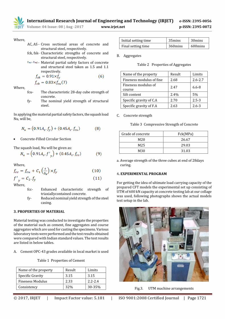
curing. 4. EXPERIMENTAL PROGRAM For getting the idea of ultimate load carrying capacity of the prepared CFT models the experimental set up consisting of UTM of 600 kN capacity at concrete testing lab at our collage was used, following photographs shows the actual models test setup in the lab.
Fig.3. UTM machine arrangements
International Research Journal of Engineering and Technology (IRJET) e-ISSN: 2395-0056
Volume: 04 Issue: 08 | Aug -2017 www.irjet.net p-ISSN: 2395-0072
© 2017, IRJET | Impact Factor value: 5.181 | ISO 9001:2008 Certified Journal | Page 1722
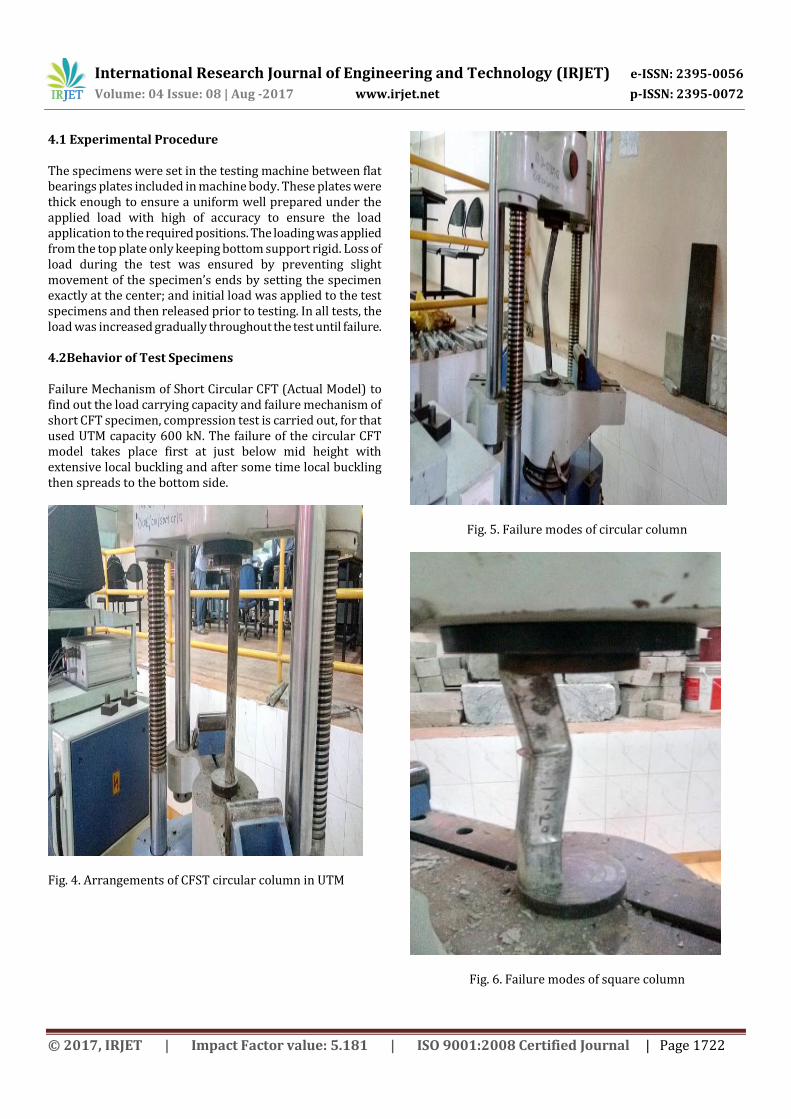
4.1 Experimental Procedure The specimens were set in the testing machine between flat bearings plates included in machine body. These plates were thick enough to ensure a uniform well prepared under the applied load with high of accuracy to ensure the load application to the required positions. The loading was applied from the top plate only keeping bottom support rigid. Loss of load during the test was ensured by preventing slight movement of the specimen’s ends by setting the specimen exactly at the center; and initial load was applied to the test specimens and then released prior to testing. In all tests, the load was increased gradually throughout the test until failure. 4.2Behavior of Test Specimens Failure Mechanism of Short Circular CFT (Actual Model) to find out the load carrying capacity and failure mechanism of short CFT specimen, compression test is carried out, for that used UTM capacity 600 kN. The failure of the circular CFT model takes place first at just below mid height with extensive local buckling and after some time local buckling then spreads to the bottom side.
Fig. 4. Arrangements of CFST circular column in UTM
Fig. 5. Failure modes of circular column
Fig. 6. Failure modes of square column
International Research Journal of Engineering and Technology (IRJET) e-ISSN: 2395-0056
Volume: 04 Issue: 08 | Aug -2017 www.irjet.net p-ISSN: 2395-0072
© 2017, IRJET | Impact Factor value: 5.181 | ISO 9001:2008 Certified Journal | Page 1723
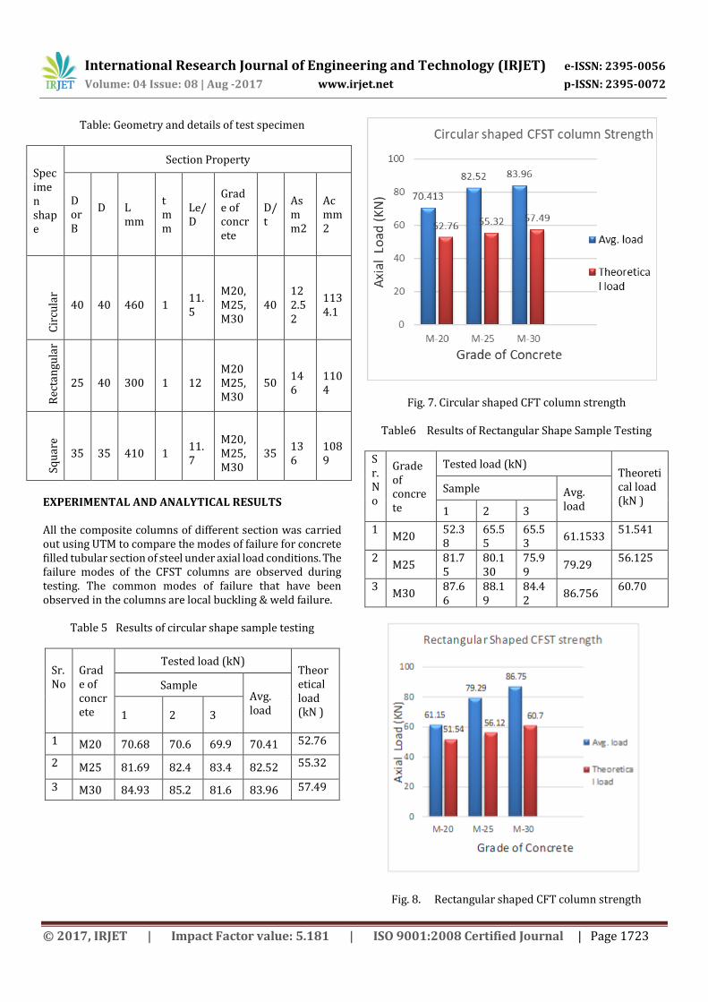
Table: Geometry and details of test specimen
Specimen shape
Section Property
D or B
D
L mm
t mm
Le/D
Grade of concrete
D/t
As mm2
Ac mm2
Cir
cula
r 40
40
460
1
11.5
M20, M25, M30
40
122.52
1134.1
Rec
tan
gula
r
25
40
300
1
12
M20 M25, M30
50
146
1104
Squ
are
35 35
410
1
11.7
M20, M25, M30
35
136
1089
EXPERIMENTAL AND ANALYTICAL RESULTS All the composite columns of different section was carried out using UTM to compare the modes of failure for concrete filled tubular section of steel under axial load conditions. The failure modes of the CFST columns are observed during testing. The common modes of failure that have been observed in the columns are local buckling & weld failure.
Table 5 Results of circular shape sample testing
Sr. No
Grade of concrete
Tested load (kN) Theoretical load (kN )
Sample Avg. load 1 2 3
1 M20 70.68 70.6 69.9 70.41 52.76
2 M25 81.69 82.4 83.4 82.52 55.32
3 M30 84.93 85.2 81.6 83.96 57.49
Fig. 7. Circular shaped CFT column strength
Table6 Results of Rectangular Shape Sample Testing Sr. No
Grade of concrete
Tested load (kN) Theoretical load (kN )
Sample Avg. load 1 2 3
1 M20
52.38
65.55
65.53
61.1533 51.541
2 M25
81.75
80.130
75.99
79.29 56.125
3 M30
87.66
88.19
84.42
86.756 60.70
Fig. 8. Rectangular shaped CFT column strength
International Research Journal of Engineering and Technology (IRJET) e-ISSN: 2395-0056
Volume: 04 Issue: 08 | Aug -2017 www.irjet.net p-ISSN: 2395-0072
© 2017, IRJET | Impact Factor value: 5.181 | ISO 9001:2008 Certified Journal | Page 1724
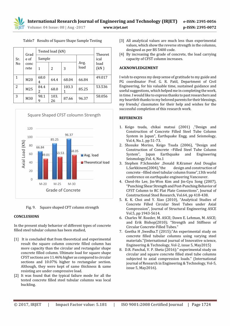
Table7 Results of Square Shape Sample Testing Sr. No
Grade of concrete
Tested load (kN) Theoretical load (kN )
Sample Avg. load 1 2 3
1 M20
68.04
64.4 68.04 66.84 49.017
2 M25
84.42
68.0 103.31
85.25 53.536
3 M30
98.19
103.26
87.66 96.37 58.056
66.84
85.25
96.37
49.0153.53
58.05
0
20
40
60
80
100
120
M-20 M-25 M-30
Axi
al L
oad
(K
N)
Grade of Concrete
Square Shaped CFST coloumn Strength
Avg. load
Theoretical load
Fig. 9. Square shaped CFT column strength
CONCLUSIONS In the present study behavior of different types of concrete filled steel tubular column has been studied, [1] It is concluded that from theoretical and experimental
result the square column concrete filled column has more capacity than the circular and rectangular shape concrete filled column. Ultimate load for square shape CFST sections are 11.46% higher as compared to circular sections and 10.07% higher to rectangular section. Although, they were kept of same thickness & same resisting are under compressive load.
[2] It was found that the typical failure mode for all the tested concrete filled steel tubular columns was local buckling.
[3] All analytical values are much less than experimental values, which show the reverse strength in the columns, designed as per BS 5400 code.
[4] By increasing the grade of concrete, the load carrying capacity of CFST column increases.
ACKNOWLEDGEMENT I wish to express my deep sense of gratitude to my guide and PG coordinator Prof. G. R. Patil, Department of Civil Engineering, for his valuable time, sustained guidance and useful suggestions, which helped me in completing the work, in time. I would like to express thanks to past researchers and my heartfelt thanks to my beloved parents for their blessings, my friends/ classmates for their help and wishes for the successful completion of this research work. REFERENCES
1. Keigo tsuda, chikai matsui (2001) ,“Design and
Construction of Concrete Filled Steel Tube Column System in Japan”, Earthquake Engg. and Seismology, Vol.4, No.1, pp 51-73.
2. Shosuke Morino, Keigo Tsuda (2006), “Design and Construction of Concrete –Filled Steel Tube Column System”, Japan Earthquake and Engineering Seismology,Vol. 4, No.1
3. Stephen P.Schneider ,Donald R.Kramer And Douglas L.Sarkkinem(2004),”the design and construction of concrete –filled steel tubular column frame”,13th world conference on earthquake engineering Vancouver.
4. Cheol-Ho Lee, Jin-Won Kim and Jin-Gyu Song (2007), “Punching Shear Strength and Post-Punching Behavior of CFST Column to RC Flat Plate Connections”, Journal of Constructional Steel Research, Vol.64, pp 418-438.
5. K. K. Choi and Y. Xiao (2010), “Analytical Studies of Concrete Filled Circular Steel Tubes under Axial Compression”, Journal of Structural Engineering ASCE Vol.5, pp 1943-5614.
6. Charles W. Roeder, M. ASCE; Dawn E. Lehman, M. ASCE; and Erik Bishop(2010); “Strength and Stiffness of Circular Concrete-Filled Tubes.”
7. Geetha H ,Swedha.T (2015);”An experimental study on concrete filled tubular columns using varying steel materials.”(International journal of Innovative science, Engineering & Technology, Vol-2, issue 5, May2015)
8. D.R. Panchal, V. P. Sheta (2016);” experimental study on circular and square concrete filled steel tube columns subjected to axial compression loads.” (International journal of Research in Engineering & Technology, Vol-5, issue 5, May2016).
International Research Journal of Engineering and Technology (IRJET) e-ISSN: 2395-0056
Volume: 04 Issue: 08 | Aug -2017 www.irjet.net p-ISSN: 2395-0072
© 2017, IRJET | Impact Factor value: 5.181 | ISO 9001:2008 Certified Journal | Page 1725
BIOGRAPHIES
Babita M. Kirodiwal, PG Student, Department of Civil (Structural) Engg. JSPM’S Rajarshi Shahu College of Engineering, Tathawade, Pune-411033
G. R. Patil, Associate professor and PG Coordinator, Department of Civil (Structural) Engg. JSPM’S Rajarshi Shahu College of Engineering, Tathawade, Pune-411033