Shkodra Project 2009-Eros Veizi
7
Hybrid fibre-coaxial Hybrid fiber-coaxial (HFC) refers to a telecommunications broadband network that combines optical fiber and coaxial cable. It requires a lot of work to set up a HFC ISP nowadays. I ‘ll try to display the main steps of this project.The main components are the Head-End,the fiber Nodes,amplifiers and Taps. So the two things that you have to do are : 1.To plan your Head –Office 2.To plan your distribuition network. We begin this work of planing and implementing a HFC Network in the city of Shkodra in 2009 and aftesr a year we were “online” with our areas. You will see below a few explanation about HFC technology,the HFC Network Diagram,and how to project an area of the city HFC network diagram The fiber optic network extends from the cable operators' master headend, sometimes to regional headends, and out to a neighborhood's hubsite, and finally to a coaxial cable node which serves anywhere from 25 to 2000 homes. A master headend will usually have satellite dishes for reception of distant video signals as well as IP aggregation routers. Some master headends also house telephony equipment for providing telecommunications services to the community. A regional or area headend/hub will receive the video signal from the master headend and add to it the public, educational, and government access (PEG) cable TV channels as required by local franchising authorities or insert targeted advertising that would appeal to a local area. The various services are encoded, modulated and upconverted onto radio frequency (RF) carriers, combined onto a single electrical signal and inserted into a broadband optical transmitter. This optical transmitter converts the electrical signal to a downstream optically modulated signal that is sent to the nodes. Fibre optic cables connect the headend or hub to optical nodes in a point-to-point or star topology, or in some cases, in a protected ring topology.
-
Upload
eros-veizi -
Category
Documents
-
view
41 -
download
4
description
Set up an HFC ISP in an albanian city.
Transcript of Shkodra Project 2009-Eros Veizi
Hybrid fibre-coaxial
Hybrid fiber-coaxial (HFC) refers to a telecommunications broadband network that combines optical fiber and coaxial cable. It requires a lot of work to set up a HFC ISP nowadays. I ‘ll try to display the main steps of this project.The main components are the Head-End,the fiber Nodes,amplifiers and Taps.
So the two things that you have to do are :
1.To plan your Head –Office
2.To plan your distribuition network.
We begin this work of planing and implementing a HFC Network in the city of Shkodra in 2009 and aftesr a year we were “online” with our areas.
You will see below a few explanation about HFC technology,the HFC Network Diagram,and how to project an area of the city
HFC network diagram
The fiber optic network extends from the cable operators' master headend, sometimes to regional headends, and out to a neighborhood's hubsite, and finally to a coaxial cable node which serves anywhere from 25 to 2000 homes. A master headend will usually have satellite dishes for reception of distant video signals as well as IP aggregation routers. Some master headends also house telephony equipment for providing telecommunications services to the community.
A regional or area headend/hub will receive the video signal from the master headend and add to it the public, educational, and government access (PEG) cable TV channels as required by local franchising authorities or insert targeted advertising that would appeal to a local area. The various services are encoded, modulated and upconverted onto radio frequency (RF) carriers, combined onto a single electrical signal and inserted into a broadband optical transmitter.
This optical transmitter converts the electrical signal to a downstream optically modulated signal that is sent to the nodes. Fibre optic cables connect the headend or hub to optical nodes in a point-to-point or star topology, or in some cases, in a protected ring topology.

Fiber optic nodes
A fiber optic node has a broadband optical receiver which is known as optical receivers, which convert the downstream optically modulated signal coming from the headend/hub to an electrical signal going to the homes. Today, the downstream signal is a RF modulated signal that typically begins at 50 MHz and ranges from 550–1000 MHz on the upper end. The fiber optic node also contains a reverse/return path transmitter that sends communication from the home back to the headend. In North America, this reverse signal is a modulated RF ranging from 5–42 MHz while in other parts of the world, the range is 5–65 MHz. Optical coupler is a part of node , which combine with optical receiver to form a node
The optical portion of the network provides a large amount of flexibility. If there are not many fiber-optic cables to the node, wavelength division multiplexing can be used to combine multiple optical signals onto the same fiber. Optical filters are used to combine and split optical wavelengths onto the single fiber. For example, the downstream signal could be on a wavelength at 1310 nm and the return signal could be on a wavelength at 1550 nm.
Final connection to homes
The coaxial portion of the network connects 25–2000 homes (500 is typical) in a tree-and-branch configuration off of the node. RF amplifiers are used at intervals to overcome cable attenuation and passive losses of the electrical signals caused by splitting or "tapping" the coaxial cable.
Trunk coaxial cables are connected to the optical node and form a coaxial backbone to which smaller distribution cables connect. Trunk cables also carry AC power which is added to the cable line at usually
either 60 or 90 V by a power supply and a power inserter. The power is added to the cable line so that trunk and distribution amplifiers do not need an individual, external power source.
From the trunk cables, smaller distribution cables are connected to a port of the trunk amplifier to carry the RF signal and the AC power down individual streets. If needed, line extenders, which are smaller distribution amplifiers, boost the signals to keep the power of the television signal at a level that the TV can accept. The distribution line is then "tapped" into and used to connect the individual drops to customer homes.
These taps pass the RF signal and block the AC power unless there are telephony devices that need the back-up power reliability provided by the coax power system. The tap terminates into a small coaxial drop using a standard screw type connector known as an “F” connector.
The drop is then connected to the house where a ground block protects the system from stray voltages. Depending on the design of the network, the signal can then be passed through a splitter to multiple TVs. If too many splitters are used to connect multiple TVs, the signal levels will decrease, and picture quality on analog channels of TVs past those splitters will go down requiring the use of a "drop" or "house" amplifier.
Transport over HFC network
By using frequency division multiplexing, an HFC network may carry a variety of services, including analog TV, digital TV (SDTV or HDTV), video on demand, telephony, and high-speed data. Services on these systems are carried on radio frequency (RF) signals in the 5 MHz to 1000 MHz frequency band.
The HFC network can be operated bi-directionally, meaning that signals are carried in both directions on the same network from the headend/hub office to the home, and from the home to the headend/hub office. The forward-path or downstream signals carry information from the headend/hub office to the home, such as video content, voice and internet data.
The return-path or upstream signals carry information from the home to the headend/hub office, such as control signals to order a movie or internet data to send an email. The forward-path and the return-path are actually carried over the same coaxial cable in both directions between the optical node and the home.
To prevent interference of signals, the frequency band is divided into two sections. In countries that have traditionally used NTSC System M, the sections are 52–1000 MHz for forward-path signals, and 5–42 MHz for return-path signals. Other countries use different band sizes, but are similar in that there is much more bandwidth for downstream communication instead of upstream communication.
Traditionally, since video content was sent only to the home, the HFC network was structured to be non-symmetrical: one direction has much more data-carrying capacity than the other direction. The return-path was originally only used for some control signals to order movies, etc., which required very
little bandwidth. As additional services have been added to the HFC network, such as internet access and telephony, the return-path is being utilised more.
Multiple-system operators
Multi-system operators (MSOs) developed methods of sending the various services over RF signals on the fiber optic and coaxial copper cables. The original method to transport video over the HFC network and, still the most widely used method, is by modulation of standard analog TV channels which is similar to the method used for transmission of over-the-air broadcast. See broadcast television system for more information.
One analog TV channel occupies a 6-MHz-wide frequency band in NTSC-based systems, or an 8-MHz-wide frequency band in PAL or SECAM-based systems. Each channel is centred on a specific frequency carrier so that there is no interference with adjacent or harmonic channels. To be able to view a digitally modulated channel, home, or customer-premises equipment (CPE), e.g. digital televisions, computers, or set-top boxes, are required to convert the RF signals to signals that are compatible with display devices such as analog televisions or computer monitors. The US Federal Communication Commission (FCC) has ruled that consumers can obtain a cable card from their local MSO to authorize viewing digital channels.
By using digital compression techniques, multiple standard and high-definition TV channels can be carried on one 6 or 8 MHz frequency carrier thus increasing the channel carrying-capacity of the HFC network by 10 times or more versus an all analog network. Note that a digital tuner (i.e. TV set-top box) is not required for standard analog TV channels since most televisions have integrated analog tuners that can decode the signal, unless some type of scrambling is used.


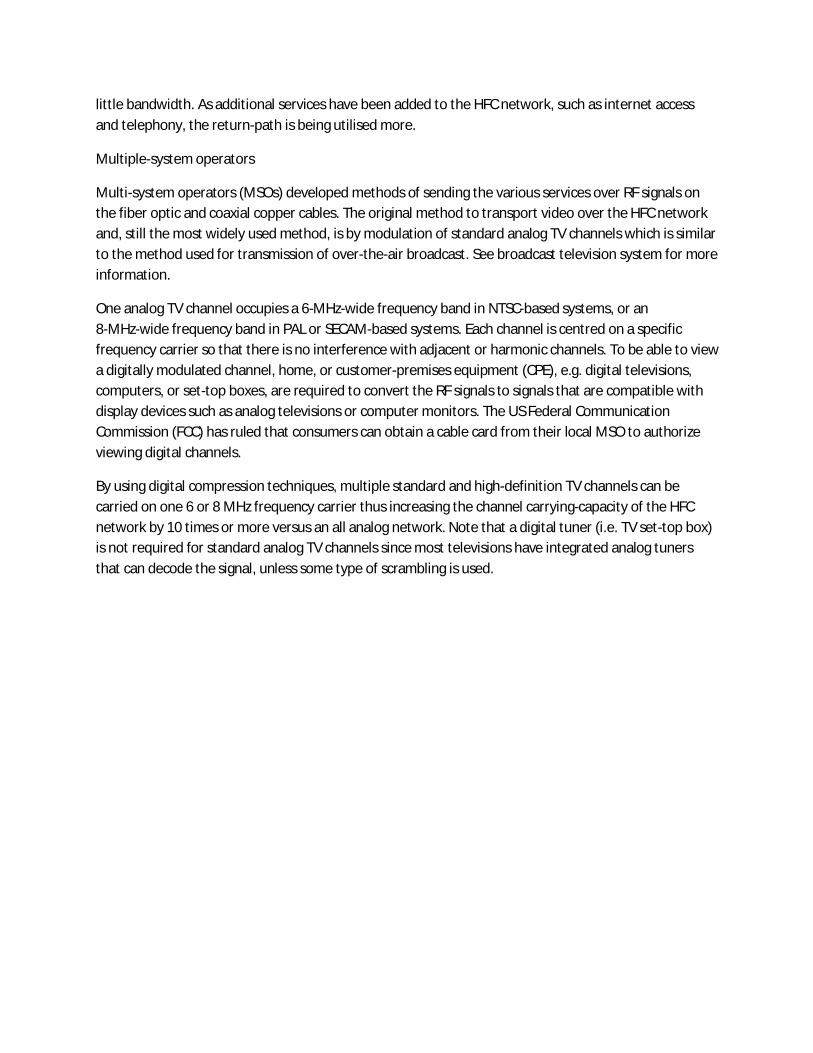
Equi pment Unit P. Con/Unit
AC 1000
AC 8000
CXE 202
CXE 101
1
7
9
0
40W
19W
14W
12.5W
350W
D_AmpAverage port/
AmpTot. Port
9 88 800
L_Amp Tot. Port
7 40 280
Average port /
Amp
HP
1350 80 1080
Penet ration HH
Opt ical Node AC8000
Output RF level 96 ÷104dbµV
220 VAC
65 VAC
SH_03 Area
REV
1. 0
NA SHEET 1 OF 1
Drawing and Verified by : EROS VEIZI
ON
L. Amplifier
D. Amplifier
D.C
Outdoor passive
Indoor Passive
Optical Cable
Optical Splitter
N115Cu & QR540
D Distr ibution
Power Supply
Power Inserter
LEGEND
RG11
Fiber Optics
10 79 dbµV 97-105 dbµV
FSCM NO DWG NO
SCALE
220 m
200 m
Reverse path aligned according to OMI/channel calculation, use
of reference pilot carrier is endorsed
T20/8 T17/8
T14/8
T14/8 T11/8
T17/8
T20/8
8
T23/8
97-105 dbµV
T20/8
T17/8 T11/8
11 79 dbµV
97-105 dbµV
T20/8 T17/8
T17/8 T11/8T23/8 T20/8
13
79 dbµV
97-105 dbµV
T20/8 T17/8
T17/8T23/8 T20/8
12
T23/8
97-105 dbµV
T14/8
T20/8 T14/8 T11/8
T11/8
T20/8 T14/8
T11/8
T14/8 T11/8
16
T23/8
97-105 dbµV
T17/8
T20/8 T17/8
15
S
3
T
2
T
4
T
4
T
4
T
4
T11/8
T14/8 T11/8
S
3
T
2
T
4
T
4
T
4
T
4
14
S
3
T
2
T
4
T
4
T
4
T
4
S
3
T
2
T
4
T
4
T
4
T
4
997-105 dbµV
T20/8 T17/8
T11/8
130 m
T20/8 T17/8 T14/8
83 dbµV 97-105 dbµV
T20/8 T17/8
T17/8T23/8 T20/4
5
T23/8
97-105 dbµV
T17/8
T20/8 T17/8 T14/8
T14/8 T11/8
T11/8
T14/8
T17/8
T20/8
T17/8 T11/8
T20/8
84 dbµV 97-105 dbµV
T20/8 T17/8
T20/8
T17/8
T23/8 T17/8
T20/8 T17/8
2
T23/8
97-105 dbµV
T20/8 T14/8 T11/8
97-105 dbµV
T20/8 T17/8
T17/8T23/8 T20/8 T11/8
T14/8 T11/8
T17/8
1
97-105 dbµV
T14/8
T17/8
T20/8 T11/8
T17/8 T14/8 T11/8
T23/8 T17/8
T20/8 T14/8 T11/8
T14/8 T11/8
7
T20/8 T14/8 T11/8
6
4
T11/4
T11/8
T14/8T23/8 T20/8 T11/8
3
120 m
1 m90 m
120 m
DC 12
100 m
140 m
1 m
180 m
100 m
1 m
170 m130 m
fully conf igured
with transponder
1 x US Tx
fully conf igured
with transponder
1 x US Tx