Shell& Tube Ht Design
8
Shell and Tube Heat Exchanger Design Software for Educational Applications* K. C. LEONG and K. C. TOH School of Mechanical and Production Engineering, Nanyang Technological University, Nanyang Avenue, Singapore 639798, Republic of Singapore. E-mail: [email protected] Y. C. LEONG Public Works Department, Ministry of National Development, 5 Maxwell Road, MND Building, Singapore 069110, Republic of Singapore A software for the thermal and hydraulic design of shell and tube heat exchangers with flow- induced vibration checks has been developed in a Windows-based Delphi programming environ- ment. Its user-friendly input format and excellent colour graphics features make it an excellent tool for the teaching, learning and preliminary design of shell and tube heat exchangers. Design methodology is based on the open literature Delaware method while flow-induced vibration calculations adhere closely to the methodology prescribed by the latest TEMA standards for industry practice. It is hoped that the software will bridge the gap between the teaching of engineering fundamentals and the existing industry practice of shell and tube heat exchanger design. INTRODUCTION SHELL AND TUBE heat exchangers are commonly used as oil coolers, power condensers, preheaters and steam generators in both fossil fuel and nuclear-based energy production applications. They are also widely used in process applications and in the air conditioning and refrigeration indus- try. Although they are not specially compact, their robustness and shape make them well suited for high pressure operations. In view of the diverse engineering applications and basic configuration of shell and tube heat exchangers, the thermal analysis and design of such exchangers form an integral part of the undergraduate mechanical and chemical engineering curricula of most universities. Senior level or final year undergraduate courses often include an elective subject for thermal design of heat exchangers. Reflecting the growing trend of using computers for design and teaching, recent heat transfer texts by Mills [1] and Incropera and DeWitt [2] incorp- orate computer software for the design and opti- mization of heat exchangers. These software are written to reinforce fundamental concepts and ideas and allow design calculations for generic configurations with no reference to design codes and standards used in the heat exchanger industry. For actual engineering applications, most shell and tube heat exchangers are designed using commer- cially available software such as those developed by co-operative research organizations such as Heat Transfer and Fluid Flow Service (HTFS) and Heat Transfer Research Inc. (HTRI) and by computer service companies such as B-JAC Inter- national. These programs offer design and cost analysis for all primary heat exchanger types and incorporate multiple design codes and standards from the American Society of Mechanical Engi- neers (ASME), Tubular Exchangers Manufac- turers Association (TEMA) and the International Standards Organisation (ISO). However, these programs are application oriented and contain company proprietary data with little pedagogical value to engineers with little or no knowledge of heat exchanger design and students in the mechan- ical and chemical engineering disciplines. This paper describes a user-friendly computer software developed for the thermal and hydraulic design of shell and tube heat exchangers based on the open literature Delaware method. The use of this soft- ware will bridge the gap between engineering practice and teaching of shell and tube heat exchanger design. DESCRIPTION OF SOFTWARE The shell and tube heat exchanger design soft- ware is developed for use in the teaching of thermal and hydraulic design of shell and tube heat exchan- gers usually at the senior undergraduate level of a mechanical or chemical engineering course. It may also be used for the preliminary design of shell and heat exchangers in actual industrial applications. Developed in Borland International’s Delphi programming environment with advanced graphics features, the Microsoft Windows-based software can be implemented on an IBM or * Accepted 5 February 1998. 217 Int. J. Engng Ed. Vol. 14, No. 3, p. 217–224, 1998 0949-149X/91 $3.00+0.00 Printed in Great Britain. # 1998 TEMPUS Publications.
-
Upload
vsraochemical1979 -
Category
Documents
-
view
2.186 -
download
4
Transcript of Shell& Tube Ht Design
Shell and Tube Heat Exchanger DesignSoftware for Educational Applications*
K. C. LEONG and K. C. TOHSchool of Mechanical and Production Engineering, Nanyang Technological University, Nanyang Avenue,Singapore 639798, Republic of Singapore. E-mail: [email protected]. C. LEONGPublic Works Department, Ministry of National Development, 5 Maxwell Road, MND Building,Singapore 069110, Republic of Singapore
A software for the thermal and hydraulic design of shell and tube heat exchangers with flow-induced vibration checks has been developed in a Windows-based Delphi programming environ-ment. Its user-friendly input format and excellent colour graphics features make it an excellent toolfor the teaching, learning and preliminary design of shell and tube heat exchangers. Designmethodology is based on the open literature Delaware method while flow-induced vibrationcalculations adhere closely to the methodology prescribed by the latest TEMA standards forindustry practice. It is hoped that the software will bridge the gap between the teaching ofengineering fundamentals and the existing industry practice of shell and tube heat exchangerdesign.
INTRODUCTION
SHELL AND TUBE heat exchangers arecommonly used as oil coolers, power condensers,preheaters and steam generators in both fossil fueland nuclear-based energy production applications.They are also widely used in process applicationsand in the air conditioning and refrigeration indus-try. Although they are not specially compact, theirrobustness and shape make them well suited forhigh pressure operations. In view of the diverseengineering applications and basic configurationof shell and tube heat exchangers, the thermalanalysis and design of such exchangers form anintegral part of the undergraduate mechanical andchemical engineering curricula of most universities.Senior level or final year undergraduate coursesoften include an elective subject for thermal designof heat exchangers.
Reflecting the growing trend of using computersfor design and teaching, recent heat transfer textsby Mills [1] and Incropera and DeWitt [2] incorp-orate computer software for the design and opti-mization of heat exchangers. These software arewritten to reinforce fundamental concepts andideas and allow design calculations for genericconfigurations with no reference to design codesand standards used in the heat exchanger industry.For actual engineering applications, most shell andtube heat exchangers are designed using commer-cially available software such as those developedby co-operative research organizations such asHeat Transfer and Fluid Flow Service (HTFS)
and Heat Transfer Research Inc. (HTRI) and bycomputer service companies such as B-JAC Inter-national. These programs offer design and costanalysis for all primary heat exchanger types andincorporate multiple design codes and standardsfrom the American Society of Mechanical Engi-neers (ASME), Tubular Exchangers Manufac-turers Association (TEMA) and the InternationalStandards Organisation (ISO). However, theseprograms are application oriented and containcompany proprietary data with little pedagogicalvalue to engineers with little or no knowledge ofheat exchanger design and students in the mechan-ical and chemical engineering disciplines. Thispaper describes a user-friendly computer softwaredeveloped for the thermal and hydraulic design ofshell and tube heat exchangers based on the openliterature Delaware method. The use of this soft-ware will bridge the gap between engineeringpractice and teaching of shell and tube heatexchanger design.
DESCRIPTION OF SOFTWARE
The shell and tube heat exchanger design soft-ware is developed for use in the teaching of thermaland hydraulic design of shell and tube heat exchan-gers usually at the senior undergraduate level of amechanical or chemical engineering course. It mayalso be used for the preliminary design of shell andheat exchangers in actual industrial applications.Developed in Borland International's Delphiprogramming environment with advancedgraphics features, the Microsoft Windows-basedsoftware can be implemented on an IBM or* Accepted 5 February 1998.
217
Int. J. Engng Ed. Vol. 14, No. 3, p. 217±224, 1998 0949-149X/91 $3.00+0.00Printed in Great Britain. # 1998 TEMPUS Publications.
compatible personal computer with at least a80386 microprocessor, 4 MB of RAM and atleast 5 MB of free hard disk space.
Components of the softwareThe software consists of four modules viz.
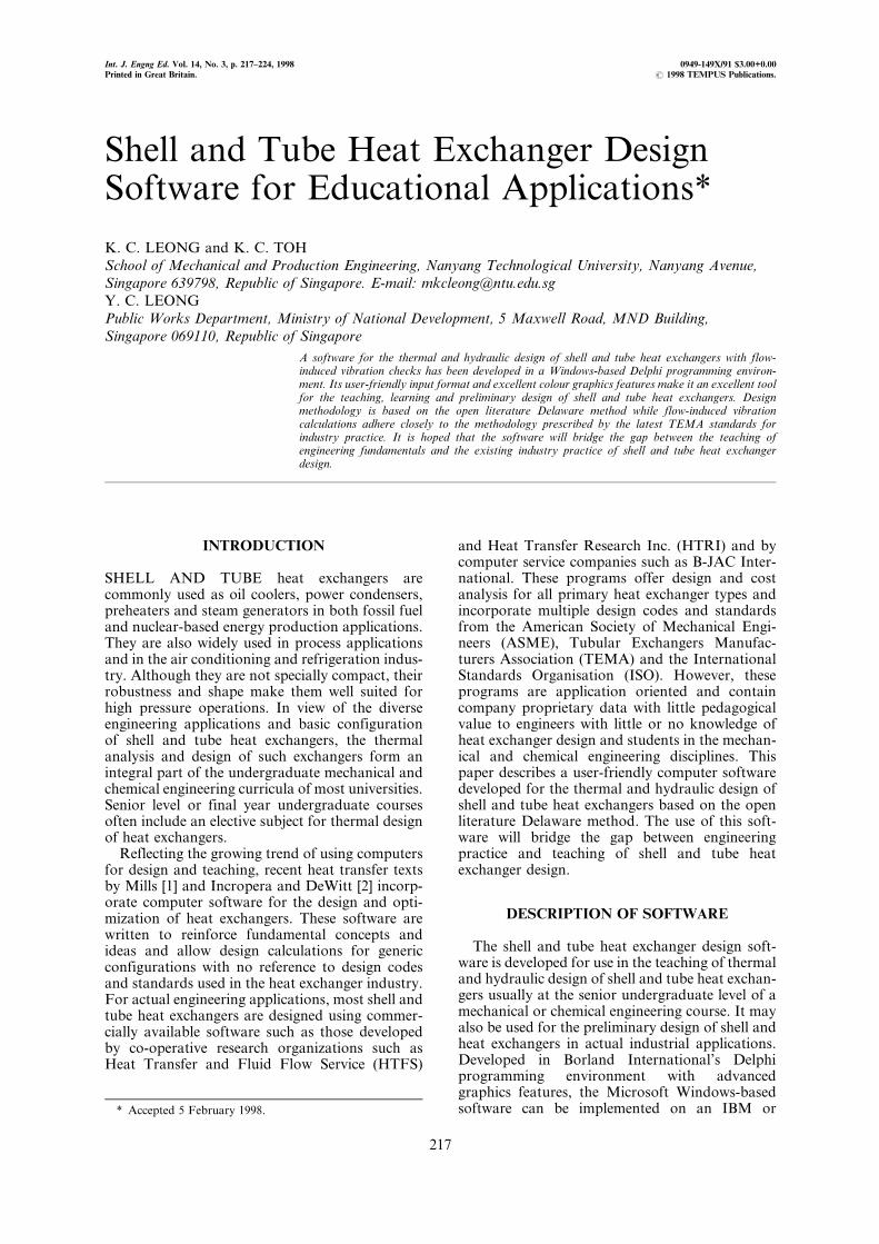
Sizing, Rating, Vibration and Tutorial. TheSizing module allows the size of a shell and tubeheat exchanger to be determined based on inputsof fluids temperatures, flowrates and pressure dropand dimensional constraints. The user can call outa graphics screen showing the different physicalconfigurations of shell and tube heat exchangersbased on the Standards of the Tubular ExchangerManufacturers Association (TEMA) [3]. Thermo-physical properties of common fluids are includedin the software and are automatically calculatedbased on input fluid temperatures. The existingdatabase of fluid properties cater for water, air,Freon-12, ethylene glycol, glycerine and mercury.The module allows for user input of thermo-physical properties of fluids not found in thedatabase. Figure 1 shows the user-friendly menu-driven input format which accepts either SI,Imperial or a combination of both units. TheImperial units option is built into the software inrecognition of the fact that a large number of heatexchangers are designed, constructed and used inthe United States. Design results can be presentedin graphics showing a labelled and dimensionedheat exchanger. This feature enables the student ornew engineer to quickly visualize the key construc-tional features of a shell and tube heat exchangersand its relative dimensions.
The Rating module allows the user to calculatewhether a selected exchanger can meet the requiredthermal and hydraulic duty. User inputs of geome-trical dimensions of the heat exchanger to be ratedis required.
Fluid flow, inter-related with heat exchangergeometry, can cause heat exchanger tubes tovibrate and cause possible damage to theexchanger. The Vibration module developedbased on the methodology outlined in the 1988edition of TEMA standards [4] allows the user tocheck the extent of flow-induced vibration afteran exchanger is sized. To the best of the authors'knowledge, existing commercial flow-inducedvibration software are offered separately fromthermal and hydraulic design software. The inte-gration of the Vibration module in this shell andheat exchanger design software allows the user toconveniently conduct flow induced vibrationchecks on his design.
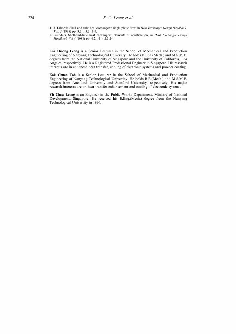
The Tutorial module is a self-learning tool forthe student and novice engineer. It introduces thebasic construction of a shell and tube heat exchan-ger, exchanger selection and instructions on how touse the various software modules.
Two other features set this software apart frommost software developed for educational appli-cations. Firstly, calculated dimensions of the heatexchanger can be saved into a text file which can beconveniently incorporated into all commerciallyavailable word processing software. This featureis useful for the generation of design reports.Secondly, detailed calculation steps are alsoavailable to facilitate the understanding ofconcepts used in the design. This feature sets thissoftware apart from most commercial packageswhich behave like `black boxes' and have nopedagogical use.
Choice of programming environment and languageThe use of conventional programming languages
such as FORTRAN suffers from the disadvantageof poor graphical presentation. To develop a user-friendly software, the authors have decided to use
Fig. 1. Input format for sizing module.
K. C. Leong et al.218
Borland's latest programming environment,Delphi which is completely object-oriented.Delphi's programming language is Object Pascaland allows the software to be developed in acompletely visual environment with the sourcecode constantly being updated. The result is user-friendly input formats and excellent graphicswhich facilitates computer-aided learning.
Shell-side heat transferAs most commercial programs are based on
company-proprietary data, it is not possible toadapt these programs for engineering education.The authors have therefore chosen an open litera-ture method called the Delaware Method firstproposed by Bell in 1963 [4, 5]. The Delawaremethod is a rating method. Rating an exchangermeans to evaluate the thermohydraulic perfor-mance of a fully specified exchanger. The resultof a rating process is a judgement as to the abilityof the unit to perform a desired duty and complywith other design conditions of operation such asgood pressure drop utilization, cleaning, thermalexpansion, safety, and tube vibration.
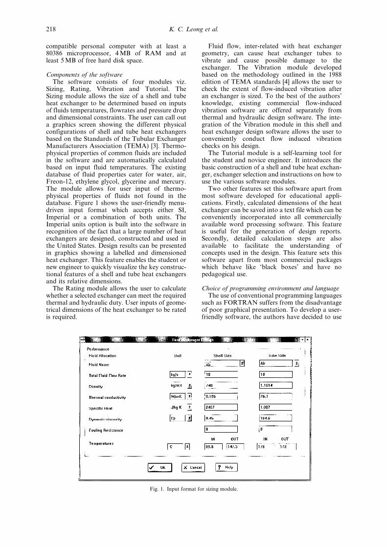
For a baffled shell-side flow, the analysis is socomplex that it cannot be adequately expressed ona generalized basis by a simple approach such asthe effectiveness-number of transfer units correla-tion. Only part of the fluid takes the desired paththrough the tube nest, whereas a potentiallysubstantial portion flows through the `leakage'area (baffle-to-shell and tube-to-baffle) and the`bypass' area between tube bundle and the shellwall. However, these clearances are inherent to themanufacturing and assembly process of shell-and-tube exchangers, and the flow distribution withinthe exchanger must be taken into account. In theDelaware method, the fluid flow in the shell asillustrated in Fig. 2 is divided into a number ofindividual streams as follows:
1. Stream A is the leakage stream in the orificeformed by the clearance between the baffle tubehole and the tube wall.
2. Stream B is the main effective cross-flow
stream, which can be related to flow acrossideal tube banks.
3. Stream C is the tube bundle bypass stream inthe gap between the bundle and the shell wall.
4. Stream E is the leakage stream between thebaffle edge and the shell wall.
5. Stream F is the bypass stream in flow chan-nels due to omission of tubes in tube passpartitions.
Each of the above streams introduces a cor-rection factor to the heat transfer correlation forideal cross-flow across a bank of tubes. Thebasic equation for calculating the effective aver-age shell-side heat transfer coefficient h is givenas:
h � hideal Jc Jl Jb Js Jr �1�where hideal � heat transfer coefficient for pure
cross-flow in an ideal tube bank,Jc � correction factor for baffle cut and
spacing,Jl � correction factor for baffle leakage
effects,Jb � correction factor for bundle bypass
flow (C and F streams),Js � correction factor for variable baffle
spacing in the inlet and outletsections, and
Jr � correction factor for adversetemperature gradient build-up.
The combined effect of all of these correctionfactors for a well-designed shell-and-tube heatexchanger is typically of the order of 0.6; that is,the effective mean shell-side heat transfer coeffi-cient for the exchanger is 60% of that calculated ifthe entire flow took place across an ideal tube bankcorresponding in geometry to one cross-flowsection. It is interesting to observe that this valuehas long been used as a rule of thumb.
Shell-side pressure dropShell-side pressure drop is built up in the
Delaware method by summing the pressure drops
Fig. 2. Shell-side flow streams.
Shell and Tube Heat Exchanger Design Software 219
for the inlet and exit sections. The total pressuredrop over the exchanger is given by:
�ptot � �pc ��pw ��pe �2�where �pc � pressure drop in the interior cross-
flow sections from baffle tip to baffletip,
�pw � pressure drop in the windowsections, and
�pe � pressure drop in the entrance andexit sections.
This does not include the pressure drop in thenozzles, which is usually included in the specifi-cation. Each of the above pressure drop terms hascorrection factors analogous to those for heattransfer. A detailed description in given in Ref. [4].
The total shell-side pressure drop of a typicalshell and tube exchanger is of the order of 20% to30% of the pressure drop that would be calculatedfor flow through the corresponding heat exchangerwithout baffle leakage and without tube bundlebypass effects.
Flow-induced vibrationFluid flow, interrelated with heat exchanger
geometry, can cause heat exchanger tubes to
vibrate. This phenomenon is highly complex andthe present state-of-the-art is such that the solutionto this problem is difficult to define. Hence, afteran exchanger is designed, it is necessary to checkfor any flow-induced vibration which may causedamage to the exchanger. The methodologyadopted in the Vibration module of this softwarefollows closely the prescribed formulae in the1988 edition of the TEMA standards [3] forcalculating the natural frequency of a tube, criticalflow velocity for a tube span, acoustic frequency,vortex shedding frequency and turbulent buffetingfrequency. The calculations for this module areperformed in Imperial units and the resultsconverted to SI units.
SOFTWARE UTILIZATION IN DESIGNEDUCATION
The software is suitable for teaching thermaland hydraulic design of shell and tube heatexchangers to senior undergraduate students inmechanical and chemical engineering and also totrain new graduate engineers in thermal design.Students may be asked to use the software toundertake a few mini projects in shell and tubeheat exchanger design. The following exampleillustrates how the software can be used in such amanner.
ExampleUse the computer program to design a shell and
tube heat exchanger based on the informationgiven in Table 1. Perform a flow-induced vibrationcheck on the designed exchanger. Take the shell-side fluid to be air and the tube-side fluid to bewater.
Depending on the limitations imposed on theshell size, there can numerous design solutions.For the sake of brevity, only four solutions are
Table 1. Design information
Description Quantity
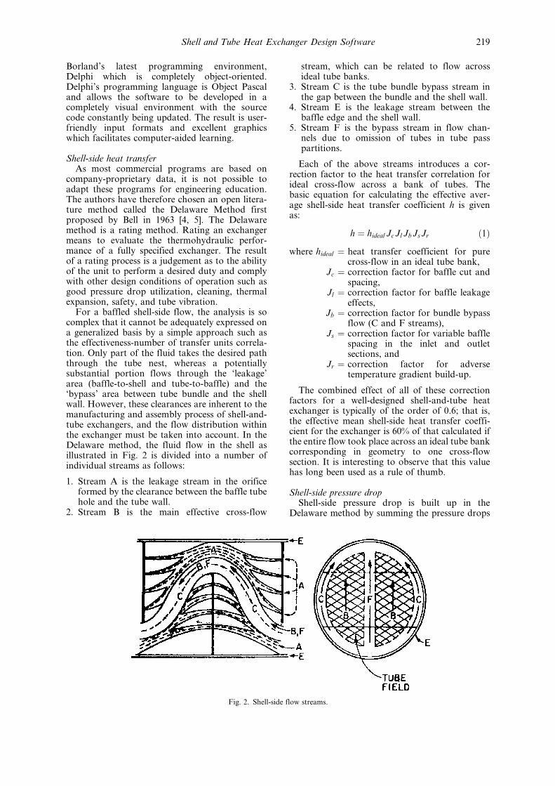
Flow rate for shell-side fluid 1.689 kg/sFlow rate for tube-side fluid 10 kg/sFouling factor in shell 0.0001Fouling factor in tubes 0.000 175Temperature in (shell-side fluid) 1008CTemperature out (shell-side fluid) 408CTemperature in (tube-side fluid) 308CTemperature out (tube-side fluid) 36.18CMaximum allowable shell diameter 1000 mmMaximum allowable shell-side pressure drop 4.8 kPaTEMA configuration AET
Table 2. Some design solutions
Solution 1 2 3 4Shell internal diameter (mm) 838 889 889 940Layout pitch (mm) 31.75 31.75 39.69 36.69Tube length (mm) 2095 1955.8 2578.1 2397Baffle spacing (mm) 335.2 311.150 355.6 329Tube outer diameter (mm) 25.4 25.4 31.75 31.75Tube layout angle (degrees) 90 90 90 90Number of tubes 439 497 316 355Number of sealing strips (pair) 1 1 1 1Baffle cut (%) 24.5 23.375 24.5 23.375Number of baffles 3 3 4 4Actual heat duty (kW) 260 305.8 258 447.9 278 526.5 275 955.1Required heat duty (kW) 257 403.6 257 403.6 257 403.6 257 403.6Pressure drop shell side (kPa) 4.43724 4.61526 4.10141 4.24115Number of tube passes 2 2 2 2Critical velocity (m/s) 98.88 87.22 147.18 184.86Cross-flow velocity (m/s) 32.53 29.61 29.74 31.71Vortex shedding frequency (Hz) 538.05 489.70 393.47 419.50Natural frequency (Hz) 145.48 130.13 163.14 199.78Turbulent buffeting frequency (Hz) 329.52 299.90 241.03 257.00Acoustic frequency (Hz) 117.63 111.25 111.25 105.53
K. C. Leong et al.220

shown in Table 2. All solutions are based on singlesegmental baffle design.
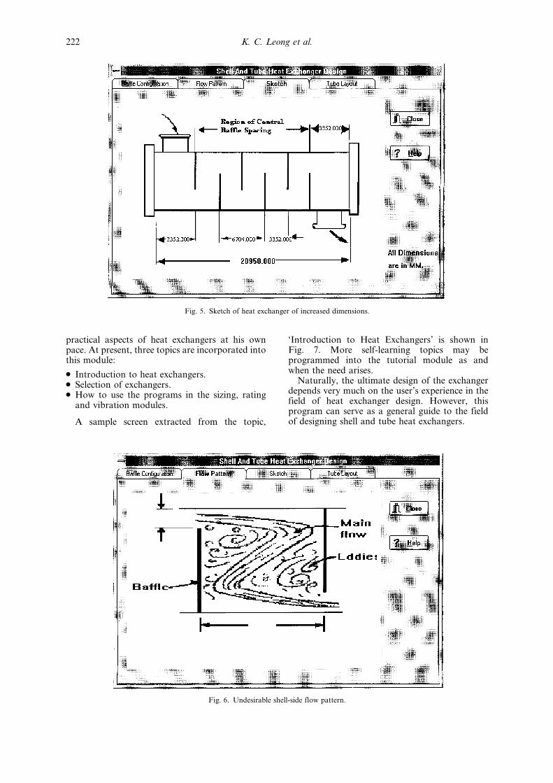
The program gives a choice of various graphicsdepicting the baffle configuration, flow pattern,sketch of heat exchanger and tube layout of eachchosen solution. Figure 3 shows a sketch of thedimensioned exchanger corresponding to solution1 while Fig. 4 shows its shell-side fluid flow pattern.Consider the case in which the tube length and bafflespacing are changed to 20 950 mm and 3352 mm,respectively. The program can then be used to
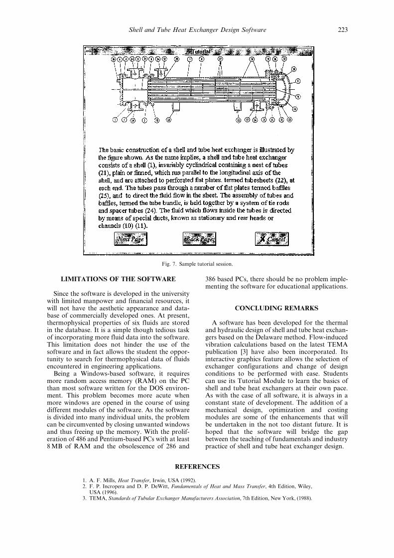
quickly re-evaluate the solution and the corre-sponding sketch and shell-side fluid flow patternare shown in Figs 5 and 6, respectively. From Fig.6, it can be seen that the shell-side flow pattern isnot ideal and solution can then be rejected.
TutorialThe tutorial module in the software supplements
classroom teaching of the basics of a shell andtube heat exchanger. It allows the student and thenew engineer to review some of the concepts and
Fig. 3. Sketch of heat exchanger corresponding to solution 1.
Fig. 4. Shell-side flow pattern for solution 1.
Shell and Tube Heat Exchanger Design Software 221
practical aspects of heat exchangers at his ownpace. At present, three topics are incorporated intothis module:
. Introduction to heat exchangers.
. Selection of exchangers.
. How to use the programs in the sizing, ratingand vibration modules.
A sample screen extracted from the topic,
`Introduction to Heat Exchangers' is shown inFig. 7. More self-learning topics may beprogrammed into the tutorial module as andwhen the need arises.
Naturally, the ultimate design of the exchangerdepends very much on the user's experience in thefield of heat exchanger design. However, thisprogram can serve as a general guide to the fieldof designing shell and tube heat exchangers.
Fig. 5. Sketch of heat exchanger of increased dimensions.
Fig. 6. Undesirable shell-side flow pattern.
K. C. Leong et al.222
LIMITATIONS OF THE SOFTWARE
Since the software is developed in the universitywith limited manpower and financial resources, itwill not have the aesthetic appearance and data-base of commercially developed ones. At present,thermophysical properties of six fluids are storedin the database. It is a simple though tedious taskof incorporating more fluid data into the software.This limitation does not hinder the use of thesoftware and in fact allows the student the oppor-tunity to search for thermophysical data of fluidsencountered in engineering applications.
Being a Windows-based software, it requiresmore random access memory (RAM) on the PCthan most software written for the DOS environ-ment. This problem becomes more acute whenmore windows are opened in the course of usingdifferent modules of the software. As the softwareis divided into many individual units, the problemcan be circumvented by closing unwanted windowsand thus freeing up the memory. With the prolif-eration of 486 and Pentium-based PCs with at least8 MB of RAM and the obsolescence of 286 and
386 based PCs, there should be no problem imple-menting the software for educational applications.
CONCLUDING REMARKS
A software has been developed for the thermaland hydraulic design of shell and tube heat exchan-gers based on the Delaware method. Flow-inducedvibration calculations based on the latest TEMApublication [3] have also been incorporated. Itsinteractive graphics feature allows the selection ofexchanger configurations and change of designconditions to be performed with ease. Studentscan use its Tutorial Module to learn the basics ofshell and tube heat exchangers at their own pace.As with the case of all software, it is always in aconstant state of development. The addition of amechanical design, optimization and costingmodules are some of the enhancements that willbe undertaken in the not too distant future. It ishoped that the software will bridge the gapbetween the teaching of fundamentals and industrypractice of shell and tube heat exchanger design.
REFERENCES
1. A. F. Mills, Heat Transfer, Irwin, USA (1992).2. F. P. Incropera and D. P. DeWitt, Fundamentals of Heat and Mass Transfer, 4th Edition, Wiley,
USA (1996).3. TEMA, Standards of Tubular Exchanger Manufacturers Association, 7th Edition, New York, (1988).
Fig. 7. Sample tutorial session.
Shell and Tube Heat Exchanger Design Software 223
4. J. Taborek, Shell-and-tube heat exchangers: single-phase flow, in Heat Exchanger Design Handbook,Vol. 3 (1988) pp. 3.3.1±3.3.11-5.
5. Saunders, Shell-and-tube heat exchangers: elements of construction, in Heat Exchanger DesignHandbook Vol 4 (1988) pp. 4.2.1-1±4.2.5-24.
Kai Choong Leong is a Senior Lecturer in the School of Mechanical and ProductionEngineering of Nanyang Technological University. He holds B.Eng.(Mech.) and M.S.M.E.degrees from the National University of Singapore and the University of California, LosAngeles, respectively. He is a Registered Professional Engineer in Singapore. His researchinterests are in enhanced heat transfer, cooling of electronic systems and powder coating.
Kok Chuan Toh is a Senior Lecturer in the School of Mechanical and ProductionEngineering of Nanyang Technological University. He holds B.E.(Mech.) and M.S.M.E.degrees from Auckland University and Stanford University, respectively. His majorresearch interests are on heat transfer enhancement and cooling of electronic systems.
Yit Chaw Leong is an Engineer in the Public Works Department, Ministry of NationalDevelopment, Singapore. He received his B.Eng.(Mech.) degree from the NanyangTechnological University in 1996.
K. C. Leong et al.224