Shear Strength Concrete Structures
18
Concrete Plasticity and its Application. University of Cambridge 23 rd July, 2007 1 AN ADEQUATE THEORY FOR THE SHEAR STRENGTH OF REINFORCED CONCRETE STRUCTURES Michael P. COLLINS 1 Evan C. BENTZ 1 Edward G. SHERWOOD 1 Liping XIE 1 1 Department of Civil Engineering, University of Toronto, Toronto, Ontario, Canada Keywords: concrete, shear, plasticity, size effect, strut-and-tie, safety. 1 INTRODUCTION In a 1935 Engineering News Record review article [1] for structural design engineers, Professor Hardy Cross quoted with approval the paradoxical statement of the Cambridge astrophysicist Sir Arthur Eddington that “No experiment is worthy of credence unless supported by an adequate theory.” For complex phenomena influenced by many variables understanding the meaning of particular experiments and the range of applicability of the results is extremely difficult unless the researcher is guided by an adequate theory which can identify the important parameters. Such a theory, based on Hooke’s observation in 1678 that plane sections remain plane [2], is universally used in determining the flexural strength of reinforced concrete members. Developing a comparable theory for the shear strength of reinforced concrete members has been the objective of a major worldwide research effort for more than 40 years. For members with significant amounts of shear reinforcement, a variable angle truss model based on the lower bound theory of plasticity has been developed and is incorporated into Eurocode 2 [3]. However for the potentially more dangerous cases of members without shear reinforcement Eurocode 2 uses totally empirical procedures not “supported by an adequate theory”. This paper will introduce a simple general theory for predicting the shear strength of reinforced and prestressed concrete members either with or without shear reinforcement. The theory, which has been developed at the University of Toronto over the last 35 years, includes both a strut- and-tie model for disturbed regions and a sectional model for regions where plane sections remain plane. The distinguishing feature of these models is that in addition to the equilibrium conditions used by plasticity, consideration is given to the compatibility of concrete strains and reinforcement strains. The theory forms the basis of the shear design provisions of the 2004 edition of the Canadian Standards Association (CSA) “Design of Concrete Structures” [4]. While giving the keynote address on “Shear and Torsion” at the 1970 FIP Congress Professor Fritz Leonhardt suggested that one of the prime reasons for the poor quality of design provisions was that shear and torsional strengths were influenced by about 20 variables and that so many of the available experimental results were either impractical or of poor quality. He proposed that to understand the influence of just one variable, five reasonably large-scale tests in which only this one variable is changed should be conducted. In this paper a number of such experimental series will be examined and the observed influence of changing the various parameters will be compared to the predictions made by three current design codes for concrete structures, the Eurocode, EC2, the American Concrete Institute 2005 [5] code, ACI, and the Canadian Standards Association code, CSA. 2 DEVELOPMENT OF US AND EUROPEAN SHEAR DESIGN PROVISIONS While flexural design is concerned with ensuring that the two sides of a member can resist the appropriate magnitudes of tensile or compressive longitudinal forces, shear design is intended to ensure that the two sides of the member continue to act as a unit. This involves identifying where shear reinforcement is required to link together the two sides of the member and determining how much of this reinforcement is needed to prevent a premature shear failure. For regions not containing shear reinforcement, a shear failure can occur without warning and typically involves the opening of a major diagonal crack such as those shown in Fig. 1. Traditional American shear design procedures assumed that such failures of members without shear reinforcement would not occur if the calculated shear stress, V/(b w jd), at service loads was less than about 0.03f c ’. If the shear stress was higher than this allowable stress, then shear reinforcement (e.g. links) would be added to carry the excess. The capacity added by the links was given by the 45º truss model of Ritter and Mörsch as ρ w f s where f s was the allowable tensile stress in the links. Such shear reinforcement controls the opening of diagonal cracks and permits much higher shear stresses to be resisted. Irrespective of the amount of links, however, an upper limit of 0.12f c ’ was placed on the shear stress at service load. In traditional
-
Upload
mmendez113 -
Category
Documents
-
view
30 -
download
2
description
Experimental research on shear strength of concrete structures from the University of Cambridge
Transcript of Shear Strength Concrete Structures
Concrete Plasticity and its Application. University of Cambridge 23rd July, 2007
1
AN ADEQUATE THEORY FOR THE SHEAR STRENGTH OF
REINFORCED CONCRETE STRUCTURES
Michael P. COLLINS 1 Evan C. BENTZ 1 Edward G. SHERWOOD 1 Liping XIE 1
1 Department of Civil Engineering, University of Toronto, Toronto, Ontario, Canada Keywords: concrete, shear, plasticity, size effect, strut-and-tie, safety. 1 INTRODUCTION
In a 1935 Engineering News Record review article [1] for structural design engineers, Professor Hardy Cross quoted with approval the paradoxical statement of the Cambridge astrophysicist Sir Arthur Eddington that “No experiment is worthy of credence unless supported by an adequate theory.” For complex phenomena influenced by many variables understanding the meaning of particular experiments and the range of applicability of the results is extremely difficult unless the researcher is guided by an adequate theory which can identify the important parameters. Such a theory, based on Hooke’s observation in 1678 that plane sections remain plane [2], is universally used in determining the flexural strength of reinforced concrete members. Developing a comparable theory for the shear strength of reinforced concrete members has been the objective of a major worldwide research effort for more than 40 years. For members with significant amounts of shear reinforcement, a variable angle truss model based on the lower bound theory of plasticity has been developed and is incorporated into Eurocode 2 [3]. However for the potentially more dangerous cases of members without shear reinforcement Eurocode 2 uses totally empirical procedures not “supported by an adequate theory”. This paper will introduce a simple general theory for predicting the shear strength of reinforced and prestressed concrete members either with or without shear reinforcement. The theory, which has been developed at the University of Toronto over the last 35 years, includes both a strut-and-tie model for disturbed regions and a sectional model for regions where plane sections remain plane. The distinguishing feature of these models is that in addition to the equilibrium conditions used by plasticity, consideration is given to the compatibility of concrete strains and reinforcement strains. The theory forms the basis of the shear design provisions of the 2004 edition of the Canadian Standards Association (CSA) “Design of Concrete Structures” [4].
While giving the keynote address on “Shear and Torsion” at the 1970 FIP Congress Professor Fritz Leonhardt suggested that one of the prime reasons for the poor quality of design provisions was that shear and torsional strengths were influenced by about 20 variables and that so many of the available experimental results were either impractical or of poor quality. He proposed that to understand the influence of just one variable, five reasonably large-scale tests in which only this one variable is changed should be conducted. In this paper a number of such experimental series will be examined and the observed influence of changing the various parameters will be compared to the predictions made by three current design codes for concrete structures, the Eurocode, EC2, the American Concrete Institute 2005 [5] code, ACI, and the Canadian Standards Association code, CSA. 2 DEVELOPMENT OF US AND EUROPEAN SHEAR DESIGN PROVISIONS
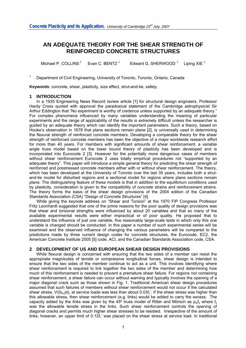
While flexural design is concerned with ensuring that the two sides of a member can resist the appropriate magnitudes of tensile or compressive longitudinal forces, shear design is intended to ensure that the two sides of the member continue to act as a unit. This involves identifying where shear reinforcement is required to link together the two sides of the member and determining how much of this reinforcement is needed to prevent a premature shear failure. For regions not containing shear reinforcement, a shear failure can occur without warning and typically involves the opening of a major diagonal crack such as those shown in Fig. 1. Traditional American shear design procedures assumed that such failures of members without shear reinforcement would not occur if the calculated shear stress, V/(bw jd), at service loads was less than about 0.03fc’. If the shear stress was higher than this allowable stress, then shear reinforcement (e.g. links) would be added to carry the excess. The capacity added by the links was given by the 45º truss model of Ritter and Mörsch as ρwfs where fs was the allowable tensile stress in the links. Such shear reinforcement controls the opening of diagonal cracks and permits much higher shear stresses to be resisted. Irrespective of the amount of links, however, an upper limit of 0.12fc’ was placed on the shear stress at service load. In traditional
Concrete Plasticity and its Application. University of Cambridge 23rd July, 2007
German shear design, by contrast, once the shear stress at service load exceeded about 0.4 MPa, shear reinforcement was provided to carry the entire shear using the 45º truss model. Because of these differences in shear design requirements, American reinforced concrete beams typically contained much less shear reinforcement than comparable German beams.
Fig. 1: Shear Failure of Air Force Warehouse Beams
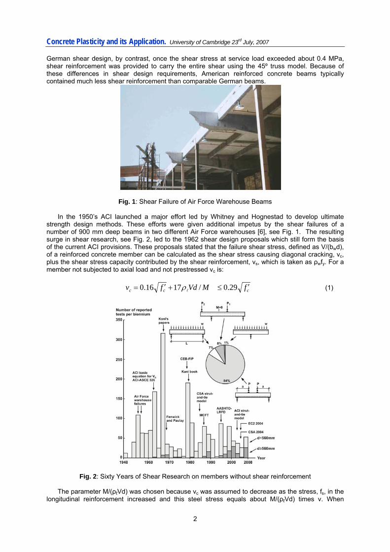
In the 1950’s ACI launched a major effort led by Whitney and Hognestad to develop ultimate strength design methods. These efforts were given additional impetus by the shear failures of a number of 900 mm deep beams in two different Air Force warehouses [6], see Fig. 1. The resulting surge in shear research, see Fig. 2, led to the 1962 shear design proposals which still form the basis of the current ACI provisions. These proposals stated that the failure shear stress, defined as V/(bwd), of a reinforced concrete member can be calculated as the shear stress causing diagonal cracking, vc, plus the shear stress capacity contributed by the shear reinforcement, vs, which is taken as ρwfy. For a member not subjected to axial load and not prestressed vc is: ccc fMVdfv ′≤+′= 29.0/1716.0 lρ (1)
Fig. 2: Sixty Years of Shear Research on members without shear reinforcement
The parameter M/(ρℓVd) was chosen because vc was assumed to decrease as the stress, fs, in the longitudinal reinforcement increased and this steel stress equals about M/(ρℓVd) times v. When
2

Concrete Plasticity and its Application. University of Cambridge 23rd July, 2007
applying this equation to high strength concrete the term √fc’ is now limited to 8.3 MPa. In a discussion to the 1962 report Johannes Moe suggested [7] a physical explanation as to why the failure shear stress of members without shear reinforcement will decrease as fs increases. He pointed out that higher steel stresses will result in wider cracks and these wide cracks will be less capable of transmitting the shear stresses required to maintain beam action and in consequence diagonal cracks will occur at lower shear stresses. This reduction in failure shear stress with increasing strain in the longitudinal reinforcement can be referred to as the strain effect in shear. During the 1960’s, Leonhardt [8] and Kani [9] both demonstrated experimentally that members such as slabs without shear reinforcement fail at lower shear stresses as the absolute member depth increases. This has become known as the size effect in shear. While he did not note it at the time, Moe’s physical explanation for the strain effect also predicts the size effect if one further assumes that larger members have more widely spaced cracks. In 1968, Fennwick and Paulay’s pioneering work on the mechanisms of shear resistance [10] confirmed Moe’s hypothesis that the majority of shear is carried by aggregate interlock stresses for members without shear reinforcement.
Since the ACI shear provisions were completed in 1962, a large number of empirical equations have been developed which attempt to provide an accurate statistical fit to the experimental data available at the time the particular equation was developed. One such equation was developed by Zsutty [11] in 1968 and proposed that the failure shear stress of members without shear reinforcement be taken as a function of (ρℓfc’)1/3. Adding a term to approximate the size effect, which reduces the failure shear stress of very deep members by a factor of about 1.6 from that of shallow-depth members, and a term to take account of the influence of axial force N (positive for compression), gives the basic 2004 EC2 expression for the shear resistance of members without shear reinforcement, which is:
( ) cck ANfd
v /15.0100200118.0 3/1 +⎟⎟⎠
⎞⎜⎜⎝
⎛+= lρ but (2a)
cck ANfd
v /15.02001035.02/3
+⎟⎟⎠
⎞⎜⎜⎝
⎛+≥ (2b)
To calculate the shear strength of members with shear reinforcement the 2004 EC2 code specifies
the use of a variable angle truss model with no contribution from concrete tensile stresses. Thus the failure shear stress, V/(bwd), of members with shear reinforcement perpendicular to the longitudinal axis of the member is given as:
θρ cot9.0 yw fv = (3)
( ) )cot/(tan9.0250/16.0 θθ +−≤ ckck ffv (4) where cotθ has a maximum value of 2.5 and a minimum value of 1. While the variable angle truss model is logical, the limits on cotθ seem rather arbitrary. As an example, the 1978 CEB-FIP model code [12], which formed the basis of the original EC2 provisions, limited the value of cotθ to within a range of 1.67 to 0.6.
EC2 requires that a minimum quantity of shear reinforcement be provided in beams such that ρwfy is at least equal to 0.08√fck, however this minimum shear reinforcement is not required for members such as slabs. Slabs, walls and footings, such as those shown in Fig. 3, have traditionally been constructed without shear reinforcement and hence the safety of such important members depends upon the accuracy of the code expressions such as Eq.(1) or Eq.(2). It does not help that these equations are typically based on experimental data which is not very representative of the practical situations shown in Fig. 3. Thus only 144 of the 1849 shear tests summarized in Fig.2 had depths greater than 560 mm and most of these large tests have been conducted after the empirical design equations were formulated. Further changes in construction practice such as the use of self-consolidating concrete made with small aggregate and the use of higher strengths of reinforcement and higher strengths of concrete require re-examination of empirical shear design procedures developed to fit data from members with quite different characteristics. All of this emphasizes the need for an adequate theoretical basis for shear design provisions.
3

Concrete Plasticity and its Application. University of Cambridge 23rd July, 2007
Fig. 3: Examples of Shear Critical Members 3 MECHANISMS OF SHEAR RESISTANCE
In carrying shear, Fennwick and Paulay [10] explained that there are two primary ways that shear can be carried in a reinforced or prestressed concrete member. Flexural tension and compression forces separated by the flexural lever arm resist bending moments. Since shear in a beam is equal to the derivative of the moment, it becomes possible to use the product rule of calculus to better understand shear. In particular, the derivative of moment will be made up of two terms: a) variation in flexural forces acting over a constant lever arm, and b) constant flexural forces acting over a variable lever arm. The former can be called “beam action” as this type of shear resistance is associated with plane sections remaining plane. The second method is sometimes called arch action or strut-and-tie action and is generally associated with diagonal compression struts in the web tied by the flexural tension reinforcement. As strut-and-tie action is geometrically incompatible with beam action and since uncracked concrete obeys the plane sections rule, beam action precedes strut-and-tie action, and it must break down before strut action can control shear strengths. Both of these shear resisting mechanisms are discussed below.
Consider the flexurally cracked beam not containing shear reinforcement shown in Fig. 4 and resisting shear by beam action. The depth of the flexural compression zone is kd and the flexural lever arm is jd. Because the compressive stresses under the loading plate fan out into the beam, the tensile force in the longitudinal reinforcement will remain about constant over a region about 2d long. Near the bottom face of the beam the spacing of the vertical cracks will be controlled by the bond characteristics of the reinforcement. Near mid-depth of the beam, crack spacing will be controlled by the distance required for tensile stresses in the concrete to spread out from the reinforcement or from the stiff uncracked compression zone. Assuming that the dispersion angle is 45º, see Fig.4, the horizontal spacing of the cracks in the upper region of the web will be about (1-k)d. Consider the free body diagram of the “tooth” of concrete defined by the neutral axis and two of these widely spaced cracks shown on the bottom left of Fig. 4 and labelled Case 1. Horizontal equilibrium requires that the average shear stress on the top horizontal plane is V/(bjd). If the vertical cracks are narrow enough to be able to transmit this shear stress by aggregate interlock, then the concrete in the tooth between the two vertical cracks will be in pure shear. This means the principal tensile stress is also equal to V/(bjd) which will cause a diagonal crack at an angle of 45º when V/(bjd) equals the cracking stress of the concrete, fcr. The ACI value for the principal tensile stress to cause diagonal cracking is 0.33√fc’
4

Concrete Plasticity and its Application. University of Cambridge 23rd July, 2007
Fig. 4: Development of Cracks When Shear is Carried by “Beam Action”
Case 2 in Fig. 4 shows the situation for a beam where the cracks are so wide that no shear stresses can be transmitted across the cracks. Again horizontal equilibrium requires that the average shear stress on any horizontal plane across the tooth must equal V/(bjd) but now these horizontal shear stresses must reduce to zero at the crack locations. In this case in order to change the force in the longitudinal reinforcement as required by beam action, bending moments causing vertical stresses must develop in the concrete tooth. The highest tensile stress in concrete tooth will occur at the top right corner and will equal 6V/(bjd). Thus, for case 2, the concrete must resist a tensile stress 6 times higher than that for case 1. In case 2, a nearly horizontal inclined crack is predicted to form when the shear stress V/(bjd) equals 0.055√fc’. Thus in terms of shear stresses expressed as V/(bd) and assuming that jd is about 0.9d, diagonal cracks are predicted to occur somewhere between 0.05√fc’ and 0.3√fc’ depending upon the width of the cracks. While the upper limit is in close agreement with the 0.29√fc’ maximum shear stress limit of the ACI equation, the value for the lower limit implies that Eq.(1) may be seriously unconservative for beams with wide cracks.
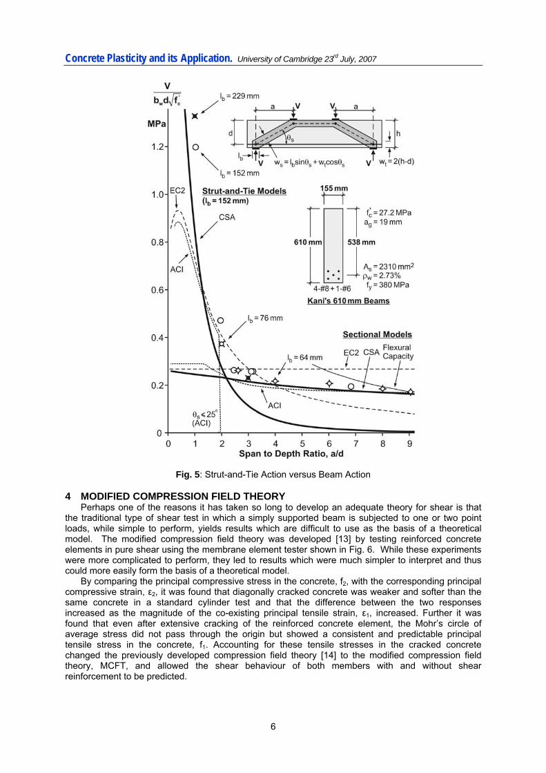
After beam action breaks down, it is possible that the strut-and-tie mechanism can carry even higher loads provided that the distance from the load to the support is not too great. This point is illustrated in Fig. 5 which shows the results of 14 of Kani’s experiments [9] where the only significant variables were the shear span to depth ratio, a/d, and the size of the bearing plates, ℓb. It is of interest that the bearing plate size had no influence on the failure load of the longer specimens but had a strong influence on the failure load of the shorter specimens. The strut-and-tie model used to determine the load carrying capacity after breakdown of beam action is shown on the figure. Strut-and-tie provisions were introduced in the 1984 edition of the CSA code and similar provisions now appear in EC2 and ACI. The predictions from these three codes are also shown on the figure. These strut-and-tie provisions differ principally in the definition of the limiting compressive stress in the diagonal strut. For EC2 and ACI, this limiting compressive stress is a function only of the concrete strength though ACI also places a lower limit of 25º on the angle, θs, between the strut and the reinforcement. For CSA, the limiting stress is a function of the angle θs and the strain in the reinforcement that crosses the strut. It should be noted that the predicted shear strength for any given a/d ratio, is taken as the larger of the beam action strength or the strut-and-tie strength. For these particular beams, it might be noted that the shear capacities of the longer beams which are governed by breakdown of beam action are more accurately predicted by the ACI and CSA provisions than by EC2. For the shorter spans, the rate of reduction in shear capacity as the shear span length is increased is more accurately predicted by the CSA provisions than by ACI or EC2. The theory upon which the CSA provisions are based will be outlined next.
5
Concrete Plasticity and its Application. University of Cambridge 23rd July, 2007
Fig. 5: Strut-and-Tie Action versus Beam Action 4 MODIFIED COMPRESSION FIELD THEORY
Perhaps one of the reasons it has taken so long to develop an adequate theory for shear is that the traditional type of shear test in which a simply supported beam is subjected to one or two point loads, while simple to perform, yields results which are difficult to use as the basis of a theoretical model. The modified compression field theory was developed [13] by testing reinforced concrete elements in pure shear using the membrane element tester shown in Fig. 6. While these experiments were more complicated to perform, they led to results which were much simpler to interpret and thus could more easily form the basis of a theoretical model.
By comparing the principal compressive stress in the concrete, f2, with the corresponding principal compressive strain, ε2, it was found that diagonally cracked concrete was weaker and softer than the same concrete in a standard cylinder test and that the difference between the two responses increased as the magnitude of the co-existing principal tensile strain, ε1, increased. Further it was found that even after extensive cracking of the reinforced concrete element, the Mohr’s circle of average stress did not pass through the origin but showed a consistent and predictable principal tensile stress in the concrete, f1. Accounting for these tensile stresses in the cracked concrete changed the previously developed compression field theory [14] to the modified compression field theory, MCFT, and allowed the shear behaviour of both members with and without shear reinforcement to be predicted.
6

Concrete Plasticity and its Application. University of Cambridge 23rd July, 2007
Fig. 6: Membrane Element Tester
Fig. 7: The Modified Compression Field Theory
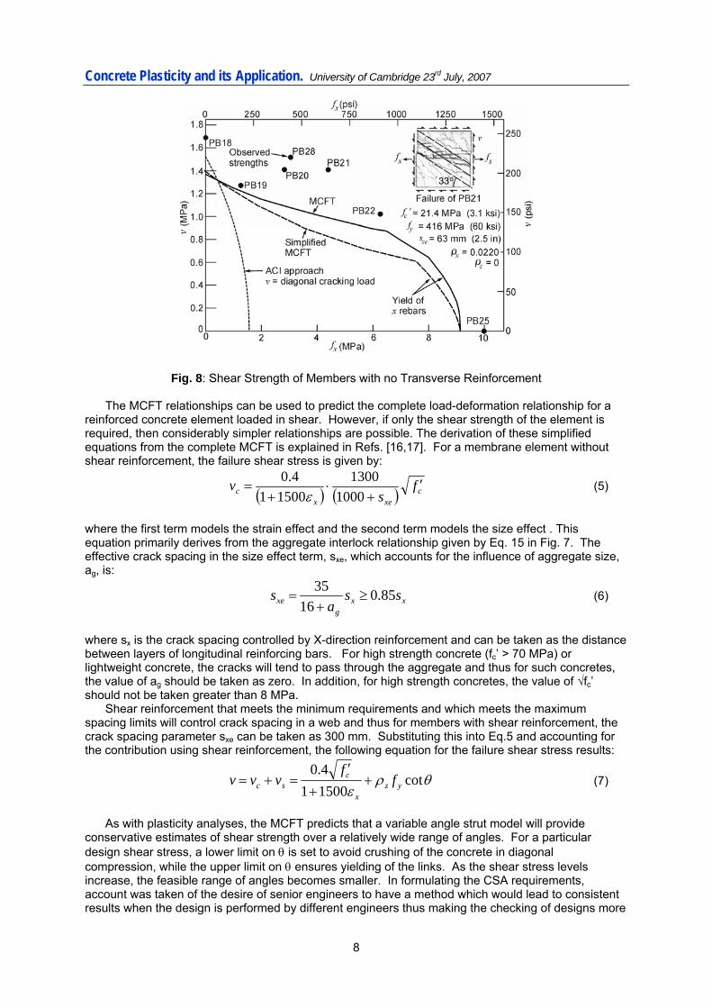
The equilibrium equations, geometric conditions and stress-strain relationships used in the MCFT are summarized in Fig. 7. The central simplifying assumption of the theory is that the average direction of principal compressive stress in the cracked concrete corresponds to the average direction of principal compressive strain and that the critical cracks are also inclined in this direction. In addition to considering average stresses and average strains in the cracked concrete and the relationships between them, the theory considers how the stresses are transmitted across the critical cracks. As an example, an element which contains no “shear” reinforcement (i.e. ρz =0) and is subjected to shear and uniaxial tension in the x direction, see Fig. 8, must transmit a shear stress, vci, across the crack interface, which is equal to the applied shear stress, v. See equilibrium Eq. 5 in Fig. 7. The ability of the crack to transmit this shear stress depends on the width of the crack, w, the maximum aggregate size, ag, and the concrete strength, fc’. The relationship used, Eq.15 in Fig. 7, was derived from the aggregate interlock experiments of Walraven [15].
7
Concrete Plasticity and its Application. University of Cambridge 23rd July, 2007
Fig. 8: Shear Strength of Members with no Transverse Reinforcement
The MCFT relationships can be used to predict the complete load-deformation relationship for a reinforced concrete element loaded in shear. However, if only the shear strength of the element is required, then considerably simpler relationships are possible. The derivation of these simplified equations from the complete MCFT is explained in Refs. [16,17]. For a membrane element without shear reinforcement, the failure shear stress is given by:
( ) ( ) cxex
c fs
v ′+
⋅+
=1000
130015001
4.0ε
(5)
where the first term models the strain effect and the second term models the size effect . This equation primarily derives from the aggregate interlock relationship given by Eq. 15 in Fig. 7. The effective crack spacing in the size effect term, sxe, which accounts for the influence of aggregate size, ag, is:
xxg
xe ssa
s 85.016
35≥
+= (6)
where sx is the crack spacing controlled by X-direction reinforcement and can be taken as the distance between layers of longitudinal reinforcing bars. For high strength concrete (fc’ > 70 MPa) or lightweight concrete, the cracks will tend to pass through the aggregate and thus for such concretes, the value of ag should be taken as zero. In addition, for high strength concretes, the value of √fc’ should not be taken greater than 8 MPa.
Shear reinforcement that meets the minimum requirements and which meets the maximum spacing limits will control crack spacing in a web and thus for members with shear reinforcement, the crack spacing parameter sxe can be taken as 300 mm. Substituting this into Eq.5 and accounting for the contribution using shear reinforcement, the following equation for the failure shear stress results:
θρε
cot150014.0
yzx
csc f
fvvv +
+
′=+= (7)
As with plasticity analyses, the MCFT predicts that a variable angle strut model will provide
conservative estimates of shear strength over a relatively wide range of angles. For a particular design shear stress, a lower limit on θ is set to avoid crushing of the concrete in diagonal compression, while the upper limit on θ ensures yielding of the links. As the shear stress levels increase, the feasible range of angles becomes smaller. In formulating the CSA requirements, account was taken of the desire of senior engineers to have a method which would lead to consistent results when the design is performed by different engineers thus making the checking of designs more
8

Concrete Plasticity and its Application. University of Cambridge 23rd July, 2007
reliable. For this reason, the CSA provisions specify the angle θ to be used for a given value of εx. The equation used is:
xεθ 700029 +°= (8)
For the elements shown in Fig. 8, it can be seen that the use of these simplified equations produces estimates of post-cracking failure shears very similar to those from the complete MCFT. Further, it might be noted that although these elements do not contain shear reinforcement, they are capable of resisting shear stresses considerably higher than those causing first diagonal cracking.
In applying the simplified equations to predict the shear strength of reinforced or prestressed concrete beams, walls, or columns, εx is taken as the longitudinal strain at mid-depth of the member, while the shear stress at this location is taken as V/(bwdv). The variable dv is the shear depth or flexural lever arm and is taken as 0.9d. For members with longitudinal reinforcement only on the flexural tension side, the crack spacing parameter, sx, can be taken as dv.
The crack widths that govern aggregate interlock capacity can be related to the longitudinal strain at mid-depth, εx. This strain can be calculated by determining the average of the longitudinal strains in the flexural tension, εt, and flexural compression, εc, flanges of a member, see Fig. 9. Because εc will typically be small in comparison to εt, due to the large stiffness of concrete in compression, it is a reasonable approximation to assume that εx is simply εt/2. For a member which does not contain inclined prestressing tendons (i.e. Vp = 0), a suitable expression for εx is:
( ))(2
5.0/1 0
pspss
ppsvx AEAE
fANVdMV+
−++=ε (9)
where N is the axial load (tension positive), As is the area of longitudinal reinforcing bars on the flexural tension side of the member, Aps is the area of prestressed reinforcement on the flexural tension side of the member, and fp0 is the stress in the prestressed steel when the strain in the surrounding concrete is zero. In this expression, the contribution of shear to the straining of the tension flange has been approximated with the assumption that 0.5cotθ is about one. If the value of εx calculated from Eq. 9 is negative, account must be taken of the compressive stiffness of the concrete in the flexural tension flange by adding the term EcAc to the reinforcement stiffnesses in the denominator.
Fig. 9: Calculation of mid-depth longitudinal strain, εx If a section fails in shear prior to reaching yield of the longitudinal reinforcement, obviously εt will not exceed the yield strain of the reinforcement. If additionally it is recognized that εc will be a small compressive strain, it can be seen that a conservative estimate of shear strength can be obtained by assuming that εx equals 0.45fy/Es. If this value of εx is substituted into Eqns. 5 and 7, very simple and conservative design equations will result which in many practical design situations will be sufficiently accurate. The equations of the MCFT are also used in the CSA strut-and-tie provisions. Recall that the EC2 and ACI strut-and-tie provisions use very similar expressions for the compressive capacity of the struts which are essentially independent of the strain state in the member. The CSA strut capacity is based on the compressive stress-compressive strain relationship for diagonally cracked concrete determined
9

Concrete Plasticity and its Application. University of Cambridge 23rd July, 2007
from the pure shear element tests, see. Eq. 13 of Fig. 7. Assuming that the compressive strain at peak stress is equal to 0.002, the crushing stress of a strut is given by:
cc
cu fff ′≤+
′= 85.0
1708.0 1ε (10)
where ε1 is the principal tensile strain in the cracked concrete calculated from a Mohr’s circle of strain as:
sss θεεε 21 cot)002.0( ++= (11)
where εs is the tensile strain in the tie crossing the strut. The sectional design method based on the modified compression field theory was first derived as part of the project to develop LRFD (load and resistance factor design) bridge design specifications by the American Association of State Highway and Transportation Officials (AASHTO) and appeared in the first edition of these specifications in 1994 [18]. Since that time, a considerable amount of experimental work, using nearly full-scale specimens, has been conducted at the University of Toronto and elsewhere to validate and verify these provisions, See Fig. 2. As much of this experimental work was conducted after the EC2 and ACI provisions were finalized, a comparison of the results of some of these experimental series with the predictions of the three design codes, EC2, ACI, and CSA, provides a true test of the predictive power of these design provisions. 5 SIZE EFFECT AND CONCRETE STRENGTH FOR MEMBERS WITHOUT LINKS In attempting to design the shear critical members shown in Fig. 3 to resist the applied shear without shear reinforcement, the engineer needs to know how changing the concrete strength or member depth influences the shear capacity. The three codes make very different predictions for the impact of these two variables. Figure 10 shows the results of two series of reinforced concrete
Fig. 10: Effect of Member Depth and Concrete Strength on Failure Shear Stress
10

Concrete Plasticity and its Application. University of Cambridge 23rd July, 2007
elements without shear reinforcement tested at the University of Toronto [19,20]. Within each series, only the depths were varied. As can be seen, the shear stress at failure varied from about 1.2 MPa for the small specimens to about 0.5 MPa for the largest specimen, a factor of 2.4 rather than the 1.6 assumed in EC2. Also note that for depths above 500 mm, there was essentially no difference between the failure shear stresses of the high strength concrete specimens and the normal strength concrete specimens. In fact, for depths above about 900 mm, the high strength concrete specimens were observed to be weaker. This perhaps surprising result is credible because it is what the CSA theoretical model predicts. For the 12 specimens in the figure, the average test to predicted ratio is 1.10 for CSA, with a coefficient of variation (COV) of 5.6%. For ACI, the average ratio is 0.77 with a COV of 31.8% while for EC2, the average ratio is 0.83 and the COV is 18.8%.
The modified compression field theory predicts that the size effect in shear is related to the distance between the longitudinal reinforcing bars rather than the absolute depth of the member. To explore this, pairs of large beams have been tested [21] with one member in each pair containing distributed longitudinal bars. Figure 11 shows the results of two of these pairs, one with normal strength and the other with high strength concrete. As can be seen, the additional layers of longitudinal steel resulted in more closely spaced cracks and, as predicted by the model, much higher shear strengths. For the normal strength pair, it is interesting that both EC2 and ACI predict that distributing the longitudinal reinforcement will lower the shear strength primarily due to the reduction in effective depth. CSA, on the other hand predicts a 34% increase in capacity while the experiments gave a 42% increase. While the inclusion of distributed steel without shear reinforcement is of limited practicality, these tests do confirm that the size effect is controlled by crack spacing rather than absolute size.
Fig. 11: Influence of Distributed Longitudinal Reinforcement on Failure Shear Stress
7 STRAIN EFFECT OR REINFORCEMENT AMOUNT? The 1962 seminal ACI shear report [7] proposed that the two prime parameters influencing failure shear stress of a member without shear reinforcement are √fc’ as a measure of the concrete tensile strength, and M/(ρℓVd) as a measure of the stress in the longitudinal reinforcement. The 2004 CSA code adopts a rather similar approach with respect to the strain effect in shear. In actual designs, the amount of longitudinal reinforcement is proportionally increased as the moment is increased and, hence, the parameter M/(ρℓVd) will tend to be fairly constant. For the standard type of shear experiment in which point loads are applied to simple spans, M/(ρℓVd) is equivalent to (a/d)/ρℓ and this parameter is proportional to the strain in the longitudinal reinforcement at shear failure. Unlike the practical case where (a/d)/ρℓ is fairly uniform, in laboratory experiments a/d and ρℓ are independent variables and, further, ρℓ is often intentionally made unrealistically high to ensure that a shear failure occurs before a flexural failure. If empirical relationships are derived to provide a good fit to these
11
Concrete Plasticity and its Application. University of Cambridge 23rd July, 2007
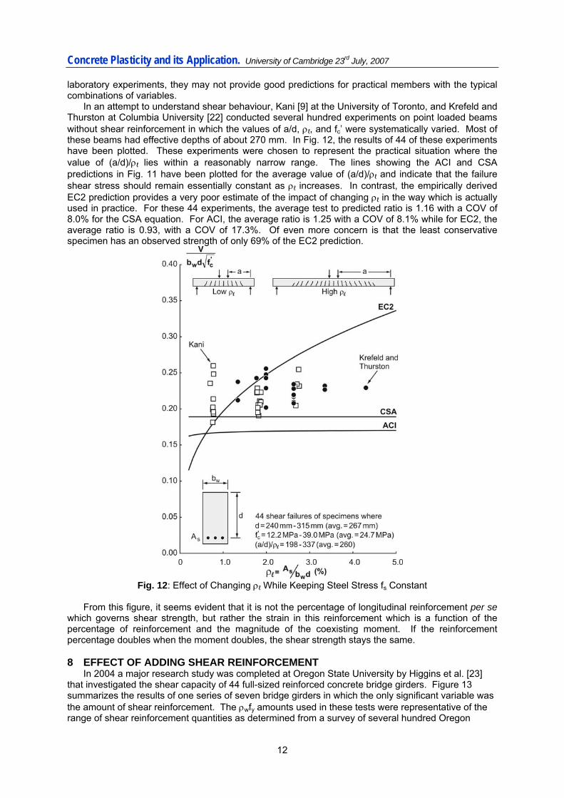
laboratory experiments, they may not provide good predictions for practical members with the typical combinations of variables. In an attempt to understand shear behaviour, Kani [9] at the University of Toronto, and Krefeld and Thurston at Columbia University [22] conducted several hundred experiments on point loaded beams without shear reinforcement in which the values of a/d, ρℓ, and fc’ were systematically varied. Most of these beams had effective depths of about 270 mm. In Fig. 12, the results of 44 of these experiments have been plotted. These experiments were chosen to represent the practical situation where the value of (a/d)/ρℓ lies within a reasonably narrow range. The lines showing the ACI and CSA predictions in Fig. 11 have been plotted for the average value of (a/d)/ρℓ and indicate that the failure shear stress should remain essentially constant as ρℓ increases. In contrast, the empirically derived EC2 prediction provides a very poor estimate of the impact of changing ρℓ in the way which is actually used in practice. For these 44 experiments, the average test to predicted ratio is 1.16 with a COV of 8.0% for the CSA equation. For ACI, the average ratio is 1.25 with a COV of 8.1% while for EC2, the average ratio is 0.93, with a COV of 17.3%. Of even more concern is that the least conservative specimen has an observed strength of only 69% of the EC2 prediction.
Fig. 12: Effect of Changing ρℓ While Keeping Steel Stress fs Constant
From this figure, it seems evident that it is not the percentage of longitudinal reinforcement per se which governs shear strength, but rather the strain in this reinforcement which is a function of the percentage of reinforcement and the magnitude of the coexisting moment. If the reinforcement percentage doubles when the moment doubles, the shear strength stays the same. 8 EFFECT OF ADDING SHEAR REINFORCEMENT
In 2004 a major research study was completed at Oregon State University by Higgins et al. [23] that investigated the shear capacity of 44 full-sized reinforced concrete bridge girders. Figure 13 summarizes the results of one series of seven bridge girders in which the only significant variable was the amount of shear reinforcement. The ρwfy amounts used in these tests were representative of the range of shear reinforcement quantities as determined from a survey of several hundred Oregon
12

Concrete Plasticity and its Application. University of Cambridge 23rd July, 2007
bridge girders. As can be seen on the plot, adding even a small amount of shear reinforcement greatly increased the failure shear stress. For higher amounts of shear reinforcement, yielding of the longitudinal reinforcement began to limit the shear capacity with specimen number 1 failing in flexure. Also shown in the figure are the failure shear stresses predicted by program Response-2000 (R2k) [24]. This sectional analysis program assumes that plane sections remain plane and using the 15 equations of the MCFT in Fig. 7 at multiple locations over the depth, predicts the shear-stress distribution and the strain states for all loads up to failure. These R2k analyses used the reported stress-strain characteristics of the longitudinal and shear reinforcement. Thus, the yield plateau of the link reinforcement ended at a strain of 0.014 and the ultimate strength of 544 MPa was reached at a strain of 0.14. The line shown on the figure uses the average concrete strength and the average longitudinal reinforcement yield strength. If the actual material strengths are used for each specimen, even better agreement is obtained between the experiments and the predictions. For these seven bridge girders, the average test to predicted ratio is 0.99 and the COV is 2.4%. Furthermore, not only are the strengths excellently predicted, but so too are the complete load-deformation relationships. For example, for Beam 3 shown in the figure, the predicted midspan deflection at shear failure is 30 mm compared to the observed displacement of 27 mm. This demonstrates that the modified compression field theory provides an excellent basis for developing accurate shear design procedures.
Fig. 13: Effect of Adding Shear Reinforcement
As shown in Fig. 14, none of the code design methods can predict the strength of these Oregon beams as well as the full equations of the MCFT. It must be appreciated, however, that these code formulations use only the yield stress of the links and neglect strain hardening which, in this case, is quite important. In addition, the provisions used for angle of principal compression are generally fairly coarse estimates of what the angle would actually be in a particular member. For beam 3 shown in Figs. 13 and 14, for example, the EC2 angle of principal compression was taken as 21.8º (cotθ = 2.5), the CSA code equation predicts 35.1º for this beam, and the ACI provisions use 45º. From the failure crack pattern of this beam shown in Fig. 13, the actual angle of the cracks at failure is approximately 36º. Overall, the strength of the member without shear reinforcement is modelled better by EC2 and
13
Concrete Plasticity and its Application. University of Cambridge 23rd July, 2007
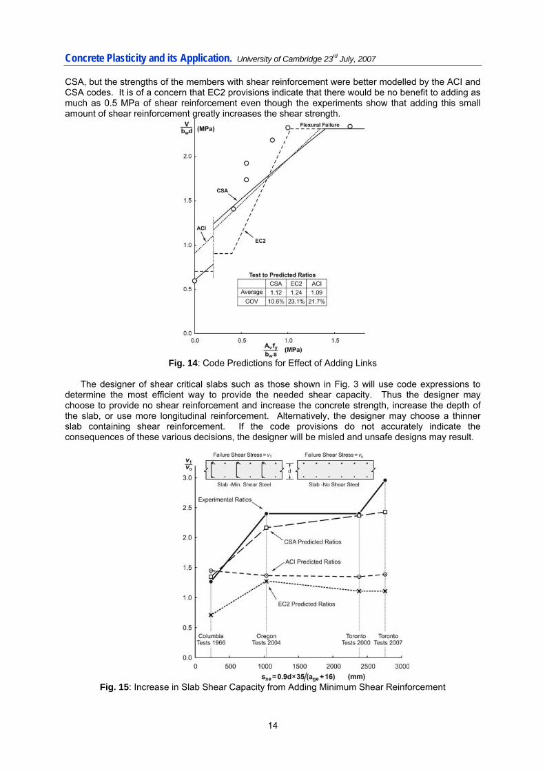
CSA, but the strengths of the members with shear reinforcement were better modelled by the ACI and CSA codes. It is of a concern that EC2 provisions indicate that there would be no benefit to adding as much as 0.5 MPa of shear reinforcement even though the experiments show that adding this small amount of shear reinforcement greatly increases the shear strength.
Fig. 14: Code Predictions for Effect of Adding Links
The designer of shear critical slabs such as those shown in Fig. 3 will use code expressions to determine the most efficient way to provide the needed shear capacity. Thus the designer may choose to provide no shear reinforcement and increase the concrete strength, increase the depth of the slab, or use more longitudinal reinforcement. Alternatively, the designer may choose a thinner slab containing shear reinforcement. If the code provisions do not accurately indicate the consequences of these various decisions, the designer will be misled and unsafe designs may result.
Fig. 15: Increase in Slab Shear Capacity from Adding Minimum Shear Reinforcement
14
Concrete Plasticity and its Application. University of Cambridge 23rd July, 2007
As an example, consider the predictions of the three codes about the increase in shear capacity that will result from adding minimum shear reinforcement. Figure 15 uses the results from four sets of experiments [22,23,19,20] in which companion specimens were tested with, v1, and without, v0, minimum shear reinforcement. The figure shows how the ratio of v1/v0 varies with the effective crack spacing. Because minimum shear reinforcement mitigates the size effect, its beneficial influence is more pronounced for members with larger depths. As can be seen, the CSA provisions, which are based on the MCFT, model very well the observed behaviour while the empirically based EC2 and ACI provide very poor guidance to the engineer in this situation.
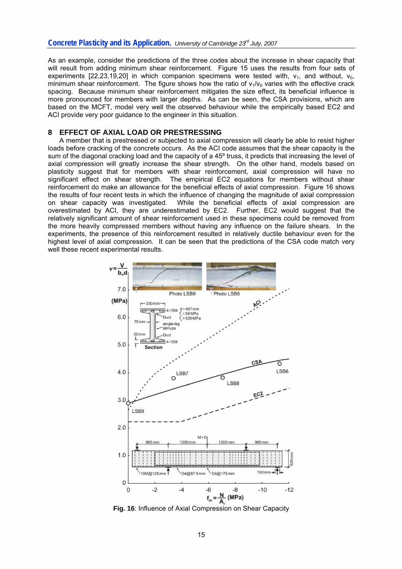
8 EFFECT OF AXIAL LOAD OR PRESTRESSING A member that is prestressed or subjected to axial compression will clearly be able to resist higher loads before cracking of the concrete occurs. As the ACI code assumes that the shear capacity is the sum of the diagonal cracking load and the capacity of a 45º truss, it predicts that increasing the level of axial compression will greatly increase the shear strength. On the other hand, models based on plasticity suggest that for members with shear reinforcement, axial compression will have no significant effect on shear strength. The empirical EC2 equations for members without shear reinforcement do make an allowance for the beneficial effects of axial compression. Figure 16 shows the results of four recent tests in which the influence of changing the magnitude of axial compression on shear capacity was investigated. While the beneficial effects of axial compression are overestimated by ACI, they are underestimated by EC2. Further, EC2 would suggest that the relatively significant amount of shear reinforcement used in these specimens could be removed from the more heavily compressed members without having any influence on the failure shears. In the experiments, the presence of this reinforcement resulted in relatively ductile behaviour even for the highest level of axial compression. It can be seen that the predictions of the CSA code match very well these recent experimental results.
Fig. 16: Influence of Axial Compression on Shear Capacity
15
Concrete Plasticity and its Application. University of Cambridge 23rd July, 2007
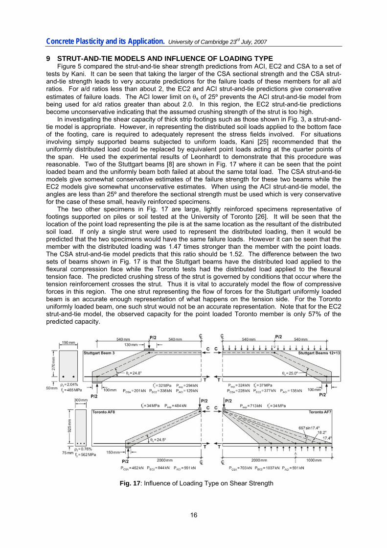
9 STRUT-AND-TIE MODELS AND INFLUENCE OF LOADING TYPE Figure 5 compared the strut-and-tie shear strength predictions from ACI, EC2 and CSA to a set of
tests by Kani. It can be seen that taking the larger of the CSA sectional strength and the CSA strut-and-tie strength leads to very accurate predictions for the failure loads of these members for all a/d ratios. For a/d ratios less than about 2, the EC2 and ACI strut-and-tie predictions give conservative estimates of failure loads. The ACI lower limit on θs of 25º prevents the ACI strut-and-tie model from being used for a/d ratios greater than about 2.0. In this region, the EC2 strut-and-tie predictions become unconservative indicating that the assumed crushing strength of the strut is too high.
In investigating the shear capacity of thick strip footings such as those shown in Fig. 3, a strut-and-tie model is appropriate. However, in representing the distributed soil loads applied to the bottom face of the footing, care is required to adequately represent the stress fields involved. For situations involving simply supported beams subjected to uniform loads, Kani [25] recommended that the uniformly distributed load could be replaced by equivalent point loads acting at the quarter points of the span. He used the experimental results of Leonhardt to demonstrate that this procedure was reasonable. Two of the Stuttgart beams [8] are shown in Fig. 17 where it can be seen that the point loaded beam and the uniformly beam both failed at about the same total load. The CSA strut-and-tie models give somewhat conservative estimates of the failure strength for these two beams while the EC2 models give somewhat unconservative estimates. When using the ACI strut-and-tie model, the angles are less than 25º and therefore the sectional strength must be used which is very conservative for the case of these small, heavily reinforced specimens.
The two other specimens in Fig. 17 are large, lightly reinforced specimens representative of footings supported on piles or soil tested at the University of Toronto [26]. It will be seen that the location of the point load representing the pile is at the same location as the resultant of the distributed soil load. If only a single strut were used to represent the distributed loading, then it would be predicted that the two specimens would have the same failure loads. However it can be seen that the member with the distributed loading was 1.47 times stronger than the member with the point loads. The CSA strut-and-tie model predicts that this ratio should be 1.52. The difference between the two sets of beams shown in Fig. 17 is that the Stuttgart beams have the distributed load applied to the flexural compression face while the Toronto tests had the distributed load applied to the flexural tension face. The predicted crushing stress of the strut is governed by conditions that occur where the tension reinforcement crosses the strut. Thus it is vital to accurately model the flow of compressive forces in this region. The one strut representing the flow of forces for the Stuttgart uniformly loaded beam is an accurate enough representation of what happens on the tension side. For the Toronto uniformly loaded beam, one such strut would not be an accurate representation. Note that for the EC2 strut-and-tie model, the observed capacity for the point loaded Toronto member is only 57% of the predicted capacity.
Fig. 17: Influence of Loading Type on Shear Strength
16
Concrete Plasticity and its Application. University of Cambridge 23rd July, 2007
17
10 CONCLUSIONS The development of the current ACI shear design provisions occurred in the years following the sudden shear failures of the large Air Force warehouse girders shown in Fig. 1. In the years since, many other major structures have collapsed due to brittle shear failures including the Sleipner offshore platform, and the Hanshin Expressway. On Sept. 30th 2006, five people were killed in the sudden collapse of a highway bridge in Laval, Quebec due to the shear failure of a thick concrete slab not containing shear reinforcement. These failures highlight the need for shear design provisions for reinforced concrete which are solidly based on an adequate theory. A characteristic of an adequate theory is that it can accurately predict which parameters are important and the consequences of changing these parameters. The provisions which were used to perform the design of the collapsed structures were empirical equations derived from a large number of laboratory experiments. But because shear resistance is such a complex phenomenon and depends on so many different variables, such empirical equations can lead to design decisions which are dangerous. This paper has introduced a simple general theory for predicting the shear strength of reinforced and prestressed concrete members either with or without shear reinforcement. The theory forms the basis of the shear design provisions of the 2004 Canadian Standards Association “Design of Concrete Structures” code. Because the procedures are based on an adequate theory, they capture the influence of all the important parameters studied to date. While research on the topic is continuing and deeper understanding is being developed of the basic mechanisms of shear transfer, it is believed that the theory developed to date offers a solid basis for shear design. In the context of concrete plasticity, it is already apparent that the mechanisms that transfer shear across the crack have considerable ability to redistribute shear making possible the simplifications incorporated in the Canadian code. In addition, the research on the ability of cracked concrete to transmit compressive stress and the relationship between the maximum compressive stress which can be transmitted and the coexisting principal tensile strain can be regarded as a more rigorous way of determining the effective concrete compressive stress used in other formulations of concrete plasticity. ACKNOWLEDGEMENTS
The authors would like to express their gratitude to the Natural Sciences and Engineering Research Council of Canada for a series of grants that have made possible the long-term research project on shear design of reinforced concrete at the University of Toronto. REFERENCES [1] Cross, H., “Limitations and Applications of Structural Analysis”, Engineering News-Record,
Oct. 17th 1935, pp. 535-537. [2] Hooke, R., “Lectures De Potentia Restitutiva, or of Spring-Explaining the Power of Springing
Bodies”, Printed for John Martyn, Printer to The Royal Society at the Bell in St. Paul’s Church-Yard, 1678, 24 pp.
[3] European Committee for Standardization, CEN, EN 1992-1-1:2004 Eurocode 2: Design of Concrete Structures- Part 1-1: General rules and rules for buildings, Brussels, Belgium, 2004, 225 pp.
[4] CSA Committee A23.3, Design of Concrete Structures, Canadian Standards Association, Mississauga, Ontario, Canada, 2004, 214 pp.
[5] ACI Committee 318, Building Code Requirements for Reinforced Concrete (ACI 318-05) and Commentary (318R-05), American Concrete Institute, Farmington Hills, 2005, 430 pp.
[6] Anderson, B.G., “Rigid Frame Failures,” ACI Journal, Vol. 53, No. 1, Jan. 1957, pp. 625-636. [7] ACI-ASCE Committee 326, “Shear and Diagonal Tension,” ACI Journal, Proceedings, V.59,
No.1, 2, and 3, Jan., Feb., and Mar., 1962, pp. 1-30, 277-334, and 352-396 and discussion and closure, Oct 1962 pp. 1323-1349.
[8] Leonhardt, F., and Walther, R., “The Stuttgart Shear Tests 1961,” A translation of the articles that appeared in Beton und Stahlbetonbau, V.56, No. 12, 1961 and V.57, No. 2,3,6,7 and 8, 1962, Cement and Concrete Association Library Translation No. 111, Wexham Springs, United Kingdom, Dec. 1964, 134 pp.
[9] Kani, M.W., Huggins, M.W., and Wittkopp, R.R., Kani on Shear in Reinforced Concrete, Department of Civil Engineering, University of Toronto, Toronto, 1979, 225 pp.
[10] Fenwick, R.C., and Paulay, T., “Mechanisms of Shear Resistance of Concrete Beams,” Journal of the Structural Division, ASCE, V. 94, No. ST10, Oct. 1968, pp. 2235-2350.

Concrete Plasticity and its Application. University of Cambridge 23rd July, 2007
18
[11] Zsutty, T.C., “Beam Shear Strength Prediction by Analysis of Existing Data,” ACI Journal, Proceedings, Vol. 65, No. 11, Nov. 1968, pp. 943-951.
[12] CEB-FIP, Model code for concrete structures: CEB-FIP International Recommendations, 3rd Ed., Comité Euro-Internationale du Béton/Fèdèration Internationale de la Précontrainte, Paris, 1978, 348 pp.
[13] Vecchio, F.J., and Collins, M.P., “The Modified Compression Field Theory for Reinforced Concrete Elements Subjected to Shear,” ACI Journal, Proceedings, V. 83 No. 2, Mar.-Apr. 1986, pp. 219-231.
[14] Collins, M.P., “Towards a rational theory for RC members in shear,” Journal of the Structural Division, ASCE, 104(4): 1978, pp. 649-666.
[15] Walraven, J.C., “Fundamental Analysis of Aggregate Interlock,” Journal of the Structural Division, ASCE, Vol. 107, No. ST11, Nov. 1981, pp 2245-2270.
[16] Bentz, E.C., and Collins, M.P., “Development of the 2004 CSA A23.3 Shear Provisions for Reinforced Concrete,” Canadian Journal of Civil Engineering, V.33, No.5, May 2006, pp.521-534.
[17] Bentz, E.C., Vecchio, F.J., and Collins, M.P., “ The Simplified MCFT for Calculating the Shear Strength of Reinforced Concrete Elements”, ACI Structural Journal, V.103, No. 4, July-Aug. 2006, pp.614-624.
[18] AASHTO, LRFD Bridge Design Specifications and Commentary, 1st Edition, American Association of State Highway and Transportation Officials, Washington, 1994, 1091 pp.
[19] Lubell, A., Sherwood, T., Bentz, E., and Collins, M.P., “Safe Shear Design of Large, Wide Beams,” Concrete International, V.26, No.1, Jan. 2004, pp. 66-78.
[20] Sherwood, E.G., Bentz, E.C., and Collins, M.P., “Effect of Aggregate Size on Beam-Shear Strength of Thick Slabs,” ACI Structural Journal, V. 104, No. 2, Mar.-Apr. 2007, pp. 180-190.
[21] Collins, M.P., and Kuchma, D., “How Safe Are Our Large, Lightly-Reinforced Concrete Beams, Slabs and Footings?” ACI Structural Journal, V. 96, No. 4, July-Aug. 1999, pp. 482-490.
[22] Krefeld, W.J. and Thurston, C.W., “Studies of the Shear and Diagonal Tension Strength of Simply-Supported Reinforced Concrete Beams,” ACI Journal, Vol. 63, No. 4, Apr. 1966, pp. 451-476.
[23] Higgins, C., Miller, T.H., Rosowsky, D.V., Yim, S.C., Potisuk,T., Daniels,T.K., Nicholas, B.S., Robelo, M.J., Lee, A.Y., and Forrest, R.W., “Assessment Methodology for Diagonally Cracked Reinforced Concrete Deck Girders”, Final Report for Oregon Department of Transportation and the Federal Highway Administration, Final Report SPR 350, SR 500-091, October 2004, 340 pages plus appendices
[24] Bentz, E.C. 2000. Sectional analysis of reinforced concrete members. Ph.D. Thesis, Department of Civil Engineering, University of Toronto, 198 pp.
[25] Kani, G.N.J., “ Basic Facts Concerning Shear Failure”, ACI Journal, Proceedings, V. 63, No. 6, June 1966, pp. 675-692.
[26] Uzel, A., Podgorniak, B., Bentz, E.C., Collins, M.P., “ Design of Large Footings for One-Way Shear”, paper submitted to ACI Structural Journal Nov. 2006.