Sharp Ar 160 & 161ar-161 Service Manual
68
CODE: 00ZAR161//A1E DIGITAL COPIER AR-160 MODEL AR-161 Parts marked with "!" is important for maintaining the safety of the set. Be sure to replace these parts with specified ones for maintaining the safty and performance of the set. [ 1 ] GENERAL . . . . . . . . . . . . . . . . . . . . . . . . . . . . . . . . . . . . . . . . . . . . . . . . 1-1 [ 2 ] SPECIFI CATI ONS . . . . . . . . . . . . . . . . . . . . . . . . . . . . . . . . . . . . . . . . . 2-1 [ 3 ] CONSUMABLE PARTS . . . . . . . . . . . . . . . . . . . . . . . . . . . . . . . . . . . . . 3-1 [ 4 ] EXT ERNA L VIEWS AND INTERNAL STRUCTURE . . . . . . . . . . . . . . . 4-1 [ 5 ] UNPACKING AND INSTALLATION . . . . . . . . . . . . . . . . . . . . . . . . . . . . 5-1 [ 6 ] OPERATIONAL DESCRIPTIONS . . . . . . . . . . . . . . . . . . . . . . . . . . . . . 6-1 [ 7 ] ADJ USTMENTS . . . . . . . . . . . . . . . . . . . . . . . . . . . . . . . . . . . . . . . . . . . 7-1 [ 8 ] SIMULATIONS . . . . . . . . . . . . . . . . . . . . . . . . . . . . . . . . . . . . . . . . . . . . 8-1 [ 9 ] USER PROGRA M . . . . . . . . . . . . . . . . . . . . . . . . . . . . . . . . . . . . . . . . . . 9-1 [10] TROU BLE CODE LIST . . . . . . . . . . . . . . . . . . . . . . . . . . . . . . . . . . . . . 10-1 [11] MAIN TENA NCE . . . . . . . . . . . . . . . . . . . . . . . . . . . . . . . . . . . . . . . . . . 11-1 [12] DISA SSE MBLY AND ASSEMBLY . . . . . . . . . . . . . . . . . . . . . . . . . . . . 12-1 [13] ELEC TRICA L SECTION . . . . . . . . . . . . . . . . . . . . . . . . . . . . . . . . . . . . 13-1 [14] CIRCUIT DIAGRAM . . . . . . . . . . . . . . . . . . . . . . . . . . . . . . . . . . . . . . . 14-1 [15] ACTU AL WI RING DIAGRAM . . . . . . . . . . . . . . . . . . . . . . . . . . . . . . . . 15-1 CONTENTS AR-161 SHARP CORPORATION This document has been published to be used for after sales service only. The contents are subject to change without notice.
-
Upload
rostocanie -
Category
Documents
-
view
269 -
download
0
Transcript of Sharp Ar 160 & 161ar-161 Service Manual

7/27/2019 Sharp Ar 160 & 161ar-161 Service Manual
http://slidepdf.com/reader/full/sharp-ar-160-161ar-161-service-manual 1/67
CODE: 00ZAR161//A1E
DIGITAL COPIER
AR-160MODEL AR-161
Parts marked with "!" is important for maintaining the safety of the set. Be sure to replace these parts with specifiedones for maintaining the safty and performance of the set.
[ 1 ] GENERAL . . . . . . . . . . . . . . . . . . . . . . . . . . . . . . . . . . . . . . . . . . . . . . . . 1-1
[ 2 ] SPECIFICATIONS . . . . . . . . . . . . . . . . . . . . . . . . . . . . . . . . . . . . . . . . . 2-1
[ 3 ] CONSUMABLE PARTS . . . . . . . . . . . . . . . . . . . . . . . . . . . . . . . . . . . . . 3-1
[ 4 ] EXTERNAL VIEWS AND INTERNAL STRUCTURE . . . . . . . . . . . . . . . 4-1
[ 5 ] UNPACKING AND INSTALLATION . . . . . . . . . . . . . . . . . . . . . . . . . . . . 5-1[ 6 ] OPERATIONAL DESCRIPTIONS . . . . . . . . . . . . . . . . . . . . . . . . . . . . . 6-1
[ 7 ] ADJUSTMENTS . . . . . . . . . . . . . . . . . . . . . . . . . . . . . . . . . . . . . . . . . . . 7-1
[ 8 ] SIMULATIONS . . . . . . . . . . . . . . . . . . . . . . . . . . . . . . . . . . . . . . . . . . . . 8-1
[ 9 ] USER PROGRAM . . . . . . . . . . . . . . . . . . . . . . . . . . . . . . . . . . . . . . . . . . 9-1
[10] TROUBLE CODE LIST . . . . . . . . . . . . . . . . . . . . . . . . . . . . . . . . . . . . . 10-1
[11] MAINTENANCE . . . . . . . . . . . . . . . . . . . . . . . . . . . . . . . . . . . . . . . . . . 11-1
[12] DISASSEMBLY AND ASSEMBLY . . . . . . . . . . . . . . . . . . . . . . . . . . . . 12-1
[13] ELECTRICAL SECTION . . . . . . . . . . . . . . . . . . . . . . . . . . . . . . . . . . . . 13-1
[14] CIRCUIT DIAGRAM . . . . . . . . . . . . . . . . . . . . . . . . . . . . . . . . . . . . . . . 14-1
[15] ACTUAL WIRING DIAGRAM . . . . . . . . . . . . . . . . . . . . . . . . . . . . . . . . 15-1
CONTENTS
AR-161
SHARP CORPORATION
This document has been published to be used
for after sales service only.The contents are subject to change without notice.
7/27/2019 Sharp Ar 160 & 161ar-161 Service Manual
http://slidepdf.com/reader/full/sharp-ar-160-161ar-161-service-manual 2/67
AR-161 AR-161
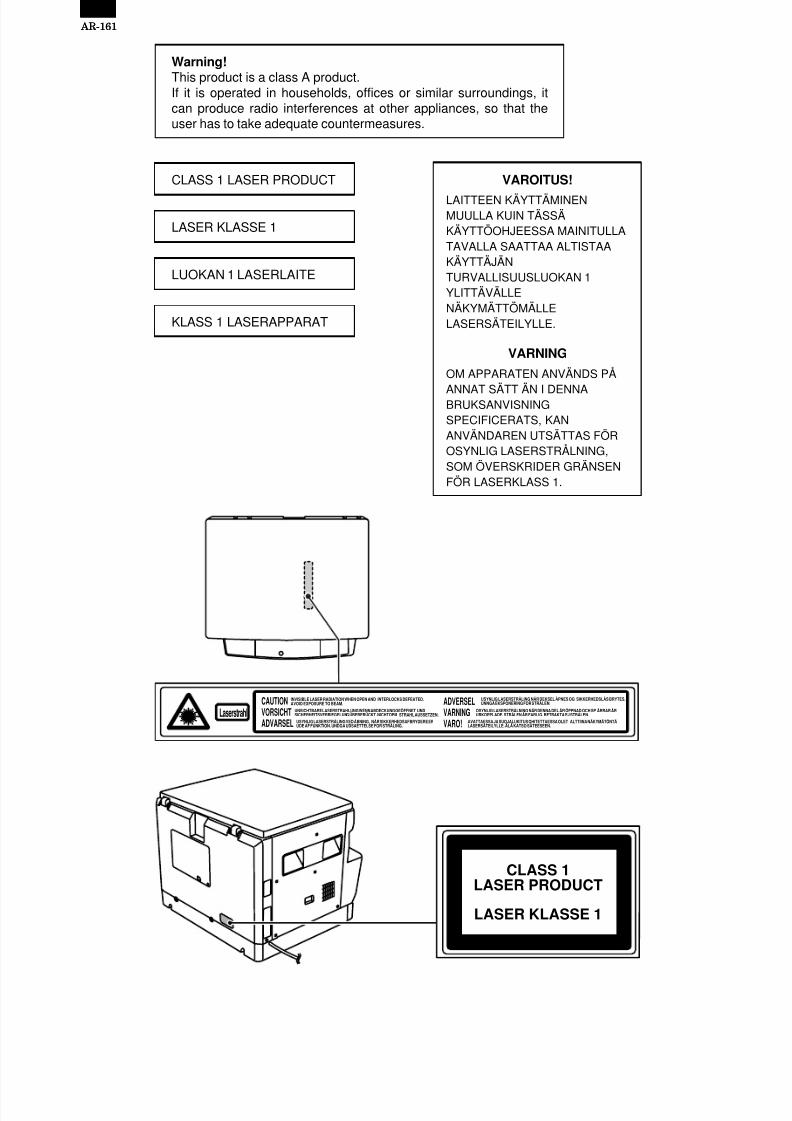
Warning!This product is a class A product.If it is operated in households, offices or similar surroundings, itcan produce radio interferences at other appliances, so that theuser has to take adequate countermeasures.
CLASS 1 LASER PRODUCT
LASER KLASSE 1
LUOKAN 1 LASERLAITE
KLASS 1 LASERAPPARAT
VAROITUS!
LAITTEEN KÄYTTÄMINENMUULLA KUIN TÄSSÄKÄYTTÖOHJEESSA MAINITULLATAVALLA SAATTAA ALTISTAAKÄYTTÄJÄNTURVALLISUUSLUOKAN 1YLITTÄVÄLLENÄKYMÄTTÖMÄLLELASERSÄTEILYLLE.
VARNING
OM APPARATEN ANVÄNDS PÅ
ANNAT SÄTT ÄN I DENNABRUKSANVISNINGSPECIFICERATS, KANANVÄNDAREN UTSÄTTAS FÖROSYNLIG LASERSTRÅLNING,SOM ÖVERSKRIDER GRÄNSENFÖR LASERKLASS 1.
CAUTION
VORSICHT
ADVARSEL
ADVERSEL
VARNING
VARO!
INVISIBLE LASER RADIATION WHEN OPEN AND INTERLOCKS DEFEATED.AVOID EXPOSURE TO BEAM.
UNSICHTBARE LASERSTRAHLUNG WENN ABDECKUNG GEÖFFNET UNDSICHERHEITSVERRIEGELUNG ÜBERERÜCKT. NICHT DEM STRAHL AUSSETZEN.
USYNLIG LASERSTRÅLING VED ÅBNING, NÅR SIKKERHEDSAFBRYDERE ERUDE AF FUNKTION. UNDGA UDSAETTELSE FOR STRÅLING.
USYNLIG LASERSTRÅLING NÅR DEKSEL ÅPNES OG SIKKERHEDSLÅS BRYTES.UNNGÅ EKSPONERING FOR STRÅLEN.
OSYNLIG LASERSTRÅLNING NÄR DENNA DEL ÄR ÖPPNAD OCH SP ÄRRAR ÄRURKOPPLADE. STRÅLEN ÄR FARLIG. BETRAKTA EJ STRÅLEN.
AVATTAESSA JA SUOJALUKITUS OHITETTAESSA OLET ALTTIINA NÄKYMÄTÖNTÄLASERSÄTEILYLLE. ÄLÄ KATSO SÄTEESEEN.
Laserstrahl
CLASS 1
LASER PRODUCT
LASER KLASSE 1
7/27/2019 Sharp Ar 160 & 161ar-161 Service Manual
http://slidepdf.com/reader/full/sharp-ar-160-161ar-161-service-manual 3/67
CONTENTS
[ 1 ] GENERAL . . . . . . . . . . . . . . . . . . . . . . . . . . . . . . . 1-11. General . . . . . . . . . . . . . . . . . . . . . . . . . . . . . . . 1-1
2. Target user copy volume: Monthly average . . . 1-1
3. Main features . . . . . . . . . . . . . . . . . . . . . . . . . . . 1-1
4. System configuration . . . . . . . . . . . . . . . . . . . . . 1-1
5. Copier installation . . . . . . . . . . . . . . . . . . . . . . . 1-1
[ 2 ] SPECIFICATIONS . . . . . . . . . . . . . . . . . . . . . . . . 2-1
1. Copy mode . . . . . . . . . . . . . . . . . . . . . . . . . . . . 2-1
[ 3 ] CONSUMABLE PARTS . . . . . . . . . . . . . . . . . . . 3-11. Supply system table . . . . . . . . . . . . . . . . . . . . . 3-1
2. Environment conditions . . . . . . . . . . . . . . . . . . . 3-3
3. Production number identification . . . . . . . . . . . . 3-3
4. Consumable parts recycling procedure . . . . . . 3-4
[ 4 ] EXTERNAL VIEWS AND INTERNALSTRUCTURE . . . . . . . . . . . . . . . . . . . . . . . . . . . . . 4-11. Appearance . . . . . . . . . . . . . . . . . . . . . . . . . . . . 4-1
2. Internal . . . . . . . . . . . . . . . . . . . . . . . . . . . . . . . 4-13. Operation Section . . . . . . . . . . . . . . . . . . . . . . . 4-2
4. Motor, solenoid, clutch . . . . . . . . . . . . . . . . . . . 4-3
5. Sensor, switch . . . . . . . . . . . . . . . . . . . . . . . . . . 4-4
6. PWB unit . . . . . . . . . . . . . . . . . . . . . . . . . . . . . . 4-5
7. Cross sectional view . . . . . . . . . . . . . . . . . . . . . 4-6
[ 5 ] UNPACKING AND INSTALLATION . . . . . . . . . 5-11. Installation of machine . . . . . . . . . . . . . . . . . . . 5-1
2. Removal of protective material and fixing screw 5-1
3. Installation of developing cartridge . . . . . . . . . . 5-1
4. Removal and storage of fixing screw . . . . . . . . 5-25. Changing the copy paper size in the tray . . . . . 5-3
[ 6 ] OPERATIONAL DESCRIPTIONS . . . . . . . . . . . 6-1
1. Outline of operation . . . . . . . . . . . . . . . . . . . . . . 6-1
2. Scanner section . . . . . . . . . . . . . . . . . . . . . . . . 6-1
3. Process section . . . . . . . . . . . . . . . . . . . . . . . . 6-2
4. Laser unit . . . . . . . . . . . . . . . . . . . . . . . . . . . . . 6-5
5. Paper feed section . . . . . . . . . . . . . . . . . . . . . . 6-6
6. Fusing section . . . . . . . . . . . . . . . . . . . . . . . . . . 6-7
[ 7 ] ADJUSTMENTS . . . . . . . . . . . . . . . . . . . . . . . . . . 7-11. Adjustment item list . . . . . . . . . . . . . . . . . . . . . . 7-1
2. Copier adjustment . . . . . . . . . . . . . . . . . . . . . . . 7-1
[ 8 ] SIMULATIONS . . . . . . . . . . . . . . . . . . . . . . . . . . . 8-1
1. Entering the simulation mode . . . . . . . . . . . . . . 8-1
2. Cancelling the simulation mode . . . . . . . . . . . . 8-1
3. List of simulations . . . . . . . . . . . . . . . . . . . . . . . 8-1
4. Contents of simulations . . . . . . . . . . . . . . . . . . . 8-2
[ 9 ] USER PROGRAM . . . . . . . . . . . . . . . . . . . . . . . . 9-11. User program functions . . . . . . . . . . . . . . . . . . . 9-1
2. Setting change procedure . . . . . . . . . . . . . . . . . 9-2
3. Department counter setting . . . . . . . . . . . . . . . . 9-2
[10] TROUBLE CODE LIST . . . . . . . . . . . . . . . . . . . 10-1
[11] MAINTENANCE . . . . . . . . . . . . . . . . . . . . . . . . . 11-11. Maintenance table . . . . . . . . . . . . . . . . . . . . . . 11-1
[12] DISASSEMBLY AND ASSEMBLY . . . . . . . . . 12-11. High voltage section . . . . . . . . . . . . . . . . . . . . 12-1
2. Optical section . . . . . . . . . . . . . . . . . . . . . . . . . 12-1
3. Fusing section . . . . . . . . . . . . . . . . . . . . . . . . 12-2
4. Paper exit section . . . . . . . . . . . . . . . . . . . . . . 12-4
5. MCU . . . . . . . . . . . . . . . . . . . . . . . . . . . . . . . . 12-6
6. Optical frame unit . . . . . . . . . . . . . . . . . . . . . . 12-6
7. LSU . . . . . . . . . . . . . . . . . . . . . . . . . . . . . . . . . 12-6
8. Tray paper feed section/ Paper transport section . . . . . . . . . . . . . . . . . . 12-7
9. Manual multi paper feed section . . . . . . . . . . 12-8
10. Power section . . . . . . . . . . . . . . . . . . . . . . . 12-1011. Developing section . . . . . . . . . . . . . . . . . . . . 12-11
12. Process section . . . . . . . . . . . . . . . . . . . . . . 12-12
[13] ELECTRICAL SECTION . . . . . . . . . . . . . . . . . . 13-1
1. Outline . . . . . . . . . . . . . . . . . . . . . . . . . . . . . . . 13-1
2. MCU . . . . . . . . . . . . . . . . . . . . . . . . . . . . . . . . 13-2
3. CCD PWB . . . . . . . . . . . . . . . . . . . . . . . . . . . 13-13
[14] CIRCUIT DIAGRAM . . . . . . . . . . . . . . . . . . . . . . 14-1
[15] ACTUAL WIRING DIAGRAM . . . . . . . . . . . . . 15-1
AR-161

7/27/2019 Sharp Ar 160 & 161ar-161 Service Manual
http://slidepdf.com/reader/full/sharp-ar-160-161ar-161-service-manual 4/67
[1] GENERAL
1. General
This model is a digital personal copier produced with key words of"Comfort able copy, Clear copy, Easy copy" providing high copy per-formances and copy productivity.
2. Target user copy volume: Monthly
averageStand-alone copier: 2000~3000 sheets
Compound machine: 4000~5000 sheets
3. Main features
A. High-speed laser copying• First-copy time is only 7.2 seconds (normal mode).
• Copying speed is 16 copies/min., which adapts to business use,allowing improvement of working efficiency.
B. High-quality digital image
• High-quality copying at 600 dpi is performed.
• In addition to the automatic exposure mode, the manual exposurecan be adjusted in five steps.
• The photo mode copying function allows clear copying of delicatehalftone original images such as monochrome photos and colorphotos. Photo mode is adjustable in five steps
C. Substantial copying features
• Zoom copying from 50% to 200% in 1% increments can be per-formed.
• Continuous copying of maximum 99 sheets can also be per-formed.
• Useful special features such as the XY zoom, black and whitereverse, and dual page copy are available.
• Toner save mode reduces toner consumption by approximately10%.
• User programs allow setting/modification of functions for customerneeds. Also the user programs allow the internal auditor to becontrolled.
D. Scan once/ Print many (Only AR-161 forUSA/Canada)
• The copier is equipped with a 1-page memory buffer. This memoryallows the copier to scan an original 1 time only and make up to 99copies. This feature allows for improved workflow, reduced operat-ing noise from the copier and reduced wear and tear on the scan-ning mechanism, which provides for a higher reliability.
E. Optional features
• An optional single pass feeder (SPF) allows automatic documentfeeding of up to 30 sheets.
• An optional electronic sort board allows many useful copier fea-tures to be used. Multiple sets of copies can be sorted without theaid of a sorter and each set can be offset from the previous set.Also the erase, margin shift, and 4 in 1 and 2 in 1 functions areavailable. (To use the 2 in 1 and 4 in 1 and sort/group functions,an optional SPF is also needed.) (Offset only for AR-161)
• This copier can be used as a laser printer by installing an optionalprinter upgrade kit. (Depends on the destination)
• This copier can be used as a facsimile machine by installing anoptional facsimile upgrade kit. (Depends on the destination)
F. Environmentally friendly design
• Paper output tray is housed in the copier for space saving.
• Preheat mode and auto power shut-off mode are provided toreduce power consumption in standby mode.
4. System configuration
5. Copier installation
Do not install your copier in areas that are:
• damp, humid, or very dusty
• exposed to direct sunlight
• poorly ventilated
• subject to extreme temperature or humidity changes, e.g., near anair conditioner or heater.
• Be sure to allow the required space around the machine for servic-
ing and proper ventilation.
Single pass feeder(AR-SP2)
250-sheet paper feed unit(AR-DE5)
500-sheet paper feed unit(AR-DE6)
Electronic sorting kit (AR-EB3)
*Facsimile expansion kit (AR-FX2)
*Printer expansion kit (AR-PB8)
*LCD panel kit (AR-PA1)
*Job separator tray (AR-TR2)
*PS2 expansion kit (AR-PS1)
*There may be no setting for AR-FX2, AR-PB8, AR-PA1,AR-TR2, and AR-151 depending on the destination.)
4" (10 cm)
AR-161
1 – 1

7/27/2019 Sharp Ar 160 & 161ar-161 Service Manual
http://slidepdf.com/reader/full/sharp-ar-160-161ar-161-service-manual 5/67
[2] SPECIFICATIONS
1. Copy mode
A. Type
Type Desk-top
B. Copy speed
(1) Basic speed
1 scan 1 copy 16 sheets/min
1 scan multi copy Not available(Available for AR-161 for USA/Canada)
Condition: Copy speed in the normal copy from all the paper feedports including the manual paper feed port.
(2) Continuous copy speed (Sheets/min)
Paper size NormalEnlargement
(200%)Reduction
(50%)
ABsystem
A3 9 9 9
B4 10 10 10
A4 16 16 14
A4R 12 12 12
B5 16 16 16
B5R 14 14 14
Inchsystem
11" × 17" 9 9 9
8.5" × 14" 10 10 10
8.5" × 13" 10 10 10
8.5" × 11" 16 16 14
8.5" × 11"R 12 12 12
8.5" × 5.5" 16 16 16
C. First copy time
(1) Basic speed
First copy t ime 7.2sec (A4, 8.5" × 11"/1st cassette/with OC)
D. Document
Max. document size A3, 11" × 17"
Document reference position Left side center
Detection (Platen) None
Detection size A3, B4, A4, A4R, B5, B5R11" × 17", 8.5" × 14",8.5" × 13", 8.5" × 11",8.5" × 11"R, 8.5" × 5.5"
(1) SPF/R-SPF
Standard/Option OptionSPF, AR-SP2RSPF; Not available
Document load capacity 30 sheets (56 ∼ 90g/m2 equivalent)
Document size(Max. ∼ Min.)
A3 ∼ A511" × 17" ~ 8.5" × 5.5"
Document replacementspeed
16 sheets/min (A4 normal copy)
Document set/Paper feeddirection
Face up, Center reference, Paperfeed from the top
Document weight 56 ∼ 90g/m2, 15 ∼ 23.9 lbs
Document size detection On the document feed tray
Document mixture Copy mode: Not Available
E. Paper feed
Copy size (Max. ∼ Min.) Cassette: (A3 ∼ A6)
Paper feedsystem
1 cassette + Multi manual paper feed
Paper feedcapacity
250 × 1 (Paper feed tray) + 100 (Multi bypassfeed tray)(56 ∼ 80g/m2 equivalent)
Remainingquantity detection
Cassette section Empty detection available,size detection by key input
Manual tray Only empty detection
available(1) Paper feed section of the copier
Paper feed size A3, B4, A4, A4R, B5, B5R, A511" × 17", 8.5" × 14", 8.5" × 13", 8.5" × 11",8.5" × 11"R, 8.5" × 5.5"
Side front Front 1st step
Paper feedcapacity
250 sheets (56 ∼ 80g/m2 equivalent)
Detection Paper empty detection available, sizedetection (by key input)
Weight 56 ∼ 80g/m2
Special paper Recycled paper
(2) Manual paper feed sectionPaper feed size A3 ∼ A5
Paper feedcapacity
100 sheets
Detection Size detection not available, paper emptydetection available
Weight 56 ∼ 128g/m2
Special paper Recycled paper, OHP film, labels
Paper feed Single except for recycled paper
(3) Option paper feed unit
1-step paper feedunit
2-step paper feedunit
Model AR-DE5 AR-DE6Paper feed size A3, B4, A4, A4R, B5, B5R, A5
11" × 17", 8.5" × 14", 8.5" × 13", 8.5" × 11",8.5" × 11"R, 8.5" × 5.5"
Capacity(56 ∼ 80g/m2)
About 250 sheets ×1 step
About 250 sheets ×2 steps
Paper weight 56 ∼ 80 g/m2
Moisture preservingheater
Standard provision
Detection Paper empty detection, size detection (bykey input)
Paper size setting User setting (by key input)
External dimensions(W × D × H)
570 × 570 × 103mm 570 × 570 × 208mm
Weight About 8.5kg About 14kg
Special paper Recycled paper
Power Supplied from the machine (5V/24V)
F. Job speed
S-S (1st step) 100% (document replacement rate)
Condition: With SPF
G. Multi copy
Max. number of multi copy 99 sheets
AR-161
2 – 1

7/27/2019 Sharp Ar 160 & 161ar-161 Service Manual
http://slidepdf.com/reader/full/sharp-ar-160-161ar-161-service-manual 6/67
H. Warmup time
Warmup time Approx. 35 sec(Condition: Standard condition)
Pre-heat Available
Jam recovery time Second(Condition: Left for 60 sec after door open.Standard condition, polygon motor notstopped)
Second
(Condition: Polygon motor stopped)I. Copy magnification ratio
Fixed magnification ratio AB system: 50, 70, 81, 86, 100, 115,122, 141, 200%
Inch system: 50, 64, 77, 95, 100, 121,129, 141, 200%
Zooming 50 ∼ 200%
Independentzooming/vertical
Available (50 ∼ 200%)
Independent zooming(horizontal)
Available (50 ∼ 200%)
J. Print density
Density mode Auto/Manual/Photo
No. of manual adjustment 5 steps (Manual/Photo)
Toner save mode Set by the user program
K. Print area
Max. print area
AB system
Max. 416 × 293
A3 416 × 293
B4 360 × 253
A4 206 × 293
A4R 293 × 206
B5 178 × 253
B5R 253 × 178Inch system Max. 428 × 275
11" × 17" 428 × 275
8.5" × 14" 352 × 212
8.5" × 13" 212 × 326
8.5" × 11" 212 × 275
8.5" × 11"R 275 × 212
8.5" × 5.5" 212 × 136
L. Void width
Void area Lead edge 1 ∼ 4mm, rear edge 4mm or less,both side 4mm or less
Image loss Max. 4mm in total of lead edge and rearedge, max. 4mm in total of right and leftedges (Normal copy)
M. Auto duplex
Standard/Option Not installable
N. Paper exit/finishing
Paper exitsection capacity
Face down 250 sheets
Job separator Job separator, option (AR-TR2)
Upper: FAX/Printer, Lower: CopierUpper: 100sheets, Lower 150sheets
Full detection Available (Job separator upper step)
Finishing Electronic sort board: Option (AR-EB3)
Electronic sort
capacity
A4 standard document 60 sheets
Offset function AR-161: Available
Staple function None
(1) Electronic sort board (Option)
Electronic sort Sorting 60 sheets of A4 standarddocuments
Grouping 60 sheets of A4 standarddocuments
Rotation copy If there is paper of same size as thedocument, the image is rotated to copy eventhough the paper is set in the differentdirection from the document direction.
2 in 1, 4 in 1 Copies of 2 pages or 4 pages are integrated
into one surface. Divided by solid lines,(Selectable by the user program.)
Edge erase Images surrounding the document are erasedwhen copying. (Adjustable in 0 ∼ 20mm by theuser program.)
Center erase The image at the center is erased whencopying. (Adjustable in 0 ∼ 20mm by the userprogram.)
Margin shift Binding margin is made at the left edge of theset documents.
O. Additional functions
APS* F (APS not available by flowing in duringuse of SPF)
AMS* F (AMS not available by flowing in duringuse of SPF)
Duplex !
Document count !
Sorter v When the electronic sort board installed.Independentzooming
F Vertical/Horizontal: 50 ∼ 200%
1 set 2 copy F Enlargement inhibited, inhibited duringthe use of SPF
Binding margin v Shift width 9mmEdge erase v Width 5mm (Adjustable 0 ∼ 20mm)Black-whitereversion
F Whole surface only
2 in 1, 4 in 1 v
Rotation copy v
Memory copy ! (AR-161 for USA/Canada: Available)Pre-heat function F Conditions set by the user programAuto power shutoff function
F Conditions set by the user program
Auto trayswitching
F
Message display v (FAX/Printer extension)User program F
Total counter F
*: By the document size set key
v: When an option is installed
AR-161
2 – 2

7/27/2019 Sharp Ar 160 & 161ar-161 Service Manual
http://slidepdf.com/reader/full/sharp-ar-160-161ar-161-service-manual 7/67
P. machine composition
Model
AR-160 Standard model
AR-161 Standard model (with shifter)(USA/Canada: with memory copy)
(1) Option
Machine Model Power supply
250 sheets paper feed unit AR-DE5 Supplied by the copier.
500 sheets paper feed unit AR-DE6 Supplied by the copier.SPF AR-SP2 Supplied by the copier
Electronic sorting kit AR-EB3 Supplied by the copier.
Printer expansion kit AR-PB8 Supplied by the copier.
Facsimile extension kit AR-FX2 Supplied by the copier.
LCD panel kit(20 digits × 2 lines)
AR-PA1 Supplied by the copier.
Job separator tray AR-TR2
PS2 expantion kit AR-PS1
Extension memory for FAX(2MB)
AR-MM5
Extension memory for FAX(4MB)
AR-MM6
Extension memory for FAX(8MB)
AR-MM7
Q. Other specifications
Photoconductor type OPC (Organic Photo Conductor)
Photoconductor drum dia. 30mm
Copy lamp Xenon lamp
Developing system Dry 2-component magnetic brushdevelopment
Charging system Saw teeth charging
Transfer system Non-contact (Corona) electrostatictransfer
Separation system Natural separation
Fusing system Heat roller + Separation pawlCleaning system Contact blade
R. Package form
Body Body/Accessaries
S. External view
External dimensions(W × D × H)
590 × 531 × 467 mm
Occupying area (W × D) 590 × 531mm(When the manual tray is installed.)
Weight About 34.1kg
T. Power source
Voltage AC120V, 220V, 240V ± 15%
Frequency 50/60Hz common
U. Power consumption
Max. power consumption About 1.3KWh
* EnergyStar standard (The second level conformity)
Pre-heat About 60Wh
Auto power shut off About 4.8Wh
V. Reliability
Target users Stand-alone copier Monthly average2,000 ∼ 3,000 copies
Compound machine Monthly average4,000 ∼ 5,000 copies
W. Noise
Noise BA standard
X. Digital performance
Resolution Reading 400 dpi
Writing 600 dpi
Gradation Reading 256 gradations
Writing Binary
AR-161
2 – 3

7/27/2019 Sharp Ar 160 & 161ar-161 Service Manual
http://slidepdf.com/reader/full/sharp-ar-160-161ar-161-service-manual 8/67
[3] CONSUMABLE PARTS
1. Supply system table
A. USA, CANADA
NO Name Content Life Model name Package Remark
1 Developer cartridge (Black) Toner/developer cartridge(Toner 610g, Developer 395g)
× 1 15K AR-200TD(*1 AR-200TD-J)
1 Life setting by A4 6%document
Vinyl bag × 1
2 Drum cartridge Drum cartridge × 1 30K AR-200DR(*1 AR-200DR-J)
1Vinyl bag × 1
3 Toner kit (Black) Toner bottle (Toner 610g) × 10 150K AR-200MT(*1 AR-200MT-J)
1 Life setting by A4 6%documentCharging hose × 1
Toner cap × 10
4 Waste toner box Waste toner box × 10 *2 AR-200TB 1
5 Developer kit (Black) Toner bottle (Developer 395g) × 10 150K AR-200MD(*1 AR-200MD-J)
1
Developer cap × 10
DV blade × 10
6 Protective cover MG cover × 10 *3 AR-200MG 1
7 Drum kit DrumDrum fixing plate
× 1 30K AR-200MR(*1 AR-200MR-J)
1
8 Blade kit Blade × 10 *4 AR-200CB 1Mocket (F/R) Each × 10
9 Heat roller Upper heat roller × 1 150K AR-160UH 1
* 1: For USA government
* 2: Replace every 10 times of developer cartridge recycling (Recommendation)
* 3: Replace every 2 times of developer cartridge recycling (Recommendation)
* 4: Replace every 2 times of drum cartridge recycling (Recommendation)
Note: Maintenance parts other than mentioned above must be ordered through the parts department using the proper part number.
B. Asia, Southeast Asia
NO Name Content Life Model name Package Remark
1 Developer cartridge (Black) Toner/developer cartridge(Toner 610g, Developer 395g)
× 1 15K AR-200TD 1 Life setting by A4 6%document
Vinyl bag × 12 Drum cartridge Drum cartridge × 1 30K AR-200DR 1
Vinyl bag × 1
3 Toner kit (Black) Toner bottle (Toner 610g) × 10 150K AR-200CT 1 Life setting by A4 6%documentCharging hose × 1
Toner cap × 10
4 Waste toner box Waste toner box × 10 *2 AR-200TB 1
5 Developer kit (Black) Toner bottle(Developer 395g)
× 10 150K AR-200CD 1
Developer cap × 10
DV blade × 10
6 Protective cover MG cover × 10 *3 AR-200MG 1
7 Drum kit DrumDrum fixing plate × 1 30K AR-200CR 1
8 Blade kit Blade × 10 *4 AR-200CB 1
Mocket (F/R) Each × 10
9 Heat roller Upper heat roller × 1 150K AR-160UH 1
* 2: Replace every 10 times of developer cartridge recycling (Recommendation)
* 3: Replace every 2 times of developer cartridge recycling (Recommendation)
* 4: Replace every 2 times of drum cartridge recycling (Recommendation)
Note: Maintenance parts other than mentioned above must be ordered through the parts department using the proper part number.
AR-161
3 – 1

7/27/2019 Sharp Ar 160 & 161ar-161 Service Manual
http://slidepdf.com/reader/full/sharp-ar-160-161ar-161-service-manual 9/67
C. Europe / Australia / New Zealand / Middle East / Africa / CIS
NO Name Content Life Model name Package Remark
1 Developer cartridge (Black) Toner/developer cartridge(Toner 610g, Developer 395g)
× 1 15K AR-200DC 1 Life setting by A4 6%document
Vinyl bag × 1
2 Drum cartridge Drum cartridge × 1 30K AR-200DM 1
Vinyl bag × 1
3 Toner kit (Black) Toner bottle (Toner 610g) × 10 150K AR-200LT 1 Life setting by A4 6%documentCharging hose × 1
Toner cap × 104 Waste toner box Waste toner box × 10 *2 AR-200TB 1
5 Developer kit (Black) Toner bottle (Developer 395g) × 10 150K AR-200LD 1
Developer cap × 10
DV blade × 10
6 Protective cover MG cover × 10 *3 AR-200MG 1
7 Drum kit DrumDrum fixing plate
× 1 30K AR-200LR 1
8 Blade kit Blade × 10 *4 AR-200CB 1
Mocket (F/R) Each × 10
9 Heat roller Upper heat roller × 1 150K AR-160UH 1
* 2: Replace every 10 times of developer cartridge recycling (Recommendation)
* 3: Replace every 2 times of developer cartridge recycling (Recommendation)* 4: Replace every 2 times of drum cartridge recycling (Recommendation)
D. Hong Kong / China
NO Name Content Life Model name Package Remark
1 Developer cartridge (Black) Toner/developer cartridge(Toner 610g, Developer 395g)
× 1 15K AR-200TD-C 1 Life setting by A4 6%document
Vinyl bag × 1
2 Drum cartridge Drum cartridge × 1 30K AR-200DR-C 1
Vinyl bag × 1
3 Toner kit (Black) Toner bottle (Toner 610g) × 10 150K AR-200CT-C 1 Life setting by A4 6%documentCharging hose × 1
Toner cap × 10
4 Waste toner box Waste toner box × 10 *2 AR-200TB-C 15 Developer kit (Black) Toner bottle (Developer 395g) × 10 150K AR-200CD-C 1
Developer cap × 10
DV blade × 10
6 Protective cover MG cover × 10 *3 AR-200MG-C
7 Drum kit DrumDrum fixing plate
× 1 30K AR-200CR-C 1
8 Blade kit Blade × 10 *4 AR-200CB-C 1
Mocket (F/R) Each × 10
9 Heat roller Upper heat roller × 1 150K AR-160UH 1
* 2: Replace every 10 times of developer cartridge recycling (Recommendation)
* 3: Replace every 2 times of developer cartridge recycling (Recommendation)
* 4: Replace every 2 times of drum cartridge recycling (Recommendation)Note: Maintenance parts other than mentioned above must be ordered through the parts department using the proper part number.
AR-161
3 – 2

7/27/2019 Sharp Ar 160 & 161ar-161 Service Manual
http://slidepdf.com/reader/full/sharp-ar-160-161ar-161-service-manual 10/67
2. Environment conditions
A. Transport condition
(1) Transport conditions
(2) Storage conditions (packed conditions)
B. Use conditions
C. Life (packed conditions)
Photoconductor drum (36 months from the production month)
Developer, toner (24 months from the production month)
3. Production number identification
<TD cartridge>The label on the drum cartridge shows the date of production.
∗: Destination
Division No.
Japan option 1
Ex option 2
Japan, same pack 6
Ex, same pack 7
<Drum cartridge>
The label on the drum cartridge shows the date of production.
Division No.
Ex production 1Option 2
Same pack 3
Temperature
H u m i d i t y ( %
)
Temperature
H u m i d i t y ( % )
H u m i d i t y ( % )
Temperature
Use envi-
ronment
conditions
The end digit of production year
January
September
October
November
December
1
9
0
X
Y
Indicates production in China.
Destination
(∗)
Serial number
(00001-99999)
Production
month
~ ~
B
1
The end digit of production year
January
September
October
November
December
1
9
0
X
Y
Factory
Serial number (for each
month) (00001-99999)
Production
month
~ ~
Ver. A
AR-161
3 – 3

7/27/2019 Sharp Ar 160 & 161ar-161 Service Manual
http://slidepdf.com/reader/full/sharp-ar-160-161ar-161-service-manual 11/67
4. Consumable parts recycling procedure
A. TD cartridge1) Check the external view.
Note: Be careful especially of breakage of the pins and the ATCsensor connector shown below.
2) Remove the waste toner box unit.
3) Remove the developing unit.
4) Remove the DV blade.
Note: Be sure to remove adhesive completely.Remove adhesive together with the base PET.
5) Tilt the developing unit, rotate the DV gear clockwise, andremove developer.
6) Clean and remove developer on the MG roller and toner on thedeveloping doctor completely with a vacuum cleaner or an airblower.
7) Shake the developer bottle about 10 times and supply developerto the developing unit.
Turn the stirring roller to distribute developer evenly.8) Install the toner box.
9) Shake the toner bottle about 20 times and install the toner supp-ly hose to the toner bottle.
10) Remove the toner cap. While visually inspecting from the tonersupply port, stop the TH shaft at the vertical position. (The THmylar is on the lower side.) (Turn the gear on the back of thetoner box counterclockwise to set the TH mylar on the lowerside.)
AR-161
3 – 4

7/27/2019 Sharp Ar 160 & 161ar-161 Service Manual
http://slidepdf.com/reader/full/sharp-ar-160-161ar-161-service-manual 12/67
11) Face the toner supply port of the toner box upward with thetoner bottle put straight, and insert the supply hose into the tonersupply port.
12) Lift the toner bottle and supply toner.
13) Remove the supply hose from the toner box with care not to spilltoner, and attach the toner cap.
Note: If the toner cap is not attached properly, toner splash mayoccur.
14) Install the waste toner box.
15) Check the operations of the DV lever and the toner box shutter.
16) Wipe and clean the developer unit with alcohol, and attach theDV blade to it.
(Note) • Dry alcohol completely before attaching the DV blade,
• When attaching the DV blade, be careful not to scratch itand eliminate slack.
• After attaching, be careful not to scratch and damage theDV blade.
17) Shake the developing unit 5 times left and right horizontally.
18) Check the distribution state of developer on the MG roller.Rotate the MG roller and visually check for no improper distribu-tion of developer which may be caused by foreign materials.
19) Mark the number of times of recycling on the back of the tonerbox with white paint.Max. times of recycling: 5 times
B. Drum unit
1) Check the external view.
• Check for damage or cracks on the boss and the boss hole.
• Check to insure that the waste toner pipe shutter slidessmoothly.
• Check to insure that the start ring and the CRU washer rotatesmoothly.
AR-161
3 – 5

7/27/2019 Sharp Ar 160 & 161ar-161 Service Manual
http://slidepdf.com/reader/full/sharp-ar-160-161ar-161-service-manual 13/67
2) Remove the drum cover.
3) Remove the drum fixing plate and the photoconductor drum.
(Note) Dispose the drum fixing plate which was removed.
4) Check the cleaning blade and the red felt for no damage.
• If there is any damage, execute all procedures from item 5)and later.
• If there is no damage, execute the procedure of item 12).
5) Remove the main charger.(Cleaning the screen grid and the sawteeth.)
6) Remove the cleaning blade.
Note: Dispose the cleaning blade which was removed.
7) Clean the cleaning section and the waste toner pipe to removewaste toner completely with a vacuum cleaner.
8) Remove the felt and duplex tape completely.
Note: Be careful not to scratch or bend the sub blade.
9) Attach the cleaning blade.
10) Attach the felt.
AR-161
3 – 6

7/27/2019 Sharp Ar 160 & 161ar-161 Service Manual
http://slidepdf.com/reader/full/sharp-ar-160-161ar-161-service-manual 14/67
11) Attach the main charger.
12) Attach the drum fixing plate and the photoconductor drum.Apply grease to the inside of the photoconductor drum. (Dia. 2)
13) Attach the detection gear.
Note: • The detection gear is not installed to the drum cartridgepacked with the main body. Add a new one.
14) Attach the drum cover.
Note: After attaching the drum cover, do not make a copy.
15) Mark the number of times of recycling on the side of the coverwith white paint.Max. times of recycling: 5 times
AR-161
3 – 7

7/27/2019 Sharp Ar 160 & 161ar-161 Service Manual
http://slidepdf.com/reader/full/sharp-ar-160-161ar-161-service-manual 15/67
[4] EXTERNAL VIEWS AND INTERNAL STRUCTURES
1. Appearance
1 Original cover 2 Original table (OC table) 3 Handles
4 Power switch 5 Operation panel 6 Paper output tray
7 Front cover 8 Paper tray 9 Side cover
10 Side cover handle 11 Bypass tray guides 12 Bypass tray
13 Bypass tray extension
2. Internal
1 Drum cartridge handle 2 Drum cartridge 3 TD cartridge handle
4 TD cartridge strap 5 TD cartridge 6 Roller rotating knob
7 Fusing unit release levers 8 Paper guide
AR-161
4 – 1

7/27/2019 Sharp Ar 160 & 161ar-161 Service Manual
http://slidepdf.com/reader/full/sharp-ar-160-161ar-161-service-manual 16/67
3. Operation Section
1 Interrupt key and indicator 2 Copy quantity display 3 ZOOM indicator
4 Copy ratio display key 5 Zoom keys 6 PAPER SIZE ENTER key
7 AUDIT CLEAR key 8 PAPER SIZE indicators 9 Alarm indicators
10 POWER SAVE indicator 11 SPF indicator 12 Output tray full indicator
13 B/W REVERSE key and indicator 14 XY-ZOOM key and indicator 15 SORT/GROUP key and indicators
16 ORIGINAL DATA indicator 17 2 IN 1 / 4 IN 1 key and indicators 18 AUTO/MANUAL/PHOTO key andindicators
19 Light and dark keys and indicators 20 Numeric keys 21 Zero key
22 CLEAR key 23 START key and indicator 24 CLEAR ALL key
25 PRESET RATIO selector keys andindicators
26 ORIGINAL SIZE ENTER key andindicators
27 AUTO PAPER SELECT indicator
28 TRAY SELECT key 29 AUTO IMAGE key and indicator 30 Paper feed location/misfeed locationindicators
31 DUAL PAGE COPY key and indicator 32 ERASE key and indicators 33 MARGIN SHIFT key and indicator
* 1
ON: Indicates that the machine is in the energy saving (pre-heat)mode.
Blink: Indicates that the machine is in the process of resetting fromthe energy saving mode or just after supplying the power.(During warmup)
OFF: Indicates that resetting from the energy saving mode is com-pleted and that the fusing temperature is in ready state.
The combinations of the above display lamps are as follows:(F = ON, D = OFF)
LampImmediately after
power ONReady Copying
Pre-heat lamp Blink D D
Ready lamp D F D
Other lamps F F F
LampEnergy
saving mode(Pre-heating)
Energysaving mode(Auto power
shut off)
Resettingfrom energysaving mode
Copy isstarted duringresetting fromenergy saving
mode
Pre-heat lamp F F Blink Blink
Ready lamp F D F D
Other lamps F D F F
* 2
Maintenance lampWhen the set count number (set by the simulation) is reached,the lamp lights up. The machine does not stop.
TD cartridge replacement required indicatorWhen toner density is lower than a specified level, the TONERDEVELOPER CARTRIDGE REPLACEMENT indicator lights upto warn the user.If toner is not added after approximately 10 sheets are copied,the indicator starts blinking and machine starts to supply toner.(Toner Developer cartridge replacement indicator keeps lightingup)If toner density is not back to specific level after two minutes, theREAD indicator goes out and Toner Developer indicator startsblinking, and the copier stops.
Photoconductor cartridge replacement lamp
When the copy count reaches 29,000 after installing aPhotoconductor cartridge, the lamp lights up.When 1,000 copy is made after that, the lamp blinks instead oflighting. The machine does not stop.Press and hold the clear key for 5 sec in the user simulationmode to display the remaining life of the photoconductorcartridge in 3 digits x 2 lines on the copy quantity display.
Paper required indicator
Misfeed indicator
AR-161
4 – 2
7/27/2019 Sharp Ar 160 & 161ar-161 Service Manual
http://slidepdf.com/reader/full/sharp-ar-160-161ar-161-service-manual 17/67
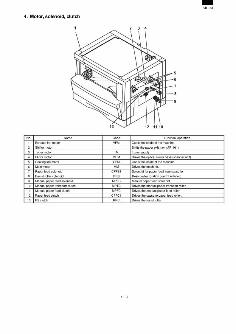
4. Motor, solenoid, clutch
No. Name Code Function, operation
1 Exhaust fan motor VFM Cools the inside of the machine.
2 Shifter motor Shifts the paper exit tray. (AR-161)
3 Toner motor TM Toner supply
4 Mirror motor MRM Drives the optical mirror base (scanner unit).
5 Cooling fan motor CFM Cools the inside of the machine.
6 Main motor MM Drives the machine.
7 Paper feed solenoid CPFS1 Solenoid for paper feed from cassette
8 Resist roller solenoid RRS Resist roller rotation control solenoid9 Manual paper feed solenoid MPFS Manual paper feed solenoid
10 Manual paper transport clutch MPTC Drives the manual paper transport roller.
11 Manual paper feed clutch MPFC Drives the manual paper feed roller.
12 Paper feed clutch CPFC1 Drives the cassette paper feed roller.
13 PS clutch RRC Drives the resist roller
1 4
7
6
5
1 1 1 01 2
9
8
1 3
2 3
AR-161
4 – 3
7/27/2019 Sharp Ar 160 & 161ar-161 Service Manual
http://slidepdf.com/reader/full/sharp-ar-160-161ar-161-service-manual 18/67
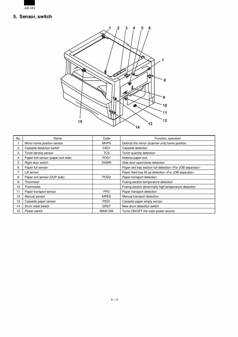
5. Sensor, switch
No. Name Code Function, operation
1 Mirror home position sensor MHPS Detects the mirror (scanner unit) home position.
2 Cassette detection switch CSD1 Cassette detection
3 Toner density sensor TCS Toner quantity detection
4 Paper exit sensor (paper exit side) POD1 Detects paper exit.
5 Right door switch DSWR Side door open/close detection
6 Paper full sensor Paper exit tray section full detection <For JOB separator>
7 Lift sensor Paper feed tray lift up detection <For JOB separator>
8 Paper exit sensor (DUP side) POD2 Paper transport detection9 Thermistor Fusing section temperature detection
10 Thermostat Fusing section abnormally high temperature detection
11 Paper transport sensor PPD Paper transport detection
12 Manual sensor MPED Manual transport detection
13 Cassette paper sensor PED1 Cassette paper empty sensor
14 Drum reset switch DRST New drum detection switch
15 Power switch MAIN SW Turns ON/OFF the main power source.
1 2 3 4
7
65
8
9
1 0
1 1
1 21 3
1 4
1 5
AR-161
4 – 4
7/27/2019 Sharp Ar 160 & 161ar-161 Service Manual
http://slidepdf.com/reader/full/sharp-ar-160-161ar-161-service-manual 19/67
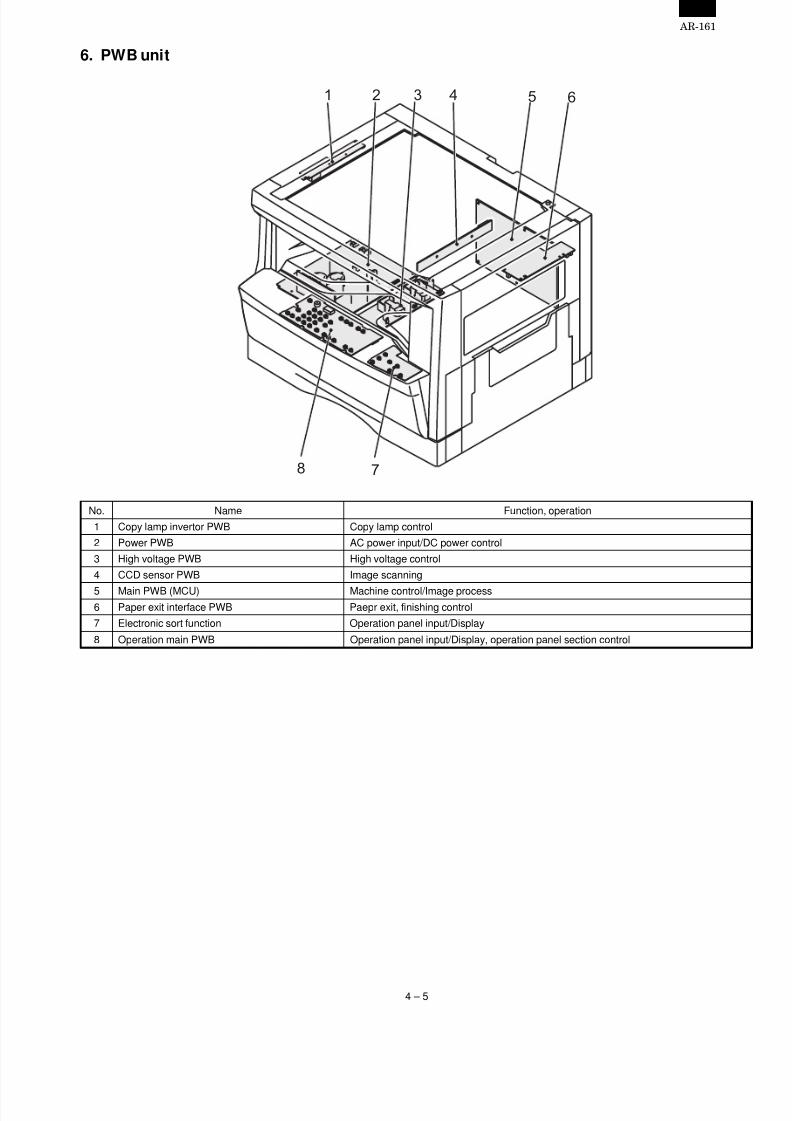
6. PWB unit
No. Name Function, operation
1 Copy lamp invertor PWB Copy lamp control
2 Power PWB AC power input/DC power control
3 High voltage PWB High voltage control
4 CCD sensor PWB Image scanning
5 Main PWB (MCU) Machine control/Image process6 Paper exit interface PWB Paepr exit, finishing control
7 Electronic sort function Operation panel input/Display
8 Operation main PWB Operation panel input/Display, operation panel section control
1 2 3 4
8 7
65
AR-161
4 – 5

7/27/2019 Sharp Ar 160 & 161ar-161 Service Manual
http://slidepdf.com/reader/full/sharp-ar-160-161ar-161-service-manual 20/67
7. Cross sectional view
No. Name Function/Operation
1 Copy lamp Image radiation lamp
2 Copy lamp unit Operates in synchronization with No. 2/3 mirror unit to radiate documents sequentially.
3 LSU unit Converts image signals into laser beams to write on the drum.
4 Lens unit Reads images with the lens and the CCD.
5 MC holder unit Supplies negative charges evenly on the drum.6 Paper exit roller Used to discharge paper.
7 Transport roller Used to transport paper.
8 Upper heat roller Fuses toner on paper (with the teflon roller).
9 Lower heat roller Fuses toner on paper (with the silicon rubber roller).
10 Drum unit Forms images.
11 Transfer charger unit Transfer images (on the drum) onto paper.
12 Resist roller Takes synchronization between the paper lead edge and the image lead edge.
13 Manual paper feed tray Manual paper feed tray
14 Manual paper feed roller Picks up paper in manual paper feed.
15 Manual transport roller Transports paper from the manual paper feed port.
16 Paper feed roller (semi-circular roller) Picks up paper from the cassette.
17 MG roller Puts toner on the OPC drum.
18 No. 2/3 mirror unit Reflects the images from the copy lamp unit to the lens unit.
19 Waste toner transport roller Transports waste toner to the waste toner box.
1 2 3 4 5
6
7
8
9
1 0
1 1
1 2
1 31 41 51 6
1 9
1 7
1 8
AR-161
4 – 6

7/27/2019 Sharp Ar 160 & 161ar-161 Service Manual
http://slidepdf.com/reader/full/sharp-ar-160-161ar-161-service-manual 21/67
[5] UNPACKING ANDINSTALLATION
1. Installation of machine
A. Installing conditionsSince the machine performance is largely affected by the installingplace conditions, take enough considerations on the following items
1) Environment
• Avoid installation at a place with direct sunlight. If not, the plasticparts may be deformed.
• Avoid installation near a heater, a humidifier, or an air conditionerwhere humidity and temperature are extremely high or low. If not,paper may be dampened and dew is formed inside the machine,causing paper jam or dirty copies.
• Avoid installation at a dusty place. If dust enters the machine, dirtycopy or a trouble may be caused.
• Avoid installation at a place with vibrations. If not, a machinetrouble may be caused.
• Avoid installation at a poorly ventilated place.
• Avoid installation at a place that is filled with ammonium gas. If thecopier is installed near a diazo-copier, dirty copies may beresulted.
2) Space around the copier
• Allow a space of more than between the copier rear side and thewall.
3) Power source
• Use an exclusive-use power outlet of 15A and 100V or more. If thepower plug of this machine is inserted into a power outlet com-monly used with other illumination units, flickers of the lamp maybe resulted. Use a power outlet which is not used commonly withany illumination units.
• Avoid complex wiring.
4) Grounding wire connection.
• To avoid danger, be sure to connect a grounding wire. If no grouning wire is connected and a leakage occurs, a fire or an electric
shock may be resulted.
2. Removal of protective material andfixing screw
1) Remove all tapes and protective material.
• Remove all tapes, then open the document cover and removethe protective material of sheet shape
2) Remove the fixing screw.
• Use a coin to remove the fixing screw.
• The fixing screw is required when transporting the machine.Keep it in the tray. (Refer to the later description.)
3. Installation of developing cartridge
1) Open the manual paper feed tray.
2) Lift the knob and slide the side cover gently.
3) Open the front cover.
• Hold the both edge gently and open the front cover.
4) Remove the screw from the upper section of the insertion port ofthe developer cartridge.
5) Shake a new developer cartridge a few times as shown.
• Shake it horizontally as shown with the arrow.
AR-161
5 – 1

7/27/2019 Sharp Ar 160 & 161ar-161 Service Manual
http://slidepdf.com/reader/full/sharp-ar-160-161ar-161-service-manual 22/67
6) Remove the pawls (3 positions) of the protective cover at therearside.
7) Remove the protective cover.
• Pull the cover in the arrow direction to remove.
8) Insert the developer cartridge.• Gently insert the developer cartridge along the guide until itlocks.
9) Fix the developer cartridge with the fixing screw which is packed
together with the machine.
10) Close the front cover A, then close the side cover B.
• When closing the front cover, gently press the both sides.
• When closing the side cover, hold the knob.
• When closing the covers, be sure to close the front cover first,then close the side cover. If closed in a wrong sequence, thecovers may be broken.
4. Removal and storage of fixing screw
1) Lift the knob and gently pull out the tray.
2) Hold the paper pressure plate and turn the fixing screw in thearrow direction.
3) Store the fixing pin and the fixing screw in the tray.
• Store the fixing screw which was removed in the above proce-dure 2 and the fixing screw which was removed in procedure 2of 2.
• Removal of protective material and fixing screw in the storageplace in the tray.
A
B
Pressure
plate
lock
Screw
AR-161
5 – 2

7/27/2019 Sharp Ar 160 & 161ar-161 Service Manual
http://slidepdf.com/reader/full/sharp-ar-160-161ar-161-service-manual 23/67
5. Changing the copy paper size in the tray
1) Gently lift and pull out the paper tray until it stops.
2) Push the pressure plate down until it locks in place.
3) Squeeze the lock lever of the front guide and slide the front guideto match the width of the paper.
4) Move the left guide to the appropriate slot as marked on the tray.
• When using 11" ×17" copy paper, store the left guide in the slotat the left front of the paper tray.
5) Load copy paper into the tray.
6) Place the paper size plate in the front of the paper tray.
• The paper size indication which shows through the slot on thefront of the copier should match the selected paper size.
7) Push the paper tray firmly back into the copier.
8) To set the selected paper size, press and hold down the PAPERSIZE ENTER key. The selected paper feed location indicator andthe corresponding paper size (which has been set) indicator willblink. All other indicators will go out.
• For paper size setting, ensure that the COPY mode has been
selected. However, if printer or facsimile output is being per-formed, paper size setting cannot be made even in the COPYmode.
9) Use the TRAY SELECT key to select the paper tray of which thepaper size has been changed.
• Each time the TRAY SELECT key is pressed, a paper tray isindicated with a blinking paper feed location indicator. If anoptional paper feed unit is not installed, this operation is notneeded.
10) Use the ORIGINAL SIZE ENTER key to select the paper sizewhich is set.
• Each time the ORIGINAL SIZE ENTER key is pressed, apaper size will be indicated with a blinking paper size in-dicator.
11) Press the START key and then the PAPER SIZE ENTER key.
• To change the paper size setting of another tray, repeat steps9 to 10 after pressing the START key.
Front guide
Left guide
AR-161
5 – 3

7/27/2019 Sharp Ar 160 & 161ar-161 Service Manual
http://slidepdf.com/reader/full/sharp-ar-160-161ar-161-service-manual 24/67
[6] OPERATIONAL DESCRIPTIONS
1. Outline of operation
The outline of operation is described referring to the basic configura-tion.
(Basic configuration)
Outline of copy operation
A. Setting conditions: Operation panel• Set copy conditions such as the copy quantity and the copy den-
sity with the operation section, and press the START key. Theinformation on copy conditions is sent to the MCU.
B. Image scanning: Scanner section
• When the START key is pressed, the scanner section starts scan-ning of images.The light from the copy lamp is reflected by thedocument and passed through the lens to the CCD.
C. Photo signal/Electric signal conversion:Scanner section
• The image is converted into electrical signals by the CCD circuitand passed to the MCU.
D. Image process: MCU
• The document image signal sent from the CCD circuit is processedunder the revised conditions and sent to the LSU (laser unit) asprint data.
E. Electric signal/Photo signal (laser beam)conversion: LSU
• The LSU emits laser beams according to the print data. (Electricalsignals are converted into photo signals.)
• The laser beams are radiated through the polygon mirror andvarious lenses to the OPC drum.
F. Printing: Process section
• Electrostatic latent images are formed on the OPC drum accordingto the laser beams, and the latent images are developed to bevisible images (toner images).
• Meanwhile the paper is fed to the image transfer section insynchronization with the image lead edge.
• The toner image is transferred on the paper.
G. Fusing: Fusing section• Heat and a pressure are applied to the toner image on the copy
paper to fuse the image on the paper.
2. Scanner section
A. Scan process
The scanner has sensors that are arranged in a line. These sensorsscan a certain area of a document at a time and deliver outputssequentially. When the line is finished, the next line is scanned, and
this procedure is repeated. The figure below shows the case wherean image which is scanned is shown with solid lines.
The direction of this line is called main scanning direction, and thescanning direction sub scanning direction. In the figure above, oneline is divided into 5 sections. Actually, however, one line is dividedinto thousands of sections. For scanning, the light receiving elementcalled CCD is used.
The basic resolution indicates the scanner capacity. The basic resolu-tion is expressed in dpi (dot/inch) which shows the number of lightemitting elements per inch on the document.The basic resolution of this machine is 400dpi.In the sub scanning direction, at the same time, the motor that drivesthe optical system is controlled to scan the image at the basic resolu-tion.
Operationsection
Scanner section
CCD
MCU (Main control/image process section)
Laser beamPaper exit
Fusing section
Paper transport section
Manual paperfeed section
Cassette paperfeed section
Printer section
LSU (Laser unit)Laser diode, Polygon mirror lens
Process section
1
2
3
4
5
5 4 3 2 1
Sub scanning direction
Sensor scanning area
Main
scanning
direction
To MCU PWB
AR-161
6 – 1

7/27/2019 Sharp Ar 160 & 161ar-161 Service Manual
http://slidepdf.com/reader/full/sharp-ar-160-161ar-161-service-manual 25/67
B. Basic structure of scanner section
1 Copy lamp (Xenon lamp) Generate photo energy to scan documents.
2 Reflector (Converging plate) Collects l ight emitted from the copy lamp and radiate the document.
3 No. 1 mirror Refracts the reflection light from the document to No. 2 mirror.
4 No. 2 mirror Refracts the reflection light from No. 1 mirror.
5 No. 3 mirror Refracts the reflection light from No. 2 mirror.
6 Lens Converges reflected light from the document to form images on the CCD element.
7 No. 2/3 mirror unit Includes No. 2/3 mirror. Driven in synchronization with the copy lamp unit.
8 Copy lamp unit Includes the copy lamp, the reflector, and No. 1 mirror. Driven in synchronization with No. 2/3
mirror unit by the mirror motor.9 CCD PWB Reflected light (image) formed on the CCD is converted into electrical signals (analog signals)
then into digital signals and sent to the MCU.
10 Mirror motor Drives the copy lamp unit and No. 2/3 mirror unit according to the scanning speed.
11 MHPS (Mirror home position sensor) Detects the home position of No. 2/3 mirror unit.
12 Reference white plate Reference white sheet for scanning documents. The reference line of magnification ratioadjustment during SIM is also drawn.
13 OC glass Glass table to put a document on it.
The light from the light source (Xenon lamp) is reflected by a document and passed through three mirrors and reduction lenses to the CCD element(image sensor) where images are formed. This system is known as the reduction image sensor system. Photo energy on the CCD element isconverted into electrical signals (analog signals). (Photo-electric conversion). The output signals (analog signals) are converted into digital signals(A/D conversion) and passed to the MCU (main control/image process section). The resolution at that time is 400dpi. The mirror unit in the scannersection is driven by the mirror motor. The MHPS is provided to detect the home position of the copy lamp unit.
3. Process section
A. Basic structure
1 Main charger unit Charges the OPC drum.
2 Cleaning blade Collects waste toner on the OPCdrum.
3 OPC drum Images are formed by laser beamselectrically, and toner is attached tothe image.
4 Transfer unit Toner on the OPC drum is transferredto the print paper by the potentialdifference.
5 Resist roller Makes synchronization between thepaper and the print image.
6 MG roller Magnetic brush is formed bydeveloper to put toner on the OPCdrum.
7 (Laser beam) Forms images on the OPC drum.
AR-161
6 – 2
7/27/2019 Sharp Ar 160 & 161ar-161 Service Manual
http://slidepdf.com/reader/full/sharp-ar-160-161ar-161-service-manual 26/67
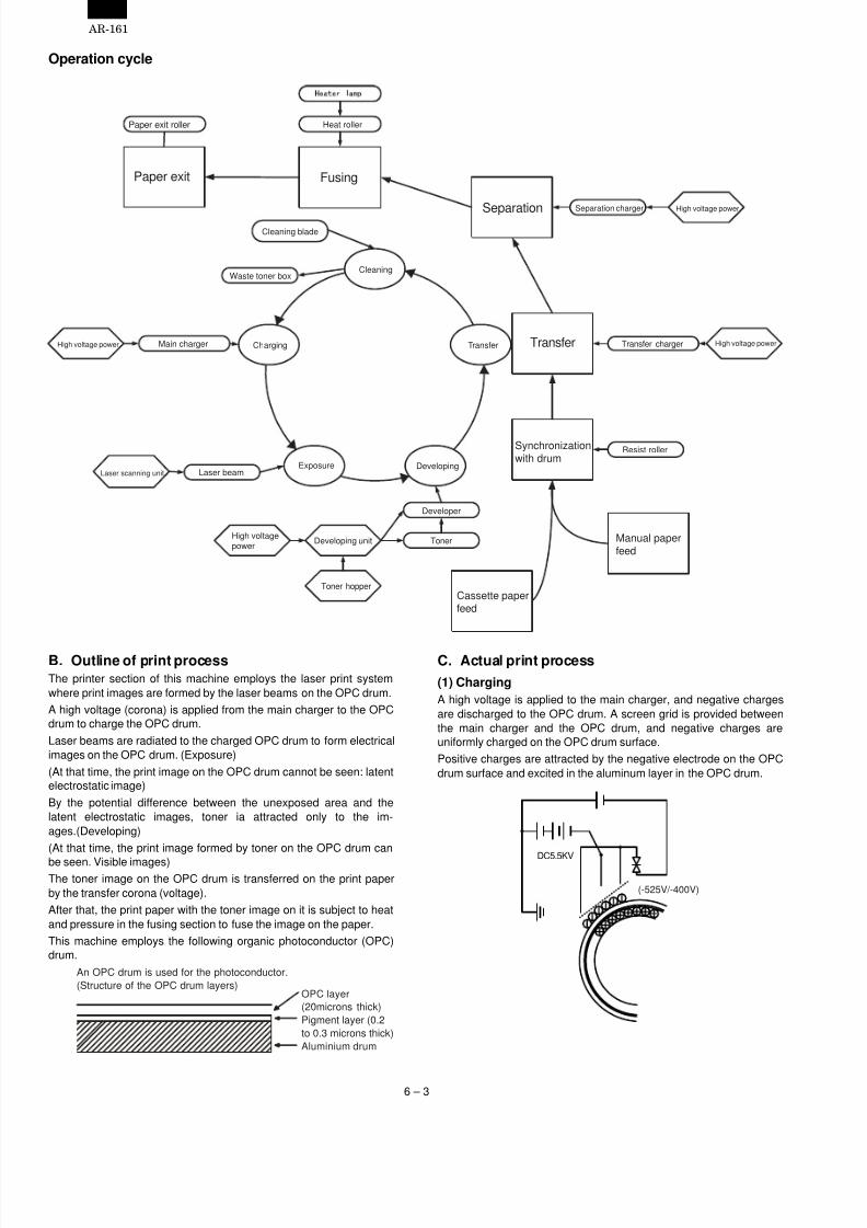
Operation cycle
B. Outline of print processThe printer section of this machine employs the laser print systemwhere print images are formed by the laser beams on the OPC drum.
A high voltage (corona) is applied from the main charger to the OPCdrum to charge the OPC drum.
Laser beams are radiated to the charged OPC drum to form electricalimages on the OPC drum. (Exposure)
(At that time, the print image on the OPC drum cannot be seen: latentelectrostatic image)
By the potential difference between the unexposed area and thelatent electrostatic images, toner ia attracted only to the im-ages.(Developing)
(At that time, the print image formed by toner on the OPC drum can
be seen. Visible images)The toner image on the OPC drum is transferred on the print paperby the transfer corona (voltage).
After that, the print paper with the toner image on it is subject to heatand pressure in the fusing section to fuse the image on the paper.
This machine employs the following organic photoconductor (OPC)drum.
C. Actual print process
(1) Charging
A high voltage is applied to the main charger, and negative chargesare discharged to the OPC drum. A screen grid is provided betweenthe main charger and the OPC drum, and negative charges areuniformly charged on the OPC drum surface.
Positive charges are attracted by the negative electrode on the OPCdrum surface and excited in the aluminum layer in the OPC drum.
Paper exit roller
Paper exit
Heat roller
Fusing
Cleaning blade
Waste toner box
Separation
Cleaning
Separation charger High voltage power
High voltage power Main charger Charging Transfer Transfer Transfer charger High voltage power
Laser scanning unit Laser beamExposure Developing
Synchronizationwith drum
Resist roller
High voltagepower
Developing unit
Toner hopper
Developer
Toner
Cassette paperfeed
Manual paperfeed
(20microns thick)
Aluminium drum
Pigment layer (0.2
to 0.3 microns thick)
An OPC drum is used for the photoconductor.
(Structure of the OPC drum layers)OPC layer
DC5.5KV
(-525V/-400V)
AR-161
6 – 3
7/27/2019 Sharp Ar 160 & 161ar-161 Service Manual
http://slidepdf.com/reader/full/sharp-ar-160-161ar-161-service-manual 27/67
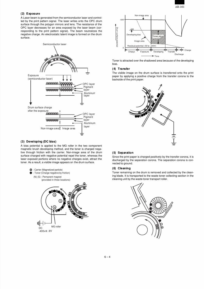
(2) Exposure
A Laser beam is generated from the semiconductor laser and control-led by the print pattern signal. The laser writes onto the OPC drumsurface through the polygon mirrors and lens. The resistance of theOPC layer decreases for an area exposed by the laser beam (cor-responding to the print pattern signal). The beam neutralizes thenegative charge. An electrostatic latent image is formed on the drumsurface.
(3) Developing (DC bias)
A bias potential is applied to the MG roller in the two componentmagnetic brush developing method, and the toner is charged nega-
tive through friction with the carrier. Non-image area of the drumsurface charged with negative potential repel the toner, whereas thelaser exposed portions where no negative charges exist, attract thetoner. As a result, a visible image appears on the drum surface.
Toner is attracted over the shadowed area because of the developingbias.
(4) Transfer
The visible image on the drum surface is transferred onto the printpaper by applying a positive charge from the transfer corona to thebackside of the print paper.
(5) SeparationSince the print paper is charged positively by the transfer corona, it isdischarged by the separation corona. The separation corona is con-nected to ground.
(6) Cleaning
Toner remaining on the drum is removed and collected by the clean-ing blade. It is transported to the waste toner collecting section in thecleaning unit by the waste toner transport roller.
OPC layerPigmentlayer
Aluminum
OPC layerPigmentlayer
Aluminum
layer
Drum surface charge
sfter the exposure
Non-image area Image area
Semiconductor laser
Exposure
(semiconductor laser)
layer
S
N
N
MG roller
DC-400v -8V
: Carrier (Magnetized particle)
: Toner (Charge negative by friction)
(N) (S) : Pemanent magnet(provided in three locations)
-600
0
Toner attract
potential
D r um s ur f a c e p o t en t i al
Non-image area
Developing bias
Image area
Residual potential (-50 to - 100V)
Charge Exposure Developing Transfer
Discharge
Charge
Time
-400
AR-161
6 – 4
7/27/2019 Sharp Ar 160 & 161ar-161 Service Manual
http://slidepdf.com/reader/full/sharp-ar-160-161ar-161-service-manual 28/67
(7) Optical discharge (Semiconductor laser)
Before the drum rotation is stopped, the semiconductor laser isradiated onto the drum to reduce the electrical resistance in the OPClayer and eliminate residual charge, providing a uniform state to thedrum surface for the next page to be printed.When the electrical resistance is reduced, positive charges on thealuminum layer are moved and neutralized with negative charges onthe OPC layer.
a. Charge by the Scorotron charger
<1> Function
The Scorotron charger functions to maintain the surface potential ofthe drum even at all times which. It is used to control the surfacepotential regardless of the charge characteristics of the photoconduc-tor.
<2> Basic function
A screen grid is placed between the saw tooth and the photoconduc-tor. A stable voltage is added to the screen grid to maintain thecorona current on the photoconductor. As the photoconductor ischarged by the saw tooth from the main corona unit, the surfacepotential increases. This increases the current flowing through thescreen grid. When the photoconductor potential nears the grid poten-tial, the current turns to flow to the grid so that the photoconductorpotential can be maintained at a stable level.
b. Process controlling
<1> Function
The print pattern signal is converted into an invisible image by thesemiconductor laser using negative to positive (reversible) developingmethod. Therefore, if the developing bias is added before the drum ischarged, toner is attracted onto the drum. If the developing bias is not
added when the drum is charged, the carrier is attracted to the drumbecause of the strong electrostatic force of the drum.To avoid this, the process is controlled by adjusting the drum poten-tial and the grid potential of the Scorotron charger.
<2> Basic function
Voltage added to the screen grid can be selected, high and low.To make it easily understood, the figure below shows voltage transi-tion at the developer unit.
<3> Start
1) Because the grid potential is at a low level, the drum potential is atabout –400V. (Carrier may not be attracted though the carrier ispulled towards the drum by the electrostatic force of –400V.)
2) Developing bias (–400V) is applied when the photoconductorpotential is switched from LOW to HIGH.
3) Once developing bias (–400V) is applied and the photo conductorpotential rises to HIGH, toner will not be attracted to the drum.
<4> Stop
The reverse sequence takes place.
c. Retaining developing bias at an abnormal occurrence
<1> Function
The developing bias will be lost if the power supply was removedduring print process. In this event, the drum potential slightly abatesand the carrier makes deposits on the drum because of strong staticpower. To prevent this, the machine incorporates a function to retainthe developing bias for a certain period and decrease the voltagegradually against possible power loss.
<2> Basic function
Normally, the developing bias voltage is retained for a certain timebefore the drum comes to a complete stop if the machine should stopbefore completing the normal print cycle. The developing bias can beadded before resuming the operation after an abnormal interruption.Therefore, carrier will not make a deposit on the drum surface.
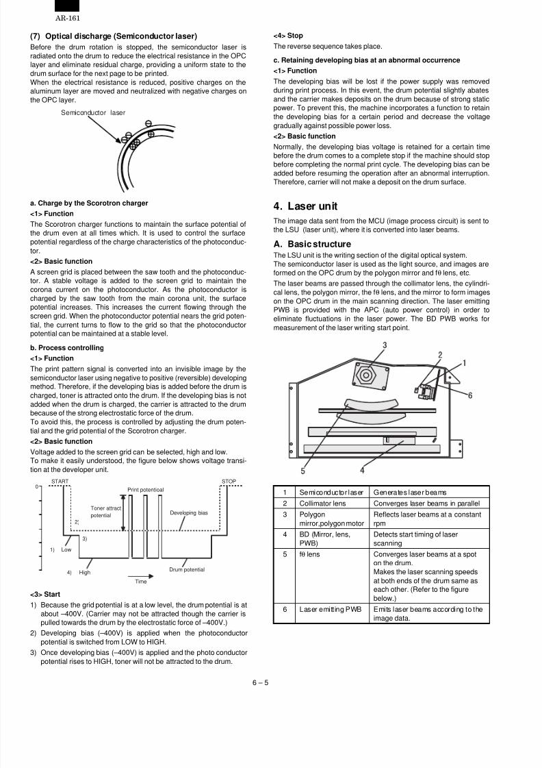
4. Laser unit
The image data sent from the MCU (image process circuit) is sent tothe LSU (laser unit), where it is converted into laser beams.
A. Basic structureThe LSU unit is the writing section of the digital optical system.The semiconductor laser is used as the light source, and images areformed on the OPC drum by the polygon mirror and fθ lens, etc.The laser beams are passed through the collimator lens, the cylindri-cal lens, the polygon mirror, the fθ lens, and the mirror to form imageson the OPC drum in the main scanning direction. The laser emittingPWB is provided with the APC (auto power control) in order toeliminate fluctuations in the laser power. The BD PWB works formeasurement of the laser writing start point.
1 Semiconductor laser Generates laser beams
2 Collimator lens Converges laser beams in parallel
3 Polygonmirror,polygon motor
Reflects laser beams at a constantrpm
4 BD (Mirror, lens,PWB)
Detects start timing of laserscanning
5 fθ lens Converges laser beams at a spoton the drum.Makes the laser scanning speedsat both ends of the drum same aseach other. (Refer to the figurebelow.)
6 Laser emitting PWB Emits laser beams according to theimage data.
Semiconductor laser
0START STOP
Print potentioal
Toner attract
potential
2)
3)
1) Low
4) HighDrum potential
Developing bias
Time
AR-161
6 – 5

7/27/2019 Sharp Ar 160 & 161ar-161 Service Manual
http://slidepdf.com/reader/full/sharp-ar-160-161ar-161-service-manual 29/67
Makes the laser scanning speeds at both ends of the drum same aseach other.
B. Laser beam path
a ≠ b ≠ c
a b c
d = e = f
d e f
5. Paper feed section
A. Basic structure
1 No. 1 cassette paper feed roller (Semi-circular roller) Picks up paper from No. 1 cassette.2 Main motor Drives the process section and the paper transport section.3 No. 1 cassette paper feed solenoid Rotates and controls No. 1 cassette paper feed roller.4 No. 1 cassette paper feed roller clutch Drives No. 1 cassette paper feed roller.5 Manual paper feed roller Picks up paper from the manual paper feed tray.6 Manual paper transport roller Transport paper which was picked up from the manual paper feed tray.7 Manual paper feed roller clutch Drives the manual paper feed roller.8 Manual paper transport roller clutch Drives the manual paper transport roller.9 Manual paper feed roller solenoid Rotates and controls the manual paper feed roller.10 Manual paper transport roller solenoid Rotates and controls the manual paper transport roller.11 Resist roller Takes synchronization between the paper lead edge and the image lead edge.
12 Resist roller clutch Drives the resist roller.13 Resist roller solenoid Rotates and controls the resist roller.
B. Brief descriptions of operationsThis machine allows two ways of paper feed system: cassette paperfeed and manual paper feed.The cassette of universal type is employed to hold 250 sheets. Thefront loading system allows to attach or detach the cassette from thefront of the machine.Paper size can be selected by the user.
Paper size detection is set by the software. (User setting is allowed.)By installing the optional 1-step paper feed unit or the multi-steppaper feed unit, the capacity of paper can be increased.
(1) Cassette paper feed operation
Select the cassette and press the START button, and the paper feedroller solenoid will be turned on and the paper feed clutch will bereleased.The drive power of the main motor is transmitted through the paperfeed roller clutch to the paper feed roller, rotating the paper feed rollerand feeding paper.
AR-161
6 – 6

7/27/2019 Sharp Ar 160 & 161ar-161 Service Manual
http://slidepdf.com/reader/full/sharp-ar-160-161ar-161-service-manual 30/67
(2) Manual paper feed tray operation
Select the manual paper feed tray and press the START button, andthe manual paper feed roller will be turned on to bring the paper feedroller in contact with paper and lift the shutter simultaneously.The drive power of the main motor is transmitted through the manualpaper feed roller clutch to the manual paper feed roller, rotating themanual paper feed roller and feeding paper.
(3) Resist roller
In order to make synchronization between the paper lead edge fedfrom the paper feed port and the image lead edge, the roller is kept
stationary for a certain time after the paper reaches at the roller towarp the paper a little.When the paper is warped to a certain level, the resist roller solenoidis turned on to release the resist roller clutch.The drive power of the main motor is transmitted through the resistroller clutch to the resist roller, rotating the resist roller and feedingpaper.
6. Fusing section
A. Basic composition
(Top view)
1 Before-fusingpaper guide
Guides the paper transported fromthe process section to the fusing unit.
2 Upper heat roller Applies heat and pressure to the
paper to fuse.3 Thermistor Detects the surface temperature of
the upper heat roller.4 Thermostat Stops power supply to the heat roller
in case of an abnormally hightemperature of the heat roller.
5 Separation pawl Separates the print paper from theupper heat roller.
6 POD1 Detects that the paper has beentransported from the fusing section.
7 Heater lamp Heats the heat roller.8 Lower heat roller Applies a pressure to the paper
together with the upper heat roller.
B. Heat rollerA pressure roller is used for the heat roller and a silicone rubber rolleris used for the lower heat roller for better toner fusing performanceand paper separation.
C. Separator pawlFour separator pawls are used on the upper heat roller. Theseparator pawls are teflon coated to reduce friction with the roller andprevent a smear on the paper caused by the separator pawl.
D. Thermal control
1) The heater lamp, thermistor, main PWB, DC power supply PWB,and triac within the power supply unit are used to control thetemperature in the fuser unit.To prevent against abnormally hightemperature in the fuser unit, a thermostat is used for safety pur-poses.
2) The surface temperature of the upper heat roller is set to 180°C ~195°C. The surface temperature during the power save mode is
set to 100°C.3) The self-check function comes active when one of the following
malfunctions occurs, and an "H" is displayed on the copy quantitydisplay.
Fusing temperature error value
H4 (Low temperature error)
• During machine operationThe case where the fusing temperature (thermistor outputvalue) does not reach 155°C within 55 sec from lighting of theheater lamp. (If the toner motor rotates for 10 sec or morecontinuously when starting the machine, the case where thefusing temperature does not reach 155°C within 60 sec.)
• During printingWhen the fusing temperature (thermistor output value) falls
below 145°C.H3 (High temperature error)
Fusing temperature (thermistor output value) of about 220 to240°C (varies depending on the resistance.)
E. Fusing resistor
(1) Fusing resistor
Since the upper heat roller is conductive when copy paper is highlymoistured and the distance between the transfer unit and the fusingunit is short, the transfer current leaks through the copy paper, theupper heat roller and the discharging brush.To prevent against this, a resistor of 150MOhm is provided betweenthe frame and the discharge brush to minimize leak current andimprove transfer efficiency.
Safety device(thermal breaker, thermalfuse)
Triac (in thepower supply unit)
Heated by theheater lamp.(950W )
The surface temperatureof the upper heat rolleris sensed by the thermistor.
Level of the thermistor iscontrolled by the main PWB.
With the signal from themain PWB, the triac iscontrolled on and off.(power supply PWB )
AR-161
6 – 7
7/27/2019 Sharp Ar 160 & 161ar-161 Service Manual
http://slidepdf.com/reader/full/sharp-ar-160-161ar-161-service-manual 31/67
[7] ADJUSTMENTS
1. Adjustment item list
Section Adjustment item Adjustment procedure/SIM No.
A Process section (1) Developing doctor gap adjustment Developing doctor gap adjustment
(2) MG roller main pole position adjustment MG roller main pole position adjustment
(3) Developing bias voltage output adjustment SIM 8-1
(4) Main charger voltage output adjustment SIM 8-2/SIM 8-3
(5) Transfer charger current adjustment SIM 8-6B Mechanism section (1) Image position adjustment SIM 50-1/SIM 50-10
(2) Main scanning direction (FR direction)distortion balance adjustment
No. 2/3 mirror base unit installing positionadjustment
Copy lamp unit installing position adjustment
(3) Main scanning direction (FR direction)distortion adjustment
F rail height adjustment
(4) Sub scanning direction (scanning direction)distortion adjustment
Winding pulley position adjustment
(5) Main scanning direction (FR direction)magnification ratio adjustment
SIM 48-1
(6) Sub scanning direction (scanning direction)magnification ratio adjustment
a OC mode in copying (SIM 48-2)
b SPF mode in copying (SIM 48-5)
c OC mode in FAX (SIM 48-6)d SPF mode in FAX (SIM 48-7)
(7) Off center adjustment a OC mode (SIM 50-13)
b SPF mode (SIM 50-16)
(8) Document size detection sensor SIM 41-2
C Image density adjustment (1) Copy mode SIM 46-1
2. Copier adjustment
A. Process section
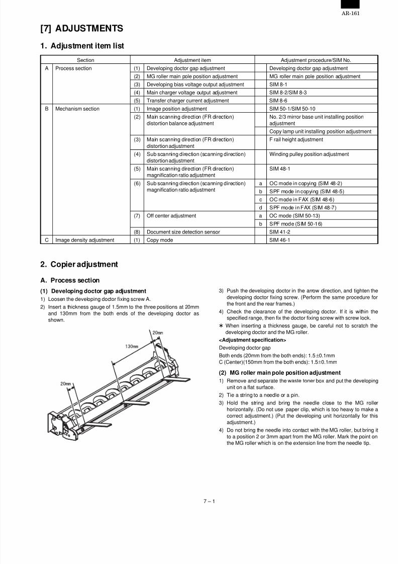
(1) Developing doctor gap adjustment
1) Loosen the developing doctor fixing screw A.2) Insert a thickness gauge of 1.5mm to the three positions at 20mm
and 130mm from the both ends of the developing doctor asshown.
3) Push the developing doctor in the arrow direction, and tighten the
developing doctor fixing screw. (Perform the same procedure forthe front and the rear frames.)
4) Check the clearance of the developing doctor. If it is within thespecified range, then fix the doctor fixing screw with screw lock.
* When inserting a thickness gauge, be careful not to scratch thedeveloping doctor and the MG roller.
<Adjustment specification>
Developing doctor gap
Both ends (20mm from the both ends): 1.5±0.1mmC (Center)(150mm from the both ends): 1.5±0.1mm
(2) MG roller main pole position adjustment
1) Remove and separate the waste toner box and put the developingunit on a flat surface.
2) Tie a string to a needle or a pin.3) Hold the string and bring the needle close to the MG roller
horizontally. (Do not use paper clip, which is too heavy to make acorrect adjustment.) (Put the developing unit horizontally for thisadjustment.)
4) Do not bring the needle into contact with the MG roller, but bring itto a position 2 or 3mm apart from the MG roller. Mark the point onthe MG roller which is on the extension line from the needle tip.
AR-161
7 – 1

7/27/2019 Sharp Ar 160 & 161ar-161 Service Manual
http://slidepdf.com/reader/full/sharp-ar-160-161ar-161-service-manual 32/67
5) Measure the distance from the marking position to the top of thedoctor plate of the developing unit to insure that it is 18mm.If the distance is not within the specified range, loosen the fixingscrew A of the main pole adjustment plate, and move the adjust-ment plate in the arrow direction to adjust.
(3) Developing bias voltage adjustment (SIM 8-1)
Note: • Use a digital multi-meter with an internal resistance of
10MΩ or more.1) Set the digital multi-meter range to DC700V.
2) Put the test rod of the digital multi-meter on the developing biasvoltage output check pin.
3) Execute SIM 8-1. (The developing bias voltage is outputted for 30sec.)
4) Adjust the adjustment volume VR31 so that the output voltage iswithin the specified range shown below.
<Adjustment specification>
Mode Specification SIM
Developing bias voltage DC-400±8V SIM 8-1 VR31
(4) Grid bias voltage adjustment (SIM 8-2, SIM 8-3)
Note: • Use a digital multi-meter with an internal resistance of10MΩ or more.
• First adjust the grid LOW output, then adjust the grid HIGHvoltage.
1) Set the digital multi-meter range to DC700V.
2) Put the test rod of the digital multi-meter on the grid bias voltageoutput check pin.
3) Execute SIM 8-3. (The grid bias voltage is outputted in the gridbias LOW output mode for 30 sec.)
4) Adjust the adjustment volume VR52 so that the output voltage iswithin the specified range shown below.
5) Execute SIM 8-2. (The grid bias voltage is outputted in the gridbias HIGH output mode for 30 sec.)
6) Adjust the adjustment volume VR51 so that the output voltage iswithin the specified range shown below.
<Adjustment specification>
Mode Specification SIMGrid bias LOW DC-400±20V SIM 8-3 VR52Grid bias HIGH DC-525±10V SIM 8-2 VR51
B. Mechanism section
(1) Image position adjustment (SIM 50-1/SIM 50-10)
a. Image lead edge position adjustment
1) Set a scale on the document table as shown below.
2) Make a copy.
3) Check the copy. If, necessary, perform the following adjustmentprocedure.
4) Execute SIM 50-1. Set AE (Laser radiation timing)/Lead edge void
AR-161
7 – 2

7/27/2019 Sharp Ar 160 & 161ar-161 Service Manual
http://slidepdf.com/reader/full/sharp-ar-160-161ar-161-service-manual 33/67
value to 0. Make a copy (100%) again.
5) Set the laser radiation timing (image loss amount). Measure R inthe figure below.
Laser radiation timing = R (mm) × 10
6) Set the lead edge void.
Measure H in the figure below.
Lead edge void = H(mm) × 10
7) Enter the set value and press the start key.
The correction value is stored and a copy is made.
<Adjustment specification>
Mode Specification SIM Set value Set rangeLaser radiationtiming
1 ~ 4mm SIM45-1
1 step:0.1mm shift
1 ~ 99
Lead edge voidadjustment
b. Rear edge void adjustment
1) Set a scale as shown in the figure below.
2) Set the document size to A4, and make two copies at 100%.
3) Check the second copy. If necessary, perform the following ad- justment procedure.
* The first copy does not show the void. Be sure to check thesecond copy.
4) Execute SIM 50-1 and set the density mode to AE + TEXT +PHOTO (Rear edge void).
The currently set adjustment value is displayed.
5) Enter the set value and press the start key.
The correction value is stored and a copy is made.
<Adjustment specification>
Mode Specification SIM Set value Set range
Rear edge void 4mm or less SIM50-1
1 step:0.1mm shift
1-99
c. Paper off center adjustment1) Execute SIM 50-1 and set the density mode of Manual (TEXT)
(Left edge void) to 0.
2) Set a test chart (UKOG-0089SCZZ) on the document table.
3) Select a paper feed port and make a copy.
Compare the copy and the test chart. If necessary, perform thefollowing adjustment procedure.
4) Execute SIM 50-10.
After completion of warmup, shading is performed and the cur-rently set off center adjustment value of each paper feed port isdisplayed.
5) Enter the set value and press the start key.
The correction value is stored and a copy is made.
<Adjustment specification>
Mode Specification SIM Set value Set range
Paperoff center
Single:Center ±2.0mm
SIM50-10
Add 1: 0.1mmshift to R side.Reduce 1:0.1mm shift toL side.
1 ~ 99
Duplex:Center ±2.5mm
d. Left edge void area adjustment
Note: Before performing this adjustment, be sure to check that thepaepr off center adjustment (SIM 50-10) is completed.
1) Set a test chart (UKOG-0089SCZZ) on the document table.
2) Select a paper feed port and make two copies.
Compare the second copy and the test chart. If necessary, per-form the following adjustment procedure.
* The first copy does not show the void. Be sure to check thesecond copy.
3) Execute SIM 50-1 and set the density mode to Manual (TEXT)(Left edge void).
The currently set adjustment value is displayed.(When the off center adjustment previously described is per-formed, "0" is displayed.)
4) Enter the set value and press the start key.
The correction value is stored and a copy is made.
<Adjustment specification>
Mode Specification SIM Set value Set range
Left edge void 1 ~ 4mm SIM50-1
1 step:0.1mm shift
1 ~ 99
* When the left edge void is set with the paper off center adjusted,the both edge void is automatically adjusted.
5mm
10mm
(Example)
Lead edge void H
Image loss R
A4(8.5" x 11")
Paper rear edge
Scale image
Paper rear edge
Void amount (Standard value: 0 4mm)
AR-161
7 – 3

7/27/2019 Sharp Ar 160 & 161ar-161 Service Manual
http://slidepdf.com/reader/full/sharp-ar-160-161ar-161-service-manual 34/67
(2) Main scanning direction (FR directional distortion
balance adjustment)
1) Remove the OC glass and the right cabinet.
2) Loosen the copy lamp unit wire fixing screw.
3) Manually turn the mirror base drive pulley and bring No. 2/3 mirrorbase unit into contact with the positioning plate.
At that time, if the front frame side and the rear frame side of No.2/3 mirror base unit are brought into contact with the positioningplate at the same time, the mirror base unit parallelism is proper.
If one of them is in contact with the positioning plate, perform theadjustment of 4).
4) Loosen the set screw of the scanner drive pulley which is not incontact with No. 2/3 mirror base unit positioning plate.
5) Without moving the scanner drive pulley shaft, manually turn thescanner drive pulley until the positioning plate is brought into con-tact with No. 2/3 mirror base unit, then fix the scanner drive pulley.
AR-161
7 – 4

7/27/2019 Sharp Ar 160 & 161ar-161 Service Manual
http://slidepdf.com/reader/full/sharp-ar-160-161ar-161-service-manual 35/67
6) Put No. 2/3 mirror base unit on the positioning plate again, pushthe projections on the front frame side and the rear frame side ofthe copy lamp unit to the corner frame, and tighten the wire fixingscrew.
(3) Main scanning direction (FR direction) distortion
adjustment
This adjustment must be performed in the following cases:
• When the mirror base drive wire is replaced.
• When the lamp unit, or No. 2/3 mirror holder is replaced.• When a copy as shown is made.
1) Set A3 (11" x 17") white paper on the original table as shownbelow.
2) Open the original cover and make a normal (100%) copy.
3) Measure the width of the black background at the lead edge andat the rear edge.
If the width (La) of the black background at the lead edge is equalthat (Lb) at the rear edge, there is no need to execute the follow-ing procedures of 4) ~ 7).
4) Loosen the mirror base drive pulley fixing screw on the front frameside or on the rear frame side.
• When La < LbTurn the mirror base drive pulley on the rear frame side in thearrow direction B. (Do not move the mirror base drive pulley
shaft.)• When La > Lb
Turn the mirror base drive pulley on the front frame side in thearrow direction A. (Do not move the mirror base drive pulleyshaft.)
5) Tighten the mirror base drive pulley fixing screw.
<Adjustment specification>
La = Lb
(4) Sub scanning direction (scanning direction)distortion adjustment
When there is no skew copy in the mirror base scanning direction andthere is no horizontal error (right angle to the scanning direction), the
adjustment can be made by adjusting the No. 2/3 mirror base unit railheight.
Before performing this adjustment, be sure to perform the horizontalimage distortion adjustment in the laser scanner section.
This adjustment must be performed in the following cases:
• When the mirror base wire is replaced.
• When the copy lamp unit or No. 2/3 mirror unit is replaced.
• When the mirror unit rail is replaced or moved.
• When a following copy is made.
LbLa
A
B
AR-161
7 – 5

7/27/2019 Sharp Ar 160 & 161ar-161 Service Manual
http://slidepdf.com/reader/full/sharp-ar-160-161ar-161-service-manual 36/67
1) Making of a test sheet
Make test sheet by drawing parallel lines at 10mm from the bothends of A3 (11" x 17") white paper as shown below. (These linesmust be correctly parallel to each other.)
2) Make a normal (100%) copy of the test sheet on A3 (11" x 17")paper. (Fit the paper edge with the glass holding plate edge.)
3) Measure the distances (La, Lb, Lc, Ld) at the four corners asshown below.
When La = Lb and Lc = Ld, no need to perform the procedures 4)and 5).
4) Move the mirror base B rail position up and down (in the arrowdirection) to adjust.
• When La > LbShift the mirror base B rail upward by the half of the differenceof La – Lb.
• When La < LbShift the mirror base B rail downward by the half of thedifference of Lb – La.
Example: When La = 12mm and Lb = 9mm, shift the mirrorbase B rail upward by 1.5mm.
• When Lc > LdShift the mirror base B rail downward by the half of the
difference of Lc – Ld.• When Lc < LdShift the mirror base B rail downward by the half of thedifference of Ld – Lc.
*When moving the mirror base rail, hold the mirror base rail withyour hand.
<Adjustment specification>
La = Lb, Lc = Ld
5) After completion of adjustment, manually turn the mirror basedrive pulley, scan the mirror base A and mirror base B fully, andcheck that the mirror bases are not in contact with each other.
* If the mirror base rail is moved extremely, the mirror base may bein contact with the frame or the original glass. Be careful to avoidthis.
(5) Main scanning direction (FR direction) magnification
ratio adjustment (SIM 48-1)
Note: Before performing this adjustment, be sure to check that theCCD unit is properly installed.
1) Put a scale on the original table as shown below.
2) Execute SIM 48-1.
3) After warmup, shading is performed and the current set value ofthe main scanning direction magnification ratio is displayed on thedisplay section in 2 digits.
4) Select the mode and press the start key again.
5) Auto correction mode (AE lamp ON)
The mirror unit moves to the shading position, and the referencewidth of the reference white plate is scanned, and the correctionvalue is automatically calculated from that scanned value.
The correction value is displayed and a copy is made.6) Compare the scale image and the actual scale.
If a fine adjustment is required, switch to the manual correctionmode with the magnification ratio display key and perform fineadjustment.
7) Manual correction mode (TEXT lamp ON)
Enter the set value and press the start key.
The set value is stored and a copy is made.
10mm
10mm
10mm
10mm
La
Lb Ld
Lc
AR-161
7 – 6
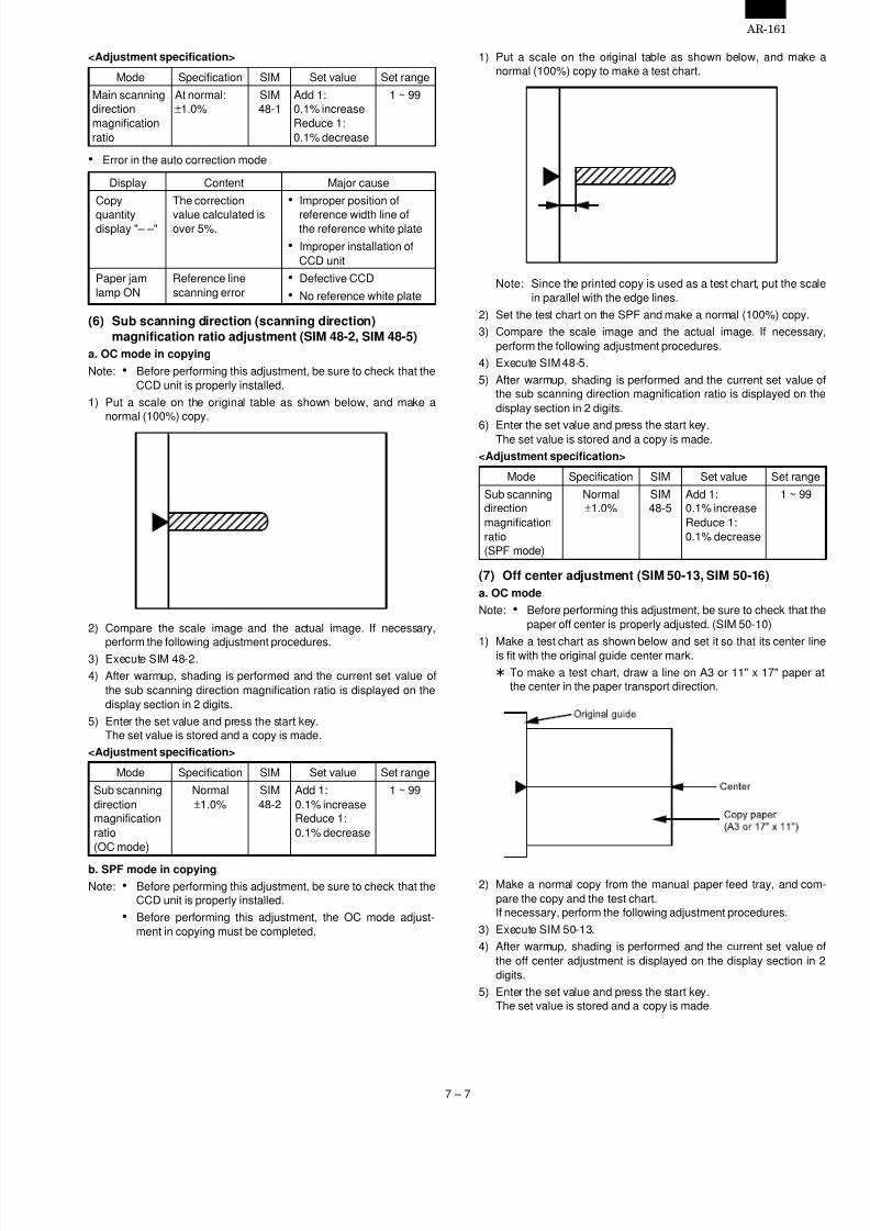
7/27/2019 Sharp Ar 160 & 161ar-161 Service Manual
http://slidepdf.com/reader/full/sharp-ar-160-161ar-161-service-manual 37/67
<Adjustment specification>
Mode Specification SIM Set value Set range
Main scanningdirectionmagnificationratio
At normal:±1.0%
SIM48-1
Add 1:0.1% increaseReduce 1:0.1% decrease
1 ~ 99
• Error in the auto correction mode
Display Content Major cause
Copy
quantitydisplay "– –"
The correction
value calculated isover 5%.
• Improper position of
reference width line ofthe reference white plate
• Improper installation ofCCD unit
Paper jamlamp ON
Reference linescanning error
• Defective CCD
• No reference white plate
(6) Sub scanning direction (scanning direction)
magnification ratio adjustment (SIM 48-2, SIM 48-5)
a. OC mode in copying
Note: • Before performing this adjustment, be sure to check that theCCD unit is properly installed.
1) Put a scale on the original table as shown below, and make anormal (100%) copy.
2) Compare the scale image and the actual image. If necessary,
perform the following adjustment procedures.3) Execute SIM 48-2.
4) After warmup, shading is performed and the current set value ofthe sub scanning direction magnification ratio is displayed on thedisplay section in 2 digits.
5) Enter the set value and press the start key.The set value is stored and a copy is made.
<Adjustment specification>
Mode Specification SIM Set value Set range
Sub scanningdirectionmagnificationratio(OC mode)
Normal±1.0%
SIM48-2
Add 1:0.1% increaseReduce 1:0.1% decrease
1 ~ 99
b. SPF mode in copying
Note: • Before performing this adjustment, be sure to check that theCCD unit is properly installed.
• Before performing this adjustment, the OC mode adjust-ment in copying must be completed.
1) Put a scale on the original table as shown below, and make anormal (100%) copy to make a test chart.
Note: Since the printed copy is used as a test chart, put the scalein parallel with the edge lines.
2) Set the test chart on the SPF and make a normal (100%) copy.
3) Compare the scale image and the actual image. If necessary,perform the following adjustment procedures.
4) Execute SIM 48-5.
5) After warmup, shading is performed and the current set value ofthe sub scanning direction magnification ratio is displayed on thedisplay section in 2 digits.
6) Enter the set value and press the start key.The set value is stored and a copy is made.
<Adjustment specification>
Mode Specification SIM Set value Set range
Sub scanningdirectionmagnificationratio(SPF mode)
Normal±1.0%
SIM48-5
Add 1:0.1% increaseReduce 1:0.1% decrease
1 ~ 99
(7) Off center adjustment (SIM 50-13, SIM 50-16)
a. OC mode
Note: • Before performing this adjustment, be sure to check that thepaper off center is properly adjusted. (SIM 50-10)
1) Make a test chart as shown below and set it so that its center lineis fit with the original guide center mark.
* To make a test chart, draw a line on A3 or 11" x 17" paper atthe center in the paper transport direction.
2) Make a normal copy from the manual paper feed tray, and com-pare the copy and the test chart.If necessary, perform the following adjustment procedures.
3) Execute SIM 50-13.
4) After warmup, shading is performed and the current set value ofthe off center adjustment is displayed on the display section in 2digits.
5) Enter the set value and press the start key.The set value is stored and a copy is made.
AR-161
7 – 7

7/27/2019 Sharp Ar 160 & 161ar-161 Service Manual
http://slidepdf.com/reader/full/sharp-ar-160-161ar-161-service-manual 38/67
<Adjustment specification>
Mode Specification SIM Set value Set range
Originaloff centermode(OC mode)
Single:Center ± 2.0mm
SIM50-18
Add 1:0.1mm shift toR sideReduce 1:0.1mm shift toL side
1 ~ 99
Duplex:Center ±2.5mm
b. SPF mode
Note: • Before performing this adjustment, be sure to check that thepaper off center is properly adjusted.
1) Make a test chart for the center position adjustment and set it onthe SPF.
<Adjustment specification>
Draw a line on a paper in the scanning direction.
2) Make a normal copy from the manual paper feed tray, and com-pare the copy and the original test chart.If necessary, perform the following adjustment procedures.
3) Execute SIM 50-16.
4) After warmup, shading is performed and the current set value ofthe off center adjustment at each paper feed port is displayed onthe display section in 2 digits.
5) Enter the set value and press the start key.
The set value is stored and a copy is made.<Adjustment specification>
Mode Specification SIM Set value Set range
Originaloff centermode(SPFmode)
Single:Center ± 3.0mm
SIM50-16
Add 1:0.1mm shift toR sideReduce 1:0.1mm shift toL side
1 ~ 99
Duplex:Center ±3.5mm
(8) Original sensor adjustment (SIM 43-3)
1) Execute SIM 41-2.
2) Set A3 (11" x 17") paper on the OC table.
3) Press the start key again.
4) The sensor level of the original sensor is automatically checkedand the value with an original - 40 is made as the threshold valuefor scanning. (Automatic setting)
5) Execute SIM 43-3.
6) The light reception level of the original sensor is displayed.
The first digit of the copy quantity display shows "A": Light recep-tion level display
The first digit of the copy quantity display shows "b": Original judgement level display(The mode selection is made with the magnification ratio displaykey.)
7) By changing the paper set on the original table, the original sizeLED sensed by the sensor is lighted.
C. Image density adjustment
(1) Copy mode (SIM 46-1)
1) Set a test chart (UKOG-0162FCZZ) on the OC table as shownbelow.
2) Put several sheets of A3 or 11" x 17" white paper on the testchart.
3) Execute SIM 46-1.
4) After warmup, shading is performed and the current set value ofthe density level is displayed on the display section in 2 digits.
For mode selection, use the density select key.
5) Change the set value with the 10-key to adjust the copy image
density.6) Make a copy and check that the specification below is satisfied.
<Adjustment specification>
Densitymode
Displaylamp
Exposurelevel
Sharp GrayChart output
Set valueSet
rangeAuto Auto — "3" is slightly
copied.The greater theset value is, thegreater thedensity is.The smaller theset value is, thesmaller thedensity is.
1 ~ 99
Manual Manual 3 "3" is slightlycopied.
Photo Photo 3 "3" is slightlycopied.
Tonersave
Manual/ Photo
3 "3" is slightlycopied.
AR-161
7 – 8
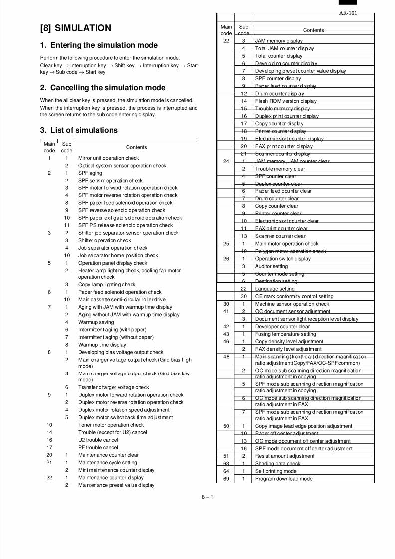
7/27/2019 Sharp Ar 160 & 161ar-161 Service Manual
http://slidepdf.com/reader/full/sharp-ar-160-161ar-161-service-manual 39/67
[8] SIMULATION
1. Entering the simulation mode
Perform the following procedure to enter the simulation mode.
Clear key → Interruption key → Shift key → Interruption key → Startkey → Sub code → Start key
2. Cancelling the simulation mode
When the all clear key is pressed, the simulation mode is cancelled.When the interruption key is pressed, the process is interrupted andthe screen returns to the sub code entering display.
3. List of simulations
Maincode
Subcode
Contents
1 1 Mirror unit operation check2 Optical system sensor operation check
2 1 SPF aging2 SPF sensor operation check3 SPF motor forward rotation operation check
4 SPF motor reverse rotation operation check8 SPF paper feed solenoid operation check9 SPF reverse solenoid operation check10 SPF paper exit gate solenoid operation check11 SPF PS release solenoid operation check
3 2 Shifter job separator sensor operation check3 Shifter operation check4 Job separator operation check10 Job separator home position check
5 1 Operation panel display check2 Heater lamp lighting check, cooling fan motor
operation check3 Copy lamp light ing check
6 1 Paper feed solenoid operation check10 Main cassette semi-circular roller drive7 1 Aging with JAM with warmup time display
2 Aging without JAM with warmup time display4 Warmup saving6 Intermittent aging (with paper)7 Intermittent aging (without paper)8 Warmup time display
8 1 Developing bias voltage output check2 Main charger voltage output check (Grid bias high
mode)3 Main charger voltage output check (Grid bias low
mode)6 Transfer charger voltage check
9 1 Duplex motor forward rotation operation check2 Duplex motor reverse rotation operation check4 Duplex motor rotation speed adjustment5 Duplex motor switchback time adjustment
10 Toner motor operation check14 Trouble (except for U2) cancel16 U2 trouble cancel17 PF trouble cancel20 1 Maintenance counter clear21 1 Maintenance cycle setting
2 Mini maintenance counter display22 1 Maintenance counter display
2 Maintenance preset value display
Maincode
Subcode
Contents
22 3 JAM memory display4 Total JAM counter display5 Total counter display6 Developing counter display7 Developing preset counter value display8 SPF counter display9 Paper feed counter display12 Drum counter display14 Flash ROM version display15 Trouble memory display16 Duplex print counter display17 Copy counter display18 Printer counter display19 Electronic sort counter display20 FAX print counter display21 Scanner counter display
24 1 JAM memory, JAM counter clear2 Trouble memory clear4 SPF counter clear5 Duplex counter clear6 Paper feed counter clear
7 Drum counter clear8 Copy counter clear9 Printer counter clear10 Electronic sort counter clear11 FAX print counter clear13 Scanner counter clear
25 1 Main motor operation check10 Polygon motor operation check
26 1 Operation switch display3 Auditor setting5 Counter mode setting6 Destination setting22 Language setting
30 CE mark conformity control setting30 1 Machine sensor operation check41 2 OC document sensor adjustment
3 Document sensor light reception level display42 1 Developer counter clear43 1 Fusing temperature setting46 1 Copy density level adjustment
2 FAX density level adjustment48 1 Main scanning (front/rear) direction magnification
ratio adjustment(Copy/FAX/OC-SPF common)2 OC mode sub scanning direction magnification
ratio adjustment in copying5 SPF mode sub scanning direction magnification
ratio adjustment in copying6 OC mode sub scanning direction magnification
ratio adjustment in FAX7 SPF mode sub scanning direction magnification
ratio adjustment in FAX50 1 Copy image lead edge position adjustment
10 Paper off center adjustment13 OC mode document off center adjustment16 SPF mode document off center adjustment
51 2 Resist amount adjustment63 1 Shading data check64 1 Self printing mode69 1 Program download mode
AR-161
8 – 1

7/27/2019 Sharp Ar 160 & 161ar-161 Service Manual
http://slidepdf.com/reader/full/sharp-ar-160-161ar-161-service-manual 40/67
4. Contents of simulations
Maincode
Subcode
Contents Details of operationInitialvalue
Set range
1 1 Mirror unit operationcheck
Used to execute scanning at the speed corresponding to the set mag-nification ratio.
100% 50 ~ 200%
Key operation DisplayChanging the magnification ratio:
Fixed magnification ratio keySet magnification ratio:
Fixed magnification ratio LED
2 Optical system sensoroperation check
Used to check MHPS (Mirror home position sensor) ON/OFF state withthe LED on the operation panel.
Display<Lighting when the sensor is ON>MHPS: Paper empty LED
2 1 SPF aging Used to perform SPF document transport.The paper size is not detected. (Excluding postcards, extra large sheet of1m or greater.)With SPF installed: Single transport operationWith RSPF installed: Duplex transport operation
2 SPF sensor operationcheck
Used to check sensors in SPF with the LED on the operation panel.
Display
<Lighting at sensor ON>PW1: JAM LED
PW2: Paper empty LED
PW3: Machine position JAM LED
PW4: SPF JAM LED
PL1: Manual paper feed tray select LED
PL2: Second cassette position JAM LED
P-IN: SPF select LED
P-OUT: Main cassette select LED
3 SPF motor forwardrotation operation check
Used to rotate the SPF motor forward at the speed corresponding to thecurrently set magnification ratio for 10 sec.
100% 50 ~ 200%
Key operation Display
Magnification ratio change:Fixed magnification ratio key
Set magnification ratio:Fixed magnification ratio LED
4 SPF motor reverserotation operation check
Used to rotate the SPF motor reversely for 10 sec.
8 SPF paper feed solenoidoperation check
Used to drive the SPF paper feed solenoid (PSOL) at the cycle of500msec ON and 500msec OFF 20 times.
9 SPF reverse solenoidoperation check
Used to drive the SPF reverse solenoid (RSOL) at the cycle of 500msecON and 500msec OFF 20 times.
10 SPF paper exit gatesolenoid operation check
Used to drive the SPF paper exit gate solenoid (GSOL) at the cycle of500msec ON and 500msec OFF 20 times.
11 SPF PS release solenoidoperation check
Used to drive the SPF PS release solenoid at the cycle of 500msec ONand 500msec OFF 20 times.
3 2 Shifter job separator
sensor operation check
Used to check the sensors state in the shifter job separator with the LED
on the operation panel.Display
<Lighting at sensor ON>
Shifter HP sensor: Machine position JAM LED
Job separator HP sensor: SPF JAM LED
Paper exit full sensor: Second cassette position JAM LED
3 Shifter operation check Used to drive the shifter motor at the speed of printing of A4 (8-1/2 ×11"). Pressing the start key or the clear all key moves the shifter to thehome position.
Key operation
The shifter is moved to the home position: Start key or clear all key
AR-161
8 – 2
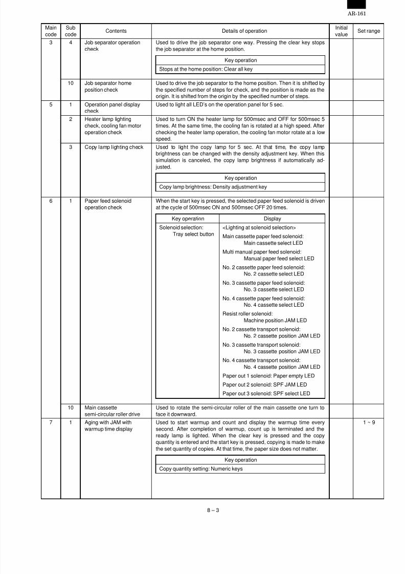
7/27/2019 Sharp Ar 160 & 161ar-161 Service Manual
http://slidepdf.com/reader/full/sharp-ar-160-161ar-161-service-manual 41/67
Maincode
Subcode
Contents Details of operationInitialvalue
Set range
3 4 Job separator operationcheck
Used to drive the job separator one way. Pressing the clear key stopsthe job separator at the home position.
Key operation
Stops at the home position: Clear all key
10 Job separator homeposition check
Used to drive the job separator to the home position. Then it is shifted bythe specified number of steps for check, and the position is made as theorigin. It is shifted from the origin by the specified number of steps.
5 1 Operation panel displaycheck
Used to light all LED’s on the operation panel for 5 sec.
2 Heater lamp lightingcheck, cooling fan motoroperation check
Used to turn ON the heater lamp for 500msec and OFF for 500msec 5times. At the same time, the cooling fan is rotated at a high speed. Afterchecking the heater lamp operation, the cooling fan motor rotate at a lowspeed.
3 Copy lamp lighting check Used to light the copy lamp for 5 sec. At that time, the copy lampbrightness can be changed with the density adjustment key. When thissimulation is canceled, the copy lamp brightness if automatically ad-
justed.
Key operation
Copy lamp brightness: Density adjustment key
6 1 Paper feed solenoidoperation check When the start key is pressed, the selected paper feed solenoid is drivenat the cycle of 500msec ON and 500msec OFF 20 times.
Key operation Display
Solenoid selection:Tray select button
<Lighting at solenoid selection>
Main cassette paper feed solenoid:Main cassette select LED
Multi manual paper feed solenoid:Manual paper feed select LED
No. 2 cassette paper feed solenoid:No. 2 cassette select LED
No. 3 cassette paper feed solenoid:No. 3 cassette select LED
No. 4 cassette paper feed solenoid:No. 4 cassette select LED
Resist roller solenoid:Machine position JAM LED
No. 2 cassette transport solenoid:No. 2 cassette position JAM LED
No. 3 cassette transport solenoid:No. 3 cassette position JAM LED
No. 4 cassette transport solenoid:No. 4 cassette position JAM LED
Paper out 1 solenoid: Paper empty LED
Paper out 2 solenoid: SPF JAM LED
Paper out 3 solenoid: SPF select LED
10 Main cassettesemi-circular roller drive
Used to rotate the semi-circular roller of the main cassette one turn toface it downward.
7 1 Aging with JAM withwarmup time display
Used to start warmup and count and display the warmup time everysecond. After completion of warmup, count up is terminated and theready lamp is lighted. When the clear key is pressed and the copyquantity is entered and the start key is pressed, copying is made to makethe set quantity of copies. At that time, the paper size does not matter.
1 ~ 9
Key operation
Copy quantity setting: Numeric keys
AR-161
8 – 3

7/27/2019 Sharp Ar 160 & 161ar-161 Service Manual
http://slidepdf.com/reader/full/sharp-ar-160-161ar-161-service-manual 42/67
Maincode
Subcode
Contents Details of operationInitialvalue
Set range
7 2 Aging without JAM withwarmup time display
Used to start warmup and count and display the warmup time everysecond. After completion of warmup, count up is terminated and theready lamp is lighted. When the clear key is pressed and the copyquantity is entered and the start key is pressed, copying is made to makethe set quantity of copies. At that time, the paper size does not matter.
1 ~ 99
Key operation
Copy quantity setting: Numeric keys
4 Warmup saving Used to bring the machine to the ready state without warmup.6 Intermittent aging (with
paper)After completion of warmup, counting is stopped and the ready lamp islighted. When the copy quantity is entered and the start key is pressed,copying is made to make the set quantity of copies. After 3 sec standby,copying is made again to make the set quantity of copies. After that thisoperation is repeated. The paper size does not matter.
1 ~ 99
Key operation
Copy quantity setting: Numeric keys
7 Intermittent aging (withoutpaper)
After completion of warmup, counting is stopped and the ready lamp islighted. When the copy quantity is entered and the start key is pressed,copying is made to make the set quantity of copies. After 3 sec standby,copying is made again to make the set quantity of copies. After that thisoperation is repeated. The paper size does not matter.
1 ~ 99
Key operation
Copy quantity setting: Numeric keys
8 Warmup time display Used to count and display the warmup t ime from 0 at every second.
8 1 Developing bias voltageoutput check
Used to output the developing bias for 30 sec. For the adjustment proce-dure of the developing bias, refer to the previous descriptions.
2 Main charger voltageoutput check (Grid biashigh mode)
Used to output the main charger grid bias voltage at the high mode for30 sec. For the adjustment procedure of the main charger grid biasvoltage, refer to the previous descriptions.
3 Main charger voltageoutput check (Grid biaslow mode)
Used to output the main charger grid bias voltage at the low mode for 30sec. For the adjustment procedure of the main charger grid bias voltage,refer to the previous descriptions.
6 Transfer charger vol tage
check
Used to output the transfer charger voltage for 30 sec. For the adjust-
ment procedure of the transfer charger voltage, refer to the previousdescriptions.
9 1 Duplex motor forwardrotation operation check
Used to rotate the duplex motor forward for 30 sec.
2 Duplex motor reverserotation operation check
Used to rotate the duplex motor reversely for 30 sec.
4 Duplex motor rotationspeed adjustment
After completion of warmup, the ready lamp is lighted and the currentlyset duplex motor rotation speed set value is displayed.When the set value is entered and the start key is pressed, the set valueis stored.
Key operation
Duplex motor rotation speed set value: Numeric keys
5 Duplex motor switchbacktime adjustment
After completion of warmup, the ready lamp is lighted and the currentlyset duplex motor switchback time set value is displayed.When the set value is entered and the start key is pressed, the set valueis stored.
Key operation
Duplex motor switchback time set value: Numeric keys
10 Toner motor operationcheck
Used to operate the toner motor for 30 sec.Note: If this simulation is executed with the toner hopper installed, toner
is automatically supplied to the developer. Be careful of overtoner.
14 Trouble (except for U2)cancel
Used to cancel troubles except for U2.
16 U2 trouble cancel Used to cancel U2 trouble.
17 PF trouble cancel Used to cancel PF trouble.
AR-161
8 – 4

7/27/2019 Sharp Ar 160 & 161ar-161 Service Manual
http://slidepdf.com/reader/full/sharp-ar-160-161ar-161-service-manual 43/67
Maincode
Subcode
Contents Details of operationInitialvalue
Set range
20 1 Maintenance counter clear Used to clear the maintenance counter. ∗2
21 1 Maintenance cycle setting Used to display the currently set maintenance cycle at the numbersshown at right. When the set value is entered and the start key ispressed, the set value is stored.
Key operation/Display0: 2500 sheets1: 5000 sheets2: 15000 sheets3: 30000 sheets4: 150000 sheets5: FREE (999999 sheets)
2 Mini maintenance counterdisplay
Used to display the currently set mini maintenance cycle at the numbersshown at right. When the set value is entered and the start key ispressed, the set value is stored.
Key operation/Display0: 2500 sheets1: 5000 sheets2: 10000 sheets3: FREE (999999 sheets)
22 1 Maintenance counterdisplay
Used to display the current maintenance counter value. ∗1
2 Maintenance preset valuedisplay
Used to display the current maintenance preset value (set with SIM21-1). ∗1
3 JAM memory display Used to display a JAM generated during copying on the JAM positiondisplay on the operation panel. Max. 30 recent jams are stored.
Key operation DisplayJAM history select:
Magnification ratio keyThe history number (1 ~ 30) is displayedon the display.The JAM position LED corresponding tothe history number is lighted.
4 Total JAM counter display Used to display the current total JAM counter value. ∗1
5 Total counter display Used to display the current total counter value. ∗1
6 Developing counterdisplay
Used to display the current developing unit counter value. ∗1
7 Developing preset countervalue display
Used to display the current mini maintenance preset value (set with SIM21-2). ∗1
8 SPF counter display Used to display the current SPF counter value. ∗1
9 Paper feed counter display Used to display the current paper feed counter value for each paper feedport. ∗1
Key operationPaper feed port selection: Tray select key
12 Drum counter display Used to display the current drum counter value. ∗1
14 Flash ROM version display Used to display the version number of the flash ROM of each PWB.
15 Trouble memory display Used to display the actually occurred trouble codes on the display on theoperation panel. When the start key is pressed during the main code
display, the sub code is displayed. Max. 20 recent trouble codes arestored.
Key operation DisplaySub code display: Start key Hysteresis 1 → 10: The upper digit of
display "A" ∼ "J" lights up.Hysteresis 11 → 20: The upper digit of
display "A: ∼ "J" blinks.
Trouble code historyselect: Magnification ratiodisplay key
• Display without trouble codeMain code: "----"Sub code: "00"
∗1: Each counter display methodTo display 12345: 123 (0.75 sec) → Blank (0.35sec) → 456 (0.75 sec) → Blank (1.0 sec) → repetition
∗2: Display after clearing each counter000 (0.75 sec) → Blank (0.35sec) → 000 (0.75 sec) → Blank (1.05 sec) → Repetition
AR-161
8 – 5

7/27/2019 Sharp Ar 160 & 161ar-161 Service Manual
http://slidepdf.com/reader/full/sharp-ar-160-161ar-161-service-manual 44/67
Maincode
Subcode
Contents Details of operationInitialvalue
Set range
22 16 Duplex print counterdisplay
Used to display the current duplex print counter value. ∗1
17 Copy counter display Used to display the current copy counter value. ∗1
18 Printer counter display Used to display the current printer counter value. ∗1
19 Electronic sort counterdisplay
Used to display the current electronic sort counter value. ∗1
20 FAX print counter display Used to display the current FAX print counter value. ∗1
21 Scanner counter display Used to display the current scanner counter value.
24 1 JAM memory, JAMcounter clear
Used to clear the JAM memory and the JAM counter. ∗2
2 Trouble memory clear Used to clear the trouble memory. ∗2
4 SPF counter clear Used to clear the SPF counter. ∗2
5 Duplex counter clear Used to clear the duplex counter. ∗2
6 Paper feed counter clear Used to clear the paper feed counter. ∗2
7 Drum counter clear Used to clear the drum counter. ∗2
8 Copy counter clear Used to clear the copy counter. ∗2
9 Printer counter clear Used to clear the printer counter. ∗2
10 Electronic sort counterclear
Used to clear the electronic sort counter. ∗2
11 FAX print counter clear Used to clear the FAX print counter. ∗2
13 Scanner counter clear Used to clear the scanner counter.25 1 Main motor operationcheck
Used to drive the main motor for 30 sec. At that time, the cooling motorrotates at a low speed.When the developing unit is installed, the developing bias, the grid, andthe main charger are driven.When the developing unit is not installed, only the main motor is driven.
10 Polygon motor operationcheck
Used to drive the polygon motor for 30 sec.
26 1 Operation switch display Used to display the installed option on the operation panel. (The LEDcorresponding to the installed option is lighted.)
Key operation DisplayDisplay select:
Magnification ratio key<Lighting with an option installed>When "A" is displayed:
Shifter: Paper empty LEDJob separator: JAM LED
SPF: SPF select LEDRSPF: SPF JAM LED
Dehumidifying heater: Main body JAM LED
Simplex mode: Multi manual paper feed select LED
When "B" is displayed:
Cassette (2nd step): No. 2 cassette select LED
Cassette (3rd step): No. 3 cassette select LED
Cassette (4th step): No. 4 cassette select LED
Memory installed: Paper empty LED
FAX: JAM LED
Printer: Main body JAM LED
ERDH: Main cassette select LED
16CPM: SPF JAM LED
20CPM: SPF select LED
Document sensor: Auto paper select LED
3 Auditor setting Used to display the current auditor setting with the numbers at right.After entering the set value, press the start key, and the set value isstored.
Key operation/Display0: Built-in auditor1: Coin vendor2: Others
∗1: Each counter display methodTo display 12345: 123 (0.75 sec) → Blank (0.35sec) → 456 (0.75 sec) → Blank (1.0 sec) → repetition
∗2: Display after clearing each counter000 (0.75 sec) → Blank (0.35sec) → 000 (0.75 sec) → Blank (1.05 sec) → Repetition
AR-161
8 – 6

7/27/2019 Sharp Ar 160 & 161ar-161 Service Manual
http://slidepdf.com/reader/full/sharp-ar-160-161ar-161-service-manual 45/67
Maincode
Subcode
Contents Details of operationInitialvalue
Set range
26 5 Counter mode setting Used to set the print counter mode in A3 or 11" × 17".Used to display the currently set counter value with the numbers at right.After entering the set value, press the start key, and the set value isstored.
Key operation/Display
0: Total/Developer = 2 counts Maintenance = 2 counts
1: Total/Developer = 1 count Maintenance = 2 counts
2: Total/Developer = 2 counts Maintenance = 1 count3: Total/Developer = 1 count Maintenance = 1 count
6 Destination setting Used to display the current destination sett ing with the numbers at right.After entering the set value, press the start key, and the set value isstored.
Key operation/Display0: Japan1: USA (Inch series)2: Canada (Inch series)3: Germany (AB series)4: UK (AB series)5: Australia (AB series)6: France (AB series)
7: EX inch series8: EX AB series9: EX inch series (FC conformity)
10: EX AB series (FC conformity)11: Taiwan, China (AB series)
22 Language setting Used to display the current setting of the language information with thenumber at right. After entering the set value, press the start key, and theset value is stored.
Key operation/Display0: Japanese1: English2: French
3: German4: Italian5: Dutch6: Swedish7: Spanish
30 CE mark conformitycontrol setting
Used to display the current setting of CE mark conformity control with thenumber at right. After entering the set value, press the start key, and theset value is stored.
Key operation/Display0: CE mark control OFF1: CE mark control ON
30 1 Machine sensor operation
check
Used to check the sensors in the machine transport system with LED on
the operation panel.Display
<Lighting at sensor ON>Paper entry sensor: Machine position JAM LEDDuplex sensor: SPF JAM LEDPaper exit sensor: JAM LEDNo. 2 cassette transport sensor: No. 2 cassette position JAM LEDNo. 3 cassette transport sensor: No. 3 cassette position JAM LEDNo. 4 cassette transport sensor: No. 4 cassette position JAM LED
41 2 OC document sensoradjustment
Used to read the document sensor input value with paper and performthe sensor detection level adjustment. For the adjustment procedure ofthe document sensor input value, refer to the previous descriptions.
AR-161
8 – 7

7/27/2019 Sharp Ar 160 & 161ar-161 Service Manual
http://slidepdf.com/reader/full/sharp-ar-160-161ar-161-service-manual 46/67
Maincode
Subcode
Contents Details of operationInitialvalue
Set range
41 3 Document sensor lightreception level display
Used to display the light reception level and the detection level of thedocument sensor. (The sensor level adjusted with SIM 41-2 is dis-played.)
Key operation Display
Light reception/Detectionlevel select: Magnificationratio display key
Display at the 3rd digit
"A": Light reception level display
"b": Document detection level
lighting LEDSensor select: Magnificationratio select key Sensor A: A3 document size LED
Sensor B: A4 document size LED
Sensor C: A4R document size LED
Sensor D: B4 document size LED
42 1 Developer counter clear Used to clear the developer counter. ∗2
43 1 Fusing temperature setting Used to display the current setting of the fusing temperature with thenumber at right. After selecting the fusing temperature with the mag-nification ratio display key, press the start key, and the set value isstored.
Key operation
Fusing temperature select: Magnification ratio display key
46 1 Copy density leveladjustment
After completion of warmup, shading is performed and the currently setcopy density level is displayed. For the adjustment procedure, refer tothe previous descriptions.
1 ~ 99
Key operation Display
Mode select: Mode select key <LED lighting at each mode selection>
Auto mode: AE LED
Manual mode: TEXT LED
Photo mode: PHOTO LED
Toner save mode: TEXT/PHOTO LED
2 FAX density leveladjustment
After completion of warmup, shading is performed and the currently setFAX density level is displayed. For the adjustment procedure, refer to the
previous descriptions.
1 ~ 99
Key operation Display
Mode select:Mode select key
<LED lighting at each mode selection>
Standard mode: Standard LED
Small character mode:Small character LED
Fine mode: Fine LED
Ultra fine mode: Ultra fine LED
Photo mode: Photo LED
48 1 Main scanning (front/rear)direction magnificationratio adjustment
(Copy/FAX/OC-SPFcommon)
After completion of warmup, shading is performed and the currently setmain scanning (front/rear) direction magnification ratio adjustment is per-formed. For the adjustment procedure, refer to the previous descriptions.
1 ~ 99
Key operation Display
Adjustment mode select:Magnification ratio key
Auto magnification ratio adjustment:AE LED
Manual main scanningdirection magnificationratio adjustment
Manual magnification ratio adjustment:TEXT LED
Set value: Numeric keys
∗1: Each counter display methodTo display 12345: 123 (0.75 sec) → Blank (0.35sec) → 456 (0.75 sec) → Blank (1.0 sec) → repetition
∗2: Display after clearing each counter000 (0.75 sec) → Blank (0.35sec) → 000 (0.75 sec) → Blank (1.05 sec) → Repetition
AR-161
8 – 8
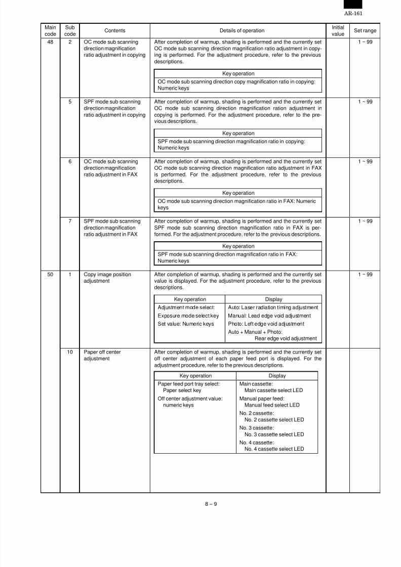
7/27/2019 Sharp Ar 160 & 161ar-161 Service Manual
http://slidepdf.com/reader/full/sharp-ar-160-161ar-161-service-manual 47/67
Maincode
Subcode
Contents Details of operationInitialvalue
Set range
48 2 OC mode sub scanningdirection magnificationratio adjustment in copying
After completion of warmup, shading is performed and the currently setOC mode sub scanning direction magnification ratio adjustment in copy-ing is performed. For the adjustment procedure, refer to the previousdescriptions.
1 ~ 99
Key operation
OC mode sub scanning direction copy magnification ratio in copying:Numeric keys
5 SPF mode sub scanningdirection magnificationratio adjustment in copying
After completion of warmup, shading is performed and the currently setOC mode sub scanning direction magnification ration adjustment incopying is performed. For the adjustment procedure, refer to the pre-vious descriptions.
1 ~ 99
Key operation
SPF mode sub scanning direction magnification ratio in copying:Numeric keys
6 OC mode sub scanningdirection magnificationratio adjustment in FAX
After completion of warmup, shading is performed and the currently setOC mode sub scanning direction magnification ratio adjustment in FAXis performed. For the adjustment procedure, refer to the previousdescriptions.
1 ~ 99
Key operation
OC mode sub scanning direction magnification ratio in FAX: Numerickeys
7 SPF mode sub scanningdirection magnificationratio adjustment in FAX
After completion of warmup, shading is performed and the currently setSPF mode sub scanning direction magnification ratio in FAX is per-formed. For the adjustment procedure, refer to the previous descriptions.
1 ~ 99
Key operation
SPF mode sub scanning direction magnification ratio in FAX:Numeric keys
50 1 Copy image positionadjustment
After completion of warmup, shading is performed and the currently setvalue is displayed. For the adjustment procedure, refer to the previousdescriptions.
1 ~ 99
Key operation DisplayAdjustment mode select: Auto: Laser radiation timing adjustment
Exposure mode select key Manual: Lead edge void adjustment
Set value: Numeric keys Photo: Left edge void adjustment
Auto + Manual + Photo:Rear edge void adjustment
10 Paper off centeradjustment
After completion of warmup, shading is performed and the currently setoff center adjustment of each paper feed port is displayed. For theadjustment procedure, refer to the previous descriptions.
Key operation Display
Paper feed port tray select:Paper select key
Main cassette:Main cassette select LED
Off center adjustment value:numeric keys
Manual paper feed:Manual feed select LED
No. 2 cassette:No. 2 cassette select LED
No. 3 cassette:No. 3 cassette select LED
No. 4 cassette:No. 4 cassette select LED
AR-161
8 – 9
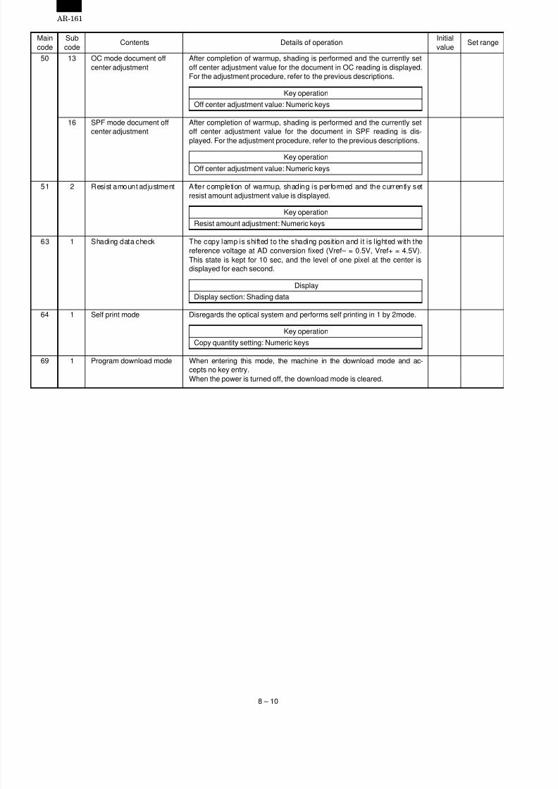
7/27/2019 Sharp Ar 160 & 161ar-161 Service Manual
http://slidepdf.com/reader/full/sharp-ar-160-161ar-161-service-manual 48/67
Maincode
Subcode
Contents Details of operationInitialvalue
Set range
50 13 OC mode document offcenter adjustment
After completion of warmup, shading is performed and the currently setoff center adjustment value for the document in OC reading is displayed.For the adjustment procedure, refer to the previous descriptions.
Key operation
Off center adjustment value: Numeric keys
16 SPF mode document offcenter adjustment
After completion of warmup, shading is performed and the currently setoff center adjustment value for the document in SPF reading is dis-
played. For the adjustment procedure, refer to the previous descriptions.
Key operation
Off center adjustment value: Numeric keys
51 2 Resist amount adjustment After completion of warmup, shading is performed and the currently setresist amount adjustment value is displayed.
Key operation
Resist amount adjustment: Numeric keys
63 1 Shading data check The copy lamp is shifted to the shading position and it is lighted with thereference voltage at AD conversion fixed (Vref– = 0.5V, Vref+ = 4.5V).This state is kept for 10 sec, and the level of one pixel at the center isdisplayed for each second.
Display
Display section: Shading data
64 1 Self print mode Disregards the optical system and performs self printing in 1 by 2mode.
Key operation
Copy quantity setting: Numeric keys
69 1 Program download mode When entering this mode, the machine in the download mode and ac-cepts no key entry.When the power is turned off, the download mode is cleared.
AR-161
8 – 10

7/27/2019 Sharp Ar 160 & 161ar-161 Service Manual
http://slidepdf.com/reader/full/sharp-ar-160-161ar-161-service-manual 49/67
[9] USER PROGRAM
The factory setting can be changed according to the operating conditions.
1. User program functions
Function Outline Default
Auto clear When a certain time is passed after completion of the machine operation, the mode isreturned to the initial state automatically.The time to return to the initial state can be set in the range of 30 ~ 120 sec by the unit of 30
sec. This function can be canceled.
60 sec
Pre-heat When the machine is left unused with the power ON, the power consumption level isautomatically lowered to about 60Wh (*1). The time to operate this function can be set inthe range of 30 sec ~ 120 sec by the unit of 30 sec. This function can be canceled.When this function operates, the pre-heat lamp on the operation panel lights up.To cancel the pre-heat state, press any key on the operation panel.(When the START key is pressed, pre-heat is canceled and copying is started,)This function is canceled with the document is set or the tray is pulled out.
90 sec
Auto power shut off passing time When the machine is left unused with the power ON, the power consumption isautomatically lowered to about 4.8Wh (*1). The time to operate this function can be set inthe range of 30 min to 240 min. When this function operates, all the lamps except for thepre-heat lamp turn off.To cancel the auto power shut off state, press the START key.
30 min
Stream feeding mode (with
SPF/R-SPF installed)
After making copy with SPF/R-SPF, the document feed display lamp blinks, set the
document, and the document is automatically fed.
Cancel
Auto power shut off setting The auto power shut off function can be canceled. Setting
2 in 1/4 in 1 solid line frame setting(with electronic sort board,SPF/R-SPF installed)
Images on two or more pages are copied on one sheet of paper (2 in 1/4 in 1). When thisfunction is used, copying can be made with the solid lines at the boundaries of images.
Setting
Rotation copy(With electronic sort board installed)
When the paper auto selection function is operating, if there is no paper of the suitable sizeor the suitable direction, paper of the same size but of different direction is automaticallyselected and the document images are rotated by 90 degrees to copy.The magnification ratio auto select function operates and rotates document images by 90degrees to make proper copy when the document images and the paper direction differ fromeach other.
Cancel
Paper auto selection The paper of the same size as the document size selected by the document size set key(A3, B4, A4, A4R, B5, B5R 11" × 17", 8.5" × 14", 8.5" × 13", 8.5" × 11", 8.5" × 11"R, 8.5" ×5.5" only) is automatically selected. This function is canceled.
Setting
Tray auto selection (with 1-steppaper feed unit, 2-step paper feedunit installed)
The paper of the same size as the document size selected by the document size set key(A3, B4, A4, A4R, B5, B5R 11" × 17", 8.5" × 14", 8.5" × 13", 8.5" × 11", 8.5" × 11"R, 8.5" ×5.5" only) is automatically selected. This function is canceled.
Setting
Department counter Refer to "3. Department counter setting."
Edge erase (with electronic sortboard installed)
Shades around images and shades at the binding margin can be erased by this function.The erase range can be set in the range of 0 ~ 20mm by the unit of 5mm.
10mm
2 in 1 layout (with electronic sortboard, SPF/R-SPF installed)
The layout pattern for copying images of two pages on one page can be selected. Pattern A
4 in 1 layout (with electronic sortboard, SPF/R-SPF installed)
The layout pattern for copying images of four pages on one page can be selected. Pattern A
*1: The power consumption in pre-heat, auto power shut off depends on the operating conditions.
Pattern A Pattern B
Pattern A Pattern B Pattern C Pattern D
AR-161
9 – 1

7/27/2019 Sharp Ar 160 & 161ar-161 Service Manual
http://slidepdf.com/reader/full/sharp-ar-160-161ar-161-service-manual 50/67
2. Setting change procedure
Example: Changing the time for operating the auto clear function(from 60 sec to 120 sec)
1) Press and hold the density adjustment key for 5 sec to startsetting.
• When lamps start blinking at the same time,the copy quantity display shows "--" the digit of 10 blinking.
2) Select the function code with the numeric key.
• The code of the selected function is displayed (blinking) on thedigits of 10 and 100.
• For auto clear, select 1.
• Select the suitable code according to the table below.
User program setting contents
Function Function code Setting code
Auto clear 1 0 (Cancel)
1 (30 sec)
∗2 (60 sec)
3 (90 sec)
4 (120 sec)
Pre-heat 2 0 (Cancel)
1 (30 sec)
2 (60 sec)∗3 (90 sec)
4 (120 sec)
Auto power shut off passingtime (*2)
3 ∗1 (30 sec)
2 (60 sec)
3 (90 sec)
4 (120 sec)
5 (240 sec)
Stream feeding mode 4 ∗0 (Cancel)
1 (Setting)
Auto power shut off functionsetting (*2)
5 0 (Cancel)
∗1 (Setting)
2 in 1/4 in 1 solid frame setting 6∗0 (Cancel)1 (Setting)
Rotation copy 7 0 (Cancel)
∗1 (Setting)
Paper auto selection 8 0 (Cancel)
∗1 (Setting)
Tray auto selection 9 0 (Cancel)
∗1 (Setting)
Department counter (*1) 10 ~ 15
Edge erase 16 0 (0mm)
1 (5mm)
∗2 (10mm)
3 (15mm)
4 (20mm)
2 in 1 layout (*3) 17 ∗1 (Pattern A)
2 (Pattern B)
4 in 1 layout (*3) 18 ∗1 (Pattern A)
2 (Pattern B)
3 (Pattern B)
4 (Pattern B)
∗ Setting at the factory shipping
*1. For the setting procedure, refer to "3. Department counter."
*2. With the auto power shut off canceled (function code "5", setcode "0", auto power shut off time setting code "3"), the modeenters the auto power shut off setting mode automatically.
*3. For the layout pattern, refer to page 9-1.
• The number of the selected function blinks on the digit of 1 orthe copy quantity display.
Cancel: When any key is pressed by mistake, press the clear keyand press the proper key.
3) Press the START key.
• The selected function code is changed from blinking to lighting.
• The currently set code blinks on the digit of 1.
4) Select the setting code with the numeric key.
• For setting to 80 sec, select 3.
• Make setting referring to the setting codes of "User programsetting contents."
Cancel: When any wrong key is pressed, press the clear key andresume from procedure 2.
5) Press the START key,
• The selected setting code is changed from blinking to lighting.The setting is completed with the above operation.
Memo: To set another function, press the clear key after this proce-dure and resume from procedure 2.
6) Press the density adjustment key to end the setting.
• lamps go off. The copy quantity displayreturns to the normal display.
3. Department counter settingNote: The department counter is effective only in copying. Counting
is not made in FAX and printer output.
When the department counter is set, the copy count for each depart-ment (max. 20 dept.) can be made and displayed when necessary.
With the department counter set, copying cannot be made unless theregistered number (password number of 3 digits) is entered.
1) Press and hold the density adjustment key for about 5 sec tostart setting.
• lamps start blinking at the same time, andthe copy quantity display displays "--" and the digit of 10 blinks.
2) Select the function code with the numeric key.
• Refer to the function code for setting.
Setting contents of department counters
Function Function code
Setting content 10 Department countersetting or cancel. Factorysetting: Cancel
Departmentcountersetting/cancel
11 Department numberrecording.Max. 20 department canbe recorded.
Departmentnumber recording
12 Recorded departmentnumber is changed.
Departmentnumber delete
13 Recorded number isdeleted.
Copy quantitydisplay (Total)
14 The copy quantity in eachdepartment is displayed.The count is made up to49,999 sheets. From that,counting is started from 0.
Copy quantitydelete (Totaldelete)
15 The counted copy quantityis canceled. The count ofeach department or that ofall the departments can bedeleted.
• The entered number blinks on the digits of 100 and 10 on thecopy quantity display.
Cancel: When a wrong key is pressed, press the clear key and enterthe correct key.
AR-161
9 – 2

7/27/2019 Sharp Ar 160 & 161ar-161 Service Manual
http://slidepdf.com/reader/full/sharp-ar-160-161ar-161-service-manual 51/67
3) Press the START key.
• The selected function code is changed from blinking to lighting.
• The currently set code blinks on the digit of 1.
Cancel: When the "E" (error code) is lighted on the digit of 1, pressthe clear key and return to procedure 2.
4) Perform setting of the department counter.Perform setting referring to "F.Copy quantity delete" in "A.Department counter setting/cancel."
5) Press the density adjustment key to end the setting proce-dure.
• lamps go off.• The copy quantity display returns to the normal display.
A. Department counter setting/cancel (Functioncode: 0)
Used to set or cancel the department counter. When this setting ismade, the copy quantity display lights up with "--."
Under this state, the department number in 3 digits must be enteredto operate the machine.
After entering the function code "0," use the numeric key to set orcancel the department counter.
1) To set the department counter, select "1." To cancel, select "0."Then press the START key.
Memo: After this setting, use the "Department number recording" to
record the department number of each department.(Max. 20 departments can be recorded.)
2) Press the clear key.
B. Department number recording (Function code:11)
Used to record the department number.
When the function code "1" is entered, the copy quantity displayblinks with "--."
When the recorded department number reaches 20, the error code of
"11E" is displayed.
1) Use the numeric key to enter the number of 3 digits (except for000) and press the START key.
• When the recorded number or "000" is entered, the entered
number blinks. In this case, enter another number.• To register another department number, repeat the same pro-
cedure 1) above.
2) After completion of recording, press the clear key.
• The registered department number and each department namemust be recorded. (Since the department name cannot beregistered, they must be recorded for total calculation.)
C. Department number change (Function code: 12)Used to change the department number.
Enter the function code "12" and select the department number to beregistered.
If there is no registered department number, the error code of "12E"is displayed.
1) Select the department number with % key, and press the STARTkey.
• The copy quantity display shows "- - - - ."
2) Use the numeric key to enter a new department number (3 digitsexcept for 000), and press the START key.
• When the recorded number or "000" is entered, the enterednumber blinks. In this case, enter another number.
• To register another department number, repeat the same pro-cedures 1) and 2) above.
3) After completion of changing, press the clear key.
D. Department number delete (Function code 13)Delete the department number.
Enter the department code (13) and select all departments clear orspecified department clear.
When there is no registered department number, the error code "13E"is displayed.
(1) All departments clear
1) Press "1" key.
2) Press the START key.
(2) Specified department clear1) Press "0" key.
2) Select the department number to be deleted with % key.
3) Press the START key.
E. Copy quantity display (sum total) (Functioncode: 14)
The copy quantity of each department is displayed.
Enter the function code "14" and select the department number ofwhich the total copy quantity is to be displayed.
If there is no registered department number, the error code "14E" isdisplayed.
1) Select the department number with % key.
2) Press and hold "0" key, and the copy quantity will be displayed.
• The copy quantity is displayed in two steps.(Example) Copy quantity: 12, 345
• To display the copy quantity of another department, repeat thesame procedure 1) and 2).
3) Press the clear key to terminate the procedure.
F. Copy quantity clear (total clear) (Function code:15)
The copy quantity of each department is cleared.
After entering the function code "15", select all department clear orspecified department clear.
If there is no registered department, the error code "15E" is dis-played.
(1) All department total clear
1) Press "1" key.
2) Press the START key.
(2) Specified department clear
1) Press "0" key.
2) Select the department number with % key.
3) Press the START key.
AR-161
9 – 3

7/27/2019 Sharp Ar 160 & 161ar-161 Service Manual
http://slidepdf.com/reader/full/sharp-ar-160-161ar-161-service-manual 52/67
[10] TROUBLE CODE LIST
Classification Function Main code Sub code Trouble name Remark
Electricalsystem error
Copier H2 00 Thermistor open error Thermistor is open
H3 00Fusing temperature abnormality(Abnormally high temperature detection)
Abnormally high fusing temperature
H4 00Fusing temperature abnormality(Abnormally low temperature detection)
Abnormally low fusing temperature
CC Media sensor error Document detection error
U2 04 EEPROM communication error EEPROM abnormality
11Counter SAM error EEPROM counter area SAM
abnormality
12Adjustment value SAM error EEPROM adjustment value memory
area SAM abnormality
F5 02 Copy lamp error Copy lamp disconnection
FAX F6 00 FAX board communication trouble
10 FAX board trouble
80FAX board communication trouble(Protocol)
81FAX board communication trouble(Parity)
82FAX board communication trouble(Overrun)
84FAX board communication trouble(Framing)
88FAX board communication trouble(Timeout)
Printer F9 00 Printer board communication trouble
10 Printer board trouble
80Printer board communication trouble(Protocol)
81Printer board communication trouble(Parity)
82Printer board communication trouble(Overrun)
84Printer board communication trouble
(Framing)
88Printer board communication trouble(Timeout)
Electronic sort E100
Electronic sort board communicationtrouble
10 Electronic sort board trouble
11 ASIC error ASIC abnormality
12 Image compression error JBIG IC abnormality
13 Flash ROM error Program ROM abnormality
14 RAM error Work RAM abnormality
15 Page memory error Print buffer abnormality
16SIMM error Compression storing memory
abnormality
17 Image rotating RAM error Rotating RAM abnormality
80Electronic sort board communicationtrouble (Protocol)
81Electronic sort board communicationtrouble (Parity)
82Electronic sort board communicationtrouble (Overrun)
84Electronic sort board communicationtrouble (Framing)
88Electronic sort board communicationtrouble (Timeout)
AR-161
10 – 1
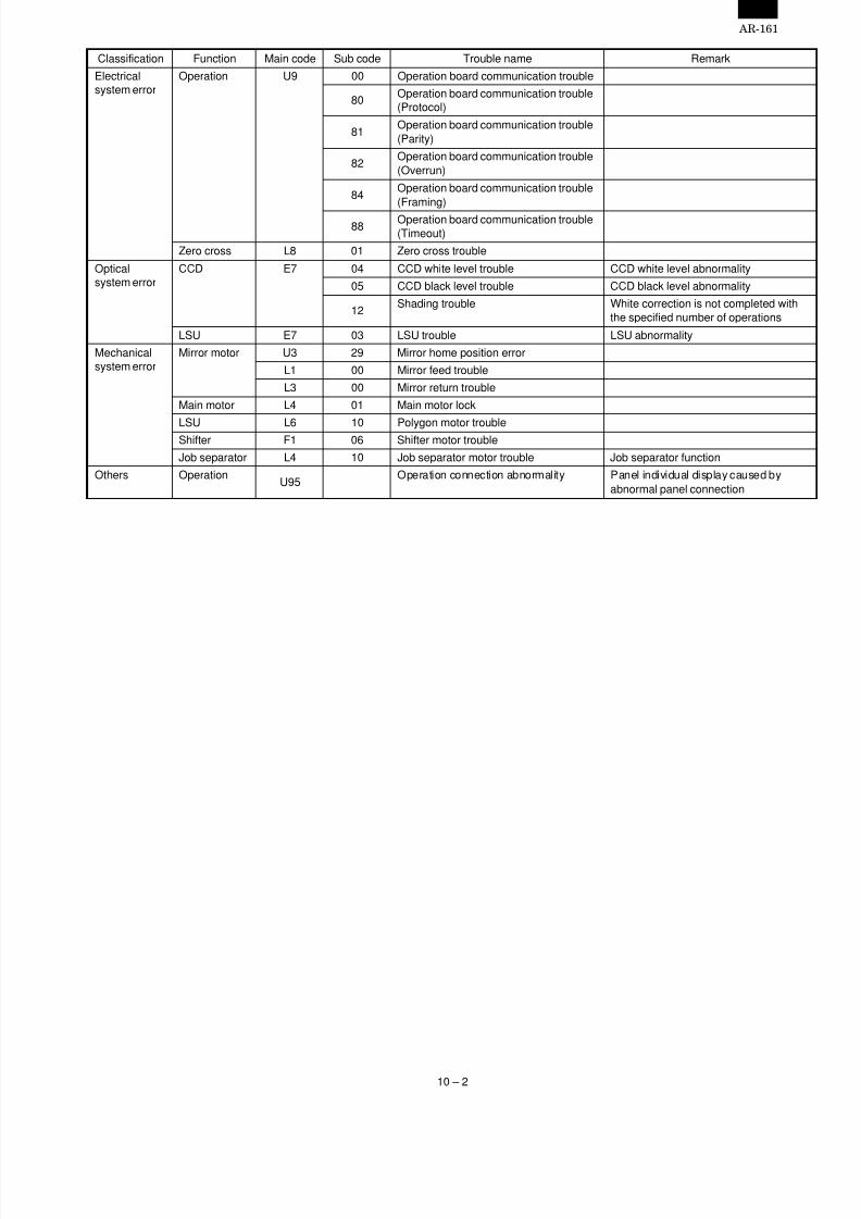
7/27/2019 Sharp Ar 160 & 161ar-161 Service Manual
http://slidepdf.com/reader/full/sharp-ar-160-161ar-161-service-manual 53/67
Classification Function Main code Sub code Trouble name Remark
Electricalsystem error
Operation U9 00 Operation board communication trouble
80Operation board communication trouble(Protocol)
81Operation board communication trouble(Parity)
82Operation board communication trouble(Overrun)
84Operation board communication trouble(Framing)
88 Operation board communication trouble(Timeout)
Zero cross L8 01 Zero cross trouble
Opticalsystem error
CCD E7 04 CCD white level trouble CCD white level abnormality
05 CCD black level trouble CCD black level abnormality
12Shading trouble White correction is not completed with
the specified number of operations
LSU E7 03 LSU trouble LSU abnormality
Mechanicalsystem error
Mirror motor U3 29 Mirror home position error
L1 00 Mirror feed trouble
L3 00 Mirror return trouble
Main motor L4 01 Main motor lock
LSU L6 10 Polygon motor troubleShifter F1 06 Shifter motor trouble
Job separator L4 10 Job separator motor trouble Job separator function
Others OperationU95
Operation connection abnormality Panel individual display caused byabnormal panel connection
AR-161
10 – 2

7/27/2019 Sharp Ar 160 & 161ar-161 Service Manual
http://slidepdf.com/reader/full/sharp-ar-160-161ar-161-service-manual 54/67
[11] MAINTENANCE
1. Maintenance table
!: Check (Clean, adjust, or replace when required.) F: Clean b: Replace v: Adjust 6: Lubricate
Unit name Part nameWhen calling orreplacing the kit
150k
Transfer section Charger unit F F
Transfer paper guide F F
Optical section Lamp unit Reflector F F
Mirror F F
No. 2/3 mirror unit Mirror F F
Pulley ! !
CCD peripheral Lens F F
Glass Table glass F F
White plate F F
Other Drive wire ! !
Rail !6 !6
Document cover F F
Document size sensor F F
LSU Dust-proof glass F F
Paper feed section Multi paper feed section Takeup roller F F
Paper feed roller F F
Spring clutch F6 F6
Cassette section Paper feed roller F F
Spring clutch F6 F6
Paper transport section PS roller F F
Transport (paper exit) rollers F F
Spring clutch F6 F6
Fusing section Upper heat roller F b
Pressure roller F F
Pressure roller bearing ! F6
Upper separation pawl ! F
Lower separation pawl! F
Drive section Gears !6 !6
Belts ! F
AR-161
11 – 1

7/27/2019 Sharp Ar 160 & 161ar-161 Service Manual
http://slidepdf.com/reader/full/sharp-ar-160-161ar-161-service-manual 55/67
[12] DISASSEMBLY ANDASSEMBLY
WARNING: Before performing the disassembly procedure, be sureto remove the power cord to prevent against an electricshock.
No. Item Page1 High voltage section 12-12 Optical section 12-1
3 Fusing section 12-24 Paper exit section 12-45 MCU 12-66 Optical frame unit 12-67 LSU 12-68 Tray paper feed section/Paper transport section 12-79 Manual multi paper feed section 12-810 Power section 12-1011 Developing section 12-1112 Process section 12-12
1. High voltage section
No. ContentA Transfer charger unitB Charger wire
A. Transfer charger unit
B. Charger wireInstallation: The spring tip must be between two reference ribs.
• The charger wire must be free from twist or bending.
• Be sure to put the charger wire in the V groove.
2. Optical section
No. Content
A Table glassB Copy lamp unit
C Copy lamp
D Lens unit
A. Table glass
(2)
(1 )
(4)
(3)
(3)
(5)
(5)
(2)
(1 )(1 )
(1 )
(1 )
(1 )
(1 )
(3)
(1 )
(1 )(2)
(3)
(3)
(4)
AR-161
12 – 1

7/27/2019 Sharp Ar 160 & 161ar-161 Service Manual
http://slidepdf.com/reader/full/sharp-ar-160-161ar-161-service-manual 56/67
B. Copy lamp unitDisassembly: Be sure to put No. 2/3 mirror unit to the positioning
plate (A).
Assembly: Put the notched surface of wire holder (3) downward,tighten temporarily, and install.
Adjustment: Main scanning direction distortion balance adjustment
C. Copy lamp
D. Lens unit
3. Fusing section
No. Contents
A Fusing unit
B Thermostat
C Thermistor
D Heater lamp
E Upper heat roller
F Separation pawl
G Lower heat roller
A. Fusing unit removal
(2)
(3)
(2)
(3)
(1 )
(A)
(A)
(4)(4)
(5)
(6)
(4)
(5)
(3)
(1 )
(1 )
(2) (2)
(3)
(1 )(1 )
AR-161
12 – 2

7/27/2019 Sharp Ar 160 & 161ar-161 Service Manual
http://slidepdf.com/reader/full/sharp-ar-160-161ar-161-service-manual 57/67
B. Thermostat
C. Thermistor
Installation: Check that the thermistor is in contact with the upperheat roller.
D. Heater lampAssembly: Insert the spring (A) into the hole (B) in the fusing frame.
Assembly: Put the paper guide earth spring (A) under the paperguide (B) before fusing.
Disassembly: There are three pawls on the fusing cover. Removethe screws and slide the fusing cover to the right toremove.The heater lamp is fixed on the fusing cover with ascrew. Slide the fusing cover to the front and removethe screw, then remove the heater lamp.
Assembly: Put the fusing harness (A) on the heater lamp (B) asshown in the figure and fix them together.Place the fusing harness inside the rib (C).
(2)
(3)
(1 )
(1 )
(2)
(1 )
(A)(B)
(2)
(1) (2)
(3)
(4)
(3)
(B)(A)
(6)
(5)
(8)
(9)
(7)
(8)
(10)
(A)
(B)
(C)
AR-161
12 – 3
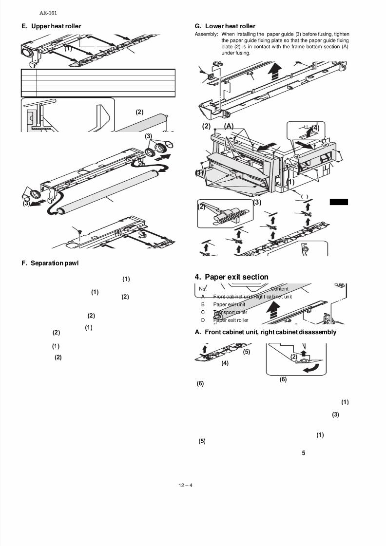
7/27/2019 Sharp Ar 160 & 161ar-161 Service Manual
http://slidepdf.com/reader/full/sharp-ar-160-161ar-161-service-manual 58/67
E. Upper heat roller
F. Separation pawl
G. Lower heat rollerAssembly: When installing the paper guide (3) before fusing, tighten
the paper guide fixing plate so that the paper guide fixingplate (2) is in contact with the frame bottom section (A)under fusing.
4. Paper exit section
No. ContentA Front cabinet unit/Right cabinet unit
B Paper exit unit
C Transport roller
D Paper exit roller
A. Front cabinet unit, right cabinet disassembly
(2)
(1 )
(4)
(3)
(3)
(2)
(1 )
(2)
(1 )
(2)(1 )
(1 )
(2)
(1 )
(4)
(1 )
(2)(3)
(2) (A)
(3)
(2)
(1 )
(1 )
(6)(6)
(5)
(4)
5
(5)
AR-161
12 – 4

7/27/2019 Sharp Ar 160 & 161ar-161 Service Manual
http://slidepdf.com/reader/full/sharp-ar-160-161ar-161-service-manual 59/67
B. Paper exit unit
C. Transport roller
D. Paper exit roller
Assembly: Insert the spring pin so that the waveform (A) of thespring pin faces in the longitudinal direction of the paperexit drive gear long hole (B).Be sure to insert two ribs (C) into the groove (D).
(1 )
(2)
(5)
(B)
(A)
3
(4)
(4)
(7)
(6)
(8)
(6)
(8)
(10)
(9)
(9)
(1 )
(2)
(1 )
(3)
(4)
(6)
(7)
(5)
(5)
(1 )
(3)
(2)
(2)
AR-161
12 – 5

7/27/2019 Sharp Ar 160 & 161ar-161 Service Manual
http://slidepdf.com/reader/full/sharp-ar-160-161ar-161-service-manual 60/67
5. MCUNo. Content
A MCU
A. MCU disassemblyNote: When replacing the MCU PWB, be sure to replace the
EEPROM of the MCU PWB to be replaced.
6. Optical frame unit
No. Content
A Optical frame unit
A. Optical frame unit
Installation: Install the optical unit in the sequence shown above.
7. LSUNo. Content
A LSU unit
A. LSU unit
(4)
(4)
(5)
(B)(A)
(D)
(C)
(C)
(8)
(6)
(6)
(7)
(7)
(1)
(1)(2)
(1)
(1)(1)
(1)
(2)
(1)
(2)
(3)
(1)
(2)
(1)
(1)
(3)
(4)
AR-161
12 – 6
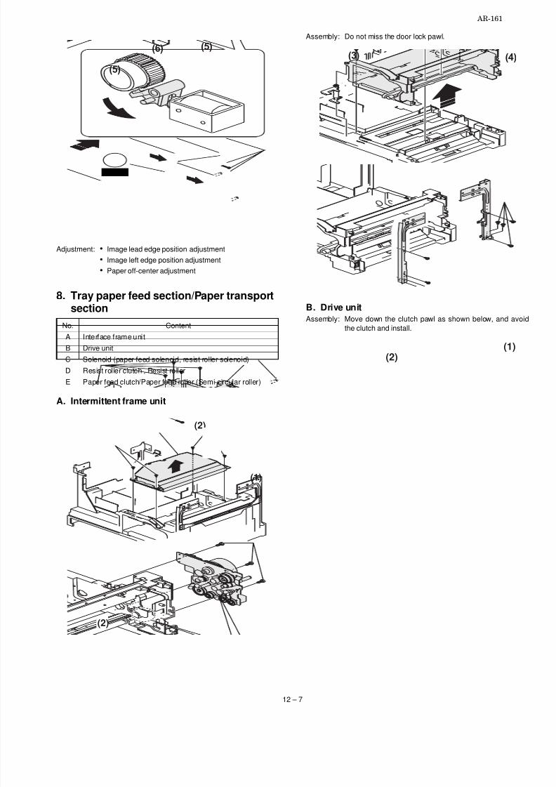
7/27/2019 Sharp Ar 160 & 161ar-161 Service Manual
http://slidepdf.com/reader/full/sharp-ar-160-161ar-161-service-manual 61/67
Adjustment: • Image lead edge position adjustment
• Image left edge position adjustment
• Paper off-center adjustment
8. Tray paper feed section/Paper transportsection
No. Content
A Interface frame unit
B Drive unit
C Solenoid (paper feed solenoid, resist roller solenoid)
D Resist roller clutch , Resist roller
E Paper feed clutch/Paper feed roller (Semi-circular roller)
A. Intermittent frame unit
Assembly: Do not miss the door lock pawl.
B. Drive unitAssembly: Move down the clutch pawl as shown below, and avoid
the clutch and install.
(6) (5)
(5)
(1)
(1)
(2)
(2)
(4)(3)
(1)(2)
AR-161
12 – 7

7/27/2019 Sharp Ar 160 & 161ar-161 Service Manual
http://slidepdf.com/reader/full/sharp-ar-160-161ar-161-service-manual 62/67
C. Solenoid (paper feed solenoid, resist rollersolenoid)
D. Resist roller clutch/Resist roller
E. Paper feed clutch/Paper feed roller(Semi-circular roller)
9. Manual multi paper feed section
No. ContentA Manual multi paper feed sectionB Manual transport clutchC Manual paper feed clutchD Manual transport roller/Manual paper feed rollerE Multi feed solenoid
A. Manual multi paper feed
(1)(2)
(2)
(3)
(1 )
(4)
(3)
(2)
(3)
(3)
(4)
(1 )
(3)
(2)
(2)
(1 )
(2)
(3)
(A)
AR-161
12 – 8

7/27/2019 Sharp Ar 160 & 161ar-161 Service Manual
http://slidepdf.com/reader/full/sharp-ar-160-161ar-161-service-manual 63/67
B. Manual transport clutch
C. Manual paper feed clutch
Disassembly: Set up the shutter arm (1) then remove it.
Assembly: Install so that the boss section of the fulcrum arm (2)comes between ribs.
Disassembly: Set up the cam transmission arm (2), and remove it.
Assembly: Install so that the cam transmission arm (2) is underthe roller arm (A).
(5)
(1 )(1 )
(2)(3)
(4)
(1 )
(2)
(4)
(3)
(A)
(7)(5)
(6)
(8)
AR-161
12 – 9
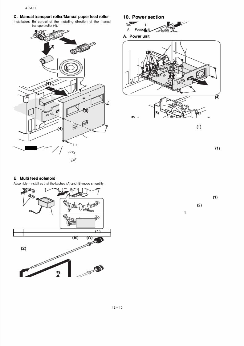
7/27/2019 Sharp Ar 160 & 161ar-161 Service Manual
http://slidepdf.com/reader/full/sharp-ar-160-161ar-161-service-manual 64/67
D. Manual transport roller/Manual paper feed rollerInstallation: Be careful of the installing direction of the manual
transport roller (4).
E. Multi feed solenoid
Assembly: Install so that the latches (A) and (B) move smoothly.
10. Power section
No. Content
A Power unit
A. Power unit
LC
K
T O
K O
(2)
(3)
(1 )
(4)
(5)
(2)
(1 )
(2)
(A)(B)
(3)
(4)
(5)
(3)
(3)
(4)
(2)
(1 )
(1 )
(1 )
1
AR-161
12 – 10

7/27/2019 Sharp Ar 160 & 161ar-161 Service Manual
http://slidepdf.com/reader/full/sharp-ar-160-161ar-161-service-manual 65/67
11. Developing section
No. Contents
A Waste toner box
B Developing box
C Developing doctor
D MG roller
A. Waste toner box
B. Developing box
C. Developing doctor
Adjustment: Developing doctor gap adjustment
D. MG roller
Adjustment: MG roller main pole position adjustment
(1 )
(1 )
(2)
(1 )
(2)
(1 )
(2)
(1 )
(1 )
(2)
1
(3)
(4)
(5)
(6)
(3)
AR-161
12 – 11

7/27/2019 Sharp Ar 160 & 161ar-161 Service Manual
http://slidepdf.com/reader/full/sharp-ar-160-161ar-161-service-manual 66/67
12. Process section
No. Contents
A Drum unit
B MC holder unit
C Cleaning blade
A. Drum unit
Assembly: When installing the drum cover (1), be sure to engage thetransport screw gear (A) rib and the detection gear (B).
B. MC holder unit
C. Cleaning blade
(1 )
L O C K
(A)
(B)
L O C K
(2 )
(3)
(2)
(1 )
(1 )
(2)
(1 )
(1 )
AR-161
12 – 12

7/27/2019 Sharp Ar 160 & 161ar-161 Service Manual
http://slidepdf.com/reader/full/sharp-ar-160-161ar-161-service-manual 67/67
qCOPYRIGHT © 1998 BY SHARP CORPORATION
All rights reserved.Printed in Japan.
No part of this publication may be reproduced,stored in a retrieval system, or transmitted,
in any form or by any means,electronic, mechanical, photocopying, recording, or otherwise,without prior written permission of the publisher.
SHARP CORPORATIONPrinting & Reprographic Systems GroupQuality & Reliability Control CenterYamatokoriyama, Nara 639-1186, Japan
1998 December Printed in Japan N
AR-161
AR-160/161 FM/E COVER 12/1/1998