Shamil Baldeosingh Dasney Joseph Walter McKinley March 4 th, 2010 EML 4905 Senior Design Project...
19
Design of Small Chemical Vapor Deposition System for Materials Research Application Shamil Baldeosingh Dasney Joseph Walter McKinley March 4 th , 2010 EML 4905 Senior Design Project Advisor: Dr. K. H. Wu March 24, 2010 1
-
Upload
percival-parker -
Category
Documents
-
view
214 -
download
0
Transcript of Shamil Baldeosingh Dasney Joseph Walter McKinley March 4 th, 2010 EML 4905 Senior Design Project...

1
Design of Small Chemical Vapor Deposition System
for Materials Research Application
Shamil Baldeosingh Dasney Joseph
Walter McKinley
March 4th , 2010
EML 4905 Senior Design ProjectAdvisor: Dr. K. H. WuMarch 24, 2010

2
Overview
Background Problem Statement Design Specifications Conceptual Designs Project Management Future Plans

3
Chemical Vapor Deposition for Carbon Nanotube (CNT) Synthesis
Chemical Vapor Deposition ( CVD )
Widely used for engineering applications
• Scalable to industrial production• 20-100 % yield
• Controllable parameters to determine properties

4
What Are Carbon Nanotubes?
Large Research Interest
Properties• Mechanical• Electrical • Thermal• Novel Applications
Variations• Dimensions and Geometry• Quality and Yield
Zhao et al., Physical Review Letters,

5
Problem Statement
CNT synthesis for current CVD system 3 hours for sample size of 1 – 5 grams
▪ Furnace heating of entire reaction chamber▪ Such a large sample size is not necessary for
research
CNT synthesis for proposed CVD system 0.5 hours for sample size of less than 1
gram▪ Localized heating of gases and substrate▪ Appropriate for research applications

6
System Constraints
Preheated Gas Temperature• At least 400 Ac
Substrate Temperature• 600-1000 Ac
Volumetric flow Rate (mL/min)
PROCESS GAS Hydrogen (H2) 400PRECURSOR
GAS Acetylene (C2H2) 100
CARRIER GAS Argon (Ar) 600
7
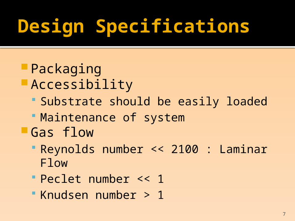
Design Specifications
Packaging Accessibility
Substrate should be easily loaded Maintenance of system
Gas flow Reynolds number << 2100 : Laminar
Flow Peclet number << 1 Knudsen number > 1

8
Conceptual Design AUniform Diameter Tube

9
Conceptual Design B Variable Diameter Tube

10
Conceptual Design C Modular Cube

11
Comparison of Conceptual Designs
Design AStraight Tube
Design BVariable Cross Section Tube
Design CCube
Packaging 4 4 1
Accessibility
5 5 1
Gas Flow 3 2 4
Price 1 2 5
Excellent – 1 Very Good -2 Good – 3 Fair – 4Poor - 5

12
Heating Considerations
Substrate Material• Wafer • Powder
Resistive Heating Element• Material• Configurations• Life span
Thermal Strength• Thermal Shock• Thermal Expansion• Deflection
Power Input• AC vs. DC• H-Current/ L-Voltage• L-Voltage/H-Current

13
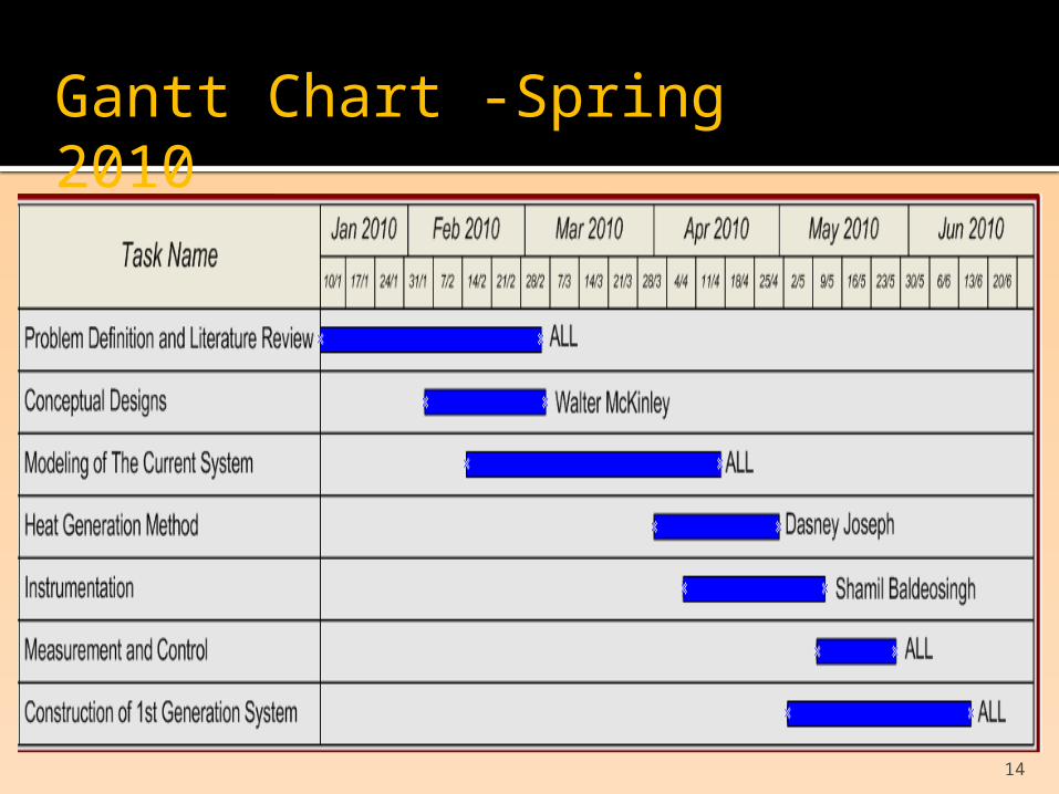
Division of Responsibility
Heat Generation Dasney Joseph
Instrumentation and Fluid Mechanics Shamil Baldeosingh
Conceptual Designs and Prototype Walter McKinley
14
Gantt Chart -Spring 2010

15
Gantt Chart - Fall 2010

16
Human Cost
0
5
10
15
20
25
January February March April
TIME (hours)
SHAMIL DASNEY WAL-TER

17
Future Work
Design Modeling• SolidWorks
Simulation• ANSYS CFX
▪ Fluid Mechanics▪ Heat Transfer from
Resistive Heating Elements
Instrumentation and Control• LabVIEW• Thermocouple• Infrared Temperature
Sensor• Mass Flow Controller
Prototype Testing• Scanning Electron
Microscope ( SEM ) ▪ Verify growth of CNT’s

18
Acknowledgments
Dr. Wu ( Florida International University ) Amit Datye ( Oak Ridge National
Laboratory ) John Hart ( Massachusetts Institute of
Technology )

19
Questions & Comments