![BOUNDEDNESS OF MAXIMAL OPERATORS AND OSCILLATION … › reports › a585.pdf · introduction to analysis on metric spaces we refer to [22]. In this overview, we first introduce](https://static.fdocuments.in/doc/165x107/5f149bcc3832cc6b26000345/boundedness-of-maximal-operators-and-oscillation-a-reports-a-a585pdf-introduction.jpg)
SFC332GM OPERATORS MANUAL - Dynamic...
106
Date: 2/12/2016 SFC332GM OPERATORS MANUAL Flow Computer GAS Metric Version 11104 W.Airport Blvd, Suite 108 & 148 Stafford, Texas 77477 USA (281) 565-1118 Fax (281) 565-1119
Transcript of SFC332GM OPERATORS MANUAL - Dynamic...

Date: 2/12/2016
SFC332GM
OPERATORS MANUAL Flow Computer
GAS Metric Version
11104 W.Airport Blvd, Suite 108 & 148
Stafford, Texas 77477 USA
(281) 565-1118
Fax (281) 565-1119

Date: 2/12/2016
WARRANTY
Dynamic Flow Computers warrants to the owner of the Flow Computer that the product
delivered will be free from defects in material and workmanship for one (1) year
following the date of purchase.
This warranty does not cover the product if it is damaged in the process of being installed
or damaged by abuse, accident, misuse, neglect, alteration, repair, disaster, or improper
testing.
If the product is found otherwise defective, Dynamic Flow Computers will replace or
repair the product at no charge, provided that you deliver the product along with a return
material authorization (RMA) number from Dynamic Flow Computers.
Dynamic Flow Computers will not assume any shipping charge or be responsible for
product damage due to improper shipping.
THE ABOVE WARRANTY IS IN LIEU OF ANY OTHER WARRANTY EXPRESS
IMPLIED OR STATUTORY. BUT NOT LIMITED TO ANY WARRANTY OF
MERCHANTABILITY, FITNESS FOR PARTICULAR PURPOSE, OR ANY
WARRANTY ARISING OUT OF ANY PROPOSAL, SPECIFICATION, OR SAMPLE.
LIMITATION OF LIABILITY:
DYNAMIC FLOW COMPUTERS SHALL HAVE NO LIABILITY FOR ANY
INDIRECT OR SPECULATIVE DAMAGES (INCLUDING, WITHOUT LIMITING
THE FOREGOING, CONSEQUENTIAL, INCIDENTAL AND SPECIAL DAMAGES)
ARISING FROM THE USE OF, OR INABILITY TO USE THIS PRODUCT.
WHETHER ARISING OUT OF CONTRACT, OR UNDER ANY WARRANTY,
IRRESPECTIVE OF WHETHER DFM HAS ADVANCED NOTICE OF THE
POSSIBILITY OF ANY SUCH DAMAGE INCLUDING, BUT NOT LIMITED TO
LOSS OF USE, BUSINESS INTERRUPTION, AND LOSS OF PROFITS.
NOTWITHSTANDING THE FOREGOING, DFM’S TOTAL LIABILITY FOR ALL
CLAIMS UNDER THIS AGREEMENT SHALL NOT EXCEED THE PRICE PAID
FOR THE PRODUCT. THESE LIMITATIONS ON POTENTIAL LIABILITY WERE
AN ESSENTIAL ELEMENT IN SETTING THE PRODUCT PRICE. DFM NEITHER
ASSUMES NOR AUTHORIZES ANYONE TO ASSUME FOR IT ANY OTHER
LIABILITIES
Date: 2/12/2016
CHAPTER 1: QUICK START.................................................................................................................... 1-1 Introduction: ............................................................................................................................................ 1-1 Conventions Used in This Manual: ......................................................................................................... 1-1 Smart Flow Computer : Dimensions ....................................................................................................... 1-2 Website - DFM Configuration Software ................................................................................................. 1-2 Starting and Installing the Software: ....................................................................................................... 1-4
To run off the hard drive of a PC or laptop: ........................................................................................ 1-4 Technical Data ......................................................................................................................................... 1-5 POWER ................................................................................................................................................... 1-5 Parts List .................................................................................................................................................. 1-6 Getting acquainted with the flow computer wiring: ................................................................................ 1-7
Back terminal wiring: .......................................................................................................................... 1-7 Back Panel Jumper .............................................................................................................................. 1-8 Memory Jumper................................................................................................................................... 1-9
INPUT/OUTPUT: Assignment, Ranging, Wiring, and Calibration ..................................................... 1-11 Input/Output Assignment .................................................................................................................. 1-11 How to assign a transmitter to an I/O point: ...................................................................................... 1-11 Ranging the Transmitter Inputs: ........................................................................................................ 1-11
WIRING: ............................................................................................................................................... 1-13 Wiring the analog inputs: .................................................................................................................. 1-13 Wiring the analog inputs 1-4 : ........................................................................................................... 1-14 Wiring the analog inputs 5,6 : ........................................................................................................... 1-15 RTD ................................................................................................................................................... 1-16 Wiring Analog Output: ...................................................................................................................... 1-17 Turbine input wiring .......................................................................................................................... 1-18 Turbine input wiring for passive (dry contact) pulse generators ....................................................... 1-19 Density input wiring: ......................................................................................................................... 1-20 RS-232 connection: ........................................................................................................................... 1-21 RS-485: .............................................................................................................................................. 1-22 Wiring of status inputs: ..................................................................................................................... 1-23 Wiring of switch/pulse outputs: ......................................................................................................... 1-24 I/O Expansion: ................................................................................................................................... 1-25
Calibration ............................................................................................................................................. 1-28 Analog Input 4-20mA or 1-5 volt signal: .......................................................................................... 1-28 RTD calibration: ................................................................................................................................ 1-29 Calibration of analog output: ............................................................................................................. 1-30 Multi-Variable Transmitters (Model 205) – Dp and Pressure ........................................................... 1-31 Multi-Variable Transmitters (Model 205)- RTD ............................................................................... 1-32
Verifying Digital Inputs and Outputs: ................................................................................................... 1-33 CHAPTER 2: Data Entry ............................................................................................................................ 2-1
Introduction to the Smart Flow Computer Software................................................................................ 2-1 About ....................................................................................................................................................... 2-1 File ........................................................................................................................................................... 2-2
Open a File .......................................................................................................................................... 2-2 Open a New File(8 Chars.) .................................................................................................................. 2-2 Delete a File ......................................................................................................................................... 2-3 Load File.............................................................................................................................................. 2-3 View File ............................................................................................................................................. 2-3 Save As ................................................................................................................................................ 2-4 Save ..................................................................................................................................................... 2-4 Save and Exit ....................................................................................................................................... 2-4 Exit ...................................................................................................................................................... 2-4
PORT ....................................................................................................................................................... 2-5 PC Communication Set Up.................................................................................................................. 2-5 Flow Computer Communication Set Up ............................................................................................. 2-6

Date: 2/12/2016
SPI Ports .............................................................................................................................................. 2-7 Gas Chromatograph Communcation Set up ........................................................................................ 2-8 Dial ...................................................................................................................................................... 2-9 Phone Book ......................................................................................................................................... 2-9 Modem Setup .................................................................................................................................... 2-10 Hang-up Phone .................................................................................................................................. 2-10
DIAG ..................................................................................................................................................... 2-11 Read Single Flow Computer Communication Setup ......................................................................... 2-11 Diagnostic Data ................................................................................................................................. 2-11 Smart Flow Computer Configuration Diagram ................................................................................. 2-11
METER ................................................................................................................................................. 2-12 Meter Set Up ..................................................................................................................................... 2-12 Orifice Meter Data ............................................................................................................................. 2-13 Turbine Meter Data ........................................................................................................................... 2-15 Other Parameters ............................................................................................................................... 2-16 Calc . Parameters ............................................................................................................................... 2-17 Date and Time ................................................................................................................................... 2-19 Parameter Overrides .......................................................................................................................... 2-19 Security Code .................................................................................................................................... 2-19
INPUT/OUTPUT .................................................................................................................................. 2-20 Transducer Input Assignment ............................................................................................................ 2-20 Transducer Tag ID ............................................................................................................................. 2-21 Calibration ......................................................................................................................................... 2-21 Status Input Assignment .................................................................................................................... 2-22 Switch Output Assignment ................................................................................................................ 2-22 Analog Output Assignment ............................................................................................................... 2-24 Smart Flow Computer Display Assignment ...................................................................................... 2-25 Modbus Shift ..................................................................................................................................... 2-26
REPORTS ............................................................................................................................................. 2-27 Current Data - Snapshot Totalizer Updates ....................................................................................... 2-27 Previous Hourly Data ........................................................................................................................ 2-27 Previous Daily Data ........................................................................................................................... 2-27 Previous Monthly Data ...................................................................................................................... 2-27 Previous Alarm Data ......................................................................................................................... 2-27 Audit Trail Report ............................................................................................................................. 2-27 Build User Report .............................................................................................................................. 2-27 View User Report .............................................................................................................................. 2-27 Formatted Ticket Report .................................................................................................................... 2-28 Ticket Report ..................................................................................................................................... 2-28 Auto Data Retrieval ........................................................................................................................... 2-28
WIRING ................................................................................................................................................ 2-29 PRINT ................................................................................................................................................... 2-30
Print "Help" File ................................................................................................................................ 2-30 Print Modbus Registers ..................................................................................................................... 2-30 Print Schematic .................................................................................................................................. 2-30 Print Calibration Data ........................................................................................................................ 2-30 Print Files .......................................................................................................................................... 2-30
CHAPTER 3: Flow Equations ..................................................................................................................... 3-1 Common Terms ....................................................................................................................................... 3-1 ISO5167................................................................................................................................................... 3-2 Mass Flow Rate (TON/HR) ..................................................................................................................... 3-2 Net Flow Rate (KM3/HR) ....................................................................................................................... 3-2 Gross Flow Rate (KM3/HR) .................................................................................................................... 3-2 Energy Flow Rate (GJ/HR) ..................................................................................................................... 3-2 API 14.3................................................................................................................................................... 3-3 AGA 7 ..................................................................................................................................................... 3-4

Date: 2/12/2016
Gross Flowrate (KM3/HR) ...................................................................................................................... 3-4
Net Flowrate (KSM3/HR) ....................................................................................................................... 3-4 Mass Flowrate (TON/HR) ....................................................................................................................... 3-4 Energy Flowrate (GJ/HR) ........................................................................................................................ 3-4 DENSITY EQUATIONS ........................................................................................................................ 3-5
Sarasota Density KG/M3 ..................................................................................................................... 3-5 UGC Density KG/M3 .......................................................................................................................... 3-6 Solartron Density GM/CC ................................................................................................................... 3-7 AGA8 Gross Method 1 ........................................................................................................................ 3-8 AGA8 Gross Method 2 ........................................................................................................................ 3-8 AGA8 Detail Method .......................................................................................................................... 3-8 Steam NBS Equation ........................................................................................................................... 3-8 Ethylene NBS1045 .............................................................................................................................. 3-8 Parahydrogen - NBS 1048 ................................................................................................................... 3-8 Oxygen - NBS 1048 ............................................................................................................................ 3-8 Nitrogen - NBS 1048 ........................................................................................................................... 3-8 Argon - NBS 1048 ............................................................................................................................... 3-8
CHAPTER 4: MODBUS DATA ................................................................................................................. 4-1 MODBUS PROTOCOL .......................................................................................................................... 4-1
TRANSMISSION MODE ................................................................................................................... 4-1 ASCII FRAMING ............................................................................................................................... 4-1 RTU FRAMING .................................................................................................................................. 4-1 FUNCTION CODE ............................................................................................................................. 4-2 ERROR CHECK ................................................................................................................................. 4-2 EXCEPTION RESPONSE .................................................................................................................. 4-2 BROADCAST COMMAND ............................................................................................................... 4-2 MODBUS EXAMPLES ...................................................................................................................... 4-3 Scaled Data Area ................................................................................................................................. 4-9 Last Daily or Monthly Data Area ...................................................................................................... 4-13 Last Hourly Data Area ....................................................................................................................... 4-23 Last Monthly Data Area .................................................................................................................... 4-24
Dynamic Flow Computers SFC332GM Gas Manual Data Entry — 1-1
Date: 2/12/2016
CHAPTER 1: QUICK START
Introduction: A good flow computer must be:
User friendly
Flexible
Easy to understand and configure
Rugged
Economical to install and maintain
Accurate
The model SFC332GM Smart Flow Computer incorporates all these features. We hope that your
experience with the Smart Flow Computer will be a very pleasant and friendly experience and not
intimidating in any way.
The SFC332GM is a dual stream, dual meter run flow computer with bi-directional capabilities. It includes
the following mass flow equations: old AGA3, API14.3, venturi, annubar, and turbine (AGA7).
Additionally, it can perform density calculations per these standard procedures: AGA8, NX19 for gas,
NBS1048 for hydrogen and oxygen, NBS for steam, NBS1045 for ethylene.
Two Rosemount multi-variable digital transducers can be used with each flow computer for temperature,
pressure (up to 3700 PSIG), and DP (up to 250 inches H2O).
The Smart Flow Computer has a host of inputs and outputs beyond its turbine inputs: 4 additional analog
inputs, two 4 wire RTD inputs, 2 analog outputs, RS-232 and RS-485 with Modbus protocol, 4 status inputs
and 5 switch and pulse outputs.
Additionally, each Smart Flow Computer can store up to 35 days of hourly and daily data, making it ideal
for unattended, accurate data logging.
Conventions Used in This Manual: <ENTER> the “enter” or “return” key on the PC keyboard
<ALT><D> hit the key (here, hold down <ALT> and strike <D>).
Set Up This type of text indicates a menu item in the software
Meter | Set Up | Common Pressure Two or more items in this font separated by a vertical bar
(bars) is used to indicate a menu item and sub item. In
this example, Meter is on the menu bar, Set Up is a
topic beneath it, and Common Pressure is listed in
turn beneath it.
Meter #[1/2] Use Stack DP The [1/2] is indicates that two menu items exist, one
for Meter #1 and one for Meter #2.
Note: A note has an important piece of information and is boxed to call attention to itself.
Dynamic Flow Computers SFC332GM Gas Manual Data Entry — 1-2
Date: 2/12/2016
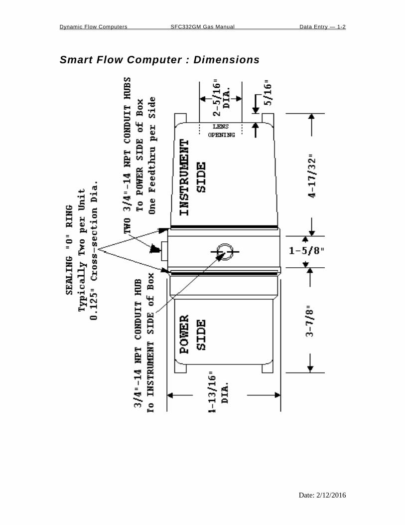
Smart Flow Computer : Dimensions
Dynamic Flow Computers SFC332GM Gas Manual Data Entry — 1-3
Date: 2/12/2016
Website - DFM Configuration Software
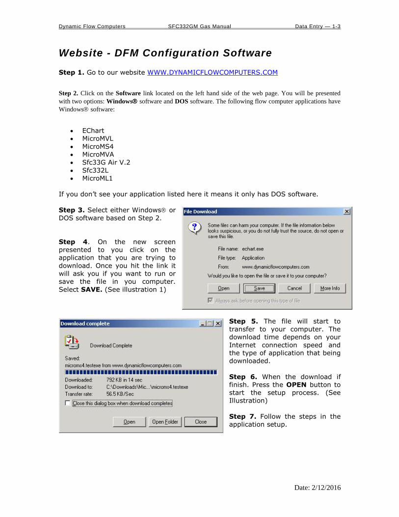
Step 1. Go to our website WWW.DYNAMICFLOWCOMPUTERS.COM
Step 2. Click on the Software link located on the left hand side of the web page. You will be presented
with two options: Windows software and DOS software. The following flow computer applications have
Windows software:
EChart
MicroMVL
MicroMS4
MicroMVA
Sfc33G Air V.2
Sfc332L
MicroML1
If you don’t see your application listed here it means it only has DOS software.
Step 3. Select either Windows or
DOS software based on Step 2.
Step 4. On the new screen
presented to you click on the
application that you are trying to
download. Once you hit the link it
will ask you if you want to run or
save the file in you computer.
Select SAVE. (See illustration 1)
Step 5. The file will start to
transfer to your computer. The
download time depends on your
Internet connection speed and
the type of application that being
downloaded.
Step 6. When the download if
finish. Press the OPEN button to
start the setup process. (See
Illustration)
Step 7. Follow the steps in the
application setup.

Dynamic Flow Computers SFC332GM Gas Manual Data Entry — 1-4
Date: 2/12/2016
Starting and Installing the Software: To acquaint you with your software we will begin the software, create a new configuration file, and save it.
We describe this procedure as though you are running the software from a floppy disk. At the bottom of
the page we give you simple instructions for installing the software onto a PC’s hard drive.
1. Insert the diskette that is provided with the flow computer into your PC or laptop (3.5”
disk drive).
2. Call the drive by entering A: or B: depending on the drive you are using.
3. Type the instructions on the diskette (in this case SFC332GM) and then press <ENTER>.
4. The software opens ready for you to choose an existing file. The File | Open File
menu topic | subtopic are highlighted. However, we have not configured any files yet;
therefore use your arrow keys to move to Open New File and press <ENTER>.
5. Type in your new file’s name (eight alphanumeric characters or less) and then press
<ENTER>.
6. Now you are back to Open New File. Use the down arrow key to move the cursor
to Save and press <ENTER>. You have just saved the file you just created. Notice that
now the file name will appears in the right top corner of the screen, on the menu bar.
This indicates the name of the currently active file; if you change parameters and Save
again, the changes will be saved to your file.
7. Use the right and left arrow keys to scroll through the menu. All menus have an on-line
help screen that appears when you push the <F1> key. Browse through the program
and use the help menu to understand the purpose for any particular entry. You will also
notice that there is a “prompt” line at the bottom of your screen. This prompts you for
appropriate key choices wherever you are in the program.
To run off the hard drive of a PC or laptop:
1. Create a subdirectory with a name of your choosing, for example, SFC.
2. Copy the contents of the floppy disk to directory SFC. In DOS this could be
accomplished with a command such as COPY A:*.* C:\SFC.
3. Launch the new copy of SFC332GM that now resides on your hard drive instead of the
version on your floppy disk.
If you decide to run your Smart Flow Computer software from a floppy disk it is a good idea to make a
copy of your original disk and run from the copy.

Dynamic Flow Computers SFC332GM Gas Manual Data Entry — 1-5
Date: 2/12/2016
Technical Data
POWER
VOLTAGE RANGE 12-30 VDC
WATTAGE 4 WATT
OPERATING CONDITIONS
TEMPERATURE - 40 TO 185 °F
HUMIDITY 100%
HOUSING NEMA 4X CLASS 1 DIV. 1
FEATURES
DISPLAY PLASMA 2 LINES 16 CHARACTER
PROCESSOR 32-BIT MOTOROLA 168332 @ 16.7 MHz
FLASH ROM 4 MB @ 70 NANO SECONDS
ROM 2 MB @ 30 NANO SECONDS
FREQUENCY INPUT 3 CHANNELS 0 - 5000 Hz
>70 mV FOR SIN WAVE > 6 VOLTS FOR SQUARE WAVE
ANALOG INPUT FOUR 24-BIT CHANNEL
RTD INPUTS 2 CHANNELS 4 WIRES
ANALOG OUTPUT 2 CHANNELS 12 BIT SINGLE ENDED
DIGITAL OUTPUT OUTPUTS 1 & 2 PULSE/SWITCH 0.5 AMPS RATING OUTPUTS 3 TO 5 ARE SWITCH OUTPUTS 0.25 AMPS
RATING
STATUS INPUTS 4 ON/OFF TYPE SIGNAL
ALL INPUTS AND OUTPUTS ARE OPTICALLY ISOLATED
SERIAL 1 RS485 @ 38400 BAUDS VARIABLE 1 RS232 @ 19200 BAUDS VARIABLE
COMMUNICATION PROTOCOL MODBUS
Dynamic Flow Computers SFC332GM Gas Manual Data Entry — 1-6
Date: 2/12/2016
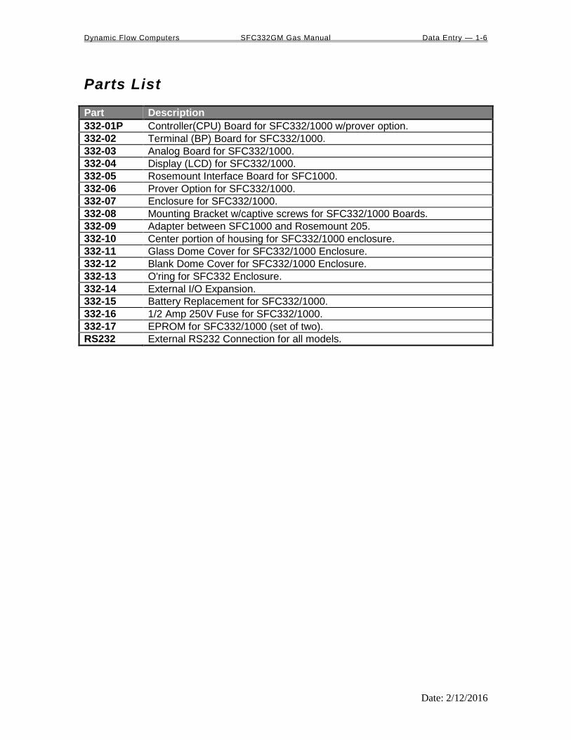
Parts List
Part Description
332-01P Controller(CPU) Board for SFC332/1000 w/prover option.
332-02 Terminal (BP) Board for SFC332/1000.
332-03 Analog Board for SFC332/1000.
332-04 Display (LCD) for SFC332/1000.
332-05 Rosemount Interface Board for SFC1000.
332-06 Prover Option for SFC332/1000.
332-07 Enclosure for SFC332/1000.
332-08 Mounting Bracket w/captive screws for SFC332/1000 Boards.
332-09 Adapter between SFC1000 and Rosemount 205.
332-10 Center portion of housing for SFC332/1000 enclosure.
332-11 Glass Dome Cover for SFC332/1000 Enclosure.
332-12 Blank Dome Cover for SFC332/1000 Enclosure.
332-13 O'ring for SFC332 Enclosure.
332-14 External I/O Expansion.
332-15 Battery Replacement for SFC332/1000.
332-16 1/2 Amp 250V Fuse for SFC332/1000.
332-17 EPROM for SFC332/1000 (set of two).
RS232 External RS232 Connection for all models.

Dynamic Flow Computers SFC332GM Gas Manual Data Entry — 1-7
Date: 2/12/2016
Getting acquainted with the flow computer wiring:
To wire the flow computer, get familiar with the drawings provided in the software’s Wiring menu. Use
the arrow left and right keys to move to and select Wiring, and then press <ENTER>.
Back terminal wiring: The back terminal wiring indicates the overall positions of the terminal plugs and their functions. Though
the back panel’s jumpers are also shown, refer to the next drawing, “Back Panel Jumpers”, for information
on their settings and functions.
The Smart Flow Computer receives its power via the two topmost pins on Terminal P1, on the left of the
terminal board. Also on Terminal P1 are, from top to bottom, inputs from the two turbines and the RS-485
serial connection.
To the right (P4), from top to bottom, is status input 1, density frequency input, and switch output 1 and 2.
Terminal P3, at the lower bottom, handles analog inputs and outputs. These are, in order from right to left,
analog inputs 1-4 and analog outputs 1 and 2.
Terminal P5, top middle, is the RTD terminal block, "100 platinum RTD input".

Dynamic Flow Computers SFC332GM Gas Manual Data Entry — 1-8
Date: 2/12/2016
Back Panel Jumper In this illustration, a jumper is “ON” when the jumper block is used to connect the jumper’s to wire prongs.
“OFF” means the jumper block is completely removed or attached to only one of the two wire prongs.
Note: R11 and R3 could have a vertical orientation instead of a horizontal orientation on certain Smart Flow Computer models.
Dynamic Flow Computers SFC332GM Gas Manual Data Entry — 1-9
Date: 2/12/2016
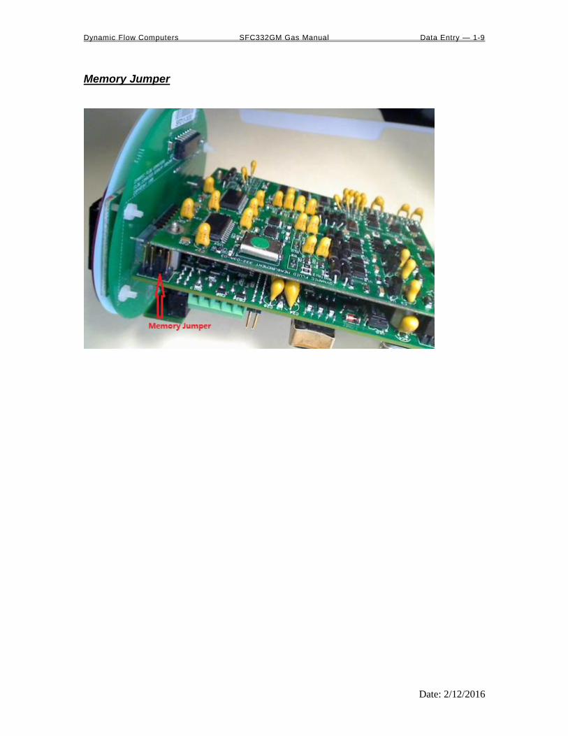
Memory Jumper

Dynamic Flow Computers SFC332GM Gas Manual Data Entry — 1-10
Date: 2/12/2016
Steps to clear memory through removing the memory jumper
(1) Turn off the power, move the jumper to the next two pins, wait for 5 seconds
(2) Put the jumper back
Memory cleared and Flow Computer ID is set to 1, 9600 baud rate, RTU mode

Dynamic Flow Computers SFC332GM Gas Manual Data Entry — 1-11
Date: 2/12/2016
INPUT/OUTPUT: Assignment, Ranging, Wiring, and Calibration
Input/Output Assignment We will now configure your Smart Flow Computer’s inputs and outputs. The flow computer allows the
user to configure the inputs and outputs. i.e. Analog #1 is pressure for Meter #1. Unassigned inputs are not
used by the flow computer.
How to assign a transmitter to an I/O point: Before beginning the procedure of assigning inputs and outputs, it is advisable to set up the meter (Meter
| Set Up). This is because certain parameters on the Transducer Input Assignment page
change (or may not appear, etc.) based on Meter | Set Up.
1 Use your arrow keys to scroll to menu item I/O (between Meter and Report). Its first
entry is Transducer Input Assignment. Press <ENTER>.
2. Use the down/up arrow key to scroll through this menu. The first four parameters are used to
set the number of decimals you would like to see in your live inputs (these numbers do not
affect the precision of your calculated data). Spare inputs are inputs that the flow computer
will read and display in the diagnostic data but are not used in the calculations. Spare inputs
high and low limit alarms are documented in the historical alarm report.
3. After the parameters used for setting the number of decimals come a series of parameters
ending with the words Assignment (1-n). Assignments 1-4 are analog
inputs attached to terminal P3 of the back panel. These
inputs accept 4-20mA or 1-5 volts input and are suitable for temperature, pressure,
density, BS&W, or spare inputs. Assignments 5 and 6 are strictly RTD (temperature) inputs
only for the meter, prover, densitometer or spare; temperatures are inputted via terminal P5
on the back panel. Assignment 7 indicates a density frequency input; it is assigned
automatically once you choose live density frequency input in the setup menu at density type
selection (and it can only be assigned via Meter | Set Up | Density #n, where n = 1 to
4). Assignment 10 (module 1) and assignment 11 (module 2) are used for Rosemount multi-
variable module only. DP, pressure, and temperature for the meter can be assigned.
Ranging the Transmitter Inputs:
1. Enter the range values: after assigning the inputs scroll down the transducer inputs
assignment menu to scale the 4-20mA. Enter the value at …@4mA and …@20mA. Enter both
values similar to the way the transmitter is ranged. 1-5 volts is equivalent to 4-20mA. Enter
the 1 volt value at the 4mA, and 5 volt value at 20mA.
2. Enter the high and low limits: high limits and low limits are simply the alarm points in
which you would like the flow computer to flag as an alarm condition. Enter these values
with respect to the upper and lower range conditions. Try to avoid creating alarm log when
conditions are normal. For example: If the line condition for the pressure is between 0 to 500
PSIG. Then you should program less than zero for low-pressure alarm, and 500 or more for
high-pressure alarm. High and low limits are also used in the scale for the Modbus variables.
3. Set up the fail code: Maintenance and Failure Code values tell the flow computer
to use a default value in the event the transmitter fails. The default value is stored in
Maintenance. There are three outcomes: the transmitter value is always used, no matter
what (Failure Code = 0); the Maintenance value is always used, no matter what

Dynamic Flow Computers SFC332GM Gas Manual Data Entry — 1-12
Date: 2/12/2016
(Failure Code = 1); and the Maintenance value is used only when the transmitter’s
value indicates that the transmitter has temporarily failed (Failure Code = 2).
RTD inputs will skip 4-20mA assignments because RTD is a raw signal of 50 (ohms) to 156. Readings
beyond that range require a 4-20mA signal to the flow computer.
Density coefficients for raw frequency inputs are programmed in this menu. The menu will only show
parameters relevant to the live density selected (i.e., Solartron or UGC, etc.).
NOTE: Solartron density input requires values in US units, i.e. PSI, and
F. Request a calibration sheet in US units from the densitometer manufacturer.

Dynamic Flow Computers SFC332GM Gas Manual Data Entry — 1-13
Date: 2/12/2016
WIRING: Wiring to the flow computer is very straightforward and simple. But still it is very important to get familiar
with the wiring diagram.
Wiring the analog inputs: Use your arrow keys to move the cursor to the menu item Wiring and then use up/down arrow keys to
select Analog Wiring. Press <ENTER>. Typical wiring for analog inputs 1 and 2 are shown in the
drawing. Analog inputs 3 and 4 are to the left of analog 1 and 2. Note that the analog input has only one
common return which is the -ve signal of power supply powering the transmitters.
When wiring 1-5 volts, make sure to calibrate the flow computer for the 1-5 volt signal because the flow
computer calibration defaults for the 4-20mA which is different from the 1-5 volts. JP5 must be cut for 1-5
volt inputs. The jumpers for analog 1-4 are in order from right to left. It is possible to cut the first two
jumpers for analog 1 & 2 in for 1-5 volts signal and have analog in 3 & 4 as 4-20mA signal. Signal line
impedance provided by our flow computer is less than 250. Therefore, when using a smart transmitter
that requires a minimum of 250 resistance in the loop, an additional resistor at the flow computer end
needs to be installed in series with the 4-20mA loop in order to allow the hand held communicator to talk to
the transmitter.
NOTE: The 4-20mA or 1-5 volt DOES NOT source power to the transmitters. You can use the DC power feeding the flow computer to power the 4-20mA loop IF that power
supply is FILTERED.

Dynamic Flow Computers SFC332GM Gas Manual Data Entry — 1-14
Date: 2/12/2016
Wiring the analog inputs 1-4 :

Dynamic Flow Computers SFC332GM Gas Manual Data Entry — 1-15
Date: 2/12/2016
Wiring the analog inputs 5,6 : The ‘Flow Computer’ can be configured as ‘6 analog inputs’ or ‘4 analog inputs and 2 RTD inputs’. (Under
IO Assignment Data Entry – SFC version 3.16, FC version 3.07 and higher)
When RTD is connected, make sure that 115 OHM is installed per drawing.

Dynamic Flow Computers SFC332GM Gas Manual Data Entry — 1-16
Date: 2/12/2016
RTD When ‘Flow Computer’ is configured as 4 analog inputs and 2 RTD inputs, go to the wiring menu where it
says RTD and press <ENTER>. The flow computer shows wiring to RTD 1 and RTD 2. 100 platinum
can be used; a temperature range of -43F to +300F can be measured. RTD 1 is to the right where P5
designation is. In the figure below notice that each side of the RTD requires two wire connections. When
using less than 4 wires a jumper must be used to make up for the missing lead. Internal excitation current
source generated is approximately 7mA. .

Dynamic Flow Computers SFC332GM Gas Manual Data Entry — 1-17
Date: 2/12/2016
Wiring Analog Output: The analog outputs are located on the left side of P3 connector. Go to the wiring diagram and scroll down
to Analog Output and press <ENTER>. Wiring diagram shows typical Analog output wiring. Notice
that analog output will regulate 4-20mA current loop but DOES NOT source the power for it. External
power is required.
ASSIGNING /RANGING THE 4-20MA ANALOG OUTPUTS :
Go to the I/O assignment main menu and scroll to Analog Output Assignment. Press
ENTER. A selection menu is prompted. Select the analog output number and then enter what the 4mA
output will indicate and the 20mA. Make sure that the 20mA assignment value exceeds the upper range
limit of what you assigned the Analog output for, otherwise the analog output will not update beyond
20mA.

Dynamic Flow Computers SFC332GM Gas Manual Data Entry — 1-18
Date: 2/12/2016
Turbine input wiring Scroll to Turbine under Wiring and press <ENTER>. Two drawings above each other will show
typical wiring for turbine meter 1 and turbine meter 2. When dual pick ups from the same turbine are
connected, use the inputs for turbine 1 for pickup 1 and turbine 2 for the second pickup coil. When
connecting sine wave directly from the pickup coil make sure the distance from the pickup coil to the flow
computer is very short--less than 50 feet with shielded cable. In the event there is presence of noise, the
distance must be shortened. When connecting sine wave signal, the R11 jumper for meter 1 must be
installed and R3 jumper for meter 2 must be installed. (JP3 and JP2 must be off when using sine wave).
On the other hand, when using square wave, the square wave signal can be sinusoidal but has to be above 5
volts peak to peak with less than 0.4 volts offset in order for the flow computer to read it. R11 and R3 must
be off and JP3 on for meter 1; JP2 must be on for meter 2.
Note: When connecting square wave input, the JP3 and JP2 connect the turbine return to the flow computer power return. Therefore, signal polarity is very important. Reverse polarity could result in some damage or power loss. When sine wave is used the signal polarity is usually of no significance.
The turbine input is immediately under the power input on terminal P1. The third pin down from the top is
Turbine/PD "minus", and below it is Turbine plus. The second pulse input for Turbine/PD meter 2 or the
second pickup coil is below turbine one input on P1. The fifth pin down from the top is turbine 2 "minus"
signal and below it is Turbine/PD 2 plus signal.
Note : R11 and R3 are oriented vertically in some flow computers.

Dynamic Flow Computers SFC332GM Gas Manual Data Entry — 1-19
Date: 2/12/2016
Turbine input wiring for passive (dry contact) pulse generators
Some mass flow meters have pulse outputs that do not provide power but instead require external power, they are referred to as passive outputs, dry outputs, open collector, etc. (For example the Krohne UFM 3030 Mass meter). In these cases the wiring should be as shown on the below diagram. The pull up resistor can be adjusted to limit the current sink by the Mass meter. For Turbine Input 1 JP3 must be ON and R11 OFF and if using Turbine Input 2 then JP2 must be ON and R3 OFF.

Dynamic Flow Computers SFC332GM Gas Manual Data Entry — 1-20
Date: 2/12/2016
Density input wiring: When using a live densitometer input with frequency signal, the signal can be brought into the Smart Flow
Computer in its raw form. The Smart Flow Computer accepts a sine wave or square with or without DC
offset. Example for density wiring can be seen in the wiring diagram. Use the arrow keys to get to
Wiring | Density and press <ENTER>. Find two drawings, one with barrier and the other without.
Barriers are used for area classification. Notice that the RTD wiring is also drawn to show how to hook the
density RTD signal.
Note: When wiring the density input polarity is of significance and reverse polarity could result in some damage or power loss. The density signal is on connector P4, the third and fourth pin down from the top. The third pin down is density plus, the fourth down is density minus. When Density input is 4-20mA it should be connected as a regular 4-20mA signal to the analog input and not the density frequency input.
Dynamic Flow Computers SFC332GM Gas Manual Data Entry — 1-21
Date: 2/12/2016
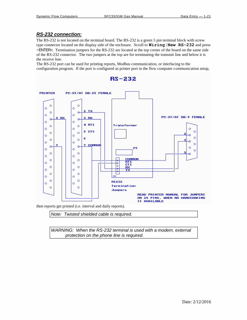
RS-232 connection: The RS-232 is not located on the terminal board. The RS-232 is a green 5 pin terminal block with screw
type connector located on the display side of the enclosure. Scroll to Wiring | New RS-232 and press
<ENTER>. Termination jumpers for the RS-232 are located at the top corner of the board on the same side
of the RS-232 connector. The two jumpers at the top are for terminating the transmit line and below it is
the receive line.
The RS-232 port can be used for printing reports, Modbus communication, or interfacing to the
configuration program. If the port is configured as printer port in the flow computer communication setup,
then reports get printed (i.e. interval and daily reports).
Note: Twisted shielded cable is required.
WARNING: When the RS-232 terminal is used with a modem, external protection on the phone line is required.

Dynamic Flow Computers SFC332GM Gas Manual Data Entry — 1-22
Date: 2/12/2016
RS-485: RS-485 wiring is shown in the wiring diagram under RS-485. The RS-485 termination jumper is JP4
located on the back terminal. The maximum distance when 18 gauge wire is used would be 4000 feet.
Note: Twisted shielded cable is required.
WARNING: When the RS-485 terminal is used, external transient protection and optical isolation is required, especially for long distance wiring.

Dynamic Flow Computers SFC332GM Gas Manual Data Entry — 1-23
Date: 2/12/2016
Wiring of status inputs: There is one status input standard and an optional three more on the back of the CPU board. The standard
status input is shown in the wiring diagram under Status Input. It has 4 volts of noise hysteresis,
with a trigger point of 5 volts and an off point of 1 Volt. Status inputs 2, 3, and 4 require the I/O expansion
connector and its wires be installed; refer to wiring drawing IO-Exp. Connection numbers 6, 7, and 8 are
the status in (positive) for inputs 2, 3, and 4, respectively, and 11 is the return for all three inputs.
Dynamic Flow Computers SFC332GM Gas Manual Data Entry — 1-24
Date: 2/12/2016
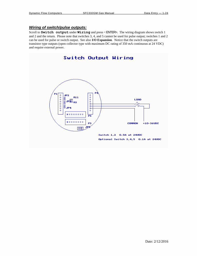
Wiring of switch/pulse outputs: Scroll to Switch output under Wiring and press < ENTER>. The wiring diagram shows switch 1
and 2 and the return. Please note that switches 3, 4, and 5 cannot be used for pulse output; switches 1 and 2
can be used for pulse or switch output. See also I/O Expansion. Notice that the switch outputs are
transistor type outputs (open collector type with maximum DC rating of 350 mA continuous at 24 VDC)
and require external power.

Dynamic Flow Computers SFC332GM Gas Manual Data Entry — 1-25
Date: 2/12/2016
I/O Expansion:
The I/O expansion is 16-pin connector next to the RS-232 terminal. Eleven pins of the 16-pin connector
are utilized. When the flow computer is ordered with the I/O expansion feature, the wires and the plug are
provided with the flow computer. There will be 11 wires with the wire number tag at the outer end of the
wire. The tag will indicate the wire number. The following is the sequence for the wires. On the top right
edge of the connector towards the top outer side of the CPU board is pin 1, across from it is pin 9.
Connection Purpose Comments 1 Detector switch 1 Requires prover option CPU to operate.
Rating: 5-36 Vdc 2 Detector switch 2
3 Switch output 3 Maximum rating: 75mA @24 volts Range: 5-36 Vdc
4 Switch output 4
5 Switch output 5
6 Status input 2
Rating: 6-36 Vdc 7 Status input 3
8 Status input 4
9 Return: detector switches
10 Return: switches 3, 4, 5
11 Return: status 2, 3, and 4

Dynamic Flow Computers SFC332GM Gas Manual Data Entry — 1-26
Date: 2/12/2016
I/O Expansion

Dynamic Flow Computers SFC332GM Gas Manual Data Entry — 1-27
Date: 2/12/2016
Prover/Expansion Connection No. Purpose Comments
1 Detector switch 1 Requires prover option CPU to operate. Rating: 5-36 Vdc 2 Detector switch 2
3 Switch output 3 Maximum rating: 75mA @24 volts Range: 5-36 Vdc
4 Switch output 4
5 Switch output 5
6 Status input 2
Rating: 6-36 Vdc 7 Status input 3
8 Status input 4
9 Return: detector switches
10 Return: switches 3, 4, 5
11 Return: status 2, 3, and 4
12 RS232 TX
13 RS232 RX
14 RS232 RTS
15 RS232 ret

Dynamic Flow Computers SFC332GM Gas Manual Data Entry — 1-28
Date: 2/12/2016
Calibration
Analog Input 4-20mA or 1-5 volt signal: Calibrations are performed under I/O | Calibration. Use the arrow keys to scroll to
Calibration and press <ENTER>. After you press <ENTER> the screen should show
COMMUNICATION STATUS : OK.
OFFSET CALIBRATION :
For simple offset type calibration simply induce the signal into the analog input and make sure the flow
computer is reading it. After you verify that the flow computer recognized the analog input press <F8>.
The screen will freeze. Scroll down to the analog input you are calibrating and enter the correct mA
reading. Then press <ENTER> followed by <F3> to download. The screen will stay in the freeze mode. To
bring the live readings press <F2> and then the flow computer will display the new calibrated readings.
The offset type calibration is mainly used when a small offset adjustment needs to be changed in the full
scale reading. The offset will apply to the zero and span.
FULL CALIBRATION METHOD:
To perform full calibration be prepared to induce zero and span type signal.
1. Induce the low end signal i.e. 4mA in the analog input.
2. Press <F8> and scroll down to the reading then press <ALT><R>(alternate key and the letter
R simultaneously). Then immediately enter the analog input value i.e. 4mA. Follow that by
<ENTER> and the download <F3> button.
3. Now be ready to enter the full scale value. Simply induce the analog signal and then enter the
value i.e. 20mA, and then download by pressing <ENTER> then <F3>.
4. Now induce live values to verify the calibration.
DEFAULT CALIBRATION
Simply press <F8> and scroll to the analog Input and press <ALT><R> followed by <F3 function key.
Dynamic Flow Computers SFC332GM Gas Manual Data Entry — 1-29
Date: 2/12/2016
RTD calibration: For offset calibration simply go to I/O | Calibration and press <ENTER>. Once the flow
computer shows communication status OK press <F8> and scroll to RTD 1 or RTD 2. RTD Calibration
is a 2-step process. The first step is a one time procedure to verify transducer linearity and is done at the time the meter is being setup. The second step is the routine calibration sequence. Step 1 – Linearity Verification 1. Use a Decade box with 0-150 °F settings. 2. Connect RTD cable to this resistive element for verification of linearity. Verify low and high points. It must be within ½ degree. 3. Connect the actual RTD element and compare with a certified thermometer. 4. If not within ½ degree do a Full Calibration (See Full Calibration below). If problem persists verify other elements such as RTD Probe, connections, shield, conductivity of connectors, etc. The purpose of the above procedure is to verify zero and span and make sure that the two points fall within the expected tolerance. Step 2 – Routine Calibration Once Linearity has been verified through Step 1, the routine calibration procedure is reduced to simply connecting the actual RTD and doing an offset point calibration (see offset calibration below). Calibration after that will be simple verification for the stability of the transmitter. If it drifts abnormally then you need to verify the other parts involved. RESET TO DEFAULT CALIBRATION
To go back to the default calibration simply press <F8> and scroll to the RTD input, and press
<ALT> <R> key followed by <F3> function key.
OFFSET CALIBRATION:
For offset calibration simply go to I/O | Calibration and press < ENTER>. Once the flow
computer shows communication status OK press <F8> function key and scroll to RTD. Induce a
live value and wait for 10 seconds for the reading to stabilize. Then enter the live value followed by <F3> function key to download the direct reading. The value entered must be in ohms only. FULL SCALE CALIBRATION:
1. Prepare low range resistive input (i.e., 80) and High range resistive input (i.e., 120). Go to the calibration menu and press <F8> function key. Scroll to the RTD input you are calibrating and press <ALT> <R> (key <ALT> and the letter R at the same time). Induce the low end
(80) resistive signal and then wait 10 seconds and enter 80 followed by pressing the <F3> function key.
2. Induce higher range signal (120) and wait 10 seconds, then enter the number 120 ohm and
press the <F3> key.
3. Now verify the live reading against the flow computer reading.
Dynamic Flow Computers SFC332GM Gas Manual Data Entry — 1-30
Date: 2/12/2016
Calibration of analog output: To calibrate the analog output against the end device follow the following steps:
1. Go to the calibration menu and press <F8>. Scroll down to analog output and press <ENTER >
and then <ALT><R>. This will cause the flow computer to output the minimum possible
signal 3.25 mA. Enter the live output value reading in the end device i.e. 3.25 mA and press
<F3> function key. Now the flow computer will output full scale 21.75 mA. Enter the live
output i.e. 21.75 then press the <F3> function key.
2. Now verify the output against the calibration device.

Dynamic Flow Computers SFC332GM Gas Manual Data Entry — 1-31
Date: 2/12/2016
Multi-Variable Transmitters (Model 205) – Dp and Pressure
OFFSET CALIBRATION
1. Induce live value for temperature, pressure, or Spare
2. Go to Calibration - Multi-Variable menu.
3. Press <F8>, point to the value being calibrated, enter the correct value followed by
<ENTER>, then press <F3> function key to download data.
4. Now read induce live values to verify the calibration.
FULL SCALE CALIBRATIO N
1. Press <F8>. Scroll to the parameter to be calibrated, then press <ALT><R>.
2. Induce the low range signal, then press <ENTER> followed by <F3> function key.
3. Induce the low range signal, then press <ENTER> followed by <F3>.
4. Now verify the live reading against the flow computer reading.
TO USE DEFAULT CALIBRATION
1. Select Multivariable DP or pressure 2. Select Reset calibration method 3. Now verify the live reading against the flow computer reading

Dynamic Flow Computers SFC332GM Gas Manual Data Entry — 1-32
Date: 2/12/2016
Multi-Variable Transmitters (Model 205)- RTD Calibrations are performed under I/O | Calibration. Use the arrow keys to scroll to
Calibration-Multi-Variable and press < ENTER>. After you press < ENTER> the screen
should show COMMUNICATION STATUS : OK.
RTD Calibration is a 2-step process. The first step is a one time procedure to verify transducer linearity and is done at the time the meter is being setup. The second step is the routine calibration sequence. Step 1 – Linearity Verification 1. Use a Decade box with 0-150 °F settings. 2. Connect RTD cable to this resistive element for verification of linearity. Verify low and high points. It must be within ½ degree. 3. Connect the actual RTD element and compare with a certified thermometer. 4. If not within ½ degree do a Full Calibration (See Full Calibration below). If problem persists verify other elements such as RTD Probe, connections, shield, conductivity of connectors, etc. The purpose of the above procedure is to verify zero and span and make sure that the two points fall within the expected tolerance. Step 2 – Routine Calibration Once Linearity has been verified through Step 1, the routine calibration procedure is reduced to simply connecting the actual RTD and doing an offset point calibration (see offset calibration below). Calibration after that will be simple verification for the stability of the transmitter. If it drifts abnormally then you need to verify the other parts involved. RESET TO DEFAULT CALIBRATION
To go back to the default calibration simply press <F8> and scroll to the RTD input, and press
<ALT> <R> key followed by <F3> function key.
OFFSET CALIBRATION:
For offset calibration simply go to I/O | Calibration and press < ENTER>. Once the flow
computer shows communication status OK press <F8> function key and scroll to RTD. Induce a
live value and wait for 10 seconds for the reading to stabilize. Then enter the live value followed by <F3> function key to download the direct reading. The value entered must be in degrees only. FULL SCALE CALIBRATION:
1. Prepare low range resistive input (i.e., 80) and High range resistive input (i.e., 120). Go to the calibration menu and press <F8> function key. Scroll to the RTD input you are calibrating and press <ALT> <R> (key <ALT> and the letter R at the same time). Induce the low end
(80) resistive signal and then wait 10 seconds and enter the equivalent temperature in degrees followed by pressing the <F3> function key.
2. Induce Higher range signal (120) and wait 10 seconds, then enter the temperature degrees equivalent to 120 followed by pressing the <F3> function key.
3. Now verify the live reading against the flow computer reading.

Dynamic Flow Computers SFC332GM Gas Manual Data Entry — 1-33
Date: 2/12/2016
Verifying Digital Inputs and Outputs: Use the diagnostic menu. Scroll down by using the arrow keys to Diag | Diagnostic Data and
press <ENTER>. A live input and output is displayed. On the top of the screen pulse inputs and density
frequency input are shown. Compare the live value against the displayed value on the screen. Failure to
read turbine input could be a result of the preamp being bad or the jumper selection for sine and square
wave input are not in the right position. Refer to wiring diagram Wiring | Turbine for proper
turbine input wiring. Density input can be sine or square wave with or without DC offset. Minimum
accepted signal has to be greater than 1.2 volt peak to peak. Status input is shown below the frequency
input to the left of the screen. When the status input is on, the live diagnostic data will show ON.
Minimum voltage to activate the status is 7 volts with negative threshold of 2 volts. Switch outputs are to
the right of the status inputs. To activate the switch outputs to the on and off position press <F8> in the
diagnostic menu. After the screen freeze the cursor will point to switch output one. Use the space bar to
toggle the switch on/off and the <ENTER> key to advance to the next switch. To exit press <ESC>. The
switch outputs are open collector and require external voltage.
Dynamic Flow Computers SFC332GM Gas Manual Flow Equations — 2-1
Date: 2/12/2016
CHAPTER 2: Data Entry
and Configuration Menus
Introduction to the Smart Flow Computer Software
Your SFC332GM software is constructed around a menu-driven organization. Begin your SFC software
and, across the top of your screen, you see a bar like this:
This is called the menu bar. It consists primarily of series of topics–Port, Diag, and so forth. When
you move the cursor to a topic you will see a list–we will call it a menu list– of topics related to the main
topic on the menu bar.
At the bottom of the screen is the prompt bar. It informs you of appropriate actions that you can perform
while your cursor is at its present location. In this example:
you are informed that your valid choices are the four arrow (rignt, left,down, and up) keys, the <ENTER>
key, and the <F1> key.
Another important area of the screen is the filename area. This is the rightmost section of the menu bar; it
informs you what configuration file you are presently viewing and editing. In the example above, you are
editing the file . When you first begin the SFC sotware, however, it will display
because no file has yet been chosen. Until you choose a file to edit or view, by opening either an existing
file or a new one, you will not be able to move from the File menu item.
The center portion of the screen is simply called the viewing area. Here you view either various menu lists
or the prompt window associated with an item in a menu list after it is selected (that is, after you press
<ENTER>). When you are in a prompt window the message appears in the filename area.
Under certain conditions you will have a screen where the viewing area takes up the whole screen and the
menu and/or prompt bars disappear. Examples of these are: the wiring diagrams, the calibration windows,
and the Diag windows.
About Displays the version number of EPROM and PC configuration menu. Press <Esc> to Exit.
Dynamic Flow Computers SFC332GM Gas Manual Flow Equations — 2-2
Date: 2/12/2016
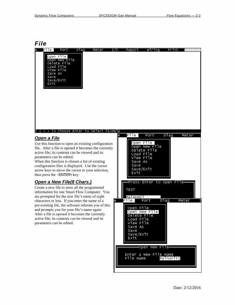
File
Open a File Use this function to open an existing configuration
file. After a file is opened it becomes the currently
active file; its contents can be viewed and its
parameters can be edited.
When this function is chosen a list of existing
configuration files is displayed. Use the cursor
arrow keys to move the cursor to your selection,
then press the <ENTER> key.
Open a New File(8 Chars.) Create a new file to store all the programmed
information for one Smart Flow Computer. You
are prompted for the new file’s name of eight
characters or less. If you enter the name of a
pre-existing file, the software informs you of this
and prompts you for your file’s name again.
After a file is opened it becomes the currently
active file; its contents can be viewed and its
parameters can be edited.
Dynamic Flow Computers SFC332GM Gas Manual Flow Equations — 2-3
Date: 2/12/2016
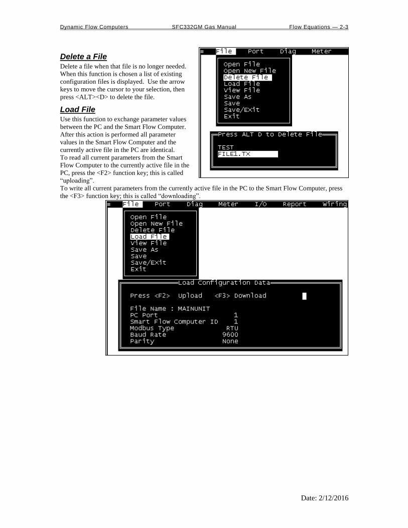
Delete a File Delete a file when that file is no longer needed.
When this function is chosen a list of existing
configuration files is displayed. Use the arrow
keys to move the cursor to your selection, then
press <ALT><D> to delete the file.
Load File Use this function to exchange parameter values
between the PC and the Smart Flow Computer.
After this action is performed all parameter
values in the Smart Flow Computer and the
currently active file in the PC are identical.
To read all current parameters from the Smart
Flow Computer to the currently active file in the
PC, press the <F2> function key; this is called
“uploading”.
To write all current parameters from the currently active file in the PC to the Smart Flow Computer, press
the <F3> function key; this is called “downloading”.

Dynamic Flow Computers SFC332GM Gas Manual Flow Equations — 2-4
Date: 2/12/2016
View File Unlike every other file function, View File does not act upon configuration files. Instead, View File allows
the user to view files that were previously captured in a report. For capturing data in a report, look for
these items under the Report menu header:
Prev. Hourly Data
Prev. Daily Data
Prev. Monthly Data
Alarm Data
Audit Trail Report
TicKet Report
Auto Data Retrieval
Current Data
When viewing a file use PageUp and PageDown to browse through it.
Save As Use Save As to save the parameters in the currently
active file (that is, the parameter values currently
being edited) to a new file. You are prompted for
the new file’s name of eight characters or less. If
you enter the name of a pre-existing file, the
software informs you of this and prompts you for your file’s name again.
The original file will remain in memory.
Save When permanent modifications are performed
on a file, user must save the new changes
before exiting the program, or proceeding to
open a different file.
Save and Exit Exit the program and save the parameters that
were changed.
Exit Exit without saving new modified parameters.
Dynamic Flow Computers SFC332GM Gas Manual Flow Equations — 2-5
Date: 2/12/2016
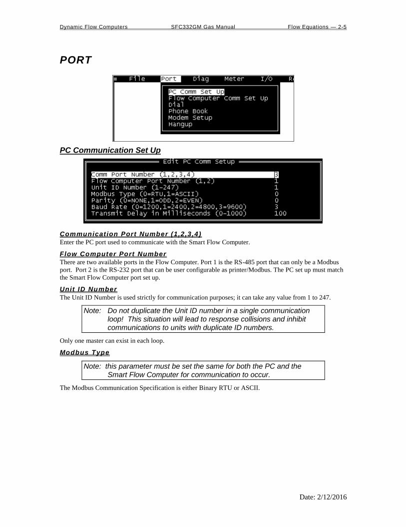
PORT
PC Communication Set Up
Communicat ion Port Number (1,2,3,4)
Enter the PC port used to communicate with the Smart Flow Computer.
Flow Computer Port Number
There are two available ports in the Flow Computer. Port 1 is the RS-485 port that can only be a Modbus
port. Port 2 is the RS-232 port that can be user configurable as printer/Modbus. The PC set up must match
the Smart Flow Computer port set up.
Unit ID Number
The Unit ID Number is used strictly for communication purposes; it can take any value from 1 to 247.
Note: Do not duplicate the Unit ID number in a single communication loop! This situation will lead to response collisions and inhibit communications to units with duplicate ID numbers.
Only one master can exist in each loop.
Modbus Type
Note: this parameter must be set the same for both the PC and the Smart Flow Computer for communication to occur.
The Modbus Communication Specification is either Binary RTU or ASCII.

Dynamic Flow Computers SFC332GM Gas Manual Flow Equations — 2-6
Date: 2/12/2016
Parity
Note: this parameter must be set the same for both the PC and the Smart Flow Computer for communication to occur.
0 = RTU - NONE
1 = ASCII - EVEN or ODD
Set the parity to match the Modbus Type.
Baud Rate
Note: this parameter must be set the same for both the PC and the Smart Flow Computer for communication to occur.
Baud rate is defined as number of bits per second. The available selections are 1200, 2400, 4800, or 9600.
Transmit Delay
This Delay in milliseconds is used to allow hand-shaking between the PC and the Smart Flow Computer.
The PC will hold the RTS line high for the specified Transmit Delay time. After that time expires the data
stream will begin transmitting. Transmit Delay is applicable regardless of the type of communication with
the Smart Flow Computer (RS-232 or RS-485).
This function can be very useful, especially when using a half-duplex RS-485 port; otherwise the RS-485
port will never turn off. A delay of 50 milliseconds is normally sufficient.
Flow Computer Communication Set Up
Unit ID Number
The Unit ID Number is used strictly for communication purposes; it can take any value from 1 to 247.
Note: Do not duplicate the Unit ID number in a single communication loop! This situation will lead to response collisions and inhibit communications to units with duplicate ID numbers.
Only one master can exist in each loop.
Port #1 Modbus Type
Note: this parameter must be set the same for both the PC and the Smart Flow Computer for communication to occur.
The Modbus Communication Specification is either Binary RTU or ASCII.

Dynamic Flow Computers SFC332GM Gas Manual Flow Equations — 2-7
Date: 2/12/2016
Port #1 Parity
Note: this parameter must be set the same for both the PC and the Smart Flow Computer for communication to occur.
0 = RTU - NONE
1 = ASCII - EVEN or ODD
Set the parity to match the Modbus Type.
Port #1 Baud Rate
Note: this parameter must be set the same for both the PC and the Smart Flow Computer for communication to occur.
Baudrate is defined as number of bits per second. The available selections are 1200, 2400, 4800, or 9600.
Port #1 RTS Delay
This function allows modem delay time before transmission. The Smart Flow Computer will turn the RTS
line high before transmission for the entered time delay period.
Port #2 Baud Rate
Baud rate is defined as number of bits per second. The available selections are 1200, 2400, 4800, or 9600.
Port #2 Modbus Type
Note: this parameter must be set the same for both the PC and the Smart Flow Computer for communication to occur.
The Modbus Communication Specification is either Binary RTU or ASCII.
Port #2 Parity
0 = RTU - NONE
1 = ASCII - EVEN or ODD
Set the parity to match the Modbus Type.
Select 0=RTS,1=Printer
RTS line has dual function selection : either RTS for driving request to send or transmit to serial printer.
To use serial printer interface for printing reports, ie. batch, daily, interval and proving. Connect the serial
printer to RTS and common return, and select 1 for printer.
Port 2 RTS Delay
This function allows modem delay time before transmission. The Smart Flow Computer will turn the RTS
line high before transmission for the entered time delay period.
Printer Baudrate
Baud rate is defined as number of bits per second. The available selections are 1200, 2400, 4800, or 9600.
Printer Number of Nulls
This function is used because no hand shaking with the printer is available and data can become garbled as
the printer’s buffer is filled. The Smart Flow Computer will send nulls at the end of each line to allow time
for the carriage to return. Printers with large buffers do not require additional nulls. If data is still being
garbled, try reducing the baud rate to 1200.
SPI Ports The Serial Peripheral Interface ports on the Smart Flow Computer are not currently implemented.

Dynamic Flow Computers SFC332GM Gas Manual Flow Equations — 2-8
Date: 2/12/2016
Gas Chromatograph Communcation Set up
G.C.Unit ID
Gas Chromatograph Modbus Communication ID number to be polled by the Master Flow Computer. Flow
Computers in listen mode must have the G.C. Modbus ID configured, so they can recognize the G.C.
response.
G.C.Stream ID
Modbus holding register where the current stream number resides. When the master flow computer reads
this address, all flow computers will recognize the current stream composition.
Meter G.C. ID
This ID number defines the correlation between Flow Computer meter number and that meter’s ID number
to the Gas Chromatograph. The meter id announces the flow computer that should use the current
composition
Example: G.C. analyze 6 meters, each flow computer computes 2 meters. 3 flow computers are used for 6 meters runs. Enter the G.C. meter ID 1-6 that correlate to Meter 1 or 2 in each flow computer.

Dynamic Flow Computers SFC332GM Gas Manual Flow Equations — 2-9
Date: 2/12/2016
Dial
Use the cursor arrow keys to move the cursor to the desired phone number and press <ENTER>. Dial’s
display indicates the owner of each phone number according to the Phone Book.
Dial cannot add new phone numbers; it can only dial numbers that have previously been entered in the
Phone Book.
Example: T,9,1800-530-5539 instructs the dialer to use tone dialing, pause, dial 9 for an outside line,
pause, then dial the number. See Phone Book for more information.
Phone Book Phone Book lists all the phone numbers with the phone’s owner New numbers can be added to the list.
<Arrow Keys> Select Number to Modify or Delete.
<A> Add new entry to phonebook.
<ALT><D> Delete selected entry.
<M> or <ENTER> Modify selected entry.
<Esc> Exit and save changes.
Phone Book Edit Type name, press <TAB>, and type phone number. Press <ENTER> to save, <Esc> to leave entry
unchanged.
In the phone number the following codes may be used:
<0-9> Dial digit
<P> Change to pulse dialing
<T> Change to tone dialing
<Comma> Pause
Example: T,9,1800-530-5539 instructs the dialer to use tone dialing, pause, dial 9 for an outside line,
pause, then dial the number.

Dynamic Flow Computers SFC332GM Gas Manual Flow Equations — 2-10
Date: 2/12/2016
Modem Setup
<Modem Dial Prefix> Enter the string sent to the modem before the phone number.
Normally either "ATDT" (dial tone) or "ATDP" (dial pulse)
<Modem Dial Suffix> Enter the string sent to the modem after the phone number.
Normally just "^M" (CR)
<Modem Hangup String> Enter the string sent to the modem to hang-up the phone.
See your modem manual for other characters.
Hang-up Phone Press <ENTER> to send the Modem Hang-up string (Defined in Modem Setup) to the modem.
Note : Hand shake and error checking should be turned off. Commands to turn off the hand shake vary between modems. Check your modem manual. Typical command - AT&K0, AT&Y0.

Dynamic Flow Computers SFC332GM Gas Manual Flow Equations — 2-11
Date: 2/12/2016
DIAG
Read Single Flow Computer Communication Setup Press <F2> and the configuration
program will attempt to communicate
with a single Smart Flow Computer at
different baud rates and formats.
Failure to communicate can occur
because of a communication wiring
problem, wrong PC port selection,
communication parameter mismatch
between PC and Smart Flow Computer
(Modbus type, parity, baud rate, etc.) or lack of
power to the Smart Flow Computer. To use this
feature, the user must insure that only one Smart
Flow Computer is connected to the PC. More
than one Smart Flow Computer in the loop will
cause data collisions and unintelligible responses.
Diagnostic Data
Diagnostic Data shows real-time, live data. Use it to monitor switch outputs, status inputs, analog
inputs and outputs, analog frequency, failure codes and so forth. To control the switch outputs manually
use the <F8>function key, press the SPACE BAR to change activity, and use <ENTER> key to move to
next switch.
Smart Flow Computer Configuration Diagram
Meter Run configuration for the current configuration file . Live data are displayed above the transmitters’
icons. Response of the various metering devices is indicated in either standard US or metric units, per the
chart below.
Dynamic Flow Computers SFC332GM Gas Manual Flow Equations — 2-12
Date: 2/12/2016
METER
Meter Set Up All items in this section are listed in the submenu Meter | Set Up | ….
METER BANK
Configure for single or dual meters per individual Smart Flow Computer. Enter “1” if two meters will be
connected to the flow computer.
S INGLE OR DUAL STREAMS
Single stream can be single meter or bank of two meters. Dual streams allow the user to monitor
independent products on separate streams simultaneously.
STATION TOTAL
Station total can add meter one and two, subtract meter one from meter two, or just ignore this feature by
selecting none. Station Total does not affect, destroy or otherwise alter the data from either meter. When
Station Total is other than none, an additional data parameter, Station Total, is generated by the Smart Flow
Computer and appears in reports and on the live display monitor.
Station total is not accessible when Meter Bank = 0.
B I-D IRECTIONAL
This feature allows a status input to give direction for meter one and two, just meter one, meter two. Bi-
directional totalizers will totalize accordingly.
COMMON PARAMETERS
Meter | Set Up | Common [Temperature/Pressure/Density]
This feature allows the Flow Computer to use the transmitters on meter one to substitute and compensate
for meter two.
USE STACK DP
The Smart Flow Computer allows the user to select dual DP transmitters on each meter for better accuracy
and a higher range flow. Use in conjunction with the DP Switch High % parameter setting.
DP SWITCH H IGH %
The Smart Flow Computer will begin using the high DP when the low DP reaches the percent limit
assigned in this entry. Example: DP low was ranged from 0-25 millibar and switch % was set at 95%.
When low DP reaches 23.75 (= 0.95 * 25) the Smart Flow Computer will begin using the high DP provided
the high DP did not fail. When the high DP cell drops below 23.75, the Flow Computer will start using the
Low DP for measurement.
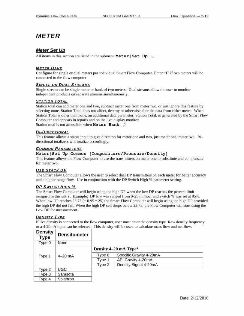
DENSITY TYPE
If live density is connected to the flow computer, user must enter the density type. Raw density frequency
or a 4-20mA input can be selected. This density will be used to calculate mass flow and net flow.
Density Type
Densitometer
Type 0 None
Type 1 4–20 mA
Density 4–20 mA Type*
Type 0 Specific Gravity 4-20mA
Type 1 API Gravity 4-20mA
Type 2 Density Signal 4-20mA
Type 2 UGC
Type 3 Sarasota
Type 4 Solartron
Dynamic Flow Computers SFC332GM Gas Manual Flow Equations — 2-13
Date: 2/12/2016
DENSITY 4-20MA TYPE*
Note that this type of input requires the user to choose a subtype, as indicated in the table above.
USE METER TEMPERATURE AS DENSITY TEMPERATURE
Meter | Set Up | Use Meter Temp as Dens.Temp#1
Meter | Set Up | Use Meter#2 Temp as Dens.Temp#2
To allow the meter temperature to calculate the effect of temperature on the densitometer. Make sure the
meter and density temperature are similar to avoid measurement errors.
Orifice Meter Data All items in this section are listed in the submenu Meter | Meter Data | ….
METER LOCATION
Up to 20 characters. This entry appears only in the report and serves no other function.
METER ID
Up to 8 characters. This function will serve as Meter Tag.
Pipe I .D. Mi l l imeters
Orif ice ID Mil l imeters
Pipe ID in millimeters is the measured inside pipe diameter to 4 decimals at reference conditions. Orifice
ID in millimeters is the measured diameter of the orifice at reference conditions.
DP Cutoff
The Smart Flow Computer suspends all calculations whenever the DP is less than this value. This function
is vital for suppressing extraneous data when the DP transmitter drifts around the zero mark under no-flow
conditions.
MASS FLOWRATE LOW /H IGH L IMIT
The high/low flow rate alarm is activated, when mass flow rate exceeds or is below the set limit. The alarm
will be documented with time, date, and totalizer.

Dynamic Flow Computers SFC332GM Gas Manual Flow Equations — 2-14
Date: 2/12/2016
DENSITY CALCULATION TYPE (0-9)
Calc. # Calculation Type Comments and Limitations
0 = NX19
1 = AGA8 Gross Method 1 Relative Density: 0.554–0.87
2 = AGA8 Gross Method 2 Relative Density: 0.554–0.87
3 = AGA8 Detail Method Relative Density: 0.07–1.52
4 = Steam Equations 260 T 2500 Deg.K
0 P 3000 MPa
5 = Ethylene NBS 1045 Up to 40 MPa (5000 PSIG)
6 = Parahydrogen (NBS 1048) Gas Form only
7 = Oxygen (NBS 1048) Gas Form only
8 = Nitrogen (NBS 1048) Gas Form only
9 = Argon (NBS 1048) Gas Form only
AGA 8 detail method can be used for gases other than natural gas, such as methane, carbon dioxide, ethane,
and hydrogen sulfide.
COMPOSITON ADDRESS
When G.C. and AGA8 detail method are selected, by entering the Unit ID in the “G.C. Comm Set UP”, floating point addresses for the gas composition in the G.C. must be entered and download(Press F3) to the Flow Computer. Press F2 to read current composition if the flow computer is communicating with the Gas Chromatograph.
GAS COMPOSIT ION
Enter the gas compositions for AGA8 detail method. The total percent of compositions should be 100.00 percent.
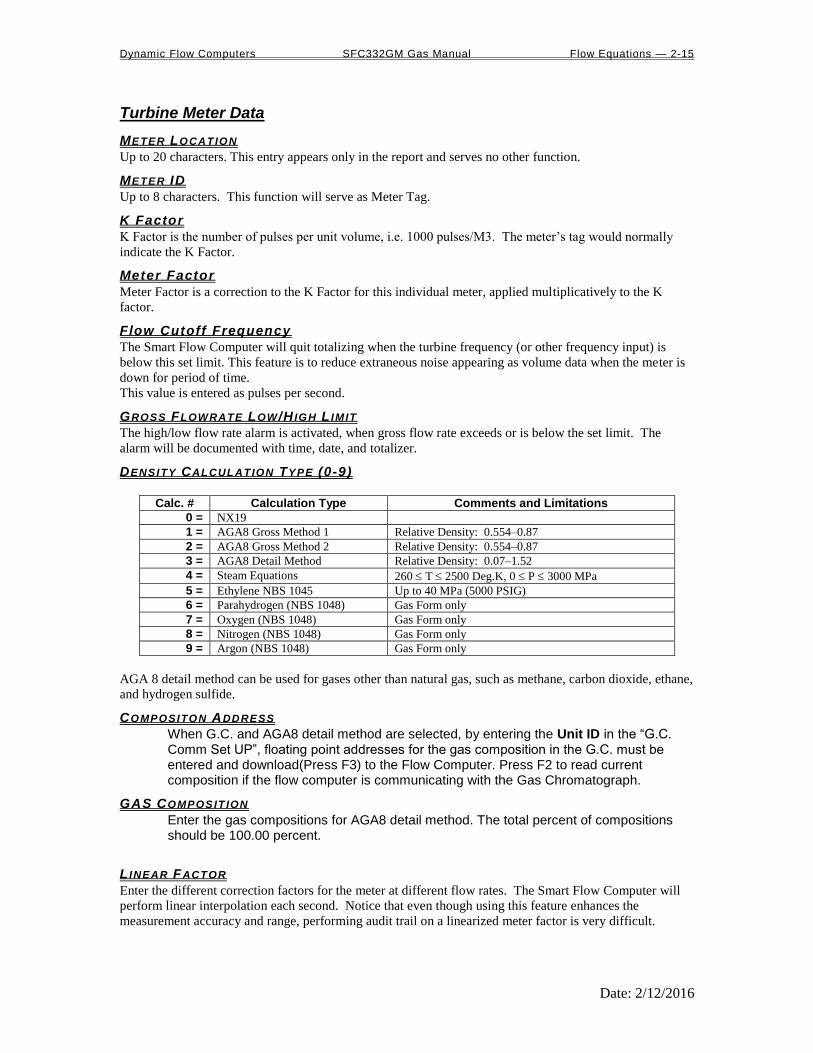
Dynamic Flow Computers SFC332GM Gas Manual Flow Equations — 2-15
Date: 2/12/2016
Turbine Meter Data
METER LOCATION
Up to 20 characters. This entry appears only in the report and serves no other function.
METER ID
Up to 8 characters. This function will serve as Meter Tag.
K Factor
K Factor is the number of pulses per unit volume, i.e. 1000 pulses/M3. The meter’s tag would normally
indicate the K Factor.
Meter Factor
Meter Factor is a correction to the K Factor for this individual meter, applied multiplicatively to the K
factor.
Flow Cutoff Frequency
The Smart Flow Computer will quit totalizing when the turbine frequency (or other frequency input) is
below this set limit. This feature is to reduce extraneous noise appearing as volume data when the meter is
down for period of time.
This value is entered as pulses per second.
GROSS FLOWRATE LOW /H IGH L IMIT
The high/low flow rate alarm is activated, when gross flow rate exceeds or is below the set limit. The
alarm will be documented with time, date, and totalizer.
DENSITY CALCULATION TYPE (0-9)
Calc. # Calculation Type Comments and Limitations
0 = NX19
1 = AGA8 Gross Method 1 Relative Density: 0.554–0.87
2 = AGA8 Gross Method 2 Relative Density: 0.554–0.87
3 = AGA8 Detail Method Relative Density: 0.07–1.52
4 = Steam Equations 260 T 2500 Deg.K, 0 P 3000 MPa
5 = Ethylene NBS 1045 Up to 40 MPa (5000 PSIG)
6 = Parahydrogen (NBS 1048) Gas Form only
7 = Oxygen (NBS 1048) Gas Form only
8 = Nitrogen (NBS 1048) Gas Form only
9 = Argon (NBS 1048) Gas Form only
AGA 8 detail method can be used for gases other than natural gas, such as methane, carbon dioxide, ethane,
and hydrogen sulfide.
COMPOSITON ADDRESS
When G.C. and AGA8 detail method are selected, by entering the Unit ID in the “G.C. Comm Set UP”, floating point addresses for the gas composition in the G.C. must be entered and download(Press F3) to the Flow Computer. Press F2 to read current composition if the flow computer is communicating with the Gas Chromatograph.
GAS COMPOSIT ION
Enter the gas compositions for AGA8 detail method. The total percent of compositions should be 100.00 percent.
L INEAR FACTOR
Enter the different correction factors for the meter at different flow rates. The Smart Flow Computer will
perform linear interpolation each second. Notice that even though using this feature enhances the
measurement accuracy and range, performing audit trail on a linearized meter factor is very difficult.

Dynamic Flow Computers SFC332GM Gas Manual Flow Equations — 2-16
Date: 2/12/2016
Other Parameters All parameters in this section are in the submenu Meter | Other Parameters | … unless otherwise
noted.
DAY START HOUR (0-23)
Day start hour is used for daily totalizer reset operation.
COMPANY NAME
Up to 20 characters. The company name appears in the reports.
FLOW RATE SELECTION
The flow rate will be based on daily basis, hourly, or minute.
FLOW RATE AVERAGED SECOND
The flow rate is averaged for 1-10 seconds to minimize fluctuating flow rate conditions. This number
averages the current flow rate by adding it to the previous seconds’ flow rate, and then displays an averaged
smoothed number. Only a low resolution pulse meter requires this function.
D ISABLE ALARMS
Use Disable Alarms to ignore alarms. When the alarm function is disabled alarms are not logged. Alarms
are also not logged if the DP is below the cut-off limit.
PRINT INTERVALS IN M INUTES (0-1440)
When the second port (RS-232) of the Smart Flow Computer is configured as printer port, a snapshot report
is generated every print interval (i.e., every five minutes, every hour, or every ten hours).
BASE TEMPERATURE DE G .C
The basis reference temperature for all corrections. Used, for example, when seller contracts to sell to buyer
at an agreed base temperature. Typically 60.0 °F in US units, 15 °C in Metric units.
BASE PRESSURE BAR
The basis reference pressure for all corrections. Used, for example, when seller contracts to sell to buyer at
an agreed base pressure. Typical values are 14.73 PSIA for US units, 1.01325 bar in Metric units.
ATMOSPHERIC PRESSURE BAR
This pressure is the local pressure or contracted atmospheric pressure to be used. Typical value is 1.01325
BAR.
RUN SWITCHING
Run switching is used to switch from tube one to tube two, when flow rate reaches certain limits. The
Smart Flow Computer has one active output that can be dedicated to this function. The time delay allows
for some delay in switching.
Note: if Run Switching is being used, then the meter should be configured for a single stream (see Set Up under Meter).
RUN SWITCH H IGH SET POINT
When this flow rate value is exceeded and after the delay timer expires, the switch output will activate.
This output normally opens meter run two. The Smart Flow Computer provides open collector type output
that requires external power.
RUN SWITCH LOW SET POINT
When the flow rate drops below this value and stays below it until the delay timer expires, the output
switch will be turned off to shut meter two.

Dynamic Flow Computers SFC332GM Gas Manual Flow Equations — 2-17
Date: 2/12/2016
PULSE OUTPUT AND PULSE OUTPUT W IDTH
Pulse Output is used to activate a sampler or external totalizer. The number selected will be pulses per unit
volume or per unit mass. If 0.1 pulse is selected, the one pulse will be given every 10 unit volumes has
passed through the meter.
Pulse Output Width is the duration, in milliseconds, of one complete pulse cycle (where each cycle is the
pulse plus a wait period, in a 50/50 ratio). For example: if POW = 500 msec, the Smart Flow Computer at
most can produce one pulse each second regardless of the pulse per unit volume selected (500 msec pulse +
500 msec wait). If POW = 10 msec the Smart Flow Computer can produce up to 50 pulses per second.
The Smart Flow Computer’s maximum pulse output is 125 pulses/sec. The Pulse Output in combination
with the Pulse Output Width should be set appropriately.
SELECT UNIT 0=M3, 1=MCF
When MCF is selected, gross, net, mass energy volumes, and totalizers will be converted to US unit.
Calc . Parameters All parameters in this section are in the submenu Meter | Calc. Parameters | … unless otherwise
noted.
ORIFICE CALCULATION TYPE (0=ISO5167,1=API.14.3)
Select the desired calculations mode. API 14.3 is the latest orifice calculations introduced in 1994.
ISO 5167 is another calculation option.
METER CALCULATION TYPE (0=ORIFICE , 1=TURBINE )
Enter ‘0’ to use orifice meter, or ‘1’ if AGA7 turbine meter is used.
DENSITY OF DRY A IR
This represents are the number of grams per mole. .
RELATIVE DENSITY
The real gas relative density is used in the calculations of the compressibility factor, flowing and reference
densities.
Y FACTOR (0=NONE ,1=UPSTREAM ,2=DOWNSTREAM )
Y factor is the expansion factor through the orifice. The user must enter the position of the pressure and
temperature sensors. Select y=1 if the sensors are installed upstream of the orifice plate. Select y=2 if the
sensors are down stream of the orifice plate.

Dynamic Flow Computers SFC332GM Gas Manual Flow Equations — 2-18
Date: 2/12/2016
SELECT 0=FLANGE TAP , 1=P IPE TAP
Tap position is where the differential transmitter is fitted. Select 0 = flange fitted or 1 = pipe fitted.
ISENTROPIC EXPONENT (SPECIF IC HEAT )
Ratio of specific heat is a constant associated with each product. Even though it varies slightly with
temperature and pressure, in most cases it is assumed as a constant.
V ISCOSITY IN CENTIPOISE
Viscosity is entered in centipoise even though viscosity will shift with temperature and pressure, the effect
on the calculations is negligent. Therefore using a single value is appropriate in most cases.
REFERENCE TEMPERATURE OF ORIF ICE
Reference temperature of orifice is the temperature at which the orifice bore internal diameter was
measured. Commonly 68 Deg.F, or 20 Deg.C is used.
ORIFICE THERMAL EXPANSION COEFF . E-6
Orifice thermal expansion is the linear expansion coefficient of orifice material.
Type 304 and 316 Stainless 9.25 E-6
Monel 7.95 E-6
Carton Steel 6.20 E-6
REFERENCE TEMPERATURE OF P IPE
Reference temperature of pipe is the temperature at which the pipe bore internal diameter was measured.
Commonly 68 Deg.F or 20 Deg.C is used.
P IPE THERMAL EXPANSION COEFF . E-6
Pipe thermal expansion is the linear expansion coefficient of pipe material.
Type 304 and 316 Stainless 9.25 E-6
Monel 7.95 E-6
Carbon Steel 6.20 E-6
D ISTANCE OF UPSTREAM TAPPING
Distance of upstream tapping from the upstream face of the plate
D ISTANCE OF DOWNSTREAM TAPPING
Distance of upstream tapping from the face of the orifice plate

Dynamic Flow Computers SFC332GM Gas Manual Flow Equations — 2-19
Date: 2/12/2016
Date and Time Meter | Date/Time
The PC software will show the current date and time from the PC. Press <F3> to download that date and
time to the flow computer. Press <F2> to upload the date and time from the flow computer.
Parameter Overrides
Temperature Override Meter | Temperature Override
Pressure Override Meter | Pressure Override
Heating Value Override Meter | Heating Value Override
Base Density Override Meter | Base Dens Override
FPV Override Meter | Fpv Override
An override value is entered when no live parameter value is available, or when a different value from live
value should be used. In the diagnostic screen, the fail code will appear as 9. Zero in the data entry
indicates use live value.
BTU override is used in the AGA8 calculation GROSS METHOD 1. In addition the heating value totalizer
requires the heating value; without a BTU override value entered, the Energy Flowrate will always equal
zero. Enter this number in MJ/M3.
Base Density override is used to override the calculated base density and affects the net calculations only.
For products other than natural gas, you must enter base density override for net calculations.
Fpv override: used to enter a value to override the NX19 supercompressibility factor.
Security Code Meter | Security Code
Several levels of security codes have been selected to fit different levels of responsibility. Up to six
alphanumeric code can be used for each entry. If the security code is not used, then there will not be any
security code prompt in the menu.
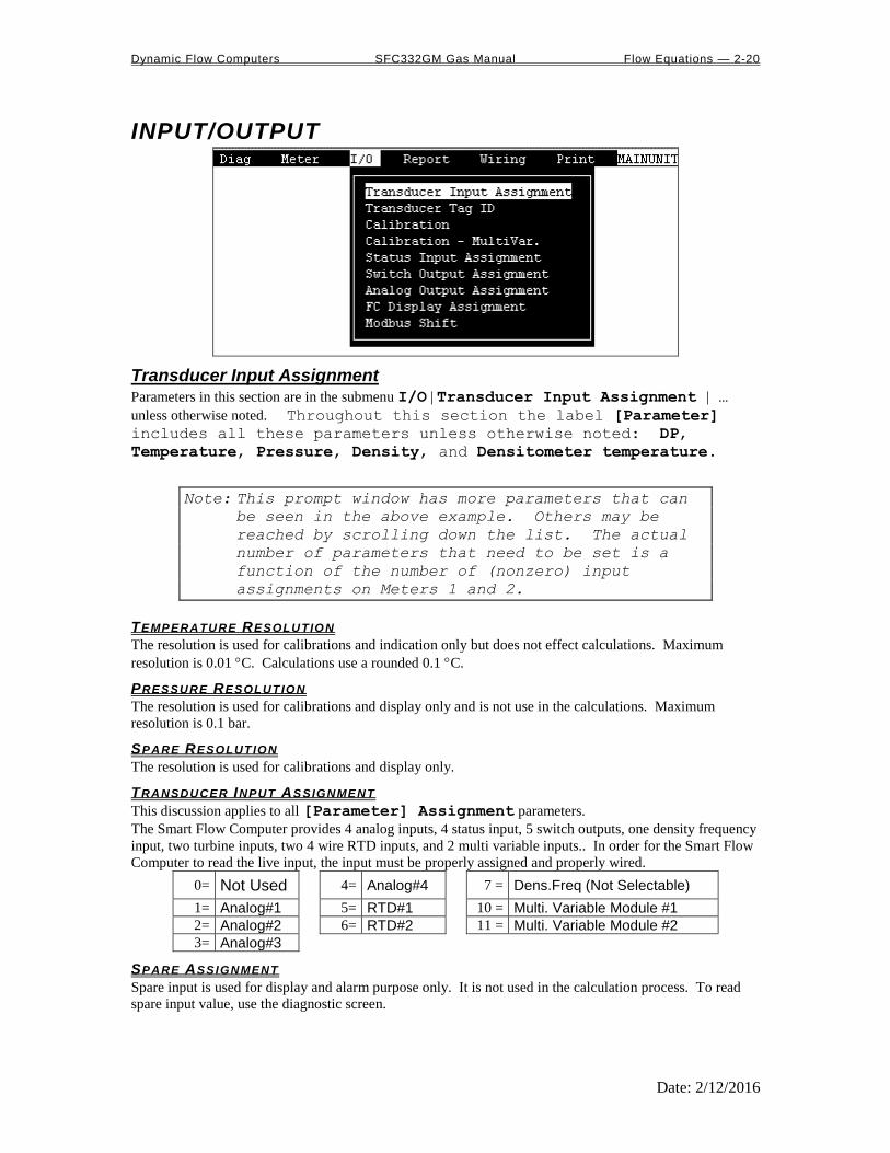
Dynamic Flow Computers SFC332GM Gas Manual Flow Equations — 2-20
Date: 2/12/2016
INPUT/OUTPUT
Transducer Input Assignment Parameters in this section are in the submenu I/O | Transducer Input Assignment | …
unless otherwise noted. Throughout this section the label [Parameter]
includes all these parameters unless otherwise noted: DP,
Temperature, Pressure, Density, and Densitometer temperature.
Note: This prompt window has more parameters that can
be seen in the above example. Others may be
reached by scrolling down the list. The actual
number of parameters that need to be set is a
function of the number of (nonzero) input
assignments on Meters 1 and 2.
TEMPERATURE RESOLUTION
The resolution is used for calibrations and indication only but does not effect calculations. Maximum
resolution is 0.01 C. Calculations use a rounded 0.1 C.
PRESSURE RESOLUTION
The resolution is used for calibrations and display only and is not use in the calculations. Maximum
resolution is 0.1 bar.
SPARE RESOLUTION
The resolution is used for calibrations and display only.
TRANSDUCER INPUT ASSIGNMENT
This discussion applies to all [Parameter] Assignment parameters.
The Smart Flow Computer provides 4 analog inputs, 4 status input, 5 switch outputs, one density frequency
input, two turbine inputs, two 4 wire RTD inputs, and 2 multi variable inputs.. In order for the Smart Flow
Computer to read the live input, the input must be properly assigned and properly wired.
0= Not Used 4= Analog#4 7 = Dens.Freq (Not Selectable)
1= Analog#1 5= RTD#1 10 = Multi. Variable Module #1
2= Analog#2 6= RTD#2 11 = Multi. Variable Module #2
3= Analog#3
SPARE ASSIGNMENT
Spare input is used for display and alarm purpose only. It is not used in the calculation process. To read
spare input value, use the diagnostic screen.
Dynamic Flow Computers SFC332GM Gas Manual Flow Equations — 2-21
Date: 2/12/2016
4MA
Enter the 4mA value for the transducer.
Note that this value cannot be edited if [Parameter] Assignment = 0. Therefore to set the
parameter Meter#1 Temperature @4mA the Temperature Assignment parameter
cannot equal zero.
Note that any [Parameter] can potentially have a @4mA setting.
20MA
Enter the 20mA value for the transducer.
Note that this value cannot be edited if [Parameter] Assignment = 0. Therefore to set the
parameter Meter#1 Temperature @20mA the Temperature Assignment parameter
cannot equal zero.
Note that any [Parameter] can potentially have a @20mA setting.
LOW /H I L IMIT
Enter the low and high limits. When live value exceeds high limit or less than low limit, a alarm log will be
generated.
Note that this value cannot be edited if [Parameter] Assignment = 0. Therefore to set the
parameter Meter#1 Temperature Low Limit the Temperature Assignment
parameter cannot equal zero.
MAINTENANCE VALUE
The value will be used when the transmitter fails, or while calibrating. Set fail code to 1 while calibrating.
Note that this value cannot be edited if [Parameter] Assignment = 0. Therefore to set the
parameter Meter#1 Temperature Maintenance the Temperature Assignment
parameter cannot equal zero.
Note that any [Parameter] can potentially have a Maintenance setting.
FAIL CODE
Fail Code 0: always use the live value even if the transmitter failed.
Fail Code 1: always use the maintenance value
Fail Code 2: use maintenance value if transmitter failed. i.e. 4-20mA is above 21.75 or
below 3.25)
Note that this value cannot be edited if [Parameter] Assignment = 0. Therefore to set the
parameter Meter#1 Temperature Maintenance the Temperature Assignment
parameter cannot equal zero.
Note that any [Parameter] can potentially have a Maintenance setting.
DENSITY PERIOD LOW /H IGH L IMITS
Density Period is the time period in microseconds. The densitometer fails if the density period exceeds the
density period low or high limits. If the densitometer fails and density fail code is set to 2, the maintenance
value will be used.
Transducer Tag ID I/O | Transducer Tag ID
Up to 8 alphanumeric ID number. The transmitters are referred to according to the TAG ID. All alarms
are labeled according to TAG ID.
Calibration See details in chapter 1.
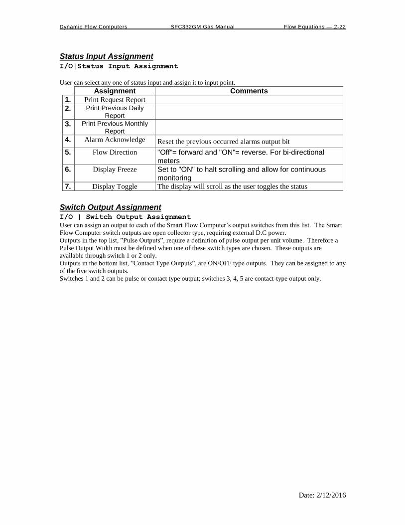
Dynamic Flow Computers SFC332GM Gas Manual Flow Equations — 2-22
Date: 2/12/2016
Status Input Assignment I/O | Status Input Assignment
User can select any one of status input and assign it to input point.
Assignment Comments
1. Print Request Report
2. Print Previous Daily Report
3. Print Previous Monthly Report
4. Alarm Acknowledge Reset the previous occurred alarms output bit
5. Flow Direction "Off"= forward and "ON"= reverse. For bi-directional meters
6. Display Freeze Set to "ON" to halt scrolling and allow for continuous monitoring
7. Display Toggle The display will scroll as the user toggles the status
Switch Output Assignment I/O | Switch Output Assignment
User can assign an output to each of the Smart Flow Computer’s output switches from this list. The Smart
Flow Computer switch outputs are open collector type, requiring external D.C power.
Outputs in the top list, ”Pulse Outputs”, require a definition of pulse output per unit volume. Therefore a
Pulse Output Width must be defined when one of these switch types are chosen. These outputs are
available through switch 1 or 2 only.
Outputs in the bottom list, ”Contact Type Outputs”, are ON/OFF type outputs. They can be assigned to any
of the five switch outputs.
Switches 1 and 2 can be pulse or contact type output; switches 3, 4, 5 are contact-type output only.

Dynamic Flow Computers SFC332GM Gas Manual Flow Equations — 2-23
Date: 2/12/2016
ASSIGNMENTS - PULSE OUTPUTS
Meter 1 Meter 2 Station
Gross 1 5 9
Net 2 6 10
Mass 3 7 11
Energy 4 8 12
ASSIGNMENTS - CONTACT TYPE OUTPUTS
Meter1 Meter2 Meter-Independent Parameters Temperature Low 26 36 Day Ended 19
Temperature High 27 37 Dens. Period Low 46
Pressure Low 28 38 Dens. Period High 47
Pressure High 29 39 AGA8 Out of Range 48
Density Low 30 40 Steam Out of Range 49
Density High 31 41 Ethylene Out of Range 50
Dens.Temp Low 32 42 Active Alarms 51
Dens.Temp High 33 43 Occurred Alarms 52
DP Low 34 44 Status Input #1 57
DP High 35 45 Run Switch 58
Meter Down 20 23 Print in Progress 59
Flow Rate Low 21 24
Flow Rate High 22 25
Direction–Forward 53 55
Direction–Reverse 54 56
Note: Assignments 13–18 are not used.
Examples:
10= Station Net Flowrate (pulse output)
48= AGA8 out of Range
53= Meter 1 Direction Forward

Dynamic Flow Computers SFC332GM Gas Manual Flow Equations — 2-24
Date: 2/12/2016
Analog Output Assignment 4-20mA selection must be proportional and within the range of the selected parameter. The 4-20mA signal
is 12 bits.
ASSIGNMENTS :
Meter 1 Meter 2 Station
Gross Flow Rate 1 5 9
Net Flow Rate 2 6 10
Mass Flow Rate 3 7 11
Energy Flow Rate 4 8 12
Meter 1
Meter2 Meter-Independent Parameters
DP 13 21 Spare #1 33
Temperature 14 22 Spare #2 34
Pressure 15 23 Remote Control* 35
Density 16 24
Examples:
9 = Station Gross Flowrate
30 = Meter 1 Specific Gravity
25 = Meter 2 Density Temperature
Density Temp 17 25
Dens.b 18 26
DP LOW 19 27
DP HIGH 20 28
Specific Gravity 30 32
Note: Assignments 29 and 31 are not used.
*Note: Remote control output can be controlled through the Modbus communication link.
Note: Dens.b = Base Density
DP = Differential Pressure

Dynamic Flow Computers SFC332GM Gas Manual Flow Equations — 2-25
Date: 2/12/2016
Smart Flow Computer Display Assignment Display assignment select up to 17 assignments. The Smart Flow Computer will scroll through them at the
assigned delay time. Active alarm will automatically prompt on the screen if alarm conditions exists (see
Assignment #51). To read active alarms, use the diagnostic screen.
ASSIGNMENT
Meter 1 Meter 2 Station
Gro
ss
Net
Mass
En
erg
y
Gro
ss
Net
Mass
En
erg
y
Gro
ss
Net
Mass
En
erg
y
Flow Rate 1 2 3 4 5 6 7 8 9 10 11 12
Forward Total 13 14 15 16 17 18 19 20 21 22 23 24
Reverse Total 25 26 27 28 29 30 31 32 33 34 35 36
Meter 1 Meter2 Meter-Independent Parameters
DP 37 52 Density Frequency 48
Temperature 38 53 Spare #1 / #2 49
Pressure 39 54 Time / Date 50
Density 40 55 Alarm 51
Density Temp. 41 56
DP Low / High 42 57
Specific Gravity 43 58
Density b 44 59
Density Period 45 60
Uncorr.Density 46 61
Product 47 62
Examples:
26= Meter 1 Net Reverse Total Flowrate
39= Meter 1 Pressure
48= Density Frequency

Dynamic Flow Computers SFC332GM Gas Manual Flow Equations — 2-26
Date: 2/12/2016
Modbus Shift Reassigns Modbus address registers on the Smart Flow Computer to predefined Modbus registers for easy
polling and convenience. Use Modbus Shift to collect values in scattered Modbus registers into a
consecutive order. The Smart Flow Computer will repeat the assigned variables into the selected locations.
Note: some Modbus registers are 2 byte/16 bit, and some are 4 byte/32 bit. Register size incompatibility
could cause rejection to certain address assignments. Refer to the Modbus Address Table Registers in
Chapter 4.
Example: you want to read the current status of switches #1 and #2 (addresses 2617 and 2618) and the
Forward and Reverse Daily Gross Total for Meter #1 ( addresses 3173 and 3189). Make assignments such
as:
3082=2617 (2 bytes)
3083=2618 (2 bytes)
3819=3173 (4 bytes)
3821=3189 (4 bytes)

Dynamic Flow Computers SFC332GM Gas Manual Flow Equations — 2-27
Date: 2/12/2016
REPORTS
Current Data - Snapshot Totalizer Updates This report consists of two sections. The upper section is primarily the non changing parameters, the
bottom section is the dynamic. Press any key to move from one section of the report to the other. Press
<F8> to freeze, then press <F5> to print, or enter the file name and press <F6> to capture the snapshot
data.
Previous Hourly Data Up to 840 previous hourly data are stored in the Smart Flow Computer. Enter starting hour and date, the
Smart Flow Computer will go backward from that selected time and date. Current hour cannot be selected.
Press <F4> to display, then press <F5> to print, or enter the file name and press <F6> to capture the
"Previous Hourly Report".
Previous Daily Data Up to 3 previous daily reports can be retrieved. Current day data cannot be retrieved. Press <F4> to
display, then press <F5> to print, or enter the file name and press <F6> to capture the "Previous Daily
Report."
Previous Monthly Data Up to 12 previous month data are stored in the Smart Flow Computer. Select number of previous month
data to display, print, or capture. Current month data cannot be retrieved. . Press <F4> to display, then
press <F5> to print, or enter the file name and press <F6> to capture the "Previous Monthly Report."
Previous Alarm Data Up to 100 previous alarm data can be retrieved. Starting from the most recent to the oldest. Press <F4> to
display, then press <F5> to print, or enter the file name and press <F6> to capture the "Previous Alarm
Report".
Audit Trail Report The audit trail report shows configuration parameters that has changed which could influence the calculated
numbers. The Smart Flow Computer provides up to 100 event logs. One purpose for audit trail is to back
track calculation errors that result from mistakes by the operator of the flow computer operator. . Press
<F4> to display, then press <F5> to print, or enter the file name and press <F6> to capture the "Audit Trail
Report".
Build User Report One screen can be built or edited with this menu. Any text can be used. Modbus register must follow the
"^" sign in order for the program to retrieve the address location.
View User Report To monitor the Build User Report. User reports can be printed through the PC parallel port–see
Print | Files.

Dynamic Flow Computers SFC332GM Gas Manual Flow Equations — 2-28
Date: 2/12/2016
Formatted Ticket Report The Smart Flow Computer allows the user to make personal ticket report. This ticket report is just for
display and printing purposes. To make this report, user must use "Last Daily Data Area" in the Modbus
registers (3431-3703).
Example: DYNAMIC FLUID BATCH REPORT
METER 1 PRODUCT SELECTION ^3437
METER 1 MASS TOTAL ^3449
Results - The report will look as follows: DYNAMIC FLUID BATCH REPORT
METER 1 PRODUCT SELECTION 3
METER 1 MASS TOTAL 34563.2
Ticket Report Select 0=Standard Report, 1=Format Ticket Report
Standard is the default report format that is programmed in the Smart Flow Computer. Format is according
to the formatted daily report.
Capture File Name - capture that file under certain name.
Auto Data Retrieval This function is made to replace printers and use PC to poll the configured units on time basis (Hourly or
Daily). All parameters polled will be stored in the configured file name. Each unit ID will have individual
file name. The PC or laptop must be on at the time it has to get the data, and the user must activate that
function by pressing <F3> and leaving the PC on. The data format can be either standard or user defined
format. This function is to eliminate the need for paper and make the process more environmentally
friendly. Echo to the local printer can be enabled where reports will be stored on hard drive and printed to
the printer on the parallel port.

Dynamic Flow Computers SFC332GM Gas Manual Flow Equations — 2-29
Date: 2/12/2016
WIRING See the wiring diagrams in the Wiring section of Chapter 1, “Quick Start”.
To print wiring diagram, you have to run your Smart Flow Computer software in Windows, then copy the
entire screen onto the Clipboard.
1. Type win and press <ENTER> (run window).
2. Point to MDOS Prompt and click.
3. Type "A:", and press <ENTER>.
4. Type "SFC332” and press <ENTER>.
5. Use arrow keys to move to Wiring and then to the desired diagram.
6. Press <ALT>+ <ENTER>, then press <ALT> +SPACEBAR to open Control menu for
the application.
7. From the Control menu, choose Edit, and then choose Mark. A flashing rectangular
cursor appears at the upper left corner of the window.
8. Move the cursor to the first character you want to select.
9. Mark the information you want to copy, and press <ENTER> to transfer the selected
information onto the Clipboard.
10. Start an application (Microsoft Word), Place the insertion point at the place you want
the information from the Clipboard to appear. From the application's Edit menu,
choose Paste.

Dynamic Flow Computers SFC332GM Gas Manual Flow Equations — 2-30
Date: 2/12/2016
Print "Help" File Turn on parallel printer, point the cursor to Print | Help, press <ENTER>,
and then press <F5> to print "Help" file. Note that this prints all on-line helps;
this print function does not print context-specific help information.
Print Modbus Registers Turn on parallel printer, point the cursor to Print | Modbus Reg, press <ENTER>, and then press
<F5> to print Modbus registers. Note that this print request generates basically Chapter 4 of this manual,
Modbus Data. It does not print the contents of the Modbus registers.
Print Schematic Turn on parallel printer, point the cursor to Print | Schematic, press <ENTER>, and then press
<F5> to print the schematic of the Back Panel Terminal Board (only). Terminals and jumpers are indicated
on this schematic.
Print Calibration Data
Calibration data are programmed parameters in the data file. To print, turn on parallel printer, point the
cursor to Print | Calib. Data, press <ENTER>, and then press <F5>. This printing function’s
name is slightly misleading: though the calibration data is printed, in actuality the configuration file
currently resident in memory is printed in its entirety.
Print Files The user can print the files that were captured by a Report command. Turn on the parallel printer, move
the cursor to the desired file, and then press <ENTER>.

Dynamic Flow Computers SFC332GM Gas Manual Flow Equations — 3-1
Date: 2/12/2016
CHAPTER 3: Flow Equations
Common Terms The following terms are used throughout this chapter.
Term Definition Units Examples
q Flowrate: volume or mass displaced per unit
time See equations qmass , qenergy
T Temperature F unless noted
DP Differential Pressure across measuring device Inches H2O column
d Orifice Diameter Inches d , dr , dm
D Pipe Diameter Inches D , Dr , Dm
diameter Pipe
diameter Orifice
D
d Dimensionalless ratio , r
Density (usually of the fluid) Lb/ft3 flowing , m
Viscosity centipoise
HN Heating Value
Y Expansion factor Dimensionalless
Subscripts: Conventions Used
This Subscript Means Examples r At reference conditions Tr,p = reference temperature of the pipe
O (letter o) Refers to the orifice Tr,O = reference temperature of the orifice
P Refers to the pipe
flowing At flow conditions flowing = density at flow conditions
cal Calibration conditions Tcal , Pcal
m At measured conditions Dm = pipe diameter at measured temp.

Dynamic Flow Computers SFC332GM Gas Manual Flow Equations — 3-2
Date: 2/12/2016
ISO5167
Mass Flow Rate (TON/HR)
3.14159 x Alpha x FA x Exp. x 3600.0 x d2 x SQRT(2000 x DP x Density) / 1000000
4
Net Flow Rate (KM3/HR)
Mass Flow Rate / Base Density
Gross Flow Rate (KM3/HR)
Mass Flow Rate / Flowing Density
Energy Flow Rate (GJ/HR)
Net Flow Rate x Heating Value / 1000.0
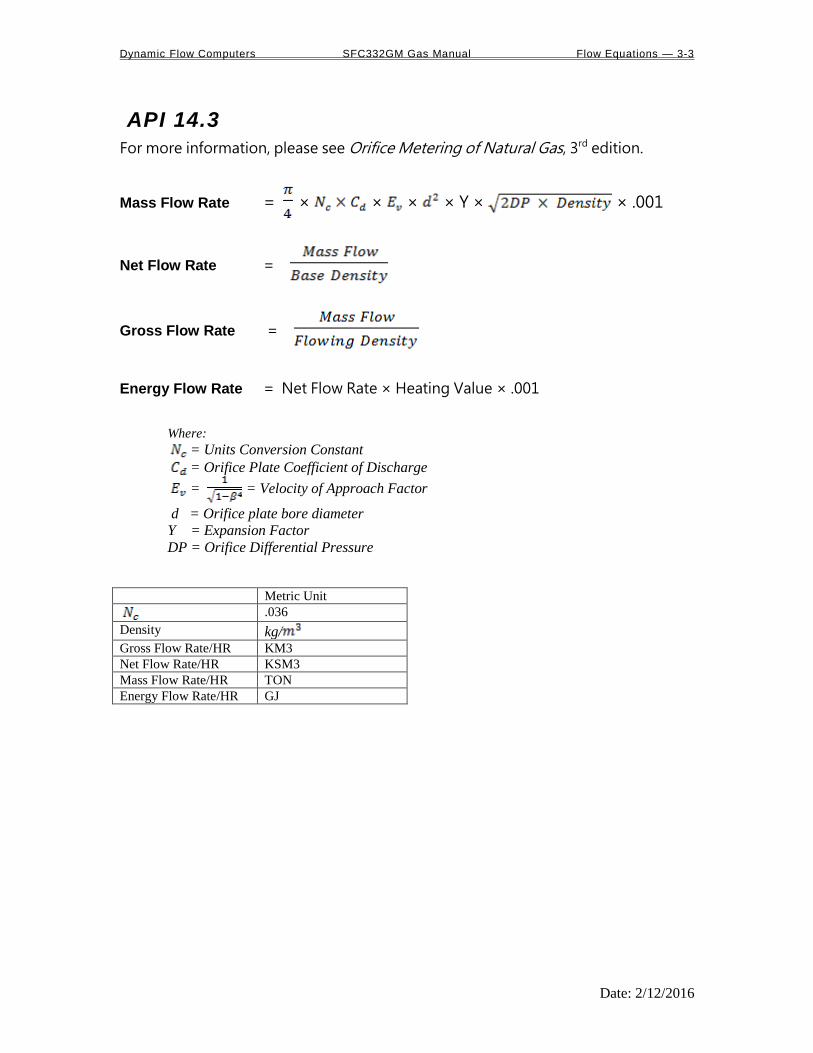
Dynamic Flow Computers SFC332GM Gas Manual Flow Equations — 3-3
Date: 2/12/2016
API 14.3
For more information, please see Orifice Metering of Natural Gas, 3rd edition.
Mass Flow Rate = × × × × Y × × .001
Net Flow Rate =
Gross Flow Rate =
Energy Flow Rate = Net Flow Rate × Heating Value × .001
Where:
= Units Conversion Constant
= Orifice Plate Coefficient of Discharge
= = Velocity of Approach Factor
d = Orifice plate bore diameter
Y = Expansion Factor
DP = Orifice Differential Pressure
Metric Unit
.036
Density kg/
Gross Flow Rate/HR KM3
Net Flow Rate/HR KSM3
Mass Flow Rate/HR TON
Energy Flow Rate/HR GJ

Dynamic Flow Computers SFC332GM Gas Manual Flow Equations — 3-4
Date: 2/12/2016
AGA 7
Gross Flowrate (KM3/HR)
= Total (Pulses/Second) x Meter Factor x Linear Factor x 3.6 Nominal K Factor
Net Flowrate (KSM3/HR)
= Gross Flow Rate x Flowing Density / Reference Density
Mass Flowrate (TON/HR)
= Gross Flow Rate x Flowing Density
Energy Flowrate (GJ/HR)
= Mass Flow Rate x Heating Value x 0.001 Reference Density

Dynamic Flow Computers SFC332GM Gas Manual Flow Equations — 3-5
Date: 2/12/2016
DENSITY EQUATIONS
Sarasota Density KG/M3 Sarasota density is calculated using the frequency signal produced by a Sarasota densitometer, and applying
temperature and pressure corrections as shown below.
Corrected Density = DCF x (2 x D0 x (t-T0p)/T0p x ( 1 + K x (t-T0p)/(2 x T0p) )
Where T0p = Tcoef x (T - Tcal) + Pcoef x (P - Pcal) + T0
DCF = Density Correction Factor
D0 = A Calibration constant, mass/volume,KG/M3
t = The densitometer oscillation period in microseconds. T = Flowing temperature Deg.C T0 = A calibration constant in microseconds
Tcoef = Temperature coefficient in microseconds/Deg.C P = Flowing pressure in bar Pcoef = Pressure coefficient in microseconds/bar Pcal = Calibration pressure in bar

Dynamic Flow Computers SFC332GM Gas Manual Flow Equations — 3-6
Date: 2/12/2016
UGC Density KG/M3 UGC density is calculated using the frequency signal produced by a UGC densitometer, and applying
temperature and pressure corrections as shown below
d = K0 + (K1 x t) + (K2 x t2)
Corrected Density = DCF x (P x (K x (P0 + d) x 10-6 +Kt x (T-Tcal) + d)
Where : K0, K1, K2 = Calibration Constants
t = The densitometer oscillation period in microseconds. DCF = Density Correction Factor P = Flowing pressure in bar K = Pressure Constant P0 = Pressure Offset
Kt = Temperature Coefficient
T = Flowing temperature Deg.C Tcal = Temperature coefficient in microseconds/Deg.C

Dynamic Flow Computers SFC332GM Gas Manual Flow Equations — 3-7
Date: 2/12/2016
Solartron Density GM/CC Solartron density is calculated using the frequency signal produced by a Solartron densitometer, and
applying temperature and pressure corrections as shown below.
Density at 20 Deg.C and 0 BAR
D=K0 + K1 x t + K2 x t2
Where t = Densitometer Oscillation Period in microseconds K0,K1,K2 = Calibration Constants Supplied by Solartron
Temperature Corrected Density DT = D x (1+K18 x (T-20) ) + K19 x (T-20)
Where T = Temperature Deg.C
Temperature and Pressure Corrected Density DP = DL x (1 + K20 x P) + K21 x P
Where P = Pressure in bar K20 = K20A + K20B x P
K21 = K21A + K21B x P
K20A, K20B, K21A, K21B = Calibration Constants Supplied by Solarton
Additional Equation for Velocity of Sound Effects The following equation can provide more accurate measurement for LPG products in the range of
300.0 to 550.0 KG/M3
Dvos = DP + Kr (DP - Kj)3 Products outside of this range should enter 0.0 for Kr.
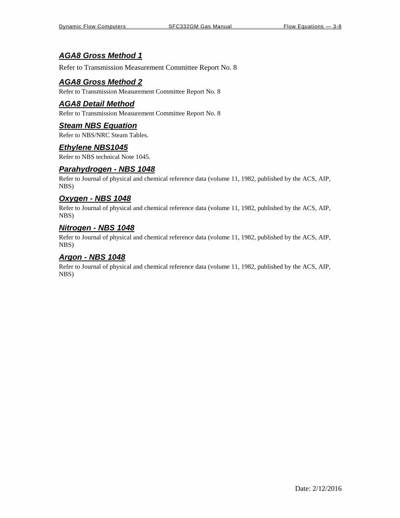
Dynamic Flow Computers SFC332GM Gas Manual Flow Equations — 3-8
Date: 2/12/2016
AGA8 Gross Method 1
Refer to Transmission Measurement Committee Report No. 8
AGA8 Gross Method 2 Refer to Transmission Measurement Committee Report No. 8
AGA8 Detail Method Refer to Transmission Measurement Committee Report No. 8
Steam NBS Equation Refer to NBS/NRC Steam Tables.
Ethylene NBS1045 Refer to NBS technical Note 1045.
Parahydrogen - NBS 1048 Refer to Journal of physical and chemical reference data (volume 11, 1982, published by the ACS, AIP,
NBS)
Oxygen - NBS 1048 Refer to Journal of physical and chemical reference data (volume 11, 1982, published by the ACS, AIP,
NBS)
Nitrogen - NBS 1048 Refer to Journal of physical and chemical reference data (volume 11, 1982, published by the ACS, AIP,
NBS)
Argon - NBS 1048 Refer to Journal of physical and chemical reference data (volume 11, 1982, published by the ACS, AIP,
NBS)

Dynamic Flow Computers SFC332GM Gas Manual Modbus Data — 4-1
Date: 2/12/2016
CHAPTER 4: MODBUS DATA
MODBUS PROTOCOL
TRANSMISSION MODE
ASCII RTU
DATA BITS 7 8
START BITS 1 1
PARITY EVEN, ODD NONE
STOP BITS 1 1
ERROR CHECKING LRC CRC
BAUD RATE 1200-9600 1200-9600
ASCII FRAMING Framing is accomplished by using colon (:) character indicating the beginning of frame and carriage (CR),
line feed (LF) for the end of frame
ASCII MESSAGE FORMAT ADDRESS FUNCTION DATA ERR\CHECK
: 2 CHAR 2 CHAR Nx2 CHAR 2 CHAR CR LF
8 BITS 16 BITS 16 BITS Nx16 BITS 16 BITS 8 BITS 8 BITS
RTU FRAMING Frame synchronization is done by time basis only. The Smart Flow Computer allows 3.5 characters time
without new characters coming in before proceeding to process the message and resetting the buffer.
RTU MESSAGE FORMAT ADDRESS FUNCTION DATA CRC
8 BITS 8 BITS Nx8 BITS 16 BITS

Dynamic Flow Computers SFC332GM Gas Manual Modbus Data — 4-2
Date: 2/12/2016
FUNCTION CODE To inform the slave device of what function to perform
FUNCTION CODE
ACTION
01
03 Read Strings or Multiple 16 Bits
16 Write Strings or Multiple 16 Bits
ERROR CHECK
LRC MODE The LRC check is transmitted as two ASCII hexadecimal characters. First, the message has to be stripped
of the: LF, CR, and then converted the HEX ASCII to Binary. Add the Binary bits and then two's
complement the result.
CRC MODE The entire message is considered in the CRC mode. Most significant bit is transmitted first. The message is
pre-multiplied by 16. The integer quotient digits are ignored and the 16-bit remainder is appended to the
message as the two CRC check bytes. The resulting message including the CRC, when divided by the
same polynomial (X16+X15+X2+1) at the receiver, which will give zero remainder if no error, has
occurred.
EXCEPTION RESPONSE Exception response comes from the slave if it finds errors in communication. The slave responds to the
master echoing the slave address, function code (with high bit set), exception code and error check. To
indicate that the response is notification of an error, the high order bit of the function code is set to 1.
EXCEPTION CODE DESCRIPTION
01 Illegal Function
02 Illegal Data Address
03 Illegal Data Value
BROADCAST COMMAND All units listen to Unit ID Zero, and no one will respond when the write function is broadcasted.

Dynamic Flow Computers SFC332GM Gas Manual Modbus Data — 4-3
Date: 2/12/2016
MODBUS EXAMPLES
FUNCTION CODE 03 (Read Single or Multiple Register Points) RTU MODE - Read Address 3076
ADDR FUNC CODE
STARTING POINT # OF POINTS CRC CHECK
HI LO HI LO
01 03 0C 04 00 01 C6 9B
Response
ADDR FUNC CODE
BYTE COUNTS
DATA CRC CHECK
HI LO
01 03 02 00 01 79 84
Write Address 3076
ADDR FUNC CODE
START POINT
# OF POINTS
BYTE COUNTS
DATA CRC CHECK
HI LO HI LO HI LO
01 10 0C 04 00 01 02 00 01 AA 14
Response
ADDR FUNC CODE
START ADDR
# OF POINTS
CRC CHECK
C 10 0C 04 01 43 58
ASCII MODE - Read Address 3076
ADDR FUNC CODE
STARTING POINT # OF POINTS LRC CHECK
HI LO HI LO
: 30 31 30 33 30 43 30 43 30 30 30 31 45 42 CR LF
Response
ADDR FUNC CODE
BYTE COUNT
DATA LRC CHECK
HI LO
: 30 31 30 33 30 32 30 30 30 31 46 39 CR LF

Dynamic Flow Computers SFC332GM Gas Manual Modbus Data – 4-4
Modbus Address Table – 16 Bits ADDRESS DESCRIPTION DECIMAL READ/WRITE
Date: 2/12/2016
2534 Smart FC Display Delay 0 Inferred Read/Write 2535 Smart FC Assignment #1 0 Inferred Read/Write 2536 Smart FC Assignment #2 0 Inferred Read/Write 2537 Smart FC Assignment #3 0 Inferred Read/Write 2538 Smart FC Assignment #4 0 Inferred Read/Write 2539 Smart FC Assignment #5 0 Inferred Read/Write 2540 Smart FC Assignment #6 0 Inferred Read/Write 2541 Smart FC Assignment #7 0 Inferred Read/Write 2542 Smart FC Assignment #8 0 Inferred Read/Write 2543 Smart FC Assignment #9 0 Inferred Read/Write 2544 Smart FC Assignment #10 0 Inferred Read/Write 2545 Smart FC Assignment #11 0 Inferred Read/Write 2546 Smart FC Assignment #12 0 Inferred Read/Write 2547 Smart FC Assignment #13 0 Inferred Read/Write 2548 Smart FC Assignment #14 0 Inferred Read/Write 2549 Smart FC Assignment #15 0 Inferred Read/Write 2550 Smart FC Assignment #16 0 Inferred Read/Write 2551 Smart FC ID 0 Inferred Read/Write 2552 reserved 2553 Port 1 Modbus Type (0=RTU,1=ASCII) 0 Inferred Read/Write 2554 Port 1 Parity (0=None,1=Odd,2=Even) 0 Inferred Read/Write 2555 Port 1 Baud Rate (0=1200,1=2400,3=4800,4=9600) 2556 Reserved 2557 Port 1 RTS Delay in Milliseconds 0 Inferred Read/Write 2558-2559 reserved 2560 Port 2 Type (0=Modbus, 1=Printer) 0 Inferred Read/Write 2561 Port 2 Modbus Type (0=RTU,1=ASCII) 0 Inferred Read/Write 2562 Port 2 Parity (0=None,1=Odd,2=Even) 0 Inferred Read/Write 2563 Port 2 Baud Rate (0=1200,1=2400,3=4800,4=9600) 2564-2565 reserved 2566 Port 2 Number of Nulls 0 Inferred Read/Write 2567 Port 2 Printer Priority 0 Inferred Read/Write 2568 Flow Direction Selection 0 Inferred Read/Write 2569 Meter Bank 0=One Meter, 1=Two Meters 0 Inferred Read/Write 2570 Select 0=Single, 1=Dual Streams 0 Inferred Read/Write 2571 Station Total 0=None,1=Add,2=Sub 0 Inferred Read/Write 2572 Meter #1 Use Stack DP (1=Yes) 0 Inferred Read/Write 2573 Meter #2 Use Stack DP (1=Yes) 0 Inferred Read/Write 2574 Common Temperature 1=Yes 0 Inferred Read/Write 2575 Common Pressure 1=Yes 0 Inferred Read/Write 2576 Density#1 0=None,1=4-20mA,2=S,3=U,3=S 0 Inferred Read/Write 2577 Density#1 4-20mA 0=SG,1=API,2=Density 0 Inferred Read/Write 2578 Use Meter Temp as Dens.Temp#1 0=N,1=Y 0 Inferred Read/Write 2579 Spare 2580 reserved 2581 Density#2 0=None,1=4-20mA,2=S,3=U,3=S 0 Inferred Read/Write 2582 Density#2 4-20mA 0=SG,1=API,2=Density 0 Inferred Read/Write

Dynamic Flow Computers SFC332GM Gas Manual Modbus Data – 4-5
Modbus Address Table – 16 Bits ADDRESS DESCRIPTION DECIMAL READ/WRITE
Date: 2/12/2016
2583 Use Meter Temp#2 as Dens.Temp 1=Yes 0 Inferred Read/Write 2584 Spare 2585-2594 Reserved 2595 Day Start Hour (0-23) 0 Inferred Read/Write 2596-2605 Company Name 20 Chars Read/Write 2606 Disable Alarms? (0=No, 1=Yes) 0 Inferred Read/Write 2607 Print Interval in Minutes (0-1440) 0 Inferred Read/Write 2608 Run Switch Delay 0 Inferred Read/Write 2609 Pulse Width 0 Inferred Read/Write 2610-2612 Spare 2613 Status Input #1 Status (0=OFF,1=ON) 0 Inferred Read 2614 Status Input #2 Status (0=OFF,1=ON) 0 Inferred Read 2615 Status Input #3 Status (0=OFF,1=ON) 0 Inferred Read 2616 Status Input #4 Status (0=OFF,1=ON) 0 Inferred Read 2617 Switch Output #1 (0=OFF, 1=ON) 0 Inferred Read/Write 2618 Switch Output #2 (0=OFF, 1=ON) 0 Inferred Read/Write 2619 Switch Output #3 (0=OFF, 1=ON) 0 Inferred Read/Write 2620 Switch Output #4 (0=OFF, 1=ON) 0 Inferred Read/Write 2621 Switch Output #5 (0=OFF, 1=ON) 0 Inferred Read/Write 2622 Meter #1 Flow Cut Off Freq. (0-99) 0 Inferred Read/Write 2623 Meter #2 Flow Cut Off Freq. (0-99) 0 Inferred Read/Write 2624-2633 Meter Location 20 Chars. Read/Write 2634-2637 Meter #1 ID 8 Chars. Read/Write 2638 Meter#1 Product 0 Inferred Read/Write 2639 Spare 2640-2643 Meter #2 ID 8 Chars. Read/Write 2644 Meter#2 Product 0 Inferred Read/Write 2645-2793 Spare 2794 Temperature Resolution 0 Inferred Read/Write 2795 Pressure Resolution 0 Inferred Read/Write 2796 Spare 1 Resolution 0 Inferred Read/Write 2797 Spare 2 Resolution 0 Inferred Read/Write 2798 Meter #1 DP Low Assignment 0 Inferred Read/Write 2799 Meter #1 Temperature Assignment 0 Inferred Read/Write 2800 Meter #1 Pressure Assignment 0 Inferred Read/Write 2801 Meter #1 Density Assignment 0 Inferred Read/Write 2802 Meter #1 Density Temp. Assignment 0 Inferred Read/Write 2803 Meter #1 DP High Assignment 0 Inferred Read/Write 2804 Meter #2 DP Low Assignment 0 Inferred Read/Write 2805 Meter #2 Temperature Assignment 0 Inferred Read/Write 2806 Meter #2 Pressure Assignment 0 Inferred Read/Write 2807 Meter #2 Density Assignment 0 Inferred Read/Write 2808 Meter #2 Density Temp. Assignment 0 Inferred Read/Write 2809 Meter #2 DP High Assignment 0 Inferred Read/Write 2810 Spare #1 Assignment 0 Inferred Read/Write
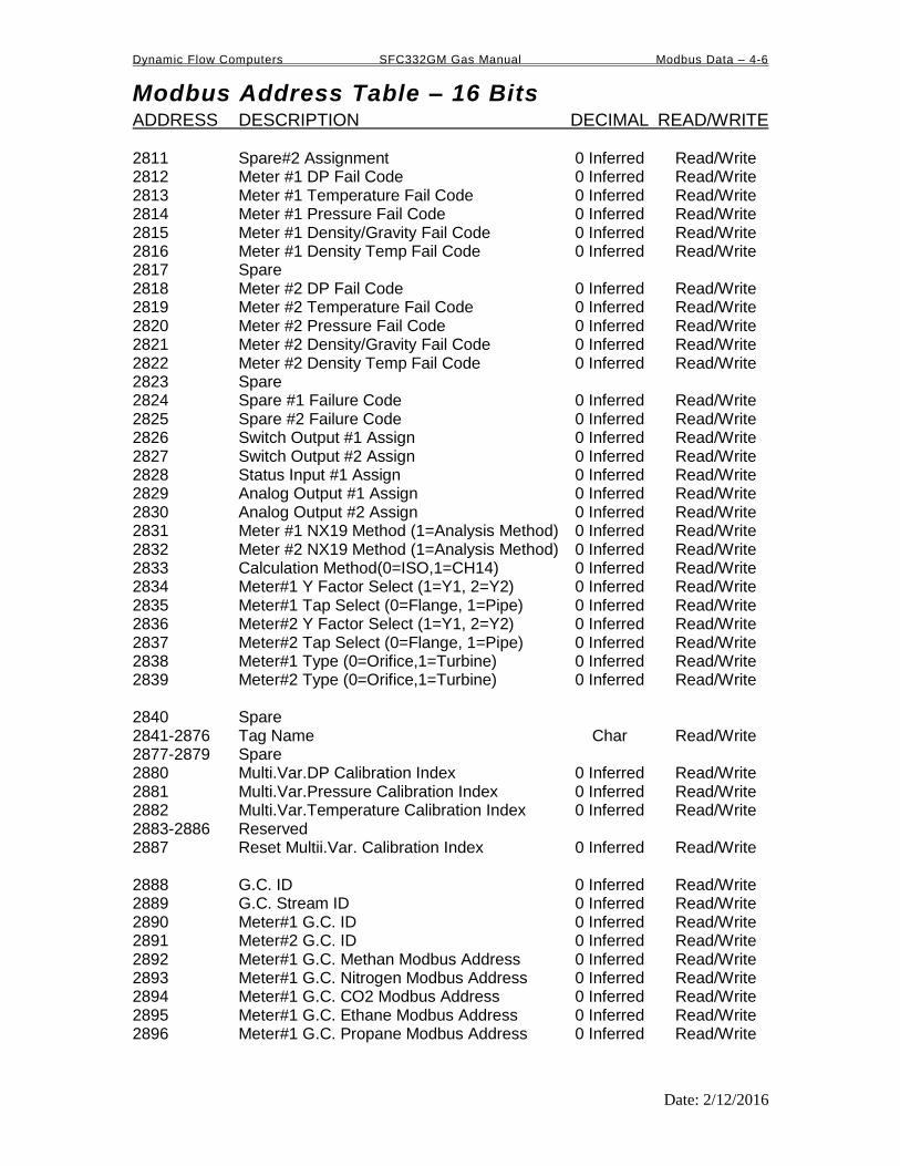
Dynamic Flow Computers SFC332GM Gas Manual Modbus Data – 4-6
Modbus Address Table – 16 Bits ADDRESS DESCRIPTION DECIMAL READ/WRITE
Date: 2/12/2016
2811 Spare#2 Assignment 0 Inferred Read/Write 2812 Meter #1 DP Fail Code 0 Inferred Read/Write 2813 Meter #1 Temperature Fail Code 0 Inferred Read/Write 2814 Meter #1 Pressure Fail Code 0 Inferred Read/Write 2815 Meter #1 Density/Gravity Fail Code 0 Inferred Read/Write 2816 Meter #1 Density Temp Fail Code 0 Inferred Read/Write 2817 Spare 2818 Meter #2 DP Fail Code 0 Inferred Read/Write 2819 Meter #2 Temperature Fail Code 0 Inferred Read/Write 2820 Meter #2 Pressure Fail Code 0 Inferred Read/Write 2821 Meter #2 Density/Gravity Fail Code 0 Inferred Read/Write 2822 Meter #2 Density Temp Fail Code 0 Inferred Read/Write 2823 Spare 2824 Spare #1 Failure Code 0 Inferred Read/Write 2825 Spare #2 Failure Code 0 Inferred Read/Write 2826 Switch Output #1 Assign 0 Inferred Read/Write 2827 Switch Output #2 Assign 0 Inferred Read/Write 2828 Status Input #1 Assign 0 Inferred Read/Write 2829 Analog Output #1 Assign 0 Inferred Read/Write 2830 Analog Output #2 Assign 0 Inferred Read/Write 2831 Meter #1 NX19 Method (1=Analysis Method) 0 Inferred Read/Write 2832 Meter #2 NX19 Method (1=Analysis Method) 0 Inferred Read/Write 2833 Calculation Method(0=ISO,1=CH14) 0 Inferred Read/Write 2834 Meter#1 Y Factor Select (1=Y1, 2=Y2) 0 Inferred Read/Write 2835 Meter#1 Tap Select (0=Flange, 1=Pipe) 0 Inferred Read/Write 2836 Meter#2 Y Factor Select (1=Y1, 2=Y2) 0 Inferred Read/Write 2837 Meter#2 Tap Select (0=Flange, 1=Pipe) 0 Inferred Read/Write 2838 Meter#1 Type (0=Orifice,1=Turbine) 0 Inferred Read/Write 2839 Meter#2 Type (0=Orifice,1=Turbine) 0 Inferred Read/Write 2840 Spare 2841-2876 Tag Name Char Read/Write 2877-2879 Spare 2880 Multi.Var.DP Calibration Index 0 Inferred Read/Write 2881 Multi.Var.Pressure Calibration Index 0 Inferred Read/Write 2882 Multi.Var.Temperature Calibration Index 0 Inferred Read/Write 2883-2886 Reserved 2887 Reset Multii.Var. Calibration Index 0 Inferred Read/Write 2888 G.C. ID 0 Inferred Read/Write 2889 G.C. Stream ID 0 Inferred Read/Write 2890 Meter#1 G.C. ID 0 Inferred Read/Write 2891 Meter#2 G.C. ID 0 Inferred Read/Write 2892 Meter#1 G.C. Methan Modbus Address 0 Inferred Read/Write 2893 Meter#1 G.C. Nitrogen Modbus Address 0 Inferred Read/Write 2894 Meter#1 G.C. CO2 Modbus Address 0 Inferred Read/Write 2895 Meter#1 G.C. Ethane Modbus Address 0 Inferred Read/Write 2896 Meter#1 G.C. Propane Modbus Address 0 Inferred Read/Write

Dynamic Flow Computers SFC332GM Gas Manual Modbus Data – 4-7
Modbus Address Table – 16 Bits ADDRESS DESCRIPTION DECIMAL READ/WRITE
Date: 2/12/2016
2896 Meter#1 G.C. Propane Modbus Address 0 Inferred Read/Write 2897 Meter#1 G.C. Water Modbus Address 0 Inferred Read/Write 2898 Meter#1 G.C. HS Modbus Address 0 Inferred Read/Write 2899 Meter#1 G.C. Hydrogen Modbus Address 0 Inferred Read/Write 2900 Meter#1 G.C. Carbon Monoxide Modbus Addr 0 Inferred Read/Write 2901 Meter#1 G.C. Oxygen Modbus Address 0 Inferred Read/Write 2902 Meter#1 G.C. i-Butane Modbus Address 0 Inferred Read/Write 2903 Meter#1 G.C. n-Butane Modbus Address 0 Inferred Read/Write 2904 Meter#1 G.C. i-Pentane Modbus Address 0 Inferred Read/Write 2905 Meter#1 G.C. n-Pentane Modbus Address 0 Inferred Read/Write 2906 Meter#1 G.C. n-Hexane Modbus Address 0 Inferred Read/Write 2907 Meter#1 G.C. n-Heptane Modbus Address 0 Inferred Read/Write 2908 Meter#1 G.C. n-Octane Modbus Address 0 Inferred Read/Write 2909 Meter#1 G.C. n-Nonane Modbus Address 0 Inferred Read/Write 2910 Meter#1 G.C. n-Decane Modbus Address 0 Inferred Read/Write 2911 Meter#1 G.C. Helium Modbus Address 0 Inferred Read/Write 2912 Meter#1 G.C. Argon Modbus Address 0 Inferred Read/Write 2913 Meter#1 G.C. SG Modbus Address 0 Inferred Read/Write 2914 Meter#1 G.C. BTU Modbus Address 0 Inferred Read/Write 2915-2932 Spare 2933 Switch Output #1 Assign 0 Inferred Read/Write 2934 Switch Output #2 Assign 0 Inferred Read/Write 2935 Switch Output #3 Assign 0 Inferred Read/Write 2936 Switch Output #4 Assign 0 Inferred Read/Write 2937 Switch Output #5 Assign 0 Inferred Read/Write 2938 Status Input #1 Assign 0 Inferred Read/Write 2939 Status Input #2 Assign 0 Inferred Read/Write 2940 Status Input #3 Assign 0 Inferred Read/Write 2941 Status Input #4 Assign 0 Inferred Read/Write

Dynamic Flow Computers SFC332GM Gas Manual Modbus Data – 4-8
Modbus Address Table – 16 Bits ADDRESS DESCRIPTION DECIMAL READ/WRITE
Date: 2/12/2016
3001 Version Number 2 Inferred Read 3002-3006 Spare 3007 Meter #1 Product Used 0 Inferred Read 3008-3011 Meter #1 ID 8 Chars Read 3012 Spare 3013 Meter #2 Product Used 0 Inferred Read 3014-3017 Meter #2 ID 8 Chars Read 3018 Flow Computer Unit Number 0 Inferred Read 3019 Disable Alarms (1=Yes) 0 Inferred Read 3020-3025 Spare 3026 Last Daily Report Request 0 Inferred Read/Write Set Request Date in 3787 Set Last Daily Report Request to 1 Daily Data Area in Location 3431-3703 3027 Last Monthly Report Request 0 Inferred Read/Write Set Last Monthly Report Request to 1 Monthly Area in Location 3431-3703 3028-3031 Reserved

Dynamic Flow Computers SFC332GM Gas Manual Modbus Data – 4-9
Modbus Address Table – 16 Bits ADDRESS DESCRIPTION DECIMAL READ/WRITE
Date: 2/12/2016
Scaled Data Area
3032 Meter #1 Gross Flowrate 0 Inferred Read 3033 Meter #1 Net Flowrate 0 Inferred Read 3034 Meter #1 Mass Flowrate 0 Inferred Read 3035 Meter #1 Energy Flowrate 0 Inferred Read 3036-3043 Spare 3044 Meter #2 Gross Flowrate 0 Inferred Read 3045 Meter #2 Net Flowrate 0 Inferred Read 3046 Meter #2 Mass Flowrate 0 Inferred Read 3047 Meter #2 Energy Flowrate 0 Inferred Read 3048-3055 Spare 3056 Spare #1 Data 0 Inferred Read 3057 Spare #2 Data 0 Inferred Read 3058 Meter #1 DP 0 Inferred Read 3059 Meter #1 Temperature 0 Inferred Read 3060 Meter #1 Pressure 0 Inferred Read 3061 Meter #1 Density 0 Inferred Read 3062 Meter #1 Dens.Temperature 0 Inferred Read 3063 Meter #2 DP 0 Inferred Read 3064 Meter #2 Temperature 0 Inferred Read 3065 Meter #2 Pressure 0 Inferred Read 3066 Meter #2 Density 0 Inferred Read 3067 Meter #2 Dens.Temperature 0 Inferred Read Scaled Data Area Ends
Modbus 16-bit Address Table Ends

Dynamic Flow Computers SFC332GM Gas Manual Modbus Data – 4-10
Date: 2/12/2016
3131 Meter #1 Gross Flow Rate 3 inferred Read 3133 Meter #1 Net Flow Rate 3 inferred Read 3135 Meter #1 Mass Flow Rate 3 inferred Read 3137 Meter #1 Energy Flow Rate 3 inferred Read 3139 Meter #1 DP Low 4 Inferred Read 3141 Meter #1 DP High 4 Inferred Read 3143 Meter #1 DP 4 Inferred Read 3145 Meter #1 Temperature 2 Inferred Read 3147 Meter #1 Pressure 2 Inferred Read 3149 Meter #1 Density 5 Inferred Read 3151 Meter #1 Density Temperature 2 Inferred Read 3153 Meter #1 Density.b 5 Inferred. Read 3155 Meter #1 SG 6 Inferred Read 3157 Meter #1 Y Factor 6 Inferred Read 3159 Meter #1 K/CD/LMF 6 Inferred Read 3161 Meter #1 FA 6 Inferred Read 3163 Meter #1 FPV 6 Inferred Read 3165 Meter #1 Meter Factor 4 Inferred Read 3167 Meter #1 Linear Factor 4 Inferred Read 3169 Spare 3171 Spare 3173 Meter #1 Forward Daily Gross Total 3 inferred Read 3175 Meter #1 Forward Daily Net Total 3 inferred Read 3177 Meter #1 Forward Daily Mass Total 3 Inferred Read 3179 Meter #1 Forward Daily Energy Total 3 Inferred Read 3181 Meter #1 Forward Cumulative Gross Total 3 Inferred Read 3183 Meter #1 Forward Cumulative Net Total 3 Inferred Read 3185 Meter #1 Forward Cumulative Mass Total 3 Inferred Read 3187 Meter #1 Forward Cumulative Energy Total 3 Inferred Read 3189 Meter #1 Reverse Daily Gross Total 3 Inferred Read 3191 Meter #1 Reverse Daily Net Total 3 Inferred Read 3193 Meter #1 Reverse Daily Mass Total 3 Inferred Read 3195 Meter #1 Reverse Daily Energy Total 3 Inferred Read 3197 Meter #1 Reverse Cumulative Gross Total 3 Inferred Read 3199 Meter #1 Reverse Cumulative Net Total 3 Inferred Read 3201 Meter #1 Reverse Cumulative Mass Total 3 Inferred Read 3203 Meter #1 Reverse Cumulative Energy Total 3 Inferred Read 3205 Meter #2 Gross Flow Rate 3 Inferred Read 3207 Meter #2 Net Flow Rate 3 Inferred Read 3209 Meter #2 Mass Flow Rate 3 Inferred Read 3211 Meter #2 Energy Flow Rate 3 Inferred Read 3213 Meter #2 DP Low 4 Inferred Read 3215 Meter #2 DP High 4 Inferred Read 3217 Meter #2 DP 4 Inferred Read 3219 Meter #2 Temperature 2 Inferred Read 3221 Meter #2 Pressure 2 Inferred Read

Dynamic Flow Computers SFC332GM Gas Manual Modbus Data – 4-11
Date: 2/12/2016
3223 Meter #2 Density 5 Inferred Read 3225 Meter #2 Density Temperature 2 Inferred Read 3227 Meter #2 Density.b 5 Inferred Read 3229 Meter #2 SG 6 Inferred Read 3231 Meter #2 Y Factor 6 Inferred Read 3233 Meter #2 K/CD/LMF 6 Inferred Read 3235 Meter #2 FA 6 Inferred Read 3237 Meter #2 FPV 6 Inferred Read 3239 Meter #2 Meter Factor 4 Inferred Read 3241 Meter #2 Linear Factor 4 Inferred Read 3243 Spare 3245 Spare 3247 Meter #2 Forward Daily Gross Total 3 Inferred Read 3249 Meter #2 Forward Daily Net Total 3 Inferred Read 3251 Meter #2 Forward Daily Mass Total 3 Inferred Read 3253 Meter #2 Forward Daily Energy Total 3 Inferred Read 3255 Meter #2 Forward Cumulative Gross Total 3 Inferred Read 3257 Meter #2 Forward Cumulative Net Total 3 Inferred Read 3259 Meter #2 Forward Cumulative Mass Total 3 Inferred Read 3261 Meter #2 Forward Cumulative Energy Total 3 Inferred Read 3263 Meter #2 Reverse Daily Gross Total 3 Inferred Read 3265 Meter #2 Reverse Daily Net Total 3 Inferred Read 3267 Meter #2 Reverse Daily Mass Total 3 Inferred Read 3269 Meter #2 Reverse Daily Energy Total 3 Inferred Read 3271 Meter #2 Reverse Cumulative Gross Total 3 Inferred Read 3273 Meter #2 Reverse Cumulative Net Total 3 Inferred Read 3275 Meter #2 Reverse Cumulative Mass Total 3 Inferred Read 3277 Meter #2 Reverse Cumulative Energy Total 3 Inferred Read 3279 Station Gross Flowrate 3 Inferred Read 3281 Station Net Flowrate 3 Inferred Read 3283 Station Mass Flowrate 3 Inferred Read 3285 Station Energy Flowrate 3 Inferred Read 3287 Station Forward Daily Gross Total 3 Inferred Read 3289 Station Forward Daily Net Total 3 Inferred Read 3291 Station Forward Daily Mass Total 3 Inferred Read 3293 Station Forward Daily. Energy Total 3 Inferred Read 3295 Station Forward Cum. Gross Total 3 Inferred Read 3297 Station Forward Cum. Net Total 3 Inferred Read 3299 Station Forward Cum. Mass Total 3 Inferred Read 3301 Station Forward Cum. Energy Total 3 Inferred Read 3303 Station Reverse Daily Gross Total 3 Inferred Read 3305 Station Reverse Daily Net Total 3 Inferred Read 3307 Station Reverse Daily Mass Total 3 Inferred Read 3309 Station Reverse Daily. Energy Total 3 Inferred Read
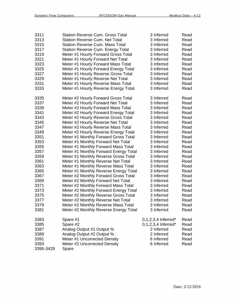
Dynamic Flow Computers SFC332GM Gas Manual Modbus Data – 4-12
Date: 2/12/2016
3311 Station Reverse Cum. Gross Total 3 Inferred Read 3313 Station Reverse Cum. Net Total 3 Inferred Read 3315 Station Reverse Cum. Mass Total 3 Inferred Read 3317 Station Reverse Cum. Energy Total 3 Inferred Read 3319 Meter #1 Hourly Forward Gross Total 3 Inferred Read 3321 Meter #1 Hourly Forward Net Total 3 Inferred Read 3323 Meter #1 Hourly Forward Mass Total 3 Inferred Read 3325 Meter #1 Hourly Forward Energy Total 3 Inferred Read 3327 Meter #1 Hourly Reverse Gross Total 3 Inferred Read 3329 Meter #1 Hourly Reverse Net Total 3 Inferred Read 3331 Meter #1 Hourly Reverse Mass Total 3 Inferred Read 3333 Meter #1 Hourly Reverse Energy Total 3 Inferred Read 3335 Meter #2 Hourly Forward Gross Total 3 Inferred Read 3337 Meter #2 Hourly Forward Net Total 3 Inferred Read 3339 Meter #2 Hourly Forward Mass Total 3 Inferred Read 3341 Meter #2 Hourly Forward Energy Total 3 Inferred Read 3343 Meter #2 Hourly Reverse Gross Total 3 Inferred Read 3345 Meter #2 Hourly Reverse Net Total 3 Inferred Read 3347 Meter #2 Hourly Reverse Mass Total 3 Inferred Read 3349 Meter #2 Hourly Reverse Energy Total 3 Inferred Read 3351 Meter #1 Monthly Forward Gross Total 3 Inferred Read 3353 Meter #1 Monthly Forward Net Total 3 Inferred Read 3355 Meter #1 Monthly Forward Mass Total 3 Inferred Read 3357 Meter #1 Monthly Forward Energy Total 3 Inferred Read 3359 Meter #1 Monthly Reverse Gross Total 3 Inferred Read 3361 Meter #1 Monthly Reverse Net Total 3 Inferred Read 3363 Meter #1 Monthly Reverse Mass Total 3 Inferred Read 3365 Meter #1 Monthly Reverse Energy Total 3 Inferred Read 3367 Meter #2 Monthly Forward Gross Total 3 Inferred Read 3369 Meter #2 Monthly Forward Net Total 3 Inferred Read 3371 Meter #2 Monthly Forward Mass Total 3 Inferred Read 3373 Meter #2 Monthly Forward Energy Total 3 Inferred Read 3375 Meter #2 Monthly Reverse Gross Total 3 Inferred Read 3377 Meter #2 Monthly Reverse Net Total 3 Inferred Read 3379 Meter #2 Monthly Reverse Mass Total 3 Inferred Read 3381 Meter #2 Monthly Reverse Energy Total 3 Inferred Read 3383 Spare #1 0,1,2,3,4 Inferred* Read 3385 Spare #2 0,1,2,3,4 Inferred* Read 3387 Analog Output #1 Output % 2 Inferred Read 3389 Analog Output #2 Output % 2 Inferred Read 3391 Meter #1 Uncorrected Density 6 Inferred Read 3393 Meter #2 Uncorrected Density 6 Inferred Read 3395-3429 Spare

Dynamic Flow Computers SFC332GM Gas Manual Modbus Data – 4-13
Date: 2/12/2016
Last Daily or Monthly Data Area
Set Request Date (mm/dd/yy) (3787) Set Last Daily Report Request (3026) to 1) Daily Data Area in Location 3431-3703 Set Last Monthly Report Request (3027) to 1) Monthly Data Area in Location 3431-3703 3431 Batch Type/Disp/Bank/Station Flag 0 Inferred Read 3433 Meter #1 Density Calculation Type 0 Inferred Read 3435 Meter #2 Density Calculation Type 0 Inferred Read 3437 Day/Month Start Date 0 Inferred Read 3439 Day/Month Start Time 0 Inferred Read 3441 Day/Month End Date 0 Inferred Read 3443 Day/Month End Time 0 Inferred Read 3445 Meter #1 Cum. Forward Gross Total 3 Inferred Read 3447 Meter #1 Cum. Forward Net Total 3 Inferred Read 3449 Meter #1 Cum. Forward Mass Total 3 Inferred Read 3451 Meter #1 Cum. Forward Energy Total 3 Inferred Read 3453 Meter #1 Daily/Monthly Forward Gross Total 3 Inferred Read 3455 Meter #1 Daily/Monthly Forward Net Total 3 Inferred Read 3457 Meter #1 Daily/Monthly Forward Mass Total 3 Inferred Read 3459 Meter #1 Daily/Monthly Forward Energy Total 3 Inferred Read 3461 Meter #1 Forward FWA DP 4 Inferred Read 3463 Meter #1 Forward FWA Temperature 2 Inferred Read 3465 Meter #1 Forward FWA Pressure 2 Inferred Read 3467 Meter #1 Forward FWA Density 5 Inferred Read 3469 Meter #1 Forward FWA Density Temp 2 Inferred Read 3471 Meter #1 Forward FWA Dens.b 5 Inferred Read 3473 Meter #1 Forward FWA SG 6 Inferred Read 3475 Meter #1 Forward FWA Y Factor 6 Inferred Read 3477 Meter #1 Forward FWA K/CD/lMF 6 Inferred Read 3479 Meter #1 Forward FWA FA 6 Inferred Read 3481 Meter #1 Forward FWA FPV 6 Inferred Read 3483 Meter #1 Forward FWA LMF 4 Inferred Read 3485 Meter #1 Forward FWA Linear Factor 4 Inferred Read 3487 Meter #1 Cum. Reverse Gross Total 3 Inferred Read 3489 Meter #1 Cum. Reverse Net Total 3 Inferred Read 3491 Meter #1 Cum. Reverse Mass Total 3 Inferred Read 3493 Meter #1 Cum. Reverse Energy Total 3 Inferred Read 3495 Meter #1 Daily/Monthly Reverse Gross Total 3 Inferred Read 3497 Meter #1 Daily/Monthly Reverse Net Total 3 Inferred Read 3499 Meter #1 Daily/Monthly Reverse Mass Total 3 Inferred Read 3501 Meter #1 Daily/Monthly Reverse Energy Total 3 Inferred Read 3503 Meter #1 Reverse FWA DP 4 Inferred Read 3505 Meter #1 Reverse FWA Temperature 2 Inferred Read 3507 Meter #1 Reverse FWA Pressure 2 Inferred Read 3509 Meter #1 Reverse FWA Density 5 Inferred Read

Dynamic Flow Computers SFC332GM Gas Manual Modbus Data – 4-14
Date: 2/12/2016
3511 Meter #1 Reverse FWA Density Temp 2 Inferred Read 3513 Meter #1 Reverse FWA Dens.b 5 Inferred Read 3515 Meter #1 Reverse FWA SG 6 Inferred Read 3517 Meter #1 Reverse FWA Y Factor 6 Inferred Read 3519 Meter #1 Reverse FWA K/CD 6 Inferred Read 3521 Meter #1 Reverse FWA FA 6 Inferred Read 3523 Meter #1 Reverse FWA FPV 6 Inferred Read 3525 Meter #1 Reverse FWA Linear Factor 4 Inferred Read 3527 Meter #1 Reverse FWA Meter Factor 4 Inferred Read 3529-3531 Meter #1 ID 8 Chars. Read 3533 Meter #1 Pipe ID 4 Inferred Read 3535 Meter #1 Orifice ID 4 Inferred Read 3537 Meter #1 Density Correction Factor 5 Inferred Read 3539 Meter #1 Density Dry Air 5 Inferred Read 3541 Meter #1 Calculation Type 0 Inferred Read 3543 Meter #1 Heating Value BTU/FT3 4 Inferred Read 3545 Meter #1 K Factor 3 Inferred Read 3547-3553 Spare 3555 Meter #2 Cum. Forward Gross Total 3 Inferred Read 3557 Meter #2 Cum. Forward Net Total 3 Inferred Read 3559 Meter #2 Cum. Forward Mass Total 3 Inferred Read 3561 Meter #2 Cum. Forward Energy Total 3 Inferred Read 3563 Meter #2 Daily/Monthly Forward Gross Total 3 Inferred Read 3565 Meter #2 Daily/Monthly Forward Net Total 3 Inferred Read 3567 Meter #2 Daily/Monthly Forward Mass Total 3 Inferred Read 3569 Meter #2 Daily/Monthly Forward Energy Total 3 Inferred Read 3571 Meter #2 Forward FWA DP 4 Inferred Read 3573 Meter #2 Forward FWA Temperature 2 Inferred Read 3575 Meter #2 Forward FWA Pressure 2 Inferred Read 3577 Meter #2 Forward FWA Density 5 Inferred Read 3579 Meter #2 Forward FWA Density Temp 2 Inferred Read 3581 Meter #2 Forward FWA Density.b 5 Inferred Read 3583 Meter #2 Forward FWA SG 6 Inferred Read 3585 Meter #2 Forward FWA Y Factor 6 Inferred Read 3587 Meter #2 Forward FWA K/CD 6 Inferred Read 3589 Meter #2 Forward FWA FA 6 Inferred Read 3591 Meter #2 Forward FWA FPV 6 Inferred Read 3593 Meter #2 Forward FWA Linear Factor 4 Inferred Read 3595 Meter #2 Forward FWA Meter Factor 4 Inferred Read 3597 Meter #2 Cum. Reverse Gross Total 3 Inferred Read 3599 Meter #2 Cum. Reverse Net Total 3 Inferred Read 3601 Meter #2 Cum. Reverse Mass Total 3 Inferred Read 3603 Meter #2 Cum. Reverse Energy Total 3 Inferred Read 3605 Meter #2 Daily/Monthly Reverse Gross Total 3 Inferred Read 3607 Meter #2 Daily/Monthly Reverse Net Total 3 Inferred Read 3609 Meter #2 Daily/Monthly Reverse Mass Total 3 Inferred Read 3611 Meter #2 Daily/Monthly Reverse Energy Total 3 Inferred Read

Dynamic Flow Computers SFC332GM Gas Manual Modbus Data – 4-15
Date: 2/12/2016
3613 Meter #2 Reverse FWA DP 4 Inferred Read 3615 Meter #2 Reverse FWA Temperature 2 Inferred Read 3617 Meter #2 Reverse FWA Pressure 2 Inferred Read 3619 Meter #2 Reverse FWA Density 5 Inferred Read 3621 Meter #2 Reverse FWA Density Temp 2 Inferred Read 3623 Meter #2 Reverse FWA Density.b 5 Inferred Read 3625 Meter #2 Reverse FWA SG 6 Inferred Read 3627 Meter #2 Reverse FWA Y Factor 6 Inferred Read 3629 Meter #2 Reverse FWA K/CD 6 Inferred Read 3631 Meter #2 Reverse FWA FA 6 Inferred Read 3633 Meter #2 Reverse FWA FPV 6 Inferred Read 3635 Meter #2 Reverse FWA Linear Factor 4 Inferred Read 3637 Meter #2 Reverse FWA Meter Factor 4 Inferred Read 3639-3641 Meter #2 ID 8 Chars. Read 3643 Meter #2 Pipe ID 4 Inferred Read 3645 Meter #2 Orifice ID 4 Inferred Read 3647 Meter #2 Density Correction Factor 5 Inferred Read 3649 Meter #2 Density Dry Air 5 Inferred Read 3651 Meter #2 Calculation Type 0 Inferred Read 3653 Meter #2 Heating Value BTU/FT3 4 Inferred Read 3655 Meter #2 K Factor 3 Inferred Read 3657-3667 Spare 3669 Station Cum. Forward Gross Total 3 Inferred Read 3671 Station Cum. Forward Net Total 3 Inferred Read 3673 Station Cum. Forward Mass Total 3 Inferred Read 3675 Station Cum Forward Energy Total 3 Inferred Read 3677 Station Daily/Monthly Forward Gross Total 3 Inferred Read 3679 Station Daily/Monthly Forward Net Total 3 Inferred Read 3681 Station Daily/Monthly Forward Mass Total 3 Inferred Read 3683 Station Daily/Monthly Forward Energy Total 3 Inferred Read 3685 Station Cum. Reverse Gross Total 3 Inferred Read 3687 Station Cum. Reverse Net Total 3 Inferred Read 3689 Station Cum. Reverse Mass Total 3 Inferred Read 3691 Station Cum. Reverse Energy Total 3 Inferred Read 3693 Station Daily/Monthly Reverse Gross Total 3 Inferred Read 3695 Station Daily/Monthly Reverse Net Total 3 Inferred Read 3697 Station Daily/Monthly Reverse Mass Total 3 Inferred Read 3699 Station Daily/Monthly Reverse Energy Total 3 Inferred Read 3701 Spare #1 4 Inferred Read 3703 Spare #2 4 Inferred Read 3705-3765 Spare Last Daily or Monthly Data Area Ends
Dynamic Flow Computers SFC332GM Gas Manual Modbus Data – 4-16
Date: 2/12/2016
3767-3785 Spare 3787 Request Start Date 0 Inferred Read/Write 3789-4149 Reserved 4151 Meter #1 Densitometer Period 3 Inferred Read 4153 Meter #2 Densitometer Period 3 Inferred Read 4155-4199 Spare 4201 Date (MMDDYY) 0 Inferred Read/Write 4203 Time (HHMMSS) 0 Inferred Read/Write 4205-4243 Spare NX19 Method
4245 Meter#1 Mol Percentage of Methane 4 Inferred Read/Write 4247 Meter#1 Mol Percentage of Ethane 4 Inferred Read/Write 4249 Meter#1 Mol Percentage of Propane 4 Inerred Read/Write 4251 Meter#1 Mol Percentage of Iso-Butane 4 Inferred Read/Write 4253 Meter#1 Mol Percentage of N-Butane 4 Inferred Read/Write 4255 Meter#1 Mol Percentage of Iso-Pentane 4 Inferred Read/Write 4257 Meter#1 Mol Percentage of N-Pentane 4 Inferred Read/Write 4259 Meter#1 Mol Percentage of N-Hexane 4 Inferred Read/Write 4261 Meter#1 Mol Percentage of Heptane 4 Inferred Read/Write 4263 Meter#1 Mol Percentage of N-Octane 4 Inferred Read/Write 4265 Meter#1 Mol Percentage of CO2 4 Inferred Read/Write 4267 Meter#1 Mol Percentage of N2 4 Inferred Read/Write 4269-4285 Spare 4287 Meter#2 Mol Percentage of Methane 4 Inferred Read/Write 4289 Meter#2 Mol Percentage of Ethane 4 Inferred Read/Write 4291 Meter#2 Mol Percentage of Propane 4 Inerred Read/Write 4293 Meter#2 Mol Percentage of Iso-Butane 4 Inferred Read/Write 4295 Meter#2 Mol Percentage of N-Butane 4 Inferred Read/Write 4297 Meter#2 Mol Percentage of Iso-Pentane 4 Inferred Read/Write 4299 Meter#2 Mol Percentage of N-Pentane 4 Inferred Read/Write 4301 Meter#2 Mol Percentage of N-Hexane 4 Inferred Read/Write 4303 Meter#2 Mol Percentage of Heptane 4 Inferred Read/Write 4305 Meter#2 Mol Percentage of N-Octane 4 Inferred Read/Write 4307 Meter#2 Mol Percentage of CO2 4 Inferred Read/Write 4309 Meter#2 Mol Percentage of N2 4 Inferred Read/Write 4311-4327 Spare

Dynamic Flow Computers SFC332GM Gas Manual Modbus Data – 4-17
Date: 2/12/2016
AGA 8 GROSS METHOD 1
4245 Meter#1 Mol % of Carbon Dioxide 4 Inferred Read/Write 4247 Meter#1 Mol % of Hydrogen 4 Inferred Read/Write 4249 Meter#1 Mol % of Carbon Monoxide 4 Inferred Read/Write 4251-4285 Spare 4287 Meter#2 Mol % of Carbon Dioxide 4 Inferred Read/Write 4289 Meter#2 Mol % of Hydrogen 4 Inferred Read/Write 4291 Meter#2 Mol % of Carbon Monoxide 4 Inferred Read/Write 4293-4327 Spare AGA 8 GROSS METHOD 2
4245 Meter#1 Mol % of Nitrogen 4 Inferred Read/Write 4247 Meter#1 Mol % of Carbon Dioxide 4 Inferred Read/Write 4249 Meter#1 Mol % of Hydrogen 4 Inferred Read/Write 4251 Meter#1 Mol % of Carbon Monoxide 4 Inferred Read/Write 4253-4285 Spare 4287 Meter#2 Mol % of Nitrogen 4 Inferred Read/Write 4289 Meter#2 Mol % of Carbon Dioxide 4 Inferred Read/Write 4291 Meter#2 Mol % of Hydrogen 4 Inferred Read/Write 4293 Meter#2 Mol % of Carbon Monoxide 4 Inferred Read/Write 4295-4327 Spare
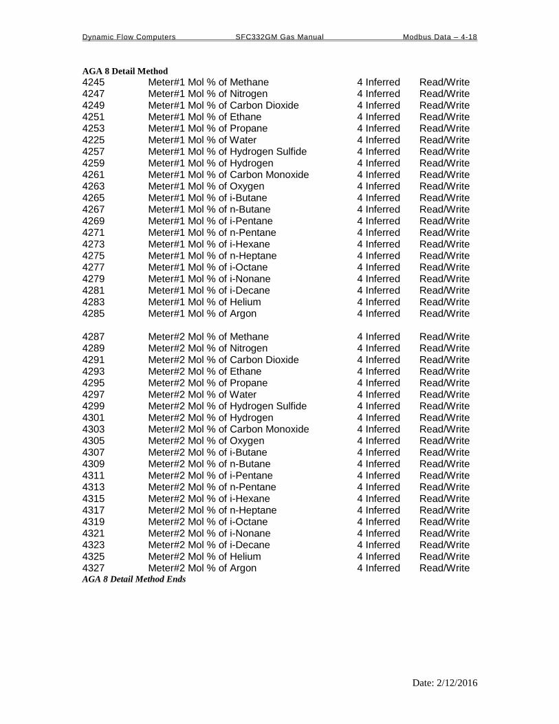
Dynamic Flow Computers SFC332GM Gas Manual Modbus Data – 4-18
Date: 2/12/2016
AGA 8 Detail Method
4245 Meter#1 Mol % of Methane 4 Inferred Read/Write 4247 Meter#1 Mol % of Nitrogen 4 Inferred Read/Write 4249 Meter#1 Mol % of Carbon Dioxide 4 Inferred Read/Write 4251 Meter#1 Mol % of Ethane 4 Inferred Read/Write 4253 Meter#1 Mol % of Propane 4 Inferred Read/Write 4225 Meter#1 Mol % of Water 4 Inferred Read/Write 4257 Meter#1 Mol % of Hydrogen Sulfide 4 Inferred Read/Write 4259 Meter#1 Mol % of Hydrogen 4 Inferred Read/Write 4261 Meter#1 Mol % of Carbon Monoxide 4 Inferred Read/Write 4263 Meter#1 Mol % of Oxygen 4 Inferred Read/Write 4265 Meter#1 Mol % of i-Butane 4 Inferred Read/Write 4267 Meter#1 Mol % of n-Butane 4 Inferred Read/Write 4269 Meter#1 Mol % of i-Pentane 4 Inferred Read/Write 4271 Meter#1 Mol % of n-Pentane 4 Inferred Read/Write 4273 Meter#1 Mol % of i-Hexane 4 Inferred Read/Write 4275 Meter#1 Mol % of n-Heptane 4 Inferred Read/Write 4277 Meter#1 Mol % of i-Octane 4 Inferred Read/Write 4279 Meter#1 Mol % of i-Nonane 4 Inferred Read/Write 4281 Meter#1 Mol % of i-Decane 4 Inferred Read/Write 4283 Meter#1 Mol % of Helium 4 Inferred Read/Write 4285 Meter#1 Mol % of Argon 4 Inferred Read/Write 4287 Meter#2 Mol % of Methane 4 Inferred Read/Write 4289 Meter#2 Mol % of Nitrogen 4 Inferred Read/Write 4291 Meter#2 Mol % of Carbon Dioxide 4 Inferred Read/Write 4293 Meter#2 Mol % of Ethane 4 Inferred Read/Write 4295 Meter#2 Mol % of Propane 4 Inferred Read/Write 4297 Meter#2 Mol % of Water 4 Inferred Read/Write 4299 Meter#2 Mol % of Hydrogen Sulfide 4 Inferred Read/Write 4301 Meter#2 Mol % of Hydrogen 4 Inferred Read/Write 4303 Meter#2 Mol % of Carbon Monoxide 4 Inferred Read/Write 4305 Meter#2 Mol % of Oxygen 4 Inferred Read/Write 4307 Meter#2 Mol % of i-Butane 4 Inferred Read/Write 4309 Meter#2 Mol % of n-Butane 4 Inferred Read/Write 4311 Meter#2 Mol % of i-Pentane 4 Inferred Read/Write 4313 Meter#2 Mol % of n-Pentane 4 Inferred Read/Write 4315 Meter#2 Mol % of i-Hexane 4 Inferred Read/Write 4317 Meter#2 Mol % of n-Heptane 4 Inferred Read/Write 4319 Meter#2 Mol % of i-Octane 4 Inferred Read/Write 4321 Meter#2 Mol % of i-Nonane 4 Inferred Read/Write 4323 Meter#2 Mol % of i-Decane 4 Inferred Read/Write 4325 Meter#2 Mol % of Helium 4 Inferred Read/Write 4327 Meter#2 Mol % of Argon 4 Inferred Read/Write AGA 8 Detail Method Ends

Dynamic Flow Computers SFC332GM Gas Manual Modbus Data – 4-19
Date: 2/12/2016
4329 Meter #1 Heating Value 4 Inferred Read/Write 4331 Meter #2 Heating Value 4 Inferred Read/Write 4333 Meter #1 FPV Override 6 Inferred Read/Write 4335 Meter #2 FPV Override 6 Inferred Read/Write 4337 Meter #1 Temperature Override 2 Inferred Read/Write 4339 Meter #2 Temperature Override 2 Inferred Read/Write 4341 Meter #1 Pressure Override 4 Inferred Read/Write 4343 Meter #2 Pressure Override 4 Inferred Read/Write 4345 Meter #1 Base Density Override 6 Inferred Read/Write 4347 Meter #2 Base Density Override 6 Inferred Read/Write 4349 Meter #1 DP Cut Off 4 Inferred Read/Write 4351 Meter #1 Flowrate Low Limit 3 Inferred Read/Write 4353 Meter #1 Flowrate High Limit 3 Inferred Read/Write 4355 Meter #1 Pipe ID 4 Inferred Read/Write 4357 Meter #1 Orifice ID 4 Inferred Read/Write 4359 Meter #2 DP Cut Off 4 Inferred Read/Write 4361 Meter #2 Flowrate Low Limit 3 Inferred Read/Write 4363 Meter #2 Flowrate High Limit 3 Inferred Read/Write 4365 Meter #2 Pipe ID 4 Inferred Read/Write 4367 Meter #2 Orifice ID 4 Inferred Read/Write 4369 Meter #1 Density Dry Air 5 Inferred Read/Write 4371 Meter #1 Relative Density 5 Inferred Read/Write 4373 Meter #1 Ratio of Heat 4 Inferred Read/Write 4375 Meter #1 Viscosity 6 Inferred Read/Write 4377 Meter #1 Pipe Thermal E-6 2 Inferred Read/Write 4379 Meter #1 Orifice Thermal E-6 2 Inferred Read/Write 4381 Meter #1 Reference Temp of Pipe 2 Inferred Read/Write 4383 Meter #1 Reference Temp of Orifice 2 Inferred Read/Write 4385 Meter #2 Density Dry Air 5 Inferred Read/Write 4387 Meter #2 Relative Density 5 Inferred Read/Write 4389 Meter #2 Ratio of Heat 4 Inferred Read/Write 4391 Meter #2 Viscosity 6 Inferred Read/Write 4393 Meter #2 Pipe Thermal E-6 2 Inferred Read/Write 4395 Meter #2 Pipe Thermal E-6 2 Inferred Read/Write 4397 Meter #2 Refernece Temp of Pipe 2 Inferred Read/Write 4399 Meter #2 Reference Temp of Orifice 2 Inferred Read/Write 4401 Meter #1 DP Switch High % 2 Inferred Read/Write 4403 Meter #2 DP Switch Low % 2 Inferred Read/Write 4405 Meter #1 K Factor 3 Inferred Read/Write 4407 Meter #1 Meter Factor 4 Inferred Read/Write 4409 Meter #2 K Factor 3 Inferred Read/Write 4411 Meter #2 Meter Factor 4 Inferred Read/Write
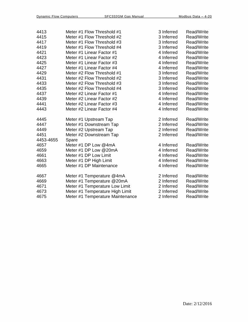
Dynamic Flow Computers SFC332GM Gas Manual Modbus Data – 4-20
Date: 2/12/2016
4413 Meter #1 Flow Threshold #1 3 Inferred Read/Write 4415 Meter #1 Flow Threshold #2 3 Inferred Read/Write 4417 Meter #1 Flow Threshold #3 3 Inferred Read/Write 4419 Meter #1 Flow Threshold #4 3 Inferred Read/Write 4421 Meter #1 Linear Factor #1 4 Inferred Read/Write 4423 Meter #1 Linear Factor #2 4 Inferred Read/Write 4425 Meter #1 Linear Factor #3 4 Inferred Read/Write 4427 Meter #1 Linear Factor #4 4 Inferred Read/Write 4429 Meter #2 Flow Threshold #1 3 Inferred Read/Write 4431 Meter #2 Flow Threshold #2 3 Inferred Read/Write 4433 Meter #2 Flow Threshold #3 3 Inferred Read/Write 4435 Meter #2 Flow Threshold #4 3 Inferred Read/Write 4437 Meter #2 Linear Factor #1 4 Inferred Read/Write 4439 Meter #2 Linear Factor #2 4 Inferred Read/Write 4441 Meter #2 Linear Factor #3 4 Inferred Read/Write 4443 Meter #2 Linear Factor #4 4 Inferred Read/Write 4445 Meter #1 Upstream Tap 2 Inferred Read/Write 4447 Meter #1 Downstream Tap 2 Inferred Read/Write 4449 Meter #2 Upstream Tap 2 Inferred Read/Write 4451 Meter #2 Downstream Tap 2 Inferred Read/Write 4453-4655 Spare 4657 Meter #1 DP Low @4mA 4 Inferred Read/Write 4659 Meter #1 DP Low @20mA 4 Inferred Read/Write 4661 Meter #1 DP Low Limit 4 Inferred Read/Write 4663 Meter #1 DP High Limit 4 Inferred Read/Write 4665 Meter #1 DP Maintenance 4 Inferred Read/Write 4667 Meter #1 Temperature @4mA 2 Inferred Read/Write 4669 Meter #1 Temperature @20mA 2 Inferred Read/Write 4671 Meter #1 Temperature Low Limit 2 Inferred Read/Write 4673 Meter #1 Temperature High Limit 2 Inferred Read/Write 4675 Meter #1 Temperature Maintenance 2 Inferred Read/Write

Dynamic Flow Computers SFC332GM Gas Manual Modbus Data – 4-21
Date: 2/12/2016
4677 Meter #1 Pressure @4mA 2 Inferred Read/Write 4679 Meter #1 Pressure @20mA 2 Inferred Read/Write 4681 Meter #1 Pressure Low Limit 2 Inferred Read/Write 4683 Meter #1 Pressure High Limit 2 Inferred Read/Write 4685 Meter #1 Pressure Maintenance 2 Inferred Read/Write 4687 Meter #1 Density @4mA 5 Inferred Read/Write 4689 Meter #1 Density @20mA 5 Inferred Read/Write 4691 Meter #1 Density Low Limit 5 Inferred Read/Write 4693 Meter #1 Density High Limit 5 Inferred Read/Write 4695 Meter #1 Density Maintenance 5 Inferred Read/Write 4697 Meter #1 Dens.Temp @4mA 2 Inferred Read/Write 4699 Meter #1 Dens.Temp @20mA 2 Inferred Read/Write 4701 Meter #1 Dens.Temp Low Limit 2 Inferred Read/Write 4703 Meter #1 Dens.Temp High Limit 2 Inferred Read/Write 4705 Meter #1 Dens.Temp Maintenance 2 Inferred Read/Write 4707 Meter #1 DP High @4mA 4 Inferred Read/Write 4709 Meter #1 DP High @20mA 4 Inferred Read/Write 4711-4715 Spare 4717 Meter #1 Density Correction Factor 5 Inferred Read/Write 4719 Meter #1 Dens.Period Low Limit 3 Inferred Read/Write 4721 Meter #1 Dens.Period High Limit 3 Inferred Read/Write 4723-4725 Spare 4727 Meter #2 DP Low @4mA 4 Inferred Read/Write 4729 Meter #2 DP Low @20mA 4 Inferred Read/Write 4731 Meter #2 DP Low Limit 4 Inferred Read/Write 4733 Meter #2 DP High Limit 4 Inferred Read/Write 4735 Meter #2 DP Maintenance 4 Inferred Read/Write 4737 Meter #2 Temperature @4mA 2 Inferred Read/Write 4739 Meter #2 Temperature @20mA 2 Inferred Read/Write 4741 Meter #2 Temperature Low Limit 2 Inferred Read/Write 4743 Meter #2 Temperature High Limit 2 Inferred Read/Write 4745 Meter #2 Temperature Maintenance 2 Inferred Read/Write 4747 Meter #2 Pressure @4mA 2 Inferred Read/Write 4749 Meter #2 Pressure @20mA 2 Inferred Read/Write 4751 Meter #2 Pressure Low Limit 2 Inferred Read/Write 4753 Meter #2 Pressure High Limit 2 Inferred Read/Write 4755 Meter #2 Pressure Maintenance 2 Inferred Read/Write 4757 Meter #2 Density @4mA 5 Inferred Read/Write 4759 Meter #2 Density @20mA 5 Inferred Read/Write 4761 Meter #2 Density Low Limit 5 Inferred Read/Write 4763 Meter #2 Density High Limit 5 Inferred Read/Write 4765 Meter #2 Density Maintenance 5 Inferred Read/Write

Dynamic Flow Computers SFC332GM Gas Manual Modbus Data – 4-22
Date: 2/12/2016
4767 Meter #2 Dens.Temp @4mA 2 Inferred Read/Write 4769 Meter #2 Dens.Temp @20mA 2 Inferred Read/Write 4771 Meter #2 Dens.Temp Low Limit 2 Inferred Read/Write 4773 Meter #2 Dens.Temp High Limit 2 Inferred Read/Write 4775 Meter #2 Dens.Temp Maintenance 2 Inferred Read/Write 4777 Meter #2 DP High @4mA 4 Inferred Read/Write 4779 Meter #2 DP High @20mA 4 Inferred Read/Write 4781-4785 Spare 4787 Meter #2 Density Correction Factor 5 Inferred Read/Write 4789 Meter #2 Dens.Period Low Limit 3 Inferred Read/Write 4791 Meter #2 Dens.Period High Limit 3 Inferred Read/Write 4793-4796 Spare 4797 Spare#1 @4mA 0,1,2 3,4 Inferred* Read/Write 4799 Spare#1 @20mA 0,1,2 3,4 Inferred* Read/Write 4801 Spare#1 Lo-Limit 0,1,2 3,4 Inferred* Read/Write 4803 Spare#1 Hi-Limit 0,1,2 3,4 Inferred* Read/Write 4805 Spare#1 Maintenance 0,1,2 3,4 Inferred* Read/Write 4807 Spare#2 @4mA 0,1,2 3,4 Inferred* Read/Write 4809 Spare#2 @20mA 0,1,2 3,4 Inferred* Read/Write 4811 Spare#2 Lo-Limit 0,1,2 3,4 Inferred* Read/Write 4813 Spare#2 Hi-Limit 0,1,2 3,4 Inferred* Read/Write 4815 Spare#2 Maintenance 0,1,2 3,4 Inferred* Read/Write 4817 Spare 4819 Base Temperature 3 Inferred Read/Write 4821 Base Pressure 5 Inferred Read/Write 4823 Run Switch Low Set Point 2 Inferred Read/Write 4825 Run Switch High Set Point 2 Inferred Read/Write 4827 Automapheric Pressure PSIA 3 Inferred Read/Write 4829 Pulse Output Volume #1 Pulses/Unit 3 Inferred Read/Write 4831 Pulse Output Volume #2 Pulses/Unit 3 Inferred Read/Write 4833 Analog Output #1 at 4 mA 4835 Analog Output #1 at 20 mA 4837 Analog Output #2 at 4 mA 4839 Analog Output #2 at 20 mA
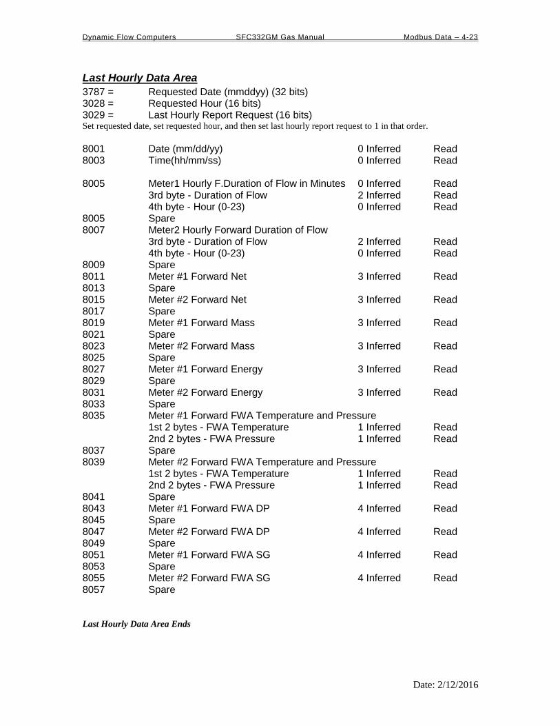
Dynamic Flow Computers SFC332GM Gas Manual Modbus Data – 4-23
Date: 2/12/2016
Last Hourly Data Area
3787 = Requested Date (mmddyy) (32 bits) 3028 = Requested Hour (16 bits) 3029 = Last Hourly Report Request (16 bits) Set requested date, set requested hour, and then set last hourly report request to 1 in that order.
8001 Date (mm/dd/yy) 0 Inferred Read 8003 Time(hh/mm/ss) 0 Inferred Read 8005 Meter1 Hourly F.Duration of Flow in Minutes 0 Inferred Read 3rd byte - Duration of Flow 2 Inferred Read 4th byte - Hour (0-23) 0 Inferred Read 8005 Spare 8007 Meter2 Hourly Forward Duration of Flow 3rd byte - Duration of Flow 2 Inferred Read 4th byte - Hour (0-23) 0 Inferred Read 8009 Spare 8011 Meter #1 Forward Net 3 Inferred Read 8013 Spare 8015 Meter #2 Forward Net 3 Inferred Read 8017 Spare 8019 Meter #1 Forward Mass 3 Inferred Read 8021 Spare 8023 Meter #2 Forward Mass 3 Inferred Read 8025 Spare 8027 Meter #1 Forward Energy 3 Inferred Read 8029 Spare 8031 Meter #2 Forward Energy 3 Inferred Read 8033 Spare 8035 Meter #1 Forward FWA Temperature and Pressure 1st 2 bytes - FWA Temperature 1 Inferred Read 2nd 2 bytes - FWA Pressure 1 Inferred Read 8037 Spare 8039 Meter #2 Forward FWA Temperature and Pressure 1st 2 bytes - FWA Temperature 1 Inferred Read 2nd 2 bytes - FWA Pressure 1 Inferred Read 8041 Spare 8043 Meter #1 Forward FWA DP 4 Inferred Read 8045 Spare 8047 Meter #2 Forward FWA DP 4 Inferred Read 8049 Spare 8051 Meter #1 Forward FWA SG 4 Inferred Read 8053 Spare 8055 Meter #2 Forward FWA SG 4 Inferred Read 8057 Spare Last Hourly Data Area Ends
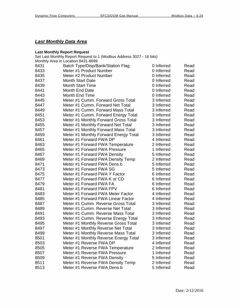
Dynamic Flow Computers SFC332GM Gas Manual Modbus Data – 4-24
Date: 2/12/2016
Last Monthly Data Area
Last Monthly Report Request Set Last Monthly Report Request to 1 (Modbus Address 3027 - 16 bits) Monthly Area in Location 8431-8699
8431 Batch Type/Disp/Bank/Station Flag 0 Inferred Read 8433 Meter #1 Product Number 0 Inferred Read 8435 Meter #2 Product Number 0 Inferred Read 8437 Month Start Date 0 Inferred Read 8439 Month Start Time 0 Inferred Read 8441 Month End Date 0 Inferred Read 8443 Month End Time 0 Inferred Read 8445 Meter #1 Cumm. Forward Gross Total 3 Inferred Read 8447 Meter #1 Cumm. Forward Net Total 3 Inferred Read 8449 Meter #1 Cumm. Forward Mass Total 3 Inferred Read 8451 Meter #1 Cumm. Forward Energy Total 3 Inferred Read 8453 Meter #1 Monthly Forward Gross Total 3 Inferred Read 8455 Meter #1 Monthly Forward Net Total 3 Inferred Read 8457 Meter #1 Monthly Forward Mass Total 3 Inferred Read 8459 Meter #1 Monthly Forward Energy Total 3 Inferred Read 8461 Meter #1 Forward FWA DP 4 Inferred Read 8463 Meter #1 Forward FWA Temperature 2 Inferred Read 8465 Meter #1 Forward FWA Pressure 1 Inferred Read 8467 Meter #1 Forward FWA Density 5 Inferred Read 8469 Meter #1 Forward FWA Density Temp 2 Inferred Read 8471 Meter #1 Forward FWA Dens.b 5 Inferred Read 8473 Meter #1 Forward FWA SG 5 Inferred Read 8475 Meter #1 Forward FWA Y Factor 6 Inferred Read 8477 Meter #1 Forward FWA K or CD 6 Inferred Read 8479 Meter #1 Forward FWA FA 6 Inferred Read 8481 Meter #1 Forward FWA FPV 6 Inferred Read 8483 Meter #1 Forward FWA Meter Factor 4 Inferred Read 8485 Meter #1 Forward FWA Linear Factor 4 Inferred Read 8487 Meter #1 Cumm. Reverse Gross Total 3 Inferred Read 8489 Meter #1 Cumm. Reverse Net Total 3 Inferred Read 8491 Meter #1 Cumm. Reverse Mass Total 3 Inferred Read 8493 Meter #1 Cumm. Reverse Energy Total 3 Inferred Read 8495 Meter #1 Monthly Reverse Gross Total 3 Inferred Read 8497 Meter #1 Monthly Reverse Net Total 3 Inferred Read 8499 Meter #1 Monthly Reverse Mass Total 3 Inferred Read 8501 Meter #1 Monthly Reverse Energy Total 3 Inferred Read 8503 Meter #1 Reverse FWA DP 4 Inferred Read 8505 Meter #1 Reverse FWA Temperature 2 Inferred Read 8507 Meter #1 Reverse FWA Pressure 1 Inferred Read 8509 Meter #1 Reverse FWA Density 5 Inferred Read 8511 Meter #1 Reverse FWA Density Temp 2 Inferred Read 8513 Meter #1 Reverse FWA Dens.b 5 Inferred Read

Dynamic Flow Computers SFC332GM Gas Manual Modbus Data – 4-25
Date: 2/12/2016
8515 Meter #1 Reverse FWA SG 5 Inferred Read 8517 Meter #1 Reverse FWA Y Factor 6 Inferred Read 8519 Meter #1 Reverse FWA K or CD 6 Inferred Read 8521 Meter #1 Reverse FWA FA 6 Inferred Read 8523 Meter #1 Reverse FWA FPV 6 Inferred Read 8525 Meter #1 Reverse FWA Meter Factor 4 Inferred Read 8527 Meter #1 Reverse FWA Linear Factor 4 Inferred Read 8529-8531 Meter #1 ID 8 Chars. Read 8533 Meter #1 Pipe ID 4 Inferred Read 8585 Meter #1 Orifice ID 4 Inferred Read 8537 Meter #1 Density Correction Factor 5 Inferred Read 8539 Meter #1 Density Dry Air 5 Inferred Read 8541 Meter #1 Calculation Type 0 Inferred Read 8543 Meter #1 Heating Value 4 Inferred Read 8545 Meter #1 K Factor 3 Inferred Read 8547-8553 Spare 8555 Meter #2 Cumm. Forward Gross Total 3 Inferred Read 8557 Meter #2 Cumm. Forward Net Total 3 Inferred Read 8559 Meter #2 Cumm. Forward Mass Total 3 Inferred Read 8561 Meter #2 Cumm. Forward Energy Total 3 Inferred Read 8563 Meter #2 Monthly Forward Gross Total 3 Inferred Read 8565 Meter #2 Monthly Forward Net Total 3 Inferred Read 8567 Meter #2 Monthly Forward Mass Total 3 Inferred Read 8569 Meter #2 Monthly Forward Energy Total 3 Inferred Read 8571 Meter #2 Forward FWA DP 4 Inferred Read 8573 Meter #2 Forward FWA Temperature 2 Inferred Read 8575 Meter #2 Forward FWA Pressure 1 Inferred Read 8577 Meter #2 Forward FWA Density 5 Inferred Read 8579 Meter #2 Forward FWA Density Temp 2 Inferred Read 8581 Meter #2 Forward FWA Density.b 5 Inferred Read 8583 Meter #2 Forward FWA SG 5 Inferred Read 8585 Meter #2 Forward FWA Y Factor 6 Inferred Read 8587 Meter #2 Forward FWA K or CD 6 Inferred Read 8589 Meter #2 Forward FWA FA 6 Inferred Read 8591 Meter #2 Forward FWA FPV 6 Inferred Read 8593 Meter #2 Forward FWA Meter Factor 4 Inferred Read 8595 Meter #2 Forward FWA Linear Factor 4 Inferred Read 8597 Meter #2 Cumm. Reverse Gross Total 3 Inferred Read 8599 Meter #2 Cumm. Reverse Net Total 3 Inferred Read 8601 Meter #2 Cumm. Reverse Mass Total 3 Inferred Read 8603 Meter #2 Cumm. Reverse Energy Total 3 Inferred Read 8605 Meter #2 Monthly Reverse Gross Total 3 Inferred Read 8607 Meter #2 Monthly Reverse Net Total 3 Inferred Read 8609 Meter #2 Monthly Reverse Mass Total 3 Inferred Read 8611 Meter #2 Monthly Reverse Energy Total 3 Inferred Read 8613 Meter #2 Reverse FWA DP 4 Inferred Read

Dynamic Flow Computers SFC332GM Gas Manual Modbus Data – 4-26
Date: 2/12/2016
8615 Meter #2 Reverse FWA Temperature 2 Inferred Read 8617 Meter #2 Reverse FWA Pressure 1 Inferred Read 8619 Meter #2 Reverse FWA Density 5 Inferred Read 8621 Meter #2 Reverse FWA Density Temp 2 Inferred Read 8623 Meter #2 Reverse FWA Density.b 5 Inferred Read 8625 Meter #2 Reverse FWA SG 5 Inferred Read 8627 Meter #2 Reverse FWA Y Factor 6 Inferred Read 8629 Meter #2 Reverse FWA K or CD 6 Inferred Read 8631 Meter #2 Reverse FWA FA 6 Inferred Read 8633 Meter #2 Reverse FWA FPV 6 Inferred Read 8635 Meter #2 Reverse FWA Meter Factor 4 Inferred Read 8637 Meter #2 Reverse FWA Linear Factor 4 Inferred Read 8639-8641 Meter #2 ID 8 Chars. Read 8643 Meter # Pipe ID 4 Inferred Read 8645 Meter #2 Orifice ID 4 Inferred Read 8647 Meter #2 Density Correction Factor 5 Inferred Read 8649 Meter #2 Density Dry Air 5 Inferred Read 8651 Meter #2 Calculation Type 0 Inferred Read 8653 Meter #2 Heating Value 4 Inferred Read 8655 Meter #2 K Factor 3 Inferred Read 8657-8667 Spare 8669 Station Cumm. Forward Gross Total 3 Inferred Read 8671 Station Cumm. Forward Net Total 3 Inferred Read 8673 Station Cumm. Forward Mass Total 3 Inferred Read 8675 Station Cumm. Forward Energy Total 3 Inferred Read 8677 Station Monthly Forward Gross Total 3 Inferred Read 8679 Station Monthly Forward Net Total 3 Inferred Read 8681 Station Monthly Forward Mass Total 3 Inferred Read 8683 Station Monthly Forward Energy Total 3 Inferred Read 8685 Station Cumm. Reverse Gross Total 3 Inferred Read 8687 Station Cumm. Reverse Net Total 3 Inferred Read 8689 Station Cumm. Reverse Mass Total 3 Inferred Read 8691 Station Cumm. Reverse Energy Total 3 Inferred Read 8693 Station Monthly Reverse Gross Total 3 Inferred Read 8695 Station Monthly Reverse Net Total 3 Inferred Read 8697 Station Monthly Reverse Mass Total 3 Inferred Read 8699 Station Monthly Reverse Energy Total 3 Inferred Read Last Monthly Data Area End
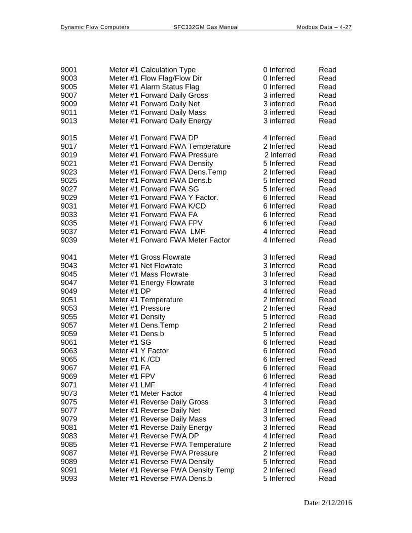
Dynamic Flow Computers SFC332GM Gas Manual Modbus Data – 4-27
Date: 2/12/2016
9001 Meter #1 Calculation Type 0 Inferred Read 9003 Meter #1 Flow Flag/Flow Dir 0 Inferred Read 9005 Meter #1 Alarm Status Flag 0 Inferred Read 9007 Meter #1 Forward Daily Gross 3 inferred Read 9009 Meter #1 Forward Daily Net 3 inferred Read 9011 Meter #1 Forward Daily Mass 3 inferred Read 9013 Meter #1 Forward Daily Energy 3 inferred Read 9015 Meter #1 Forward FWA DP 4 Inferred Read 9017 Meter #1 Forward FWA Temperature 2 Inferred Read 9019 Meter #1 Forward FWA Pressure 2 lnferred Read 9021 Meter #1 Forward FWA Density 5 Inferred Read 9023 Meter #1 Forward FWA Dens.Temp 2 Inferred Read 9025 Meter #1 Forward FWA Dens.b 5 Inferred Read 9027 Meter #1 Forward FWA SG 5 Inferred Read 9029 Meter #1 Forward FWA Y Factor. 6 Inferred Read 9031 Meter #1 Forward FWA K/CD 6 Inferred Read 9033 Meter #1 Forward FWA FA 6 Inferred Read 9035 Meter #1 Forward FWA FPV 6 Inferred Read 9037 Meter #1 Forward FWA LMF 4 Inferred Read 9039 Meter #1 Forward FWA Meter Factor 4 Inferred Read 9041 Meter #1 Gross Flowrate 3 Inferred Read 9043 Meter #1 Net Flowrate 3 Inferred Read 9045 Meter #1 Mass Flowrate 3 Inferred Read 9047 Meter #1 Energy Flowrate 3 Inferred Read 9049 Meter #1 DP 4 Inferred Read 9051 Meter #1 Temperature 2 Inferred Read 9053 Meter #1 Pressure 2 Inferred Read 9055 Meter #1 Density 5 Inferred Read 9057 Meter #1 Dens.Temp 2 Inferred Read 9059 Meter #1 Dens.b 5 Inferred Read 9061 Meter #1 SG 6 Inferred Read 9063 Meter #1 Y Factor 6 Inferred Read 9065 Meter #1 K /CD 6 Inferred Read 9067 Meter #1 FA 6 Inferred Read 9069 Meter #1 FPV 6 Inferred Read 9071 Meter #1 LMF 4 Inferred Read 9073 Meter #1 Meter Factor 4 Inferred Read 9075 Meter #1 Reverse Daily Gross 3 Inferred Read 9077 Meter #1 Reverse Daily Net 3 Inferred Read 9079 Meter #1 Reverse Daily Mass 3 Inferred Read 9081 Meter #1 Reverse Daily Energy 3 Inferred Read 9083 Meter #1 Reverse FWA DP 4 Inferred Read 9085 Meter #1 Reverse FWA Temperature 2 Inferred Read 9087 Meter #1 Reverse FWA Pressure 2 Inferred Read 9089 Meter #1 Reverse FWA Density 5 Inferred Read 9091 Meter #1 Reverse FWA Density Temp 2 Inferred Read 9093 Meter #1 Reverse FWA Dens.b 5 Inferred Read

Dynamic Flow Computers SFC332GM Gas Manual Modbus Data – 4-28
Date: 2/12/2016
9095 Meter #1 Reverse FWA SG 5 Inferred Read 9097 Meter #1 Reverse FWA Y Factor 6 Inferred Read 9099 Meter #1 Reverse FWA K/CD 6 Inferred Read 9101 Meter #1 Reverse FWA FA 6 Inferred Read 9103 Meter #1 Reverse FWA FPV 6 Inferred Read 9105 Meter #1 Reverse FWA LMF 4 Inferred Read 9107 Meter #1 Reverse FWA Meter Factor 4 Inferred Read 9109-9123 Spare 9125 Meter #1 Reverse Cum. Gross 3 Inferred Read 9127 Meter #1 Reverse Cum. Net 3 Inferred Read 9129 Meter #1 Reverse Cum. Mass 3 Inferred Read 9131 Meter #1 Reverse Cum. Energy 3 Inferred Read 9133 Meter #1 Forward Cum. Gross 3 Inferred Read 9135 Meter #1 Forward Cum. Net 3 Inferred Read 9137 Meter #1 Forward Cum. Mass 3 Inferred Read 9139 Meter #1 Forward Cum. Energy 3 Inferred Read 9141 Meter #1 Density Calc. Type 0 Inferred Read 9143-9145 Meter #1 Meter ID 8 Chars. Read 9147 Meter #1 Pipe ID 4 Inferred Read 9149 Meter #1 Orifice ID 4 Inferred Read 9151 Meter #1 Density Correction Factor 5 Inferred Read 9153 Meter #1 Density of Dry Air 5 Inferred Read 9155 Meter #1 Heating Value 4 Inferred Read 9157 Meter #1 K Factor 3 Inferred Read 9159 Curretn Date mm/dd/yy 0 Inferred Read 9161 Current Time hh/mm/ss 0 Inferred Read 9163-9201 Spare 9201 Meter #2 Calculation Type 0 Inferred Read 9203 Meter #2 Flow Flag/Flow Dir 0 Inferred Read 9205 Meter #2 Alarm Status Flag 0 Inferred Read 9207 Meter #2 Forward Daily Gross 3 inferred Read 9209 Meter #2 Forward Daily Net 3 inferred Read 9211 Meter #2 Forward Daily Mass 3 inferred Read 9213 Meter #2 Forward Daily Energy 3 inferred Read 9215 Meter #2 Forward FWA DP 4 Inferred Read 9217 Meter #2 Forward FWA Temperature 2 Inferred Read 9219 Meter #2 Forward FWA Pressure 2 Inferred Read 9221 Meter #2 Forward FWA Density 5 Inferred Read 9223 Meter #2 Forward FWA Dens.Temp 2 Inferred Read 9225 Meter #2 Forward FWA Dens.b 5 Inferred Read 9227 Meter #2 Forward FWA SG 5 Inferred Read 9229 Meter #2 Forward FWA Y Factor. 6 Inferred Read 9231 Meter #2 Forward FWA K/CD/LMF 6 Inferred Read 9233 Meter #2 Forward FWA FA 6 Inferred Read 9235 Meter #2 Forward FWA FPV 6 Inferred. Read 9237 Meter #2 Forward FWA LMF 4 Inferred Read 9239 Meter #2 Forward FWA Meter Factor 4 Inferred Read

Dynamic Flow Computers SFC332GM Gas Manual Modbus Data – 4-29
Date: 2/12/2016
9241 Meter #2 Gross Flow Rate 3 Inferred Read 9243 Meter #2 Net Flow Rate 3 Inferred Read 9245 Meter #2 Mass Flow Rate 3 Inferred Read 9247 Meter #2 Energy Flow Rate 3 Inferred Read 9249 Meter #2 DP 4 Inferred Read 9251 Meter #2 Temperature 2 Inferred Read 9253 Meter #2 Pressure 2 Inferred Read 9255 Meter #2 Density 5 Inferred Read 9257 Meter #2 Dens.Temp 2 Inferred Read 9259 Meter #2 Dens.b 5 Inferred Read 9261 Meter #2 SG 5 Inferred Read 9263 Meter #2 Y Factor 6 Inferred Read 9265 Meter #2 K/CD 6 Inferred Read 9267 Meter #2 FA 6 Inferred Read 9269 Meter #2 FPV 6 Inferred Read 9271 Meter #2 LMF 4 Inferred Read 9273 Meter #2 Meter Factor 4 Inferred Read 9275 Meter #2 Reverse Daily Gross 3 Inferred Read 9277 Meter #2 Reverse Daily Net 3 Inferred Read 9279 Meter #2 Reverse Daily Mass 3 Inferred Read 9281 Meter #2 Reverse Daily Energy 3 Inferred Read 9283 Meter #2 Reverse FWA DP 4 Inferred Read 9285 Meter #2 Reverse FWA Temperature 2 Inferred Read 9287 Meter #2 Reverse FWA Pressure 2 Inferred Read 9289 Meter #2 Reverse FWA Density 5 Inferred Read 9291 Meter #2 Reverse FWA Density Temp 2 Inferred Read 9293 Meter #2 Reverse FWA Dens.b 5 Inferred Read 9295 Meter #2 Reverse FWA SG 5 Inferred Read 9297 Meter #2 Reverse FWA Y Factor 6 Inferred Read 9299 Meter #2 Reverse FWA K/CD 6 Inferred Read 9301 Meter #2 Reverse FWA FA 6 Inferred Read 9303 Meter #2 Reverse FWA FPV 6 Inferred Read 9305 Meter #2 Reverse FWA LMF 4 Inferred Read 9307 Meter #2 Reverse FWA Meter Factor 4 Inferred Read 9309-9323 Spare 9325 Meter #2 Reverse Cum. Gross 3 Inferred Read 9327 Meter #2 Reverse Cum. Net 3 Inferred Read 9329 Meter #2 Reverse Cum. Mass 3 Inferred Read 9331 Meter #2 Reverse Cum. Energy 3 Inferred Read 9333 Meter #2 Forward Cum. Gross 3 Inferred Read 9335 Meter #2 Forward Cum. Net 3 Inferred Read 9337 Meter #2 Forward Cum. Mass 3 Inferred Read 9339 Meter #2 Forward Cum. Energy 3 Inferred Read 9341 Meter #2 Density Calc. Type 0 Inferred Read 9343-9345 Meter #2 Meter ID 8 Chars. Read 9347 Meter #2 Pipe ID 4 Inferred Read 9349 Meter #2 Orifice ID 4 Inferred Read 9351 Meter #2 Density Correction Factor 5 Inferred Read 9353 Meter #2 Density of Dry Air 5 Inferred Read 9355 Meter #2 Heating Value 4 Inferred Read

Dynamic Flow Computers SFC332GM Gas Manual Modbus Data – 4-30
Date: 2/12/2016
9357 Meter #2 K Factor 3 Inferred Read 9359-9367 Spare 9369-9399 Spare 9401 Spare #1 Data Spare Reso. Read 9403 Spare #2 Data Spare Reso. Read