MicroMVG OPERATORS MANUAL - Dynamic...
145
Date: 8/13/2013 MicroMVG OPERATORS MANUAL Flow Computer Gas Version5 12603 Southwest Freeway, Suite 320 Stafford, Texas 77477 USA (281) 565-1118 Fax (281) 565-1119
-
Upload
nguyenduong -
Category
Documents
-
view
227 -
download
1
Transcript of MicroMVG OPERATORS MANUAL - Dynamic...

Date: 8/13/2013
MicroMVG
OPERATORS MANUAL Flow Computer
Gas Version5
12603 Southwest Freeway, Suite 320
Stafford, Texas 77477 USA
(281) 565-1118
Fax (281) 565-1119

Date: 8/13/2013
WARRANTY
Dynamic Flow Computers warrants to the owner of the Smart Flow Computer that the
product delivered will be free from defects in material and workmanship for one (1) year
following the date of purchase.
This warranty does not cover the product if it is damaged in the process of being installed
or damaged by abuse, accident, misuse, neglect, alteration, repair, disaster, or improper
testing.
If the product is found otherwise defective, Dynamic Flow Computers will replace or
repair the product at no charge, provided that you deliver the product along with a return
material authorization (RMA) number from Dynamic Flow Computers.
Dynamic Flow Computers will not assume any shipping charge or be responsible for
product damage due to improper shipping.
THE ABOVE WARRANTY IS IN LIEU OF ANY OTHER WARRANTY EXPRESS
IMPLIED OR STATUTORY. BUT NOT LIMITED TO ANY WARRANTY OF
MERCHANTABILITY, FITNESS FOR PARTICULAR PURPOSE, OR ANY
WARRANTY ARISING OUT OF ANY PROPOSAL, SPECIFICATION, OR SAMPLE.
LIMITATION OF LIABILITY:
DYNAMIC FLOW COMPUTERS SHALL HAVE NO LIABILITY FOR ANY
INDIRECT OR SPECULATIVE DAMAGES (INCLUDING, WITHOUT LIMITING
THE FOREGOING, CONSEQUENTIAL, INCIDENTAL AND SPECIAL DAMAGES)
ARISING FROM THE USE OF, OR INABILITY TO USE THIS PRODUCT.
WHETHER ARISING OUT OF CONTRACT, OR UNDER ANY WARRANTY,
IRRESPECTIVE OF WHETHER DFM HAS ADVANCED NOTICE OF THE
POSSIBILITY OF ANY SUCH DAMAGE INCLUDING, BUT NOT LIMITED TO
LOSS OF USE, BUSINESS INTERRUPTION, AND LOSS OF PROFITS.
NOTWITHSTANDING THE FOREGOING, DFM’S TOTAL LIABILITY FOR ALL
CLAIMS UNDER THIS AGREEMENT SHALL NOT EXCEED THE PRICE PAID
FOR THE PRODUCT. THESE LIMITATIONS ON POTENTIAL LIABILITY WERE
AN ESSENTIAL ELEMENT IN SETTING THE PRODUCT PRICE. DFM NEITHER
ASSUMES NOR AUTHORIZES ANYONE TO ASSUME FOR IT ANY OTHER
LIABILITIES

Date: 8/13/2013
CHAPTER 1: QUICK START.................................................................................................................... 1-1 Introduction: ............................................................................................................................................ 1-1 Quick Start Up ......................................................................................................................................... 1-2 Technical Data ......................................................................................................................................... 1-4 Parts List .................................................................................................................................................. 1-5
System Minimum Requirements ......................................................................................................... 1-7 What is a configuration file? ................................................................................................................... 1-8 Downloading a configuration file to the flow computer. ......................................................................... 1-8 What is an Image File? ............................................................................................................................ 1-9 How to download an Image File .............................................................................................................. 1-9 How to force a board into download mode............................................................................................ 1-10 Website - DFM Configuration Software ............................................................................................... 1-11 Website – Image File (Firmware) .......................................................................................................... 1-12 Getting acquainted with the flow computer wiring: .............................................................................. 1-13
Back terminal wiring: ........................................................................................................................ 1-13 Back Panel Jumper ............................................................................................................................ 1-14
INPUT/OUTPUT: Assigning and Ranging Inputs ............................................................................... 1-15 Input/Output Assignment .................................................................................................................. 1-15 How to assign a transmitter to an I/O point through window program: ............................................ 1-15 How to assign a transmitter to an I/O point through DOS program: ................................................. 1-15 Ranging the Transmitter Inputs: ........................................................................................................ 1-16
WIRING: ............................................................................................................................................... 1-17 Wiring the analog inputs: .................................................................................................................. 1-17 RTD ................................................................................................................................................... 1-18 Wiring analog output: ........................................................................................................................ 1-19 Turbine input wiring .......................................................................................................................... 1-20 Turbine input wiring – Using Daniel 1817 Preamp ........................................................................... 1-21 Turbine input wiring – Using Daniel 1818 Preamp ........................................................................... 1-22 RS-232 connection: ........................................................................................................................... 1-23 Printer Connection: ............................................................................................................................ 1-24 RS-485: .............................................................................................................................................. 1-25 Wiring of status inputs: ..................................................................................................................... 1-26 Wiring of switch/pulse outputs: ......................................................................................................... 1-27 Switch Output to Relay Wiring Diagram .......................................................................................... 1-28 Density input wiring: ......................................................................................................................... 1-29
CALIBRATION Through DOS Program .............................................................................................. 1-30 Analog Input 4-20mA or 1-5 volt signal .......................................................................................... 1-30 RTD calibration: ................................................................................................................................ 1-31 Calibration of analog output: ............................................................................................................. 1-32 Multi-Variable Transmitters (Model 205) – DP and Pressure ........................................................... 1-33 Multi-Variable Transmitters (Model 205)- RTD ............................................................................... 1-34
Verifying digital inputs and outputs ...................................................................................................... 1-35 CHAPTER 2: Data Entry ............................................................................................................................ 2-1
Introduction to the MicroMVG Software ................................................................................................ 2-1 Configuration File through DOS Program............................................................................................... 2-1
About ................................................................................................................................................... 2-1 File ........................................................................................................................................................... 2-2
Open a File .......................................................................................................................................... 2-2 Open a New File .................................................................................................................................. 2-2 Delete a File ......................................................................................................................................... 2-2 Load File.............................................................................................................................................. 2-2 View File ............................................................................................................................................. 2-2 Save As ................................................................................................................................................ 2-3 Save ..................................................................................................................................................... 2-3 Save and Exit ....................................................................................................................................... 2-3
Date: 8/13/2013
Exit ...................................................................................................................................................... 2-3 PORT ....................................................................................................................................................... 2-4
PC Communication Set Up.................................................................................................................. 2-4 Flow Computer Communication Set Up ............................................................................................. 2-5 Dial ...................................................................................................................................................... 2-7 Phone Book ......................................................................................................................................... 2-7 Phone Book Edit .................................................................................................................................. 2-7 Modem Setup ...................................................................................................................................... 2-7 Hang-up Phone .................................................................................................................................... 2-7
DIAG ....................................................................................................................................................... 2-8 Read Single Flow Computer Communication Setup ........................................................................... 2-8 Diagnostic Data ................................................................................................................................... 2-8 Micro MV Gas Flow Computer Configuration Diagram .................................................................... 2-9
METER ................................................................................................................................................. 2-10 Set Up ................................................................................................................................................ 2-10 Meter Data ......................................................................................................................................... 2-11 Linear Factor ..................................................................................................................................... 2-16 Other Parameters ............................................................................................................................... 2-17 Date and Time ................................................................................................................................... 2-19 Parameter Overrides .......................................................................................................................... 2-19 Security Code .................................................................................................................................... 2-20
INPUT/OUTPUT .................................................................................................................................. 2-21 Transducer Input Assignment ............................................................................................................ 2-21 Transducer Tag ID ............................................................................................................................. 2-22 Calibration Mode ............................................................................................................................... 2-23 Calibration ......................................................................................................................................... 2-23 Status Input /Switch Output Assignment ........................................................................................... 2-24 Switch Output Assignment ................................................................................................................ 2-24 Analog Output Assignment ............................................................................................................... 2-25 Remote Control Analog Output Setpoint........................................................................................... 2-25 Micro MV Gas Flow Computer Display Assignment ....................................................................... 2-26 Modbus Shift ..................................................................................................................................... 2-27 Modbus Shift – Floating Point ........................................................................................................... 2-27
REPORTS ............................................................................................................................................. 2-32 Current Data - Snapshot Totalizer Updates ....................................................................................... 2-32 Previous Hourly Data ........................................................................................................................ 2-32 Previous Daily Data ........................................................................................................................... 2-32 Previous Month Data ......................................................................................................................... 2-32 Previous Alarm Data ......................................................................................................................... 2-32 Audit Trail Report ............................................................................................................................. 2-33 Build User Report .............................................................................................................................. 2-34 View User Report .............................................................................................................................. 2-34 Formatted Ticket Report .................................................................................................................... 2-34 Ticket Report ..................................................................................................................................... 2-34 Auto Data Retrieval ........................................................................................................................... 2-34
PRINT ................................................................................................................................................... 2-35 Print "Help" File ................................................................................................................................ 2-35 Print Modbus Registers ..................................................................................................................... 2-35 Print Calibration Data ........................................................................................................................ 2-35 Print Files .......................................................................................................................................... 2-35
CHAPTER 3: Data Entry ............................................................................................................................ 3-1 MAIN MENU .......................................................................................................................................... 3-2
Security Code ...................................................................................................................................... 3-2 Calibrate /1=M.Var.............................................................................................................................. 3-2 Enable Calibrate Mode ........................................................................................................................ 3-3 Calibrate Analog Input, RTD .............................................................................................................. 3-3

Date: 8/13/2013
Calibrate Analog Output ...................................................................................................................... 3-4 Calibrate Multivariable ........................................................................................................................ 3-5 Override Meter No. ............................................................................................................................. 3-7 Date/Time ............................................................................................................................................ 3-7 Configuration ....................................................................................................................................... 3-9 Configue Meter .................................................................................................................................... 3-9 Flow Equation Type (0-3) ................................................................................................................... 3-9 AGA3/New AGA3/Venturi ............................................................................................................... 3-10 AGA7 ................................................................................................................................................ 3-11 Configure I/O .................................................................................................................................... 3-11 Analog Output ................................................................................................................................... 3-12 Meter I/O ........................................................................................................................................... 3-13 Status Input /Switch Output Assignment ........................................................................................... 3-14 Switch Output Assignment ................................................................................................................ 3-14 Assignments - Pulse Outputs ............................................................................................................. 3-15 Flow Computer Display Assignment ................................................................................................. 3-16 Pulse Output ...................................................................................................................................... 3-17 Others ................................................................................................................................................ 3-17
CHAPTER 4: FLOW EQUATIONS ........................................................................................................... 4-1 Common Terms ....................................................................................................................................... 4-1 AGA3 ...................................................................................................................................................... 4-2 API 14.3................................................................................................................................................... 4-3 AGA 7 ..................................................................................................................................................... 4-4 Venturi ..................................................................................................................................................... 4-5 DENSITY EQUATIONS ........................................................................................................................ 4-6
Sarasota Density GM/CC .................................................................................................................... 4-6 UGC Density GM/CC ......................................................................................................................... 4-6 Solartron Density GM/CC ................................................................................................................... 4-7 AGA8 Gross Method 1 ........................................................................................................................ 4-8 AGA8 Gross Method 2 ........................................................................................................................ 4-8 AGA8 Detail Method .......................................................................................................................... 4-8
CHAPTER 5: MODBUS DATA ................................................................................................................. 5-1 MODBUS PROTOCOL .......................................................................................................................... 5-1
TRANSMISSION MODE ................................................................................................................... 5-1 ASCII FRAMING ............................................................................................................................... 5-1 RTU FRAMING .................................................................................................................................. 5-1 FUNCTION CODE ............................................................................................................................. 5-2 ERROR CHECK ................................................................................................................................. 5-2 EXCEPTION RESPONSE .................................................................................................................. 5-2 BROADCAST COMMAND ............................................................................................................... 5-2 MODBUS EXAMPLES ...................................................................................................................... 5-3 FUNCTION CODE 03 (Read Single or Multiple Register Points) ..................................................... 5-3 ASCII MODE - Read Address 3076 ................................................................................................... 5-3
MODBUS ADDRESS TABLE – 16 BITS ............................................................................................. 5-4 Scaled Data Area ................................................................................................................................. 5-8 Modbus 16-bit Address Table Ends .................................................................................................... 5-8 Last Daily or Monthly Data Area ...................................................................................................... 5-12 NX19 Method .................................................................................................................................... 5-14 AGA 8 GROSS METHOD 1 ............................................................................................................. 5-15 AGA 8 GROSS METHOD 2 ............................................................................................................. 5-15 AGA 8 Detail Method ....................................................................................................................... 5-16 Last Hourly Data Area ....................................................................................................................... 5-21 FLOATING POINT - CURRENT DATA AREA – METER #1 ...................................................... 5-25 FLOATING POINT - CURRENT DATA AREA ............................................................................. 5-26 FLOATING POINT- CURRENT DATA AREA – METER #2 ....................................................... 5-27 FLOATING POINT- CURRENT DATA AREA – METER #2 ....................................................... 5-28

Date: 8/13/2013
FLOATING POINT – Previous Daily Data Area – Meter #1 ........................................................... 5-29 FLOATING POINT – Previous Hourly Data Area – Meter #1 ......................................................... 5-30 FLOATING POINT – Previous Daily Data Area – Prog.Var ........................................................... 5-30 FLOATING POINT – Previous Daily Data Area – Meter #2 ........................................................... 5-31 FLOATING POINT – Previous Hourly Data Area _Meter #2 .......................................................... 5-32 FLOATING POINT – (701) Previous Daily Data Area – Meter #1 ................................................. 5-33 FLOATING POINT – (702) Previous Daily Data Area – Meter #2 ................................................. 5-33 FLOATING POINT – (703) Previous Daily Data Area – Meter #1 ................................................. 5-34 FLOATING POINT – (704) Previous Hourly Data Area – Meter #1 ............................................... 5-34 FLOATING POINT – (705) Previous Daily Data Area – Meter #2 ................................................ 5-35 FLOATING POINT – (706) Previous Hourly Data Area – Meter #2 ............................................... 5-35 Programmable Floating Point Variable ............................................................................................. 5-36
CHAPTER 6: Installation Drawings ........................................................................................................... 6-1 Explosion-Proof Installation Drawings ................................................................................................... 6-1 Manifold Installation Drawings ............................................................................................................... 6-4

Dynamic Flow Computers MicroMV Gas Version5 Manual Quick Start — 1-1
Date: 8/13/2013
CHAPTER 1: QUICK START
Introduction: The micro MV Gas Flow Computer was designed after careful listening to our customers in all sectors of
the oil and gas industry. It was built to address the different needs for refineries, chemical plants, gas
processing plants, offshore platforms, pipeline and transmission, remote gas wells, and storage caverns.
The focus has been to bring the different needs and requirements of these specialized industries into one
hardware platform and therefore reducing the spare parts requirements, the training process, calibration,
and overall cost of ownership. We believe the Micro MV Gas Flow Computer has delivered and met the
design intentions.
The Micro MV Gas Flow Computer combines the following features:
User Friendly
Flexible
Easy to understand and configure
Rugged
Economical to install and maintain
Accurate
We hope that your experience with the Micro MV Gas Flow Computer will be a simple pleasant
experience, not intimidating in any way.
The Micro MV Flow computer handles up to two-meter runs with bi-directional capabilities. It includes
the following mass flow equations: New API14.3, venturi,, turbine (AGA7), Ultrasonic meter.
Additionally, it can perform density calculations per these standard procedures: AGA8, NX19 for gas,, and
other tables are added constantly, call our main office for current equations
One Rosemount multi-variable digital transducers can be connected to each Micro MV flow computer for
temperature, pressure (up to 3626 PSIG), and DP (up to 830 inches H2O). Other Rosemount multi variable
transmitters can be connected to the Micro MV Gas Flow Computer via RS485 serial interface. Up to four
meter runs can be stored and calculated in a single Micro MV Gas flow computer. The 2nd
RS485 is used as
a slave or a master modbus port for data acquisition and other serial functions.
The Micro MV Gas flow Computer has a host of inputs and outputs beyond the built in rosemount Multi
Variable transmitter.
Three turbine inputs (Sine or Square wave), 70 mV peak to peak or sine wave 6 volts, or lighter on square
wave
Four additional analog inputs, or two analog inputs and one three wire RTD inputs
One analog output expandable to four
One RS-232 and two RS-485 with Modbus protocol, one serial printer output
4 status inputs or digital outputs (user configurable).
Additionally, each Micro MV Gas Flow Computer can store up to 32 days of hourly and daily data.
Optional expandable memory (Virtual Hard Drive) up to 132 Megs ; combined with our customized data
storage allows almost any type data logging task to become possible.

Dynamic Flow Computers MicroMV Gas Version5 Manual Quick Start — 1-2
Date: 8/13/2013
Quick Start Up

Dynamic Flow Computers MicroMV Gas Version5 Manual Quick Start — 1-3
Date: 8/13/2013

Dynamic Flow Computers MicroMV Gas Version5 Manual Quick Start — 1-4
Date: 8/13/2013
Technical Data
POWER
VOLTAGE RANGE 7-28 VDC
POWER CONSUMPTION 0.5 WATT
OPERATING CONDITIONS
TEMPERATURE - 40 TO 185 °F
HUMIDITY 100%
HOUSING NEMA 4X CLASS 1 DIV. 1
FEATURES
DISPLAY PLASMA 4 LINES 20 CHARACTERS BACKLIT DISPLAY WITH 4 INFRARED REFLECTIVE SENSORS
PROCESSOR 32-BIT MOTOROLA 68332 @ 16.7 MHZ
FLASH ROM 4 MBITS @ 70 NANO SECONDS
RAM 2 MBITS
FREQUENCY INPUT 3 CHANNELS CHANNELS 1 & 2 ARE SINE/SQUARE WAVE CAPABLE CHANNEL 3 IS SQUARE WAVE ONLY SQUARE WAVE RANGE 0 - 6000 HZ
SINE WAVE RANGE 0 – 1200 HZ SIGNAL > 40 mV FOR SINE WAVE SIGNAL > 3 VOLTS FOR SQUARE WAVE
ANALOG INPUT 4 INPUTS STANDARD EXPANDABLE UP TO 9 ANALOG INPUTS OR 7 WITH ADDITIONAL 3 WIRE RTD.
MULTIVARIABLE BUILT-IN ROSEMOUNT MULTIVARIABLE TRANSMITTER WITH DIRECT SPI DIGITAL CONNECTION. MAXIMUM UPDATE SPEED ONCE EVERY 109 MILLISECONDS.
ANALOG OUTPUT ONE (1) OPTICALLY ISOLATED 16 BITS EXPANDABLE TO FOUR (4)
DIGITAL I/O 4 DIGITAL INPUTS OR OUTPUTS. DIGITAL OUTPUTS HAVE 0.25 AMPS RATING.
SERIAL 2 RS485 @ 19200 BAUDS VARIABLE 1 RS232 @ 9600 BAUDS VARIABLE 1 PRINTER OUTPUT
COMMUNICATION PROTOCOL MODBUS

Dynamic Flow Computers MicroMV Gas Version5 Manual Quick Start — 1-5
Date: 8/13/2013
Parts List

Dynamic Flow Computers MicroMV Gas Version5 Manual Quick Start — 1-6
Date: 8/13/2013
Micro MV Flow Computer: Dimensions

Dynamic Flow Computers MicroMV Gas Version5 Manual Quick Start — 1-7
Date: 8/13/2013
Window Software Minimum Requirements:
Please make sure your computer has the minimum requirements to install Dynamic’s Dynacom software.
System Minimum Requirements
In order to install this software product the following requirements must be met:
Windows Operating System (Win95, Win98, Win98SE, win2000, WinNT, WinXP, Vista)
For a Windows NT machine: Service Pack 3 or later. (Service Pack 5 Update is Included in the
Installation Disk)
Internet Explorer 5 or later. (Internet Update is Included in the Installation Disk)
For Windows NT, 2000, XP or Vista: Administrator level access to create an ODBC system DNS.
Minimum disk space available: 16 MB.
1 Serial Communication Port
If your computer meets these requirements, you can run the setup file downloaded from our website
Dynamic Flow Computers MicroMV Gas Version5 Manual Quick Start — 1-8
Date: 8/13/2013
What is a configuration file? The configuration file is an archive that contains the data used by the flow computer to determine calculation settings (Pipe ID, Flow Equation, Meter ID, etc.) and input/output assignments.
Downloading a configuration file to the flow computer.
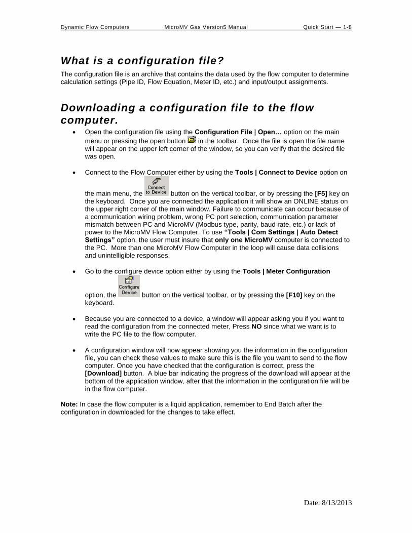
Open the configuration file using the Configuration File | Open… option on the main
menu or pressing the open button in the toolbar. Once the file is open the file name will appear on the upper left corner of the window, so you can verify that the desired file was open.
Connect to the Flow Computer either by using the Tools | Connect to Device option on
the main menu, the button on the vertical toolbar, or by pressing the [F5] key on the keyboard. Once you are connected the application it will show an ONLINE status on the upper right corner of the main window. Failure to communicate can occur because of a communication wiring problem, wrong PC port selection, communication parameter mismatch between PC and MicroMV (Modbus type, parity, baud rate, etc.) or lack of power to the MicroMV Flow Computer. To use “Tools | Com Settings | Auto Detect Settings” option, the user must insure that only one MicroMV computer is connected to the PC. More than one MicroMV Flow Computer in the loop will cause data collisions and unintelligible responses.
Go to the configure device option either by using the Tools | Meter Configuration
option, the button on the vertical toolbar, or by pressing the [F10] key on the keyboard.
Because you are connected to a device, a window will appear asking you if you want to read the configuration from the connected meter, Press NO since what we want is to write the PC file to the flow computer.
A configuration window will now appear showing you the information in the configuration file, you can check these values to make sure this is the file you want to send to the flow computer. Once you have checked that the configuration is correct, press the [Download] button. A blue bar indicating the progress of the download will appear at the bottom of the application window, after that the information in the configuration file will be in the flow computer.
Note: In case the flow computer is a liquid application, remember to End Batch after the configuration in downloaded for the changes to take effect.

Dynamic Flow Computers MicroMV Gas Version5 Manual Quick Start — 1-9
Date: 8/13/2013
What is an Image File? An image file is an EPROM code for a certain purpose (liquid, gas, prover, etc.) The image file is only done when an application upgrade is needed. When an image file is downloaded to the flow computer, all the information in the computer is lost (configuration and historical data), so make sure to retrieve all the important information before changing the image file.
How to download an Image File Download an image file through RS232 port only.
To Download an Image File to the Flow Computer select the Tools | Download Program
option form the main menu or press the button in the toolbar.
A small dialog will appear asking for the file name of the image file (Image file have the extension .img). Type it in or use the Browse button to locate it.
Once the file name is in place press Download.
If a retry message of small dialog appears, try to use “Tools | Com Settings | Auto Detect Settings” option, the user must insure that only one MicroMV computer is connected to the PC. More than one MicroMV Flow Computer in the loop will cause data collisions and unintelligible responses. Failure to communicate can occur because of a communication wiring problem, wrong PC port selection, communication parameter mismatch between PC and MicroMV (Modbus type, parity, baud rate, etc.) or lack of power to the MicroMV Flow Computer. After the device is detected, then you can follow steps described above.
Warning messages will remind you that this action will erase ALL the information in the flow computer. The download task will take about 7 minutes to be completed. Once the image file is in place, the flow computer is ready to be configured (enter calculation parameters and I/O assignments).

Dynamic Flow Computers MicroMV Gas Version5 Manual Quick Start — 1-10
Date: 8/13/2013
How to force a board into download mode First try to recycle the power and reload the image if the error message is displayed while downloading a new image file. Download an image file only through RS-232 port. Contact technical support for old boards
loaded with downloader v1. Forcing download mode could be required if a wrong type of application image was loaded or other issues. Call our main office for more information
Steps to force the board into download mode. (1) Remove Power (2) Put a jumper on P6 as shown below.
(3) Power up the board (4) Board is in download mode (5) Download image (6) Remove power and jumper on P6 after a new image is loaded (7) Board is ready

Dynamic Flow Computers MicroMV Gas Version5 Manual Quick Start — 1-11
Date: 8/13/2013
Website - DFM Configuration Software
Step 1. Go to our website WWW.DYNAMICFLOWCOMPUTERS.COM
Step 2. Click on the Software link located on the left hand side of the web page. You will be presented
with two options: Windows software and DOS software.
First look for your application under Windows, if you don’t see your application listed
here it means it only has DOS software.
Step 3. Select either Windows or
DOS software based on Step 2.
Step 4. On the new screen
presented to you click on the
application that you are trying to
download. Once you hit the link it
will ask you if you want to run or
save the file in you computer.
Select SAVE. (See illustration 1)
Step 5. The file will start to
transfer to your computer. The
download time depends on your
Internet connection speed and
the type of application that being
downloaded.
Step 6. When the download if
finish. Press the OPEN button to
start the setup process. (See
Illustration)
Step 7. Follow the steps in the
application setup.
Dynamic Flow Computers MicroMV Gas Version5 Manual Quick Start — 1-12
Date: 8/13/2013
Website – Image File (Firmware) Check the version number of image file. The image file is only done when an application upgrade is needed.
Step 1. Go to our website WWW.DYNAMICFLOWCOMPUTERS.COM
Step 2. Click on the Software link located on the left hand side of the web page, then you select
Firmware option. All our image files are available for download. Only EEPROM based models like the
SFC will need actual EEPROMS to be shipped out to you.
Step 3. On the new screen presented to you click on the application that you are
trying to download. Once you hit the link it will ask you the location and file name to
be saved.
Step 4. The file will start to transfer to your computer. The download time depends
on your Internet connection speed and the type of application that being
downloaded.
Step 5. After the download is finished, follow the steps in the image downloading
setup.

Dynamic Flow Computers MicroMV Gas Version5 Manual Quick Start — 1-13
Date: 8/13/2013
Getting acquainted with the flow computer wiring:
Back terminal wiring: The back terminal wiring indicates the overall positions of the terminal plugs and their functions. Though
the back panel’s jumpers are also shown, refer to the next drawing, “Back Panel Jumpers”, for information
on their settings and functions.
The MicroMV receives its power via the .top two pins on Terminal P1, on the left of the board. Also on
Terminal P1 from top to bottom are inputs to the four serial connections
To the right (P4), from top to bottom, are two turbine inputs, density frequency input, and switch/status
inputs and output.
Terminal P3, at the lower bottom, handles analog inputs and outputs. These are, in order from right to left,
analog output one, analog input 1 & 2, RTD excitation, analog 3 & 4 or RTD, analog input return. Analog
3&4 can be used as RTD input 1,but the jumper for the RTD excitation has to be installed, and the flow
computer has to be configured for RTD input.

Dynamic Flow Computers MicroMV Gas Version5 Manual Quick Start — 1-14
Date: 8/13/2013
Back Panel Jumper In this illustration, a jumper is “ON” when the jumper block is used to connect the jumper’s to prongs. “OFF” means the jumper block is completely removed or attached to only one of the two prongs.
4 analog outputs
9 analog inputs

Dynamic Flow Computers MicroMV Gas Version5 Manual Quick Start — 1-15
Date: 8/13/2013
INPUT/OUTPUT: Assigning and Ranging Inputs
Input/Output Assignment We will now configure your Micro MV Gas Flow Computer’s inputs and outputs. The flow computer
allows the user to configure the inputs and outputs. The flow computer will not use the unassigned inputs.
How to assign a transmitter to an I/O point through window program:
1 Click “Configure Device”, configuration menu is prompted
2 On configuration menu, click “Input Assignment”
3 Enter assignments for DP, temperature, pressure, density and spare inputs.
4 Assignment (1-n). Assignments 1-4 are analog inputs attached
to terminal of the back panel. These inputs accept 4-20mA or 1-5
volts input and are suitable for temperature, pressure, density, or spare inputs. An assignment
5 is strictly RTD (temperature) input only for the meter, densitometer or spare. Assignment 7
indicates a density frequency input; it is assigned automatically once you choose live density
frequency input in the setup menu at density type Assignment 10 (module 1) is for
Rosemount multi-variable module only. DP, pressure, and temperature for the meter can be
assigned. When a frequency type primary element is hooked to the flow computer, the Multi
Variable pressure and temperature can be used and the DP becomes a spare input that could
be assigned for strainer differential.
How to assign a transmitter to an I/O point through DOS program: Before beginning the procedure of assigning inputs and outputs, it is advisable to set up the meter (Meter
| Set Up). This is because certain parameters on the Transducer Input Assignment page
change (or may not appear, etc.) based on Meter | Set Up.
(Note: This menu scrolls further down the screen for entering 4-20 ma )
1 Use your arrow keys to scroll to menu item I/O (between Meter and Report). Its first
entry is Transducer Input Assignment. Press ENTER.
2. Use the down/up arrow keys to scroll through this menu. The first four parameters are not
used. Spare inputs are inputs that the flow computer will read and display in the diagnostic
data but are not used in the calculations. Spare inputs high and low limit alarms are
documented in the historical alarm report.
3. Assignment (1-n). Assignments 1-4 are analog inputs attached to terminal of the back
panel. These inputs accept 4-20mA or 1-5 volts input and are suitable for temperature,
pressure, density, or spare inputs. Assignment 5 is strictly RTD (temperature) input only for
the meter, densitometer or spare. Assignment 7 indicates a density frequency input; it is
assigned automatically once you choose live density frequency input in the setup menu at
density type selection (and it can only be assigned via Meter | Set Up | Density #n,
where n = 1 to 5). Assignment 10 (module 1) is for Rosemount multi-variable module only.
DP, pressure, and temperature for the meter can be assigned. When a frequency type primary
element is hooked to the flow computer, the Multi Variable pressure and temperature can be
used and the DP becomes a spare input that could be assigned for strainer differential.

Dynamic Flow Computers MicroMV Gas Version5 Manual Quick Start — 1-16
Date: 8/13/2013
Ranging the Transmitter Inputs:
1. Enter the range values: after assigning the inputs scroll down the transducer inputs
assignment menu to scale the 4-20mA. Enter the value at @4mA and @20mA. Enter both
values similar to the way the transmitter is ranged. 1-5 volt is equivalent to 4-20mA. Enter
the 1 volt value at the 4mA, and 5 volt value at 20mA. When the Multi Variable is used the 4-
20 ma scale has no effect on anything and does not need to be configured for that input. The
reason is simply that the flow computer gets the data via digital communication from the
transmitter in engineering units, and therefore a scale is not needed. Normal pressure range is
0-3626, temperature –40 to 1200, DP –250 to 250, or -830 to 830 inches of water.
2. Enter the high and low limits: high limits and low limits are simply the alarm points in
which you would like the flow computer to flag as an alarm condition. Enter these values
with respect to the upper and lower range conditions. Try to avoid creating alarm log when
conditions are normal. For example: If the line condition for the pressure is between 0 to 500
PSIG. Then you should program less than zero for low pressure alarm, and 500 or more for
high pressure alarm. High limits are also used in the SCALE for the Modbus variables. The
high limit is equal to 32767 or 4095. The low limit is not used for calculating the scale. The
scale starts at zero to wherever the high limit value.
3. Set up the fail code: Maintenance and Failure Code values tell the flow computer
to use a default value in the event the transmitter fails. The default value is stored in
Maintenance. There are three outcomes: the transmitter value is always used, no matter
what (Failure Code = 0); the Maintenance value is always used, no matter what
(Failure Code = 1); and the Maintenance value is used only when the transmitter’s
value indicates that the transimtter has temporarily failed (Failure Code = 2).
RTD inputs will skip 4-20 mA assignment because RTD is a raw signal of 50 (ohms) to 156. Readings
beyond that range require a 4-20 mA signal to the flow computer or using the built in Rosemount Multi
Variable transmitter. The Rosemount Multivariable has a range of –40-1200 degrees Fahrenheit.
Density coefficients for raw frequency inputs are programmed in this menu. The menu will only show
parameters relevant to the live density selected (i.e., Solartron or UGC, etc.).

Dynamic Flow Computers MicroMV Gas Version5 Manual Quick Start — 1-17
Date: 8/13/2013
WIRING: Wiring to the flow computer is very straightforward and simple. But still it is very important to get familiar
with the wiring diagram.
Wiring the analog inputs: Typical wiring for analog inputs 1 and 2 are shown in the drawing. Analog inputs 3 and 4 are to the left of
analog 1 and 2 separated by the RTD excitation. Note that the analog input has only one common return
that is the -Ve signal of power supply powering the transmitters.
When wiring 1-5 volts, make sure to calibrate the flow computer for the 1-5 volt signal because the flow
computer calibration defaults for the 4-20 ma, which is different from the 1-5 volts. JP2 must be removed
for 1-5 volt inputs. The jumpers for analog 1-4 are in order from right to left. It is possible to remove the
first two jumpers for analog 1 & 2 in for 1-5 volts signal and have analog in 3 & 4 as 4-20 mA signal.
Signal line impedance provided by our flow computer is 250.
NOTE: The 4-20mA or 1-5 volt DOES NOT source power to the transmitters. You can use the DC power feeding the flow computer to power the 4-20mA
loops IF that power supply is FILTERED.

Dynamic Flow Computers MicroMV Gas Version5 Manual Quick Start — 1-18
Date: 8/13/2013
RTD
100 platinum must be used; a temperature range of -43F to +300F can be measured. RTD is to the left
of analog in 1&2. The RTD excitation jumper has to be installed for the RTD to function. In the figure
below, notice that the RTD requires three wire connections. Internal excitation current source generated is
in the micro AMP range.

Dynamic Flow Computers MicroMV Gas Version5 Manual Quick Start — 1-19
Date: 8/13/2013
Wiring analog output: Wiring diagram shows typical Analog output wiring. Notice that analog outputs will regulate 4-20 mA
current loops but DOES NOT source the power for it. External power is required.
ASSIGNING /RANGING THE 4-20MA ANALOG OUTPUTS :
Go to the I/O assignment main menu and click Analog Output Assignment. A selection menu
is prompted. Select the analog output number, and then enter what the 4 mA output will indicate and the
20 mA. Make sure that the 20 mA assignment value exceeds the upper range limit of what you assigned
the Analog output for, otherwise the analog output will not update beyond 20 mA.

Dynamic Flow Computers MicroMV Gas Version5 Manual Quick Start — 1-20
Date: 8/13/2013
Turbine input wiring Go to view main menu, click turbine under Wiring Drawings. Two drawings above each other will
show typical wiring for turbine meter 1 and turbine meter 2. When dual pick ups from the same turbine are
connected, use the inputs for turbine 1 for pickup 1 and turbine 2 for the second pickup coil. When
connecting sine wave directly from the pickup coil make sure the distance from the pickup coil to the flow
computer is very short–less than 50 feet with shielded cable. In the event there is presence of noise, the
distance must be shortened. When connecting sine wave signal, the JP4 jumper for meter 1 must not be
installed and JP5 jumper for meter 2 must not be installed. (JP4 and JP5 must be off when using sine
wave). On the other hand, when using square wave, the square wave signal can be sinusoidal but has to be
above 5 volts peak to peak with less than 0.4 volts offset in order for the flow computer to read it. The JP4
jumper for meter 1 must be installed and JP5 jumper for meter 2 must be installed.
Note: When connecting square wave input, the JP4 and JP5 connect the turbine return to the flow computer power return. Therefore, signal polarity is very important. Reverse polarity could result in some damage or power loss. When sine wave is used the signal polarity is usually of no significance.
The turbine input is on the top of terminal P3 The third pin down from the top is Turbine/PD input 2 plus
and below it is Turbine 2 minus. The third frequency input (fifth pin down) has the positive input and the
negative is the power input ground. If a different power supply is used to power the densitometer then the
power return for that input needs to be connected to the Micro MV power ground.

Dynamic Flow Computers MicroMV Gas Version5 Manual Quick Start — 1-21
Date: 8/13/2013
Turbine input wiring – Using Daniel 1817 Preamp

Dynamic Flow Computers MicroMV Gas Version5 Manual Quick Start — 1-22
Date: 8/13/2013
Turbine input wiring – Using Daniel 1818 Preamp

Dynamic Flow Computers MicroMV Gas Version5 Manual Quick Start — 1-23
Date: 8/13/2013
RS-232 connection: The RS-232 is located on the left terminal block. The third, fourth, fifth, and sixth pins of the RS232 below
the power input. The RS-232 RTS pin can be used for printing reports or shares common pin with the
regular RS232 port.
Note: Twisted shielded cable is required.
WARNING: When the RS-232 terminal is used with a modem, external protection on the phone line is required. Jumper DTR to DSR, RTS to CTS, and disable software handshake on the modem RS232 connection

Dynamic Flow Computers MicroMV Gas Version5 Manual Quick Start — 1-24
Date: 8/13/2013
Printer Connection:

Dynamic Flow Computers MicroMV Gas Version5 Manual Quick Start — 1-25
Date: 8/13/2013
RS-485: RS-485 wiring is shown in the wiring diagram under RS-485. Two Rs485 channels are available for
Modbus communication or as a master to other slave devices. i.e. gas G.C., external Modbus slave devices
and token passing ring. The maximum distance when 18-gauge wire is used is 4000 feet.
Note: Twisted shielded cable is required.
WARNING: When the RS-485 terminal is used, external transient protection and optical isolation is required, especially for long distance wiring.

Dynamic Flow Computers MicroMV Gas Version5 Manual Quick Start — 1-26
Date: 8/13/2013
Wiring of status inputs: There are 4 digital inputs or outputs that are user configurable. The configuration software will configure
the input to be a status input or a switch output. The fourth digital I/O is optional and can only be used if
the 2nd
RS485 is not used. The standard status input has 4 volts of noise hysteresis, with on trigger point of
5 volts and an off point of 1 Volt.

Dynamic Flow Computers MicroMV Gas Version5 Manual Quick Start — 1-27
Date: 8/13/2013
Wiring of switch/pulse outputs:
Switch one and two can be on /off or pulse type output up to 125 pulse per second. Notice that
the switch outputs are transistor type outputs (open collector type with maximum DC rating of
350 mA continuous at 24 VDC) connections 1 Status Input /switch output 1
Switch - Maximum rating: 350mA @24 volts Switch Output Range: 5-28 VDC Status Input Rating: 6-28 VDC
2 Status Input/switch output 2
3 Status Input /switch output 3
4 Status Input /switch output 4
Dynamic Flow Computers MicroMV Gas Version5 Manual Quick Start — 1-28
Date: 8/13/2013
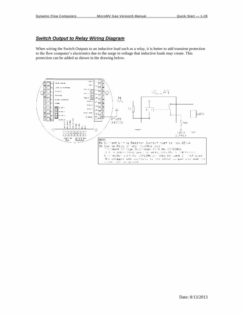
Switch Output to Relay Wiring Diagram
When wiring the Switch Outputs to an inductive load such as a relay, it is better to add transient protection
to the flow computer’s electronics due to the surge in voltage that inductive loads may create. This
protection can be added as shown in the drawing below.

Dynamic Flow Computers MicroMV Gas Version5 Manual Quick Start — 1-29
Date: 8/13/2013
Density input wiring: When using a live densitometer input with frequency signal, the signal can be brought into the MicroMV in
its raw form. The MicroMV accepts a sine wave or square with or without DC offset.
Note: When wiring the density input polarity is of significance and reverse polarity could result in some damage or power loss. When Density input is 4-20mA it should be connected as a regular 4-20mA signal to the analog input and not the density frequency input.
Dynamic Flow Computers MicroMV Gas Version5 Manual Quick Start — 1-30
Date: 8/13/2013
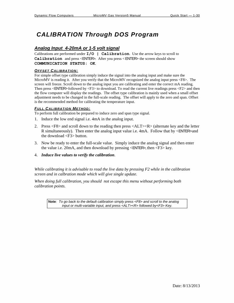
CALIBRATION Through DOS Program
Analog Input 4-20mA or 1-5 volt signal Calibrations are performed under I/O | Calibration. Use the arrow keys to scroll to
Calibration and press <ENTER>. After you press < ENTER> the screen should show
COMMUNICATION STATUS: OK.
OFFSET CALIBRATION :
For simple offset type calibration simply induce the signal into the analog input and make sure the
MicroMV is reading it. After you verify that the MicroMV recognized the analog input press <F8>. The
screen will freeze. Scroll down to the analog input you are calibrating and enter the correct mA reading.
Then press <ENTER> followed by <F3> to download. To read the current live readings press <F2> and then
the flow computer will display the readings. The offset type calibration is mainly used when a small offset
adjustment needs to be changed in the full-scale reading. The offset will apply to the zero and span. Offset
is the recommended method for calibrating the temperature input.
FULL CALIBRATION METHOD:
To perform full calibration be prepared to induce zero and span type signal.
1. Induce the low end signal i.e. 4mA in the analog input.
2. Press <F8> and scroll down to the reading then press <ALT><R> (alternate key and the letter
R simultaneously). Then enter the analog input value i.e. 4mA. Follow that by <ENTER> and
the download <F3> button.
3. Now be ready to enter the full-scale value. Simply induce the analog signal and then enter
the value i.e. 20mA, and then download by pressing <ENTER>, then <F3> key.
4. Induce live values to verify the calibration.
While calibrating it is advisable to read the live data by pressing F2 while in the calibration
screen and in calbration mode which will give single update.
When doing full calibration, you should not escape this menu without performing both
calibration points.
Note: To go back to the default calibration simply press <F8> and scroll to the analog
input or multi-variable input, and press <ALT><R> followed by<F3> Key.

Dynamic Flow Computers MicroMV Gas Version5 Manual Quick Start — 1-31
Date: 8/13/2013
RTD calibration: RTD Calibration is a 2-step process. The first step is a one time procedure to verify transducer linearity and is done at the time the meter is being setup. The second step is the routine calibration sequence. Step 1 – Linearity Verification 1. Use a Decade box with 0-150 °F settings. 2. Connect RTD cable to this resistive element for verification of linearity. Verify low and high points. It must be within ½ degree. 3. Connect the actual RTD element and compare with a certified thermometer. 4. If not within ½ degree do a Full Calibration (See Full Calibration below). If problem persists verify other elements such as RTD Probe, connections, shield, conductivity of connectors, etc. The purpose of the above procedure is to verify zero and span and make sure that the two points fall within the expected tolerance. Step 2 – Routine Calibration Once Linearity has been verified through Step 1, the routine calibration procedure is reduced to simply connecting the actual RTD and doing an offset point calibration (see offset calibration below). Calibration after that will be simple verification for the stability of the transmitter. If it drifts abnormally then you need to verify the other parts involved. RESET TO DEFAULT CALIBRATION
To go back to the default calibration simply press <F8> and scroll to the RTD input, and press
<ALT> <R> key followed by <F3> function key.
OFFSET CALIBRATION:
For offset calibration simply go to I/O | Calibration and press < ENTER>. Once the flow
computer shows communication status OK press <F8> function key and scroll to RTD. Induce a
live value and wait for 10 seconds for the reading to stabilize. Then enter the live value followed by <F3> function key to download the direct reading. The value entered must be in ohms only. FULL SCALE CALIBRATION:
1. Prepare low range resistive input (i.e., 80) and High range resistive input (i.e., 120). Go to the calibration menu and press <F8> function key. Scroll to the RTD input you are calibrating and press <ALT> <R> (key <ALT> and the letter R at the same time). Induce the low end
(80) resistive signal and then wait 10 seconds and enter 80 followed by pressing the <F3> function key.
2. Induce Higher range signal (120) and wait 10 seconds, then enter the number 120 ohm and
press the <F3> key.
3. Now verify the live reading against the flow computer reading.

Dynamic Flow Computers MicroMV Gas Version5 Manual Quick Start — 1-32
Date: 8/13/2013
Calibration of analog output: To calibrate the analog output against the end device follow the following steps:
1. Go to the calibration menu and press <F8>. Scroll down to analog output and press <ENTER>
, and then <ALT><R>. This will cause the flow computer to output the minimum possible
signal 4 mA. Enter the live output value reading in the end device i.e. 4 mA and press <F3>.
Now the flow computer will output full scale 20 mA. Enter the live output i.e. 20 then press
the <F3> key.
2. Now verify the output against the calibration device.

Dynamic Flow Computers MicroMV Gas Version5 Manual Quick Start — 1-33
Date: 8/13/2013
Multi-Variable Transmitters (Model 205) – DP and Pressure Calibrations are performed under I/O | Calibration. Use the arrow keys to scroll to
Calibration-Multi-Variable and press < ENTER>. After you press < ENTER> the screen
should show COMMUNICATION STATUS: OK.
OFFSET CALIBRATION
1. Induce live value for pressure or DP.
2. Go to Calibration - Multi-Variable menu.
3. Press <F8>, point to the value being calibrated, enter the correct value followed by <ENTER>,
then press <F3> key to download data.
4. Now read induce live values to verify the calibration.
FULL SCALE CALIBRATION
1. Press <F8>. Scroll to the parameter to be calibrated, then press <ALT><R>.
2. Induce the low range signal, then press <ENTER> followed by <F3>.
3. Induce the high range signal, then press <ENTER> followed by <F3>.
4. Now verify the live reading against the flow computer reading.
While doing calibration before downloading any of the calibrated values, it is a good practice to verify that
the Micro MV close reading to the induced value by pressing F2 to get a single update as many times as
needed. Do not use the escape key when performing full calibration until calibration is completed.
The DP reading must be re-calibrated for the zero offset after applying line pressure.

Dynamic Flow Computers MicroMV Gas Version5 Manual Quick Start — 1-34
Date: 8/13/2013
Multi-Variable Transmitters (Model 205)- RTD Calibrations are performed under I/O | Calibration. Use the arrow keys to scroll to
Calibration-Multi-Variable and press < ENTER>. After you press < ENTER> the screen
should show COMMUNICATION STATUS : OK.
RTD Calibration is a 2-step process. The first step is a one time procedure to verify transducer linearity and is done at the time the meter is being setup. The second step is the routine calibration sequence. Step 1 – Linearity Verification 1. Use a Decade box with 0-150 °F settings. 2. Connect RTD cable to this resistive element for verification of linearity. Verify low and high points. It must be within ½ degree. 3. Connect the actual RTD element and compare with a certified thermometer. 4. If not within ½ degree do a Full Calibration (See Full Calibration below). If problem persists verify other elements such as RTD Probe, connections, shield, conductivity of connectors, etc. The purpose of the above procedure is to verify zero and span and make sure that the two points fall within the expected tolerance. Step 2 – Routine Calibration Once Linearity has been verified through Step 1, the routine calibration procedure is reduced to simply connecting the actual RTD and doing an offset point calibration (see offset calibration below). Calibration after that will be simple verification for the stability of the transmitter. If it drifts abnormally then you need to verify the other parts involved. RESET TO DEFAULT CALIBRATION
To go back to the default calibration simply press <F8> and scroll to the RTD input, and press
<ALT> <R> key followed by <F3> function key.
OFFSET CALIBRATION:
For offset calibration simply go to I/O | Calibration and press < ENTER>. Once the flow
computer shows communication status OK press <F8> function key and scroll to RTD. Induce a
live value and wait for 10 seconds for the reading to stabilize. Then enter the live value followed by <F3> function key to download the direct reading. The value entered must be in degrees only. FULL SCALE CALIBRATION:
1. Prepare low range resistive input (i.e., 80) and High range resistive input (i.e., 120). Go to the calibration menu and press <F8> function key. Scroll to the RTD input you are calibrating and press <ALT> <R> (key <ALT> and the letter R at the same time). Induce the low end
(80) resistive signal and then wait 10 seconds and enter the equivalent temperature in degrees followed by pressing the <F3> function key.
2. Induce Higher range signal (120) and wait 10 seconds, then enter the temperature degrees equivalent to 120 followed by pressing the <F3> function key.
3. Now verify the live reading against the flow computer reading.

Dynamic Flow Computers MicroMV Gas Version5 Manual Quick Start — 1-35
Date: 8/13/2013
Verifying digital inputs and outputs Use the diagnostic menu. Scroll down by using the arrow keys to Diag | Diagnostic Data and
press <ENTER>. A live input and output is displayed. On the top of the screen pulse inputs and density
frequency input are shown. Compare the live value against the displayed value on the screen. Failure to
read turbine input could be a result of a bad preamplifier or the jumper selection for sine and square wave
input are not in the correct position. Refer to wiring diagram Wiring | Turbine for proper turbine
input wiring. Density input can be sine or square wave with or without DC offset. Minimum accepted
signal has to be greater than 1.2 volt peak to peak. Status input is shown below the frequency input to the
left of the screen. When the status input is on, the live diagnostic data will show ON. Minimum voltage to
activate the status is 6 volts with negative threshold of 2 volts. To activate the switch outputs to the on and
off position press <F8> in the diagnostic menu. After the screen freeze the cursor will point to switch
output one. Use the space bar to toggle the switch on/off and the <ENTER> key to advance to the next
switch. To exit press <ESC>. The switch outputs are open collector and require external voltage.

Dynamic Flow Computers MicroMV Gas Version5 Manual Data Entry — 2-1
Date: 8/13/2013
CHAPTER 2: Data Entry
and Configuration Menus
Introduction to the MicroMVG Software The Micro MV Gas software is constructed around a menu-driven organization
Configuration File through DOS Program
The Micro MV Gas software is constructed around a menu-driven organization. Begin your Micro MV
Gas software and, across the top of your screen, you see a bar like this:
This is called the menu bar. It consists primarily of series of topics–Port, Diag, and so forth. When
you move the cursor to a topic you will see a list–we will call it a menu list– of topics related to the main
topic on the menu bar.
At the bottom of the screen is the prompt bar. It informs you of appropriate actions that you can perform
while your cursor is at its present location. In this example:
you are informed that your valid choices are the four arrow keys, the<ENTER> key, and the <F1> key.
Another important area of the screen is the filename area. This is the rightmost section of the menu bar; it
informs you what configuration file you are presently viewing and editing. In the example above, you are
editing the file . When you first begin the SFC sotware, however, it will display
because no file has yet been chosen. Until you choose a file to edit or view, by opening either an existing
file or a new one, you will not be able to move from the File menu item.
The center portion of the screen is simply called the viewing area. Here you view either various menu lists
or the prompt window associated with an item in a menu list after it is selected (that is, after you press
<ENTER>). When you are in a prompt window the message appears in the filename area.
Under certain conditions you will have a screen where the viewing area takes up the whole screen and the
menu and/or prompt bars disappear. Examples of these are: the wiring diagrams, the calibration windows,
and the Diag windows.
About Displays the version number of EPROM and PC configuration menu. Press <Esc> to Exit.

Dynamic Flow Computers MicroMV Gas Version5 Manual Data Entry — 2-2
Date: 8/13/2013
File
Open a File Use this function to open an existing configuration file. After a file is opened it becomes the currently
active file; its contents can be viewed and its parameters can be edited.
When this function is chosen a list of existing configuration files is displayed. Use the cursor arrow keys to
move the cursor to your selection, then press the <ENTER> key.
Open a New File Create a new file to store all the programmed information for one Micro MV Gas Flow Computer. You are
prompted for the new file’s name of eight characters or less. If you enter the name of a pre-existing file,
the software informs you of this and prompts you for your file’s name again. After a file is opened it
becomes the currently active file; its contents can be viewed and its parameters can be edited.
Delete a File Delete a file when that file is no longer needed.
When this function is chosen a list of existing configuration files is displayed. Use the arrow keys to move
the cursor to your selection, then press <ALT><D> to delete the file.
Load File Use this function to exchange parameter values between the PC and the Micro MV Gas Flow Computer.
After this action is performed all parameter values in the Micro MV Gas Flow Computer and the currently
active file in the PC are identical.
To read all current parameters from the Micro MV Gas Flow Computer to the currently active file in the
PC, press the <F2> function key; this is called “uploading”.
To write all current parameters from the currently active file in the PC to the Micro MV Gas Flow
Computer, press the <F3> function key; this is called “downloading”.
View File Unlike every other file function, View File does not act upon configuration files. Instead, View File allows
the user to view files that were previously captured in a report. For capturing data in a report, look for
these items under the Report menu header:
Prev. Hourly Data
Prev. Daily Data
Prev. Month Data
Alarm Data
Audit Trail Report
Auto Data Retrieval
Current Data
When viewing a file use PageUp and PageDown to browse through it.

Dynamic Flow Computers MicroMV Gas Version5 Manual Data Entry — 2-3
Date: 8/13/2013
Save As Use Save As to save the parameters in the currently active file (that is, the parameter values currently being
edited) to a new file. You are prompted for the new file’s name of eight characters or less. If you enter the
name of a pre-existing file, the software informs you of this and prompts you for your file’s name again.
The original file will remain in memory.
Save When permanent modifications are performed on a file, user must save the new changes before exiting the
program, or proceeding to open a different file.
Save and Exit Exit the program and save the parameters that were changed.
Exit Exit without saving new modified parameters.

Dynamic Flow Computers MicroMV Gas Version5 Manual Data Entry — 2-4
Date: 8/13/2013
PORT
PC Communication Set Up
COMMUNICATION PORT NUMBER (1,2,3,4)
Enter the PC port used to communicate with the Micro MV Gas Flow Computer.
FLOW COMPUTER PORT NUMBER
There are three available ports in the Flow Computer. Port 1 is the RS-485 port that can only be a Modbus
port. Port 2 is the RS-232 port that can be user configurable as printer/Modbus. Port 3 is the RS-485 port
that can only be a Modbus port The PC set up must match the Micro MV Gas Flow Computer port set up.
UNIT ID NUMBER
The Unit ID Number is used strictly for communication purposes; it can take any value from 1 to 247. Only
one master can exist in each loop.
Note: Do not duplicate the Unit ID number in a single communication loop! This situation will lead to response collisions and inhibit communications to units with duplicate ID numbers.
MODBUS TYPE
Note: this parameter must be set the same for both the PC and the Micro MV Gas Flow Computer for communication to occur.
The Modbus Communication Specification is either Binary RTU or ASCII.
PARITY
Note: this parameter must be set the same for both the PC and the Micro MV Gas Flow Computer for communication to occur.
RTU - NONE
ASCII - EVEN or ODD
Set the parity to match the Modbus Type.
BAUD RATE
Note: this parameter must be set the same for both the PC and the Micro MV Gas Flow Computer for communication to occur.
Baud rate is defined as number of bits per second. The available selections are 1200, 2400, 4800, or 9600.
TRANSMIT DELAY
This Delay in milliseconds is used to allow handshaking between the PC and the Micro MV Gas Flow
Computer. The PC will hold the RTS line high for the specified Transmit Delay time. After that time
expires the data stream will begin transmitting. Transmit Delay is applicable regardless of the type of
communication with the Micro MV Gas Flow Computer (RS-232 or RS-485).
This function can be very useful, especially when using a half-duplex RS-485 port; otherwise the RS-485
port will never turn off. A delay of 50 milliseconds is normally sufficient.
Dynamic Flow Computers MicroMV Gas Version5 Manual Data Entry — 2-5
Date: 8/13/2013
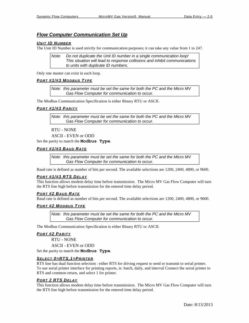
Flow Computer Communication Set Up
UNIT ID NUMBER
The Unit ID Number is used strictly for communication purposes; it can take any value from 1 to 247.
Note: Do not duplicate the Unit ID number in a single communication loop! This situation will lead to response collisions and inhibit communications to units with duplicate ID numbers.
Only one master can exist in each loop.
PORT #1/#3 MODBUS TYPE
Note: this parameter must be set the same for both the PC and the Micro MV Gas Flow Computer for communication to occur.
The Modbus Communication Specification is either Binary RTU or ASCII.
PORT #1/#3 PARITY
Note: this parameter must be set the same for both the PC and the Micro MV Gas Flow Computer for communication to occur.
RTU - NONE
ASCII - EVEN or ODD
Set the parity to match the Modbus Type.
PORT #1/#3 BAUD RATE
Note: this parameter must be set the same for both the PC and the Micro MV Gas Flow Computer for communication to occur.
Baud rate is defined as number of bits per second. The available selections are 1200, 2400, 4800, or 9600.
PORT #1/#3 RTS DELAY
This function allows modem delay time before transmission. The Micro MV Gas Flow Computer will turn
the RTS line high before transmission for the entered time delay period.
PORT #2 BAUD RATE
Baud rate is defined as number of bits per second. The available selections are 1200, 2400, 4800, or 9600.
PORT #2 MODBUS TYPE
Note: this parameter must be set the same for both the PC and the Micro MV Gas Flow Computer for communication to occur.
The Modbus Communication Specification is either Binary RTU or ASCII.
PORT #2 PARITY
RTU - NONE
ASCII - EVEN or ODD
Set the parity to match the Modbus Type.
SELECT 0=RTS,1=PRINTER
RTS line has dual function selection : either RTS for driving request to send or transmit to serial printer.
To use serial printer interface for printing reports, ie. batch, daily, and interval Connect the serial printer to
RTS and common return, and select 1 for printer.
PORT 2 RTS DELAY
This function allows modem delay time before transmission. The Micro MV Gas Flow Computer will turn
the RTS line high before transmission for the entered time delay period.

Dynamic Flow Computers MicroMV Gas Version5 Manual Data Entry — 2-6
Date: 8/13/2013
PRINTER BAUD RATE
Baud rate is defined as number of bits per second. The available selections are 1200, 2400, 4800, or 9600.
PRINTER NUMBER OF NULLS
This function is used because no hand shaking with the printer is available and data can become garbled as
the printer’s buffer is filled. The Micro MV Gas Flow Computer will send nulls at the end of each line to
allow time for the carriage to return. Printers with large buffers do not require additional nulls. If data is
still being garbled, try reducing the baud rate to 1200.

Dynamic Flow Computers MicroMV Gas Version5 Manual Data Entry — 2-7
Date: 8/13/2013
Dial
Use the cursor arrow keys to move the cursor to the desired phone number and press ENTER. Dial’s
display indicates the owner of each phone number according to the Phone Book.
Dial cannot add new phone numbers; it can only dial numbers that have previously been entered in the
Phone Book.
Example: T,9,1800-530-5539 instructs the dialer to use tone dialing, pause, dial 9 for an outside line, pause,
then dial the number. See Phone Book for more information.
Phone Book Phone Book lists all the phone numbers with the phone’s owner New numbers can be added to the list.
<Arrow Keys> Select Number to Modify or Delete.
<A> Add new entry to phonebook.
<ALT> + <D> Delete selected entry.
<M> or <ENTER> Modify selected entry.
<Esc> Exit and save changes.
Phone Book Edit Type name, press <TAB>, and type phone number. Press <ENTER> to save, <Esc> to leave entry
unchanged.
In the phone number the following codes may be used:
<0-9> Dial digit
<P> Change to pulse dialing
<T> Change to tone dialing
<Comma> Pause
Example: T,9,1800-530-5539 instructs the dialer to use tone dialing, pause, dial 9 for an outside line,
pause, then dial the number.
Modem Setup
<Modem Dial Prefix> Enter the string sent to the modem before the phone number.
Normally either "ATDT" (dial tone) or "ATDP" (dial pulse)
<Modem Dial Suffix> Enter the string sent to the modem after the phone number.
Normally just "^M" (CR)
<Modem Hangup String> Enter the string sent to the modem to hang-up the phone.
See your modem manual for other characters.
Hang-up Phone
Press ENTER to send the Modem Hang-up string (Defined in Modem Setup) to the modem.
Note : Hand shake and error checking should be turned off. Commands to turn off the hand shake vary between modems. Check your modem manual. Typical command - AT&K0, AT&Y0.

Dynamic Flow Computers MicroMV Gas Version5 Manual Data Entry — 2-8
Date: 8/13/2013
DIAG
Read Single Flow Computer Communication Setup Press <F2> and the configuration program will attempt to communicate with a single Micro MV Gas Flow
Computer at different baud rates and formats.
Failure to communicate can occur because of a communication wiring problem, wrong PC port selection,
communication parameter mismatch between PC and Micro MV Gas Flow Computer (Modbus type,
parity, baud rate, etc.) or lack of power to the Micro MV Gas Flow Computer. To use this feature, the user
must insure that only one Micro MV Gas Flow Computer is connected to the PC. More than one Micro
MV Gas Flow Computer in the loop will cause data collisions and unintelligible responses.
Diagnostic Data
Diagnostic Data shows real-time, live data. Use it to monitor switch outputs, status inputs, analog
inputs and outputs, analog frequency, failure codes and so forth. To control the switch outputs manually
use the <F8> function key, press the SPACE BAR to change activity, and use <ENTER> key to move to
next switch.
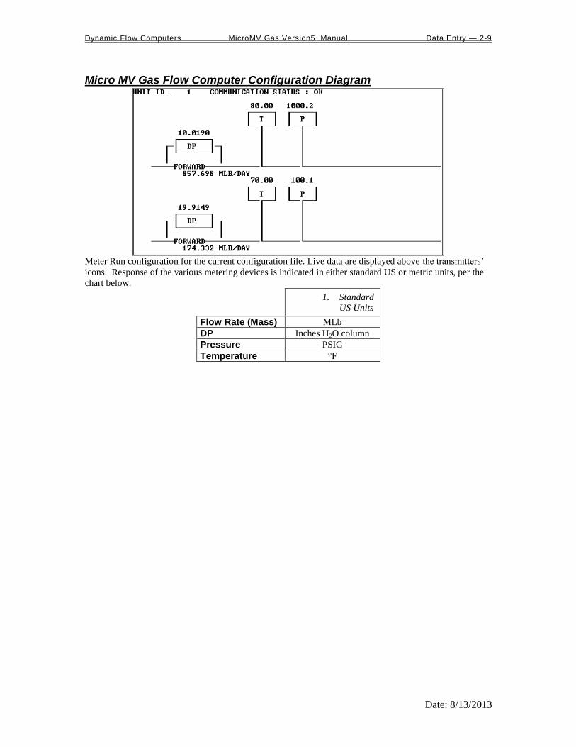
Dynamic Flow Computers MicroMV Gas Version5 Manual Data Entry — 2-9
Date: 8/13/2013
Micro MV Gas Flow Computer Configuration Diagram
Meter Run configuration for the current configuration file. Live data are displayed above the transmitters’
icons. Response of the various metering devices is indicated in either standard US or metric units, per the
chart below.
1. Standard
US Units
Flow Rate (Mass) MLb
DP Inches H2O column
Pressure PSIG
Temperature °F

Dynamic Flow Computers MicroMV Gas Version5 Manual Data Entry — 2-10
Date: 8/13/2013
METER
Set Up All items in this section are listed in the submenu Meter | Set Up | ….
METER BANK
Configure for single or dual meters per individual Micro MV Gas Flow Computer. Enter “1” if two meters
will be connected to the flow computer.
S INGLE OR DUAL STREAMS
Single stream can be single meter or bank of two meters. Dual streams allow the user to monitor
independent products on separate streams simultaneously.
STATION TOTAL
Station total can add meter one and two, subtract meter one from meter two, or just ignore this feature by
selecting none. Station Total does not affect, destroy or otherwise alter the data from either meter. When
Station Total is other than none, an additional data parameter, Station Total, is generated by the Micro MV
Gas Flow Computer and appears in reports and on the live display monitor.
Station total is not accessible when Meter Bank = 0.
COMMON PARAMETERS
Meter | Set Up | Common [Temperature/Pressure/Density]
This feature allows the Micro MV Gas Flow Computer to use the transmitters on meter one to substitute
and compensate for meter two.
USE STACK DP
The Micro MV Gas Flow Computer allows the user to select dual DP transmitters on each meter for better
accuracy and a higher range flow. Use in conjunction with the DP Switch High % parameter setting.
DP SWITCH H IGH %
The Micro MV Gas Flow Computer will begin using the high DP when the low DP reaches the percent
limit assigned in this entry. Example: DP low was ranged from 0-25 inches and switch % was set at 95%.
When low DP reaches 23.75 in (= 0.95 * 25) the Micro MV Gas Flow Computer will begin using the high
DP provided the high DP did not fail. When the high DP cell drops below 23.75, the Flow Computer will
start using the Low DP for measurement.
DENSITY TYPE
If live density is connected to the flow computer, user must enter the density type. Raw density frequency
or a 4-20mA input can be selected. This density will be used to calculate mass flow and net flow.
Density Type
Densitometer
Type 0 None
Type 1 4–20 mA
Density 4–20 mA Type*
Type 0 Density Signal 4-20mA in LB/FT3
Type 1 SG Signal 4-20mA
Type 2 UGC
Type 3 Sarasota
Type 4 Solartron
DENSITY 4-20MA TYPE*
Note that this type of input requires the user to choose a subtype, as indicated in the table above.
*Note: Only Type 1 calculation (Density in LB/FT3) is appropriate for gas measurements; therefore the software chooses that option for you automatically. Density is calculated in LB/FT3.

Dynamic Flow Computers MicroMV Gas Version5 Manual Data Entry — 2-11
Date: 8/13/2013
USE METER TEMPERATURE AS DENSITY TEMPERATURE
Meter | Set Up | Use Meter Temp as Dens.Temp#1
Meter | Set Up | Use Meter#2 Temp as Dens.Temp#2
To allow the meter temperature to calculate the effect of temperature on the densitometer. Make sure the
meter and density temperature are similar to avoid measurement errors.
Meter Data All items in this section are listed in the submenu Meter | Meter Data | ….
METER LOCATION
Up to 20 characters. This entry appears only in the report and serves no other function.
METER ID
Up to 8 characters. This function will serve as Meter Tag.
FLOW EQUATION TYPE (0-3)
0 = AGA3 (OLD AGA3, 1985 Orifice Equations)
1 = API 14.3 (NEW AGA3, 1992 Orifice Equations)
2 = AGA7 (Frequency Type Input)
3 = Venturi
Select the desired calculation mode. API 14.3 is the latest orifice calculations introduced in 1992. AGA3 is
the orifice calculation that was used previously. All new installations are recommended to use API 14.3 for
orifice calculations.
Here is the prompt window for one equation type. This prompt window pops up when you enter a valid
value in the Flow Equation Type line and press ENTER.
DENSITY OF DRY A IR MLB /MOL
Typical value would be 28.9625.
RELATIVE DENSITY
The real gas relative density is used in the calculations of the compressibility factor, flowing and reference
densities (required only when AGA8 or NX19 is used).
FLOW RATE LOW /H IGH L IMIT
The high/low flow rate alarm is activated, when the flowrate exceeds or is below the set limit. The alarm
will be documented with time, date, and totalizer.
DENSITY CALCULATION TYPE (0-3)
Calc. # Calculation Type Comments and Limitations
0 = NX19
1 = AGA8 Gross Method 1 Relative Density: 0.554–0.87
Heating.Value: 477–1150 BTU/SCF
2 = AGA8 Gross Method 2 Relative Density: 0.554–0.87
Heating.Value 477–1150 BTU/SCF
3 = AGA8 Detail Method Relative Density: 0.07–1.52
Heating.Value 0–1800 BTU/SCF AGA 8 detail method can be used for gases other than natural gas, such as methane, carbon dioxide, ethane,
and hydrogen sulfide.

Dynamic Flow Computers MicroMV Gas Version5 Manual Data Entry — 2-12
Date: 8/13/2013
AGA3 DATA
To set AGA3 flow parameters, set Meter | Meter Data | Flow Equation Type = 0 and
press ENTER. You will then access a submenu in which you can set the parameters below.
Pipe I.D. Inches
Orifice ID Inches
Pipe ID in inches is the measured inside pipe diameter to 5 decimals at reference conditions. Orifice ID in
inches is the measured diameter of the orifice at reference conditions.
DP Cutoff
The Micro MV Gas Flow Computer suspends all calculations whenever the DP, in inches of water column,
is less than this value. This function is vital for suppressing extraneous data when the DP transmitter drifts
around the zero mark under no-flow conditions.
Y Factor (0=None,1=Upstream,2=Downstream)
Y factor is the expansion factor through the orifice. The user must enter the position of the pressure and
temperature sensors. Select y=1 if the sensors are installed upstream of the orifice plate. Select y=2 if the
sensors are down stream of the orifice plate.
Select 0=Flange Tap, 1=Pipe Tap
Tap position is where the differential transmitter is fitted. Select 0 = flange fitted or 1 = pipe fitted.
Isentropic Exponent (Specific Heat)
Ratio of specific heat is a constant associated with each product. Even though it varies slightly with
temperature and pressure, in most cases it is assumed to be a constant.
Viscosity in Centipoise
Even though viscosity will shift with temperature and pressure changes, the effect on the calculations is
negligent. Therefore using a single value is appropriate in most cases. Enter viscosity in centipoise.
Reference Temperature of Orifice
Reference temperature of orifice is the temperature at which the orifice bore internal diameter was
measured. Commonly 68 °F is used.
Orifice Thermal Expansion Coeff. E-6
Orifice thermal expansion is the linear expansion coefficient of orifice material.
Type 304 and 316 Stainless 9.25 E-6
Monel 7.95 E-6
Carbon Steel 6.20 E-6
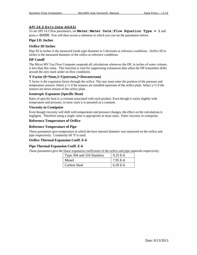
Dynamic Flow Computers MicroMV Gas Version5 Manual Data Entry — 2-13
Date: 8/13/2013
API 14.3 DATA (NEW AGA3)
To set API 14.3 flow parameters, set Meter | Meter Data | Flow Equation Type = 1 and
press ENTER. You will then access a submenu in which you can set the parameters below.
Pipe I.D. Inches
Orifice ID Inches
Pipe ID in inches is the measured inside pipe diameter to 5 decimals at reference conditions. Orifice ID in
inches is the measured diameter of the orifice at reference conditions.
DP Cutoff
The Micro MV Gas Flow Computer suspends all calculations whenever the DP, in inches of water column,
is less than this value. This function is vital for suppressing extraneous data when the DP transmitter drifts
around the zero mark under no-flow conditions.
Y Factor (0=None,1=Upstream,2=Downstream)
Y factor is the expansion factor through the orifice. The user must enter the position of the pressure and
temperature sensors. Select y=1 if the sensors are installed upstream of the orifice plate. Select y=2 if the
sensors are down stream of the orifice plate.
Isentropic Exponent (Specific Heat)
Ratio of specific heat is a constant associated with each product. Even though it varies slightly with
temperature and pressure, in most cases it is assumed as a constant.
Viscosity in Centipoise
Even though viscosity will shift with temperature and pressure changes, the effect on the calculations is
negligent. Therefore using a single value is appropriate in most cases. Enter viscosity in centipoise.
Reference Temperature of Orifice
Reference Temperature of Pipe
These parameters give temperature at which the bore internal diameter was measured on the orifice and
pipe respectively. Commonly 68 °F is used.
Orifice Thermal Expansion Coeff. E-6
Pipe Thermal Expansion Coeff. E-6
These parameters give the linear expansion coefficients of the orifice and pipe materials respectively.
Type 304 and 316 Stainless 9.25 E-6
Monel 7.95 E-6
Carbon Steel 6.20 E-6
Dynamic Flow Computers MicroMV Gas Version5 Manual Data Entry — 2-14
Date: 8/13/2013
AGA 7 DATA (FREQUENCY )
To set AGA 7 flow parameters, set Meter | Meter Data | Flow Equation Type = 2 and
press ENTER. You will then access a submenu in which you can set the parameters below.
K Factor
K Factor is the number of pulses per unit volume, i.e. 1000 pulses/CF. The meter’s tag would normally
indicate the K Factor.
Meter Factor
Meter Factor is a correction to the K Factor for this individual meter, applied multiplicatively to the K
factor.
Flow Cutoff Frequency
The Micro MV Gas Flow Computer will quit totalizing when the turbine frequency (or other frequency
input) is below this set limit. This feature is to reduce extraneous noise appearing as volume data when the
meter is down for period of time.
This value is entered as pulses per second.

Dynamic Flow Computers MicroMV Gas Version5 Manual Data Entry — 2-15
Date: 8/13/2013
VENTURI DATA
To set Venturi flow parameters, set Meter | Meter Data | Flow Equation Type = 3 and
press ENTER. You will then access a submenu in which you can set the parameters below.
Pipe I.D. Inches
Orifice ID Inches
Pipe ID in inches is the measured inside pipe diameter to 5 decimals at reference conditions. Orifice ID in
inches is the measured diameter of the orifice at reference conditions.
DP Cutoff
The Micro MV Gas Flow Computer suspends all calculations whenever the DP, in inches of water column,
is less than this value. This function is vital for suppressing extraneous data when the DP transmitter drifts
around the zero mark under no-flow conditions.
Y Factor (0=None,1=Upstream,2=Downstream)
Y factor is the expansion factor through the venturi. The user must enter the position of the pressure and
temperature sensors. Select y=1 if the sensors are installed upstream of the venturi. Select y=2 if the sensors
are down stream of the venturi.
Isentropic Exponent (Specific Heat)
Ratio of specific heat is a constant associated with each product. Even though it varies slightly with
temperature and pressure, in most cases it is assumed as a constant.
Reference Temperature of Orifice
Reference Temperature of Pipe
These parameters give temperature at which the bore internal diameter was measured on the orifice and
pipe respectively. Commonly 68 °F is used.
Pipe Thermal Expansion Coeff. E-6
Pipe thermal expansion is the linear expansion coefficient of pipe material.
Type 304 and 316 Stainless 9.25 E-6
Monel 7.95 E-6
Carbon Steel 6.20 E-6
Discharge Coefficient C
Typical value is 0.995.
Mass (MLB / HR) = 0.0997424 C Y F d
1- DP 3.6
a
2
4

Dynamic Flow Computers MicroMV Gas Version5 Manual Data Entry — 2-16
Date: 8/13/2013
Linear Factor Meter | Linear Factor
Enter the different correction factors for the meter at different flow rates. The Micro MV Gas Flow
Computer will perform linear interpolation each second. Notice that even though using this feature
enhances the measurement accuracy and range, performing audit trail on a linearized meter factor is very
difficult.

Dynamic Flow Computers MicroMV Gas Version5 Manual Data Entry — 2-17
Date: 8/13/2013
Other Parameters All parameters in this section are in the submenu Meter | Other Parameters | … unless otherwise
noted.
DAY START HOUR (0-23)
Day start hour is used for daily totalizer reset operation.
COMPANY NAME
Up to 20 characters. The company name appears in the reports.
FLOW RATE SELECTION
The flow rate will be based on daily basis, hourly, or minute.
FLOW RATE AVERAGED SECOND
The flow rate is averaged for 1-10 seconds to minimize fluctuating flow rate conditions. This number
averages the current flow rate by adding it to the previous seconds’ flow rate, and then displays an averaged
smoothed number. Only a low resolution pulse meter requires this function.
D ISABLE ALARMS
Use Disable Alarms to ignore alarms. When the alarm function is disabled alarms are not logged. Alarms
are also not logged if the DP is below the cut-off limit.
PRINT INTERVALS IN M INUTES (0-1440)
When the second port (RS-232) of the Micro MV Gas Flow Computer is configured as printer port, a
snapshot report is generated every print interval (i.e., every five minutes, every hour, or every ten hours).
BASE TEMPERATURE
The basis reference temperature for all corrections. Used, for example, when seller contracts to sell to buyer
at an agreed base temperature. Typically 60.0 °F in US units, 15 °C in Metric units.
BASE PRESSURE
The basis reference pressure for all corrections. Used, for example, when seller contracts to sell to buyer at
an agreed base pressure. Typical values are 14.73 PSIA for US units, 1.01325 bar in Metric units.
ATMOSPHERIC PRESSURE
This pressure is the local pressure or contracted atmospheric pressure to be used. Typical value is 14.696
PSIA.

Dynamic Flow Computers MicroMV Gas Version5 Manual Data Entry — 2-18
Date: 8/13/2013
RUN SWITCHING
Run switching is used to switch from tube one to tube two, when flow rate reaches certain limits. The
Micro MV Gas Flow Computer has one active output that can be dedicated to this function. The time delay
allows for some delay in switching.
Note: if Run Switching is being used, then the meter should be configured for a single stream (see Set Up under Meter).
RUN SWITCH H IGH SET POINT
When this flow rate value is exceeded and after the delay timer expires, the switch output will activate.
This output normally opens meter run two. The Micro MV Gas Flow Computer provides open collector
type output that requires external power.
RUN SWITCH LOW SET POINT
When the flow rate drops below this value and stays below it until the delay timer expires, the output
switch will be turned off to shut meter two.
PULSE OUTPUT AN D PULSE OUTPUT W IDTH
Pulse Output is used to activate a sampler or external totalizer. The number selected will be pulses per unit
volume or per unit mass. If 0.1 pulse is selected, the one pulse will be given every 10 unit volumes has
passed through the meter.
Pulse Output Width is the duration, in milliseconds, of one complete pulse cycle (where each cycle is the
pulse plus a wait period, in a 50/50 ratio). For example: if POW = 500 msec, the Micro MV Gas Flow
Computer at most can produce one pulse each second regardless of the pulse per unit volume selected (500
msec pulse + 500 msec wait). If POW = 10 msec the Micro MV Gas Flow Computer can produce up to 50
pulses per second.
The Micro MV Gas Flow Computer’s maximum pulse output is 125 pulses/sec. The Pulse Output in
combination with the Pulse Output Width should be set appropriately.

Dynamic Flow Computers MicroMV Gas Version5 Manual Data Entry — 2-19
Date: 8/13/2013
Date and Time Meter | Date/Time
The PC software will show the current date and time from the PC. Press to download that date and time
to the flow computer. Press to upload the date and time from the flow computer.
Parameter Overrides
Temperature Override Meter | Temperature Override
Pressure Override Meter | Pressure Override
Heating Value Override Meter | Heating Value Override
Base Density Override Meter | Base Dens Override
FPV Override Meter | Fpv Override
An override value is entered when no live parameter value is available, or when a different value from live
value should be used. In the diagnostic screen, the fail code will appear as 9. Zero in the data entry
indicates use live value.
Heating Value Override is used in the AGA8 calculation GROSS METHOD 1. In addition the heating
value totalizer requires the heating value; without a BTU override value entered, the Energy Flowrate will
always equal zero. Enter this number in BTU/SCF(standard cubic feet).
Base Density Override is used to override the calculated base density and affects the net calculations only.
For products other than natural gas, you must enter base density override for net calculations.
FPV override: used to enter a value to override the NX19 supercompressibility factor.

Dynamic Flow Computers MicroMV Gas Version5 Manual Data Entry — 2-20
Date: 8/13/2013
Security Code Meter | Security Code
Several levels of security codes have been selected to fit different levels of responsibility. Up to six
numeric code can be used for each entry. If the security code is not used, then there will not be any security
code prompt in the menu.

Dynamic Flow Computers MicroMV Gas Version5 Manual Data Entry — 2-21
Date: 8/13/2013
INPUT/OUTPUT
Transducer Input Assignment Parameters in this section are in the submenu I/O | Transducer Input Assignment | …
unless otherwise noted. Throughout this section the label [Parameter]
includes all these parameters unless otherwise noted: DP,
Temperature, Pressure, Density, and Dens.Temperature.
Note: This prompt window has more parameters that can
be seen in the above example. Others may be
reached by scrolling down the list. The actual
naumber of parameters that need to be set is a
function of the number of (nonzero) input
assignments on Meters 1 and 2.
TRANSDUCER INPUT ASSIGNMENT
This discussion applies to all [Parameter] Assignment parameters.
The Micro MV Gas Flow Computer provides 4 analog inputs, 4 status input/ switch outputs, one density
frequency input, two turbine inputs, one 4 wire RTD inputs, and 2 multi variable inputs.. In order for the
Micro MV Gas Flow Computer to read the live input, the input must be properly assigned and properly
wired.
0= Not Used 4= Analog#4 7 = Dens.Freq (Not Selectable)
1= Analog#1 5= RTD 10 = Multi. Variable Module #1
2= Analog#2 11 = Multi. Variable Module #2
3= Analog#3
SPARE ASSIGNMENT
Spare input is used for display and alarm purpose only. It is not used in the calculation process. To read
spare input value, use the diagnostic screen.
4MA
Enter the 4mA value for the transducer.
Note that this value cannot be edited if [Parameter] Assignment = 0. Therefore to set the
parameter Meter#1 Temperature @4mA the Temperature Assignment parameter
cannot equal zero.
Note that any [Parameter] can potentially have a @4mA setting.
20MA
Enter the 20mA value for the transducer.
Note that this value cannot be edited if [Parameter] Assignment = 0. Therefore to set the
parameter Meter#1 Temperature @20mA the Temperature Assignment parameter
cannot equal zero.
Note that any [Parameter] can potentially have a @20mA setting.
LOW /H I L IMIT
Enter the low and high limits. When live value exceeds high limit or less than low limit, a alarm log will be
generated.
Note that this value cannot be edited if [Parameter] Assignment = 0. Therefore to set the
parameter Meter#1 Temperature Low Limit the Temperature Assignment
parameter cannot equal zero.

Dynamic Flow Computers MicroMV Gas Version5 Manual Data Entry — 2-22
Date: 8/13/2013
MAINTENANCE VALUE
The value to be used when the transmitter fails, or while calibrating. For calibration, set fail code to 1 while
calibrating.
Note that this value cannot be edited if [Parameter] Assignment = 0. Therefore to set the
parameter Meter#1 Temperature Maintenance the Temperature Assignment
parameter cannot equal zero.
Note that any [Parameter] can potentially have a Maintenance setting.
FAIL CODE
Fail Code 0: always use the live value even if the transmitter failed.
Fail Code 1: always use the maintenance value
Fail Code 2: use maintenance value if transmitter failed. i.e. 4-20mA is above 21.75 or
below 3.25)
Note that this value cannot be edited if [Parameter] Assignment = 0. Therefore to set the
parameter Meter#1 Temperature Maintenance the Temperature Assignment
parameter cannot equal zero.
Note that any [Parameter] can potentially have a Maintenance setting.
DENSITY PERIOD LOW /H IGH L IMITS
Density Period is the time period in micro-second. The densitometer fails if the density period exceeds the
density period low or high limits. If the densitometer fails and density fail code is set to 2, the maintenance
value will be used.
Transducer Tag ID I/O | Transducer Tag ID
Up to 8 alphanumeric ID number. The transmitters are referred to according to the TAG ID. All alarms
are labeled according to TAG ID.

Dynamic Flow Computers MicroMV Gas Version5 Manual Data Entry — 2-23
Date: 8/13/2013
Calibration Mode I/O | Calibrate Mode
CALIBRATE MODE
To calibrate Flow Computer, totalizers will continue at same rate where live parameters will show actual
value, i.e. flowrate, DP, pressure etc. Enter ‘1’ to enable this feature.
SET T IME (1-9 HOUR )
This entry is the duration for the calibrate mode. After time expires, the Micro MV Gas Flow Computer
will resume its normal operation.
METER #1/#2 MASS FLOWRATE
Override the mass flowrate during the calibration.
Calibration See details in chapter 1

Dynamic Flow Computers MicroMV Gas Version5 Manual Data Entry — 2-24
Date: 8/13/2013
Status Input /Switch Output Assignment I/O | Status Input/Switch Output Assignment
Assignment 1. Comments
1. N/A
2 Calibration Mode
3 Event Status
4 Alarm Acknowledge Reset the previous occurred alarms output bit
Switch Output Assignment User can assign an output to each of the Micro MV Gas Flow Computer’s output switches from this list.
The Micro MV Gas Flow Computer switch outputs are open collector type, requiring external D.C power.
Outputs in the top list,”Pulse Outputs”, require a definition of pulse output per unit volume. Therefore a
Pulse Output Width must be defined when one of these switch types are chosen. These outputs are
available through swtiches 1 or 2 only.
Outputs in the bottom list,”Contact Type Outputs”, are ON/OFF type outputs. They can be assigned to any
of the four switch outputs.
Switches 1 and 2 can be pulse or contact type output; switches 3, 4 are contact-type output only.
ASSIGNMENTS - PULSE OUTPUTS
Meter 1 Meter 2 Station
Gross 101 105 109
Net 102 106 110
Mass 103 107 111
Energy 104 108 112
ASSIGNMENTS - CONTACT TYPE OUTPUTS
Meter 1 Meter2 Meter-Independent Parameters
Temperature Low 126 136 Day Ended 119
Temperature High 127 137 Dens. Period Low 146
Pressure Low 128 138 Dens. Period High 147
Pressure High 129 139 AGA8 Out of Range 148
Density Low 130 140 NX19 Out of Range 149
Density High 131 141 N/A 150
Dens.Temp Low 132 142 Active Alarms 151
Dens.Temp High 133 143 Occurred Alarms 152
DP Low 134 144 WatchDog 157
DP High 135 145 Remote Control 158
Meter Down 120 123 Run Switch 159
Flow Rate Low 121 124
Flow Rate High 122 125
N/A
N/A
Note: Assignments 113–118 are not used.

Dynamic Flow Computers MicroMV Gas Version5 Manual Data Entry — 2-25
Date: 8/13/2013
Analog Output Assignment 4-20mA selection must be proportional and within the range of the selected parameter.
ASSIGNMENTS :
Meter 1 Meter 2 Station
Gross Flow Rate 1 5 9
Net Flow Rate 2 6 10
Mass Flow Rate 3 7 11
Energy Flow Rate 4 8 12
Meter 1 Meter2 Meter-Independent Parameters
DP 13 21 Spare #1 33
Temperature 14 22 Spare #2 34
Pressure 15 23 Remote Control* 35
Density 16 24
Examples:
9 = Station Gross Flowrate
30 = Meter 1 Specific Gravity
25 = Meter 2 Density Temperature
Density Temp 17 25
Dens.b 18 26
DP LOW 19 27
DP HIGH 20 28
Specific Gravity 30 32
Note: Assignments 29 and 31 are not used.
*Note : Remote control output can be controlled through the Modbus communication link.
Note: Dens.b = Base Density
DP = Differential Pressure
Remote Control Analog Output Setpoint Set analog output assignment to 35 (remote control), then enter 0-100 percentage to control the analog
output.

Dynamic Flow Computers MicroMV Gas Version5 Manual Data Entry — 2-26
Date: 8/13/2013
Micro MV Gas Flow Computer Display Assignment Display assignment select up to 16 assignments. The Micro MV Gas Flow Computer will scroll through
them at the assigned delay time.
ASSIGNMENT
4 Digits – 1st
: Forward/Reverse – 0:Forward,1:Reverse
2nd
– Meter Number – 1:Meter#1, 2:Meter#2, 3:Station
3rd, 4th
: Selection
Selection Description
01 Flow Rate
02 Daily Total
03 Cum. Total
04 Previous Daily total
05 DP/DP Low, High
06 Temperature, Pressure
07 Density, Density at Base
08 Density Freq, Dens.Period, Un-Corr. Density
09 Density Temperature, Density Pressure
10 Flow and Density Calculation Type
11 Spare #1, Spare #2
12 Previous Day AVG Temperature, Pressure, SG
13 Alarms
14 Date, Time
Examples:
101= Meter#1 Flowrate
102= Meter #1 Daily Total
302= Station Daily Total
113= Meter#1 Alarm
14= Date, Time

Dynamic Flow Computers MicroMV Gas Version5 Manual Data Entry — 2-27
Date: 8/13/2013
Modbus Shift Reassigns Modbus address registers on the Micro MV Gas Flow Computer to predefined Modbus registers
for easy polling and convenience. Use Modbus Shift to collect values in scattered Modbus registers into a
consecutive order. The Micro MV Gas Flow Computer will repeat the assigned variables into the selected
locations.
Note: some Modbus registers are 2 byte/16 bit, and some are 4 byte/32 bit. Register size incompatibility
could cause rejection to certain address assignments. Refer to the Modbus Address Table Registers in
Chapter 5.
Example: you want to read the current status of switches #1 and #2 (addresses 2617 and 2618) and the
Daily Gross Total for Meter #1 ( addresses 3173 ). Make assignments such as:
3082=2617 (2 bytes)
3083=2618 (2 bytes)
3819=3173 (4 bytes)
Modbus Shift – Floating Point Use Modbus Shift to collect values in scattered Modbus floating point registers into a consecutive order.
The Micro MV Gas Flow Computer will repeat the assigned variables(Refer to the Modbus Address Table
Registers in Chapter 5) into the selected locations(7501-7600)

Dynamic Flow Computers MicroMV Gas Version5 Manual Data Entry — 2-28
Date: 8/13/2013
BOOLEAN STATEMENTS
From the Micro MV Gas Flow Computer Configuration Software, Point cursor to 'I/O', scroll down to 'Boolean Statements', then press 'Enter' and the following menu will be displayed: Boolean Points – 4 digits (0001-0800, 7831-7899) F2:UPLOAD,F3:DOWNLOAD
#70 #80 #90
#71 #81 #91
#72 #82 #92
#73 #83 #93
#74 #84 #94
#75 #85 #95
#76 #86 #96
#77 #87 #97
#78 #88 #98
#79 #89 #99
Enter the boolean statements (up to 30 statements). Each statement contains up to two boolean variables (optionally preceded by ‘/’) and one of the boolean function (&, +, *). 4 digits are required for referencing programmable variables or boolean points. (Example: 0001)

Dynamic Flow Computers MicroMV Gas Version5 Manual Data Entry — 2-29
Date: 8/13/2013
PROGRAM VARIABLE STATEMENTS
From the Micro MV Gas Flow Computer Configuration Software, Point cursor to 'I/O', scroll down to `Program Variable Statements', then press 'Enter' and the following menu will be displayed: Program Variable Statements – 78xx (4 digits), F2:UPLOAD, F3:DOWNLOAD
#31 #54 #77
#32 #55 #78
#33 #56 #79
#34 #57 #80
#35 #58 #81
#36 #59 #82
#37 #60 #83
#38 #61 #84
#39 #62 #85
#40 #63 #86
#41 #64 #87
#42 #65 #88
#43 #66 #89
#44 #67 #90
#45 #68 #91
#46 #69 #92
#47 #70 #93
#48 #71 #94
#49 #72 #95
#50 #73 #96
#51 #74 #97
#52 #75 #98
#53 #76 #99
Enter the user programmable statements (up to 69 statements). Each statement contains up to three variables and separated by one of the mathematical functions. 4 digits are required for referencing programmable variables or boolean points. (Example: 0001+7801)

Dynamic Flow Computers MicroMV Gas Version5 Manual Data Entry — 2-30
Date: 8/13/2013
BOOLEAN STATEMENTS AND FUNCTIONS
Each programmable boolean statement consists of two boolean variables optionally preceded a
boolean 'NOT' function (/) and separated by one of the boolean functions (&, +,*). Each
statement is evaluated every 100 milliseconds. Boolean variables have only two states 0 (False, OFF) or 1 (True, ON). Any variable (integer or floating point) can be used in the boolean statements. The value of Integer or floating point can be either positive (TRUE) or negative (FALSE).
Boolean Functions Symbol
NOT /
AND &
OR +
EXCLUSIVE OR *
Boolean points are numbered as follows: 0100 through 0199 Meter #1 Boolean Points 0200 through 0299 Meter #2 Boolean Points
1st digit – always 0, 2
nd digit – meter number.
0n01 Gross Flow Pulses 0n02 Net Flow Pulses 0n03 Mass Flow Pulses 0n04 Energy Flow Pulses 0n05 Meter Active 0n06 Spare 0n07 Any Alarms 0n08-0n10 Spare 0n11 DP Override in use 0n12 Temperature Override in use 0n13 Pressure Override in use 0n14 Density Override in use 0n15 Densitometer Temperature Overide in use 0n16-0n19 Spare 0n20 Flow Rate High Alarm 0n21 Flow Rate Low Alarm 0n22 Temperature High Alarm 0n23 Temperature Low Alarm 0n24 Pressure High Alarm 0n25 Pressure Low Alarm 0n26 Density High Alarm 0n27 Density Low Alarm 0n28 Density Temp High Alarm 0n29 Density Temp Low Alarm 0n30 DP High Alarm 0n31 DP Low Alarm
301 through 0699 Spare 0701 through 0799 Station Boolean Points
0701 Station Gross Flow Pulses 0702 Station Net Flow Pulses 0703 Station Mass Flow Pulses 0704 Station Energy Flow Pulses 0705-0710 Spare 0711 Run Switch
0801 through 0899 Command Boolean Points 0801 Spare
0802 Alarm Acknowledge
See Boolean Statements.

Dynamic Flow Computers MicroMV Gas Version5 Manual Data Entry — 2-31
Date: 8/13/2013
VARIABLE STATEMENTS AND MATHEMATICAL FUNCTIONS
Each statement can contain up to 3 variables or constants. Function Symbol ADD + Add the two variables or constant
SUBTRACT - Subtract the variable or constant
MULTIPLY * Multiply the two variables or constant
DIVIDE / Divide the two variables or constants
CONSTANT # The number following is interpreted as a constant
Example: 7801=#2
POWER & 1st variable to the power of 2
nd variable
ABSOLUTE $ unsigned value of variable
EQUAL = Move result to another variable Variable within the range of 7801-7830,
7831-7899 (floating points) Variable within the range of 5031-5069 (long integer)
IF STATEMENT ) Compares the variable to another
Example- 7801)T7832 (Go to 7832 if var 7801 >= 0) GOTO STATEMENT T Go to a different statement
COMPARE % Compare a value (equal to)
Natural Log L Natural Log of variable
Greater > Greater than or equal to
Example: 7801>7802T7832 (Go to 7832 if 7801>=7802) Order of precedence – absolute, power, multiply, divide, add and subtract. Same precedence – left to right Variables stored on the hourly report – 7791-7800 –
The variables 7801-7810 will be stored at 7791-7800 First 5 Variables (7801-7805) will be reset at the end of hour.
Scratch Pad Variables – Floating Point - 7801-7830 (Read or Write) - Long Integer – 5031 – 5069 (Read or Write) 7791-7800 – Last Hour Program Variables (Read Only) 7831-7899 – Programmable Variable Statements

Dynamic Flow Computers MicroMV Gas Version5 Manual Data Entry — 2-32
Date: 8/13/2013
REPORTS
Current Data - Snapshot Totalizer Updates This report consists of two sections. The upper section is primarily the non-changing parameters, the
bottom section is the dynamic. Press any key to move from one section of the report to the other. Press
<F8> to pause, then press <F5> to print, or enter the file name and press <F6> to capture the snapshot data.
Previous Hourly Data Up to 32 previous hourly data are stored in the Micro MV Gas Flow Computer. Enter starting hour and
date, the Micro MV Gas Flow Computer will go backward from that selected time and date. Current hour
cannot be selected. Press <F4> to display, then press <F5> to print, or enter the file name and press <F6>
to capture the Previous Hourly Report.
Previous Daily Data Enter start date, and the Micro MV Gas Flow Computer will move backward from the entered data and
time. Up to 32 previous daily reports can be retrieved. Current day data cannot be retrieved. Press <F4>
to display, press <F5> to print, or enter the file name and press <F6> to capture the Previous Daily
Report.
Previous Month Data Up to 12 previous month data are stored in the Micro MV Gas Flow Computer. Select number of previous
month data to display, print, or capture. Current month data cannot be retrieved. Press <F4> to display,
press <F5> to print, or enter the file name and press <F6> to capture the "Previous
Previous Alarm Data Up to 100 previous alarm data can be retrieved. Starting from the most recent to the oldest. Press <F4> to
display, press <F5> to print, or enter the file name and press <F6> to capture the Previous Alarm
Report.
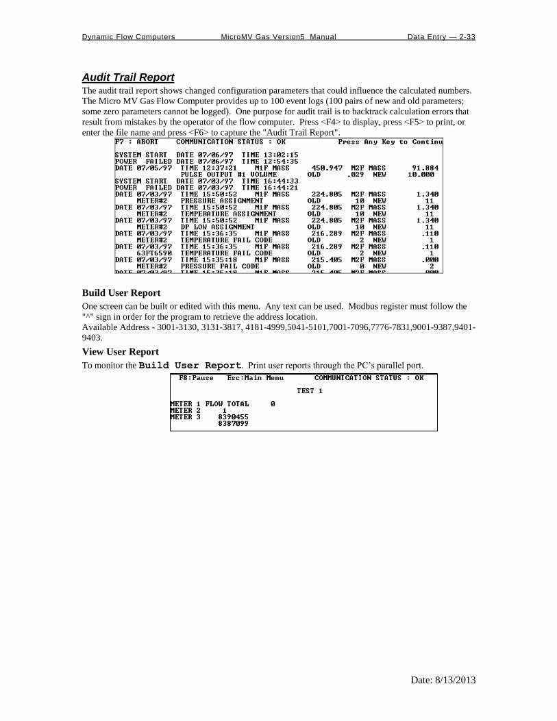
Dynamic Flow Computers MicroMV Gas Version5 Manual Data Entry — 2-33
Date: 8/13/2013
Audit Trail Report The audit trail report shows changed configuration parameters that could influence the calculated numbers.
The Micro MV Gas Flow Computer provides up to 100 event logs (100 pairs of new and old parameters;
some zero parameters cannot be logged). One purpose for audit trail is to backtrack calculation errors that
result from mistakes by the operator of the flow computer. Press <F4> to display, press <F5> to print, or
enter the file name and press <F6> to capture the "Audit Trail Report".
Build User Report
One screen can be built or edited with this menu. Any text can be used. Modbus register must follow the
"^" sign in order for the program to retrieve the address location.
Available Address - 3001-3130, 3131-3817, 4181-4999,5041-5101,7001-7096,7776-7831,9001-9387,9401-
9403.
View User Report
To monitor the Build User Report. Print user reports through the PC’s parallel port.

Dynamic Flow Computers MicroMV Gas Version5 Manual Data Entry — 2-34
Date: 8/13/2013
Build User Report One screen can be built or edited with this menu. Any text can be used. Modbus register must follow the
"^" sign in order for the program to retrieve the address location.
View User Report To monitor the Build User Report. User reports can be printed through the PC parallel port–see
Print | Files.
Formatted Ticket Report
The Micro MV Gas Flow Computer allow the user to make personal ticket report. This ticket report is just
for display and printing purposes. To make this report, user must use "Last Daily Data Area" in the Modbus
registers (3431-3703).
Example: DYNAMIC FLUID BATCH REPORT
METER 1 GROSS TOTAL ^3453
METER 1 MASS TOTAL ^3459
Results - The report will look as follows: DYNAMIC FLUID BATCH REPORT
METER 1 GROSS TOTAL 3000
METER 1 MASS TOTAL 1258
Ticket Report Select 0=Standard Report, 1=Format Ticket Report
Standard is the default report format that is programmed in the Micro MV Gas Flow Computer. Format is
according to the formatted daily report.
Capture File Name - capture that file under certain name.
Auto Data Retrieval This function is made to replace printers and use a PC to poll the configured units on time basis (Hourly or
Daily). All parameters polled will be stored in the configured file name. Each unit ID will have an
individual file name. The PC or laptop must be on at the time it has to get the data, and the user must
activate that function by pressing <F3> and leaving the PC on. The data format can be either standard or
user defined format. This function is to eliminate the need for paper and make the process more
environmentally friendly. Echo to the local printer can be enabled where reports will be stored on hard
drive and printed to a parallel printer.

Dynamic Flow Computers MicroMV Gas Version5 Manual Data Entry — 2-35
Date: 8/13/2013
Print "Help" File Turn on parallel printer, point the cursor to Help, press <ENTER>, and then press <F5> to print Help
file.
Print Modbus Registers Turn on parallel printer, point the cursor to Modbus Reg, press <ENTER>, and then press <F5> to print
Modbus registers.
Print Calibration Data Calibration data are programmed parameters in the data file. To print, turn on parallel printer, point the
cursor to the Calib.Data, press <ENTER>, and then press <F5>.
Print Files The user can print the files that were captured. Turn on parallel printer, point the cursor to the desired file,
and then press <ENTER>.

Dynamic Flow Computers MicroMV Gas Version5 Manual Data Entry — 3-1
Date: 8/13/2013
CHAPTER 3: Data Entry
Through Front Panel Display
The Data entry is a menu driven type construction.
Four Keys – ESC/Mode, Enter/Select, Down Arrow, Right Arrow
These keys can be used by using a reflective object. The reflective object must be placed in front of the key
to get a response.
Function
ESC/Mode Key
This key serves dual functions. In order to access the data entry, the mode key has to be activated. The
mode key is on/off type key. This key will get the security code prompt, and then using select, enter key
with the arrow keys to access the program. Place the reflective object on and then off for each step. Once
the data menu function access is completed, exit by using the escape key.
Select/Enter Key
It is used to stop screen from scrolling, to select data entry, and accept the data configurations. It
is on/off type key. Place the reflective object in front of key, and then move away before the next
step.
Down Arrow Key, Right Arrow Key
Scrolling keys, the Right Key function is to scroll right way for selecting the number to be
changed, and then changing the number by using Down Arrow Key
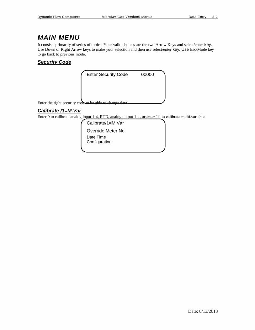
Dynamic Flow Computers MicroMV Gas Version5 Manual Data Entry — 3-2
Date: 8/13/2013
MAIN MENU It consists primarily of series of topics. Your valid choices are the two Arrow Keys and select/enter key.
Use Down or Right Arrow keys to make your selection and then use select/enter key. Use Esc/Mode key
to go back to previous mode.
Security Code
Enter Security Code 00000
Enter the right security code to be able to change data.
Calibrate /1=M.Var Enter 0 to calibrate analog input 1-4, RTD, analog output 1-4, or enter ‘1’ to calibrate multi.variable
Calibrate/1=M.Var
Override Meter No.
Date Time Configuration

Dynamic Flow Computers MicroMV Gas Version5 Manual Data Entry — 3-3
Date: 8/13/2013
Enable Calib. Mode
Analog Input (1-4)
RTD Input Analog Output (1-4)
Enable Calibrate Mode Enter ‘1’ to enable calibrate mode. Calibration mode will set the flow computer to continue totalizing at
same rate while all values are still showing live readings.
Calibrate Analog Input, RTD 0=Offset is a single point calibration that will offset zero and span.
1=Full – zero and span must be calibrated.
2=Reset to factory calibration.
0=Offset,1=Full
2=Reset
Offset (Single Point)
Induce the signal into the analog input, wait for 10 seconds for the reading to stabilize, then enter the offset.
Enter Offset 8.000
Current Value 7.9000

Dynamic Flow Computers MicroMV Gas Version5 Manual Data Entry — 3-4
Date: 8/13/2013
FULL (ZERO AND SPAN CALIBRATION )
1. Calibrate Low Point (4mA or 75 ,), induce the known live value for the low set point, and wait for 10
seconds for the reading to stabilize. Now enter in that value.
First Point 0.000
Current Value 0.9000
2. Calibrate High Point (20mA or 120 ), induce the known live value for the high set point, and then wait
for 10 seconds for the reading to stabilize. Now enter in that value.
Second Point 20.000
Current Value 19.900
Reset (Use Default )
Enter ‘2’ to use manufacture default.
Calibrate Analog Output 0=Offset is a single point calibration that will offset zero and span.
1=Full – zero and span must be calibrated.
2=Reset to factory calibration.
0=Offset,1=Full
2=Reset
Offset (Single Point)
Enter the live output value reading in the end device.
Enter mA 4.000
Reading mA 4.000
Full (Zero and Span Calibration)
1.The screen will show the minimum possible signal 4mA. Enter the live output value reading in the end
device i.e. 4mA.
Enter 4mA 4.000
Reading mA 4.000
2. Now the flow computer will output full scale 20mA. Enter the live output i.e. 20mA

Dynamic Flow Computers MicroMV Gas Version5 Manual Data Entry — 3-5
Date: 8/13/2013
Enter 20mA 20.000
Reading mA 20.000
Reset (Use Default )
Enter ‘2’ to use manufacture default.
Calibrate Multivariable Select DP, Pressure, or Temperature to be calibrated.
Calibrate Muli.Var.
DP Inches
Pressure PSIG Temperature DEG.F
Enter the calibrate method (0=Offset, 1=Full, 2=Reset).
0=Offset,1=Full
2=Reset
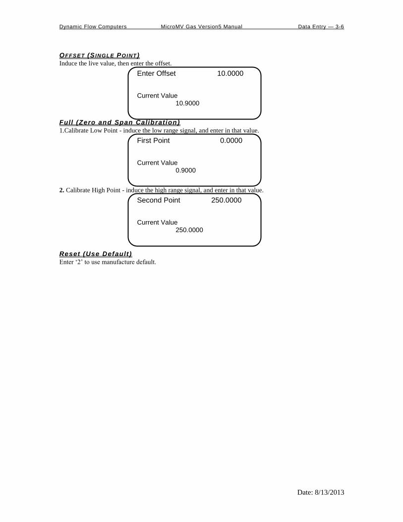
Dynamic Flow Computers MicroMV Gas Version5 Manual Data Entry — 3-6
Date: 8/13/2013
OFFSET (S INGLE POINT )
Induce the live value, then enter the offset.
Enter Offset 10.0000
Current Value 10.9000
Full (Zero and Span Calibration)
1.Calibrate Low Point - induce the low range signal, and enter in that value.
First Point 0.0000
Current Value 0.9000
2. Calibrate High Point - induce the high range signal, and enter in that value.
Second Point 250.0000
Current Value 250.0000
Reset (Use Default )
Enter ‘2’ to use manufacture default.

Dynamic Flow Computers MicroMV Gas Version5 Manual Data Entry — 3-7
Date: 8/13/2013
Override Meter No. Enter the meter number 1 or 2 to change meter override value
TF/PF/MF
HV/FPV
Dens.b/DCF Orifice/Pipe/DP
TF/PF/MF
TF - Temperature Deg.F
This value is entered when no live temperature is available, or when a different value from the live value
should be used.
PF – Pressure PSIG
This value is entered when no live temperature is available, or when a different value from the live value
should be used.
MF – Meter Factor
Enter the value to change current meter factor (AGA7 Method)
HV/FPV
Heating Value Override is used in the AGA8 calculation GROSS METHOD 1. In addition the heating
value totalizer requires the heating value; without a BTU override value entered, the Energy Flowrate will
always equal zero. Enter this number in BTU/SCF(standard cubic feet).
FPV override: used to enter a value to override the NX19 supercompressibility factor.
Dens.b/DCF
Base Density Override is used to override the calculated base density and affects the net calculations only.
For products other than natural gas, you must enter base density override for net calculations.
DCF- Density Correction Factor
Orif ice/Pipe/DP
Orifice ID in inches is the measured inside pipe diameter to 5 decimals at reference conditions
Pipe ID in inches is the measured diameter of the orifice at reference conditions.
DP Override in inches of water.
Date/Time
Change Date
Change Time
Change Date
Month 09
Day 08
Year 00 Change Date 1=Yes
Enter Month (1-12), Day (1-31), Year(0-99) and then enter ‘1’ to change date.

Dynamic Flow Computers MicroMV Gas Version5 Manual Data Entry — 3-8
Date: 8/13/2013
Change Time
Hour 09
Minute 08
Second 00 Change Time 1=Yes
Enter Hour (0-23), Minute (0-59), Second (0-59) and then enter ‘1’ to change time.

Dynamic Flow Computers MicroMV Gas Version5 Manual Data Entry — 3-9
Date: 8/13/2013
Configuration
Configuration
Configure Meter No 1
Configure I/O
Pulse Output Others
Configue Meter
Flow Equation 0-3 1
0=AGA3,1=New AGA3,
2=AGA7,3=Venturi
Flow Equation Type (0-3) 0 = AGA3 (OLD AGA3, 1985 Orifice Equations)
1 = API 14.3 (NEW AGA3, 1992 Orifice Equations)
2 = AGA7 (Frequency Type Input)
3 = Venturi

Dynamic Flow Computers MicroMV Gas Version5 Manual Data Entry — 3-10
Date: 8/13/2013
AGA3/New AGA3/Venturi
Orifice ID 10.00000
Pipe ID, 5.00000
DP Cut Off 1.0000 Viscosity .024500
Pipe I .D. Inches
Orif ice ID Inches
Pipe ID in inches is the measured inside pipe diameter to 5 decimals at reference conditions. Orifice ID in
inches is the measured diameter of the orifice at reference conditions.
DP Cutoff
The Micro MV Gas Flow Computer suspends all calculations whenever the DP, in inches of water column,
is less than this value. This function is vital for suppressing extraneous data when the DP transmitter drifts
around the zero mark under no-flow conditions.
Viscosity in Cent ipoise
Even though viscosity will shift with temperature and pressure changes, the effect on the calculations is
negligent. Therefore using a single value is appropriate in most cases. Enter viscosity in centipoise.

Dynamic Flow Computers MicroMV Gas Version5 Manual Data Entry — 3-11
Date: 8/13/2013
AGA7
K Factor 1000.000
Meter Factor 1.00000
Flow Cut Off Freq. 1
K FACTOR
K Factor is the number of pulses per unit volume, i.e. 1000 pulses/barrel. The tag on the meter would
normally indicate the K Factor.
Meter Factor
Meter Factor is a correction to the K Factor for this individual meter, applied multiplicatively to the K
factor.
FLOW CUTOFF FREQUENCY
The Smart Flow Computer will quit totalizing, when frequency is below the set limit. This feature is to
reduce noise effect when the meter is down for period of time. The totalizer will stop totalizing when the
frequency is below the cut off limit.
Configure I/O
Analog Output
Meter I/O
Status/Switch F.C.Display

Dynamic Flow Computers MicroMV Gas Version5 Manual Data Entry — 3-12
Date: 8/13/2013
Analog Output
Ana.Out#1 Assign 1
Ana.Out#2 Assign 0
Ana.Out#3 Assign 0 Ana.Out#4 Assign 0
ASSIGNMENTS :
4-20mA selection must be proportional and within the range of the selected parameter.
ASSIGNMENTS :
Meter 1 Meter 2 Station
Gross Flowrate 1 5 9
Net Flowrate 2 6 10
Mass Flowrate 3 7 11
Energy Flowrate 4 8 12
Meter 1
Meter2 Meter-Independent Parameters
DP 13 21 Spare #1 33
Temperature 14 22 Spare #2 34
Pressure 15 23 Remote Control* 35
Density 16 24
Examples:
9 = Station Gross Flowrate
30 = Meter 1 Specific Gravity
25 = Meter 2 Density Temperature
Density Temp 17 25
Dens.b 18 26
DP LOW 19 27
DP HIGH 20 28
Specific Gravity 30 32
Note: Assignments 29 and 31 are not used.
*Note : Remote control output can be controlled through the Modbus communication link.
Note: Dens.b = Base Density
DP = Differential Pressure
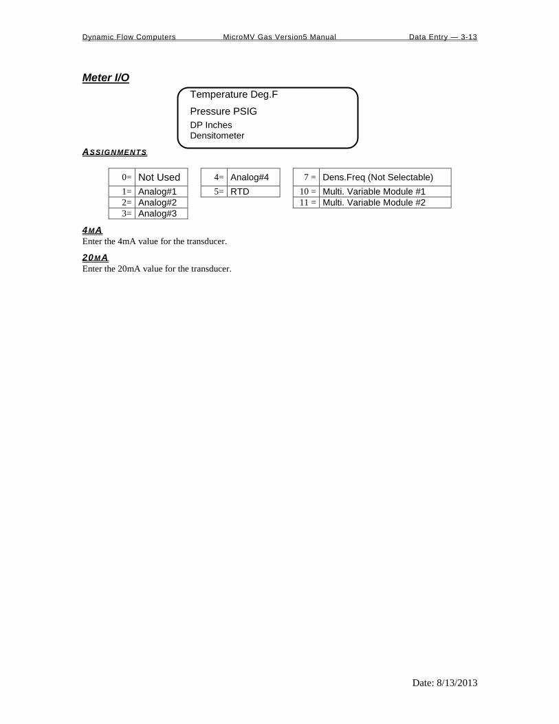
Dynamic Flow Computers MicroMV Gas Version5 Manual Data Entry — 3-13
Date: 8/13/2013
Meter I/O
Temperature Deg.F
Pressure PSIG
DP Inches Densitometer
ASSIGNMENTS
0= Not Used 4= Analog#4 7 = Dens.Freq (Not Selectable)
1= Analog#1 5= RTD 10 = Multi. Variable Module #1
2= Analog#2 11 = Multi. Variable Module #2
3= Analog#3
4MA
Enter the 4mA value for the transducer.
20MA
Enter the 20mA value for the transducer.

Dynamic Flow Computers MicroMV Gas Version5 Manual Data Entry — 3-14
Date: 8/13/2013
Status Input /Switch Output Assignment
Status/Switch#1 000
Status/Switch#2 001
Status/Switch#3 000 Status/Switch#4 000
Assignment Comments
1. N/A
2 Calibration Mode
3 Event Status
4. Alarm Acknowledge Reset the previous occurred alarms output bit
Switch Output Assignment User can assign an output to each of the Micro MV Gas Flow Computer’s output switches from this list.
The Micro MV Gas Flow Computer switch outputs are sourcing through switch power input power.
Outputs in the top list,”Pulse Outputs”, require a definition of pulse output per unit volume. Therefore a
Pulse Output Width must be defined when one of these switch types are chosen. These outputs are
available through swtiches 1 or 2 only.
Outputs in the bottom list,”Contact Type Outputs”, are ON/OFF type outputs. They can be assigned to any
of the four switch outputs.
Switches 1 and 2 can be pulse or contact type output; switches 3, 4 are contact-type output only.

Dynamic Flow Computers MicroMV Gas Version5 Manual Data Entry — 3-15
Date: 8/13/2013
Assignments - Pulse Outputs
Meter 1 Meter 2 Station
Gross 101 105 109
Net 102 106 110
Mass 103 107 111
Energy 104 108 112
ASSIGNMENTS - CONTACT TYPE OUTPUTS
Meter1 Meter2 Meter-Independent Parameters
Temperature Low 126 136 Day Ended 119
Temperature High 127 137 Dens. Period Low 146
Pressure Low 128 138 Dens. Period High 147
Pressure High 129 139 AGA8 Out of Range 148
Density Low 130 140 NX19 Out of Range 149
Density High 131 141 N/A 150
Dens.Temp Low 132 142 Active Alarms 151
Dens.Temp High 133 143 Occurred Alarms 152
DP Low 134 144 WatchDog 157
DP High 135 145 Remote Control 158
Meter Down 120 123 Run Switch 159
Flow Rate Low 121 124
Flow Rate High 122 125
N/A 153 155
N/A 154 156
Examples:
110= Station Net Flowrate (pulse output)
148= AGA8 out of Range

Dynamic Flow Computers MicroMV Gas Version5 Manual Data Entry — 3-16
Date: 8/13/2013
Flow Computer Display Assignment
FC.Display#1 000
FC.Display#2 001
FC.Display#3 000 FC.Display#4 000
Display assignment select up to 16 assignments. The Micro MV Gas Flow Computer will scroll through
them at the assigned delay time.
ASSIGNMENT
4 Digits – 1st
: Forward/Reverse – 0:Forward,1:Reverse
2nd
– Meter Number – 1:Meter#1, 2:Meter#2, 3:Station
3rd, 4th
: Selection
Selection 5. Description
01 Flow Rate
02 Daily Total
03 Cum. Total
04 Previous .Daily total
05 DP/DP Low, High
06 Temperature, Pressure
07 Density, Density at Base
08 Density Freq, Dens.Period, Un-Corr. Density
09 Density Temperature,Pressure
10 Flow and Density Calculation Type
11 Spare #1, Spare #2
12 Previous Day.AVG Temperature, Pressure, SG
13 Alarms
14 Date, Time
Examples:
101= Meter#1 Flowrate
102= Meter #1 Daily Total
302= Station Daily Total
113= Meter #1 Alarms
14= Date, Time
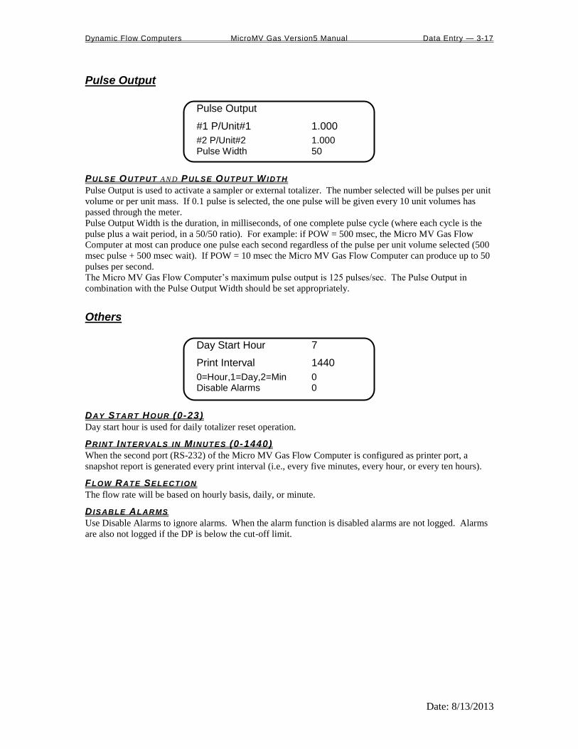
Dynamic Flow Computers MicroMV Gas Version5 Manual Data Entry — 3-17
Date: 8/13/2013
Pulse Output
Pulse Output
#1 P/Unit#1 1.000
#2 P/Unit#2 1.000 Pulse Width 50
PULSE OUTPUT AND PULSE OUTPUT W IDTH
Pulse Output is used to activate a sampler or external totalizer. The number selected will be pulses per unit
volume or per unit mass. If 0.1 pulse is selected, the one pulse will be given every 10 unit volumes has
passed through the meter.
Pulse Output Width is the duration, in milliseconds, of one complete pulse cycle (where each cycle is the
pulse plus a wait period, in a 50/50 ratio). For example: if POW = 500 msec, the Micro MV Gas Flow
Computer at most can produce one pulse each second regardless of the pulse per unit volume selected (500
msec pulse + 500 msec wait). If POW = 10 msec the Micro MV Gas Flow Computer can produce up to 50
pulses per second.
The Micro MV Gas Flow Computer’s maximum pulse output is 125 pulses/sec. The Pulse Output in
combination with the Pulse Output Width should be set appropriately.
Others
Day Start Hour 7
Print Interval 1440
0=Hour,1=Day,2=Min 0 Disable Alarms 0
DAY START HOUR (0-23)
Day start hour is used for daily totalizer reset operation.
PRINT INTERVALS IN M INUTES (0-1440)
When the second port (RS-232) of the Micro MV Gas Flow Computer is configured as printer port, a
snapshot report is generated every print interval (i.e., every five minutes, every hour, or every ten hours).
FLOW RATE SELECTION
The flow rate will be based on hourly basis, daily, or minute.
D ISABLE ALARMS
Use Disable Alarms to ignore alarms. When the alarm function is disabled alarms are not logged. Alarms
are also not logged if the DP is below the cut-off limit.

Dynamic Flow Computers MicroMV Gas Version5 Manual Flow Equations — 4-1
Date: 8/13/2013
CHAPTER 4: FLOW EQUATIONS
Common Terms The following terms are used throughout this chapter.
Term Definition Units Examples
q Flowrate: volume or mass displaced per unit
time See equations qmass , qenergy
T Temperature F unless noted
DP Differential Pressure across measuring device Inches H2O column
d Orifice Diameter Inches d , dr , dm
D Pipe Diameter Inches D , Dr , Dm
diameter Pipe
diameter Orifice
D
d Dimensionalless ratio , r
Density (usually of the fluid) Lb/ft3 flowing , m
Viscosity centipoise
HN Heating Value
Y Expansion factor Dimensionalless
Subscripts: Conventions Used
This Subscript Means Examples r At reference conditions Tr,p = reference temperature of the pipe
O (letter o) Refers to the orifice Tr,O = reference temperature of the orifice
P Refers to the pipe
flowing At flow conditions flowing = density at flow conditions
cal Calibration conditions Tcal , Pcal
m At measured conditions Dm = pipe diameter at measured temp.
Other Common Expressions For all equations,
MMBTU/Hr Flowrate Energy 310HNqnet

Dynamic Flow Computers MicroMV Gas Version5 Manual Flow Equations — 4-2
Date: 8/13/2013
AGA3 Please see Common Terms at the beginning of this chapter. For more information, please see AGA3
Publication.
dB
DPYdA
KBA
E4K
K
orifice the of eTemperatur ReferenceT
orificefor expansion of tCoefficien ThermalC
TTC1
Factor Expansion Thermal OrificeF
Where:
q
q
A FK
flowing
O,r
O
O,rflowingO
a
flowing
mass
reference
mass
a
4
2
20
0
10142974.7
099742275.0
2
)(
6.3
MCF/HrFlowrate Gross
MCF/Hr Flowrate Net
MLb/Hr
Flowrate Massmass
q

Dynamic Flow Computers MicroMV Gas Version5 Manual Flow Equations — 4-3
Date: 8/13/2013
API 14.3
For more information, please see Orifice Metering of Natural Gas, 3rd edition.
Mass Flow Rate = × × × × Y × × .001
Net Flow Rate =
Gross Flow Rate =
Energy Flow Rate = Net Flow Rate × Heating Value × .001
Where:
= Units Conversion Constant
= Orifice Plate Coefficient of Discharge
= = Velocity of Approach Factor
d = Orifice plate bore diameter
Y = Expansion Factor
DP = Orifice Differential Pressure
US unit
323.279
Density lb/
Gross Flow Rate/HR MCF
Net Flow Rate/HR MSCF
Mass Flow Rate/HR MLB
Energy Flow Rate/HR MMBTU

Dynamic Flow Computers MicroMV Gas Version5 Manual Flow Equations — 4-4
Date: 8/13/2013
AGA 7 Please see Common Terms at the beginning of this chapter.
Factor K NominalF
Factor LinearF
Factor MeterF
pulses/sec input, signalthe ofFrequency
q
q
F
FF
K
L
M
signal
flowinggross
reference
flowinggross
K
LMsignal
MCF/HrFlowrate Mass
MCF/Hr Flowrate Net
(MCF/Hr)Flowrate Grossgross
q
6.3

Dynamic Flow Computers MicroMV Gas Version5 Manual Flow Equations — 4-5
Date: 8/13/2013
Venturi Please see Common Terms at the beginning of this chapter. For further information please see
Measurement Engineering Handbook.
entry) (manual C tcoefficien DischargeC
Where
q
q
YdFCDP.
flowing
mass
reference
mass
aflowing
:
1
359072204
2
(MCF/HR) Flowrate Gross
(MCF/HR) Flowrate Net
(MLB/HR)
Flowrate Mass
massq

Dynamic Flow Computers MicroMV Gas Version5 Manual Flow Equations — 4-6
Date: 8/13/2013
DENSITY EQUATIONS
Sarasota Density GM/CC Sarasota density is calculated using the frequency signal produced by a Sarasota densitometer, and applying
temperature and pressure corrections as shown below.
Gure in PSItion press = CalibraP
ds/PSIGmicrosecon in tcoefficien Pressure = P
in PSIGg pressureP = Flowin
F/dsmicroseconicient in ture coeff = TemperaT
dsmicrosecon in constant ncalibratio A =
.dsmicroseconeriod in illation pometer osct = Densit
gm/cm e,mass/volum constant, nCalibratio= D
rtion Factoity CorrecDCF = Dens
) + T (P - P ) + P (T - T = TT
Where
T
t-T +K T
t-TD DCF
cal
coef
coef
t
3
calcoefcalcoefp
p
pp
p
0
0
00
0
00
00
:
2
)(1
)(2 = Density Corrected
UGC Density GM/CC UGC density is calculated using the frequency signal produced by a UGC densitometer, and applying
temperature and pressure corrections as shown below
F/dsmicrosecon in tcoefficien eTemperatur = T
icientture Coeff = TemperaK
Offset Pressure = P
Constant PressureK =
rtion Factoity CorrecDCF = Dens
dsmicrosecon in period noscillatioer Densitomett =
Constants nCalibratio= , K, KK
tt + K + Kd = K
Where
+ d-TTK++dPKP= DCF
cal
T
off
calflowingT-
offflowing
210
2210
(6
:
})][]10)({[ Density Corrected

Dynamic Flow Computers MicroMV Gas Version5 Manual Flow Equations — 4-7
Date: 8/13/2013
Solartron Density GM/CC Solartron density is calculated using the frequency signal produced by a Solartron densitometer, and
applying temperature and pressure corrections as shown below.
DENSITY AT 20 DEG .C AND 0 BAR
onby Solartr SuppliedConstants nCalibratio =K ,K ,K
dsmicrosecon in Period nOscillatioer Densitomet = t
:Where
tK + tK K=D
210
2210 +
TEMPERATURE CORRECTED DENSITY
)]20()20(1[ 1918 TKTKD = DT
ADDIT IONAL EQUATION FOR GAS OFFSET DATA
The following equation can provide more accurate measurement for Argon/Methane Gas Mixture over
density range 60 to 200 kg/m3.
))273/(00236.0)4/(31( TGxKDTKDTDA
G = Gas Specific Gravity / Ratio of Specific Heats.
Density (GM/CC)= Density(KG/M3) / 1000.0

Dynamic Flow Computers MicroMV Gas Version5 Manual Flow Equations — 4-8
Date: 8/13/2013
AGA8 Gross Method 1
Refer to Transmission Measurement Committee Report No. 8
AGA8 Gross Method 2 Refer to Transmission Measurement Committee Report No. 8
AGA8 Detail Method Refer to Transmission Measurement Committee Report No. 8

Dynamic Flow Computers MicroMV Gas Version5 Manual Modbus Data — 5-1
Date: 8/13/2013
CHAPTER 5: MODBUS DATA
MODBUS PROTOCOL
TRANSMISSION MODE
ASCII RTU
DATA BITS 7 8
START BITS 1 1
PARITY EVEN,ODD NONE
STOP BITS 1 1
ERROR CHECKING LRC CRC
BAUD RATE 1200-9600 1200-9600
ASCII FRAMING Framing is accomplished by using colon (:) character indicating the beginning of frame and carriage (CR),
line feed (LF) for the end of frame
ASCII MESSAGE FORMAT ADDRESS FUNCTION DATA ERR\CHECK
: 2 CHAR 2 CHAR Nx2 CHAR 2 CHAR CR LF
8 BITS 16 BITS 16 BITS Nx16 BITS 16 BITS 8 BITS 8 BITS
RTU FRAMING Frame synchronization is done by time basis only. The Smart Flow Computer allows 3.5 characters time
without new characters coming in before proceeding to process the message and resetting the buffer.
RTU MESSAGE FORMAT ADDRESS FUNCTION DATA CRC
8 BITS 8 BITS Nx8 BITS 16 BITS

Dynamic Flow Computers MicroMV Gas Version5 Manual Modbus Data — 5-2
Date: 8/13/2013
FUNCTION CODE To inform the slave device of what function to perform
FUNCTION CODE
ACTION
01
03 Read Strings or Multiple 16 Bits
16 Write Strings or Multiple 16 Bits
ERROR CHECK
LRC MODE
The LRC check is transmitted as two ASCII hexadecimal characters. First, the message has to be stripped
of the :, LF, CR, and then converted the HEX ASCII to Binary. Add the Binary bits and then two's
complement the result.
CRC MODE
The entire message is considered in the CRC mode. Most significant bit is transmitted first. The message is
pre-multiplied by 16. The integer quotient digits are ignored and the 16-bit remainder is appended to the
message as the two CRC check bytes. The resulting message including the CRC, when divided by the
same polynomial (X16+X15+X2+1) at the receiver which will give zero remainder if no error has occurred.
EXCEPTION RESPONSE Exception response comes from the slave if it finds errors in communication. The slave responds to the
master echoing the slave address, function code (with high bit set), exception code and error check. To
indicate that the response is notification of an error, the high order bit of the function code is set to 1.
EXCEPTION CODE DESCRIPTION
01 Illegal Function
02 Illegal Data Address
03 Illegal Data Value
BROADCAST COMMAND All units listen to Unit ID Zero, and none will respond when that write function is broadcasted.

Dynamic Flow Computers MicroMV Gas Version5 Manual Modbus Data — 5-3
Date: 8/13/2013
MODBUS EXAMPLES
FUNCTION CODE 03 (Read Single or Multiple Register Points)
RTU MODE - Read Address 3076
ADDR FUNC CODE
STARTING POINT # OF POINTS CRC CHECK
HI LO HI LO
01 03 0C 04 00 01 C6 9B
Response
ADDR FUNC CODE
BYTE COUNTS
DATA CRC CHECK
HI LO
01 03 02 00 01 79 84
Write Address 3076
ADDR FUNC CODE
START POINT
# OF POINTS
BYTE COUNTS
DATA CRC CHECK
HI LO HI LO HI LO
01 10 0C 04 00 01 02 00 01 AA 14
Response
ADDR FUNC CODE
START ADDR
# OF POINTS
CRC CHECK
C 10 0C 04 01 43 58
ASCII MODE - Read Address 3076
ADDR FUNC CODE
STARTING POINT # OF POINTS LRC CHECK
HI LO HI LO
: 30 31 30 33 30 43 30 43 30 30 30 31 45 42 CR LF
Response
ADDR FUNC CODE
BYTE COUNT
DATA LRC CHECK
HI LO
: 30 31 30 33 30 32 30 30 30 31 46 39 CR LF
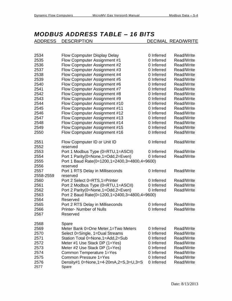
Dynamic Flow Computers MicroMV Gas Version5 Manual Modbus Data – 5-4
Date: 8/13/2013
MODBUS ADDRESS TABLE – 16 BITS ADDRESS DESCRIPTION DECIMAL READ/WRITE
2534 Flow Copmputer Display Delay 0 Inferred Read/Write 2535 Flow Copmputer Assignment #1 0 Inferred Read/Write 2536 Flow Copmputer Assignment #2 0 Inferred Read/Write 2537 Flow Copmputer Assignment #3 0 Inferred Read/Write 2538 Flow Copmputer Assignment #4 0 Inferred Read/Write 2539 Flow Copmputer Assignment #5 0 Inferred Read/Write 2540 Flow Copmputer Assignment #6 0 Inferred Read/Write 2541 Flow Copmputer Assignment #7 0 Inferred Read/Write 2542 Flow Copmputer Assignment #8 0 Inferred Read/Write 2543 Flow Copmputer Assignment #9 0 Inferred Read/Write 2544 Flow Copmputer Assignment #10 0 Inferred Read/Write 2545 Flow Copmputer Assignment #11 0 Inferred Read/Write 2546 Flow Copmputer Assignment #12 0 Inferred Read/Write 2547 Flow Copmputer Assignment #13 0 Inferred Read/Write 2548 Flow Copmputer Assignment #14 0 Inferred Read/Write 2549 Flow Copmputer Assignment #15 0 Inferred Read/Write 2550 Flow Copmputer Assignment #16 0 Inferred Read/Write 2551 Flow Copmputer ID or Unit ID 0 Inferred Read/Write 2552 reserved 2553 Port 1 Modbus Type (0=RTU,1=ASCII) 0 Inferred Read/Write 2554 Port 1 Parity(0=None,1=Odd,2=Even) 0 Inferred Read/Write 2555 Port 1 Baud Rate(0=1200,1=2400,3=4800,4=9600) 2556 reserved 2557 Port 1 RTS Delay in Milliseconds 0 Inferred Read/Write 2558-2559 reserved 2560 Port 2 Select 0=RTS,1=Printer 0 Inferred Read/Write 2561 Port 2 Modbus Type (0=RTU,1=ASCII) 0 Inferred Read/Write 2562 Port 2 Parity(0=None,1=Odd,2=Even) 0 Inferred Read/Write 2563 Port 2 Baud Rate(0=1200,1=2400,3=4800,4=9600) 2564 Reserved 2565 Port 2 RTS Delay in Milliseconds 0 Inferred Read/Write 2566 Printer- Number of Nulls 0 Inferred Read/Write 2567 Reserved 2568 Spare 2569 Meter Bank 0=One Meter,1=Two Meters 0 Inferred Read/Write 2570 Select 0=Single, 1=Dual Streams 0 Inferred Read/Write 2571 Station Total 0=None,1=Add,2=Sub 0 Inferred Read/Write 2572 Meter #1 Use Stack DP (1=Yes) 0 Inferred Read/Write 2573 Meter #2 Use Stack DP (1=Yes) 0 Inferred Read/Write 2574 Common Temperature 1=Yes 0 Inferred Read/Write 2575 Common Pressure 1=Yes 0 Inferred Read/Write 2576 Density#1 0=None,1=4-20mA,2=S,3=U,3=S 0 Inferred Read/Write 2577 Spare

Dynamic Flow Computers MicroMV Gas Version5 Manual Modbus Data – 5-5
Date: 8/13/2013
2578 Use Meter Temp as Dens.Temp#1 0=N,1=Y 0 Inferred Read/Write 2579 Spare 2580 Common Density 1=Yes 0 Inferred Read/Write 2581 Density#2 0=None,1=4-20mA,2=S,3=U,3=S 0 Inferred Read/Write 2582 Spare 2583 Use Meter Temp#2 as Dens.Temp 1=Yes 0 Inferred Read/Write 2584 Spare 2585-2592 Reserved 2593 Flow Rate Display 0=Hour,1=Day,2=Minute 0 Inferred Read/Write 2594 Flowrate Averaged Seconds (1-10) 0 Inferred Read/Write 2595 Day Start Hour (0-23) 0 Inferred Read/Write 2596-2605 Company Name 40 Chars Read/Write 2606 Disable Alarms ? (0=No, 1=Yes) 0 Inferred Read/Write 2607 Print Interval in Minutes (0-1440) 0 Inferred Read/Write 2608 Run Switch Delay 0 Inferred Read/Write 2609 Pulse Width 0 Inferred Read/Write 2610-2612 Spare 2613-2616 Spare 2617 Status Input/Switch Output #1 (0=OFF,1=ON) 0 Inferred Read/Write 2618 Status Input/Switch Output #2 (0=OFF,1=ON) 0 Inferred Read/Write 2619 Status Input/Switch Output #3 (0=OFF,1=ON) 0 Inferred Read/Write 2620 Status Input/Switch Output #4 (0=OFF,1=ON) 0 Inferred Read/Write 2621 Spare 2622 Meter #1 Flow Cut Off Freq. (0-99) 0 Inferred Read/Write 2623 Meter #2 Flow Cut Off Freq. (0-99) 0 Inferred Read/Write 2624-2633 Meter Location 40 Chars. Read/Write 2634-2637 Meter #1 ID 8 Chars. Read/Write 2638 Meter#1 Density Calction Type 0 Inferred Read/Write 2639 Spare 2640-2643 Meter #2 ID 8 Chars. Read/Write 2644 Meter#2 Density Calction Type 0 Inferred Read/Write 2645-2646 reserved 2647 Meter #1 AGA7 Select Mass Pulses (1=Yes) 0 Inferred Read/Write 2648 Meter #2 AGA7 Select Mass Pulses (1=Yes) 0 Inferred Read/Write 2649-2651 Reserved 2652-2797 Sapre 2798 Meter #1 DP Low Assignment 0 Inferred Read/Write 2799 Meter #1 Temperature Assignment 0 Inferred Read/Write 2800 Meter #1 Pressure Assignment 0 Inferred Read/Write 2801 Meter #1 Density Assignment 0 Inferred Read/Write 2802 Meter #1 Density Temp. Assignment 0 Inferred Read/Write 2803 Meter #1 DP High Assignment 0 Inferred Read/Write 2804 Meter #2 DP Low Assignment 0 Inferred Read/Write 2805 Meter #2 Temperature Assignment 0 Inferred Read/Write 2806 Meter #2 Pressure Assignment 0 Inferred Read/Write 2807 Meter #2 Density Assignment 0 Inferred Read/Write 2808 Meter #2 Density Temp. Assignment 0 Inferred Read/Write
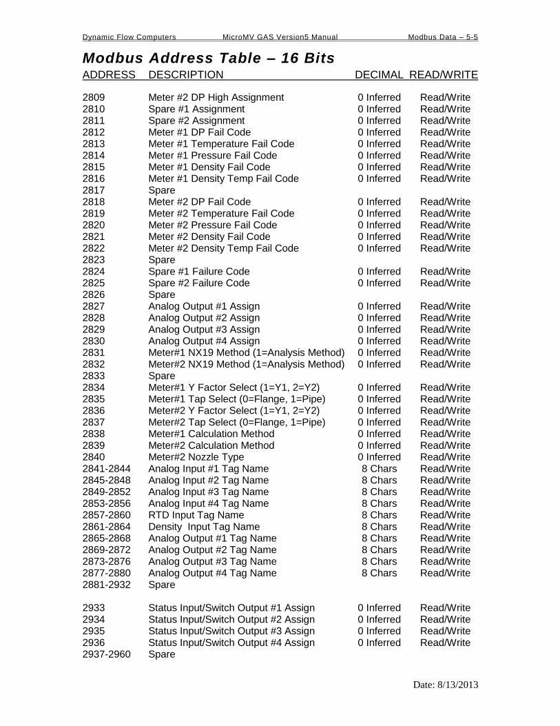
Dynamic Flow Computers MicroMV GAS Version5 Manual Modbus Data – 5-5
Modbus Address Table – 16 Bits ADDRESS DESCRIPTION DECIMAL READ/WRITE
Date: 8/13/2013
2809 Meter #2 DP High Assignment 0 Inferred Read/Write 2810 Spare #1 Assignment 0 Inferred Read/Write 2811 Spare #2 Assignment 0 Inferred Read/Write 2812 Meter #1 DP Fail Code 0 Inferred Read/Write 2813 Meter #1 Temperature Fail Code 0 Inferred Read/Write 2814 Meter #1 Pressure Fail Code 0 Inferred Read/Write 2815 Meter #1 Density Fail Code 0 Inferred Read/Write 2816 Meter #1 Density Temp Fail Code 0 Inferred Read/Write 2817 Spare 2818 Meter #2 DP Fail Code 0 Inferred Read/Write 2819 Meter #2 Temperature Fail Code 0 Inferred Read/Write 2820 Meter #2 Pressure Fail Code 0 Inferred Read/Write 2821 Meter #2 Density Fail Code 0 Inferred Read/Write 2822 Meter #2 Density Temp Fail Code 0 Inferred Read/Write 2823 Spare 2824 Spare #1 Failure Code 0 Inferred Read/Write 2825 Spare #2 Failure Code 0 Inferred Read/Write 2826 Spare 2827 Analog Output #1 Assign 0 Inferred Read/Write 2828 Analog Output #2 Assign 0 Inferred Read/Write 2829 Analog Output #3 Assign 0 Inferred Read/Write 2830 Analog Output #4 Assign 0 Inferred Read/Write 2831 Meter#1 NX19 Method (1=Analysis Method) 0 Inferred Read/Write 2832 Meter#2 NX19 Method (1=Analysis Method) 0 Inferred Read/Write 2833 Spare 2834 Meter#1 Y Factor Select (1=Y1, 2=Y2) 0 Inferred Read/Write 2835 Meter#1 Tap Select (0=Flange, 1=Pipe) 0 Inferred Read/Write 2836 Meter#2 Y Factor Select (1=Y1, 2=Y2) 0 Inferred Read/Write 2837 Meter#2 Tap Select (0=Flange, 1=Pipe) 0 Inferred Read/Write 2838 Meter#1 Calculation Method 0 Inferred Read/Write 2839 Meter#2 Calculation Method 0 Inferred Read/Write 2840 Meter#2 Nozzle Type 0 Inferred Read/Write 2841-2844 Analog Input #1 Tag Name 8 Chars Read/Write 2845-2848 Analog Input #2 Tag Name 8 Chars Read/Write 2849-2852 Analog Input #3 Tag Name 8 Chars Read/Write 2853-2856 Analog Input #4 Tag Name 8 Chars Read/Write 2857-2860 RTD Input Tag Name 8 Chars Read/Write 2861-2864 Density Input Tag Name 8 Chars Read/Write 2865-2868 Analog Output #1 Tag Name 8 Chars Read/Write 2869-2872 Analog Output #2 Tag Name 8 Chars Read/Write 2873-2876 Analog Output #3 Tag Name 8 Chars Read/Write 2877-2880 Analog Output #4 Tag Name 8 Chars Read/Write 2881-2932 Spare 2933 Status Input/Switch Output #1 Assign 0 Inferred Read/Write 2934 Status Input/Switch Output #2 Assign 0 Inferred Read/Write 2935 Status Input/Switch Output #3 Assign 0 Inferred Read/Write 2936 Status Input/Switch Output #4 Assign 0 Inferred Read/Write 2937-2960 Spare

Dynamic Flow Computers MicroMV GAS Version5 Manual Modbus Data – 5-6
Modbus Address Table – 16 Bits ADDRESS DESCRIPTION DECIMAL READ/WRITE
Date: 8/13/2013
2961-2964 Multi.Var.#1 DP Tag 8 Chars. Read/Write 2965-2968 Multi.Var.#1 Pressure Tag 8 Chars. Read/Write 2969-2972 Multi.Var.#1 Temperature Tag 8 Chars. Read/Write 2973-2976 Multi.Var.#2 DP Tag 8 Chars. Read/Write 2977-2980 Multi.Var.#2 Pressure Tag 8 Chars. Read/Write 2981-2984 Multi.Var.#2 Temperature Tag 8 Chars. Read/Write 2985 Analog Output#1 –Remote Control (0-100) 0 Inferred Read/Write 2986 Analog Output#2 –Remote Control (0-100) 0 Inferred Read/Write 2987 Analog Output#3 –Remote Control (0-100) 0 Inferred Read/Write 2988 Analog Output#4 –Remote Control (0-100) 0 Inferred Read/Write

Dynamic Flow Computers MicroMV GAS Version5 Manual Modbus Data – 5-7
Modbus Address Table – 16 Bits ADDRESS DESCRIPTION DECIMAL READ/WRITE
Date: 8/13/2013
3001 Version Number 2 Inferred Read 3002-3006 Spare 3007 Meter #1 Product Used 0 Inferred Read 3008-3011 Meter #1 ID 8 Chars Read 3012 Spare 3013 Meter #2 Product Used 0 Inferred Read 3014-3017 Meter #2 ID 8 Chars Read 3018 Flow Computer Unit Number 0 Inferred Read 3019 Disable Alarms (1=Yes) 0 Inferred Read 3020-3023 Spare 3024 Enable Calibration Mode (1=Yes) 0 Inferred Read 3025 Calibration – Set Time (1-9 Hours) 0 Inferred Read 3026 Last Daily Report Request (1=Latest,35=Oldest) 0 Inferred Read/Write Daily Data Area in Location 3431-3753 3027 Last Monthly Report Request(1=Latest,12=Oldest) 0 Inferred Read/Write Set Last Monthly Report Request to 1 Monthly Data Area in Location 3431-3753 3028 Last Hourly Report Request – Starting Hour 0 Inferred Read/Write 3029 Last Hourly Report Request 0 Inferred Read/Write 3030 Last Alarm Report Request 0 Inferred Read/Write 3031 Last Audt Report Request 0 Inferred Read/Write

Dynamic Flow Computers MicroMV GAS Version5 Manual Modbus Data – 5-8
Modbus Address Table – 16 Bits ADDRESS DESCRIPTION DECIMAL READ/WRITE
Date: 8/13/2013
Scaled Data Area
3032 Meter #1 Gross Flowrate 0 Inferred Read 3033 Meter #1 Net Flowrate 0 Inferred Read 3034 Meter #1 Mass Flowrate 0 Inferred Read 3035 Meter #1 Energy Flowrate 0 Inferred Read 3036-3043 Spare 3044 Meter #2 Gross Flowrate 0 Inferred Read 3045 Meter #2 Net Flowrate 0 Inferred Read 3046 Meter #2 Mass Flowrate 0 Inferred Read 3047 Meter #2 Energy Flowrate 0 Inferred Read 3048-3055 Spare 3056 Spare #1 Data 0 Inferred Read 3057 Spare #2 Data 0 Inferred Read 3058 Meter #1 DP 0 Inferred Read 3059 Meter #1 Temperature 0 Inferred Read 3060 Meter #1 Pressure 0 Inferred Read 3061 Meter #1 Density 0 Inferred Read 3062 Meter #1 Dens.Temperature 0 Inferred Read 3063 Meter #2 DP 0 Inferred Read 3064 Meter #2 Temperature 0 Inferred Read 3065 Meter #2 Pressure 0 Inferred Read 3066 Meter #2 Density 0 Inferred Read 3067 Meter #2 Dens.Temperature 0 Inferred Read
SCALED DATA AREA ENDS
3123 Retrieve History Data ACK Flag 0 Inferred Read/Write
Modbus 16-bit Address Table Ends

Dynamic Flow Computers MicroMV Gas Version5 Manual Modbus Data – 5-9
Modbus Address Table – 32 Bits ADDRESS DESCRIPTION DECIMAL READ/WRITE
Date: 8/13/2013
*Non-resettable accumulated volume will roll over at 9999999.
3131 Meter #1 Gross Flowrate 2 inferred Read 3133 Meter #1 Net Flowrate 2 inferred Read 3135 Meter #1 Mass Flowrate 2 inferred Read 3137 Meter #1 Energy Flowrate 2 inferred Read 3139 Meter #1 DP Low 4 Inferred Read 3141 Meter #1 DP High 4 Inferred Read 3143 Meter #1 DP 4 Inferred Read 3145 Meter #1 Temperature 1 Inferred Read 3147 Meter #1 Pressure 1 Inferred Read 3149 Meter #1 Density 6 Inferred Read 3151 Meter #1 Density Temperature 1 Inferred Read 3153 Meter #1 Density.b 6 Inferred Read 3155 Meter #1 SG 6 Inferred Read 3157 Meter #1 Y Factor 6 Inferred Read 3159 Meter #1 K/CD/LMF 6 Inferred Read 3161 Meter #1 FA 6 Inferred Read 3163 Meter #1 FPV/FRA 6 Inferred Read 3165 Meter #1 Meter Factor 6 Inferred Read 3167 Meter #1 Linear Factor 6 Inferred Read 3169-3171 Spare 3173 Meter #1 Daily Gross Total 0 inferred Read 3175 Meter #1 Daily Net Total 0 inferred Read 3177 Meter #1 Daily Mass Total 0 Inferred Read 3179 Meter #1 Daily Energy Total 0 Inferred Read 3181 Meter #1 Cumulative Gross Total* 0 Inferred Read 3183 Meter #1 Cumulative Net Total* 0 Inferred Read 3185 Meter #1 Cumulative Mass Total* 0 Inferred Read 3187 Meter #1 Cumulative Energy Total* 0 Inferred Read 3189-3203 Spare 3205 Meter #2 Gross Flowrate 2 Inferred Read 3207 Meter #2 Net Flowrate 2 Inferred Read 3209 Meter #2 Mass Flowrate 2 Inferred Read 3211 Meter #2 Energy Flowrate 2 Inferred Read 3213 Meter #2 DP Low 4 Inferred Read 3215 Meter #2 DP High 4 Inferred Read 3217 Meter #2 DP 4 Inferred Read 3219 Meter #2 Temperature 1 Inferred Read 3221 Meter #2 Pressure 1 Inferred Read

Dynamic Flow Computers MicroMV Gas Version5 Manual Modbus Data – 5-10
Modbus Address Table – 32 Bits ADDRESS DESCRIPTION DECIMAL READ/WRITE
Date: 8/13/2013
3223 Meter #2 Density 6 Inferred Read 3225 Meter #2 Density Temperature 1 Inferred Read 3227 Meter #2 Density.b 6 Inferred Read 3229 Meter #2 SG 6 Inferred Read 3231 Meter #2 Y Factor 6 Inferred Read 3233 Meter #2 K/CD/LMF 6 Inferred Read 3235 Meter #2 FA 6 Inferred Read 3237 Meter #2 FPV/FRA 6 Inferred Read 3239 Meter #2 Meter Factor 6 Inferred Read 3241 Meter #2 Linear Factor 6 Inferred Read 3243-3245 Spare 3247 Meter #2 Daily Gross Total 0 Inferred Read 3249 Meter #2 Daily Net Total 0 Inferred Read 3251 Meter #2 Daily Mass Total 0 Inferred Read 3253 Meter #2 Daily Energy Total 0 Inferred Read 3255 Meter #2 Cumulative Gross Total* 0 Inferred Read 3257 Meter #2 Cumulative Net Total* 0 Inferred Read 3259 Meter #2 Cumulative Mass Total* 0 Inferred Read 3261 Meter #2 Cumulative Energy Total* 0 Inferred Read 3263-3277 Spare 3279 Station Gross Flowrate 2 Inferred Read 3281 Station Net Flowrate 2 Inferred Read 3283 Station Mass Flowrate 2 Inferred Read 3285 Station Energy Flowrate 2 Inferred Read 3287 Station Daily Gross Total 0 Inferred Read 3289 Station Daily Net Total 0 Inferred Read 3291 Station Daily Mass Total 0 Inferred Read 3293 Station Daily. Energy Total 0 Inferred Read 3295 Station Cum. Gross Total 0 Inferred Read 3297 Station Cum. Net Total 0 Inferred Read 3299 Station Cum. Mass Total 0 Inferred Read 3301 Station Cum. Energy Total 0 Inferred Read 3303-3317 Spare 3319 Meter #1 Hourly Gross Total 0 Inferred Read 3321 Meter #1 Hourly Net Total 0 Inferred Read 3323 Meter #1 Hourly Mass Total 0 Inferred Read 3325 Meter #1 Hourly Energy Total 0 Inferred Read 3327-3333 Spare 3335 Meter #2 Hourly Gross Total 0 Inferred Read 3337 Meter #2 Hourly Net Total 0 Inferred Read 3339 Meter #2 Hourly Mass Total 0 Inferred Read 3341 Meter #2 Hourly Energy Total 0 Inferred Read 3343-3349 Spare 3351 Meter #1 Monthly Gross Total 0 Inferred Read 3353 Meter #1 Monthly Net Total 0 Inferred Read

Dynamic Flow Computers MicroMV Gas Version5 Manual Modbus Data – 5-11
Modbus Address Table – 32 Bits ADDRESS DESCRIPTION DECIMAL READ/WRITE
Date: 8/13/2013
3353 Meter #1 Monthly Net Total 0 Inferred Read 3355 Meter #1 Monthly Mass Total 0 Inferred Read 3357 Meter #1 Monthly Energy Total 0 Inferred Read 3359-3365 Spare 3367 Meter #2 Monthly Gross Total 0 Inferred Read 3369 Meter #2 Monthly Net Total 0 Inferred Read 3371 Meter #2 Monthly Mass Total 0 Inferred Read 3373 Meter #2 Monthly Energy Total 0 Inferred Read 3375-3381 Spare 3383 Spare #1 4 Inferred Read 3385 Spare #2 4 Inferred. Read 3387 Analog Output #1 Output % 2 Inferred Read 3389 Analog Output #2 Output % 2 Inferred Read 3391 Meter #1 Uncorrected Density 6 Inferred Read 3393 Meter #2 Uncorrected Density 6 Inferred Read 3395-3429 Spare

Dynamic Flow Computers MicroMV Gas Version5 Manual Modbus Data – 5-12
Modbus Address Table – 32 Bits ADDRESS DESCRIPTION DECIMAL READ/WRITE
Date: 8/13/2013
Last Daily or Monthly Data Area
Set Last Daily Report Request (3026) to 1=Latest,32=Oldtest Daily Data Area in Location 3431-3753 Set Last Monthly Report Request (3027) to 1=Latest,12=Oldtest Monthly Data Area in Location 3431-3753 3431 Batch Type/Disp/Bank/Station Flag 0 Inferred Read 3433 Day/Month Start Date 0 Inferred Read 3435 Day/Month Start Time 0 Inferred Read 3437 Meter#1 ID 8 Chars. Read 3439 Meter#2 ID 8 Chars. Read 3441 Meter#1 Flowing Times 1 Inferred Read 3443 Meter #1 Gross Total 0 Inferred Read 3445 Meter #1 Net Total 0 Inferred Read 3447 Meter #1 Mass Total 0 Inferred Read 3449 Meter #1 Energy Total 0 Inferred Read 3451 Meter #1 Average DP 4 Inferred Read 3453 Meter #1 Average Temperature 1 Inferred Read 3455 Meter #1 Average Pressure 1 Inferred Read 3457 Meter #1 Average DP_EXT 4 Inferred Read 3459 Meter #1 Average Heating Value 3 Inferred Read 3461 Meter #1 Average SG 6 Inferred Read 3473 Meter #1 Average N2 4 Inferred Read 3475 Meter #1 Average CO2 4 Inferred Read 3477 Meter #1 Average Methane 4 Inferred Read 3479 Meter #1 Average Ethane 4 Inferred Read 3481 Meter #1 Average Propane 4 Inferred Read 3483 Meter #1 Average Water 4 Inferred Read 3485 Meter #1 Average H2S 4 Inferred Read 3487 Meter #1 Average H2 4 Inferred Read 3489 Meter #1 Average CO 4 Inferred Read 3481 Meter #1 Average Oxygen 4 Inferred Read 3483 Meter #1 Average i-Butane 4 Inferred Read 3485 Meter #1 Average n-Butane 4 Inferred Read 3487 Meter #1 Average i-Pentane 4 Inferred Read 3489 Meter #1 Average n-Pentane 4 Inferred Read 3491 Meter #1 Average n-Hexane 4 Inferred Read 3493 Meter #1 Average n-Heptane 4 Inferred Read 3495 Meter #1 Average n-Octane 4 Inferred Read 3497 Meter #1 Average n-Nonane 4 Inferred Read 3499 Meter #1 Average n-Decane 4 Inferred Read 3501 Meter #1 Average Helium 4 Inferred Read 3503 Meter #1 Average Argon 4 Inferred Read 3505-3567 Spare

Dynamic Flow Computers MicroMV Gas Version5 Manual Modbus Data – 5-13
Modbus Address Table – 32 Bits ADDRESS DESCRIPTION DECIMAL READ/WRITE
Date: 8/13/2013
3569-3571 Meter#2 ID 8 Chars Read 3573 Meter#2 Flowing Times 0 Inferred Read 3575 Meter#2 Gross Total 0 Inferred Read 3577 Meter #2 Net Total 0 Inferred Read 3579 Meter #2 Mass Total 0 Inferred Read 3581 Meter #2 Energy Total 0 Inferred Read 3583 Meter #2 Average DP 4 Inferred Read 3585 Meter #2 Average Temperature 1 Inferred Read 3587 Meter #2 Average Pressure 1 Inferred Read 3589 Meter #2 Average DP_EXT 4 Inferred Read 3591 Meter #2 Average Heating Value 3 Inferred Read 3593 Meter #2 Average SG 6 Inferred Read 3595 Meter #2 Average N2 4 Inferred Read 3597 Meter #2 Average CO2 4 Inferred Read 3599 Meter #2 Average Methane 4 Inferred Read 3601 Meter #2 Average Ethane 4 Inferred Read 3603 Meter #2 Average Propane 4 Inferred Read 3605 Meter #2 Average Water 4 Inferred Read 3607 Meter #2 Average H2S 4 Inferred Read 3609 Meter #2 Average H2 4 Inferred Read 3611 Meter #2 Average CO 4 Inferred Read 3613 Meter #2 Average Oxygen 4 Inferred Read 3615 Meter #2 Average i-Butane 4 Inferred Read 3617 Meter #2 Average n-Butane 4 Inferred Read 3619 Meter #2 Average i-Pentane 4 Inferred Read 3621 Meter #2 Average n-Pentane 4 Inferred Read 3623 Meter #2 Average n-Hexane 4 Inferred Read 3625 Meter #2 Average n-Heptane 4 Inferred Read 3627 Meter #2 Average n-Octane 4 Inferred Read 3629 Meter #2 Average n-Nonane 4 Inferred Read 3631 Meter #2 Average n-Decane 4 Inferred Read 3633 Meter #2 Average Helium 4 Inferred Read 3635 Meter #2 Average Argon 4 Inferred Read 3637-3699 Spare 3701 Station Gross 0 Inferred Read 3703 Station Net 0 Inferred Read 3705 Station Mass 0 Inferred Read 3707 Station Energy 0 Inferred Read 3709-3715 Spare
LAST DAILY OR MONTHLY DATA AREA ENDS

Dynamic Flow Computers MicroMV Gas Version5 Manual Modbus Data – 5-14
Modbus Address Table – 32 Bits ADDRESS DESCRIPTION DECIMAL READ/WRITE
Date: 8/13/2013
3549-3553 Spare 3705-3765 Spare 3767-3785 Reserved 3787 Request Start Date 0 Inferred Read/Write 3789-4149 Reserved 4151 Meter #1 Densitometer Period 3 Inferred Read 4153 Meter #2 Densitometer Period 3 Inferred Read 4155-4199 Spare 4201 Date (MMDDYY) 0 Inferred Read/Write 4203 Time (HHMMSS) 0 Inferred Read/Write 4205-4243 Spare
NX19 Method
4245 Meter#1 Mol Percentage of Methane 4 Inferred Read/Write 4247 Meter#1 Mol Percentage of Ethane 4 Inferred Read/Write 4249 Meter#1 Mol Percentage of Propane 4 Inerred Read/Write 4251 Meter#1 Mol Percentage of Iso-Butane 4 Inferred Read/Write 4253 Meter#1 Mol Percentage of N-Butane 4 Inferred Read/Write 4255 Meter#1 Mol Percentage of Iso-Pentane 4 Inferred Read/Write 4257 Meter#1 Mol Percentage of N-Pentane 4 Inferred Read/Write 4259 Meter#1 Mol Percentage of N-Hexane 4 Inferred Read/Write 4261 Meter#1 Mol Percentage of Heptane 4 Inferred Read/Write 4263 Meter#1 Mol Percentage of N-Octane 4 Inferred Read/Write 4265 Meter#1 Mol Percentage of CO2 4 Inferred Read/Write 4267 Meter#1 Mol Percentage of N2 4 Inferred Read/Write 4269-4285 Spare 4287 Meter#2 Mol Percentage of Methane 4 Inferred Read/Write 4289 Meter#2 Mol Percentage of Ethane 4 Inferred Read/Write 4291 Meter#2 Mol Percentage of Propane 4 Inerred Read/Write 4293 Meter#2 Mol Percentage of Iso-Butane 4 Inferred Read/Write 4295 Meter#2 Mol Percentage of N-Butane 4 Inferred Read/Write 4297 Meter#2 Mol Percentage of Iso-Pentane 4 Inferred Read/Write 4299 Meter#2 Mol Percentage of N-Pentane 4 Inferred Read/Write 4301 Meter#2 Mol Percentage of N-Hexane 4 Inferred Read/Write 4303 Meter#2 Mol Percentage of Heptane 4 Inferred Read/Write 4305 Meter#2 Mol Percentage of N-Octane 4 Inferred Read/Write 4307 Meter#2 Mol Percentage of CO2 4 Inferred Read/Write 4309 Meter#2 Mol Percentage of N2 4 Inferred Read/Write 4311-4327 Spare

Dynamic Flow Computers MicroMV Gas Version5 Manual Modbus Data – 5-15
Modbus Address Table – 32 Bits ADDRESS DESCRIPTION DECIMAL READ/WRITE
Date: 8/13/2013
AGA 8 GROSS METHOD 1
4245 Meter#1 Mol % of Carbon Dioxide 4 Inferred Read/Write 4247 Meter#1 Mol % of Hydrogen 4 Inferred Read/Write 4249 Meter#1 Mol % of Carbon Monoxide 4 Inferred Read/Write 4251-4285 Spare 4287 Meter#2 Mol % of Carbon Dioxide 4 Inferred Read/Write 4289 Meter#2 Mol % of Hydrogen 4 Inferred Read/Write 4291 Meter#2 Mol % of Carbon Monoxide 4 Inferred Read/Write 4293-4327 Spare
AGA 8 GROSS METHOD 2
4245 Meter#1 Mol % of Nitrogen 4 Inferred Read/Write 4247 Meter#1 Mol % of Carbon Dioxide 4 Inferred Read/Write 4249 Meter#1 Mol % of Hydrogen 4 Inferred Read/Write 4251 Meter#1 Mol % of Carbon Monoxide 4 Inferred Read/Write 4253-4285 Spare 4287 Meter#2 Mol % of Nitrogen 4 Inferred Read/Write 4289 Meter#2 Mol % of Carbon Dioxide 4 Inferred Read/Write 4291 Meter#2 Mol % of Hydrogen 4 Inferred Read/Write 4293 Meter#2 Mol % of Carbon Monoxide 4 Inferred Read/Write 4295-4327 Spare

Dynamic Flow Computers MicroMV Gas Version5 Manual Modbus Data – 5-16
Modbus Address Table – 32 Bits ADDRESS DESCRIPTION DECIMAL READ/WRITE
Date: 8/13/2013
AGA 8 Detail Method
4245 Meter#1 Mol % of Methane 4 Inferred Read/Write 4247 Meter#1 Mol % of Nitrogen 4 Inferred Read/Write 4249 Meter#1 Mol % of Carbon Dioxide 4 Inferred Read/Write 4251 Meter#1 Mol % of Ethane 4 Inferred Read/Write 4253 Meter#1 Mol % of Propane 4 Inferred Read/Write 4225 Meter#1 Mol % of Water 4 Inferred Read/Write 4257 Meter#1 Mol % of Hydrogen Sulfide 4 Inferred Read/Write 4259 Meter#1 Mol % of Hydrogen 4 Inferred Read/Write 4261 Meter#1 Mol % of Carbon Monoxide 4 Inferred Read/Write 4263 Meter#1 Mol % of Oxygen 4 Inferred Read/Write 4265 Meter#1 Mol % of i-Butane 4 Inferred Read/Write 4267 Meter#1 Mol % of n-Butane 4 Inferred Read/Write 4269 Meter#1 Mol % of i-Pentane 4 Inferred Read/Write 4271 Meter#1 Mol % of n-Pentane 4 Inferred Read/Write 4273 Meter#1 Mol % of i-Hexane 4 Inferred Read/Write 4275 Meter#1 Mol % of n-Heptane 4 Inferred Read/Write 4277 Meter#1 Mol % of i-Octane 4 Inferred Read/Write 4279 Meter#1 Mol % of i-Nonane 4 Inferred Read/Write 4281 Meter#1 Mol % of i-Decane 4 Inferred Read/Write 4283 Meter#1 Mol % of Helium 4 Inferred Read/Write 4285 Meter#1 Mol % of Argon 4 Inferred Read/Write 4287 Meter#2 Mol % of Methane 4 Inferred Read/Write 4289 Meter#2 Mol % of Nitrogen 4 Inferred Read/Write 4291 Meter#2 Mol % of Carbon Dioxide 4 Inferred Read/Write 4293 Meter#2 Mol % of Ethane 4 Inferred Read/Write 4295 Meter#2 Mol % of Propane 4 Inferred Read/Write 4297 Meter#2 Mol % of Water 4 Inferred Read/Write 4299 Meter#2 Mol % of Hydrogen Sulfide 4 Inferred Read/Write 4301 Meter#2 Mol % of Hydrogen 4 Inferred Read/Write 4303 Meter#2 Mol % of Carbon Monoxide 4 Inferred Read/Write 4305 Meter#2 Mol % of Oxygen 4 Inferred Read/Write 4307 Meter#2 Mol % of i-Butane 4 Inferred Read/Write 4309 Meter#2 Mol % of n-Butane 4 Inferred Read/Write 4311 Meter#2 Mol % of i-Pentane 4 Inferred Read/Write 4313 Meter#2 Mol % of n-Pentane 4 Inferred Read/Write 4315 Meter#2 Mol % of i-Hexane 4 Inferred Read/Write 4317 Meter#2 Mol % of n-Heptane 4 Inferred Read/Write 4319 Meter#2 Mol % of i-Octane 4 Inferred Read/Write 4321 Meter#2 Mol % of i-Nonane 4 Inferred Read/Write 4323 Meter#2 Mol % of i-Decane 4 Inferred Read/Write 4325 Meter#2 Mol % of Helium 4 Inferred Read/Write 4327 Meter#2 Mol % of Argon 4 Inferred Read/Write
AGA 8 DETAIL METHOD ENDS

Dynamic Flow Computers MicroMV Gas Version5 Manual Modbus Data – 5-17
Modbus Address Table – 32 Bits ADDRESS DESCRIPTION DECIMAL READ/WRITE
Date: 8/13/2013
4329 Meter #1 Heating Value BTU/FT3 3 Inferred Read/Write 4331 Meter #2 Heating Value BTU/FT3 3 Inferred Read/Write 4333 Meter #1 FPV Override 6 Inferred Read/Write 4335 Meter #2 FPV Override 6 Inferred Read/Write 4337 Meter #1 Temperature Override 1 Inferred Read/Write 4339 Meter #2 Temperature Override 1 Inferred Read/Write 4341 Meter #1 Pressure Override 1 Inferred Read/Write 4343 Meter #2 Pressure Override 1 Inferred Read/Write 4345 Meter #1 Base Density Override 6 Inferred Read/Write 4347 Meter #2 Base Density Override 6 Inferred Read/Write 4349 Meter #1 DP Cut Off 4 Inferred Read/Write 4351 Meter #1 Flowrate Low Limit 2 nferred Read/Write 4353 Meter #1 Flowrate High Limit 2 Inferred Read/Write 4355 Meter #1 Pipe ID 5 Inferred Read/Write 4357 Meter #1 Orifice ID 5 Inferred Read/Write 4359 Meter #2 DP Cut Off 4 Inferred Read/Write 4361 Meter #2 Flowrate Low Limit 2Inferred Read/Write 4363 Meter #2 Flowrate High Limit 2Inferred Read/Write 4365 Meter #2 Pipe ID 5 Inferred Read/Write 4367 Meter #2 Orifice ID 5 Inferred Read/Write 4369 Meter #1 Density Dry Air 5 Inferred Read/Write 4371 Meter #1 Relative Density 6 Inferred Read/Write 4373 Meter #1 Ratio of Heat 4 Inferred Read/Write 4375 Meter #1 Viscosity 6 Inferred Read/Write 4377 Meter #1 Pipe Thermal E-6 2 Inferred Read/Write 4379 Meter #1 Orifice Thermal E-6 2 Inferred Read/Write 4381 Meter #1 Reference Temp of Pipe 2 Inferred Read/Write 4383 Meter #1 Reference Temp of Orifice 2 Inferred Read/Write 4385 Meter #2 Density Dry Air 5 Inferred Read/Write 4387 Meter #2 Relative Density 6 Inferred Read/Write 4389 Meter #2 Ratio of Heat 4 Inferred Read/Write 4391 Meter #2 Viscosity 6 Inferred Read/Write 4393 Meter #2 Pipe Thermal E-6 2 Inferred Read/Write 4395 Meter #2 Orifice Thermal E-6 2 Inferred Read/Write 4397 Meter #2 Refernece Temp of Pipe 2 Inferred Read/Write 4399 Meter #2 Reference Temp of Orifice 2 Inferred Read/Write 4401 Meter #1 DP Switch High % 2 Inferred Read/Write 4403 Meter #2 DP Switch Low % 2 Inferred Read/Write 4405 Meter #1 K Factor 3 Inferred Read/Write 4407 Meter #1 Meter Factor 6 Inferred Read/Write 4409 Meter #2 K Factor 3 Inferred Read/Write 4411 Meter #2 Meter Factor 6 Inferred Read/Write 4413 Meter #1 Flow Threshold #1 2 Inferred Read/Write 4415 Meter #1 Flow Threshold #2 2 Inferred Read/Write 4417 Meter #1 Flow Threshold #3 2 Inferred Read/Write 4419 Meter #1 Flow Threshold #4 2 Inferred Read/Write 4421 Meter #1 Linear Factor #1 6 Inferred Read/Write

Dynamic Flow Computers MicroMV Gas Version5 Manual Modbus Data – 5-18
Modbus Address Table – 32 Bits ADDRESS DESCRIPTION DECIMAL READ/WRITE
Date: 8/13/2013
4423 Meter #1 Linear Factor #2 6 Inferred Read/Write 4425 Meter #1 Linear Factor #3 6 Inferred Read/Write 4427 Meter #1 Linear Factor #4 6 Inferred Read/Write 4429 Meter #2 Flow Threshold #1 2 Inferred Read/Write 4431 Meter #2 Flow Threshold #2 2 Inferred Read/Write 4433 Meter #2 Flow Threshold #3 2 Inferred Read/Write 4435 Meter #2 Flow Threshold #4 2 Inferred Read/Write 4437 Meter #2 Linear Factor #1 6 Inferred Read/Write 4439 Meter #2 Linear Factor #2 6 Inferred Read/Write 4441 Meter #2 Linear Factor #3 6 Inferred Read/Write 4443 Meter #2 Linear Factor #4 6 Inferred Read/Write 4445-4655 Spare 4657 Meter #1 DP Low @4mA 4 Inferred Read/Write 4659 Meter #1 DP Low @20mA 4 Inferred Read/Write 4661 Meter #1 DP Low Limit 4 Inferred Read/Write 4663 Meter #1 DP High Limit 4 Inferred Read/Write 4665 Meter #1 DP Maintenance 4 Inferred Read/Write 4667 Meter #1 Temperature Deg.F @4mA 1 Inferred Read/Write 4669 Meter #1 Temperature Deg.F @20mA 1 Inferred Read/Write 4671 Meter #1 Temperature Deg.F Low Limit 1 Inferred Read/Write 4673 Meter #1 Temperature Deg.F High Limit 1 Inferred Read/Write 4675 Meter #1 Temperature Deg.F Maintenance 1 Inferred Read/Write 4677 Meter #1 Pressure PSIG @4mA 1 Inferred Read/Write 4679 Meter #1 Pressure PSIG @20mA 1 Inferred Read/Write 4681 Meter #1 Pressure PSIG Low Limit 1 Inferred Read/Write 4683 Meter #1 Pressure PSIG High Limit 1 Inferred Read/Write 4685 Meter #1 Pressure PSIG Maintenance 1 Inferred Read/Write 4687 Meter #1 Density @4mA 6 Inferred Read/Write 4689 Meter #1 Density @20mA 6 Inferred Read/Write 4691 Meter #1 Density Low Limit 6 Inferred Read/Write 4693 Meter #1 Density High Limit 6 Inferred Read/Write 4695 Meter #1 Density Maintenance 6 Inferred Read/Write 4697 Meter #1 Dens.Temp DEG.F @4mA 1 Inferred Read/Write 4699 Meter #1 Dens.Temp DEG.F @20mA 1 Inferred Read/Write 4701 Meter #1 Dens.Temp DEG.F Low Limit 1 Inferred Read/Write 4703 Meter #1 Dens.Temp DEG.F High Limit 1 Inferred Read/Write 4705 Meter #1 Dens.Temp DEG.F Maintenance 1 Inferred Read/Write 4707 Meter #1 DP High @4mA 4 Inferred Read/Write 4709 Meter #1 DP High @20mA 4 Inferred Read/Write 4711-4715 Spare 4717 Meter #1 Density Correction Factor 5 Inferred Read/Write
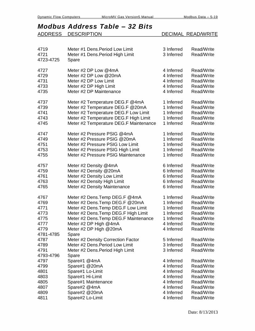
Dynamic Flow Computers MicroMV Gas Version5 Manual Modbus Data – 5-19
Modbus Address Table – 32 Bits ADDRESS DESCRIPTION DECIMAL READ/WRITE
Date: 8/13/2013
4719 Meter #1 Dens.Period Low Limit 3 Inferred Read/Write 4721 Meter #1 Dens.Period High Limit 3 Inferred Read/Write 4723-4725 Spare 4727 Meter #2 DP Low @4mA 4 Inferred Read/Write 4729 Meter #2 DP Low @20mA 4 Inferred Read/Write 4731 Meter #2 DP Low Limit 4 Inferred Read/Write 4733 Meter #2 DP High Limit 4 Inferred Read/Write 4735 Meter #2 DP Maintenance 4 Inferred Read/Write 4737 Meter #2 Temperature DEG.F @4mA 1 Inferred Read/Write 4739 Meter #2 Temperature DEG.F @20mA 1 Inferred Read/Write 4741 Meter #2 Temperature DEG.F Low Limit 1 Inferred Read/Write 4743 Meter #2 Temperature DEG.F High Limit 1 Inferred Read/Write 4745 Meter #2 Temperature DEG.F Maintenance 1 Inferred Read/Write 4747 Meter #2 Pressure PSIG @4mA 1 Inferred Read/Write 4749 Meter #2 Pressure PSIG @20mA 1 Inferred Read/Write 4751 Meter #2 Pressure PSIG Low Limit 1 Inferred Read/Write 4753 Meter #2 Pressure PSIG High Limit 1 Inferred Read/Write 4755 Meter #2 Pressure PSIG Maintenance 1 Inferred Read/Write 4757 Meter #2 Density @4mA 6 Inferred Read/Write 4759 Meter #2 Density @20mA 6 Inferred Read/Write 4761 Meter #2 Density Low Limit 6 Inferred Read/Write 4763 Meter #2 Density High Limit 6 Inferred Read/Write 4765 Meter #2 Density Maintenance 6 Inferred Read/Write 4767 Meter #2 Dens.Temp DEG.F @4mA 1 Inferred Read/Write 4769 Meter #2 Dens.Temp DEG.F @20mA 1 Inferred Read/Write 4771 Meter #2 Dens.Temp DEG.F Low Limit 1 Inferred Read/Write 4773 Meter #2 Dens.Temp DEG.F High Limit 1 Inferred Read/Write 4775 Meter #2 Dens.Temp DEG.F Maintenance 1 Inferred Read/Write 4777 Meter #2 DP High @4mA 4 Inferred Read/Write 4779 Meter #2 DP High @20mA 4 Inferred Read/Write 4781-4785 Spare 4787 Meter #2 Density Correction Factor 5 Inferred Read/Write 4789 Meter #2 Dens.Period Low Limit 3 Inferred Read/Write 4791 Meter #2 Dens.Period High Limit 3 Inferred Read/Write 4793-4796 Spare 4797 Spare#1 @4mA 4 Inferred Read/Write 4799 Spare#1 @20mA 4 Inferred Read/Write 4801 Spare#1 Lo-Limit 4 Inferred Read/Write 4803 Spare#1 Hi-Limit 4 Inferred Read/Write 4805 Spare#1 Maintenance 4 Inferred Read/Write 4807 Spare#2 @4mA 4 Inferred Read/Write 4809 Spare#2 @20mA 4 Inferred Read/Write 4811 Spare#2 Lo-Limit 4 Inferred Read/Write

Dynamic Flow Computers MicroMV Gas Version5 Manual Modbus Data – 5-20
Modbus Address Table – 32 Bits ADDRESS DESCRIPTION DECIMAL READ/WRITE
Date: 8/13/2013
4813 Spare#2 Hi-Limit 4 Inferred Read/Write 4815 Spare#2 Maintenance 4 Inferred Read/Write 4817 Spare 4819 Base Temperature DEG.F 3 Inferred Read/Write 4821 Base Pressure PSIA 3 Inferred Read/Write 4823 Run Switch Low Set Point 2 Inferred Read/Write 4825 Run Switch High Set Point 2 Inferred Read/Write 4827 Atmospheric Pressure PSIA 3 Inferred Read/Write 4829 Pulse Output Volume #1 Pulses/Unit 3 Inferred Read/Write 4831 Pulse Output Volume #2 Pulses/Unit 3 Inferred Read/Write 4833 Analog Output #1 at 4 mA 4835 Analog Output #1 at 20 mA 4837 Analog Output #2 at 4 mA 4839 Analog Output #2 at 20 mA 4841 Analog Output #3 at 4 mA 4843 Analog Output #3 at 20 mA 4845 Analog Output #4 at 4 mA 4847 Analog Output #4 at 20 mA Scratch Pad for Program Variables – (Long Integer) 5031,5033-5069
5031 Sratch Pad – Program Variable Integer 5033 5035 5037 5039 5041 5043 5045 5047 5049 5051

Dynamic Flow Computers MicroMV Gas Version5 Manual Modbus Data – 5-21
Modbus Address Table – 32 Bits ADDRESS DESCRIPTION DECIMAL READ/WRITE
Date: 8/13/2013
Last Hourly Data Area
3787 = Requested Date (mmddyy) (32 bits) 3028 = Requested Hour (16 bits) 3029 = Last Hourly Report Request (16 bits) Set requested date, set requested hour, and then set last hourly report request to 1 in that order.
3787 = Requested Date (mmddyy) (32 bits) 3028 = Requested Hour (16 bits) 3029 = Last Hourly Report Request (16 bits) Set requested date, set requested hour, and then set last hourly report request to 1 in that order.
8001 Date (mm/dd/yy) 0 Inferred Read 8003 Time (hh/mm/ss) 0 Inferred Read 8005 Meter#1 Hourly Duration of Flow 1 Inferred Read 8007 Meter#1 GrossTotal 0 Inferred Read 8009 Meter#1 Net Total 0 Inferred Read 8011 Meter#1 Mass Total 0 Inferred Read 8013 Meter#1 Energy Total 0 Inferred Read 8015 Meter#1 Average Temperature 1 Inferred Read 8017 Meter#1 Average Pressure 1 Inferred Read 8019 Meter#1 Average DP 4 Inferred Read 8021 Meter#1 Average DP EXT 4 Inferred Read 8023 Meter#1 Average SG 6 Inferred Read 8025 Meter#2 Hourly Duration of Flow 1 Inferred Read 8027 Meter#2 Gross Total 0 Inferred Read 8029 Meter#2 Net Total 0 Inferred Read 8031 Meter#2 Mass Total 0 Inferred Read 8033 Meter#2 Energy Total 0 Inferred Read 8035 Meter#2 Average Temperature 1 Inferred Read 8037 Meter#2 Average Pressure 1 Inferred Read 8039 Meter#2 Average DP 4 Inferred Read 8041 Meter#2 Average DP EXT 4 Inferred Read 8043 Meter#2 Average SG 6 Inferred Read LAST HO URLY DATA AREA EN DS

Dynamic Flow Computers MicroMV Gas Version5 Manual Modbus Data – 5-22
Modbus Address Table – 32 Bits ADDRESS DESCRIPTION DECIMAL READ/WRITE
Date: 8/13/2013
*Non-resettable accumulated volume will roll over at 9999999.
CURRENT DATA AREA 9001 Meter #1 Calculation Type 0 Inferred Read 9003 Meter #1 Flow Flag/Flow Dir 0 Inferred Read 9005 Meter #1 Alarm Status Flag 0 Inferred Read 9007 Meter #1 Daily Gross Total 0 inferred Read 9009 Meter #1 Daily Net Total 0 inferred Read 9011 Meter #1 Daily Mass Total 0 inferred Read 9013 Meter #1 Daily Energy Total 0 inferred Read 9015 Meter #1 N2 4 Inferred Read 9017 Meter #1 Co2 4 Inferred Read 9019 Meter #1 Methane 4 Inferred Read 9021 Meter #1 Ethane 4 Inferred Read 9023 Meter #1 Propane 4 Inferred Read 9025 Meter #1 Water 4 Inferred Read 9027 Meter #1 H2S 4 Inferred Read 9029 Meter #1 H2 4 Inferred Read 9031 Meter #1 CO 4 Inferred Read 9033 Meter #1 Oxygen 4 Inferred Read 9035 Meter #1 I-Butane 4 Inferred Read 9037 Meter #1 n-Butane 4 Inferred. Read 9039 Meter#1 Heating Value 3 Inferred Read 9041 Meter #1 Gross Flowrate 2 Inferred Read 9043 Meter #1 Net Flowrate 2 Inferred Read 9045 Meter #1 Mass Flowrate 2 Inferred Read 9047 Meter #1 Energy Flowrate 2 Inferred Read 9049 Meter #1 DP 4 Inferred Read 9051 Meter #1 Temperature 1 Inferred Read 9053 Meter #1 Pressure 1 Inferred Read 9055 Meter #1 Density 6 Inferred Read 9057 Meter #1 Dens.Temp 1 Inferred Read 9059 Meter #1 Dens.b 6 Inferred Read 9061 Meter #1 SG 6 Inferred Read 9063 Meter #1 Y Factor 6 Inferred Read 9065 Meter #1 K /CD/LMF 6 Inferred Read 9067 Meter #1 FA 6 Inferred Read 9069 Meter #1 FPV 6 Inferred Read 9071-9081 Spare 9083 Meter #1 I-Pentane 4 Inferred Read 9085 Meter #1 n-Pentane 4 Inferred Read 9087 Meter #1 n-Hexane 4 Inferred Read 9089 Meter #1 n-Heptane 4 Inferred Read 9091 Meter #1 n-Octane 4 Inferred Read 9093 Meter #1 n-Nonane 4 Inferred Read 9095 Meter #1 n-Decane 4 Inferred Read 9097 Meter #1 Helium 4 Inferred Read

Dynamic Flow Computers MicroMV Gas Version5 Manual Modbus Data – 5-23
Modbus Address Table – 32 Bits ADDRESS DESCRIPTION DECIMAL READ/WRITE
Date: 8/13/2013
9099 Meter #1 Argon 4 Inferred Read 9101 Meter #1 DP EXT 4 Inferred Read 9103-9131 Spare 9133 Meter #1 Cum. Gross Total* 0 Inferred Read 9135 Meter #1 Cum. Net Total* 0 Inferred Read 9137 Meter #1 Cum. Mass Total* 0 Inferred Read 9139 Meter #1 Cum. Energy Total* 0 Inferred Read 9141 Meter #1 Density Calc. Type 0 Inferred Read 9143-9145 Meter #1 Meter ID 8 Chars. Read 9147 Meter #1 Pipe ID 5 Inferred Read 9149 Meter #1 Orifice ID 5 Inferred Read 9151 Meter #1 Density Correction Factor 5 Inferred Read 9153 Meter #1 Density of Dry Air 5 Inferred Read 9155 Meter #1 Heating Value BTU/FT3 3 Inferred Read 9157 Meter #1 K Factor 3 Inferred Read 9159 Date (mmddyy) 0 Inferred Read 9161 Time (hhmmss) 0 Inferred Read 9163-9199 Spare 9201 Meter #2 Calculation Type 0 Inferred Read 9203 Meter #2 Flow Flag/Flow Dir 0 Inferred Read 9205 Meter #2 Alarm Status Flag 0 Inferred Read 9207 Meter #2 Daily Gross 0 inferred Read 9209 Meter #2 Daily Net 0 inferred Read 9211 Meter #2 Daily Mass 0 inferred Read 9213 Meter #2 Daily Energy 0 inferred Read 9215 Meter #2 N2 4 Inferred Read 9217 Meter #2 Co2 4 Inferred Read 9219 Meter #2 Methane 4 Inferred Read 9221 Meter #2 Ethane 4 Inferred Read 9223 Meter #2 Propane 4 Inferred Read 9225 Meter #1 Water 4 Inferred Read 9227 Meter #2 H2S 4 Inferred Read 9229 Meter #2 H2 4 Inferred Read 9231 Meter #2 CO 4 Inferred Read 9233 Meter #2 Oxygen 4 Inferred Read 9235 Meter #2 I-Butane 4 Inferred Read 9237 Meter #2 n-Butane 4 Inferred. Read 9239 Meter#2 Heating Value 3 Inferred Read 9241 Meter #2 Gross Flowrate 2 Inferred Read 9243 Meter #2 Net Flowrate 2 Inferred Read 9245 Meter #2 Mass Flowrate 2 Inferred Read 9247 Meter #2 Energy Flowrate 2 Inferred Read 9249 Meter #2 DP 4 Inferred Read

Dynamic Flow Computers MicroMV Gas Version5 Manual Modbus Data – 5-24
Modbus Address Table – 32 Bits ADDRESS DESCRIPTION DECIMAL READ/WRITE
Date: 8/13/2013
9251 Meter #2 Temperature 1 Inferred Read 9253 Meter #2 Pressure 1 Inferred Read 9255 Meter #2 Density 6 Inferred Read 9257 Meter #2 Dens.Temp 1 Inferred Read 9259 Meter #2 Dens.b 6 Inferred Read 9261 Meter #2 SG 6 Inferred Read 9263 Meter #2 Y Factor 6 Inferred Read 9265 Meter #2 K /CD/LMF 6 Inferred Read 9267 Meter #2 FA 6 Inferred Read 9269 Meter #2 FPV 6 Inferred Read 9271-9281 Spare 9283 Meter #2 I-Pentane 4 Inferred Read 9285 Meter #2 n-Pentane 4 Inferred Read 9287 Meter #2 n-Hexane 4 Inferred Read 9289 Meter #2 n-Heptane 4 Inferred Read 9291 Meter #2 n-Octane 4 Inferred Read 9293 Meter #2 n-Nonane 4 Inferred Read 9295 Meter #2 n-Decane 4 Inferred Read 9297 Meter #2 Helium 4 Inferred Read 9299 Meter #2 Argon 4 Inferred Read 9301 Meter #2 DP EXT 4 Inferred Read 9303-9331 Spare 9333 Meter #2 Cum. Gross Total* 0 Inferred Read 9335 Meter #2 Cum. Net Total* 0 Inferred Read 9337 Meter #2 Cum. Mass Total* 0 Inferred Read 9339 Meter #2 Cum. Energy Total* 0 Inferred Read 9341 Meter #2 Density Calc. Type 0 Inferred Read 9343-9345 Meter #2 Meter ID 8 Chars. Read 9347 Meter #2 Pipe ID 5 Inferred Read 9349 Meter #2 Orifice ID 5 Inferred Read 9351 Meter #2 Density Correction Factor 5 Inferred Read 9353 Meter #2 Density of Dry Air 5 Inferred Read 9355 Meter #2 Heating Value BTU/FT3 3 Inferred Read 9357 Meter #2 K Factor 3 Inferred Read 9359-9399 Spare 9401 Spare #1 Data 4 Inferred Read 9403 Spare #2 Data 4 Inferred Read
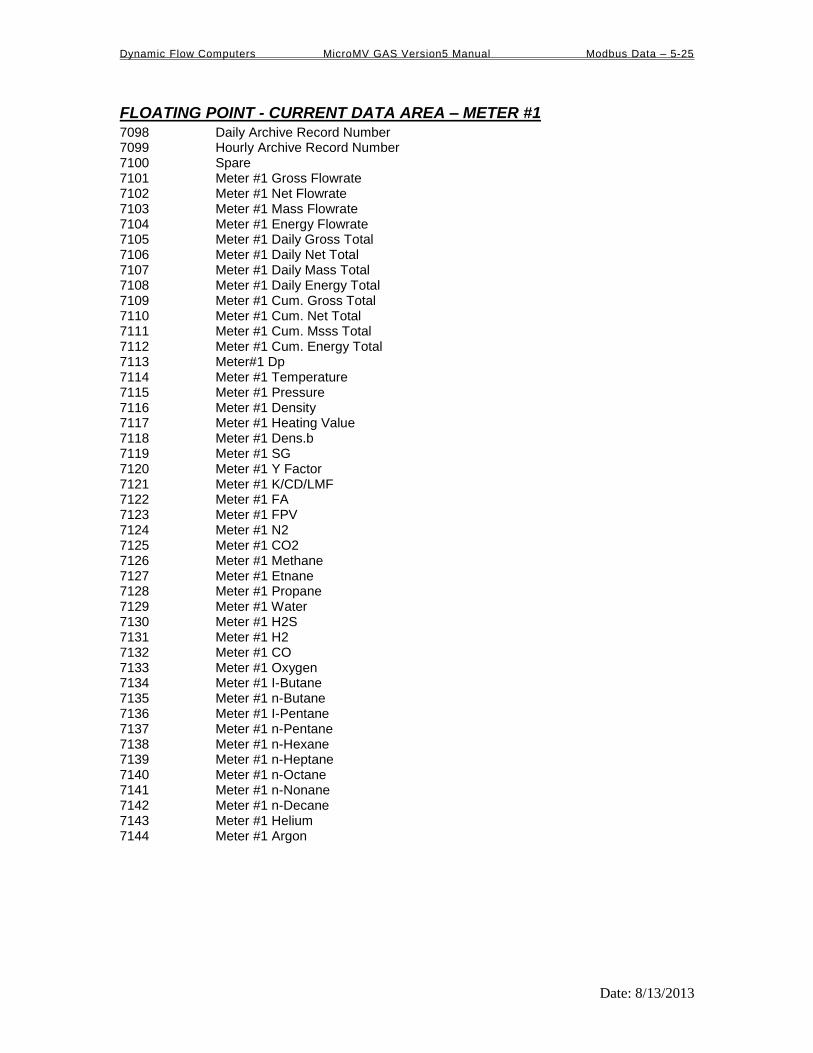
Dynamic Flow Computers MicroMV GAS Version5 Manual Modbus Data – 5-25
Date: 8/13/2013
FLOATING POINT - CURRENT DATA AREA – METER #1 7098 Daily Archive Record Number 7099 Hourly Archive Record Number 7100 Spare 7101 Meter #1 Gross Flowrate 7102 Meter #1 Net Flowrate 7103 Meter #1 Mass Flowrate 7104 Meter #1 Energy Flowrate 7105 Meter #1 Daily Gross Total 7106 Meter #1 Daily Net Total 7107 Meter #1 Daily Mass Total 7108 Meter #1 Daily Energy Total 7109 Meter #1 Cum. Gross Total 7110 Meter #1 Cum. Net Total 7111 Meter #1 Cum. Msss Total 7112 Meter #1 Cum. Energy Total 7113 Meter#1 Dp 7114 Meter #1 Temperature 7115 Meter #1 Pressure 7116 Meter #1 Density 7117 Meter #1 Heating Value 7118 Meter #1 Dens.b 7119 Meter #1 SG 7120 Meter #1 Y Factor 7121 Meter #1 K/CD/LMF 7122 Meter #1 FA 7123 Meter #1 FPV 7124 Meter #1 N2 7125 Meter #1 CO2 7126 Meter #1 Methane 7127 Meter #1 Etnane 7128 Meter #1 Propane 7129 Meter #1 Water 7130 Meter #1 H2S 7131 Meter #1 H2 7132 Meter #1 CO 7133 Meter #1 Oxygen 7134 Meter #1 I-Butane 7135 Meter #1 n-Butane 7136 Meter #1 I-Pentane 7137 Meter #1 n-Pentane 7138 Meter #1 n-Hexane 7139 Meter #1 n-Heptane 7140 Meter #1 n-Octane 7141 Meter #1 n-Nonane 7142 Meter #1 n-Decane 7143 Meter #1 Helium 7144 Meter #1 Argon

Dynamic Flow Computers MicroMV GAS Version5 Manual Modbus Data – 5-26
Date: 8/13/2013
FLOATING POINT - CURRENT DATA AREA
7145-7153 Spare 7154 Meter #1 Alarms (4th byte | 3rd byte | 2nd byte | 1st byte)
1 st Btye – B0 : Flowrate High Alarm B1 : Flowrate Low Alarm B2 : Temperature High Alarm B3 : Temperature Low Alarm B4 : Pressure High Alarm B5 : Pressure Low Alarm B6 : Density/Gravity High Alarm B7 : Density/Gravity Low Alarm 2 nd Byte B0 : Dens.Temperature High Alarm B1 : Dens.Temperature Low Alarm B2 : DP High Alarm B3 : DP Low Alarm B4 : Dens.Period High Alarm B5 : Dens.Period Low Alarm 3 rd Byte B0 : Down B1 : NX19 Out of Range B2 : AGA8 Out of Range

Dynamic Flow Computers MicroMV GAS Version5 Manual Modbus Data – 5-27
Date: 8/13/2013
FLOATING POINT- CURRENT DATA AREA – METER #2
7301 Meter #2 Gross Flowrate 7302 Meter #2 Net Flowrate 7303 Meter #2 Mass Flowrate 7304 Meter #2 Energy Flowrate 7305 Meter #2 Daily Gross Total 7306 Meter #2 Daily Net Total 7307 Meter #2 Daily Mass Total 7308 Meter #2 Daily Energy Total 7309 Meter #2 Cum. Gross Total 7310 Meter #2 Cum. Net Total 7311 Meter #2 Cum. Msss Total 7312 Meter #2 Cum. Energy Total 7313 Meter#2 Dp 7314 Meter #2 Temperature 7315 Meter #2 Pressure 7316 Meter #2 Density 7317 Meter #2 Heating Value 7318 Meter #2 Dens.b 7319 Meter #2 SG 7320 Meter #2 Y Factor 7321 Meter #2 K/CD/LMF 7322 Meter #2 FA 7323 Meter #2 FPV 7324 Meter #2 N2 7325 Meter #2 CO2 7326 Meter #2 Methane 7327 Meter #2 Etnane 7328 Meter #2 Propane 7329 Meter #2 Water 7330 Meter #2 H2S 7331 Meter #2 H2 7332 Meter #2 CO 7333 Meter #2 Oxygen 7334 Meter #2 I-Butane 7335 Meter #2 n-Butane 7336 Meter #2 I-Pentane 7337 Meter #2 n-Pentane 7338 Meter #2 n-Hexane 7339 Meter #2 n-Heptane 7340 Meter #2 n-Octane 7341 Meter #2 n-Nonane 7342 Meter #2 n-Decane 7343 Meter #2 Helium 7344 Meter #2 Argon

Dynamic Flow Computers MicroMV GAS Version5 Manual Modbus Data – 5-28
Date: 8/13/2013
FLOATING POINT- CURRENT DATA AREA – METER #2
7345-7352 Spare 7353 Meter #2 Alarms (4 th byte | 3rd byte | 2nd byte | 1st byte)
1 st Btye – B0 : Flowrate High Alarm B1 : Flowrate Low Alarm B2 : Temperature High Alarm B3 : Temperature Low Alarm B4 : Pressure High Alarm B5 : Pressure Low Alarm B6 : Density/Gravity High Alarm B7 : Density/Gravity Low Alarm 2 nd Byte B0 : Dens.Temperature High Alarm B1 : Dens.Temperature Low Alarm B2 : DP High Alarm B3 : DP Low Alarm B4 : Dens.Period High Alarm B5 : Dens.Period Low Alarm 3 rd Byte B0 : Down B1 : NX19 Out of Range B2 : AGA8 Out of Range

Dynamic Flow Computers MicroMV GAS Version5 Manual Modbus Data – 5-29
Date: 8/13/2013
FLOATING POINT – Previous Daily Data Area – Meter #1
7201 Date 7202 Time 7203 Flow Time (Min) 7204 Meter #1 Average DP 7205 Meter #1 Average Pressure 7206 Meter #1 Average Temperature 7207 Meter #1 Average DP/EXT 7208 Meter #1 Gross Total 7209 Meter #1 Net Total 7210 Meter #1 Mass Total 7211 Meter #1 Energy Total 7212 Meter #1 Average Heating Value 7213 Meter #1 Average SG 7214 Meter #1 Average N2 7215 Meter #1 Average CO2 7216 Meter #1 Average Methane 7217 Meter #1 Average Ethane 7218 Meter #1 Average Propane 7219 Meter #1 Average Water 7220 Meter #1 Average H2S 7221 Meter #1 Average H2 7222 Meter #1 Average CO 7223 Meter #1 Average Oxygen 7224 Meter #1 Average I-Butane 7225 Meter #1 Average n-Butane 7226 Meter #1 Average I-Pentane 7227 Meter #1 Average n-Pentane 7228 Meter #1 Average n-Hexane 7229 Meter #1 Average n-Heptane 7230 Meter #1 Average n-Octane 7231 Meter #1 Average n-Nonane 7232 Meter #1 Average n-Decane 7233 Meter #1 Average Helium 7234 Meter #1 Average Argon

Dynamic Flow Computers MicroMV GAS Version5 Manual Modbus Data – 5-30
Date: 8/13/2013
FLOATING POINT – Previous Hourly Data Area – Meter #1
7241 Date 7242 Time 7243 Flow Time 7244 Meter #1 Average DP 7245 Meter #1 Average Pressure 7246 Meter #1 Average Temperature 7247 Meter #1 Average DP/EXT 7248 Meter #1 Hourly Gross 7249 Meter #1 Hourly Net 7250 Meter #1 Hourly Mass 7251 Meter #1 Hourly Energy 7252 Program Variable #1 7253 Program Variable #2 7254 Program Variable #3 7255 Program Variable #4 7256 Program Variable #5 7257 Program Variable #6 7258 Program Variable #7 7259 Program Variable #8 7260 Program Variable #9 7261 Program Variable #10
FLOATING POINT – Previous Daily Data Area – Prog.Var
7262 Flow Time (Min) 7263 Program Variable #1 7264 Program Variable #2 7265 Program Variable #3 7266 Program Variable #4 7267 Program Variable #5 7268 Program Variable #6 7269 Program Variable #7 7270 Program Variable #8 7271 Program Variable #9 7272 Program Variable #10

Dynamic Flow Computers MicroMV GAS Version5 Manual Modbus Data – 5-31
Date: 8/13/2013
FLOATING POINT – Previous Daily Data Area – Meter #2
7401 Date 7402 Time 7403 Flow Time (Min) 7404 Meter #2 Average DP 7405 Meter #2 Average Pressure 7406 Meter #2 Average Temperature 7407 Meter #2 Average DP/EXT 7408 Meter #2 Gross Total 7409 Meter #2 Net Total 7410 Meter #2 Mass Total 7411 Meter #2 Energy Total 7412 Meter #2 Average Heating Value 7413 Meter #2 Average SG 7414 Meter #2 Average N2 7415 Meter #2 Average CO2 7416 Meter #2 Average Methane 7417 Meter #2 Average Ethane 7418 Meter #2 Average Propane 7419 Meter #2 Average Water 7420 Meter #2 Average H2S 7421 Meter #2 Average H2 7422 Meter #2 Average CO 7423 Meter #2 Average Oxygen 7424 Meter #2 Average I-Butane 7425 Meter #2 Average n-Butane 7426 Meter #2 Average I-Pentane 7427 Meter#2 Average n-Pentane 7428 Meter #2 Average n-Hexane 7429 Meter #2 Average n-Heptane 7430 Meter #2 Average n-Octane 7431 Meter #2 Average n-Nonane 7432 Meter #2 Average n-Decane 7433 Meter #2 Average Helium 7434 Meter #2 Average Argon
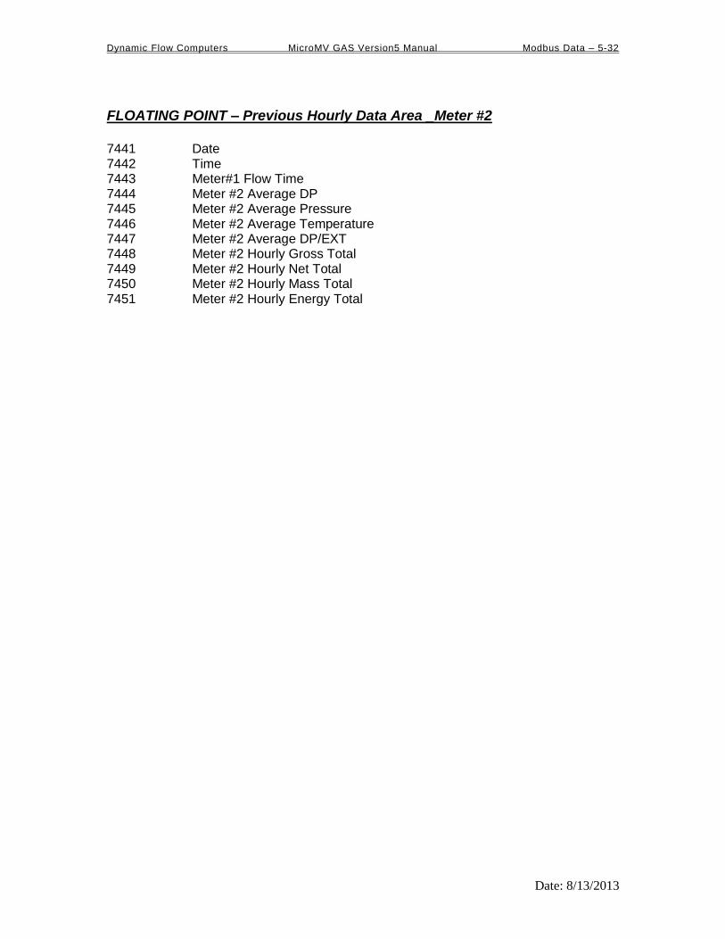
Dynamic Flow Computers MicroMV GAS Version5 Manual Modbus Data – 5-32
Date: 8/13/2013
FLOATING POINT – Previous Hourly Data Area _Meter #2
7441 Date 7442 Time 7443 Meter#1 Flow Time 7444 Meter #2 Average DP 7445 Meter #2 Average Pressure 7446 Meter #2 Average Temperature 7447 Meter #2 Average DP/EXT 7448 Meter #2 Hourly Gross Total 7449 Meter #2 Hourly Net Total 7450 Meter #2 Hourly Mass Total 7451 Meter #2 Hourly Energy Total

Dynamic Flow Computers MicroMV GAS Version5 Manual Modbus Data – 5-33
Date: 8/13/2013
3123 (16 bits) ACK FLAG 0 Inferred Read/Write
FLOATING POINT – (701) Previous Daily Data Area – Meter #1 701 Date
Time Average Heating Value Average SG Average Carbon Dioxide Average Nitrogen Average Methane Average Ethane Average Propane Average Iso-Butane Average n-Butane Average I-Pentane Average n-Pentane Average Hexane Average Heptane Average Nonane Average Octane Average H2S Average Hydrogen Average Helium Average Oxygen Average Carbon Monoxide
FLOATING POINT – (702) Previous Daily Data Area – Meter #2
702 Date Time
Average Heating Value Average SG Average Carbon Dioxide Average Nitrogen Average Methane Average Ethane Average Propane Average Iso-Butane Average n-Butane Average I-Pentane Average n-Pentane Average Hexane Average Heptane Average Nonane Average Octane Average H2S Average Hydrogen Average Helium Average Oxygen Average Carbon Monoxide

Dynamic Flow Computers MicroMV GAS Version5 Manual Modbus Data – 5-34
Date: 8/13/2013
FLOATING POINT – (703) Previous Daily Data Area – Meter #1
703 Date Time Flow Time (Min.) Average Pressure Average Temperature Gross Total Net Total Mass Total Energy Average DP Average DP/EXT
FLOATING POINT – (704) Previous Hourly Data Area – Meter #1
704 Date Time Flow Time (Min.) Average Pressure Average Temperature Gross Total Net Total Mass Total Energy Total Average DP Average DP/EXT

Dynamic Flow Computers MicroMV GAS Version5 Manual Modbus Data – 5-35
Date: 8/13/2013
FLOATING POINT – (705) Previous Daily Data Area – Meter #2
705 Date Time Flow Time (Min.) Average Pressure Average Temperature Gross Total Net Total Mass Total Energy Total Average DP Average DP/EXT
FLOATING POINT – (706) Previous Hourly Data Area – Meter #2
706 Date Time Flow Time (Min.) Average Pressure Average Temperature Gross Total Net Total Mass Total Energy Total Average DP Average DP/EXT

Dynamic Flow Computers MicroMV GAS Version5 Manual Modbus Data – 5-36
Date: 8/13/2013
Programmable Floating Point Variable Scratch Pad for Floating Point Variables – 7801-7830
7791-7800 – Last Hour Program Variables 7801-7810 –first 5 Variables, will be reset at the end of hour. 7831-7899 – Programmable Variable Statements
Hourly Programmable Variables 7052-7061
3787 = Requested Date (mmddyy) (32 bits) 3028 = Requested Hour (16 bits) 3029 = Last Hourly Report Request (16 bits) Set requested date, set requested hour, and then set last hourly report request to 1 in that order.
7052 Hourly Programmable Variables #1
7053 Hourly Programmable Variables #2
7054 Hourly Programmable Variables #3
7055 Hourly Programmable Variables #4
7056 Hourly Programmable Variables #5
7057 Hourly Programmable Variables #6
7058 Hourly Programmable Variables #7
7059 Hourly Programmable Variables #8
7060 Hourly Programmable Variables #9
7061 Hourly Programmable Variables #10

Dynamic Flow Computers MicroMV GAS Version5 Manual Drawings – 6-1
Date: 8/13/2013
CHAPTER 6: Installation Drawings
Explosion-Proof Installation Drawings

Dynamic Flow Computers MicroMV GAS Version5 Manual Drawings – 6-2
Date: 8/13/2013

Dynamic Flow Computers MicroMV GAS Version5 Manual Drawings – 6-3
Date: 8/13/2013

Dynamic Flow Computers MicroMV GAS Version5 Manual Drawings – 6-4
Date: 8/13/2013
Manifold Installation Drawings

Dynamic Flow Computers MicroMV GAS Version5 Manual Drawings – 6-5
Date: 8/13/2013

Dynamic Flow Computers MicroMV GAS Version5 Manual Drawings – 6-6
Date: 8/13/2013

Dynamic Flow Computers MicroMV GAS Version5 Manual Drawings – 6-7
Date: 8/13/2013