Setting Up Your Drawing Environment - Jim...
28
In This Chapter 67 3 Setting Up Your Drawing Environment After you start a drawing, you can change its settings, including drawing units and limits, snap and grid settings, and layer, linetype, and lettering standards. You can also modify the AutoCAD ® environment to fit your personal preferences or the needs of a particular project. This chapter describes the drawing settings and AutoCAD options that you can modify. ■ Formatting drawing units ■ Changing grid and snap settings ■ Setting AutoCAD options ■ Defining drawing properties ■ Changing toolbars and toolbar buttons
Transcript of Setting Up Your Drawing Environment - Jim...

In This Chapter
67
3
Setting Up Your Drawing Environment
After you start a drawing, you can change its settings,
including drawing units and limits, snap and grid
settings, and layer, linetype, and lettering standards.
You can also modify the AutoCAD® environment to fit
your personal preferences or the needs of a particular
project. This chapter describes the drawing settings
and AutoCAD options that you can modify.
■ Formatting drawing units
■ Changing grid and snap settings
■ Setting AutoCAD options
■ Defining drawing properties
■ Changing toolbars and toolbar buttons
68 | Chapter 3 Setting Up Your Drawing Environment
Setting Drawing Units
Every object you draw is measured in units. You determine the value of the units within AutoCAD before you draw. For example, in one drawing, a unit might equal one millimeter of the real-world object. In another drawing, a unit might equal an inch. You can set the unit type and number of decimal places for object lengths and angles. You can also specify the units for blocks and other content you insert from AutoCAD DesignCenter (see chapter 14, “Managing Content with AutoCAD DesignCenter”). Drawing unit settings control how AutoCAD interprets your coordinate and angle entries and how it displays coordinates and units in the drawing and in dialog boxes (see “Set-ting User Preferences” on page 80).
Setting drawing units does not automatically set units for dimensions (see “Formatting Primary Dimension Units” on page 422). You generally set drawing units and dimension units to the same type and precision, but you can set different values for dimension units.
To format drawing units
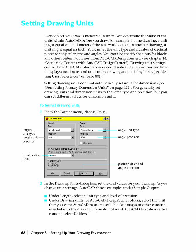
1 From the Format menu, choose Units.
2 In the Drawing Units dialog box, set the unit values for your drawing. As you change unit settings, AutoCAD shows examples under Sample Output.
■ Under Length, select a unit type and level of precision.■ Under Drawing units for AutoCAD DesignCenter blocks, select the unit
that you want AutoCAD to use to scale blocks, images or other content inserted into the drawing. If you do not want AutoCAD to scale inserted content, select Unitless.
length unit typelength unit precision
angle unit type
angle precision
position of 0° and angle direction
insert scaling units
Setting Drawing Units | 69
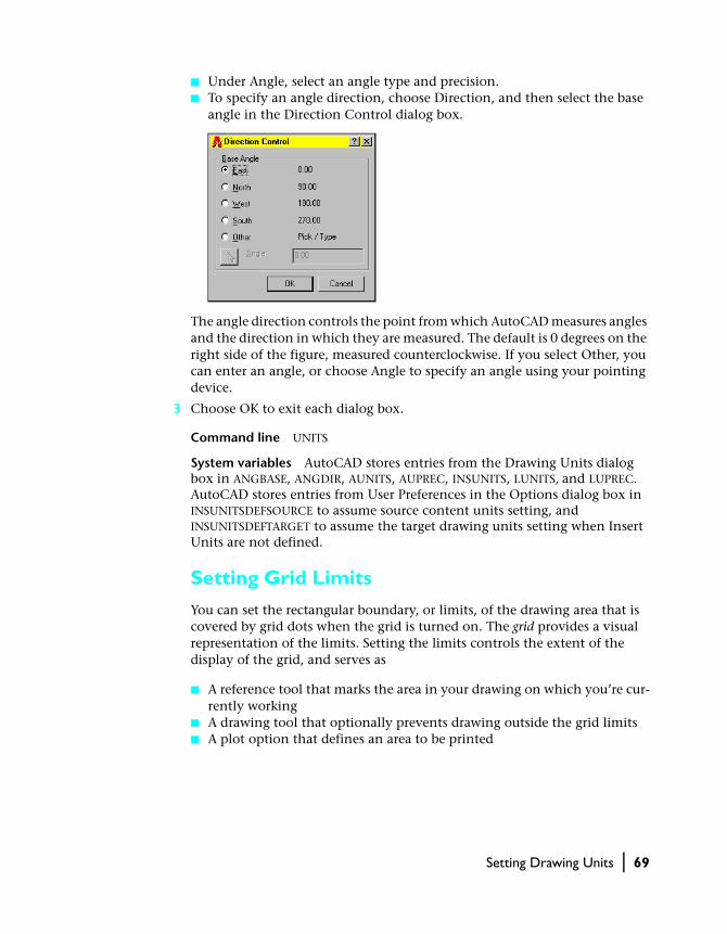
■ Under Angle, select an angle type and precision.■ To specify an angle direction, choose Direction, and then select the base
angle in the Direction Control dialog box.
The angle direction controls the point from which AutoCAD measures angles and the direction in which they are measured. The default is 0 degrees on the right side of the figure, measured counterclockwise. If you select Other, you can enter an angle, or choose Angle to specify an angle using your pointing device.
3 Choose OK to exit each dialog box.
Command line UNITS
System variables AutoCAD stores entries from the Drawing Units dialog box in ANGBASE, ANGDIR, AUNITS, AUPREC, INSUNITS, LUNITS, and LUPREC. AutoCAD stores entries from User Preferences in the Options dialog box in INSUNITSDEFSOURCE to assume source content units setting, and INSUNITSDEFTARGET to assume the target drawing units setting when Insert Units are not defined.
Setting Grid Limits
You can set the rectangular boundary, or limits, of the drawing area that is covered by grid dots when the grid is turned on. The grid provides a visual representation of the limits. Setting the limits controls the extent of the display of the grid, and serves as
■ A reference tool that marks the area in your drawing on which you’re cur-rently working
■ A drawing tool that optionally prevents drawing outside the grid limits■ A plot option that defines an area to be printed
70 | Chapter 3 Setting Up Your Drawing Environment
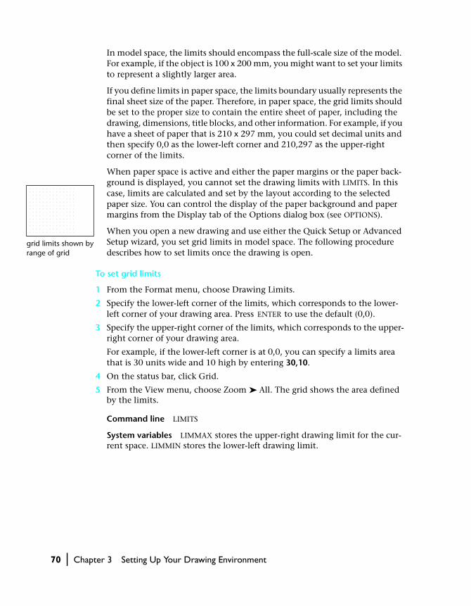
In model space, the limits should encompass the full-scale size of the model. For example, if the object is 100 x 200 mm, you might want to set your limits to represent a slightly larger area.
If you define limits in paper space, the limits boundary usually represents the final sheet size of the paper. Therefore, in paper space, the grid limits should be set to the proper size to contain the entire sheet of paper, including the drawing, dimensions, title blocks, and other information. For example, if you have a sheet of paper that is 210 x 297 mm, you could set decimal units and then specify 0,0 as the lower-left corner and 210,297 as the upper-right corner of the limits.
When paper space is active and either the paper margins or the paper back-ground is displayed, you cannot set the drawing limits with LIMITS. In this case, limits are calculated and set by the layout according to the selected paper size. You can control the display of the paper background and paper margins from the Display tab of the Options dialog box (see OPTIONS).
When you open a new drawing and use either the Quick Setup or Advanced Setup wizard, you set grid limits in model space. The following procedure describes how to set limits once the drawing is open.
To set grid limits
1 From the Format menu, choose Drawing Limits.
2 Specify the lower-left corner of the limits, which corresponds to the lower-left corner of your drawing area. Press ENTER to use the default (0,0).
3 Specify the upper-right corner of the limits, which corresponds to the upper-right corner of your drawing area.
For example, if the lower-left corner is at 0,0, you can specify a limits area that is 30 units wide and 10 high by entering 30,10.
4 On the status bar, click Grid.
5 From the View menu, choose Zoom ➤ All. The grid shows the area defined by the limits.
Command line LIMITS
System variables LIMMAX stores the upper-right drawing limit for the cur-rent space. LIMMIN stores the lower-left drawing limit.
grid limits shown by range of grid

Setting Drawing Units | 71
Setting the Grid
The grid is a pattern of dots that extends over the area specified by the limits. Using the grid is similar to placing a sheet of grid paper under a drawing. The grid helps you align objects and visualize the distances between them. You can turn the grid on and off in the middle of another command. The grid is not displayed in the plotted drawing.
If you zoom in or out of your drawing, you might need to adjust grid spacing to be more appropriate for the new magnification.
To turn on the grid and set grid spacing
1 From the Tools menu, choose Drafting Settings.
2 On the Snap and Grid tab of the Drafting Settings dialog box, select Grid On.
3 Enter the value for Grid X Spacing in units.
4 To use the same value for vertical grid spacing, press ENTER. Otherwise, enter a new value for Grid Y Spacing.
5 Choose OK.
To turn the grid on or off, click Grid on the status bar, use the GRID com-mand, press CTRL +G, or press F7.
Command line DSETTINGS
Shortcut menu Right-click Grid on the status bar and choose Settings.

72 | Chapter 3 Setting Up Your Drawing Environment
Setting Snap Spacing
Snap mode restricts the movement of the crosshairs to intervals that you have defined. When Snap is on, the cursor seems to adhere, or “snap,” to an invisible grid. Snap is useful for specifying precise points with the keyboard or pointing device. You control snap precision by setting the X and Y spac-ing. Snap has a toggle control and can be turned on or off during another command.
Snap spacing does not have to match grid spacing. For example, you might set a wide grid spacing to be used as a reference but maintain a closer snap spacing for accuracy in specifying points. You also can set the grid spacing to be smaller than the snap spacing.
To turn on Snap mode and set snap spacing
1 From the Tools menu, choose Drafting Settings.
2 On the Snap and Grid tab of the Drafting Settings dialog box, select Snap On.
3 Enter the value for Snap X Spacing in units.
4 To specify the same vertical snap spacing, press ENTER. Otherwise, enter the value for Snap Y Spacing.
5 Under Snap Style & Type, select Rectangular Snap and Grid Snap. (For infor-mation about isometric and polar snap options, see “Using Snap Mode with Polar Tracking” on page 166, and “Setting Snap and Grid to Isometric Mode” on page 166.)
6 Choose OK.
To turn Snap mode on and off, click Snap on the status bar, use the SNAP com-mand, press CTRL + B, or press F9.
Command line DSETTINGS
Shortcut menu Right-click Snap on the status bar and choose Settings.
snap matches grid
snap is twice the grid

Modifying the AutoCAD Environment | 73
Modifying the AutoCAD Environment
You can change many AutoCAD window and drawing environment settings in the Options dialog box. For example, you can change how often AutoCAD automatically saves a drawing to a temporary file, and you can link AutoCAD to directories containing files you use frequently. Experiment with different AutoCAD environment settings until you create the drawing environment that best fits your needs. See OPTIONS in the Command Reference for more information about modifying the AutoCAD environment.
To change AutoCAD options
1 From the Tools menu, choose Options.
2 In the Options dialog box, choose a tab and select the settings that you want to change. The following sections provide information about tabs in the Op-tions dialog box:
■ Files: See “Specifying Search Paths, File Names, and File Locations” on page 74.
■ Display: See “Configuring the AutoCAD Display” on page 76.■ Open and Save: See “Opening and Saving Your Drawings” on page 77.■ Plotting: See “Controlling Plotting Properties” on page 78.■ System: See “Configuring System Options” on page 79.■ User Preferences: See “Setting User Preferences” on page 80.■ Drafting: See “Setting Drafting Properties” on page 80.■ Selection: See “Changing Selection Options” on page 81.■ Profiles: See “Creating Profiles” on page 82.
3 When you’ve finished setting options, choose Apply.
4 Choose OK.
Command line OPTIONS
Shortcut menu With no commands active and no objects selected, right-click in the drawing area and choose Options.

74 | Chapter 3 Setting Up Your Drawing Environment
Specifying Search Paths, File Names, and File Locations
The Files tab of the Options dialog box is where you set the search path AutoCAD uses to find support files such as text fonts, drawings, linetypes, and hatch patterns. The working support file search path lists paths from the support file search path that are valid and exist in the current system direc-tory structure (including system network mapping). Using these options helps improve performance when AutoCAD loads these files.
You also can specify the location of temporary files on the Files tab. AutoCAD creates temporary files on disk, and then deletes them when you exit AutoCAD. AutoCAD sets the temporary directory to the location that Microsoft® Windows® uses. If you plan to run AutoCAD from a write-protected directory (for example, if you work on a network or open files on a CD), specify a different location for your temporary files. The directory you specify must not be write-protected, and the drive containing the di-rectory should have sufficient disk space for the temporary files.
If you want to use a custom menu, specify it in the Menu, Help, and Miscellaneous File Names box. The default menu is acad.mnu.

Modifying the AutoCAD Environment | 75
Other search paths, file names, and file locations on the Files tab include
■ Device driver file search path■ Project files search path■ Text editor, dictionary, and font file names■ Print file, spooler, and prolog section names (the prolog section of the
acad.psf file can be customized to override AutoCAD PostScript code when using PSOUT)
■ Printer support file path■ Search path for ObjectARX™ applications■ Automatic-save file location■ Data sources location■ Drawing template file location■ Log file location■ Temporary drawing file location■ Temporary external reference file location■ Texture maps search path
To change a search path
1 From the Tools menu, choose Options.
2 In the Options dialog box, choose the Files tab.
3 On the Files tab, click the plus sign (+) to the left of the kind of path you want to change.
click + to display subdirectories

76 | Chapter 3 Setting Up Your Drawing Environment
4 Select the path you want to change.
5 Choose Browse, and then search drives and directories until you find the one you want.
6 Select the drive and directory you want to use, and then choose OK.
Command line OPTIONS
Shortcut menu With no commands active and no objects selected, right-click in the drawing area and choose Options.
Configuring the AutoCAD Display
After you install AutoCAD, you usually do not need to perform any addi-tional configuration tasks on the display, because AutoCAD uses a default display. You can, however, customize the AutoCAD display by using the op-tions on the Display tab in the Options dialog box. You can change the color and font AutoCAD uses and specify a number of other settings.
You can also use the Display tab in the Options dialog box to set layout op-tions. Layouts create paper space views for your drawing. You can create mul-tiple layouts and design different floating viewport configurations for each layout. On the Display tab you can specify layout properties; for example, you can display margins or a paper background in a layout. These options help you to see what your drawing looks like when plotted.
Modifying the AutoCAD Environment | 77
Other settings that you can change on the Display tab include
■ Display properties of AutoCAD window elements■ Resolution settings that affect rendering quality■ Size of AutoCAD crosshairs■ Display settings that affect performance■ Fading intensity control for references being edited in place
See OPTIONS in the Command Reference. Also, see “Working with Layouts” on page 517.
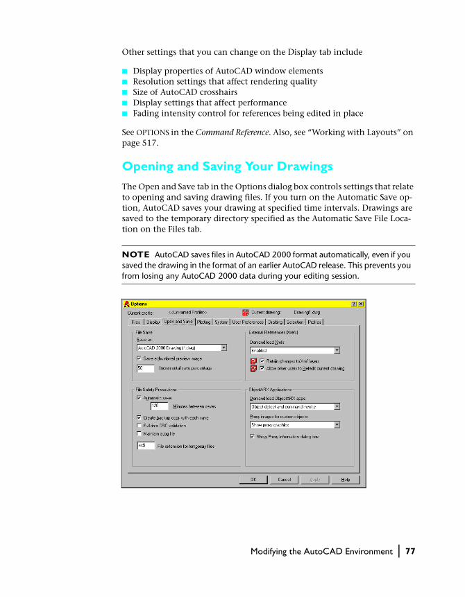
Opening and Saving Your Drawings
The Open and Save tab in the Options dialog box controls settings that relate to opening and saving drawing files. If you turn on the Automatic Save op-tion, AutoCAD saves your drawing at specified time intervals. Drawings are saved to the temporary directory specified as the Automatic Save File Loca-tion on the Files tab.
NOTE AutoCAD saves files in AutoCAD 2000 format automatically, even if you saved the drawing in the format of an earlier AutoCAD release. This prevents you from losing any AutoCAD 2000 data during your editing session.

78 | Chapter 3 Setting Up Your Drawing Environment
Other settings that you can change on the Open and Save tab include
■ Maintaining of log files ■ Saving of drawing preview image■ Cyclic Redundancy Checking (CRC) error-checking behavior■ Creating of backup drawings■ Behavior of external references■ Behaviors of ObjectARX applications and custom objects
See OPTIONS in the Command Reference.
Controlling Plotting Properties
Use the Plotting tab in the Options dialog box to set plotting options. You can specify general plotting controls such as the default plotting device, plot styles, and plot style behavior. A plot style is a collection of property settings that can be applied to different objects in the drawing.
Other settings that you can change on the Plotting tab include
■ Plotters and plotter configurations■ System warnings related to plotting■ Plotting behavior of OLE objects■ Plot style tables
See OPTIONS in the Command Reference. Also, see “Working with Layouts” on page 517 and chapter 16, “Plotting Your Drawings.”

Modifying the AutoCAD Environment | 79
Configuring System Options
Use the System tab in the Options dialog box to set the general AutoCAD sys-tem settings. For example, by default you can work with multiple documents in one session, but you can change AutoCAD to Single Document mode by selecting Single Drawing Compatibility Mode under General Options.
After you install AutoCAD, you usually do not need to perform additional configuration tasks for the mouse or digitizer, because AutoCAD uses the current system pointing device. However, you can change the current point-ing device and control whether AutoCAD accepts input from a digitizer only or from both a digitizer and a mouse.
Other settings that you can change on the System tab include
■ Use of long symbol names■ Startup dialog box display■ Behavior during user input errors■ LISP file-loading behavior■ OLE scale dialog box behavior■ Warning message display■ Database connectivity behavior■ 3D graphics display properties
See OPTIONS in the Command Reference.
80 | Chapter 3 Setting Up Your Drawing Environment
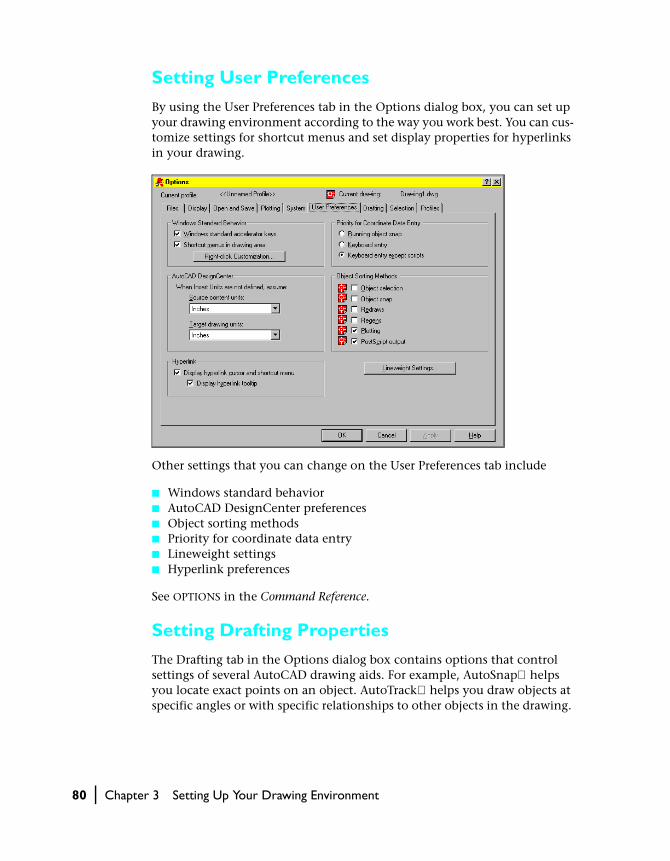
Setting User Preferences
By using the User Preferences tab in the Options dialog box, you can set up your drawing environment according to the way you work best. You can cus-tomize settings for shortcut menus and set display properties for hyperlinks in your drawing.
Other settings that you can change on the User Preferences tab include
■ Windows standard behavior■ AutoCAD DesignCenter preferences■ Object sorting methods■ Priority for coordinate data entry■ Lineweight settings■ Hyperlink preferences
See OPTIONS in the Command Reference.
Setting Drafting Properties
The Drafting tab in the Options dialog box contains options that control settings of several AutoCAD drawing aids. For example, AutoSnap helps you locate exact points on an object. AutoTrack helps you draw objects at specific angles or with specific relationships to other objects in the drawing.
Modifying the AutoCAD Environment | 81
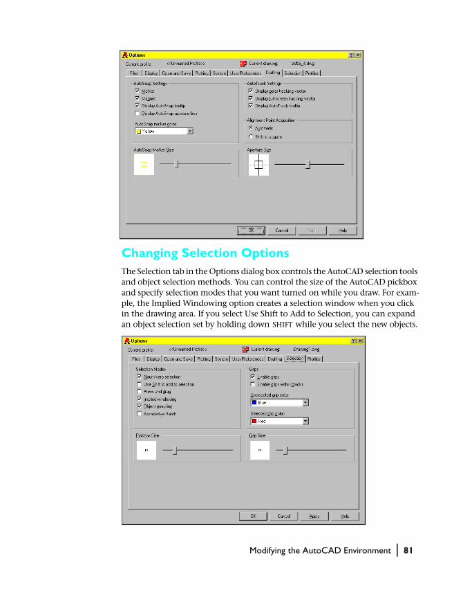
Changing Selection OptionsThe Selection tab in the Options dialog box controls the AutoCAD selection tools and object selection methods. You can control the size of the AutoCAD pickbox and specify selection modes that you want turned on while you draw. For exam-ple, the Implied Windowing option creates a selection window when you click in the drawing area. If you select Use Shift to Add to Selection, you can expand an object selection set by holding down SHIFT while you select the new objects.

82 | Chapter 3 Setting Up Your Drawing Environment
Other settings that you can change on the Selection tab include
■ Grip behavior and properties■ Press and drag selection■ Noun/verb selection■ Object grouping selection■ Associative hatch selection
See OPTIONS in the Command Reference.
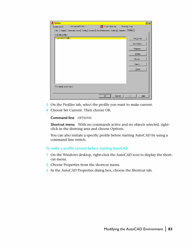
Creating Profiles
You can use the Profiles tab in the Options dialog box to create and save your drawing environment settings as a profile. If you share your workstation with other users who use the same login name, you can restore your options by making the profile current. You can also create and save profiles to use with different projects. By default, AutoCAD stores your current options in a pro-file named UNNAMED PROFILE. AutoCAD displays the current profile name, as well as the current drawing name, in the Options dialog box.
The profile information is stored in the system registry and can be saved toa text file (an ARG file). AutoCAD organizes essential data and maintains changes in the registry as necessary.
Once you save a profile, you can export or import the ARG file to and from different computers. If you make changes to your current profile during an AutoCAD session and you want to save those changes in the ARG file, you must export the profile. When you export the profile with the current profile name, AutoCAD updates the ARG file with the new settings. You can import the profile again into AutoCAD to update your profile settings.
To make a profile current
1 From the Tools menu, choose Options.
2 In the Options dialog box, choose the Profiles tab.
Modifying the AutoCAD Environment | 83
3 On the Profiles tab, select the profile you want to make current.
4 Choose Set Current. Then choose OK.
Command line OPTIONS
Shortcut menu With no commands active and no objects selected, right-click in the drawing area and choose Options.
You can also initiate a specific profile before starting AutoCAD by using a command line switch.
To make a profile current before starting AutoCAD
1 On the Windows desktop, right-click the AutoCAD icon to display the short-cut menu.
2 Choose Properties from the shortcut menu.
3 In the AutoCAD Properties dialog box, choose the Shortcut tab.
84 | Chapter 3 Setting Up Your Drawing Environment
4 Under Target, enter /p currentprofile after the current target directory. For example, to make the profile User12 current, enter the following in Target:
"c:\acad2000\acad.exe"/p user12
5 Choose OK to exit the dialog box.
The profile name you enter is the current profile each time you start AutoCAD.
For more information about profiles, see OPTIONS in the Command Reference. For more information about command line switches, see chapter 4, “Config-uring and Optimizing AutoCAD” in the Installation Guide.
Optimizing Performance
To optimize AutoCAD performance while working in a drawing, you can change certain settings in the Options dialog box. Keep in mind, however, that your drawing file size and system hardware play significant roles in AutoCAD performance.
The following settings on the Display tab in the Options dialog box affect performance:
■ Arc and Circle Smoothness: Set to a low value such as 100 for drawing and increase the value for rendering to optimize performance. The valid range is 1 through 20,000. When you increase the value, rendered objects are smoother; however, AutoCAD requires more time to regenerate, pan, and zoom.
■ Segments in a Polyline Curve: Set to a low value such as 4 to optimize per-formance. The higher the number of line segments, the more time is re-quired to regenerate the drawing.
■ Rendered Object Smoothness: Set to 1 or less to optimize performance. The valid range is 0.01 through 10. When you increase the value, display per-formance decreases and rendering time increases.
■ Contour Lines per Surface: Set to a low value such as 4 to optimize perfor-mance. The valid range is 0 through 2047. When you increase the value, display performance decreases and rendering time increases.
■ Pan and Zoom with Raster Image: Clear to optimize performance. During panning and zooming, AutoCAD displays only the frame of the raster image instead of the entire raster image.
■ Highlight Raster Image Frame Only: Select to optimize performance. Only the frame of the raster image, as opposed to the entire raster image, is highlighted when it is selected.
■ True Color Raster Images and Rendering: Clear to optimize performance. When AutoCAD displays images at optimum quality, regeneration time increases significantly. To improve performance while working in a
Modifying the AutoCAD Environment | 85
drawing, change the system display setting to decrease the number of colors.
■ Apply Solid Fill: Clear to optimize performance. Drawing regeneration time decreases because multilines, traces, solids, all hatches (including solid fill), and wide polylines are displayed as outlines, with no solid fill.
■ Show Text Boundary Frame Only: Select to optimize performance. Drawing regeneration time decreases because a boundary box is displayed instead of the actual text.
■ Show Silhouettes in Wireframe: Clear to optimize performance. When silhouette curves of body objects are not displayed, drawing regeneration time decreases.
The following settings on the Open and Save tab in the Options dialog box affect performance:
■ Save As: Set to an AutoCAD Drawing format to optimize performance. When you save an AutoCAD file to any DXFfile format, performance decreases when the drawing is saved.
■ Incremental Save Percentage: Set to 50 to optimize performance. AutoCAD saves only the changed drawing information until the amount of changed space is equal to the value set in this option. When AutoCAD performs a full save, the entire drawing is saved. When this option is set to 0, AutoCAD performs a full save every time. If you set this option to a low value, such as 20 or less, performance significantly decreases during a save.
■ Demand Load Xrefs: Set to Enabled to optimize performance. This option loads only the parts of the referenced drawing that are needed to regener-ate the current drawing. Use this option when working with clipped xrefs that contain a layer or spatial index.
The following setting on the System tab in the Options dialog box affects performance:
■ Store Links Index in Drawing File: Select to optimize performance during Link Select operations. Clear this option if you want to reduce the drawing file size or if you want to optimize opening drawings containing database tables.
The following setting on the Selection tab in the Options dialog box affects performance:
■ Enable Grips: Clear to optimize performance. A grip is a small square displayed on an object after you select it. When you select this option, drawing file size increases and regeneration time increases.
See OPTIONS in the Command Reference.
86 | Chapter 3 Setting Up Your Drawing Environment
Viewing and Updating Drawing Properties
You can track your drawings more easily by assigning properties to them. Drawing properties are details that help you identify the drawing, including title, author, subject, and keywords to identify the model or other impor-tant information. You can also store hyperlink addresses or directory paths and ten custom properties with your drawings.
To define drawing properties
1 From the File menu, choose Drawing Properties.
2 In the Drawing Properties dialog box, enter property information on the following tabs:
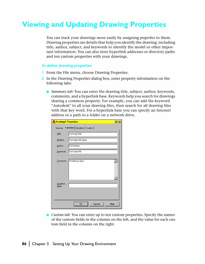
■ Summary tab: You can enter the drawing title, subject, author, keywords, comments, and a hyperlink base. Keywords help you search for drawings sharing a common property. For example, you can add the keyword “Autodesk” to all your drawing files, then search for all drawing files with that key word. For a hyperlink base you can specify an Internet address or a path to a folder on a network drive.
■ Custom tab: You can enter up to ten custom properties. Specify the names of the custom fields in the column on the left, and the value for each cus-tom field in the column on the right.

Viewing and Updating Drawing Properties | 87
3 Choose OK to exit the dialog boxes.
Command line DWGPROPS
You can use the Drawing Properties dialog box to view drawing information maintained by AutoCAD.
■ General tab: Displays the drawing type, location, size, and other informa-tion. The information is derived from the operating system. All fields are read-only. However, if you access file properties through Windows Explorer, the attributes options are made available by the operating system.
■ Statistics tab: Displays data such as file size and the dates files were created and last modified. You can search for all files created at a certain time, for example, after March 3, 1998, or files last modified yesterday.
NOTE Properties entered in the Drawing Properties dialog box are not associ-ated with the drawing until you save the drawing.
The Created, Modified, and Total Editing Time values are stored in the TDCREATE, TDINDWG, and TDUPDATE system variables.
88 | Chapter 3 Setting Up Your Drawing Environment
Modifying Toolbars
You can change the size of toolbar buttons and reposition, add, or delete tool-bar buttons. You can also change the toolbar name and turn tooltips on and off.
To modify a toolbar
1 From the View menu, choose Toolbars.
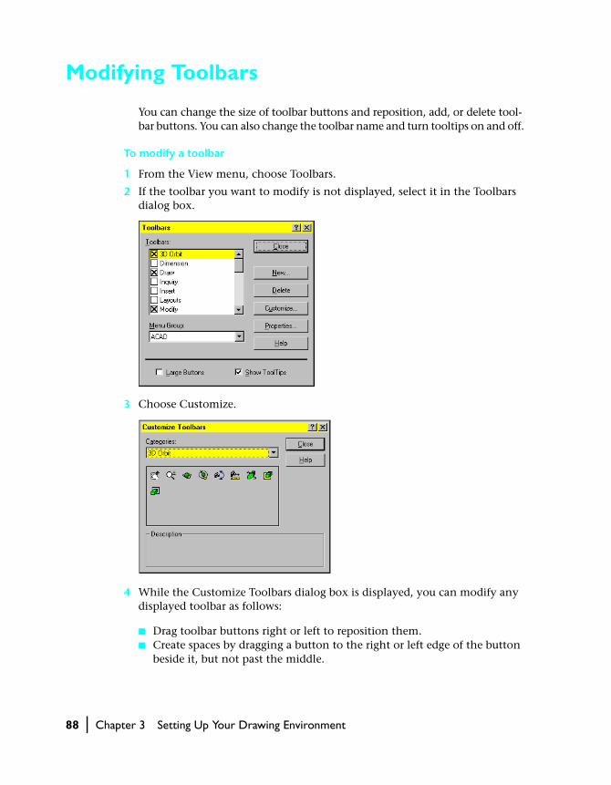
2 If the toolbar you want to modify is not displayed, select it in the Toolbars dialog box.
3 Choose Customize.
4 While the Customize Toolbars dialog box is displayed, you can modify any displayed toolbar as follows:
■ Drag toolbar buttons right or left to reposition them.■ Create spaces by dragging a button to the right or left edge of the button
beside it, but not past the middle.
Modifying Toolbars | 89
■ Remove toolbar buttons by dragging them off the toolbar.■ Add buttons to toolbars by dragging them from the Customize Toolbars
dialog box to the toolbar. Change the Categories selection to display the buttons you want to add.
■ Drag buttons from one toolbar to another, or press CTRL while you drag to copy the toolbar button to another toolbar.
5 Choose Close to exit the dialog boxes.
Command line TOOLBAR
Shortcut menu Right-click a toolbar and choose Customize.
To rename a toolbar
1 From the View menu, choose Toolbars.
2 In the Toolbars dialog box, select the toolbar name, and then choose Properties.
3 In the Toolbar Properties dialog box, enter a new name.
4 To change the text displayed on the status line, enter new text at Help, and then choose Apply.
5 In the Toolbars dialog box, choose Close.
To display tooltips
1 From the View menu, choose Toolbars.
2 In the Toolbars dialog box, select Show ToolTips and choose Close.
System variables TOOLTIPS turns tooltips on and off.
To change the size of buttons
1 From the View menu, choose Toolbars.
2 In the Toolbars dialog box, select Large Buttons and choose Close.
Creating and Deleting Toolbars
To create a new toolbar, you first create an empty toolbar, and then drag buttons onto the new toolbar from the Customize Toolbars dialog box or from other toolbars.
90 | Chapter 3 Setting Up Your Drawing Environment
To create a toolbar
1 From the View menu, choose Toolbars.
2 In the Toolbars dialog box, choose New.
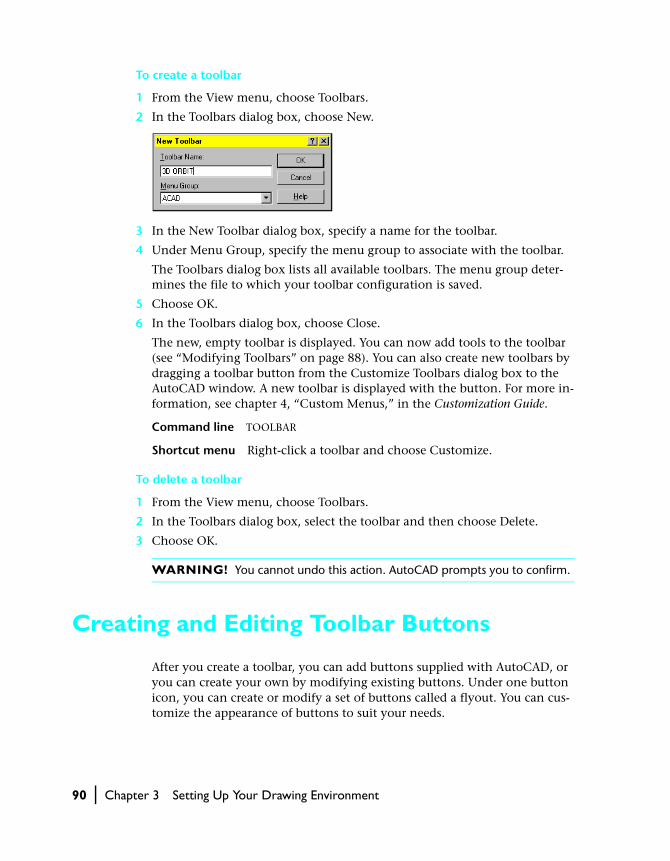
3 In the New Toolbar dialog box, specify a name for the toolbar.
4 Under Menu Group, specify the menu group to associate with the toolbar.
The Toolbars dialog box lists all available toolbars. The menu group deter-mines the file to which your toolbar configuration is saved.
5 Choose OK.
6 In the Toolbars dialog box, choose Close.
The new, empty toolbar is displayed. You can now add tools to the toolbar (see “Modifying Toolbars” on page 88). You can also create new toolbars by dragging a toolbar button from the Customize Toolbars dialog box to the AutoCAD window. A new toolbar is displayed with the button. For more in-formation, see chapter 4, “Custom Menus,” in the Customization Guide.
Command line TOOLBAR
Shortcut menu Right-click a toolbar and choose Customize.
To delete a toolbar
1 From the View menu, choose Toolbars.
2 In the Toolbars dialog box, select the toolbar and then choose Delete.
3 Choose OK.
WARNING! You cannot undo this action. AutoCAD prompts you to confirm.
Creating and Editing Toolbar Buttons
After you create a toolbar, you can add buttons supplied with AutoCAD, or you can create your own by modifying existing buttons. Under one button icon, you can create or modify a set of buttons called a flyout. You can cus-tomize the appearance of buttons to suit your needs.
Creating and Editing Toolbar Buttons | 91
Creating a Toolbar Button
AutoCAD commands are organized into categories in the Customize Toolbars dialog box. You can select a category to display a set of icons that represent a group of commands. AutoCAD also provides blank icons that you can assign to any command or macro.
Most commands begin with ̂ C^C to cancel a command that may be running and display the Command prompt. An underscore (_) enables commands to work on international versions of AutoCAD. An apostrophe (‘) enables the command to work in conjunction with another command. If you associate a series of commands with a button, separate them with semicolons or spaces. You create button macros the same way you create menu macros. For more information about entering commands in macros, see chapter 4, “Custom Menus,” in the Customization Guide.
To create a button
1 From the View menu, choose Toolbars.
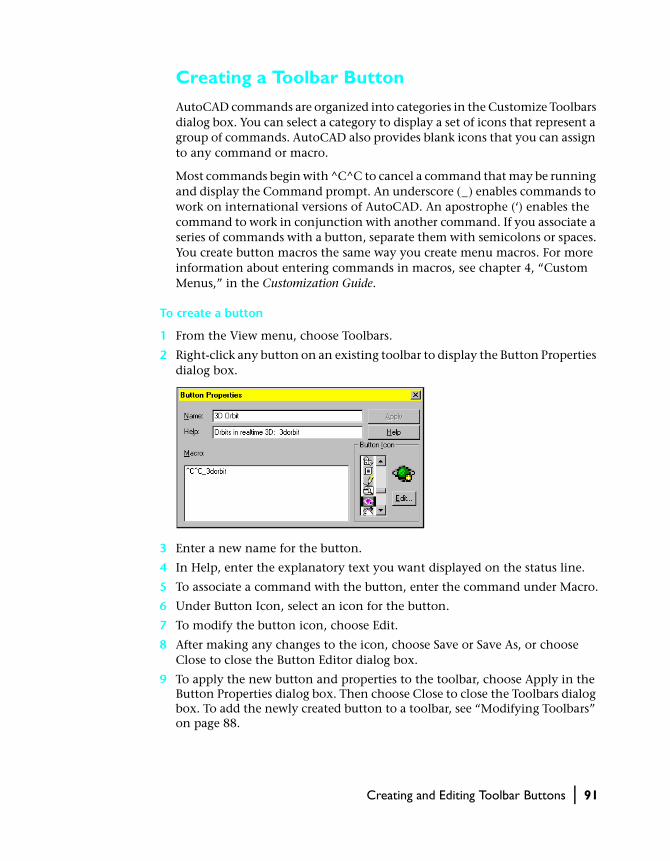
2 Right-click any button on an existing toolbar to display the Button Properties dialog box.
3 Enter a new name for the button.
4 In Help, enter the explanatory text you want displayed on the status line.
5 To associate a command with the button, enter the command under Macro.
6 Under Button Icon, select an icon for the button.
7 To modify the button icon, choose Edit.
8 After making any changes to the icon, choose Save or Save As, or choose Close to close the Button Editor dialog box.
9 To apply the new button and properties to the toolbar, choose Apply in the Button Properties dialog box. Then choose Close to close the Toolbars dialog box. To add the newly created button to a toolbar, see “Modifying Toolbars” on page 88.
92 | Chapter 3 Setting Up Your Drawing Environment
Changing the Command Assigned to a Button
In addition to changing a button associated with a command, you can change a command associated with a button.
To change a command
1 From the View menu, choose Toolbars.
2 Right-click the button you want to change.
3 In the Button Properties dialog box, edit the command information under Macro to specify a new command for the button.
4 Choose Apply.
5 In the Toolbars dialog box, choose Close.
Command line TOOLBAR
Shortcut menu Right-click a toolbar and choose Customize.
Creating a Flyout
A flyout is a set of buttons nested under a single flyout button on a toolbar. Flyout buttons are defined by a black triangle in the lower-right corner. To create a flyout, you create the flyout button and associate an existing toolbar with it.
To create a flyout
1 From the View menu, choose Toolbars.
2 In the Toolbars dialog box, choose Customize.
3 In the Customize Toolbars dialog box under Categories, select Custom.
4 Drag the flyout icon (a small black triangle) from the Customize Toolbars dialog box to the destination toolbar.
If you don’t have a destination toolbar, AutoCAD creates one when you drop the button anywhere except on another toolbar.
5 Right-click the newly created flyout button.
6 In the Flyout Properties dialog box under Associated Toolbar, select the tool-bar to associate with the flyout.

Creating and Editing Toolbar Buttons | 93
NOTE Always create a toolbar before you create a flyout. If you don’t asso-ciate a toolbar with the flyout button, AutoCAD issues a warning beep when you select the flyout button.
7 Under Button Icon, select an icon for the flyout.
You can modify the icon by choosing Edit to display the Button Editor. See the following section, “Editing Button Icons.”
8 To display the icon you specified, do one of the following:
■ Select Show This Button’s Icon: Displays the icon you specified for the flyout. When you click the flyout, AutoCAD starts the command represented by the first button on the toolbar you associated with this flyout.
■ Clear Show This Button’s Icon: Displays the first button on the toolbar you associated with this flyout until you use a different button from the flyout, when that button is displayed.
9 Choose Apply, and then close the dialog boxes.
Editing Button Icons
AutoCAD provides standard button icons to start commands. You can create custom icons to run custom macros. You can modify an existing icon or cre-ate your own. AutoCAD saves buttons as BMP (bitmap) files.
To edit or create a flyout icon
1 From the View menu, choose Toolbars.
2 Right-click a flyout on an existing toolbar to display the Flyout Properties dialog box.
3 In the Flyout Properties dialog box under Button Icon, select an icon and then choose Edit.

94 | Chapter 3 Setting Up Your Drawing Environment
The Button Editor dialog box provides a close-up view of the button icon. If you select Grid, AutoCAD divides the view into a grid. Each grid box repre-sents one pixel. The Button Editor dialog box displays the button icon at its actual size in the upper-left corner.
You can open an existing button using Open.
4 Use the Pencil, Line, Circle, and Erase tools to create or edit the button icon. To add color, select a color from the color palette.
■ Pencil button: Edits one pixel at a time in the selected color. You can drag the pointing device to edit several pixels at once.
■ Line button: Creates lines in the selected color.■ Circle button: Creates circles in the selected color.■ Erase button: Sets pixels to the background color when you drag the point-
ing device. Double-click the Erase button to set all pixels to the back-ground color.
5 To save the customized button, choose Save As, specify a file name, and choose Save. To overwrite the original button, choose Save.
6 Choose Close.
7 In the Flyout Properties dialog box, choose Apply.
8 In the Toolbars dialog box, choose Close.
button at actual size
colors
Pencil, Line, Circle, and Erase tools