ServoPod-USB™ - · PDF fileConnect the provided USB (A to B type) cable from the PC to...
22
ServoPod-USB™ User’s Manual
Transcript of ServoPod-USB™ - · PDF fileConnect the provided USB (A to B type) cable from the PC to...

ServoPod-USB™
User’s Manual

Warranty New Micros, Inc. warrants its products against defects in materials and workmanship for a period of 90 days. If you discover a defect, New Micros, Inc. will, at its option, repair, replace, or refund the purchase price. Simply call our sales department for an RMA number, write it on the label and return the product with a description of the problem. We will return your product, or its replacement, using the same shipping method used to ship the product to New Micros, Inc. (for instance, if you ship your product via overnight express, we will do the same). This warranty does not apply if the product has been modified or damaged by accident, abuse, or misuse.
Copyrights and Trademarks Copyright © 2002 by New Micros, Inc. All rights reserved. ServoPod-USB™, IsoMax™ and Virtually Parallel Machine Architecture™ are trademarks of New Micros, Inc. Windows is a registered trademark of Microsoft Corporation. 1-wire is a registered trademark of Dallas Semiconductor. Other brand and product names are trademarks or registered trademarks of their respective holders.
Disclaimer of Liability New Micros, Inc. is not responsible for special, incidental, or consequential damages resulting from any breach of warranty, or under any legal theory, including lost profits, downtime, goodwill, damage to or replacement of equipment or property, and any costs of recovering, reprogramming, or reproducing any data stored in or used with New Micros, Inc. products.
Internet Access Web site: http://www.newmicros.com This manual: http://www.newmicros.com/store/product_manual/ServoPod-USB.zip Email technical questions: [email protected] Email sales questions: [email protected]
Internet ServoPod-USB™ Discussion List We maintain the ServoPod-USB™ discussion list on our web site. Members can have all questions and answers forwarded to them. It’s a way to discuss ServoPod-USB™ issues. To subscribe to the ServoPod-USB™ list, visit the Discussion section of the New Micros, Inc. website. http://www.newmicros.com/discussion/ This manual is valid with the following software and firmware versions: IsoMax™ V 0.6 or newer. If you have any questions about what you need to upgrade your product, please contact New Micros, Inc.

GETTING STARTED Thank you for buying the ServoPod-USB™. We hope you will find the ServoPod-USB™ to be the incredibly useful small controller board we intended it to be, and easy to use as possible.
If you are new to the ServoPod-USB™, we know you will be in a hurry to see it working. Once we’ve got communications, then we can make some lights blink and know for sure we’re in business. Let’s make this “Pod” talk to us! First, you need to download and install the following driver and program on your PC, - Download the Virtual COM Port (VCP) USB driver from the link below, http://www.ftdichip.com/FTDriver.htm - Terminal Program, NMITerm http://www.newmicros.com/download/software/NMI/NMITerm.zip

Connect the provided USB (A to B type) cable from the PC to the ServoPod-USB™. All three LED’s should come on within a short delay after the USB cable is plugged in. If the LED’s don’t come on after more than a few seconds, unplug the USB cable quickly. Please see the trouble shooting section of this manual or contact NMI technical support for help, before going any further. As soon as the USB cable is plugged in, the PC will pop up the message: “ Found New Hardware”. It will ask to install the driver, usually when you install the driver for the first time. You can either let it automatically searches for the USB driver (make sure to unzip the file after downloading), or you can manually browse the window for the USB driver where it was downloaded and unzipped earlier. Once the FTDI USB driver is installed, you can open the communication program, NMITerm. The NMITerm program will open with the default configuration for 9600 baud, 8N1, and the COM port will be automatically detected. Keep in mind, you must first connect the USB cable prior to opening the terminal program in order for the NMITerm to recognize the USB COM port with auto detection. If NMITerm detects other available serial COM port instead of USB COM port, click on the NMITerm Options menu, Options>Settings>Serial COM Port, change the COM Port along with the new baud rate 115,200. Then click on APPLY, and OK buttons to save the new settings. If you are not sure which COM Port that is used by USB Serial, you can look up under: Start>Settings>Control Panel>System>Hardware>Device Manager>Ports(COM & LPT) If everything is setup correctly, pressing the reset button on the ServoPod-USB™ the terminal program should show “IsoMax™ Vx.x”, and each time you hit an Enter key the NMITerm will respond with “OK”. Seeing this message means the communication is established. Congratulations! Now let’s do something interactive with the ServoPod-USB™.
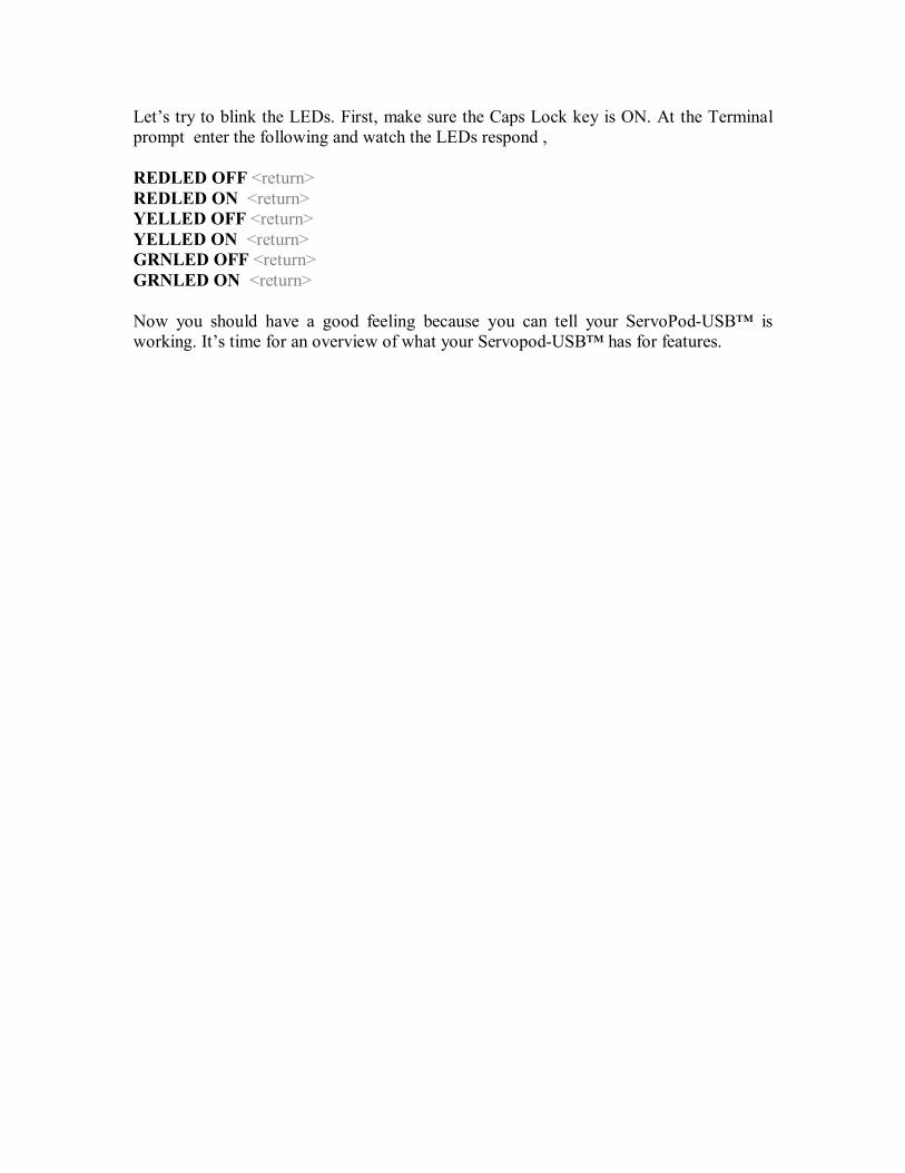
Let’s try to blink the LEDs. First, make sure the Caps Lock key is ON. At the Terminal prompt enter the following and watch the LEDs respond , REDLED OFF <return> REDLED ON <return> YELLED OFF <return> YELLED ON <return> GRNLED OFF <return> GRNLED ON <return> Now you should have a good feeling because you can tell your ServoPod-USB™ is working. It’s time for an overview of what your Servopod-USB™ has for features.

FEATURES • DSP56F807 MPU, 16-bit processor • Up to 40 MIPS at 80 MHZ core frequency • Memory & Configuration Modes
o Mode A (internal only) 60K x 16 Program Flash 2K x 16 Boot Flash 8K x 16 Data Flash 2K x 16 Program ram 4K x 16 Data Ram
o Mode B (internal & external combine) 32K x 16 Program Flash (internal) 2K x 16 Boot Flash (internal) 8K x 16 Data Flash (internal) 2K x 16 Program ram (internal) 32K x 16 Program ram (external) 4K x 16 Data Ram (internal) 48K x 16 Data Ram (external)
o Mode 3 (external only) - IsoMax does not support this mode. Assembly, C, Codewarrior, and other Third party compilers are supported. Jtag-cable-10P is required
64K x 16 Program Ram 64K x 16 Data Ram
Note: Mode 0 is included Mode A & B. Mode 1 & 2 is supported by other member of DSP56800 family, ROM-based MPU’s only.
• Two Serial Communication Interface, o Jumper configurations:
SCI0 default configures for USB Serial, and SCI1 for RS-232 or, Both SCI0 & SCI1 for Serial RS-232 interfaces
o Optional configurations below are only available per special request. SCI0 for USB, and SCI1 for TTL or RS-422/485 Or, SCI0 for RS-232, and SCI1 for TTL or RS-422/485
• Serial Peripheral Interface (SPI) • CAN 2.0 A/B module
o SN65HVD230, 3V CAN Transceiver o Multiple boards can be network (MSCAN) o Ideal for harsh or noisy environments, like automotive applications
• Programmable bit rate up to 1Mbit • Up to 22 GPIO lines, atleast 10 are shared with external memory
address/data lines • Two 8-channel 12-bit ADCs
o Single Conversion is 1.7us (8.5 ADC cycles) o Continuous Conversion is 1.2us (6 ADC cycles) o Simultaneous conversion on each ADC o Single ended or differential inputs o Signed or unsigned results o ADC can be sync’d with PWM o Optional interrupts:
at end of scan
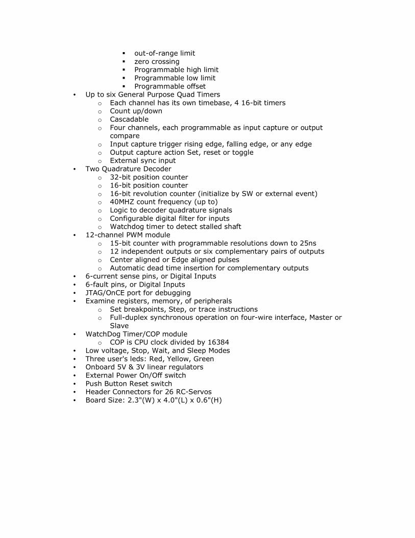
out-of-range limit zero crossing Programmable high limit Programmable low limit Programmable offset
• Up to six General Purpose Quad Timers o Each channel has its own timebase, 4 16-bit timers o Count up/down o Cascadable o Four channels, each programmable as input capture or output
compare o Input capture trigger rising edge, falling edge, or any edge o Output capture action Set, reset or toggle o External sync input
• Two Quadrature Decoder o 32-bit position counter o 16-bit position counter o 16-bit revolution counter (initialize by SW or external event) o 40MHZ count frequency (up to) o Logic to decoder quadrature signals o Configurable digital filter for inputs o Watchdog timer to detect stalled shaft
• 12-channel PWM module o 15-bit counter with programmable resolutions down to 25ns o 12 independent outputs or six complementary pairs of outputs o Center aligned or Edge aligned pulses o Automatic dead time insertion for complementary outputs
• 6-current sense pins, or Digital Inputs • 6-fault pins, or Digital Inputs • JTAG/OnCE port for debugging • Examine registers, memory, of peripherals
o Set breakpoints, Step, or trace instructions o Full-duplex synchronous operation on four-wire interface, Master or
Slave • WatchDog Timer/COP module
o COP is CPU clock divided by 16384 • Low voltage, Stop, Wait, and Sleep Modes • Three user's leds: Red, Yellow, Green • Onboard 5V & 3V linear regulators • External Power On/Off switch • Push Button Reset switch • Header Connectors for 26 RC-Servos • Board Size: 2.3"(W) x 4.0"(L) x 0.6"(H)

INTRODUCTION What is neat about the ServoPod-USB™? Several things. First it is a very good micro controller. There is no need for an additional power supply to power the micro-controller for program development other than an USB cable connects from your PC or laptop to the ServoPod-USB™. The ServoPod-USB™ can steal the power directly from the PC or laptop via USB cable. The ServoPod-USB™ was intended to be as small as possible, while still being useable. A careful balance between dense features, and access to connections is made here. Feature density is very high. So secondly, having connectors you can actually “get at” is also a big plus. What is the use of a neat little computer with lots of features, if you can conveniently only use one of those features at a time? The answer is very important. The neatest thing about the ServoPod-USB™ is software giving Virtually Parallel Machine Architecture! Virtually Parallel Machine Architecture (VPMA) is a new programming paradigm. VPMA allows small, independent machines to be constructed, then added seamlessly to the system. All these installed machines run in a virtually parallel fashion.
In an ordinary high level language, such as C, Basic, Forth or Java, most anyone can make a small computer do one thing well. Programs are written flowing from top to bottom. Flow charts are the preferred diagramming tools for these languages. Any time a program must wait on something, it simply loops in place. Most conventional languages follow the structured procedural programming paradigm. Structured programming enforces this style.
Getting two things done at the same time gets tricky. Add a few more things concurrently competing for processor attention, and most projects start running into serious trouble. Much beyond that, and only the best programmers can weave a program together running many tasks in one application. Most of us have to resort to a multitasking system. (Windows and Linux are the most obvious examples of multitasking systems.) For a dedicated processor, a multitasking operating system adds a great amount of overhead for each task and an unpleasant amount of program complexity.
The breakthrough in IsoMax™ is the language is inherently “multitasking” without the overhead or complexity of a multitasking operating system. There’s really been nothing quite like it before. Anyone can write a few simple machines in IsoMax™ and string them together so they work.

Old constrained ways of thinking must be left behind to get this new level of efficiency. IsoMax™ is therefore not, and cannot be, like a conventional procedural language. Likewise, conventional languages cannot become IsoMax™ like without loosing a number of key features which enforces Structured Programming at the expense of Isostructure.
In IsoMax™, all tasks are handled on the same level, each running like its own separate little machine. (Tasks don’t come and go, like they do in multitasking, any more than you’d want your leg to come and go while you’re running.) Each machine in the program is like hardware component in a mechanical solution. Parts are installed in place, each associated with their own place and function. Programming means create a new processor task fashioned as a machine, and debug it interactively in the foreground. When satisfied with performance, you install the new machine in a chain of machines. The machine chain becomes a background feature of the ServoPod-USB™ until you remove it or replace it. The combination of VPMA software and diverse hardware makes ServoPod-USB™ very versatile. It can be used as a stand-alone computer board, deeply embedded inside some project. It can be the controller on a larger PCB board. An ServoPod-USB™ brings an amazing amount power to a very small space, at a very reasonable cost. You’ll undoubtedly want to have a few ServoPod-USB™ ‘s on hand for your future projects.

QUICK TOUR Start by comparing your board to the diagram below. Most of the important features on the top board are labeled.
The table below gives a brief description of each connector, jumper and the signals involved.
J1 SCI0, Power, General Purpose I/O Serial, Power, Ports PA0 – PA7, PB0 – PB7 J2 SCI 1, CAN RS232(or RS422/485), and CANH, CANL J3 SPI/GPIO’s SCLK, MISO, MOSI, SS, PE2, PE3, RSTO J4 Alternate Power Input Connector Vin & Ground, Controller Power Inputs J5 A/D 0 to 7 First 8 ADC channels J6 A/D 8 to 15 Second 8 ADC channels J7 Fault and Status for PWM FaultA0-3, FaultB0-3, ISA0-2, ISB0-2 J8 JTAG JTAG Interface J9 PWM pins PWMA0-5, PWMB0-5 J10 Motor Encoder x 2/Timers Phase A, B, Index, Home x 2(or TA0-3,TB0-3) J11 Timers and Interrupts TC0, TC1, TD0-3, IRQA, IRQB J12 Two wire handshaking RTS, CTS handshaking signals, RI wakeups J13 Controller powers selection uP powers by USB bus or external supply J14 External Memory Disable/Enable External Ram Chip select Disable/Enable J15 SCI0 USB/RS-232 selection USB transmitter/RS-232 Receiver selection J16 USB chip Self/Bus powered USB powers by USB bus or external supply J17 Alternate Servo Power Input Con. +V & GND J18 Alternate Servo Power Input Con. +V & GND J19 Alternate Servo Power Input Con. +V & GND J20 Internal Memory Disable/Enable Boot from Internal or External Memory

CONNECTOR PIN ASSIGNMENTS J1, POWER, SERIAL, GPIO’s
+VIN 1 2 SOUT GND 3 4 SIN RST’ 5 6 ATN’ +5V 7 8 GND PA0 9 10 PB0 PA1 11 12 PB1 PA2 13 14 PB2 PA3 15 16 PB3 PA4 17 18 PB4 PA5 19 20 PB5 PA6 21 22 PB6 PA7 23 24 PB7
Note: In picture above, Pin 1 is at upper left viewing CPU side with J1 at left. This connector pin out and pin numbering scheme is unique to this one instance. Origin of pin out and numbering is to match stamp-like connection pin outs.
J3, SPI – GPIO’s +5V 1 2 GND +3V 3 4 SCLK
RSTO 5 6 MOSI PE2 7 8 MISO PE3 9 10 SS’
J2, CAN – RS-232(or 422/485) RxD1/+XMT 1 2 +3V TxD1/-XMT 3 4 GND
GND 5 6 CANL SIN1/-RCV 7 8 GND SOUT1/+RCV 9 10 CANH
J5, ADC 0-7 VSSA ANA1 ANA3 ANA5 ANA7
2 4 6 8 10 1 3 5 7 9
VREF ANA0 ANA2 ANA4 ANA6
J6, ADC 8-15 VSSA ANA9 ANA11 ANA13. ANA15
2 4 6 8 10 1 3 5 7 9
VREF2 ANA8 ANA10 ANA12 ANA14
J7, Various Inputs+3V ISA0 ISA1 ISA2 ISB0 ISB1 ISB2 GND
2 4 6 8 10 12 14 16 1 3 5 7 9 11 13 15
FA0 FA1 FA2 FA3 FB0 FB1 FB2 FB3 FAx: FAULT0-3 , FBx: FAULTB0-3

J9, PWM Servo Output
Sig. +V GND PWMA0 1 2 3 PWMA1 4 5 6 PWMA2 7 8 9 PWMA3 10 11 12 PWMA4 13 14 15 PWMA5 16 17 18 PWMB0 19 20 21 PWMB1 22 23 24 PWMB2 25 26 27 PWMB3 28 29 30 PWMB4 31 32 33 PWMB5 34 35 36
J10, Motor Encoder/Timers
Sig. Power Power +5V 1 2 +V 3 +3V
GND 4 5 GND 6 GND PH A 0/TA0 7 8 +V 9 GND PH B 0/TA1 10 11 +V 12 GNDIND 0/TA2 13 14 +V 15 GNDHM 0/TA3 16 17 +V 18 GND
+5V 19 20 +V 21 +3 VGND 22 23 GND 24 GND
PH A 1/TB0 25 26 +V 27 GNDPH B 1/TB1 28 29 +V 30 GNDIND 1/TB2 31 32 +V 33 GNDHM 1/TB3 34 35 +V 36 GND
J8, JTAG J11, Timers & IRQ
J12, Handshaking Signals
J4, Alt. Controller Power Input 1 2 VIN GND
J17, Servo Power Input 1 2 +V GND
J18, Servo Power Input 1 2 +V GND
J19, Servo Power Input 1 2 +V GND
+3V 1 2 GND TDI 3 4 GND TDO 5 6 TMS TCK 7 8 DE
RESET 9 10 TRST
Sig. Power Power +5V 1 2 +V 3 +3V GND 4 5 GND 6 GND TC0 7 8 +V 9 GND TC1 10 11 +V 12 GND
IRQA 13 14 +V 15 GNDIRQB 16 17 +V 18 GND+5V 19 20 +V 21 +3V GND 22 23 GND 24 GNDTD0 25 26 +V 27 GNDTD1 28 29 +V 30 GNDTD2 31 32 +V 33 GNDTD3 34 35 +V 36 GND
2 PD0 4 PD1 6 GND 8 PD2 1 RTS 3 CTS 5 CTS 7 RI
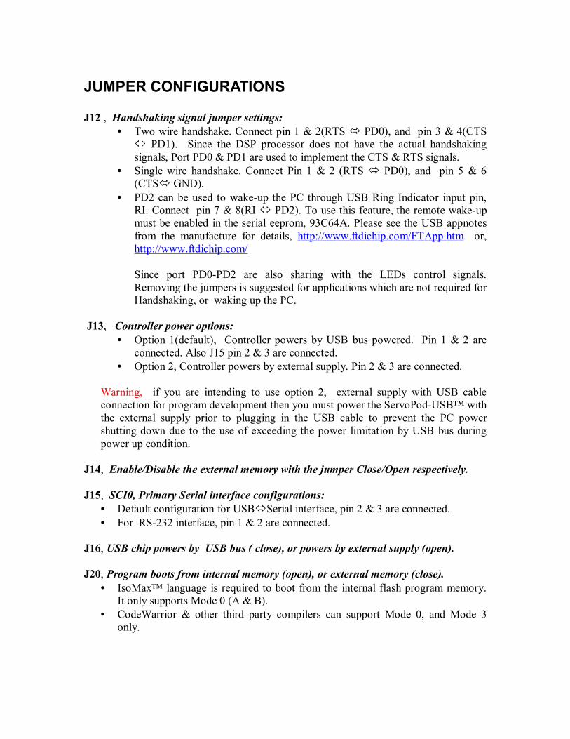
JUMPER CONFIGURATIONS J12 , Handshaking signal jumper settings:
• Two wire handshake. Connect pin 1 & 2(RTS PD0), and pin 3 & 4(CTS PD1). Since the DSP processor does not have the actual handshaking
signals, Port PD0 & PD1 are used to implement the CTS & RTS signals. • Single wire handshake. Connect Pin 1 & 2 (RTS PD0), and pin 5 & 6
(CTS GND). • PD2 can be used to wake-up the PC through USB Ring Indicator input pin,
RI. Connect pin 7 & 8(RI PD2). To use this feature, the remote wake-up must be enabled in the serial eeprom, 93C64A. Please see the USB appnotes from the manufacture for details, http://www.ftdichip.com/FTApp.htm or, http://www.ftdichip.com/
Since port PD0-PD2 are also sharing with the LEDs control signals. Removing the jumpers is suggested for applications which are not required for Handshaking, or waking up the PC.
J13, Controller power options:
• Option 1(default), Controller powers by USB bus powered. Pin 1 & 2 are connected. Also J15 pin 2 & 3 are connected.
• Option 2, Controller powers by external supply. Pin 2 & 3 are connected. Warning, if you are intending to use option 2, external supply with USB cable connection for program development then you must power the ServoPod-USB™ with the external supply prior to plugging in the USB cable to prevent the PC power shutting down due to the use of exceeding the power limitation by USB bus during power up condition.
J14, Enable/Disable the external memory with the jumper Close/Open respectively. J15, SCI0, Primary Serial interface configurations:
• Default configuration for USB Serial interface, pin 2 & 3 are connected. • For RS-232 interface, pin 1 & 2 are connected.
J16, USB chip powers by USB bus ( close), or powers by external supply (open). J20, Program boots from internal memory (open), or external memory (close).
• IsoMax™ language is required to boot from the internal flash program memory. It only supports Mode 0 (A & B).
• CodeWarrior & other third party compilers can support Mode 0, and Mode 3 only.
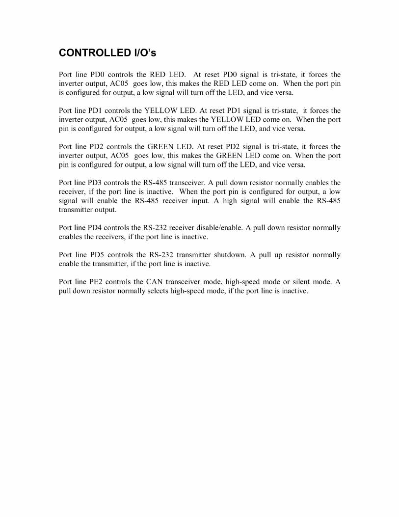
CONTROLLED I/O’s Port line PD0 controls the RED LED. At reset PD0 signal is tri-state, it forces the inverter output, AC05 goes low, this makes the RED LED come on. When the port pin is configured for output, a low signal will turn off the LED, and vice versa. Port line PD1 controls the YELLOW LED. At reset PD1 signal is tri-state, it forces the inverter output, AC05 goes low, this makes the YELLOW LED come on. When the port pin is configured for output, a low signal will turn off the LED, and vice versa. Port line PD2 controls the GREEN LED. At reset PD2 signal is tri-state, it forces the inverter output, AC05 goes low, this makes the GREEN LED come on. When the port pin is configured for output, a low signal will turn off the LED, and vice versa. Port line PD3 controls the RS-485 transceiver. A pull down resistor normally enables the receiver, if the port line is inactive. When the port pin is configured for output, a low signal will enable the RS-485 receiver input. A high signal will enable the RS-485 transmitter output. Port line PD4 controls the RS-232 receiver disable/enable. A pull down resistor normally enables the receivers, if the port line is inactive. Port line PD5 controls the RS-232 transmitter shutdown. A pull up resistor normally enable the transmitter, if the port line is inactive. Port line PE2 controls the CAN transceiver mode, high-speed mode or silent mode. A pull down resistor normally selects high-speed mode, if the port line is inactive.
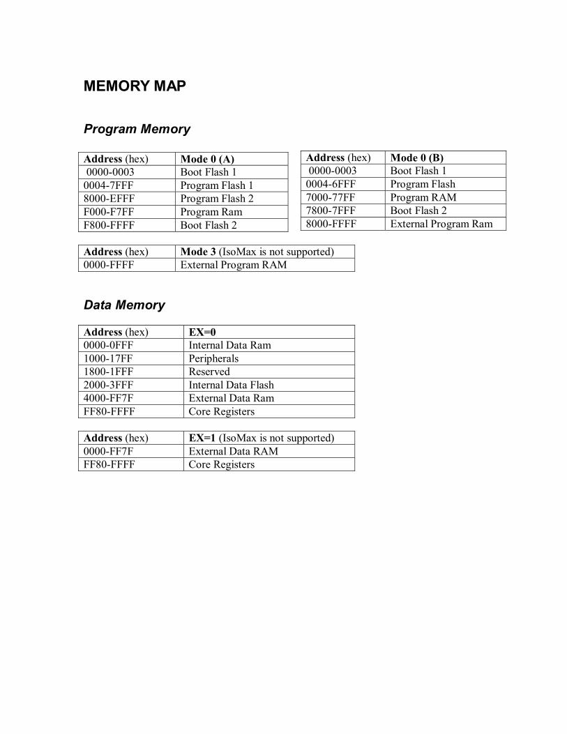
MEMORY MAP
Program Memory Address (hex) Mode 0 (A) 0000-0003 Boot Flash 1 0004-7FFF Program Flash 1 8000-EFFF Program Flash 2 F000-F7FF Program Ram F800-FFFF Boot Flash 2 Address (hex) Mode 3 (IsoMax is not supported) 0000-FFFF External Program RAM Data Memory Address (hex) EX=0 0000-0FFF Internal Data Ram 1000-17FF Peripherals 1800-1FFF Reserved 2000-3FFF Internal Data Flash 4000-FF7F External Data Ram FF80-FFFF Core Registers Address (hex) EX=1 (IsoMax is not supported) 0000-FF7F External Data RAM FF80-FFFF Core Registers
Address (hex) Mode 0 (B) 0000-0003 Boot Flash 1 0004-6FFF Program Flash 7000-77FF Program RAM 7800-7FFF Boot Flash 2 8000-FFFF External Program Ram

DATA MEMORY PERIPHERAL REGISTER ADDRESS Address Range (hex) Base Address (hex) 1000-100F SYS_BASE=1000 1010-10FF Reserved 1100-111F TmrA_BASE=1100 1120-113F TmrB_BASE=1120 1140-115F TmrC_BASE=1140 1160-117F TmrD_BASE=1160 1180-11FF CAN_BASE=1180 1200-121F PWMA_BASE=1200 1220-123F PWMB_BASE=1220 1240-124F DEC0_BASE=1240 1250-125F DEC1_BASE=1250 1260-127F ITCN_BASE=1260 1280-12BF ADCA_BASE=1280 12C0-12FF ADCB_BASE=12C0 1300-130F SCI0_BASE=1300 1310-131F SCI1_BASE=1310 1320-132F SPI_BASE=1320 1330-133F COP_BASE=1330 1340-135F PFIU_BASE=1340 1360-137F DFIU_BASE=1360 1380-139F BFIU_BASE=1380 13A0-13AF CLKGEN_BASE=13A0 13B0-13BF GPIOA_BASE=13B0 13C0-13CF GPIOB_BASE=13C0 13D0-13DF Reserved 13E0-13EF GPIOD_BASE=13E0 13F0-13FF GPIOE_BASE=13F0 1420-143F PFIU2_BASE=1420
For more detail about each individual register address, please see the DSP56F80x User’s Manual link below, http://www.freescale.com/files/dsp/doc/user_guide/DSP56F801-7UM.pdf

Instructions for Wiring a Serial Cable on J1 Connector To use this option, RS-232 interface on SCI0. J15 must jumper on pin 1 & 2
Transformer hook up Serial Cable hook up Black w/Striped
White +VIN 1 2 SOUT
Solid Black GND 3 4 SIN RST’ 5 6 ATN’ +5V 7 8 GND PA0 9 10 PB0 PA1 11 12 PB1 PA2 13 14 PB2 PA3 15 16 PB3 PA4 17 18 PB4 PA5 19 20 PB5 PA6 21 22 PB6 PA7 23 24 PB7
+VIN 1 2 SOUT RED GND 3 4 SIN ORANGE RST’ 5 6 ATN’YELLOW+5V 7 8 GND GREEN PA0 9 10 PB0 PA1 11 12 PB1 PA2 13 14 PB2 PA3 15 16 PB3 PA4 17 18 PB4 PA5 19 20 PB5 PA6 21 22 PB6 PA7 23 24 PB7
J1 Pin Preferred Color DB-9 Pin DB-25 Pin 2 SOUT RED 2 RX 3 TX
4 SIN ORANGE 3 TX 2 RX 6 ATN YELLOW 4 DTR 20 DTR 8 GND GREEN 5 GND 7 GND
6 DSR 6 DSR 7 RTS 20 RTS

TROUBLE SHOOTING There are no user serviceable parts on the ServoPod-USB™. If connections are made correctly, operation should follow, or there are serious problems on the board. As always, the first thing to check in case of trouble is checking power and ground are present. Measuring these with a voltmeter can save hours of head scratching from overlooking the obvious. After power and ground, signal connections should be checked next. If the serial cable comes loose, on either end, using your PC to debug your program just won’t help. Also, if your terminal program has locked up, you can experience some very “quiet” results. Don’t overlook these sources of frustrating delays when looking for a problem. They are easy to check, and will make a monkey of you more times than not, if you ignore them. One of the great advantages of having an interactive language embedded in a processor, is if communications can be established, then program tools can be built to test operations. If the RS-232 channel is not in use in your application, or if it can be optionally assigned to debugging, talking to the board through the language will provide a wealth of debugging information. The LED’s can be wonderful windows to show operation. This takes some planning in design of the program. A clever user will make good use of these little light. Even if the RS-232 channel is in use in your application and not available for debugging, don’t overlook the LED’s as a way to follow program execution looking for problems. The ServoPod-USB™ is designed so no soldering to the board should be required, and the practice of soldering to the board is not recommended. Instead, all signals are brought to connectors. That’s one of the reasons it is called a “Pod”, it can be plugged in and pulled out as a module. So, the best trouble shooting technique would be to unplug the ServoPod-USB™ and try to operate it separately with a known good serial cable on power supply. If the original connections have been tested to assure no out-of-range voltages are present, a second ServoPod-USB™ can then be programmed and plugged into the circuit in question. But don’t be too anxious to take this step. If the first ServoPod-USB™ should be burned out, you really want to be sure you know what caused it, before sacrificing another one in the same circuit. Finally, for advanced users, the JTAG connection can give trace, single step and memory examination information with the use of special debugging hardware. This level of access is beyond the expected average user of the ServoPod-USB™ and will not be addressed in this manual.

NMITerm Provided Windows terminal program from New Micros, Inc. Usually provided in a ZIP. Un ZIP in a subdirectory, such as C:\NMITerm. To start the program: click, or double click, the program icon.
NMITerm.LNK NMITerm is a simple Windows-based communications package designed for program development on serial port based embedded controllers. It runs under Windows. NMITerm provides: 1. Support for COM1 through COM16. 2. Baud rates from 110 through 256000. 3. Control over RTS and DTR lines. 4. Capture files, which record all terminal activity to disk. 5. Scroll-back buffer, editable and savable as a file. 6. On-line Programmer's Editor. 7. File downloader. 8. Programmable function keys. Quick start commands:
Baud: default 9600 DTR On/Off : ALT+T Download: ALT+D For further information use the Help screen. This program can be downloaded from: http://www.newmicros.com/download/software/NMI/NMITerm.zip
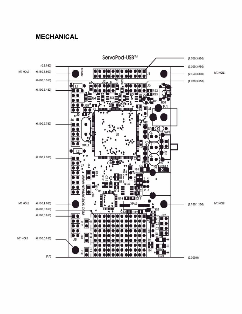
MECHANICAL
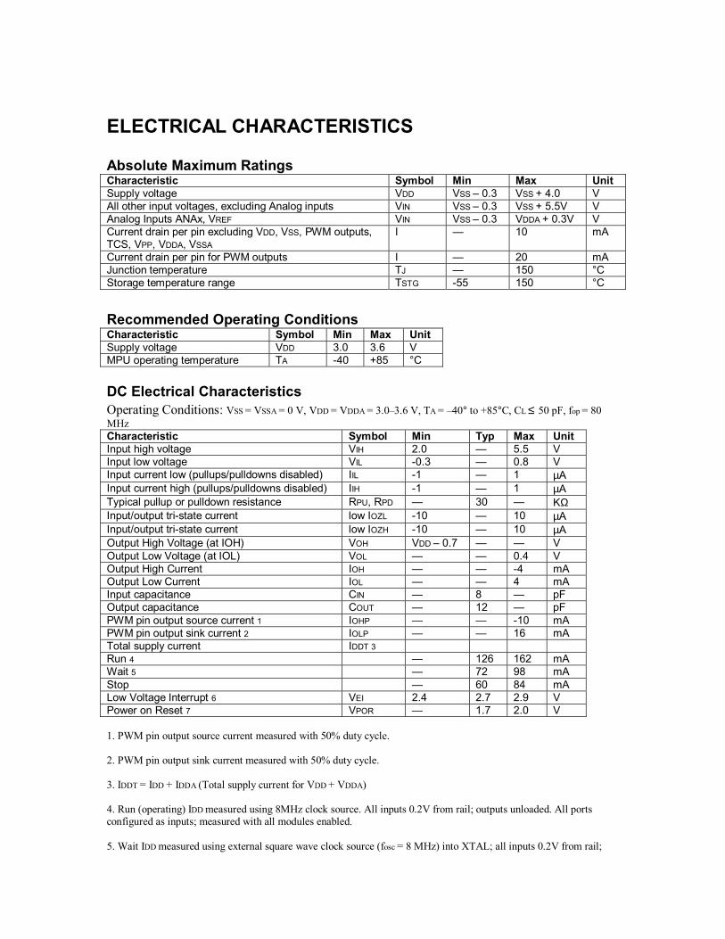
ELECTRICAL CHARACTERISTICS Absolute Maximum Ratings Characteristic Symbol Min Max Unit Supply voltage VDD VSS – 0.3 VSS + 4.0 V All other input voltages, excluding Analog inputs VIN VSS – 0.3 VSS + 5.5V V Analog Inputs ANAx, VREF VIN VSS – 0.3 VDDA + 0.3V V Current drain per pin excluding VDD, VSS, PWM outputs, TCS, VPP, VDDA, VSSA
I — 10 mA
Current drain per pin for PWM outputs I — 20 mA Junction temperature TJ — 150 °C Storage temperature range TSTG -55 150 °C
Recommended Operating Conditions Characteristic Symbol Min Max Unit Supply voltage VDD 3.0 3.6 V MPU operating temperature TA -40 +85 °C DC Electrical Characteristics Operating Conditions: VSS = VSSA = 0 V, VDD = VDDA = 3.0–3.6 V, TA = –40° to +85°C, CL ≤ 50 pF, fop = 80 MHz Characteristic Symbol Min Typ Max Unit Input high voltage VIH 2.0 — 5.5 V Input low voltage VIL -0.3 — 0.8 V Input current low (pullups/pulldowns disabled) IIL -1 — 1 µA Input current high (pullups/pulldowns disabled) IIH -1 — 1 µA Typical pullup or pulldown resistance RPU, RPD — 30 — KΩ Input/output tri-state current low IOZL -10 — 10 µA Input/output tri-state current low IOZH -10 — 10 µA Output High Voltage (at IOH) VOH VDD – 0.7 — — V Output Low Voltage (at IOL) VOL — — 0.4 V Output High Current IOH — — -4 mA Output Low Current IOL — — 4 mA Input capacitance CIN — 8 — pF Output capacitance COUT — 12 — pF PWM pin output source current 1 IOHP — — -10 mA PWM pin output sink current 2 IOLP — — 16 mA Total supply current IDDT 3 Run 4 — 126 162 mA Wait 5 — 72 98 mA Stop — 60 84 mA Low Voltage Interrupt 6 VEI 2.4 2.7 2.9 V Power on Reset 7 VPOR — 1.7 2.0 V 1. PWM pin output source current measured with 50% duty cycle. 2. PWM pin output sink current measured with 50% duty cycle. 3. IDDT = IDD + IDDA (Total supply current for VDD + VDDA) 4. Run (operating) IDD measured using 8MHz clock source. All inputs 0.2V from rail; outputs unloaded. All ports configured as inputs; measured with all modules enabled. 5. Wait IDD measured using external square wave clock source (fosc = 8 MHz) into XTAL; all inputs 0.2V from rail;

no DC loads; less than 50 pF on all outputs. CL = 20 pF on EXTAL; all ports configured as inputs; EXTAL capacitance linearly affects wait IDD; measured with PLL enabled. 6. Low voltage interrupt monitors the VDDA supply. When VDDA drops below VEI value, an interrupt is generated. For correct operation, set VDDA=VDD. Functionality of the device is guaranteed under transient conditions when VDDA>VEI. 7. Power-on reset occurs whenever the internally regulated 2.5V digital supply drops below VPOR. While power is ramping up, this signal remains active for as long as the internal 2.5V supply is below 1.5V no matter how long the ramp up rate is. The internally regulated voltage is typically 100 mV less than VDD during ramp up until 2.5V is reached, at which time it self regulates.