Servo Controller SE-24 - afag.com · SE-24-CANopen-Manual vers. 1.2 en. 02.04.2012 3 Symbols:...
24
Servo Controller SE-24 CANopen Manual Complementary document to the Operating Manual © Copyright by Afag Automation AG
Transcript of Servo Controller SE-24 - afag.com · SE-24-CANopen-Manual vers. 1.2 en. 02.04.2012 3 Symbols:...

Servo Controller
SE-24
CANopen Manual
Complementary document to the
Operating Manual © Copyright by Afag Automation AG

2 SE-24-CANopen-Manual vers. 1.2 en. 02.04.2012
This manual is a complementary document to the operating manual and applies to:
Type Order No.
SE-24 CANopen 50315437
Assembly and initial start-up must only be carried out by qualified personnel and according to these operating instructions.
Version of this
documentation: SE-24-CANopen-Manual vers. 1.2 en. 02.04.2012
CAUTION
As this manual is a complementary document to the operating instructions, it is not sufficient alone to carry out installation and commissioning of the device.
Please pay attention to the notes in
1.1 Documentation

SE-24-CANopen-Manual vers. 1.2 en. 02.04.2012 3
Symbols:
DANGER
Indicates imminent danger.
Non-compliance with this information results in death or serious personal injuries (invalidity).
WARNING
Indicates a possible dangerous situation.
Non-compliance with this information results in death or serious personal injuries (invalidity).
CAUTION
Indicates a possible dangerous situation.
Non-compliance with this information results in damage to property or slight to moderate personal injuries.
NOTE
Indicates general notes, useful operator tips and operating recommendations which do not affect safety and health of the personnel.

4 SE-24-CANopen-Manual vers. 1.2 en. 02.04.2012
Table of Contents
1 General .............................................................................................................. 6
1.1 Documentation ............................................................................................................................... 6
2 Safety instructions ........................................................................................... 7
3 CAN Bus ............................................................................................................ 8
3.1 CANopen ........................................................................................................................................ 8
3.2 Objects ........................................................................................................................................... 9
3.3 Documentation about CAN and CANopen .................................................................................. 10
4 Wiring and pin assignment ............................................................................ 11
4.1 Pin assignment............................................................................................................................. 11
4.1.2 Bus cable for CANopen ............................................................................................................... 12 4.1.3 Termination and bus terminating resistors ................................................................................... 13
5 CAN interface connection .............................................................................. 14
5.1 Introduction .................................................................................................................................. 14
5.2 Setting CAN parameters (Node-ID and Baud Rate) .................................................................... 14
5.3 Baud rate ...................................................................................................................................... 14
5.4 Control .......................................................................................................................................... 15
5.4.1 Status register (actual values) ..................................................................................................... 16 5.4.2 Control register (target values) .................................................................................................... 18
5.5 Integration in a PLC ..................................................................................................................... 21
6 Signal diagram ................................................................................................ 22

SE-24-CANopen-Manual vers. 1.2 en. 02.04.2012 5
List of Figures
Figure 1: View of the connection [X2a] ...................................................................................................11
Figure 2: View of the connection [X3a] ...................................................................................................11

6 SE-24-CANopen-Manual vers. 1.2 en. 02.04.2012
1 General
1.1 Documentation
This manual is a complementary documentation to the operating manual and describes the field bus interface connection of the SE-24 servo controller under CANopen. It contains a description of setting the physical parameters and communication with the servo controller.
It is intended for persons who are already familiar with the SE-24 servo controller.
It contains safety instructions that must be followed.
More detailed information can be found in the following documents:
Main document:
SE-24 Operating Manual
Description of the technical data and the functions of the device as well as notes for the connector assignments, installation and operation of the SE-24 servo controller.
CAUTION
The operating manual is the main document and must be read by all means before installation and start-up of all devices of the SE-24 series independent of the respective model.
Complementary documents to the operating manual:
SE-24 IO Manual
Description of the I/O control of the SE-24 servo controller.
SE-24 Profibus Manual
Description of the fieldbus control of the SE-24 servo controller under PROFIBUS-DP.
SE-24 EtherCAT Manual
Description of the fieldbus control of the SE-24 servo controller under EtherCAT.
SE-24 CANopen Manual
Description of the fieldbus control of the SE-24 servo controller under CANopen.
SE-24 Software Manual
Description of the “afagTools” parameterization program.

SE-24-CANopen-Manual vers. 1.2 en. 02.04.2012 7
2 Safety instructions
CAUTION
The safety instructions in the operating manual must be followed.
The operating manual is the main document and must be read by all means before installation and start-up of all devices of the SE-24 series independent of the respective model.

8 SE-24-CANopen-Manual vers. 1.2 en. 02.04.2012
3 CAN Bus
The CAN bus is designed in accordance with High-Speed ISO standard (ISO 11898). The transmission rate is up to 1 Mbit/s.
3.1 CANopen
CANopen denotes the communication protocol for CAN-bus systems. CANopen is based on CAL (CAN Application Layer).
The CANopen protocol is a layer 7 protocol (Application Layer) which is applied on the CAN-bus (ISO 11898). The layers 1 & 2 (Physical Layer/Data Link Layer) are not affected by CAN-bus.
The CANopen communication profiles for the various applications are managed by CiA (CAN in Automation).
The service elements provided by the Application Layer enable the implementation of a distributed network application. These service elements are described in "CAN Application Layer (CAL) for Industrial Applications".
Each device in a CANopen network has a fixed node ID (module number, 1-127).
The servo controller "SE-24 CANopen" supports the following CiA standards:
CiA DS 201-207 CAL – CAN Application Layer for Industrial Applications
CiA DS 301 Version 4.0 CANopen Application Layer and Communication Profiles
CiA DS 402 Version 2.0 Device Profile Drives and Motion Control
SE-24-CANopen-Manual vers. 1.2 en. 02.04.2012 9
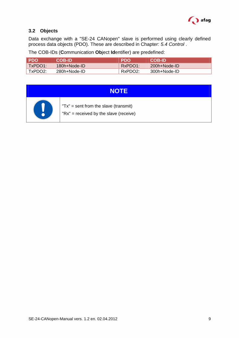
3.2 Objects
Data exchange with a "SE-24 CANopen" slave is performed using clearly defined process data objects (PDO). These are described in Chapter: 5.4 Control .
The COB-IDs (Communication Object Identifier) are predefined:
PDO COB-ID PDO COB-ID
TxPDO1: 180h+Node-ID RxPDO1: 200h+Node-ID
TxPDO2: 280h+Node-ID RxPDO2: 300h+Node-ID
NOTE
"Tx" = sent from the slave (transmit)
"Rx" = received by the slave (receive)

10 SE-24-CANopen-Manual vers. 1.2 en. 02.04.2012
3.3 Documentation about CAN and CANopen
CAN (Controller Area Network) is a standard developed by CiA (CAN in Automation) Hersteller- und Nutzerorganisation e.V. The description of the field bus system can be found in the following standards:
ISO 11898-2 (CAN transmission technology)
EN 50325-4 (CANopen protocol)
Further information, contact addresses etc. can be found at www.can-cia.org.
More detailed documentation for the use of CAN:
1. CAN Specification 2.0, Part A & Part B
2. High Layer Protocol CANopen
3. “CANopen” Holger Zeltwanger VDE Verlag ISBN 3-8007-2448-0
SE-24-CANopen-Manual vers. 1.2 en. 02.04.2012 11
4 Wiring and pin assignment
4.1 Pin assignment
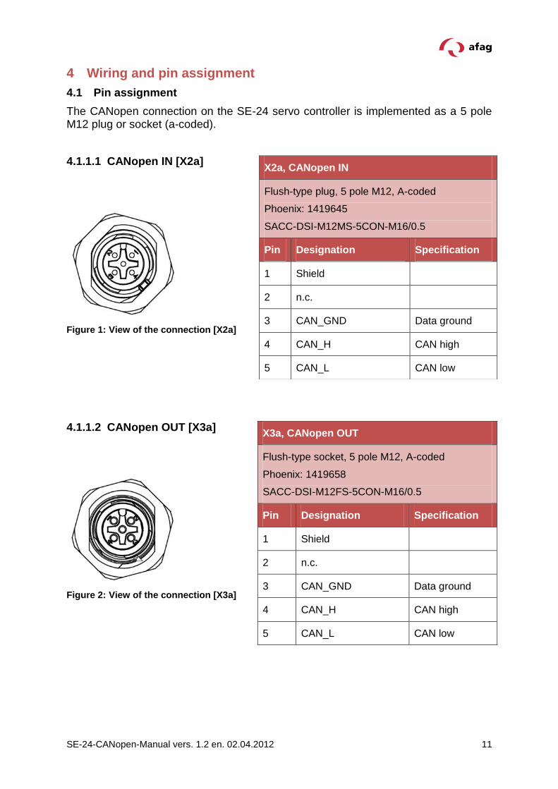
The CANopen connection on the SE-24 servo controller is implemented as a 5 pole M12 plug or socket (a-coded).
4.1.1.1 CANopen IN [X2a]
Figure 1: View of the connection [X2a]
4.1.1.2 CANopen OUT [X3a]
Figure 2: View of the connection [X3a]
X2a, CANopen IN
Flush-type plug, 5 pole M12, A-coded
Phoenix: 1419645
SACC-DSI-M12MS-5CON-M16/0.5
Pin Designation Specification
1 Shield
2 n.c.
3 CAN_GND Data ground
4 CAN_H CAN high
5 CAN_L CAN low
X3a, CANopen OUT
Flush-type socket, 5 pole M12, A-coded
Phoenix: 1419658
SACC-DSI-M12FS-5CON-M16/0.5
Pin Designation Specification
1 Shield
2 n.c.
3 CAN_GND Data ground
4 CAN_H CAN high
5 CAN_L CAN low

12 SE-24-CANopen-Manual vers. 1.2 en. 02.04.2012
NOTE
CAN cabling
When constructing the CAN network, strictly follow the advice of the current literature or the following information and instructions to obtain a stable and fault-free system. In the case of cabling not having been done properly, faults can occur on the CAN during operation which result in the servo controller switching off with an error message for safety reasons.
4.1.2 Bus cable for CANopen
The following cables of the company Phoenix Contact should be used for the CANopen connection:
Bus system cable, CANopen/DeviceNet, 5 pole, PUR halogen-free, violet RAL 4001, shielded, straight M12-SPEEDCON plug, A-coded, on straight M12-SPEEDCON socket, A-coded
Phoenix Contact CANopen cables
CANopen cable Order No. Length in m
1518258 0,3
1518261 0,5
1518274 1
1518287 2
1518290 5
1518300 10
1518313 15
SE-24-CANopen-Manual vers. 1.2 en. 02.04.2012 13
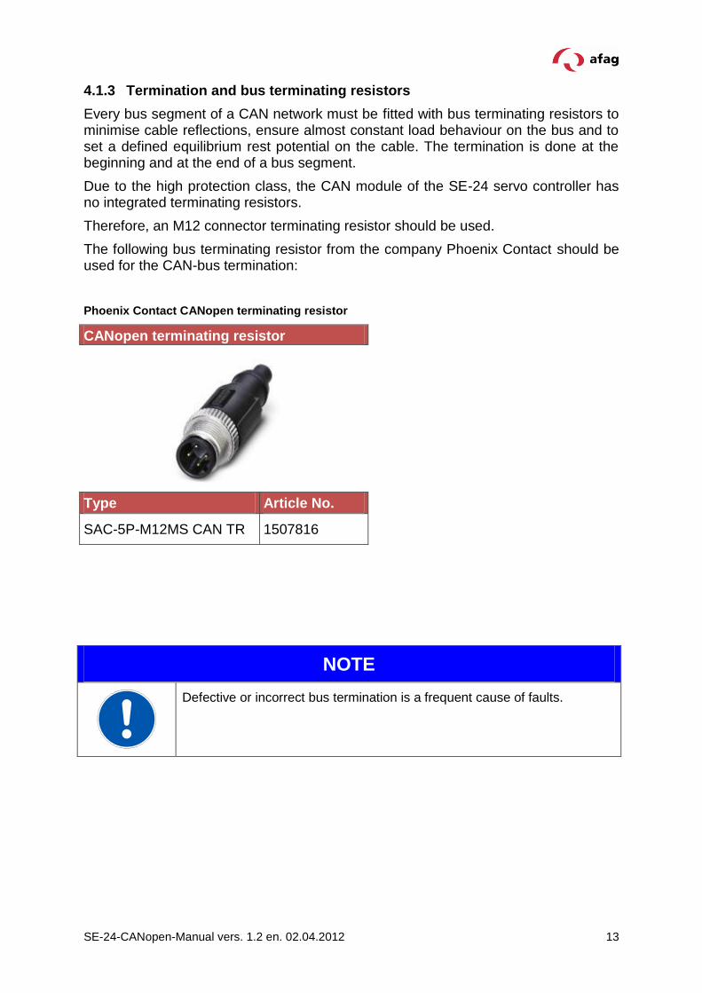
4.1.3 Termination and bus terminating resistors
Every bus segment of a CAN network must be fitted with bus terminating resistors to minimise cable reflections, ensure almost constant load behaviour on the bus and to set a defined equilibrium rest potential on the cable. The termination is done at the beginning and at the end of a bus segment.
Due to the high protection class, the CAN module of the SE-24 servo controller has no integrated terminating resistors.
Therefore, an M12 connector terminating resistor should be used.
The following bus terminating resistor from the company Phoenix Contact should be used for the CAN-bus termination:
Phoenix Contact CANopen terminating resistor
CANopen terminating resistor
Type Article No.
SAC-5P-M12MS CAN TR 1507816
NOTE
Defective or incorrect bus termination is a frequent cause of faults.
14 SE-24-CANopen-Manual vers. 1.2 en. 02.04.2012
5 CAN interface connection
5.1 Introduction
A number of steps are necessary to create a functioning CAN interface connection. Some of these settings should or must be executed before the activation of the CAN communication. This chapter provides an overview of the corresponding steps.
Data are transmitted via so-called PDOs (Process Data Object). The data are assigned fixed (mapped) on the slave (in this case the SE-24). Therefore, on the slave side, only the device address (Node-ID) and the transmission speed (baud rate) and on the master side only how many data items and the arrangement of the data have to be specified.
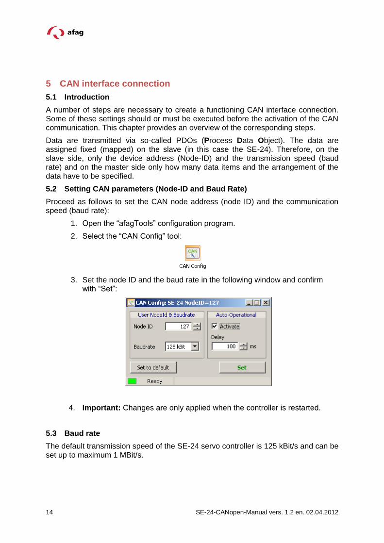
5.2 Setting CAN parameters (Node-ID and Baud Rate)
Proceed as follows to set the CAN node address (node ID) and the communication speed (baud rate):
1. Open the “afagTools” configuration program.
2. Select the “CAN Config” tool:
3. Set the node ID and the baud rate in the following window and confirm with “Set”:
4. Important: Changes are only applied when the controller is restarted.
5.3 Baud rate
The default transmission speed of the SE-24 servo controller is 125 kBit/s and can be set up to maximum 1 MBit/s.

SE-24-CANopen-Manual vers. 1.2 en. 02.04.2012 15
5.4 Control
Two registers are required for operation of the SE-24: the status register which contains the ACTUAL values of the drive, and the control register where the TARGET values are entered.
The signals are described and specified on the following pages.

16 SE-24-CANopen-Manual vers. 1.2 en. 02.04.2012
5.4.1 Status register (actual values)
5.4.1.1 Signal description of the output data of the SE-24 servo controller
Object Description
ready BOOL This signal is set if the drive is ready for operation and can be energised. If there is a fault in the drive, this signal and also the "drive_enable_ok" signal are reset. The "ready" signal will not be set again until the error has been acknowledged by resetting the "drive_enable/fault_res" signal.
drive_enable_ok BOOL Power output stage and control are active.
ref_valid BOOL This signal is set when a valid reference position exists. The signal is not set during an ongoing reference movement. It is set for the first time or once again only after a successfully executed reference movement.
move_ok BOOL This bit is set depending on the traverse mode.
In position mode the signal is set when the actual position is within the position window for a longer time than the set delay time.
In current mode the bit is set when the actual current value is within the current value window for a longer time than the set delay time.
Important:
The signal is reset when the “start_move” signal is set.
This however happens with a certain delay. Therefore it should be noted that the “move_ok” signal must first be queried for LOW and afterwards for HIGH after a run was started with the signal “start_move”.
error_no INT16 Display of the error which has occurred.
position_value
[μm]
[°/1000]
INT32 Actual position
current_value
[mA]
INT32 Actual motor current

SE-24-CANopen-Manual vers. 1.2 en. 02.04.2012 17
5.4.1.2 Output telegram of the SE-24 servo controller
TX PDO 1 (8 bytes)
Status Bits [MPU status register (5101:01)]
0 1 2 3 4 5 6 7 8 9 10 11 12 13 14 15 16 17 18 19 20 21 22 23 24 25 26 27 28 29 30 31
read
y
drive_
en
ab
le_o
k
ref_
va
lid
mo
ve_
ok
error_nr (16-bit)
[Error register (3001:00)]
32 33 34 35 36 37 38 39 40 41 42 43 44 45 46 47 48 49 50 51 52 53 54 55 56 57 58 59 60 61 62 63
position_value (μm, °/1000, 32-bit)
[Actual position (3762:01)]
TX PDO 2 (4 bytes)
0 1 2 3 4 5 6 7 8 9 10 11 12 13 14 15 16 17 18 19 20 21 22 23 24 25 26 27 28 29 30 31
current_value (mA, 32-bit) [Current – actual filtered value
(3262:01)]

18 SE-24-CANopen-Manual vers. 1.2 en. 02.04.2012
5.4.2 Control register (target values)
5.4.2.1 Signal description of the input data of the SE-24 servo controller
Object Description
drive_enable / fault_res BOOL This signal is assigned twice. Controller release = Hi-active / error acknowledgement = Lo-active LOW => motor is not energised, errors are acknowledged. Change 0=>1, if there is no error, the motor will be energised during a change from LOW to HIGH and remains controlled until an error occurs or the signal is set to LOW. If this input is set the first time after a restart, the offset angle of the commutation position is first determined (only for motors without Hall encoder). Change 1=>0, if there is an error, the controller will try to acknowledge the pending errors. This is only possible if the cause for the error has been rectified.
start/stop_ref BOOL A rising edge causes a reference run to be executed. A falling edge aborts the reference run. The sequence is as follows: Setting of the signal “drive_enable/fault_res”, wait until the signal “drive_enable_ok” is at HIGH. Then set the signal “start/stop_ref”, the reference run is executed. Wait until the signal “ref_ok” is at HIGH, the reference run is terminated. The controller is now ready for positioning.
start/stop_move BOOL A rising edge signals that a new movement order should be undertaken and started. In case of a falling edge the SE-24 is stopped quickly. This input has no influence during a reference run. Precondition is however that no error is pending, that controller release is active and a successful reference run was carried out, i.e. the outputs “ready”, “drive_enable_ok” and “ref_valid” must be set.
mode BOOL Operating mode: position / current mode LOW = position controller mode HIGH = current controller mode
pos_nr INT4 Position set (binary) which should be approached. The position sets (1-15) are preconfigured with the “Positioning sets” tool window in the “Manual operation" tool of the “afag Tools” configuration software.
Caution: When the movement is made using the position sets, the values of the "mode", "move_relative", "target_position", "velocity", "deceleration", "acceleration" and "target_current" objects are ignored.

SE-24-CANopen-Manual vers. 1.2 en. 02.04.2012 19
jog_pos
BOOL When the input is set the drive accelerates with the acceleration set for the Jog mode to a pre-parameterized positive movement speed. In case of a falling edge at this input, the drive brakes to a standstill with the deceleration set for the quick-stop. This input has no effect during the reference-, position or current run.
jog_neg BOOL When the input is set the drive accelerates with the acceleration set for the Jog mode to a pre-parameterized negative movement speed. In case of a falling edge at this input, the drive brakes to a standstill with the deceleration set for the quick-stop. This input has no effect during the reference-, position or current run.
move_relativ BOOL Change between absolute and relative. LOW=absolute, HIGH=relative
target_position [μm]
[°/1000]
INT32 Target position The position target value is interpreted as an absolute or relative position depending on the “move_relative” signal.
velocity [mm/s]
[°/s]
INT16 Target movement speed
acceleration [mm/s2]
[°/s2]
INT16 Target acceleration
deceleration [mm/s2]
[°/s2]
INT16 Target deceleration
target_current [%] INT16 Target current value The moment target value is determined by the higher level control system (in % of the positive current limiting). It defines the moment with which the drive should move.

20 SE-24-CANopen-Manual vers. 1.2 en. 02.04.2012
5.4.2.2 Input telegram of the SE-24 servo controller
RX PDO 1 (8 bytes)
Control Bits [MPU control register (5101:02)]
0 1 2 3 4 5 6 7 8 9 10 11 12 13 14 15
drive_
en
ab
le / f
ault_re
s
sta
rt/s
top_
ref
sta
rt/s
top_m
ove
mo
de
pos_
nr_
bit0
pos_
nr_
bit1
pos_
nr_
bit2
pos_
nr_
bit3
jog_
po
s
jog_
ne
g
mo
ve_
rela
tive
16 17 18 19 20 21 22 23 24 25 26 27 28 29 30 31 32 33 34 35 36 37 38 39 40 41 42 43 44 45 46 47
target_position (μm, °/1000, 32-bit) [MPU target position (5102:01)]
48 49 50 51 52 53 54 55 56 57 58 59 60 61 62 63
velocity (mm/s, °/s, 16-bit) [MPU velocity (5102:02)]
RX PDO 2 (6 bytes)
0 1 2 3 4 5 6 7 8 9 10 11 12 13 14 15 16 17 18 19 20 21 22 23 24 25 26 27 28 29 30 31
acceleration (mm/s2, °/s2, 16-bit) [MPU acceleration (5103:02)] deceleration (mm/s2, °/s2, 16-bit) [MPU deceleration (5104:01)]
32 33 34 35 36 37 38 39 40 41 42 43 44 45 46 47
target_current (%, 16-bit) [MPU target current (5103:01)]

SE-24-CANopen-Manual vers. 1.2 en. 02.04.2012 21
5.5 Integration in a PLC
The following EDS file is provided for the integration in a higher level PLC:
SE-24.eds
The assignment of the PDOs to the COB-IDs can be found in Chapter: 3.2 Objects
The description of the PDOs can be found in Chapter: 5.4 Control

22 SE-24-CANopen-Manual vers. 1.2 en. 02.04.2012
6 Signal diagram
ready
drive_enable_ok
rev_valid
move_ok
drive_enable_fault_res
start_stop_rev
start_stop_move
mode
Restart Search start of commut. pos.
Commutation position found Start reference run
End reference run Start in positioning mode
Position window reached Start in current mode
Current window reached Start in positioning mode
Fault Cancel position run Start reference run
Search commut. pos. Position run End reference run Fault Acknowledge fault
Reference run Current run Switch on controller release

SE-24-CANopen-Manual vers. 1.2 en. 02.04.2012 23

Afag Automation AG
Fiechtenstrasse 32
CH - 4950 Huttwil
Switzerland
Tel.: +41 (0)62 959 86 86
Fax: +41 (0)62 959 87 87
e-mail: [email protected]
website: www.afag.com