SERVICE MANUAL METERING/DOSING PUMP - …€¦ · section: metering/dosing pumps page: 1 of 5 date:...
5
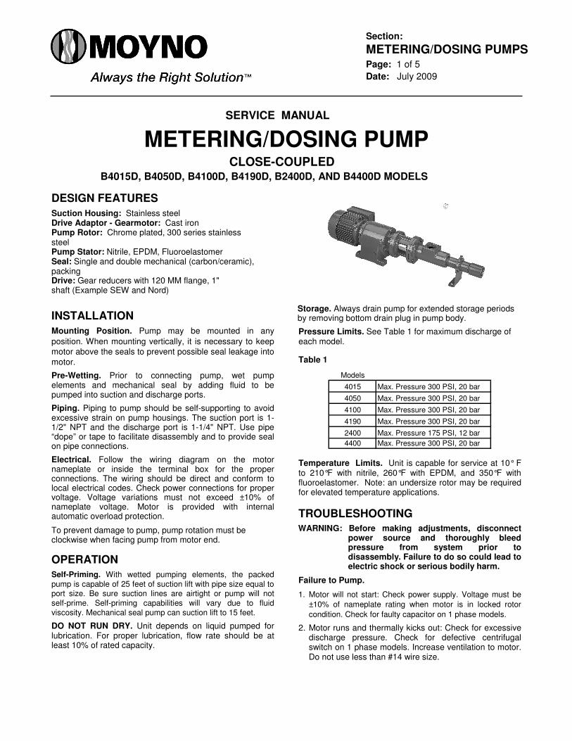
Section: METERING/DOSING PUMPS Page: 1 of 5 Date: July 2009 SERVICE MANUAL METERING/DOSING PUMP CLOSE-COUPLED B4015D, B4050D, B4100D, B4190D, B2400D, AND B4400D MODELS DESIGN FEATURES Suction Housing: Stainless steel Drive Adaptor - Gearmotor: Cast iron Pump Rotor: Chrome plated, 300 series stainless steel Pump Stator: Nitrile, EPDM, Fluoroelastomer Seal: Single and double mechanical (carbon/ceramic), packing Drive: Gear reducers with 120 MM flange, 1" shaft (Example SEW and Nord) INSTALLATION Mounting Position. Pump may be mounted in any position. When mounting vertically, it is necessary to keep motor above the seals to prevent possible seal leakage into motor. Pre-Wetting. Prior to connecting pump, wet pump elements and mechanical seal by adding fluid to be pumped into suction and discharge ports. Piping. Piping to pump should be self-supporting to avoid excessive strain on pump housings. The suction port is 1- 1/2" NPT and the discharge port is 1-1/4" NPT. Use pipe “dope” or tape to facilitate disassembly and to provide seal on pipe connections. Electrical. Follow the wiring diagram on the motor nameplate or inside the terminal box for the proper connections. The wiring should be direct and conform to local electrical codes. Check power connections for proper voltage. Voltage variations must not exceed ±10% of nameplate voltage. Motor is provided with internal automatic overload protection. To prevent damage to pump, pump rotation must be clockwise when facing pump from motor end. OPERATION Self-Priming. With wetted pumping elements, the packed pump is capable of 25 feet of suction lift with pipe size equal to port size. Be sure suction lines are airtight or pump will not self-prime. Self-priming capabilities will vary due to fluid viscosity. Mechanical seal pump can suction lift to 15 feet. DO NOT RUN DRY. Unit depends on liquid pumped for lubrication. For proper lubrication, flow rate should be at least 10% of rated capacity. Storage. Always drain pump for extended storage periods by removing bottom drain plug in pump body. Pressure Limits. See Table 1 for maximum discharge of each model. Table 1 Models 4015 Max. Pressure 300 PSI, 20 bar 4050 Max. Pressure 300 PSI, 20 bar 4100 Max. Pressure 300 PSI, 20 bar 4190 Max. Pressure 300 PSI, 20 bar 2400 Max. Pressure 175 PSI, 12 bar 4400 Max. Pressure 300 PSI, 20 bar Temperature Limits. Unit is capable for service at 10° F to 210°F with nitrile, 260°F with EPDM, and 350°F with fluoroelastomer. Note: an undersize rotor may be required for elevated temperature applications. TROUBLESHOOTING WARNING: Before making adjustments, disconnect power source and thoroughly bleed pressure from system prior to disassembly. Failure to do so could lead to electric shock or serious bodily harm. Failure to Pump. 1. Motor will not start: Check power supply. Voltage must be ±10% of nameplate rating when motor is in locked rotor condition. Check for faulty capacitor on 1 phase models. 2. Motor runs and thermally kicks out: Check for excessive discharge pressure. Check for defective centrifugal switch on 1 phase models. Increase ventilation to motor. Do not use less than #14 wire size.
-
Upload
trannguyet -
Category
Documents
-
view
221 -
download
0
Transcript of SERVICE MANUAL METERING/DOSING PUMP - …€¦ · section: metering/dosing pumps page: 1 of 5 date:...
Section: METERING/DOSING PUMPS Page: 1 of 5 Date: July 2009
SERVICE MANUAL
METERING/DOSING PUMP
CLOSE-COUPLED B4015D, B4050D, B4100D, B4190D, B2400D, AND B4400D MODELS
DESIGN FEATURES Suction Housing: Stainless steel Drive Adaptor - Gearmotor: Cast iron Pump Rotor: Chrome plated, 300 series stainless steel Pump Stator: Nitrile, EPDM, Fluoroelastomer Seal: Single and double mechanical (carbon/ceramic), packing Drive: Gear reducers with 120 MM flange, 1" shaft (Example SEW and Nord) INSTALLATION Mounting Position. Pump may be mounted in any
position. When mounting vertically, it is necessary to keep motor above the seals to prevent possible seal leakage into
motor. Pre-Wetting. Prior to connecting pump, wet pump elements and mechanical seal by adding fluid to be pumped into suction and discharge ports. Piping. Piping to pump should be self-supporting to avoid excessive strain on pump housings. The suction port is 1-1/2" NPT and the discharge port is 1-1/4" NPT. Use pipe “dope” or tape to facilitate disassembly and to provide seal on pipe connections. Electrical. Follow the wiring diagram on the motor nameplate or inside the terminal box for the proper connections. The wiring should be direct and conform to local electrical codes. Check power connections for proper voltage. Voltage variations must not exceed ±10% of nameplate voltage. Motor is provided with internal automatic overload protection. To prevent damage to pump, pump rotation must be clockwise when facing pump from motor end. OPERATION Self-Priming. With wetted pumping elements, the packed pump is capable of 25 feet of suction lift with pipe size equal to port size. Be sure suction lines are airtight or pump will not self-prime. Self-priming capabilities will vary due to fluid viscosity. Mechanical seal pump can suction lift to 15 feet. DO NOT RUN DRY. Unit depends on liquid pumped for lubrication. For proper lubrication, flow rate should be at least 10% of rated capacity.
Storage. Always drain pump for extended storage periods by removing bottom drain plug in pump body. Pressure Limits. See Table 1 for maximum discharge of each model. Table 1
Models
4015 Max. Pressure 300 PSI, 20 bar
4050 Max. Pressure 300 PSI, 20 bar
4100 Max. Pressure 300 PSI, 20 bar
4190 Max. Pressure 300 PSI, 20 bar
2400 Max. Pressure 175 PSI, 12 bar
4400 Max. Pressure 300 PSI, 20 bar Temperature Limits. Unit is capable for service at 10° F to 210°F with nitrile, 260°F with EPDM, and 350°F with fluoroelastomer. Note: an undersize rotor may be required for elevated temperature applications. TROUBLESHOOTING WARNING: Before making adjustments, disconnect
power source and thoroughly bleed pressure from system prior to disassembly. Failure to do so could lead to electric shock or serious bodily harm.
Failure to Pump. 1. Motor will not start: Check power supply. Voltage must be
±10% of nameplate rating when motor is in locked rotor
condition. Check for faulty capacitor on 1 phase models. 2. Motor runs and thermally kicks out: Check for excessive
discharge pressure. Check for defective centrifugal switch on 1 phase models. Increase ventilation to motor. Do not use less than #14 wire size.
Page 2
3. Stator torn; possible excessive pressure: Replace stator,
check pressure at discharge port. 4. Flexible joint broken; possible excessive pressure:
Replace joint, check pressure at discharge port. 5. Wrong rotation (3 phase only): Rotation must be
clockwise when facing pump from motor end. Reverse the connections of any two line leads to the motor.
Pump Overloads. 1. Excessive discharge pressure. Check pressure at
discharge port for maximum ratings given in Table 1. 2. Fluid viscosity too high: Limit fluid viscosity per “How to
Select” calculations. Noisy Operation. 1. Excessive suction lift or vacuum: Maximum suction lift is
25 feet for water. 2. Suction line too small: Check pipe size. Be sure lines are
free from obstructions. 3. Pump Cavitates: At pump speed of 1725 rpm. Viscosity
of fluid should not exceed 100 CP or 500 SSU. 4. Flexible joint worn: Replace joint. Check pressure at
discharge port. 5. Insufficient mounting: Mount to a firm base. Vibration
induced noise can be reduced by using mount pads and short sections of hose on suction and discharge ports.
Seal Leakage. 1. Leakage at startup: If leakage is slight, allow pump to
run several hours to let faces run in. 2. Persistent seal leakage: Faces may be cracked from
freezing or thermal shock. Replace seal. Pump Will Not Prime. 1. Air leak on suction side: Check pipe connections. PUMP DISASSEMBLY WARNING: Before disassembling pump, disconnect
power source and thoroughly bleed pressure from system. Failure to do so could result in electric shock or serious bodily harm.
1. Remove suction and discharge piping. Drain pump body by removing drain plug (261).
2. Remove discharge coupling (9) from stator (21). 3. Remove stator support clamp (40). 4. Remove stator (21) by unthreading from the suction
housing (2). Lock rotor from turning by inserting a punch into the hole located in the center of the flexible joint (24). This will aid in removing the stator.
5. Remove the stator support retainer (39) if desired. 6. Remove the suction housing (2) by removing the screws
(112) and lock washers (215). 7. Remove O-Ring (270) from the seal housing (3) (71) or
the stuffing box (4). Inspect and replace if necessary.
8. Remove the rotor & shaft pins (46) from the flexible joint (24). Support the joint/rotor while removing with a small punch. These pins should not be reused. Replace with new pins upon reassembly.
9. Clean and inspect the flexible joint (24) looking for excessive play and breaks in the rubber boots. If sealing boots are damaged replace the flexible joint.
10. If packed model skip to Step 14.
Single Seal. Remove the mechanical seal (69) spring
and spring retainer from the drive shaft assembly (26).
Double Seal. Remove seal housing (71) and O-ring
(72), inspect, replace if necessary. 11. Remove the rotational portion of the mechanical seal
from the drive shaft (26). 12. Remove the seal housing (3) or seal gland (73) from
the drive adapter casting (1). 13. Remove the mechanical seal stationary from the seal
housing (3) (71) and seal gland (73). Replace seal components if worn. Go to Step 16.
14. Remove the stuffing box (4) from the drive adapter
casting (1). 15. Remove the packing gland halves (65) from the studs
and remove the worn packing (72). 16. Remove the set screws (27) from the drive shaft
assembly (26). 17. Remove the drive shaft assembly (26) from the
motor/gearmotor shaft. 18. Remove the drive adapter casting from the motor/
gearmotor. This completes the pump disassembly. PUMP ASSEMBLY 1. Mount the drive adapter casting (1) to the
motor/gearmotor, using appropriate hardware with the windows horizontal.
2. Slide the drive shaft assembly (26) onto the motor/ gearmotor shaft, seating firmly against the shaft end.
3. Install the set screws (27) into the drife shaft assembly (26) locking the drive shaft assembly to the motor/gearmotor shaft.
4. On packed pump skip to Step 5.
Install the mechanical seal (69) (70) using the following procedure:
a. Clean and oil sealing faces using clean oil (not grease). CAUTION: Do not use oil on EPDM parts. Substitute
glycerin or soap and water. b. Oil outer surfaces of the seal seat, and push seat
assembly into the seal housing (3) and seal gland on double seals.
c. Slide the seal housing (3) or seal gland (73) onto the
drive shaft assembly (26) seating into the drive adapter (1).
d. After cleaning and oiling the shaft, slide the seal body
along the drive shaft assembly (26) until it meets the seal seat.
e. Install the seal spring and spring retainer or second
seal body on the shaft.
f. On double seal models, insert seal stationary into seal housing (71), mount O-ring (72) and slide onto shaft, enclosing the double seal.
Page 3 5. On packed pumps perform the following:
a. Insert the packing rings (72) into the stuffing box alternating the joints 90˚.
b. Install the packing gland halves (65) on the studs
(70) without tightening on the packing.
11. Slide stator (21) onto rotor (22) using hand soap or
equivalent as lubrication. Thread stator into suction housing (2) using pipe “dope” or sealing tape to ensure a leak-proof seal. To keep the rotor from turning, insert a punch into the hole in the flexible joint.
12. Slide stator support retainer ring (39) onto the stator. c. Slide the stuffing box assembly onto the drive shaft
assembly (26). Set the studs horizontal, seating the 13. Use the stator support clamp (40) to connect the stator stuffing box into the drive adapter casting.
6. Insert the flexible joint (24) into the drive shaft assembly (26). Insert shaft pin (46) into the hole using a small punch. The seal spring will move to allow clearance for insertion. The spring retainer should rest against the flexible joint (24) after pin insertion.
7. Support flexible joint and insert rotor (22) aligning holes for insertion of rotor pin (46) using a small punch.
8. Insert O-Ring (270) into the groove in the seal housing
(3) or stuffing box (4). 9. Install the drain plug (261) into suction housing (2) using
pipe “dope” or sealing tape to ensure a leak-proof seal. 10. Attach the suction housing (2) to the drive adapter
casting, using screws (112) and lockwashers (215). Note, a gap will remain between the suction housing and drive adapter casting.
support (38). 14. Thread discharge coupling (9) onto the stator (21) using
pipe “dope” or sealing tape to ensure a leak-proof seal. 15. Lubricate rotor and stator by filling the suction housing
with fluid to be pumped. 16. Firmly mount the pump. Connect suction and discharge
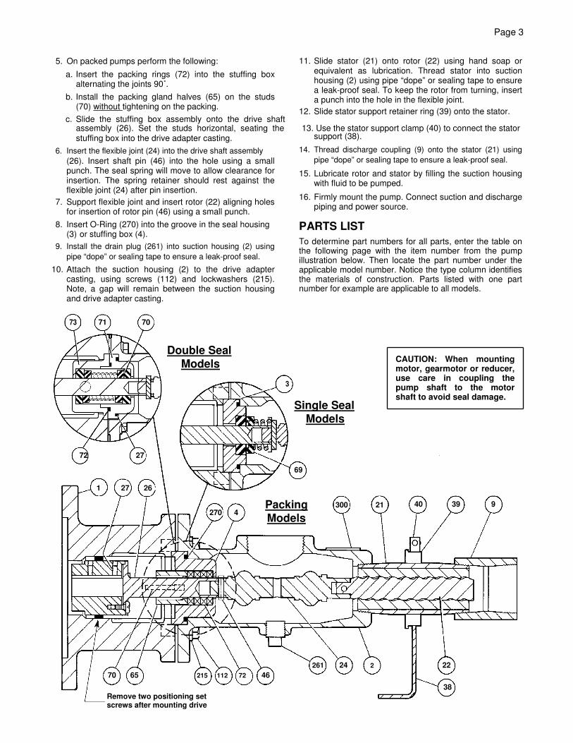
piping and power source. PARTS LIST To determine part numbers for all parts, enter the table on the following page with the item number from the pump illustration below. Then locate the part number under the applicable model number. Notice the type column identifies the materials of construction. Parts listed with one part number for example are applicable to all models.
733 71 700
Double Seal
Models
3
Single Seal
3
Models
72 270
69
1 27 266
3000 21
Packing
2700 44
Models
CAUTION: When mounting motor, gearmotor or reducer, use care in coupling the pump shaft to the motor shaft to avoid seal damage.
40 39 9
261 24 2 22 70 65 215 112 72 46
38 Remove two positioning set screws after mounting drive

Page 4
CLOSE COUPLED MODELS PARTS LIST
1 CD Drive Adapter - Gearmotor 1
2 SS Suction Housing 1
3 SS Seal Housing 1
4 SS Stuffing Box 1
9 SS Discharge Coupling 1
21 See Table Stator 1
22 See Table Rotor 1
24 Q,R,B,F Flexible Joint 1
26 SS Drive Shaft Assembly 127 SS Set Screw 2
38 SS Stator Support 1
39 SS Stator Support Retainer 140 SS Clamp Assembly 146 SS Rotor/Shaft Pin 2
65 SS Packing Gland Half 2
69 Q,R,B,F Mech Seal (Cbn vs Cer) 1
69 Q,R,B,F Mech Seal (AR) 1
70 Q,R,B,F Double Mechanical Seal 1
71 SS Seal Housing, Double 1
72 SS Packing Set 172 Q,R,B,F O-Ring 1
73 SS Seal Gland, Double 1
111 SS Packing Gland Stud 2
112 SS Screw 4
215 SS Lock Washer 4
261 SS Drain Plug 1
270 Q,R O-Ring 1
270 B O-Ring 1
270 F O-Ring 1300 SS Name Plate 1
Item Type Description Qty B4015, B4050, B4100, B4190, B2400, B4400
3206503000
3501688003
3403932007
3403930007
3403934007
See Stator Table
See Rotor Table
6060340040
3403945001
3208597000
6191520141
6230010401
6100420030
3207905134
3207904134
3205342020
3207902134
32017330003204277000 and 3201734000
3403986015
34033960023207902128
3204069001
3403933007
3308811005
3208591000
3403943003
3206501000
3208652002
3403985015
Element Q (Nitirle) B (EPDM) F (Fluoro)
4015 3403923104 3403923304 3403923504
4050 3202145013 3203676013 3303719013
4100 3403924104 3403925304 3403924504
4190 3403925104 3403925304 3240392504
2400 4252489102 4252489302 4252489502
4400 4252489104 4252489304 4252489504
Stator Material
Element300 Series
Stainless Steel
4015 3403927015
4050 4252492015
4100 3403928015
4190 3403929015
2400 42525240154400 4252491015
Rotor
Page 5
For further information, call:
Inside U.S.A. - 800-845-1310 or 800-325-1331 Outside U.S.A. - 937-327-3553
© 2009 by Moyno, Inc. ® Moyno is a registered trademark of Moyno, Inc. Moyno, Inc. is part of the Fluid Management Group of Robbins & Myers, Inc. Printed in U.S.A.