
Service and Repair Manual - Helac Corporation | … and Repair Manual HELICAL HYDRAULIC ROTARY...
32
L30 SERIES Service and Repair Manual HELICAL HYDRAULIC ROTARY ACTUATORS
Transcript of Service and Repair Manual - Helac Corporation | … and Repair Manual HELICAL HYDRAULIC ROTARY...

L30 SERIESService andRepair Manual
HELIC
AL H
YD
RA
ULIC
RO
TAR
Y A
CTU
ATOR
S
2
Table of Contents
Introduction
Table of Contents .................................................................................................................................. 2
Product Introduction .............................................................................................................................. 3
General Safety Guidelines .................................................................................................................... 4
Product Identification ............................................................................................................................ 4
Theory of Operation .............................................................................................................................. 5
Tools
Tools Required ...................................................................................................................................... 6
Spare Parts - Tech Support .................................................................................................................. 7
Drawings
Assembly Drawing ................................................................................................................................ 8
Exploded View ...................................................................................................................................... 9
Spare Parts .........................................................................................................................................10
Parts List .............................................................................................................................................10
Valve Block Exploded View .................................................................................................................11
Valve Block Parts List .........................................................................................................................11
Disassembly
Before Disassembly .............................................................................................................................12
Disassembly .......................................................................................................................................12
Inspection ............................................................................................................................................18
Assembly
Seal and Wear Guide Installation .........................................................................................................18
Assembly ............................................................................................................................................22
Post Assembly
Greasing Thrust Washers ....................................................................................................................25
Testing the Actuator ............................................................................................................................25
Installation and Bleeding ......................................................................................................................26
Troubleshooting Guide .........................................................................................................................27
Warranty Information ............................................................................................................................28
About Helac .........................................................................................................................................32

3
Product Introduction
For over 30 years, Helac Corporation has beenrecognized for innovation in design of hydraulicrotary actuators and construction equipmentattachments. Helac products are known for theirtremendous torque output, compact configurations,exceptional load bearing capabilities, and rugged,reliable performance. Over 1,000 mobile, industrial,construction and mining machinery manufacturersaround the world depend on Helac actuators toperform such functions as rotation, positioning,manipulation, vehicle steering and indexing.
The L30 Series is available in several different sizes.All L30 Series actuators incorporate the sameinternal design, though they vary in size dependingon model.

4
General Safety Guidelines
Each Helac actuator is individually serial numbered.The serial number is a six digit number and must beprovided before parts and/or service issues can beaddressed.The serial number can be found on the Identification(ID) Tag that is affixed to all actuators. The tag is a thin,silver colored, plastic label with a self-adhesivebacking. Information is imprinted in black. The tag islocated on the housing tube of the actuator. In somecases, the ID tag may be painted over by the OEM(Original Equipment Manufacturer).
Additionally, the serial number of the actuator isstamped onto the housing tube. It may be necessary toremove paint to expose the serial number.
Product Identification
StampedSerial
Number
Identification(ID) Tag
Many L30 actuator applications have several pinchpoints with the potential for severe injuries. Use ex-treme caution and remain clear of all rotating compo-nents when bleeding the hydraulic system and when-ever the machine is in operation.
After rebuilding or repairing an actuator, it is necessaryto bleed all air from the actuator as well as the hydraulicsystem of the machine.

5
Theory of Operation
The L30 Series rotary actuator is a simplemechanism that uses Helac's sliding splinetechnology which converts linear piston motion intopowerful shaft rotation. Each actuator is composed ofa housing with an integral ring gear (1) and only twomoving parts: the central shaft (2) with an integratedbearing and mounting flange, and the annular pistonsleeve (3).
Helical spline teeth machined on the shaft engagematching splines on the inside diameter of the piston.The outside diameter of the piston carries a secondset of splines, of opposite hand, which engage thematching splines of the housing's ring gear.
As hydraulic pressure is applied, the piston isdisplaced axially within the housing - similar to theoperation of a hydraulic cylinder - whilesimultaneously, the splines cause the shaft to rotate.When the control valve is closed, oil is trapped insidethe housing, preventing piston movement and locking
the shaft firmly in position.
The shaft is supported radially by the large upper radialbearing and the lower radial bearing (see drawings onpages 8 and 9). Axially, the shaft is separated from thehousing by the upper and lower thrust washers. Theend cap is adjusted for axial clearance and locked inposition by set screws, pins or locking collar.
The L30 Series is available in several different sizes .All L30 Series actuators incorporate the same internaldesign, though they vary in size depending on model.
Many actuators are equipped with a factory installedcounterbalance valve, which performs four majorfunctions.
• Protects the actuator in the event of overload
• Enables the actuator to hold position without driftingwhen external loads are applied
• Reduces hydraulic backlash by pressuring thehydraulic fluid
• Provides a constant controlled rate of rotation inover-center load conditions
Bars indicate starting positions ofpiston and shaft. Arrows indicatedirection they will rotate. Thehousing with integral ring gearremains stationary. For clarity,the shaft flange, bearings, andend cap are not shown.
Applying fluid pressure willdisplace the piston axially whilethe helical gearing causes thepiston and shaft to rotatesimultaneously. The double helixdesign compounds rotation:shaft rotation is about twice thatof the piston. Applying pressureto the opposite port will returnthe piston and shaft to theiroriginal starting positions.
3
2
1
6
Tools Required
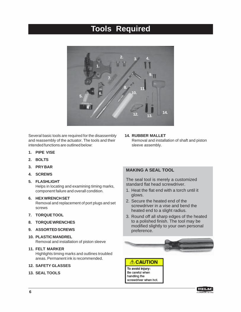
Several basic tools are required for the disassemblyand reassembly of the actuator. The tools and theirintended functions are outlined below:
1. PIPE VISE
2. BOLTS
3. PRY BAR
4. SCREWS
5. FLASHLIGHTHelps in locating and examining timing marks,component failure and overall condition.
6. HEX WRENCH SETRemoval and replacement of port plugs and setscrews
7. TORQUE TOOL
8. TORQUE WRENCHES
9. ASSORTED SCREWS
10. PLASTIC MANDRELRemoval and installation of piston sleeve
11. FELT MARKERHighlights timing marks and outlines troubledareas. Permanent ink is recommended.
12. SAFETY GLASSES
13. SEAL TOOLS
14. RUBBER MALLETRemoval and installation of shaft and pistonsleeve assembly.
1.
2. 3. 4.
5.6.
7.
8.
14.13.12.
10.
9.
MAKING A SEAL TOOL
The seal tool is merely a customizedstandard flat head screwdriver.1. Heat the flat end with a torch until it
glows.2. Secure the heated end of the
screwdriver in a vise and bend theheated end to a slight radius.
3. Round off all sharp edges of the heatedto a polished finish. The tool may bemodified slightly to your own personalpreference.
11.

7
Spare parts must be ordered through thevehicle/machine OEM. Seals and bearings areavailable as complete kits only! In order toobtain the correct parts, it is essential toprovide the serial number of the actuator to be
repaired, see Product Identification section onpage 4. To identify spare parts required, referto the Assembly Drawing on page 9 and PartsList on page 10.
Spare Parts
Technical support is available from Helac Corporation, Monday through Friday 7 am to 4 pmPacific Standard Time by calling 800-327-2589. If possible, please have the serial number of theactuator available. (The serial number is stamped into the housing of the actuator-see page 4).
Technical Support

8
Assembly Drawing
L30 Assembly Drawing

9
Exploded View
L30 Exploded View

10
PARTS
Item Description Quantity
1 ........... Housing ......................................................... 12 ........... Shaft .............................................................. 13 ........... Piston Sleeve Assembly ............................... 14 ........... End Cap ........................................................ 15 ........... Lock Nut ........................................................ 1
HARDWARE
Item Description Quantity
100 ....... Dowel, Pin .................................................... 2105 ....... Fitting, Plug SAE-4 ....................................... 4106 ....... Fitting, Port Plug SAE-6 ................................ 2109 ....... Pull-Out Dowel, Pin ...................................... 2111 ....... Fitting, Grease, 1/8 NPT ................................ 2112 ....... Fitting, Grease Relief, 1/8 NPT ..................... 2
SEALS
Item Description Quantity
200 ....... Cup Seal ...................................................... 2201 ....... Cup Seal (energizer ring removed) ............. 1202 ....... Cup Seal ...................................................... 1203 ....... Cup Seal (energizer ring removed) ............. 1205 ....... Main Pressure - Z-Seal ................................ 2206 ....... Exclusion Seal ............................................. 2208 ....... O-Ring - Seal ................................................ 1209 ....... O-Ring - Seal ................................................ 1
WEAR GUIDES
Item Description Quantity
300 ....... Wear Guide ................................................... 2301 ....... Wear Guide ................................................... 1302 ....... Wear Guide ................................................... 2304 ....... Thrust Washer .............................................. 2
OPTIONAL ACCESSORIES
Item Description Quantity
400 ....... Stop Tube (O-Ring included)(not shown) ... 1401 ....... Counterbalance Valve .................................. 1406 ....... Hydraulic Tubing Assembly ......................... 1
Parts List
Spare PartsSpare parts must be ordered through the vehicle/machine OEM. Seals and wear guides are available as completekits only! In order to obtain the correct parts, it is essential to provide the serial number for the actuator to berepaired. See Product Identification on Page 4. To identify spare parts required, refer to the Assembly Drawing,Exploded View Drawing and the Parts List.
11
Valve Block Exploded View
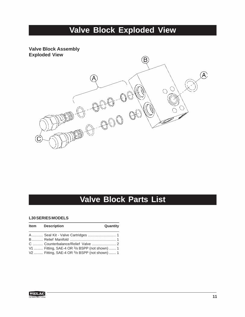
Valve Block AssemblyExploded View
L30 SERIES MODELS
Item Description Quantity
A ........... Seal Kit - Valve Cartridges ............................ 1B ........... Relief Manifold .............................................. 1C .......... Counterbalance/Relief Valve ........................ 2V1 ......... Fitting, SAE-4 OR 3/8 BSPP (not shown) ....... 1V2 ......... Fitting, SAE-4 OR 3/8 BSPP (not shown) ....... 1
Valve Block Parts List
12
Disassembly
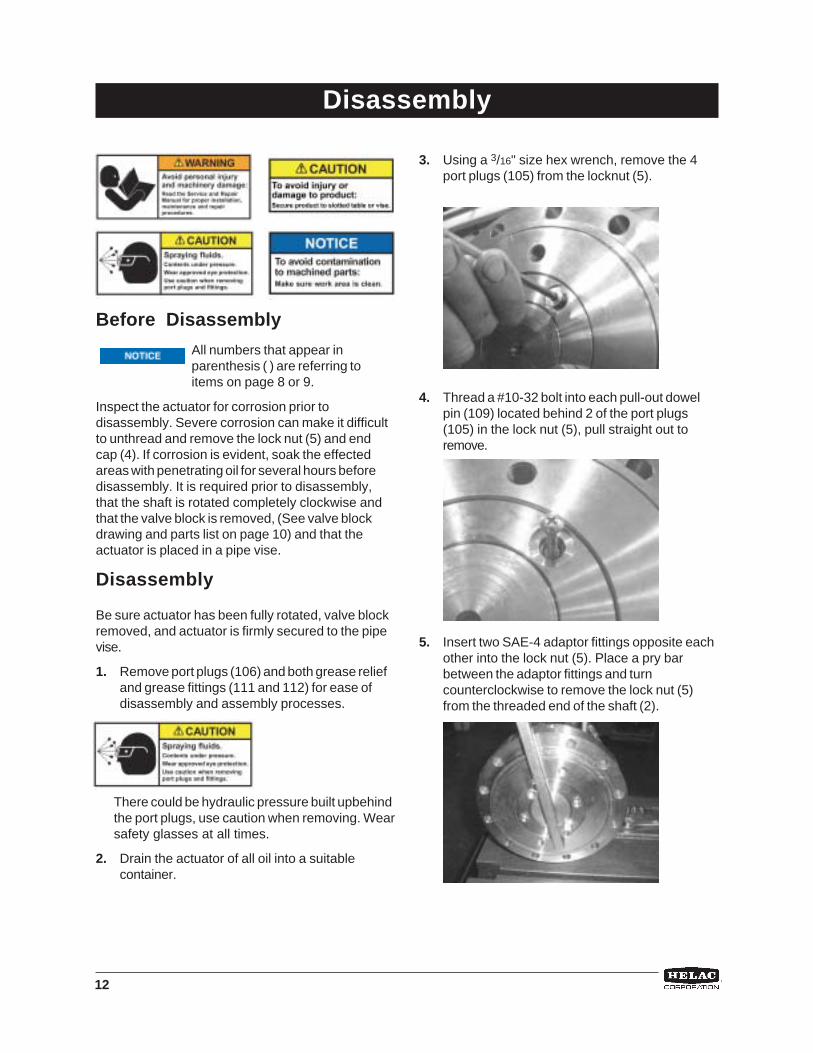
Before Disassembly
All numbers that appear inparenthesis ( ) are referring toitems on page 8 or 9.
Inspect the actuator for corrosion prior todisassembly. Severe corrosion can make it difficultto unthread and remove the lock nut (5) and endcap (4). If corrosion is evident, soak the effectedareas with penetrating oil for several hours beforedisassembly. It is required prior to disassembly,that the shaft is rotated completely clockwise andthat the valve block is removed, (See valve blockdrawing and parts list on page 10) and that theactuator is placed in a pipe vise.
Disassembly
Be sure actuator has been fully rotated, valve blockremoved, and actuator is firmly secured to the pipevise.
1. Remove port plugs (106) and both grease reliefand grease fittings (111 and 112) for ease ofdisassembly and assembly processes.
There could be hydraulic pressure built upbehindthe port plugs, use caution when removing. Wearsafety glasses at all times.
2. Drain the actuator of all oil into a suitablecontainer.
3. Using a 3/16" size hex wrench, remove the 4port plugs (105) from the locknut (5).
4. Thread a #10-32 bolt into each pull-out dowelpin (109) located behind 2 of the port plugs(105) in the lock nut (5), pull straight out toremove.
5. Insert two SAE-4 adaptor fittings opposite eachother into the lock nut (5). Place a pry barbetween the adaptor fittings and turncounterclockwise to remove the lock nut (5)from the threaded end of the shaft (2).

13
6. Insert two 5/8"-11 threaded bolts opposite eachother into the end cap (4). Pull straight out toremove end cap (4). See Photo Below
If needed, to break the seal friction,the end cap can be removed byfirst removing the shaft (see step 7)then tapping the inside of the endcap through the actuator housingand piston sleeve with a rubbermallet and plastic mandrel. Do notlet end cap fall.
7. Thread two M16x2 threaded bolts into the shaft(2) flange. Using a long pry bar turn the shaft (2)counterclockwise. It will start to rotate out ofthe housing. If it does not rotate out of thehousing, use a plastic mandrel to tap thethreaded end to break the hydraulic lock andstart the shaft out of the housing. (Do notrotate shaft out of gear engagement withthe piston). Look on the gear end of the pistonsleeve (3) and locate the existing timing marks(center punches), make new timing marks ifneeded. Take a felt pen and clearly mark thegear engagement at the timing marks on boththe piston and shaft. Upon reassembly thesame gear engagement (timing) has to beachieved. Rotate the shaft out of the actuator.Support the weight of the shaft to preventdamage to the rod surface. See Photos toRight.
Disassembly
Piston Gearto Shafttiming mark
Shaft gear toPiston timingmarks
Piston Gearto Housingtiming mark
Shaft Gearto Pistontiming marks
14
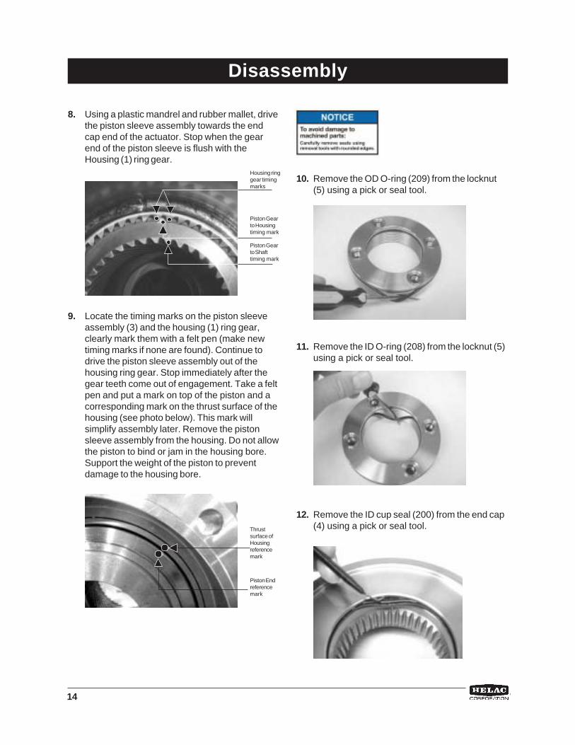
8. Using a plastic mandrel and rubber mallet, drivethe piston sleeve assembly towards the endcap end of the actuator. Stop when the gearend of the piston sleeve is flush with theHousing (1) ring gear.
9. Locate the timing marks on the piston sleeveassembly (3) and the housing (1) ring gear,clearly mark them with a felt pen (make newtiming marks if none are found). Continue todrive the piston sleeve assembly out of thehousing ring gear. Stop immediately after thegear teeth come out of engagement. Take a feltpen and put a mark on top of the piston and acorresponding mark on the thrust surface of thehousing (see photo below). This mark willsimplify assembly later. Remove the pistonsleeve assembly from the housing. Do not allowthe piston to bind or jam in the housing bore.Support the weight of the piston to preventdamage to the housing bore.
10. Remove the OD O-ring (209) from the locknut(5) using a pick or seal tool.
11. Remove the ID O-ring (208) from the locknut (5)using a pick or seal tool.
12. Remove the ID cup seal (200) from the end cap(4) using a pick or seal tool.
Housing ringgear timingmarks
Piston Gearto Housingtiming mark
Piston Gearto Shafttiming mark
Piston Endreferencemark
Thrustsurface ofHousingreferencemark
Disassembly

15
13. Remove the wear guide (302) from the end cap(4).
14. Remove the main pressure seal (205) from theend cap (4) using a seal tool.
15. Remove the thrust washer (304) from the endcap (4).
Disassembly
16. Remove the exclusion seal (206) from the endcap (4) using a seal tool.
17. Remove the ID cup seal (200) from the pistonsleeve assembly (3) using a seal tool.
18. Remove the ID wear guide (301) from the pistonsleeve assembly (3) using a pick tool.
16
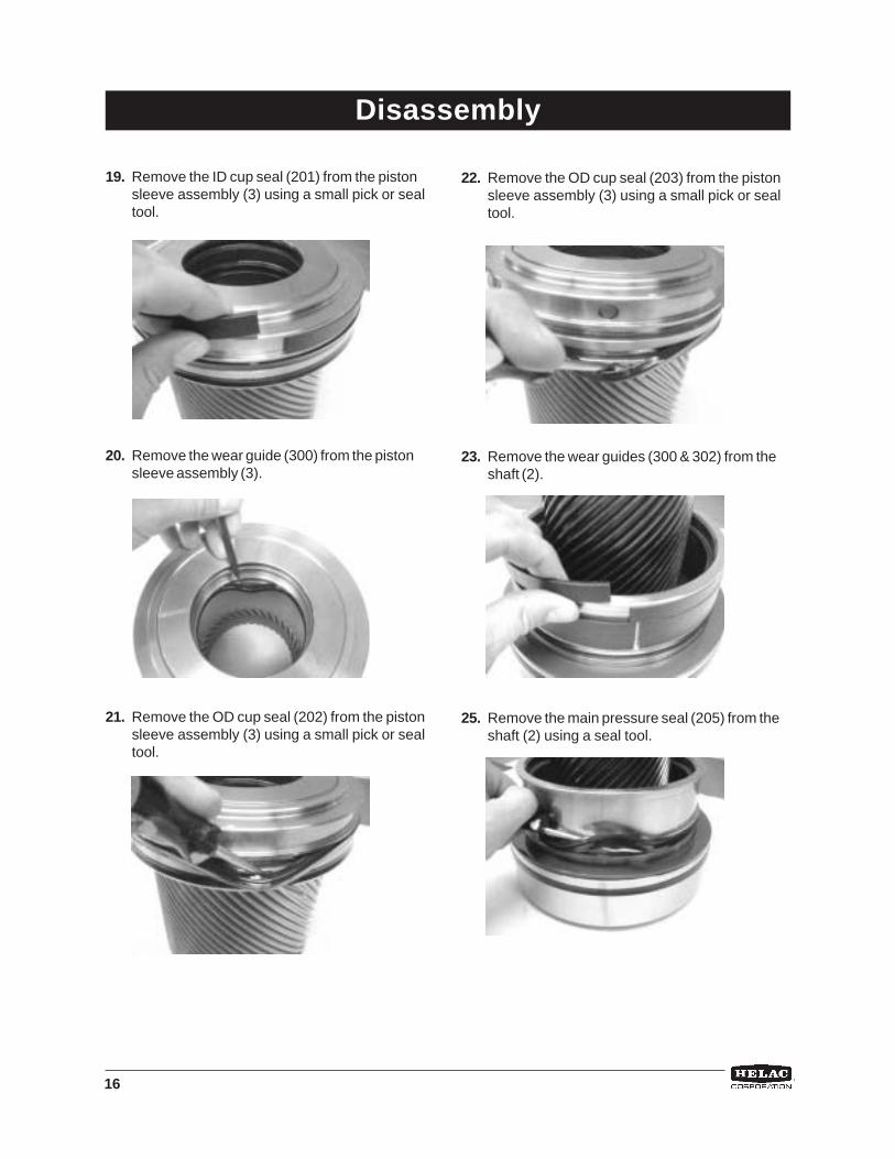
22. Remove the OD cup seal (203) from the pistonsleeve assembly (3) using a small pick or sealtool.
23. Remove the wear guides (300 & 302) from theshaft (2).
25. Remove the main pressure seal (205) from theshaft (2) using a seal tool.
19. Remove the ID cup seal (201) from the pistonsleeve assembly (3) using a small pick or sealtool.
20. Remove the wear guide (300) from the pistonsleeve assembly (3).
21. Remove the OD cup seal (202) from the pistonsleeve assembly (3) using a small pick or sealtool.
Disassembly
17
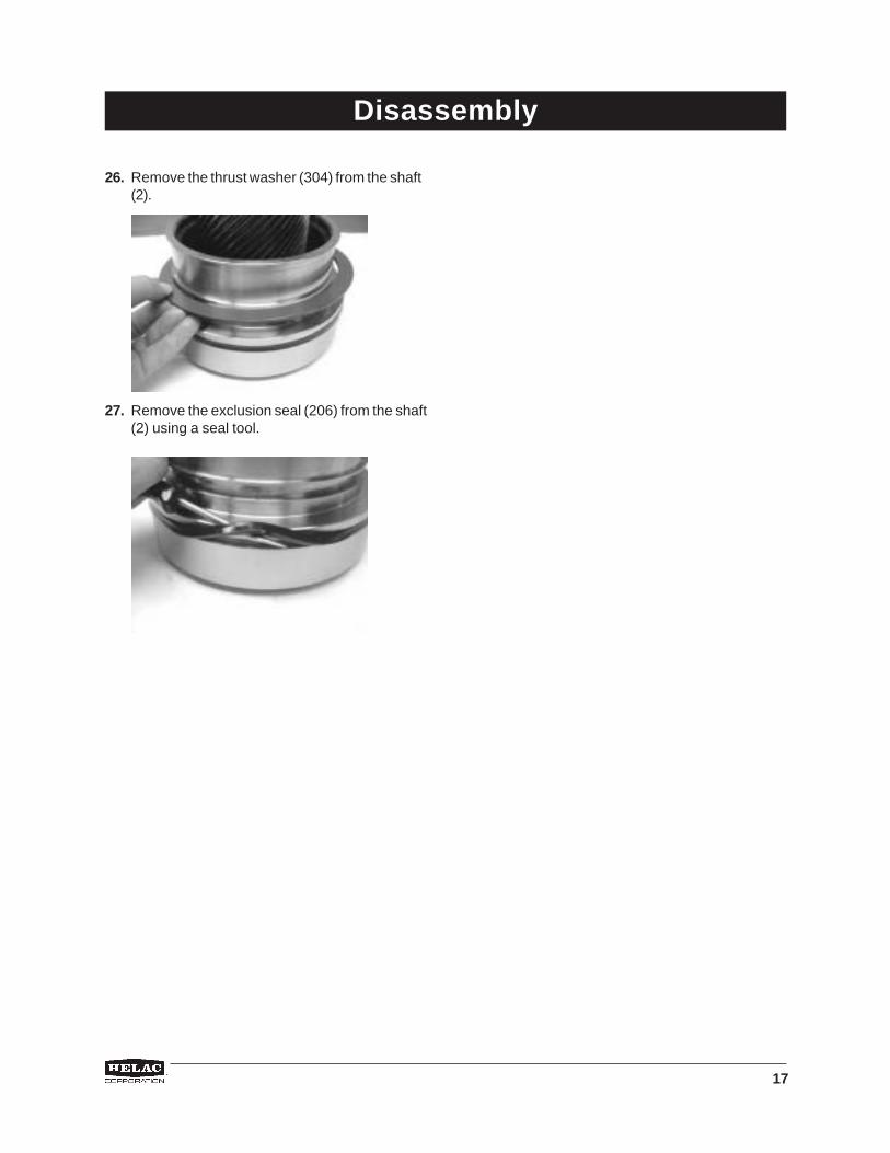
26. Remove the thrust washer (304) from the shaft(2).
27. Remove the exclusion seal (206) from the shaft(2) using a seal tool.
Disassembly
18
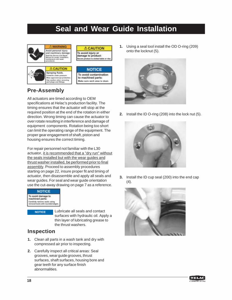
1. Using a seal tool install the OD O-ring (209)onto the locknut (5).
2. Install the ID O-ring (208) into the lock nut (5).
3. Install the ID cup seal (200) into the end cap(4).
Pre-AssemblyAll actuators are timed according to OEMspecifications at Helac's production facility. Thetiming ensures that the actuator will stop at therequired position at the end of the rotation in eitherdirection. Wrong timing can cause the actuator toover rotate resulting in interference and damage ofequipment components. Rotation being too shortcan limit the operating range of the equipment. Theproper gear engagement of shaft, piston andhousing ensures the correct timing.
For repair personnel not familiar with the L30actuator, it is recommended that a "dry run" withoutthe seals installed but with the wear guides andthrust washer installed, be performed prior to finalassembly. Proceed to assembly proceduresstarting on page 22, insure proper fit and timing ofactuator, then disassemble and apply all seals andwear guides. For seal and wear guide orientationuse the cut-away drawing on page 7 as a reference.
Lubricate all seals and contactsurfaces with hydraulic oil. Apply athin layer of lubricating grease tothe thrust washers.
Seal and Wear Guide Installation
Inspection1. Clean all parts in a wash tank and dry with
compressed air prior to inspecting.
2. Carefully inspect all critical areas: Sealgrooves, wear guide grooves, thrustsurfaces, shaft surfaces, housing bore andgear teeth for any surface finishabnormalities.

19
4. Install the exclusion seal (206) onto the endcap (4) using a seal tool.
5. Lightly grease both sides of the thrust washerwith Lithium grease(304) and install onto theend cap (4).
6. Install the main pressure seal (205) onto theend cap (4) using a seal tool.
7. Install the wear guide (302) onto the end cap(4).
8. Install the OD cup seal (203) with the energizerring removed, onto the piston sleeve assembly(3) using a seal tool.
9. Install the OD cup seal (202) onto the pistonsleeve assembly (3) using a seal tool.
Seal and Wear Guide Installation
* NOTE: Several models use O.D. T-sealthat comes without an energizer ring.Install the O.D. seal and two backup rings.
20
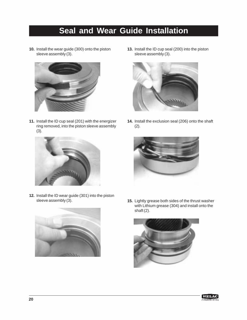
10. Install the wear guide (300) onto the pistonsleeve assembly (3).
11. Install the ID cup seal (201) with the energizerring removed, into the piston sleeve assembly(3).
12. Install the ID wear guide (301) into the pistonsleeve assembly (3).
13. Install the ID cup seal (200) into the pistonsleeve assembly (3).
14. Install the exclusion seal (206) onto the shaft(2).
15. Lightly grease both sides of the thrust washerwith Lithium grease (304) and install onto theshaft (2).
Seal and Wear Guide Installation

21
16. Install the main pressure seal (205) onto theshaft (2).
17. Install wear guides (300&302) onto the shaft (2).
Seal and Wear Guide Installation

22
Assembly1. Secure the actuator to a pipe vise, then
carefully slide the piston sleeve assembly (3),gear teeth first, into the end cap end of theactuator. (Be careful not to bind or jam thepiston sleeve assembly in the housing).Stop when the end of the piston is flush withthe thrust surface of the housing (1) and the tworeference marks, made during disassembly lineup.( The gear teeth of the piston sleeveassembly should be almost ready to engagethe housing (1) ring gear teeth).
2. Confirm proper gear alignment from the shaftflange end, then use a rubber mallet and plasticmandrel to engage the piston sleeve assemblygear teeth and housing ring gear teeth. Drivepiston in until the front of the piston sleeve islined up with the housing ring gear (see photobelow). Locate the timing marks on the pistonsleeve gear teeth and the housing ring gearteeth. Both timing marks should be lined up. Ifnot, disengage the piston from the ring gear andline up with the correct gear engagement.
3. Using a rubber mallet and plastic mandrel,continue to drive piston sleeve assembly (3)towards the shaft flange end of actuator untilthe piston sleeve assembly is fully seatedagainst the housing ring gear.
Housing ringgear timingmarks
Piston Gearto Housingtiming mark
Piston Gearto Shafttiming mark
Piston Endreferencemark
Thrustsurface ofHousingreferencemark
Assembly

23
4. Install the shaft (2) threaded end first into thepiston sleeve assembly (3). The shaft (2) gearteeth timing mark and the piston sleeveassembly (3) gear teeth timing mark must belined up.
5. Install two M16x2 bolts into the shaft (2) flange.Using a long pry bar turn the shaft (2)clockwise. Be sure both timing marks on thegear teeth are lined up. Rotate shaft (2) in untilapproximately 2 inches are still between theshaft flange and the housing.
6. Grease the end cap (4) splines with Lithiumgrease. Install two 5/8"-11 bolts in the end capand slide end cap into the housing. Carefullytap the end cap (4) with a rubber mallet until theseals enter the housing and the end capbecomes flush with the housing.
7. Using the pry bar turn the shaft (2) clockwiseslowly to engage the shaft (2) splines and theend cap (4) splines. If needed, use the twobolts on the end cap to turn end cap for properalignment of the splines. After engagement ofsplines, fully seat the shaft (2) clockwise intothe housing.
Assembly
Piston Gearto Shafttiming mark
Shaft gear toPiston timingmarks
Piston Gearto Housingtiming mark
24
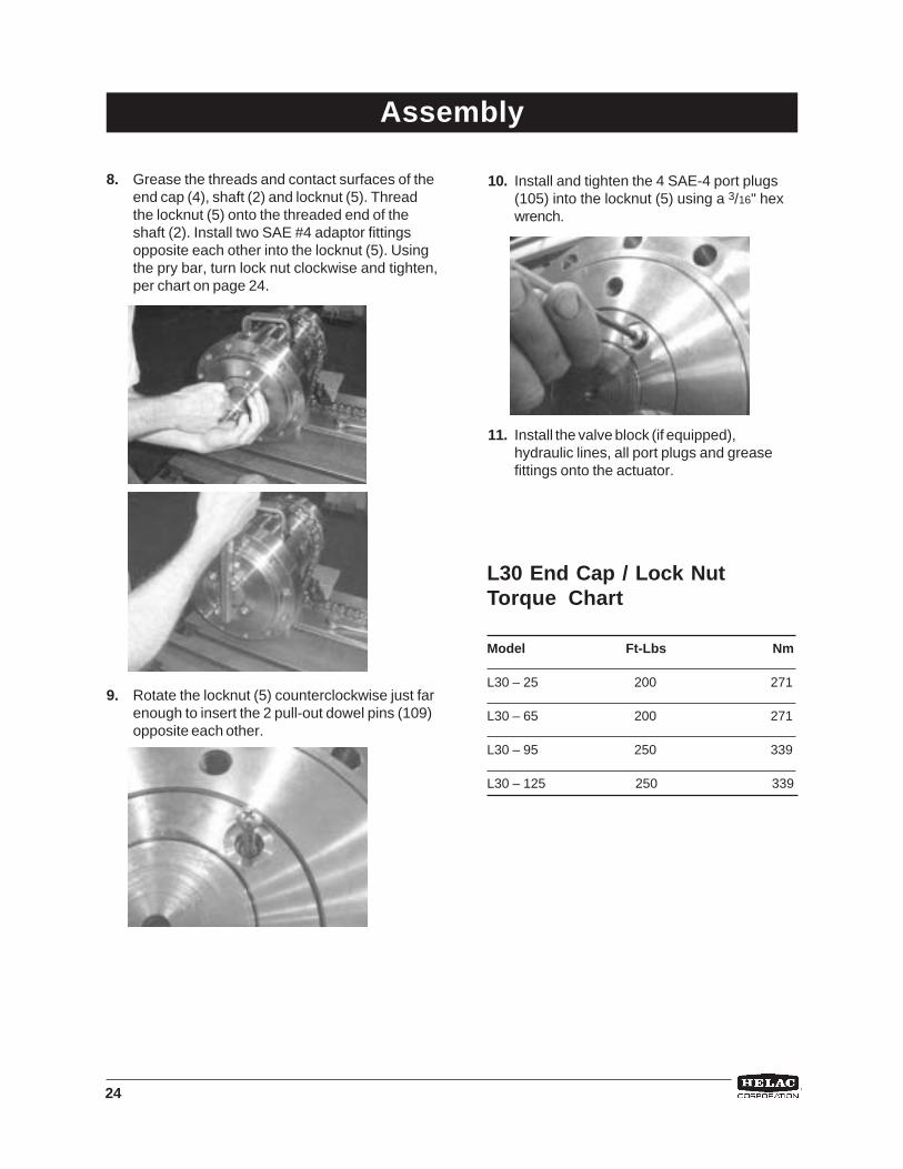
8. Grease the threads and contact surfaces of theend cap (4), shaft (2) and locknut (5). Threadthe locknut (5) onto the threaded end of theshaft (2). Install two SAE #4 adaptor fittingsopposite each other into the locknut (5). Usingthe pry bar, turn lock nut clockwise and tighten,per chart on page 24.
9. Rotate the locknut (5) counterclockwise just farenough to insert the 2 pull-out dowel pins (109)opposite each other.
Assembly
L30 End Cap / Lock NutTorque Chart
Model Ft-Lbs Nm
L30 – 25 200 271
L30 – 65 200 271
L30 – 95 250 339
L30 – 125 250 339
10. Install and tighten the 4 SAE-4 port plugs(105) into the locknut (5) using a 3/16" hexwrench.
11. Install the valve block (if equipped),hydraulic lines, all port plugs and greasefittings onto the actuator.
25
After the actuator is assembled but before it is putback into service, the thrust washers and exclusionseals must be packed with Lithium grease.
1. There are two male grease fittings (111) andtwo grease relief ports (112), one of each(111,112) is located at both ends of the outerdiameter of the housing (1). (See exploded viewon page 8 for reference).
If a hydraulic test bench is notavailable, the actuator can berotated by hand, open the pressureports and use a pry bar with capscrews inserted into the shaftflange to turn the shaft in thedesired direction.
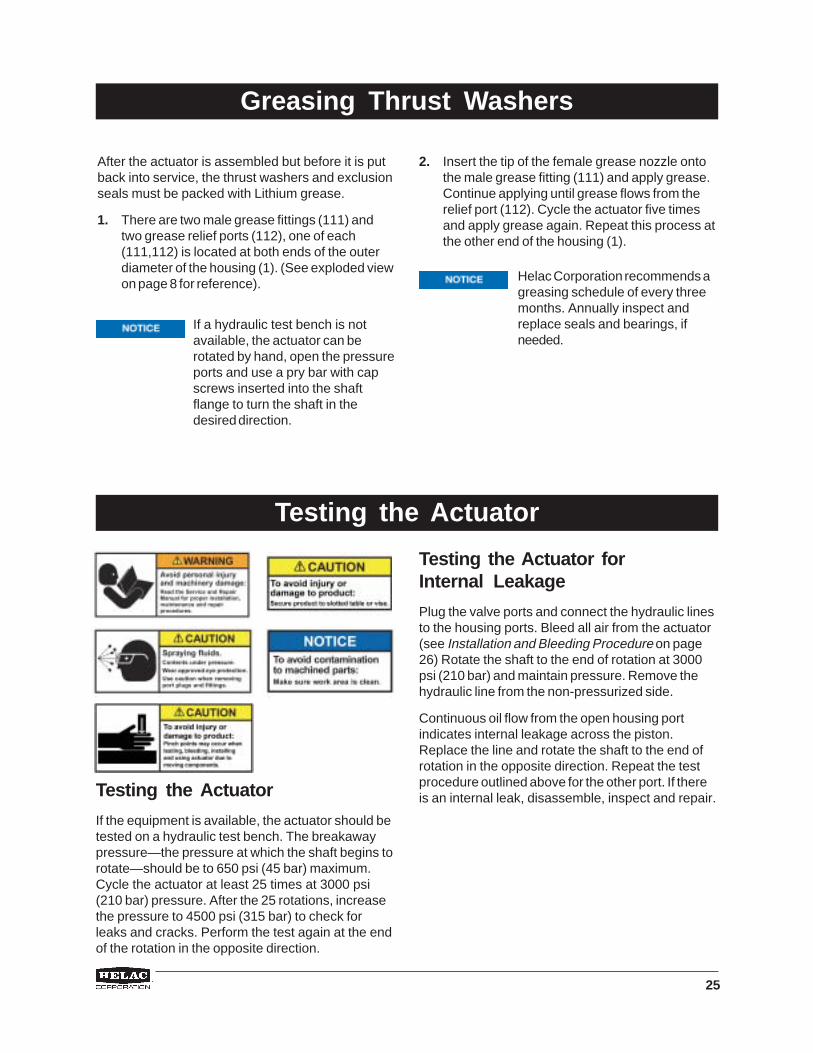
Testing the Actuator
If the equipment is available, the actuator should betested on a hydraulic test bench. The breakawaypressure—the pressure at which the shaft begins torotate—should be to 650 psi (45 bar) maximum.Cycle the actuator at least 25 times at 3000 psi(210 bar) pressure. After the 25 rotations, increasethe pressure to 4500 psi (315 bar) to check forleaks and cracks. Perform the test again at the endof the rotation in the opposite direction.
Greasing Thrust Washers
2. Insert the tip of the female grease nozzle ontothe male grease fitting (111) and apply grease.Continue applying until grease flows from therelief port (112). Cycle the actuator five timesand apply grease again. Repeat this process atthe other end of the housing (1).
Testing the Actuator
Testing the Actuator forInternal Leakage
Plug the valve ports and connect the hydraulic linesto the housing ports. Bleed all air from the actuator(see Installation and Bleeding Procedure on page26) Rotate the shaft to the end of rotation at 3000psi (210 bar) and maintain pressure. Remove thehydraulic line from the non-pressurized side.
Continuous oil flow from the open housing portindicates internal leakage across the piston.Replace the line and rotate the shaft to the end ofrotation in the opposite direction. Repeat the testprocedure outlined above for the other port. If thereis an internal leak, disassemble, inspect and repair.
Helac Corporation recommends agreasing schedule of every threemonths. Annually inspect andreplace seals and bearings, ifneeded.

26
Installation and BleedingAfter installation of the actuator onto the equipment,it is important that all safety devices such as tierods or safety cables be properly reattached. Theactuator body is equipped with a pair of port plugs(106) which can be removed for bleeding.
For actuators with an optional valve blockinstalled.
1. Connect the pressure lines to ports V1 and V2.
2. Connect a hydraulic line to port P1 routed eitherback to tank or to a 5 gallon container to collectthe purged oil.
3. Apply pressure to port V2 until actuator hasfully rotated to one side.
4. With port P1 still open, apply pressure to theprimary port V1 allowing oil/air to be purgedfrom the open port.
5. Install port P1 plug and attach purge line to portP2.
6. Apply pressure to port V1 until actuator hasfully rotated in the opposite direction.
7. With port P2 still open, apply pressure to portV2 allowing oil/air to be purged from the openport.
8. Install port P2 plug.
9. All air should be purged from the actuator.
For actuator without optional valve blockinstalled.
Air should be purged through the upper ports P1and P2. With that in mind, apply pressure hoses tothe lower ports P1 and P2.
1. Connect a hydraulic line to upper port P1 routedeither back to tank or to a 5 gallon container tocollect the purged oil.
2. Apply pressure to lower port P2 until actuatorhas fully rotated to one side.
3. With upper port P1 still open, apply pressure tothe lower port P1 allowing oil/air to be purgedfrom the open port.
4. Install upper port P1 plug and attach purge lineto upper port P2.
5. Apply pressure to lower port P1 until actuatorhas fully rotated to the opposite side.
6. With upper port P2 still open, apply pressure tothe lower port P2 allowing oil/air to be purgedfrom the open port.
7. Install upper port P2 plug.
8. All air should be purged from the actuator.
P1 Port(Shaft End)
P2 Port(End CapEnd)
(106)
V1Port
V2Port
Installation and Bleeding
27
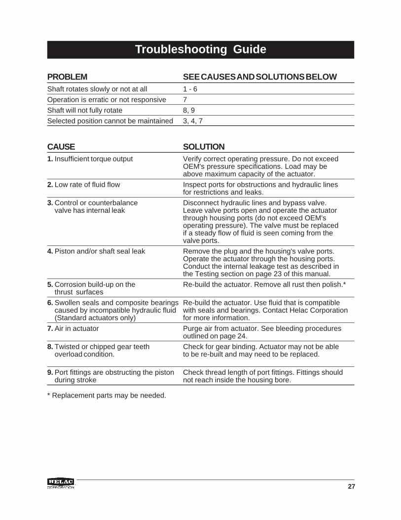
PROBLEM SEE CAUSES AND SOLUTIONS BELOWShaft rotates slowly or not at all 1 - 6
Operation is erratic or not responsive 7
Shaft will not fully rotate 8, 9
Selected position cannot be maintained 3, 4, 7
CAUSE SOLUTION1. Insufficient torque output Verify correct operating pressure. Do not exceed
OEM's pressure specifications. Load may beabove maximum capacity of the actuator.
2. Low rate of fluid flow Inspect ports for obstructions and hydraulic linesfor restrictions and leaks.
3. Control or counterbalance Disconnect hydraulic lines and bypass valve.valve has internal leak Leave valve ports open and operate the actuator
through housing ports (do not exceed OEM'soperating pressure). The valve must be replacedif a steady flow of fluid is seen coming from thevalve ports.
4. Piston and/or shaft seal leak Remove the plug and the housing's valve ports.Operate the actuator through the housing ports.Conduct the internal leakage test as described inthe Testing section on page 23 of this manual.
5. Corrosion build-up on the Re-build the actuator. Remove all rust then polish.*thrust surfaces
6. Swollen seals and composite bearings Re-build the actuator. Use fluid that is compatiblecaused by incompatible hydraulic fluid with seals and bearings. Contact Helac Corporation(Standard actuators only) for more information.
7. Air in actuator Purge air from actuator. See bleeding proceduresoutlined on page 24.
8. Twisted or chipped gear teeth Check for gear binding. Actuator may not be ableoverload condition. to be re-built and may need to be replaced.
9. Port fittings are obstructing the piston Check thread length of port fittings. Fittings shouldduring stroke not reach inside the housing bore.
Troubleshooting Guide
* Replacement parts may be needed.

28
Hydraulic Rotary Actuator Product Warranty
Standard Warranty InformationHelac Corporation warrants its manufactured products to be free from defective material and factory workmanship.Helac Corporation shall replace or repair such products, which under normal use and service disclose suchdefects, and return the repaired or replacement products to the purchaser prepaid. Claims under this warranty willbe satisfied only by repair or replacement of the unit or any defective part thereof. No cash payment or credit will bemade for defective materials, workmanship, labor or incidental charges. Products under warranty shall be returnedto Helac Corporation’s manufacturing facility at 225 Battersby Avenue, Enumclaw, Washington 98022 USA,transportation prepaid by the purchaser, for inspection by Helac Corporation, whose opinion as to defects shall beconclusive.
The warranty period shall be 12 months from the date of shipment from Helac Corporation’s manufacturing facilityfor Helac Corporation approved applications. This warranty shall be voided as to any products which have beenrepaired, worked upon, or altered by persons not authorized by Helac Corporation, or which have been subject tomisuse, negligence, accident, or overload. In no event shall Helac Corporation be liable for any incidental orconsequential damages.
Helac Corporation reserves the right to make changes in the design or construction of any of its products at anytime without incurring any obligations to make changes or alterations to products previously sold.
This warranty is in lieu of all other and/or prior warranties, expressed or implied, and no other company or personis authorized to represent or assume for Helac Corporation any liability in connection with the sale of HelacCorporation products other than set forth herein.
Return and Debit Policy for ActuatorsUnless agreed to in advance, all actuators will be shipped to Helac Corporation, freight prepaid within seven daysafter receipt of return authorization. Prior to any returns, a Return Material Authorization (RMA) form is to berequested from an authorized Helac Corporation representative. Upon receipt of the RMA form, the customer is toprovide when applicable, the part number, serial number, failure date, description of problem and the customerclaim or reference number. All shipments to Helac Corporation are to include the completed RMA form.
Upon receipt of the actuator(s) at the Helac Corporation facilities, an inspection will be performed and anauthorized representative will provide a written quote. This quote will list the findings of the inspection and will statewhether or not the warranty claim has been accepted. Actuators returned for credit may be subject to the HelacCorporation re-stocking fee.
If Helac Corporation does not receive a response to their quote within 30 calendar days, the actuator will be eitherscrapped or returned and an invoice for the debit amount, including the freight charges, will be sent to the claimoriginator.
Return and Debit Policy for Service PartsReturn of service parts, normally stocked by Helac Corporation, must be authorized in advance. This will includeseal and bearing kits as well as any and all fabricated parts. Return of any special order parts will be authorized ona case-by-case basis. All returns are to be shipped to Helac Corporation freight prepaid within seven days afterreceipt of return authorization. Helac Corporation has a minimum re-stocking fee of 20 percent.
Prior to any returns, Return Material Authorization (RMA) form is to be requested from an authorized HelacCorporation representative. Upon receipt of the RMA form, the customer is to providert number, receipt date,description of problem and the customer claim number. All shipments to Helac Corporation are to include thecompleted RMA form.

29
Notes

30
Notes

31
Notes

HELAC CORPORATION225 BATTERSBY AVENUE • ENUMCLAW, WA 98022 USAPHONE 360.825.1601 • FAX 360.825.1603 • www.helac.com
®
Rev
02-
2005
About Helac Corporation
As a leader in the fluid power industry for over30 years, Helac Corporation manufactures acomprehensive line of hydraulic rotaryactuators used as component parts for OEMsand aftermarket attachments for theconstruction equipment industry. Helac rotaryactuators are best known for their tremendoustorque output, compact dimensions,
exceptional load bearing capability and rugged,reliable performance. Helac PowerTilt andPowerGrip, two specialty products, increasethe utilization of backhoes and excavators.Over 1,000 worldwide customers in diversemarkets depend on Helac's product line toprovide product quality, reliability, ease of useand durability.