Serpentine Manipulator Planning and Control for NASA Space
34
Serpentine Manipulator Planning and Control for NASA Space-Shuttle Payload Servicing by Herman Herman Hagen Schempf CMU-RI-TR-92-10 The Robotics Institute Carnegie Mellon University 5000 Forbes Avenue Pittsburgh, PA 15213 October 1992 1992 Carnegie Mellon University
Transcript of Serpentine Manipulator Planning and Control for NASA Space

Serpentine Manipulator Planning and Control for NASA Space-Shuttle
Payload Servicing
by
Herman Herman
Hagen Schempf
CMU-RI-TR-92-10
The Robotics Institute
Carnegie Mellon University
5000 Forbes Avenue
Pittsburgh, PA 15213
October 1992
1992 Carnegie Mellon University

Serpentine Manipulator Planning and Control for NASA Space-Shuttle Payload Servicing
1
Abstract 3
Applications Background 4Payload Changeout Room (PCR)- Facility Configuration and Attributes 4
Technical Background 13
Approach 15
Generating the initial path 17
Snakes 20
Manipulator behavior 22Extension and retraction of the manipulator 22
Fitting the manipulator using iterative scheme 22
The obstacle potential field 25
Operation of the system 26Teleoperation 26Automatic operation 26Scanning 26
References 27
Table of Contents
1. Abstract .......................................................................................................................................4
2. Applications Background ...........................................................................................................52.1 Payload Changeout Room (PCR)- Facility Configuration and Attributes .........................52.2 Serpentine Manipulator for Payload Servicing ...................................................................6
3. Technical Background ..............................................................................................................153.1 Introduction .......................................................................................................................153.2 Approach ...........................................................................................................................163.3 Generating the initial path .................................................................................................183.4 Snakes ...............................................................................................................................203.5 Manipulator behavior ........................................................................................................22
3.5.1 Extension and retraction of the manipulator ............................................................223.5.2 Fitting the manipulator onto the snake ....................................................................22
3.5.2.1 Fitting the manipulator directly to the snake ..................................................233.5.2.2 Fitting the manipulator to the snake with an iterative scheme .......................23
3.6 The obstacle potential field ...............................................................................................253.7 Operation of the system ....................................................................................................26
3.7.1 Teleoperation ...........................................................................................................263.7.2 Automatic Operation ................................................................................................273.7.3 Scanning ...................................................................................................................27
3.8 Conclusion ........................................................................................................................323.9 Acknowledgement ............................................................................................................32
4. References .................................................................................................................................33

Serpentine Manipulator Planning and Control for NASA Space-Shuttle Payload Servicing
2
List of Figures
. The workspace of the space shuttle servicing robot 7
Two ways of moving to a new goal 12
. Choosing path to a new goal 13
The kinematic model for 2 DOF manipulator 16
List of Figures
Figure 2.1: : Space-Shuttle launchpad facility at John F. Kennedy Space Center, Cape Canaveral, Florida 8
Figure 2.2: : Detailed View of Rotating Service Structure (RSS) and the Payload Changeout Room (PCR) 9
Figure 2.3: : Space-Shuttle launchpad showing the Space Shuttle, the Rotating Ser-vice Structure, the Payload Changeout Room, and a payload being hoisted. 10
Figure 2.4: : Birds’-eye-view inside the PCR, showing a payload being maneuvered into the cargo-bay of the space-shuttle mated to the PCR doors. 11
Figure 2.5: : Structure of the platforms and the PGHM inside the PCR, used to access and transport payloads, respectively 12
Figure 2.6: : Elevated View of the platform and PGHM systems 13
Figure 2.7: :Detailed views of inside PCR structures and reaches 14Figure 3.1: : The workspace of the space shuttle servicing robot .................................................15
Figure 3.2: : Two ways of moving to a new goal 19
Figure 3.3: : Choosing path to a new goal 20
Figure 3.4: : Kinematic Model for a 2 DOF serial manipulator 23
Figure 3.5: : The manipulator is entering the workspace by following the computed path to the goal. 28
Figure 3.6: : The manipulator has reached its first goal. 29
Figure 3.7: : The manipulator is retracted in preparation to reach the second goal. 30
Figure 3.8: : The manipulator reaches the second goal. 31

Serpentine Manipulator Planning and Control for NASA Space-Shuttle Payload Servicing
3
List of Tables

Serpentine Manipulator Planning and Control for NASA Space-Shuttle Payload Servicing
4
1. Abstract
The use of a highly-redundant manipulator, so-called ‘serpentine’ manipulator, is proposed as asolution for servicing space-payloads during the payload installation process before launch on thespace-shuttle. The staging of the system would be inside a large cleanroom area, the PayloadChangeout Room (PCR), which sits on the Rotating Service Structure (RSS), allowing it to beswung into mated contact with the space-shuttle as it sits on the launchpad at the John F. KennedySpace Center in Cape Canaveral, Florida (see figures in section 2).
This report is not so much concerned with the design and implementation issues associated with aserpentine manipulator, but rather with the planning, control and user-interface issues. We thuspresent a brief introduction to the actual application environment and its restrictions, followed bythe theoretical background and implementation issues of planning and control algorithmsdeveloped specifically for a serpentine manipulator operating within the confined spaces of thePCR and the space-shuttle cargo-bay.
The approach used to generate a continuous path is to develop and use a minimizing continuousenergy curve for the manipulator, and then fit the discretized link-sections to that curve. Theoperator is then able to modify this curve directly, allowing for shaping of the serpentine, and forthe placement of obstacles that can then be avoided. This algorithm can be implemented inreal-time, and curve-parameters can also be adjusted such as flexibility and curvature of thecurve. An A* method is used to search for the shortest distance between two goal points, in orderto construct the curve. In order to avoid obstacles (real and artificial), available from a database orwhich can be placed by the operator using the operator interface display, we use an obstaclepotential field FIRAS function.
This report outlines the NASA applications background and the technical research andimplementation issues of the different planning and control algorithms. The entire system wassimulated on an SGI IRIS, and a video-tape has been made of the different operational modes ofthe planning and operator control displays, showcasing the different capabilities of the serpentinemanipulator motion planning and control system.

Serpentine Manipulator Planning and Control for NASA Space-Shuttle Payload Servicing
5
2. Applications Background
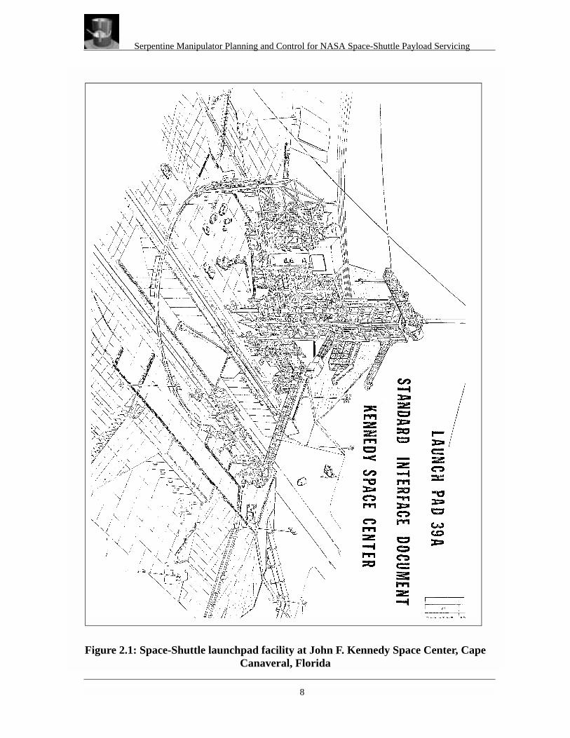
The application of a highly dexterous serpentine manipulator for NASA servicing tasks, wasdeemed most beneficial in servicing space-payloads during the installation of the payloads intothe space-shuttle orbiter [7], while it is on the launch pad at Cape Canaveral Air Force Station atKennedy Space Center in Florida. A drawing of the launch-pad facility is shown in Figure 2.1.The launchpad is used as the location where most payloads are loaded into the space-shuttle rightbefore take-off (see Figure 2.3). The payload installation and checkout all occur within thePayload Changeout Room (PCR), which is mounted on the Rotating Service Structure (RSS),which is used to mate and demate the PCR to/from the shuttle (see Figure 2.1). The descriptionand purpose of the PCR are explained in more detail below.
2.1 Payload Changeout Room (PCR)- Facility Configuration and Attributes
The PCR is used to service payloads while they are at the launch pad. It is part of the RotatingService Structure (RSS) [8], the main movable part of the launch pad. The PCR is used to servicepayloads which will be installed vertically into the orbiter at the pad. The PCR is defined as aclass 100,000 clean room, and its high efficiency particle accumulator (HEPA) filters provide aclass 100,000, non-laminar flow air supply. The temperature is maintained at 70 deg F, withrelative humidity at 50% maximum.
The vertical payloads are transported to thc pad in the vertical position in payload canisters on thepayload transporter. The canister is positioned under the RSS while the RSS is in the retractedposition. The payload canister is lifted from the transporter to the PCR doors and is unlocked inposition. The PCR environmental seals are inflated and the area between the PCR and the orbiteris purged. The PCR-to-orbiter /canister seal system encloses the orbiter payload bay or payloadcanister doors into the PCR interior without exposing the payload bay, the canister interior, or thepayload to contamination by outside elements. The structurally mounted seals are positioned toprovide sealing between the PCR doors and the payload canister or the orbiter. Aluminumstrongbacks provide support for the inflatable seals around the orbiter interface surface. Abird’s-eye view from the top of the PCR room, with shuttle mated to the PCR, doors open, and apayload being positioned inside the cargo bay, is shown in Figure 2.4.

Serpentine Manipulator Planning and Control for NASA Space-Shuttle Payload Servicing
6
The doors to the PCR open allowing access to the outside of the canister doors which are openedinto the PCR. The Payload Ground Handling Mechanism (PGHM) in the PCR is extended andattached to the payload trunnions and the entire payload is withdrawn from the canister into thePCR. First the doors to the canister, then the PCR doors, are closed and the canister andtransporter are removed from the RSS area (see Figure 2.5).
After the orbiter has been positioned on the launch pad, the RSS is rotated to mate the PCR withthe orbiter. First the PCR doors, then the orbiter bay doors are opened and the PGHM is used totransfer the payload form the PRC into the orbiter. As a contingency, the PGHM can also be usedto remove payloads from the orbiter (see Figure 2.5).
Payload access via the present extendable platform system (see Figure 2.7) is currently adequateto facilitate known processing operations, but to reach certain payload unique configurations andenvelopes and/or access to payload areas between platform levels, the use of special supplementalground support equipment (GSE) is required. Payload processing in the Payload ChangeoutRoom (PCR) often requires tasks which are very difficult for humans to perform from theperspective of reasonable accessibility. Payloads in the shuttle bay create long, narrow corridorswhere processing tasks are required. In some cases the payload has to be removed to allow accessfor these tasks. The current handling mechanism and platform systems (see Figure 2.5) do notprovide flexible access to all payloads and critical shuttle bay locations. Thus human techniciansmust assume hazardous positions on specialized fixtures, scaffolds and lifting devices. Thesealternatives all increase cost, possibly increase payload exposure to potential damage, reduceefficiency, flexibility and overall cleanliness. For this reason it is desirable to have a tool forperforming processing tasks in locations which are difficult or impossible for humans to reach.With a special telerobotic or semi-autonomous robotic arm, it will be possible to decrease orbiterflow time, improve task quality, and decrease risk to payload and human safety. The focus of thiseffort is on the conceptual design, planning, and control issues of such an arm (greater than 6DOF) relevant to PCR payload processing, although it may be applicable to other shuttleprocessing facilities as well.
2.2 Serpentine Manipulator for Payload Servicing
A cleanroom serpentine manipulator could be the solution in order to perform payload processingtasks such as inspection, insertion and removal of small items. Namely, this proposed manipulatorshould be able to perform the following PCR tasks, (ordered in ascending degree of difficulty):
1. Closeout Inspection/Photography

Serpentine Manipulator Planning and Control for NASA Space-Shuttle Payload Servicing
7
2. Configuration Inspection 3. PCR Cleanliness Inspection 4. Radiator Inspection/Cleaning 5. Sharp Edge Inspection 6. Remove-Before Flight Items 7. Insert/Remove Quick Disconnect 8. Line Insertion/Removal
This arm should also be designed to enhance payload access in the PCR environment. Aredundant arm (greater than 6 DOF) will likely be required due to the large, extremely clutteredand constrained workspace that exists when there is a payload in the PCR or payload bay area.
Serpentine Manipulator Planning and Control for NASA Space-Shuttle Payload Servicing
8
Figure 2.1: Space-Shuttle launchpad facility at John F. Kennedy Space Center, Cape Canaveral, Florida

Serpentine Manipulator Planning and Control for NASA Space-Shuttle Payload Servicing
9
Figure 2.2: Detailed View of Rotating Service Structure (RSS) and the Payload Changeout Room (PCR)

Serpentine Manipulator Planning and Control for NASA Space-Shuttle Payload Servicing
10
Figure 3: Space-Shuttle launchpad showing the Space Shuttle, the Rotating Service Structure, the Payload Changeout Room, and a payload being hoisted.

Serpentine Manipulator Planning and Control for NASA Space-Shuttle Payload Servicing
11
Figure 3: Birds’-eye-view inside the PCR, showing a payload being maneuvered into the cargo-bay of the space-shuttle mated to the PCR doors.

Serpentine Manipulator Planning and Control for NASA Space-Shuttle Payload Servicing
12
Figure 3: Structure of the platforms and the PGHM inside the PCR, used to access and transport payloads, respectively

Serpentine Manipulator Planning and Control for NASA Space-Shuttle Payload Servicing
13
Figure 4: Elevated View of the platform and PGHM systems

Serpentine Manipulator Planning and Control for NASA Space-Shuttle Payload Servicing
14
Figure 3:Detailed views of inside PCR structures and reaches

Serpentine Manipulator Planning and Control for NASA Space-Shuttle Payload Servicing
15
3. Technical Background
3.1 Introduction
There is a need for path planning and control of highly redundant manipulators in real time. Thereare ongoing efforts that have been concentrating on planning for highly redundant manipulators,but almost all of them could not be executed in real time. There is also a need to manually controlthe highly redundant manipulator configuration, specifically for teleoperation. It would beextremely complicated for a human operator to directly control each joint concurrently, whileavoiding obstacles in the workspace. We have developed an approach that can generate a pathautomatically in sparsely populated environments, and semi-automatically in densely populatedenvironments and thus allow the operator to easily modify the path or control the robots’ endef-fector/links directly. All this can be done in real time, allowing the teleoperation of the highlyredundant robot. The system we have developed can be used on a highly redundant serial-linkmanipulator or a mobile robot. The highly redundant serial manipulator in this case must be ableto adjust the length of the exposed manipulator in the workspace or have enough room to wrap theunnecessary length of the manipulator around a freely rotating base.
The planning system presented here was developed specifically for the space shuttle bay servicingrobot. The robot in this case is a hyper-redundant serial-link robot and the operation space of therobot is the narrow space between the payload and the space-shuttle’s cargo-bay. Space betweenthe payload and the cargo-bay is sparsely populated by obstacles.

Serpentine Manipulator Planning and Control for NASA Space-Shuttle Payload Servicing
16
Figure 3.1: The workspace of the space shuttle servicing robot
The approach that we use puts more emphasis on the ability to operate the robot semi-automati-cally and in real time. Even though the system might not be able to find a suitable path if theobstacle-density is very high, it will be possible for the operator to correct the path. The systemalso enables the operator to teleoperate the robot easily without having to deal with all the degreesof freedom of the manipulator.
3.2 Approach
One of the problems in developing planners for hyper redundant manipulators lies with solvingfor system redundancy. There are many proposed solutions that can resolve redundancies in amyriad number of ways. In order to solve this issues more readily, we need to impose more con-straints on the manipulator.
Shuttle Cargo-Bay
Payloads
Serpentine Manipulator Planning and Control for NASA Space-Shuttle Payload Servicing
17
The approach that we use to create the path uses an energy minimizing continuous curve as anapproximation to the manipulator shape. This curve is used to create a smooth and collision-freepath for the manipulator. It also allows the operator to easily modify the path or put constraints onthe path itself. In the teleoperation mode the operator can manipulate this curve directly by apply-ing forces to the curve or by putting a constraint on the curve. Joint angles of the manipulator canbe calculated by fitting the manipulator to the curve. Since the fitting process is done locally, nodifficult inverse kinematic problems exist (except where the manipulator has more DOFs thanneeded - another criteria needs to be used then to choose the solution).This approach is similar toHayashi[4], except that we are using a different kind of continuous curve, which offers muchmore functionality.
The curve that we are using is part of the family of energy-minimizing curves called ‘snakes’,which were introduced by Kass, Witkin and Terzopoulos[1]. Snakes can be used to construct asmooth curve for a path and thus provide a ‘natural’ continuous model for the manipulator.Another important reason for using a snake, is that we can apply forces at any point along thesnake and also put hard constraints on the snake. Also, no interpolation is necessary between thecurrent and the final path, since we can adjust the step-size of the snake to move in small stepsfrom the current to the final path. Because of these reasons, snakes are much more versatile thanthe splines used in Hayashi[4]. Snakes are applicable in 3D as well as 2D situations without toomuch modification.
After the snake has defined the path, we use it as a guide for mapping the manipulator. We canthink of it as a flexible hose within which the manipulator can be pushed and pulled. In this case,this ‘hose’ is always trying to be as straight and short as possible, while reacting to the outsideforces that are applied to it. Its rigidity and elasticity are adjustable by modifying the respectiveparameter in the energy equation.
Serpentine Manipulator Planning and Control for NASA Space-Shuttle Payload Servicing
18
The approach used here is to first find a path to the goal using a known search method, such as theA* search. The problem with the resulting path is that it tends to be very closed to known andspecified obstacles. Several other methods can be used to alleviate this problem, such as using theskeleton of the free space (or voronoi diagram of the free space) as the path. Here we use thesnake to construct a smooth, short and safe path that is at a safe distance from the obstacle. Soonce we found a path to the goal, we lay down the curve (snake) on that path and let the obstacles’repulsion-forces and the internal force of the snake shape the final configuration. The end point ofthe snake are fixed at the start and the goal point, so that external and internal forces will not beable to modify their location. The external forces, namely the obstacle repulsion forces, will try torepel the snake away from the obstacles to a safer distance. The internal forces, on the other hand,will make the snake as straight and short as possible. As a result we will have a path that issmooth, short and located safely away from obstacles.
In a densely populated workspace, the shortest path might have a curvature that exceeds themaximum physically achievable curvature for the manipulator. If this happens, the operator couldpick another path or modify the path by applying forces to the snake or fix some points of thesnake at certain locations, in order to arrive at an achievable curvature configuration.
After the snake has reached a stable configuration, the manipulator can be mapped onto the snake.To move into a new goal position, we extend the snake from the current goal to the new goal.More on this later in section 3.3, because sometimes we do not want a path that has the shortestdistance to the current goal, but rather a path that has the shortest distance from the base or fromsome other point on the manipulator to the current goal.
3.3 Generating the initial path
As we mentioned earlier, the A* search is used to look for the shortest path to the goal, leavingone more variable to be determined: the origin of the search. We could look for the shortest pathfrom any point on the manipulator. There are two values that we can minimize to choose the ori-gin of the search:
1. The distance that the tip of the manipulator has to travel to the next goal (synonymous with time/energy minimization)
2. The length of manipulator that is extended/unfolded into the workspace (synonymous with cantilever load and potential collisions minimization)

Serpentine Manipulator Planning and Control for NASA Space-Shuttle Payload Servicing
19
For some of our selected tasks, such as continuous scanning, we want the robot to minimize thedistance that the tip of the manipulator has to travel to the next goal. For other tasks it is desirableto keep the length of the manipulator in the workspace as short as possible so as to minimize thepossibility of collision and reduce cantilever loads. In the first case, we just extend the currentsnake to reach the new goal. In the second case the manipulator is retracted until it can safelymove to the new goal (point-and-shoot). Then the snake is connected at that point to the new goal.Figure 3.2 shows these two paths. In sub-figure (a) the manipulator has already reached its oldgoal. In (b) the manipulator is shown reaching the new goal through a path that minimizes the dis-tance the end point of the manipulator has to travel. Sub-figures (c) and (d) show how the manip-ulator reaches its new goal by minimizing the length of the manipulator that is inside theworkspace.This approach may have the drawback that the manipulator might be too short to reacha goal by following the path that resulted in the shortest distance from the tip of the manipulator.In this case, we can minimize the length of the manipulator that is extended into the workspace.
In both cases the distance that the tip of the manipulator has to travel is minimized as much aspossible. Therefore, if the length of the extended manipulator is to be minimized and the manipu-lator is to be retracted, we have to figure out how far we should retract the manipulator. Due to thecharacteristics of the snake, two paths can result in the same final modified path as long as there isno obstacle between them. This is always true since the starting point and the end point of thesnake will be at the same locations and there is no obstacle between the two paths to prevent thesnake from moving from one path to the other. Specifically, the snake will always move to thepath that will minimize its internal energy.
To clarify this situation, look at Figure 3.3. The manipulator has reached the old goal and now wecommand it to move to the new goal. From position 1 through 7 of the manipulator, we executethe A* search to look for the shortest path to the new goal. Since there is no obstacle along thepath between positions 1 and 2, they will result in the same final path.This means that if we putthe snake’s initial position on path 1 or path 2, the snake will end up in the same final configura-tion. We can then check for interference between paths 2 and 3, 3 and 4, and so on, until we find(an) obstacle(s) between paths n and n+1. In this case, the obstacle is found between paths 5 and6, which means that the resulting path will be different if we initialize the snake on path 6 ratherthan path 5, since the snake could not pass through the obstacle.

Serpentine Manipulator Planning and Control for NASA Space-Shuttle Payload Servicing
20
Figure 3.2: Two ways of moving to a new goal
(a) (b)
(c) (d)
START START
START START
ENDEND
END END
Start and End Configuration: Path-Length Minimization
Start and End Configuration: Manipulator-Length Minimization
= Obstacle
= Snake

Serpentine Manipulator Planning and Control for NASA Space-Shuttle Payload Servicing
21
Figure 3.3: Choosing a path to a new goal
3.4 Snakes
Once we found the initial path to the goal, we use a snake to create a modified path that is locateda safe distance away from obstacles. In addition, this path will be smooth and short due to theenergy minimizing characteristics of the snake.
Snakes are first described by Kass at al.[1] and were used to extract information from images. Inthis case, the snake is used to generate a smooth path for the manipulator. For a detailed descrip-tion on snakes and the method to solve the resulting finite difference equation, consult the originalpaper [1]. Here we present only a short description of the snakes.
The energy that we try to minimize for the curve is the weighted sum of the first and the secondorder term of the curve.
1 2 3 4 5 6 7
Old goal
New goal
Current pathShortest pathfrom link i

Serpentine Manipulator Planning and Control for NASA Space-Shuttle Payload Servicing
22
(3)
(4)
The first order and second order of the internal energy are weighted by α(s) and β(s) respectively.Note that these weights are parameterized by s also, which means we can have different values ofα and β for each point on the snake. The first order term of the energy gives the snake elasticityand the second order term gives it rigidity. Eext are the external forces that are applied to the snake,for example the obstacle forces or the forces that the user applies to control the configuration ofthe snake.
To solve the above equations, (3) we transform the equation into a finite difference equation andthen we solve the corresponding Euler equation for that finite difference equation. The solutioncan be computed very fast since the resulting matrix in the linear equation is a pentadiagonalmatrix and therefore can be solved using a Cholesky decomposition
We added one more feature to the snake. The snake has discrete points along the curve since wesolve the energy minimization problem by a finite differences method. The spacing of its pointswill influence how it behaves in terms of rigidity and elasticity. Its behavior will change as it getslonger and if it keeps the same number of points. So we have to keep the spacing between twoadjacent points within a certain range. This is done by creating a new point between two adjacentpoints that are too far apart and deleting points that are too close together.
The reason that we choose to use this energy minimizing curve is that it has several desirablecharacteristics:
• The internal force makes the snake as short as possible (due to the minimization of thefirst order derivative)
• The internal force makes the snake as straight as possible (due to the minimization of thesecond order derivative)
• The curve can be manipulated so that any point on the curve can be nailed at any posi-tion.
E Eint Eext+( )0
1
∫=
Eint α s( ) vs s( ) β s( ) vss s( )+=
0 s 1≤ ≤
Serpentine Manipulator Planning and Control for NASA Space-Shuttle Payload Servicing
23
• The curve also allows for application of external forces at any point on the curve
The first two characteristics are very important for creating a smooth and short path, and the lasttwo characteristics are very important for controlling the manipulator indirectly by manipulatingthe snake.
3.5 Manipulator behavior
This section explains how we transform the path that is created by the snake into joint angles forthe manipulator.
3.5.1 Extension and retraction of the manipulator
Once a path is created by the snake, the manipulator can be extended and retracted along this path.Below is the prescription we use to decide if we should extend or retract the manipulator:
• If the snake is not close to a stable condition then do not extend or retract the manipulator.
• Once the snake is close to a stable condition (meaning it is in or close to reaching its minimum energy)then extend the manipulator until it reaches the new goal.
• If the end of the manipulator protrudes from the end of the snake during the movement of the snake, thenretract the manipulator until it does not protrude anymore.
• If during any movement, the manipulator can not be fitted onto the curve due to the excessive curvature,then retract the manipulator until it can be fitted onto the curve.

Serpentine Manipulator Planning and Control for NASA Space-Shuttle Payload Servicing
24
3.5.2 Fitting the manipulator onto the snake
There are two methods of fitting the manipulator onto the snake. One method solves for each jointangle directly. This is done locally, so no difficult inverse kinematic problem exists. The disad-vantage of this approach is that we have to develop the fitting procedure manually for differenttypes of manipulators.The second method is an iterative method where we attach the manipulatorto the snake using springs. The joint angle is then calculated based on an iterative method usingthe Jacobian transpose instead of the inverse Jacobian. The second method is more flexible in thesense that it can be used for different manipulator configurations and it only requires the forwardkinematic model of the manipulator. It is an iterative method, so it requires more time to fit themanipulator to the snake, however we have been able to perform these calculations in real timefor a manipulator with up to 20 links (without much problem).
3.5.2.1 Fitting the manipulator directly to the snake
Fitting the manipulator directly to the snake is done by solving the inverse kinematics for eachjoint locally. For example a hyper-redundant robot that consists of n 2-DOF joints, we can com-pute each joint separately. In a manner similar to tracking a path for a mobile robot eachjoint-angle is computed so that the links that are connected to that joint are pointed in the directionof the snake that is located at the distance ‘l’ from the origin of the link. The variable ‘l’ is thelength of the link. So the joint angle is calculated one by one from the base and moving towardsthe endeffector.
3.5.2.2 Fitting the manipulator to the snake with an iterative scheme
The manipulator is modeled by using a system of geometric transformations which form a kine-matic model of the manipulator. Each degree of freedom is modeled by using a rotation or a trans-lation matrix. The link is modeled as a collection of points with unit mass. This allows the systemto be used with manipulators of different designs. For this particular task, a multi-link manipulatorwith 2DOF joints is used. Figure 3.3 shows a kinematic model for a 2-link manipulator with 2rotating joints.

Serpentine Manipulator Planning and Control for NASA Space-Shuttle Payload Servicing
25
Figure 3.4: Kinematic Model for a 2 DOF serial manipulator
The joint angle computation is done by transforming the forces in cartesian space to joint torquein the joint space. Since this is a kinematic model, only the first order system is used, whichmeans that force is equal to mass times velocity, not acceleration. So the moment the appliedforce is stopped, the velocity becomes zero.The transformation can be easily done since we onlyneed the jacobian transpose, and not the inverse jacobian (avoiding singularity and ill-condition-ing problems).
Here are the basic equations for transforming joint velocity to cartesian velocity, and cartesianforce to joint force:
: (5)
(6)
(7)
l
q1
q2
RotationBy q1
RotationBy q2
TranslateBy l
Link 1 Link 2
τ JTF=
Jqd
d x=
x Mp=

Serpentine Manipulator Planning and Control for NASA Space-Shuttle Payload Servicing
26
where ‘p’ is the local coordinate of the mass points for the links, ‘x’ is the coordinate of the masspoints in global coordinates and ‘M’ is the transformation matrix modeling the joints.
Each link can have an arbitrary number of mass points, which serve as a place where forces can beapplied. The forces are also propagated back to the previous link, so the joint torque is a functionof forces further down from that joint. So if there are three joints, modeled by matrices M1,M2,M3,
each is a function of joint parameter q1,q2,q3 respectively, the joint torques are computed as fol-lows:
(8)
The force fi is applied to the mass point. The summation is done for all forces that are applied tothe mass points on the links that are located down from the joint. These calculations are very sim-ple if done recursively. The algorithm itself is O(mn) where m is the number of joint parametersand n is the number of mass points. What is left is to compute ‘q’ from the joint torque. To do thiswe need some quantity that can be regarded as mass.
Let us compute the kinetic energy for all the mass points of a manipulator with a single joint (thepoint is assumed to have unit mass):
(9)
(10)
τ1 Σi q1dd M1
M2M3pi T
fi=
τ2 Σi M1 q1dd M2
M3pi T
fi=
τ3 Σi M1M2 q1dd M3
pi T
fi=
T 12---
Σix·i2
=
T 12---
Σi qddxiq·
2
=

Serpentine Manipulator Planning and Control for NASA Space-Shuttle Payload Servicing
27
(11)
(12)
Since kinetic energy is half of mass times velocity, we could regard the following quantity asmass:
(13)
where xi is the coordinate of each mass point. It is obtained by transforming the local coordinateof each mass point.
(14)
Then we could use the value of m to compute the velocity of q from the torque
: . (15)
Any forces in the cartesian space can be applied to the mass points. For fitting the manipulator tothe snake, we applied forces that pull the manipulator toward the snake. Basically we are attach-ing springs between the manipulator and the snake.
3.6 The obstacle potential field
The obstacle potential field that we use is a FIRAS function[2]. The potential energy of this func-tion is:
T 12---
Σi qddxiq·
T
qddxiq·
=
T 12---
Σi qddxi
T
qddxi
q·2
=
m Σi qddxi
T
qddxi
=
xi Mpi=
q· iτ imi-----=

Serpentine Manipulator Planning and Control for NASA Space-Shuttle Payload Servicing
28
(16)
where ‘A’ is the scaling factor, ‘r’ is the shortest distance to the obstacle surface and ‘r0’ is the
effective range of the repulsive potential field. Although it is known that this potential field com-bined with the attractive potential field can cause local minima[5], it is not a problem in our casesince we do not use potential fields to attract the manipulator to the goal. We only use potentialfields to repulse the path from known and modeled obstacles.
3.7 Operation of the system
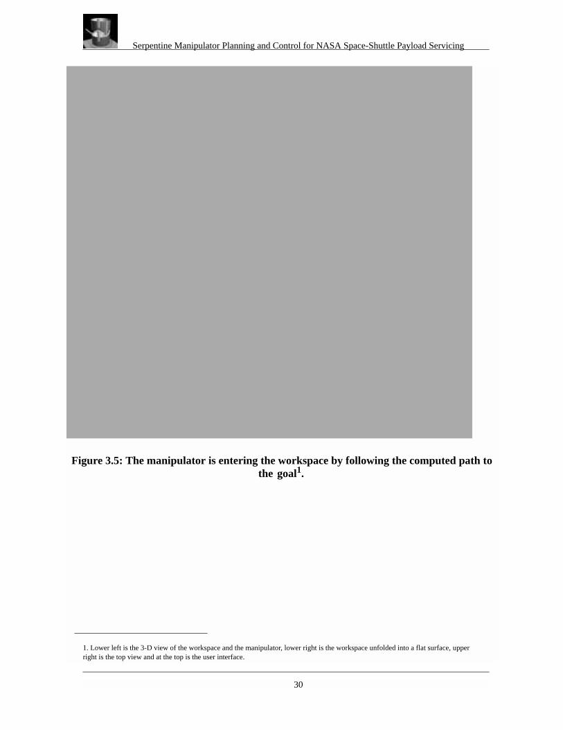
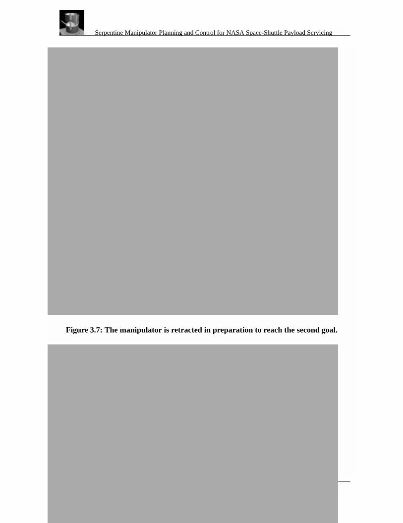
The individual operating modes and the resulting manipulator configurations within thespace-shuttle’s cargo-bay are outlined below and depicted in Figure 3.5 through Figure 3.8.
3.7.1 Teleoperation
The use of the snake allows us to teleoperate the robot easily without having to control all thejoint angles individually by allowing the operator to pick which points he/she wants to control.This is possible since the operator controls the snake directly, and he/she only controls the manip-ulator indirectly. Since the snake is always repulsed from an obstacle, the operator does not needto worry about collisions. The operator also has one direct control avenue over the manipulator,namely the ability to retract or extend the manipulator along the snake. Besides applying forces tothe snake, the operator can also ‘nail’ points down on the snake. Nailing a point on the snakemakes that point immovable. The two end points of the snake are also always nailed (one to thebase and one to the goal), forcing the snake to acquire the final goal position with additional con-straints.
U r( ) A2---
1r---
1r0-----–
2= 0 r r0< <
Serpentine Manipulator Planning and Control for NASA Space-Shuttle Payload Servicing
29
3.7.2 Automatic Operation
In addition to teleoperation of the robot, the operator can also give the system a goal and it willplan a path to the goal automatically. If the operator wants the robot to approach the goal from acertain opening or access port, then the operator can put an intermediate goal-point near the open-ing and then set the planning system so the path to the new goal will be the shortest path startingfrom the old goal. This means that we want the path that minimizes the distance that the tip of themanipulator has to travel. After the manipulator reaches the intermediate goal, the operator caninstruct it to go to the real goal. If the manipulator is required to pass through a certain point in theopening, the snake can be ‘nailed’ at that point.
3.7.3 Scanning
Sometimes it is necessary for the end point to follow a predetermined path, for example to scanthe outside cylindrical surface of a payload installed inside the space-shuttle’s cargo-bay (visualclose-out inspection). In this case no path generation is necessary, assuming that the control pointsin the pre-determined path are located close to one another. To move the endpoint of the manipu-lator along this path, we just need to move the end point of the snake along the path. We move theend point of the snake by fixing it to the next control point along the path. The rest of the snakewill then move accordingly to minimize its overall energy.
Serpentine Manipulator Planning and Control for NASA Space-Shuttle Payload Servicing
30
Figure 3.5: The manipulator is entering the workspace by following the computed path to the goal1.
1. Lower left is the 3-D view of the workspace and the manipulator, lower right is the workspace unfolded into a flat surface, upper right is the top view and at the top is the user interface.

Serpentine Manipulator Planning and Control for NASA Space-Shuttle Payload Servicing
31
Figure 3.6: The manipulator has reached its first goal.
Serpentine Manipulator Planning and Control for NASA Space-Shuttle Payload Servicing
32
Figure 3.7: The manipulator is retracted in preparation to reach the second goal.

Serpentine Manipulator Planning and Control for NASA Space-Shuttle Payload Servicing
33
4. References
[1] M. Kass, A. Witkin and D. Terzopoulos “Snakes: Active contour models.” International Jour-nal of Computer Vision 1,1987, 321-331.
[2] O. Khatib “Real-time obstacle avoidance for manipulators and mobile robots.” The Interna-tional Journal of Robotics Research, 5(1), 1986.
[3] J. Barraquand, B. Langlois and J. Latombe “Robot motion planning with many degrees offreedom and dynamic constraints.”
[4] A. Hayashi and B.J. Kuipers “Obstacle avoidance of the swan’s neck manipulator.” TechnicalReport AI90-142, Artificial Intelligence Laboratory, the University of Texas at Austin, Octo-ber 1990.
[5] R. Volpe and P. Khosla “A strategy for obstacle avoidance and approach using superquadricpotential functions.”
[6] J.J. Craig “Introduction to robotics.”[7] NASA/KSC Study, “Payload Processing System Study”, KSC-DM-3489, October 1990, Engi-
neering Development Directorate[8] NASA/KSC Space Transportation Systems Study, “Payload Accommodations at the Rotating
Service Structure”, K-STSM-14.1.10, Rev. B, December 1980, Space Shuttle PayloadProjects