SERIES Z 24 - EasyGates Ltdmanuals.easygates.co.uk/PDF/CAME/ZL90_319U16_ver05_EN.pdf... Fucntions...
18
Z 24 SERIES INSTALLATION MANUAL ZL90 CONTROL PANEL FOR 24V OPERATORS English EN
Transcript of SERIES Z 24 - EasyGates Ltdmanuals.easygates.co.uk/PDF/CAME/ZL90_319U16_ver05_EN.pdf... Fucntions...

Z 24
SERI
ES
INSTALLATION MANUAL
ZL90
CONTROL PANELFOR 24V OPERATORS
English EN

Pag.
2 -
Man
ual c
ode:
319
U16
319U
16 v
er. 0
.0.5
09/
2007
© C
AME
canc
elli
auto
mat
ici s
.p.a
. - T
he d
ata
and
info
rmat
ion
repo
rted
in th
is in
stal
latio
n m
anua
l are
sus
cept
ible
to c
hang
e at
any
tim
e an
d w
ithou
t obl
igat
ion
on C
AME
canc
elli
auto
mat
ici s
.p.a
. to
notif
y us
ers.
EN
GLIS
H
Make sure you respect the distances and cable diameters as shown in “cable types and minimal thicknesses” table. The overall power of the motors must not exceed 480W.
4 Description
2.1 - INTENDED USE
1 Legend of symbols
This symbol indicates sections to be read with particular care.
This symbol indicates sections concerning safety
This symbol indicates notes to communicate to users.
2 Intended use and application
The ZL90 control panel is designed to control the FROGJ and A1824 swing gate operators
The use of this product for purposes other than as described above and installation executed in a manner other than as instructed in this technical manual are prohibited.
3 Reference Standards
“IMPORTANT INSTALLATION, SAFETY INSTRUCTIONS”
“CAUTION: IMPROPER INSTALLATION MAY CAUSE SERIOUS DAMAGE, FOLLOW ALL INSTALLATION INSTRUCTIONS CAREFULLY”
“THIS MANUAL IS ONLY FOR PROFESSIONAL INSTALLERS OR QUALIFIED PERSONS”
2.2 - APPLICATION
For its quality processes management Came Cancelli Automatici is ISO 9001:2000 certified, and for its environmental management it is ISO 14001 certified. Came designs and manufactures entirely in Italy.This product complies with the following standards: see chapter 13 - Conformity declaration - pag. 17.
FUSESprotection fuse type
Motor/s 6.3 A-F
Electronic board (power supply line) 1.6 A-F
Accessories 1.6 A-F
Control devices 1 A-F
TECHNICAL FEATURES
Power supply 230V - 50/60Hz
max. rated power 480 W
Power draw when idling 90 mAMax power of 24V accessories 37 W
Insulation rating IIMaterial ABS
Protection rating IP54
operating temperature -20 / +55°C
This product is engineered and manufactured by CAME cancelli automatici s.p.a. and complies with current safety regulations.Guaranteed 24 months if not tampered with.The control panel works on 230V a.c. of power, through the terminals L-N, 50/60Hz frequency.Both command and control devices and accessories are 24V powered. Warning! Accessories must not exceed 37 W overall.The control unit is fi tted with an amperometric device which con-stantly regulates the motor’s drive coeffi cient.When the gate runs into an obstacle, the amperometric sensor immediately detects an overcharge in the drive and redirects the gate’s direction of movement, and:
- opens it if it is closing(1)
;- closes it if it is opening.
(1) Warning!: in this case, after 3 consecutive obstacle detections, the gate will stop open excluding the automatic closing function; for movement to start again press the command button or use the remote control.
All connections are protected by quick fuses, see table.The card provides and controls the following functions:
- automatic closing after an open-command;- pre-fl ashing by the motion indicator;- obstacle detection when gate is still in any position;- continual monitoring of photocell operation.
The following command modes are possible:- open/close;- open/close and maintained action;- partially open;- complete stop.
After detecting an obstacle and depending on the type of con-nection used, the photocells may cause:
- reopening of the gate when it is closing;- partial stop or obstacle stand-by.
Apposite trimmers regulate:- the automatic closing run time;- the second gate leaf’s motion time difference;- the amperometric device’s detection sensitivity, in sepa-rately in terms of normal opening and closing and braking;- the operation and deceleration speed separately.
Further implemented options:- connecting up an electric lock (alternatively to the “Open Gate” indicator light) and possibly adding the “Ram Blow” function.

12
1
7 85
16
6 9
2
3
4
14 1315
11
10
Pag.
3 -
Man
ual c
ode :
319
U16
319U
16 v
er. 0
.0.5
09/
2007
© C
AME
canc
elli
auto
mat
ici s
.p.a
. - T
he d
ata
and
info
rmat
ion
repo
rted
in th
is in
stal
latio
n m
anua
l are
sus
cept
ible
to c
hang
e at
any
tim
e an
d w
ithou
t obl
igat
ion
on C
AME
canc
elli
auto
mat
ici s
.p.a
. to
notif
y us
ers.
EN
GLIS
H
4.1 - DIMENSIONS, SPANS AND ANCHORING HOLES
4.2 - MAIN COMPONENTS
1) Transformer
2) M1 motor fuse
3) M2 motor fuse
4) Line fuse
5) Accessories fuse
6) Control unit fuse
8) Buttons for calibrating the stroke
8) Buttons for memorising the radio code
9) Control and signalling LED unit
10) Functions selectors (2 way)
11) Fucntions selector (10 way)
12) Plug for the remote control frequency card
13) terminal board for connecting the antenna
14) Terminal board for connecting accessories and control devices
15) Terminal board for connecting the gearmotors
16) Terminal board for 230V a.c. power grid
Warning! Before acting on the machinery, cut off the main power supply and disconnect any emergency batteries.

!!
Pag.
4 -
Man
ual c
ode:
319
U16
319U
16 v
er. 0
.0.5
09/
2007
© C
AME
canc
elli
auto
mat
ici s
.p.a
. - T
he d
ata
and
info
rmat
ion
repo
rted
in th
is in
stal
latio
n m
anua
l are
sus
cept
ible
to c
hang
e at
any
tim
e an
d w
ithou
t obl
igat
ion
on C
AME
canc
elli
auto
mat
ici s
.p.a
. to
notif
y us
ers.
EN
GLIS
H
Before installing do the following:
• Check that the panel’s anchoring point is protected from possible blows, and that the anchoring surface is solid. Also check that the anchoring is done using the appropriate bolts, screws etc.
• Make sure you have a suitable omnipolar cut-off device with contacts more than 3 mm apart, and independent (sectioned off) power supply.
• Make sure that any connections inside the case (that provide continuance to the protective circuit) are fitted with extra insulation as compared to the other conductive parts inside;
• Make sure you have suitable tubing and conduits for the electrical cables to pass through and be protected against mechanical damage.
Make sure you have all the tools and materials you will need for the installation at hand to work in total safety and compliance with the current standards and regulations. The following figure illustrates the minimum equipment needed by the installer.Here are some examples.
Fix the base of the panel in a protected area; we suggest using round top Phillips recessed head screws of max. 6mm in diameter.
5.3 - FIXING AND MOUNTING THE BOX
Perforate the pre-punched holes and insert the cable glands with the corrugated tubing for the electrical cables to travel throughN.B.: the pre-punched holes have the following diameters:23m 29 and 37 mm.
Assemble the pressure hinges.
5 Installation
5.1 - PRELIMINARY CHECKS
5.2 - TOOLS AND MATERIALS

15 mm~
Pag.
5 -
Man
ual c
ode :
319
U16
319U
16 v
er. 0
.0.5
09/
2007
© C
AME
canc
elli
auto
mat
ici s
.p.a
. - T
he d
ata
and
info
rmat
ion
repo
rted
in th
is in
stal
latio
n m
anua
l are
sus
cept
ible
to c
hang
e at
any
tim
e an
d w
ithou
t obl
igat
ion
on C
AME
canc
elli
auto
mat
ici s
.p.a
. to
notif
y us
ers.
EN
GLIS
H
After the adjustments and settings, fix the cover using the provided screws.
Insert the pressure hinges into the box (on the left or right as you wish) and set them using the provided screws and washers
Snap the cover into place onto the hinges. Close it and fix it using the provided screws
6.1 - CABLE LIST AND MINIMUM THICKNESSES
N.B.: If the cable length differs from that specified in the table, then you must determine the proper cable diameter based on the actual power draw from the connected devices and according to the CEI EN 60204-1 standards.For connections that require several, sequential loads, the sizes given on the table must be re-evaluated based on actual power draw and distances.When connecting products that are not specified in this manual, please follow the documentation provided with said products.
Connections Type of cable
Length of cable1 < 10 m
Length of cable10 < 20 m
Length of cable 20 < 30 m
Control panel power supply 230V
FROR CEI 20-22
CEI EN 50267-2-1
3G x 1,5 mm2 3G x 2,5 mm2 3G x 4 mm2
Motor power supply 24V 3 x 1 mm2 3 x 1,5 mm2 3 x 2,5 mm2
flashing lamp 2 x 0,5 mm2 2 x 1 mm2 2 x 1,5 mm2
Transmitter photocells 2 x 0,5 mm2 2 x 0.5 mm2 2 x 0,5 mm2
Receiver photocells 4 x 0,5 mm2 4 x 0,5 mm2 4 x 0,5 mm2
Power supply to accessories 2 x 0,5 mm2 2 x 0,5 mm2 2 x 1 mm2
Control and safety devices 2 x 0,5 mm2 2 x 0,5 mm2 2 x 0,5 mm2
Antenna connection RG58 max. 10 m
6 Electrical connections

Pag.
6 -
Man
ual c
ode:
319
U16
319U
16 v
er. 0
.0.5
09/
2007
© C
AME
canc
elli
auto
mat
ici s
.p.a
. - T
he d
ata
and
info
rmat
ion
repo
rted
in th
is in
stal
latio
n m
anua
l are
sus
cept
ible
to c
hang
e at
any
tim
e an
d w
ithou
t obl
igat
ion
on C
AME
canc
elli
auto
mat
ici s
.p.a
. to
notif
y us
ers.
EN
GLIS
H
+ -
Power supply230V (a.c.) 50/60 Hz
Terminals for powering the following accessories:- 24V a.c. (normally alternated power)- 24V a.c. (continuous power) when the emergency batte-ries are in operation.Overall power allowed: 37W
6.3 - POWER SUPPLY TO ACCESSORIES
FROG-J / A1824
M2 - 24V d.c. gearmotor featuring delayed action on closing
6.2 - CONNECTING TO THE GEARMOTORS
FROG-J / A1824
M1 - 24V d.c. gearmotor featuring delayed action on opening
BLACKBROWN
BLUE
BLUEBLACKBROWN

Pag.
7 -
Man
ual c
ode :
319
U16
319U
16 v
er. 0
.0.5
09/
2007
© C
AME
canc
elli
auto
mat
ici s
.p.a
. - T
he d
ata
and
info
rmat
ion
repo
rted
in th
is in
stal
latio
n m
anua
l are
sus
cept
ible
to c
hang
e at
any
tim
e an
d w
ithou
t obl
igat
ion
on C
AME
canc
elli
auto
mat
ici s
.p.a
. to
notif
y us
ers.
EN
GLIS
HSignal Flasher
(socket rating: 24V - 25W max.) Flashes during opening and closing phases
Open gate indicator-light (socket rating: 24V - 3W max.).Turns on when the gate is ajar or open. It turns off when the gate is closed.(Also see Chapt. 6.4)
6.5 - SIGNALLING AND LIGHTING DEVICES
6.4 - ELECTRICAL LOCK
After hooking it up as shown in the illustration, proceed as follows:
a) - Set dip switch 6 to ON (and dip switch 3 to OFF);;b) - press CH1: the red PROG led will start to blink;c) - when the led stays on (after about 5 seconds) the procedure is complete;d) - set to the dip switches back to OFF (or to the previous position, which depends on the functions selection, see paragraph 7, page 10).
N.B.: to return to default (indicator lamp on 10-5), follow the same procedure while pressing CH2.
ZL90 allows you to connect, alternatively to the indicator light on 10-5, a 12V (15W max) electrolock, and if necessary also the “Ram Blow” function.
a)To activate the “ram blow” (1):
aa) - Set ) - Set dip switches 3 and 6 to ONdip switches 3 and 6 to ON;;bb), ), cc), ), dd) - continue with the above ) - continue with the above COMMON PROCEDURCOMMON PROCEDURE.
N.B.: to exclude the ram blow, follow the same procedure while pressing CH2.(1) Upon each opening command, the gate leaves press on the closing jamb for one second, assisting the electrolock release operation.
5
place a 3.15 A
fuse in between
17V transformer terminal
a)
b)
COMMON PROCEDURE
d)c)
RX TX
TXRX
TXRX
RX TX
Pag.
8 -
Man
ual c
ode:
319
U16
319U
16 v
er. 0
.0.5
09/
2007
© C
AME
canc
elli
auto
mat
ici s
.p.a
. - T
he d
ata
and
info
rmat
ion
repo
rted
in th
is in
stal
latio
n m
anua
l are
sus
cept
ible
to c
hang
e at
any
tim
e an
d w
ithou
t obl
igat
ion
on C
AME
canc
elli
auto
mat
ici s
.p.a
. to
notif
y us
ers.
EN
GLIS
H
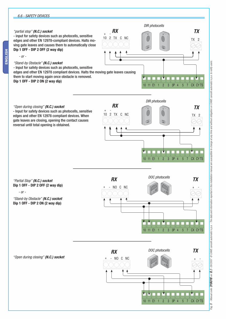
6.6 - SAFETY DEVICES
“Open during closing” (N.C.) socket - Input for safety devices such as photocells, sensitive edges and other EN 12978 compliant devices. When gate leaves are closing, opening the contact causes reversal until total opening is obtained.
“partial stop” (N.C.) socket - input for safety devices such as photocells, sensitive edges and other EN 12978-compliant devices. Halts mo-ving gate leaves and causes them to automatically close Dip 1 OFF - DIP 2 OFF (2 way dip)
- or -
“Stand-by Obstacle” (N.C.) socket - Input for safety devices such as photocells, sensitive edges and other EN 12978 compliant devices. Halts the moving gate leaves causing them to start moving again once obstacle is removed.Dip 1 OFF - DIP 2 ON (2 way dip)
“Open during closing” (N.C.) socket
“Partial Stop” (N.C.) socket Dip 1 OFF - DIP 2 OFF (2 way dip)
- or -
“Stand-by Obstacle” (N.C.) socket Dip 1 OFF - DIP 2 ON (2 way dip)
DIR photocells
DOC photocells
DIR photocells
DOC photocells

Pag.
9 -
Man
ual c
ode :
319
U16
319U
16 v
er. 0
.0.5
09/
2007
© C
AME
canc
elli
auto
mat
ici s
.p.a
. - T
he d
ata
and
info
rmat
ion
repo
rted
in th
is in
stal
latio
n m
anua
l are
sus
cept
ible
to c
hang
e at
any
tim
e an
d w
ithou
t obl
igat
ion
on C
AME
canc
elli
auto
mat
ici s
.p.a
. to
notif
y us
ers.
EN
GLIS
H
At each opening and closing command, the control board assesses the effi ciency status of the control devices (photocells). Any anomaly found is signalled with the fl ashing of the (PROG) LED on the control panel. Consequently it cancels any commands coming from the remote control or the button.
Electrical connection to enable the photocell safety test:- the transmitter and the receiver, must be connected as per the diagram;- set DIP switch 8 to ON to activate test operation.
IMPORTANT: when running the safety test function, the N.C. contacts, if unused, should be excluded on the relative DIP switches (see chapter 7 “selecting functions”).
6.8 - ELECTRICAL CONNECTION FOR THE PHOTOCELLS FUNCTIONS TEST
(DOC) (DIR)
Pulsante Stop button (N.C. socket) - PulsanteButton to stop gate while excluding the automatic closing cycle. For movement to resume you must press the command button or transmitter button.
Key selector and/or opening button (N.O. socket) - Gate opening command.
Key selector and/or commands button (N.O. contact) - Gate closing and opening contacts, by pressing the button or turning the selector key, the gate movement is inverted or halted depending on which selection was just made. (see selecting func-tions, dips 2 and 3).
Key selector and/or partial opening button (N.O. socket)- Opening of one gate leaf to allow pedestrian passage.
Key selector and/or closing button (N.O. contact) - gate closing command.
6.7 - COMMAND DEVICES

ONOFF
1 2 3 4 5 6 7 8 9 10
ON
ONOFF
1 2
ON
Pag.
1010
- M
anua
l cod
e: 3
19U1
631
9U16
ver
. 0.0.5
09/
2007
© C
AME
canc
elli
auto
mat
ici s
.p.a
. - T
he d
ata
and
info
rmat
ion
repo
rted
in th
is in
stal
latio
n m
anua
l are
sus
cept
ible
to c
hang
e at
any
tim
e an
d w
ithou
t obl
igat
ion
on C
AME
canc
elli
auto
mat
ici s
.p.a
. to
notif
y us
ers.
EN
GLIS
H
10 WAY DIP SWITCH
2 WAY DIP SWITCH
1 OFF Enables the obstacle stand-by or partial stop function; connect the safety device to terminals [2-CY]. If device is unused, set the DIP switch to ON;
1 OFF - 2 ON Obstacle stand-by – stops the gate when there is an obstacle is detected by the safety device; once the obstacle has been cleared, the gate is automatically set back in motion to finish initial run. Connect the safety devices to terminal [2-CY];
1 OFF - 2 OFF Partial stop – stops gate when an obstacle is detected by the safety devices; once the obstacle is cleared, the gate remains still or closes if the automatic closing function is enabled. Connect the safety devices to terminal [2-CY];
1 ON - Automatic closing - the automatic closing timer is activated when on opening the gate leaf has reached the full open stroke. The time is preset and adjustable, and is subject to the action of any safety devices. It does not activate after a total safety “stop” or during a power outage;
2 ON - “Open-stop-close-stop” function with button [2-7] and remote control (with built-in radiofrequency card);
2 OFF - “open-close-inversion” function with button [2-7] and remote control (with built-in radiofrequency card);
3 ON - “Open only” function with remote control (featuring built-in radiofrequency card);
4 ON - Pre-Flashing during opening and closing - Following an opening or closing command, the flasher connected to [10-E], flashes for 5 seconds before initiating the operation;
5 ON - Obstacle detection - When motor is idle (gate closed, open or after a total stop command), it prevents any motion if the safety devices (e.g. photocells) detect any obstacle;
6 ON - Maintained action - the gate works by keeping the button pressed (one button [2-3] for opening, and one button [2-4] for closing);
7 ON - Enables to the command of A1824 operators;
7 OFF - Enables to the command of FROG J operators;
8 ON - Operation of the photocells safety test - this allows the card to assess the efficiency of the safety devices (photocells) after each opening and closing command;
9 OFF - Total stop - this function halts the gate, consequently excluding any closing cycle; press buttons or remote control to set back in motion. Insert safety devices on 1-2]; if not used, set DIP switch to ON;
10 OFF - Reopening during closing - if the photocells detect an obstacle during gate closing, the gate motion is inverted until total opening is reached; connect the safety device to terminals [2-CX];
NB -Dip switches 3 and 6 are used, independently, also to activate the electrolock and ram blow (page 7).
7 Selecting functions

Pag.
1111
- M
anua
l cod
e : 3
19U1
631
9U16
ver
. 0.0.5
09/
2007
© C
AME
canc
elli
auto
mat
ici s
.p.a
. - T
he d
ata
and
info
rmat
ion
repo
rted
in th
is in
stal
latio
n m
anua
l are
sus
cept
ible
to c
hang
e at
any
tim
e an
d w
ithou
t obl
igat
ion
on C
AME
canc
elli
auto
mat
ici s
.p.a
. to
notif
y us
ers.
EN
GLIS
H
8 Adjustments
LIST OF CONTROL LED SIGNALS OF THE COMMAND AND SAFETY DEVICES:
- «PROG» Red coloured LED. Usually off. It turns on or fl ashes when the transmitter is activating or when the system is memorising automatic adjustment.
- «ALIM» Green coloured LED. Usually on. It signals proper power supply to the card.
- «STOP» Yellow coloured LED. Usually off. Signals that the TOTAL STOP button is engaged.
- «CX/TH» Yellow coloured LED. Usually off. Warns of objects present between the photocells (that are set to the REOPEN DURING CLOSING function).
- «CY» Yellow coloured LED. Usually off. Warns of objects present between the photocells (that are set to the PARTIAL STOP or OBSTACLE STAND-BY function).
Led CY
Led PROG
Led ALIM.
Led STOP
Led CX/TH.
9 Signal LED
Trimmer ACT
Adjusts the waiting time when gate is open. Once this time has elapsed, the gate closes automatically. The waiting time can be adjusted anywhere between 1 and 150 seconds.
Trimmer DELAY 2M
Adjustes the waiting time of the second motor during each closing run. The waiting time can be adjusted anywhere between 1 and 16 seconds.
Trimmer -- SENS --
RUN
Adjusts the amperometric sensitivity which controls the power developed by the motor during motion; if the power exceeds the adjusted level, the system sets in motion to invert the direction of motion.
Trimmer -- SENS -- SLOWING
Adjusts the amperometric sensitivity which controls the power developed by the motor during slowing downs; if the power exceeds the adjusted level, the system sets in motion to invert the direction of motion.
Trimmer -- SPEED --
RUN
Adjusts the gate-leaf running speed when opening or closing.
Trimmer -- SPEED --
SLOWING
Adjusts the gate leaf’s slowing speed at the end of the stroke when opening and closing.

FROG J
A1824 A1824
FROG J
7OFF = FROG J7ON = A1824
Pag.
1212
- M
anua
l cod
e: 3
19U1
631
9U16
ver
. 0.0.5
09/
2007
© C
AME
canc
elli
auto
mat
ici s
.p.a
. - T
he d
ata
and
info
rmat
ion
repo
rted
in th
is in
stal
latio
n m
anua
l are
sus
cept
ible
to c
hang
e at
any
tim
e an
d w
ithou
t obl
igat
ion
on C
AME
canc
elli
auto
mat
ici s
.p.a
. to
notif
y us
ers.
EN
GLIS
H
10 Automatic calibration of the gate run
- Release both gearmotors (see paragraph on “manual release” in the installation manual), position the gate leaves to be half-way open, block the gearmotors again.
10.1 - PRELIMINARY ASSESSMENT OF THE DIRECTION OF MOVEMENT DURING OPENING
Otherwise:
1) if the gate leaves close, invert the M-N phases on either of the gearmotors;
2) if the gate leaf of the fi rst gearmotor closes, invert the M1-N1 phase.
3) if the gate leaf of the second gearmotor closes, invert the M2-N2 phase
Warning! With single-leaf gates, connect the gearmotor to terminals M2-N2-ENC2.
The calibration procedures are the same as those described below
Warning! For Frog J, set Dip switch n. 7 to OFF. For A1824, set DIP switch n. 7 to ON.Briefl y press the “OPEN MOTOR” button. Check that both gate leaves perform the opening movement.

Pag.
1313
- M
anua
l cod
e : 3
19U1
631
9U16
ver
. 0.0.5
09/
2007
© C
AME
canc
elli
auto
mat
ici s
.p.a
. - T
he d
ata
and
info
rmat
ion
repo
rted
in th
is in
stal
latio
n m
anua
l are
sus
cept
ible
to c
hang
e at
any
tim
e an
d w
ithou
t obl
igat
ion
on C
AME
canc
elli
auto
mat
ici s
.p.a
. to
notif
y us
ers.
EN
GLIS
H
10.2 - PROCESS FOR AUTOMATIC CALIBRATION OF THE GEARMOTORS
- The gate leaf of the second gearmotor perform a closing run and an opening run, ...
- With gate leaves fully ope, the PROG LED stays on for some seconds to show the proper automatic calibration. If the LED fl ashes check the connections and repeat the calibration procedure.
- Press the “SET UP” button for about 3 seconds.
...Then, the gate leaf of the the fi rst gearmotor performs the same runs.
- Position the gate leaves so that they are half-way open by pressing on the “OPEN MOTOR” button.

Pag.
1414
- M
anua
l cod
e: 3
19U1
631
9U16
ver
. 0.0.5
09/
2007
© C
AME
canc
elli
auto
mat
ici s
.p.a
. - T
he d
ata
and
info
rmat
ion
repo
rted
in th
is in
stal
latio
n m
anua
l are
sus
cept
ible
to c
hang
e at
any
tim
e an
d w
ithou
t obl
igat
ion
on C
AME
canc
elli
auto
mat
ici s
.p.a
. to
notif
y us
ers.
EN
GLIS
H
11 Activating the remote control
AF card
Lock the radiofrequency card into the electronic card AFTER CUTTING OFF THE POWER SUPPLY (or after disconnecting the batte-ries).N.B.: the electronic card only recognises the radiofrequency card when the power is on.
Connect the antenna’s RG58 cable to the apposite terminals.
11.1 - ANTENNA
11.2 - RADIOFREQUENCY CARD
Possible output of the radio receiver’s second channel (N.O. socket). Socket rating: 5A-24V (d.c.).

Pag.
1515
- M
anua
l cod
e : 3
19U1
631
9U16
ver
. 0.0.5
09/
2007
© C
AME
canc
elli
auto
mat
ici s
.p.a
. - T
he d
ata
and
info
rmat
ion
repo
rted
in th
is in
stal
latio
n m
anua
l are
sus
cept
ible
to c
hang
e at
any
tim
e an
d w
ithou
t obl
igat
ion
on C
AME
canc
elli
auto
mat
ici s
.p.a
. to
notif
y us
ers.
EN
GLIS
H
11.3 - TRANSMITTERS
CAME
CAMECAME
CAME
CAME
CAME
CAME
CAME
CAME
CAME
TOUCH
TCH 4024 • TCH 4048
TOP
TOP-432NA • TOP-434NATOP-432S
TOP
TOP-302A • TOP-304ATOP
TOP-432A • TOP-434A
TAM
T432 • T434 • T438 TAM-432SA
TFM
T132 • T134 • T138T152 • T154 • T158
CAMECAME
CAME
ATOMO
AT01 • AT02AT04
CAME
CAMECAME
See a
ttach
ed in
struc
tions
See instructions attached to AF43SR radiofrequency card
TWIN
TWIN2 • TWIN4
CH1
T1
T2
CH2
Pag.
1616
- M
anua
l cod
e: 3
19U1
631
9U16
ver
. 0.0.5
09/
2007
© C
AME
canc
elli
auto
mat
ici s
.p.a
. - T
he d
ata
and
info
rmat
ion
repo
rted
in th
is in
stal
latio
n m
anua
l are
sus
cept
ible
to c
hang
e at
any
tim
e an
d w
ithou
t obl
igat
ion
on C
AME
canc
elli
auto
mat
ici s
.p.a
. to
notif
y us
ers.
EN
GLIS
H
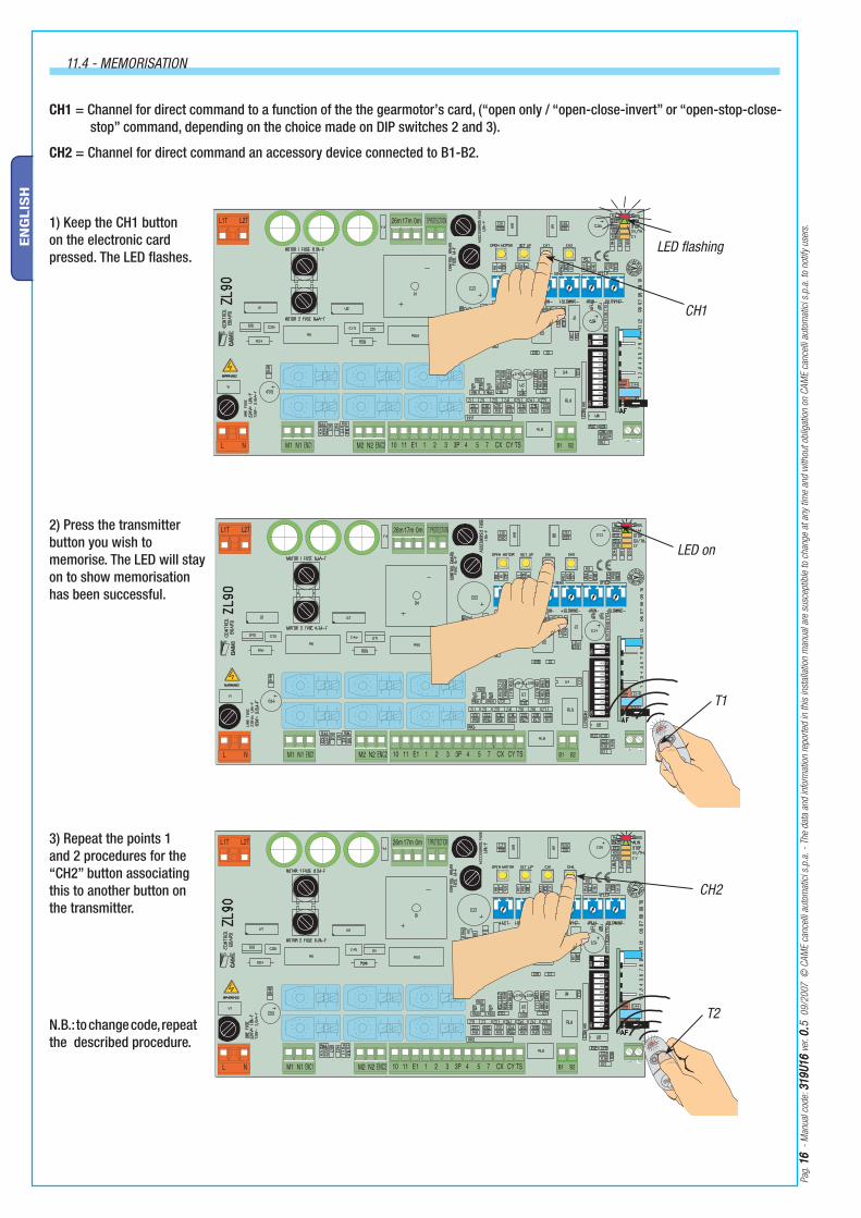
1) Keep the CH1 button on the electronic card pressed. The LED fl ashes.
2) Press the transmitter button you wish to memorise. The LED will stay on to show memorisation has been successful.
LED flashing
LED on
11.4 - MEMORISATION
CH1 = Channel for direct command to a function of the the gearmotor’s card, (“open only / “open-close-invert” or “open-stop-close-stop” command, depending on the choice made on DIP switches 2 and 3).
CH2 = Channel for direct command an accessory device connected to B1-B2.
N.B.: to change code, repeat the described procedure.
3) Repeat the points 1 and 2 procedures for the “CH2” button associating this to another button on the transmitter.

Pag.
1717
- M
anua
l cod
e : 3
19U1
631
9U16
ver
. 0.0.5
09/
2007
© C
AME
canc
elli
auto
mat
ici s
.p.a
. - T
he d
ata
and
info
rmat
ion
repo
rted
in th
is in
stal
latio
n m
anua
l are
sus
cept
ible
to c
hang
e at
any
tim
e an
d w
ithou
t obl
igat
ion
on C
AME
canc
elli
auto
mat
ici s
.p.a
. to
notif
y us
ers.
EN
GLIS
H
12 Phasing out and disposal
Our products are made with different types of materials. The majority of these (aluminium, plastic, iron and electrical cables) are part of the solid urban waste category. They can be recycled through licensed waste disposal plants.
Other components (electronic cards, remote control batteries, etc.) constitute hazardous waste. Thus, they are to be removed and delivered to licensed fi rms that specialise in their proper disposal.
MANUFACTURER’S DECLARATION OF CONFORMITYPursuant to annex II B of the Machinery Directive 98/37/EC
CAME Cancelli Automatici S.p.A. via Martiri della Libertà, 15 31030 Dosson di Casier - Treviso - ITALY tel (+39) 0422 4940 - fax (+39) 0422 4941 internet: www.came.it - e-mail: [email protected]
Declares under its own responsibility that the equipments for automatic garage doors and gates listed below:
ZL90
… comply with the National Law related to the following European Directives and to the applicable parts of the following Standards.
--- DIRECTIVES ---98/37/CE - 98/79/CE MACHINERY DIRECTIVE
98/336/CEE - 92/31/CEE ELECTROMAGNETIC COMPATIBILITY DIRECTIVE
73/23/CEE - 93/68/CE LOW VOLTAGE DIRECTIVE
89/106/CEE CONSTRUCTION PRODUCTS DIRECTIVE
--- STANDARDS ---EN 13241-1 EN 12635 EN 61000-6-2 EN 12453 EN 12978 EN 61000-6-3 EN 12445 EN 60335-1
IMPORTANT WARNING!Do not use the equipment specifi ed here above, before completing the full installationIn full compliance with the Machinery Directive 98/37/EC
MANAGING DIRECTORMr. Andrea Menuzzo
13 Conformity declaration
Reference code to request a true copy of the original: DDF B EN A001C

CAME France S.a.CAME France S.a.7, Rue Des HarasZ.i. Des Hautes Patures92737 Nanterre Cedex - Nanterre Cedex - FRANCE
(+33) 1 46 13 05 05 (+33) 1 46 13 05 00
CAME Gmbh SeefeldCAME Gmbh SeefeldAkazienstrasse, 9
16356 Seefeld Seefeld Bei Berlin - DEUTSCHLAND
(+49) 33 3988390 (+49) 33 39883985
CAME Automatismes S.a.CAME Automatismes S.a.3, Rue Odette Jasse13015 Marseille - Marseille - FRANCE
(+33) 4 95 06 33 70 (+33) 4 91 60 69 05
CAME GmbhCAME GmbhKornwestheimer Str. 37
70825 Korntal Korntal Munchingen Bei Stuttgart - DEUTSCHLAND
(+49) 71 5037830 (+49) 71 50378383
CAME Automatismos S.a.CAME Automatismos S.a.C/juan De Mariana, N. 17-local28045 Madrid - Madrid - SPAIN
(+34) 91 52 85 009 (+34) 91 46 85 442
CAME Americas Automation LlcCAME Americas Automation Llc1560 Sawgrass Corporate Pkwy, 4th Floor
SunriseSunrise, FL 33323 - U.S.A (+1) 305 433 3307 (+1) 305 396 3331
CAME Automatismos Catalunya S.a.CAME Automatismos Catalunya S.a.P.i. Moli Dels Frares N. 23 C/a08620 Sant Vicenc Del Horts - Sant Vicenc Del Horts - SPAIN
(+34) 93 65 67 694 (+34) 93 67 24 505
CAME Middle East FzcoCAME Middle East FzcoPo Box 17131 Warehouse N. Be02
South Zone - Jebel Ali Free Zone - Dubai - Dubai - U.A.E. (+971) 4 8860046 (+971) 4 8860048
Paf - CAMEPaf - CAMEEstrada Nacional 249-4 Ao Km 4,35Cabra Figa - Trajouce2635-047 Rio De Mouro - Rio De Mouro - PORTUGAL
(+351) 219 257 471 (+35) 219 257 485
CAME Polska Sp.Zo.oCAME Polska Sp.Zo.oUl. Ordona 1
01-237 Warszawa - Warszawa - POLAND (+48) 22 8365076 (+48) 22 8363296
CAME United Kingdom Ltd.CAME United Kingdom Ltd.Unit 3 Orchard Business ParkTown Street, SandiacreNottingham Nottingham - Ng10 5du - UNITED KINGDOM
(+44) 115 9210430 (+44) 115 9210431
S.c. CAME Romania S.r.l.S.c. CAME Romania S.r.l.B-dul Mihai Eminescu, Nr. 2, Bloc R2
Scara A, Parter, Ap. 3Buftea, Judet Ilfov Bucarest - Bucarest - ROMANIA
(+40) 21 3007344 (+40) 21 3007344
CAME Belgium SprlCAME Belgium SprlZoning Ouest 77860 Lessines - Lessines - BELGIUM
(+32) 68 333014 (+32) 68 338019
CAME RussiaCAME RussiaLeningradskij Prospekt, Dom 80
Pod’ezd 3, offi ce 608125190, MoskvaMoskva - RUSSIA
(+7) 495 937 33 07 (+7) 495 937 33 08
CAME Cancelli Automatici S.p.a.CAME Cancelli Automatici S.p.a.Via Martiri Della Libertà, 1531030 Dosson Di Casier Dosson Di Casier (Tv)
(+39) 0422 4940 (+39) 0422 4941
Informazioni Commerciali 800 848095www.came.it
CAME Nord s.r.l.CAME Nord s.r.l.Piazza Castello, 16
20093 Cologno Monzese Cologno Monzese (MI) (+39) 02 26708293 (+39) 02 25490288
CAME Service Italia S.r.l.CAME Service Italia S.r.l.Via Della Pace, 2831030 Dosson Di Casier Dosson Di Casier (Tv)
(+39) 0422 383532 (+39) 0422 490044
Assistenza Tecnica 800 295830Assistenza Tecnica 800 295830
CAME Sud s.r.l.CAME Sud s.r.l.Via F. Imparato, 198
Cm2 Lotto A/7 80146 Napoli Napoli
(+39) 081 7524455 (+39) 081 7529109
Engl
ish
Engl
ish
- M
anua
l cod
e: 3
19U1
631
9U16
ver
. 0.0.5
09/
2007
© C
AME
canc
elli
auto
mat
ici s
.p.a
. Th
e da
ta a
nd in
form
atio
n re
porte
d in
this
inst
alla
tion
man
ual a
re s
usce
ptib
le to
cha
nge
at a
ny ti
me
and
with
out o
blig
atio
n on
CAM
E ca
ncel
li au
tom
atic
i s.p
.a. t
o no
tify
user
s.