Series P Linear Spring Cylinder Actuator · Series P Linear Spring Cylinder Actuator Engineering...
12
Series P Linear Spring Cylinder Actuator PRECISION I RELIABILITY I PERFORMANCE
Transcript of Series P Linear Spring Cylinder Actuator · Series P Linear Spring Cylinder Actuator Engineering...

Series P Linear Spring Cylinder Actuator
PRECISION I RELIABILITY I PERFORMANCE
06
01
07
09
08
10
1211
13
0204
03
05
16
17
18
19
20
1415
21

Contents
Series P Linear Spring Cylinder Actuator overview 01
Design features & performance benefits 02
Engineering data 02
Component list and materials of construction 04
Principles of operation 05
Air fail action 06
Improving actuator stroking speeds 07
Hand wheel operators 08
Standard dimensions & weights 09

Designed for fitting onto a wide range of control valves, louvres or dampers, these high power actuating units are for use in on/off, or modulating service. Their thrust capacity is much greater than similar size diaphragm spring actuators thanks to air pressures as high as 150psig (10bar) being used.
They operate either as a single, or double-acting unit and a range of springs is available to provide positive air fail action, which is field reversible. Positioners are normally yoke mounted and of the double-acting type providing air to both sides of the piston and giving a robust and precise unit that is resistant to load fluctuations and transients.
Series P Linear Spring Cylinder Actuators 01
SERIES
P ACTUATOR

Series P Linear Spring Cylinder Actuator
Engineering dataA range of compact, highly effective and reliable high-thrust pneumatic actuators, the Severn Glocon Series P is capable of working in the most punishing environments. Designed for use in on/off or modulating applications, they are capable of working up to 150psig (10bar) pressure.
Design features High thrust capability capable of using air supplies up to 150psig (10bar)
Multi-size options with long stroke capability
Robust components for trouble free, low cost ownership
Positive spring air fail action, which is field reversible
Lightweight corrosion resistant construction
Rotary options available
Performance benefits High degree of stem positioning accuracy
Cylinder design has lower air consumption than a comparable diaphragm actuator
Highly stable providing inherent stiffness over full stroke
Highly responsive with minimum latency on movement or positioning
High resolution of stem positioning for up to 5in strokes as standard with longer strokes available
Adjustable actuating forces to suit different applications
Rigorous in-field testing
Manufactured to ISO 9001 certification
02 Series P Linear Spring Cylinder Actuators
An internal spring allows for positive air fail action and the actuator is fully field reversible without any additional parts. The fitting of a yoke mounted double-acting positioner allows air to be fed to both sides of the piston, providing exceptionally stiff, precise movement, together with very high frequency response. This is of particular benefit to provide control where line pressure fluctuations are an issue.

Series P Linear Spring Cylinder Actuators 03
Engineering data (continued)
Ambient operating temperature
For standard materials: –20 °C to +80 °C. For special materials : –55 °C to +100 °C. For other operating temperatures please contact us.
Actuator sizes
The range includes four standard sizes: 25, 50, 100, 200in² (nominal piston area). Please contact us for more information on oversized actuators up to 600in².
Actuator strokes
Standard range up to 5in (see table 2 on page 4). For longer strokes please contact us.
Hand wheels
A range of geared handwheels for top or underside cylinder mounting is available.
Positioner input signals
Using yoke mounted external positioners, normally double acting type, 3-15psig (0.2-1.0bar), 4-20, digital. Also spilt ranges of the above signals. Digital “Smart” positioners are available.
Pneumatic supply pressure
Minimum 5psig (0.33bar) above calculated actuator requirement. Maximum to actuator is 150psig (10bar).
Operating supply gases
Air, nitrogen and oxygen. Options: methane (natural gas) filter regulator recommended to ensure clean supply.
Air fail action
Positive air fail action from internally mounted springs. Action is field reversible without additional parts.
Actuator mean thrust capability
Supply Pressure 150psig (10bar).
Hysterisis and linearity
Within +/- 1%.
Speed and sensitivity
Signal change of 0.01psig (0.013mA) reverses.
Actuator Thrust available
Size IbF kN
25 3,000 13.2
50 6,300 28.2
100 12,700 56.0
200 25,300 111.5
Table 1: Series P Linear Spring Cylinder Actuator – Cylinder and stem size details
25 0.75 20
25B 4.0 100
50 1.5 40
50B 2.5 63
100 2.5 63
100-5 5.0 125
100-6 6 150
100-12 12 300
100B 4.0 100
200-5 5.0 125
200-6 6.0 150
200-12 12.0 300
200B 5.0 125
0.75 1.90 0.44 2.80
1.38 3.50 1.48 9.70
1.25 3.17 1.23 7.70
1.38 3.50 1.48 9.70
105 1721
185 3032
295 4834
550 9013
930 15239
1320 21757
1820 29999
1820 29999
1120 18354
3340 54732
3340 54732
4740 77675
3340 54732
Actuator dimensions Effective area of cylinders Stem dimensions Maximumvolume
over pistonCylinder Stroke Bore diameter Upper area Lower area Stem diameter Stem area
Size in cm in cm in² cm² in² cm² ins cm in² cm² in³ cm³
Note: Suffix B denotes baseplate actuators used to operate butterfly valves or similar and are not normally used to operate globe or angle control valves.
6 15.2 28.3 182 27.8 179
6 15.2 28.3 182 27.8 179
8 20.3 50.3 325 49 316
8 20.3 50.3 325 49 316
12 30.5 113.1 729 111.3 718 1.5 3.81 1.76 11.60
12 30.5 113.1 729 111.3 718 1.5 3.81 1.76 11.60
12 30.5 113.1 729 111.3 718 1.5 3.81 1.76 11.60
12 30.5 113.1 729 111.3 718 1.5 3.81 1.76 11.60
12 30.5 113.1 729 111.3 718 1.5 3.81 1.76 11.60
16 40.6 197 1271 195 1258 2.25 5.72 3.98 25.70
16 40.6 197 1271 195 1258 2.25 5.72 3.98 25.70
16 40.6 197 1271 195 1258 2.25 5.72 3.98 25.70
16 40.6 197 1271 195 1258 2.25 5.72 3.98 25.70
04 Series P Linear Spring Cylinder Actuators
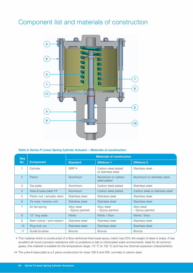
Component list and materials of construction
7
8
5
10
3
6
2
1
11
4
9
Key
Component
Materials of construction
No. Standard Offshore 1 Offshore 2
1 Cylinder GRP * Carbon steel plated Stainless steel or stainless steel
2 Piston Aluminium Aluminium or carbon Aluminium or stainless steel steel plated
3 Top plate Aluminium Carbon steel plated Stainless steel
4 Yoke & base plate ** Aluminium Carbon steel plated Carbon steel or stainless steel
5 Piston rod / actuator stem Stainless steel Stainless steel Stainless steel
6 Tie rods / tension unit Stainless steel Stainless steel Stainless steel
7 Air fail spring Alloy steel Alloy steel Alloy steel – Epoxy painted – Epoxy painted – Epoxy painted
8 “O” ring seals Nitrile Nitrile / Viton Nitrile / Viton
9 Stem clamp / anti rotation Stainless steel Stainless steel Stainless steel
10 Plug lock nut Stainless steel Stainless steel Stainless steel
11 Guide brushes Bronze Bronze Bronze
Table 2: Series P Linear Spring Cylinder Actuator – Materials of construction
* This material which is constructed of a fibre reinforced thermoset epoxy matrix has 25% the weight of steel or brass. It has excellent all round corrosion resistance with no problems in salt or chlorinated water environments. Ideal for all common gases, this material is suitable for the temperature range –73 °C to 132 °C and has low thermal expansion characteristics.
** The yoke & base plate is a 2 piece construction for sizes 100-5 and 200, normally in carbon steel.

Series P Linear Spring Cylinder Actuators 05
Principles of operationSeries P Linear Spring Cylinder Actuators do not require the internal spring for positioning when operated as a double acting unit through a positioner as the spring serves only as a fail-safe device. By fitting a spring with the appropriate thrust it is not necessary to utilise the valve flow direction to achieve the air fail position.
Table 3 below details the standard springs available for the Series P range. Whichever spring thrust is selected, the field reversibility of the actuator is unaffected.
Inherent actuator stiffness and stability
Actuator stiffness is defined as its ability to withstand suddenly changing dynamic forces acting on the valve trim as a result of varying process requirements. In order to be positioned accurately within the operator requirements, the actuator requires an inherent stiffness to minimise fluctuations in its position and this is achieved in the Series P range by delivering air to both sides of the cylinder piston.
The result is a vast improvement over typical spring opposed diaphragm units in which spring rates remain the same throughout the stroke.
For example when a valve is operated close to its seat with the flow over the plug, sudden changes in the dynamic force can cause the valve to “bath-plug” and slam shut if the actuator has insufficient stiffness. For this reason flow over the plug options are to be avoided in control applications when specifying spring opposed diaphragm actuators. By contrast, Series P products enable operation with the flow either over, or under, the valve plug with precise positioning under severe throttling conditions.
Table 4 (below) shows the maximum valve seating force available for standard spring and air pressure combinations, with the Series P Actuators built for air fail close and alternatively air fail open operation.
Note: Suffix B denotes baseplate actuators used to operate butterfly valves or similar.
Cylinder dimensions Spring to close Spring to open
Cylinder Stroke Spring Spring rate Spring Spring Spring Spring size (in) design (lb/in) extended (lb) retracted (lb) extended (lb) retracted (lb)
25 0.75 Standard 180 315 450 450 315 25 0.75 Heavy 445 778 1112 1112 778 25B 4.00 Standard 75 250 550 N/A N/A 50 1.50 Standard 164 328 574 574 328 50 1.50 Medium 398 796 1393 1393 796 50 1.50 Heavy 550 1092 1911 1911 1092 50B 4.00 Light 200 500 1300 N/A N/A 50B 4.00 Standard 200 800 1600 N/A N/A 100 2.50 Light 372 745 1675 1675 745 100 2.50 Standard 550 1100 2475 2475 1100 100 2.50 Heavy 700 1400 3150 3150 1400 100B 4.00 Standard 400 800 2400 N/A N/A 100B 4.00 Heavy 600 1200 3600 N/A N/A 200 5.00 Multi-pack 260 1560 2860 2860 1560 200 5.00 Heavy 800 4800 8800 8800 4800 200 5.00 Intermediate 100 600 1100 1100 600 200 5.00 Medium 90 540 990 990 540 200 5.00 Light 70 420 770 770 420 200B 5.00 Multi-pack 260 1560 2860 N/A N/A
Table 3: Series P Linear Spring Cylinder Actuator – Cylinder spring data
Note: The air pressure is applied above the piston in each case.
Supply Cylinder actuator size Cylinder actuator size
Pressure Standard spring – Air fail close Standard spring – Air fail open psig 25 50 100 200 25 50 100 200 40 1428 2780 5550 8320 663 1387 1987 6620 60 1985 3270 7780 12180 1220 2367 4205 10480 80 2540 4250 10000 16040 1776 3348 6432 14340 100 3098 5250 12230 19900 2333 4329 8659 18200 150 4490 7680 17800 29550 3724 6780 14226 27850
Table 4: Series P Linear Spring Cylinder Actuator – Maximum available seating trust lbF
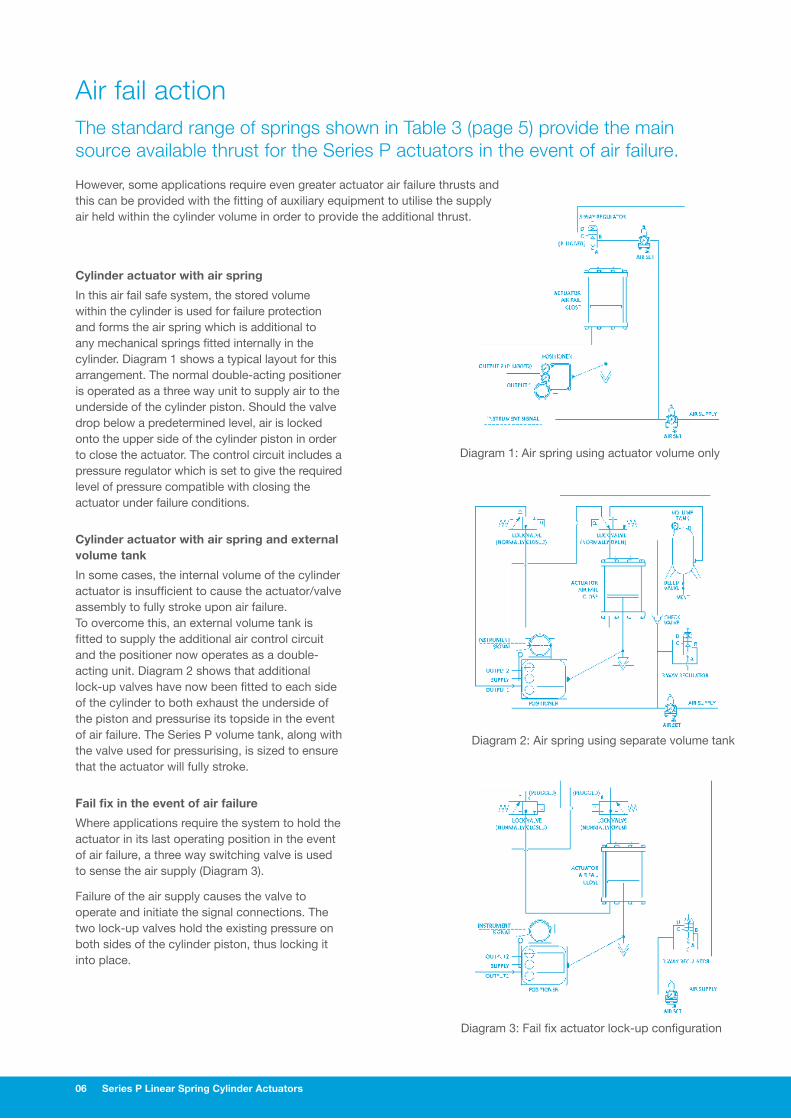
Diagram 2: Air spring using separate volume tank
Diagram 3: Fail fix actuator lock-up configuration
Diagram 1: Air spring using actuator volume only
06 Series P Linear Spring Cylinder Actuators
Air fail action The standard range of springs shown in Table 3 (page 5) provide the main source available thrust for the Series P actuators in the event of air failure.
Cylinder actuator with air spring
In this air fail safe system, the stored volume within the cylinder is used for failure protection and forms the air spring which is additional to any mechanical springs fitted internally in the cylinder. Diagram 1 shows a typical layout for this arrangement. The normal double-acting positioner is operated as a three way unit to supply air to the underside of the cylinder piston. Should the valve drop below a predetermined level, air is locked onto the upper side of the cylinder piston in order to close the actuator. The control circuit includes a pressure regulator which is set to give the required level of pressure compatible with closing the actuator under failure conditions.
Cylinder actuator with air spring and external volume tank
In some cases, the internal volume of the cylinder actuator is insufficient to cause the actuator/valve assembly to fully stroke upon air failure. To overcome this, an external volume tank is fitted to supply the additional air control circuit and the positioner now operates as a double-acting unit. Diagram 2 shows that additional lock-up valves have now been fitted to each side of the cylinder to both exhaust the underside of the piston and pressurise its topside in the event of air failure. The Series P volume tank, along with the valve used for pressurising, is sized to ensure that the actuator will fully stroke.
Fail fix in the event of air failure
Where applications require the system to hold the actuator in its last operating position in the event of air failure, a three way switching valve is used to sense the air supply (Diagram 3).
Failure of the air supply causes the valve to operate and initiate the signal connections. The two lock-up valves hold the existing pressure on both sides of the cylinder piston, thus locking it into place.
However, some applications require even greater actuator air failure thrusts and this can be provided with the fitting of auxiliary equipment to utilise the supply air held within the cylinder volume in order to provide the additional thrust.

Series P Linear Spring Cylinder Actuators 07
Improving actuator stroking speedsSeries P Linear Spring Cylinder Actuators can be fitted with volume boosters in order to improve the response times and actuator stroking speeds (for more information please see specification bulletin number (SGI-B 10).
Hand wheel operators
Two types of geared hand wheel are available for fitting to the Series P range of cylinder actuators, as follows:
1 Top mounted, continuously connected unit which is rated up to the full output thrust of the actuator.
2 Side mounted de-clutchable unit which is fitted below the actuator cylinder, leaving the top free for other accessories to be fitted. Table 6 shows the maximum output thrusts generated by these units.
Continuously connected hand wheel
Designed by Severn Glocon, this hand wheel can be used to extend, or retract the stem as well as acting as either a high, or low limit stop. A neutral position is indicated on the mechanism when the actuator is in automatic operational mode. The geared unit is sealed within a weather resistant enclosure and the ratios selected ensure a low torque input for high output thrusts.
Turning the wheel moves the screw against the locknut in order to retract the stem. Moving the wheel in a counter clockwise direction brings the lower portion of the screw into contact with the shoulder on the stem, forcing the stem to extend.
A neutral position is obtained with the handwheel screw in any position other than the indicated central neutral, providing a stop to limit travel in either direction.
De-clutchable hand wheel
Available throughout the range of actuator sizes up to 12in (300mm), the hand wheels are capable of providing forces in either direction. The gearing has been selected to ensure easy operation up to its maximum thrust capability (see Table 6 on page 8). The side mounted hand wheel unit may be fitted retrospectively if required. De-clutchable hand wheels provide the same positional accuracy as the positioning actuators. Fitted with a manual changeover valve the Series P actuator is isolated during hand wheel operation.
Positional accuracy
The de-clutchable hand wheels provide the same positional accuracy as the positioning actuators. Fitted with a manual changeover valve the Series P Actuator is isolated during hand wheel operation.
Note:
1 Model 1000 Boosters fitted to top and bottom ports of Actuator, with 1/4in fittings between cylinder and boosters, and separate 12mm diameter feed for boosters. 7bar air supply used.
2 For sizes or strokes outside these listed or faster stroke speeds please contact us.
Actuator designation With positioner * With model 1000 booster
Actuator Stroke Total time open Total time close Total time open Total time close Size in mm sec sec sec sec
25 0.75 20 <2 <2 1 1 25 4.00 100 <3 <3 <2 <2 50 1.50 40 <5 <5 <2 <2 50 4.00 100 <5 <4 3 <2 100 2.50 65 16 16 <4 <3.5 100 5.00 125 35 34 7 6.5 100 6.00 150 42 40 8 7.5 100 4.00 100 13.5 11 3 <2 200 5.00 125 65 62 15 14 200 6.00 150 75 73 15.5 14.5
Table 5: Series P Linear Spring Cylinder Actuator – Stroking speeds
* Speed depends upon positioner selected and size fittings and of pipe work. The illustration data is based on a digital positioner calibrated at 4-20mA and 7bar air supply. Linear Spring Cylinder Actuator fitted with fail close standard spring.

08 Series P Linear Spring Cylinder Actuators
Hand wheel operators
Top mounted continuously connected hand wheel and Series P Actuator
Side mounted de-clutchable hand wheel and Series P Actuator
Side mounted de-clutchable hand wheel and Series P Actuator
Actuator Hand wheel diameter Turns (in) Turning force Output thrust
Size in mm Travel lbF kgF lbF kgF
25 6 150 35 23 10 2000 910 50 8 203 45 45 20 3000 1360 100 10 254 45 46 21 5000 2270 200/5 12 305 60 50 23 7000 3180
Table 6: De-clutchable side mounted hand wheel specification

Series P Linear Spring Cylinder Actuators 09
Standard dimensions & weights
P Series dimensions Top mounted hand wheel dimensions
Side mounted hand wheel dimensions
Actuator Diameter D Length E Length M1 Length E1 Length M2 Length E2
Size in mm in mm in mm in mm in mm in mm
25 8.25 210 14.38 365 8.63 211 27.25 692 – – – – 50 10.25 260 18.62 472 9 229 31.75 806 – – – – 100-2.5 15.375 390 23.88 605 10.13 257 39.88 1013 – – – – 100-5 15.375 390 39.5 1005 – – – – 8.63 220 54.75 1390 100-6 15.375 390 40.9 1040 – – – – 8.63 220 55.71 1415 100-12 15.375 390 53 1346 – – – – 8.63 220 82 2085 200-6 20.75 527 44.30 1125 – – – – 8.63 220 59.10 1500 200-12 20.75 527 56 1425 – – – – 8.63 220 85 2160
Table 7: Dimensions
Actuator Actuator only With top mounted hand wheel With side mounted hand wheel
Size lb kg Ib kg Ib kg
25 21 9.5 49 22.2 – – 50 36 16.3 72 32.7 – – 100-2.5 85 38.6 145 65.8 – – 200-6 340 155 – – 510 232
Table 8: Weights

01 Severn Glocon Group plc Gloucester England UK
Mars Valve UK Gloucester England UK
L.B.Bentley Stroud England UK
Ionex SG Nailsworth England UK
02 Severn Unival Brighouse England UK
03 Severn Subsea Technologies Redruth England UK
04 Severn Unival Widnes England UK
05 Severn Ball Valves Aberdeen Scotland UK
06 Severn Norway Bergen Norway
07 Severn Glocon Atlantic Canada Newfoundland Canada
08 Severn Glocon Calgary Canada
09 Severn Glocon Houston Texas USA
10 Severn Glocon Rio Brazil
11 Severn Valve Solutions Basra Iraq
12 Severn Glocon Saudi Arabia
13 Severn Glocon Doha Qatar
14 QTRCO SG Dubai
15 Severn Glocon FZE Dubai
16 Severn Glocon India Chennai India
17 Severn Glocon Kuala Lumpur Malaysia
18 Severn Glocon Australia Perth Australia
19 Severn Glocon Beijing China
20 Severn Glocon Seoul Korea
21 Severn Glocon Tokyo Japan
06
01
07
09
08
10
1211
13
0204
03
05
16
17
18
19
20
1415
21
The Severn Glocon Group policy is one of continuous improvement and
we reserve the right to modify these specification details without notice. Brochure design by verycreativepeople.co.uk
PRECISION I RELIABILITY I PERFORMANCE
Olympus Park Quedgeley Gloucester Gloucestershire GL2 4NF England
T. +44 (0)845 223 2040 F. +44 (0)845 223 2041 [email protected] www.severnglocon.com