Exlar GS Series Linear Actuator Family - Olsen … · 3 Exlar GS Series Linear Actuator Family The...
34
3 Exlar GS Series Linear Actuator Family The GS Series linear actuator family offers you two grades of actuator to provide cost effective options in order to meet your application’s require- ments. View the chart below to com- pare the GSX and GSM models. All GS Series actuators use a special- ly designed roller screw mechanism for converting electric motor power into linear motion within the actuator. Planetary rollers assembled around the actu- ator’s extending rod follow threads which are precisely machined on the inside surface of the actua- tor’s hollow armature. Linear motion is produced in precise synchroniza- tion with the armature rotation. Because this roller screw mechanism has an inherently larger cumulative contact surface, these actuators have a much longer working life, and can handle heavier loads at higher speeds than is possible from a similarly sized unit built around a ball screw system. Exlar’s T-LAM segmented lamina- tion stator technology delivers higher continuous motor torque than is available in traditionally wound motors. T-LAM technology consists of stator segments, each containing individual phase wiring for maximum motor performance. The improved efficiencies of the GSX Series are a result of the limited heat generation qualities inherent in the segmented stator design as seen above. The elimination of end turns in the stator, and use of thermally conductive potting removes the parts most susceptible to failure in a tradi- tional stator. Other design advan- tages include: • Neodymium-iron-boron magnets provide high flux density and maxi- mum motor torque. • Thermally conductive potting of the entire stator provides increased heat dissipation and provides pro- tection from contamination in oil- cooled units. • Each stator segment contains indi- vidual phase wiring. External wind- ing of individual segments provides maximum slot fill for maximum motor performance. • Motors with T-LAM technology have Class 180 H insulation sys- tems compliant with UL require- ments. • UL recognized component. • Motors with T-LAM technology are CE compliant The Actuator & Motor, All in one Compact Unit. With other actuator technologies, customers are usually responsible for engineering the completed linear motion system. This usually includes purchasing the motor, gear reducer, timing belt, mounting hardware, flexi- ble couplings, etc. separately. Then they all must be assembled to per- form properly in a given application. GS Series actuators eliminate all this systems engineering. These units are single, fully inegrated component packages - much smaller than tradi- tional rotary-to-linear conversion mechanisms. Designed for Closed Loop Servo Systems Their brushless servo design means GS Series units can be used in advanced closed-loop servo systems when velocity and positioning is required. Position feedback can be delivered in a number of different firms. These include resolvers, encoders or internally mounted linear position feedback sensors. Lamination Endcaps Individual Segments GSX and GSM Differences GSX (pg 4) GSM (pg 38) Ingress Protection IP65 IP54 (IP65 optional) No. of Stacks 1, 2, 3 1, 2 Life BSY (Ball Screw Years) 15X 2 to 5X Oil Cooling Yes No Food Grade Paint Yes No Electroless Nickel Housing Yes No Stainless Steel Case Yes No Hard Coat Anodized Yes Yes LVDT FB Yes (except 2˝ frame) Yes (except 2˝ frame) 5.5 in. Frame Yes No 7 in. Frame Yes No Force (lbf) 92 - 15,000 92 - 3,966 1.0 Lead 50 & 60 only No Rear Brake all (GSX60 front brake) all Speeds (ips) 5 - 40 5 - 37.5 Electroless Nickel Connectors Yes Yes Exlar Corporation • 952.368.3434
Transcript of Exlar GS Series Linear Actuator Family - Olsen … · 3 Exlar GS Series Linear Actuator Family The...

3
Exlar GS Series Linear ActuatorFamilyThe GS Series linear actuator familyoffers you two grades of actuator toprovide cost effective options in orderto meet your application’s require-ments. View the chart below to com-pare the GSX and GSM models.
All GS Series actuators use a special-ly designed roller screw mechanismfor converting electric motor powerinto linear motion within theactuator. Planetary rollersassembled around the actu-ator’s extending rod followthreads which are preciselymachined on the insidesurface of the actua-tor’s hollowarmature.Linear motionis produced inprecise synchroniza-tion with the armaturerotation. Because thisroller screw mechanism has aninherently larger cumulative contactsurface, these actuators have a muchlonger working life, and can handleheavier loads at higher speeds thanis possible from a similarly sized unit
built around a ballscrew system.
Exlar’s T-LAM segmented lamina-tion stator technology delivershigher continuous motor torquethan is available in traditionally
wound motors. T-LAM technologyconsists of stator segments, eachcontaining individual phase wiring formaximum motor performance. Theimproved efficiencies of the GSXSeries are a result of the limited heatgeneration qualities inherent in the
segmented stator design as seenabove. The elimination of end turnsin the stator, and use of thermallyconductive potting removes the partsmost susceptible to failure in a tradi-tional stator. Other design advan-tages include:
• Neodymium-iron-boron magnetsprovide high flux density and maxi-mum motor torque.
• Thermally conductive potting of theentire stator provides increasedheat dissipation and provides pro-tection from contamination in oil-cooled units.
• Each stator segment contains indi-vidual phase wiring. External wind-ing of individual segments providesmaximum slot fill for maximummotor performance.
• Motors with T-LAM technologyhave Class 180 H insulation sys-tems compliant with UL require-ments.
• UL recognized component.• Motors with T-LAM technology are
CE compliant
The Actuator & Motor, All in oneCompact Unit.With other actuator technologies,customers are usually responsible forengineering the completed linearmotion system. This usually includespurchasing the motor, gear reducer,timing belt, mounting hardware, flexi-ble couplings, etc. separately. Thenthey all must be assembled to per-form properly in a given application.
GS Series actuators eliminate all thissystems engineering. These unitsare single, fully inegrated componentpackages - much smaller than tradi-tional rotary-to-linear conversionmechanisms.
Designed for Closed Loop ServoSystemsTheir brushless servo design meansGS Series units can be used inadvanced closed-loop servo systemswhen velocity and positioning isrequired. Position feedback can bedelivered in a number of differentfirms. These include resolvers,encoders or internally mounted linearposition feedback sensors.
LaminationEndcaps
IndividualSegments
GSX and GSM Differences GSX (pg 4) GSM (pg 38)Ingress Protection IP65 IP54 (IP65 optional)No. of Stacks 1, 2, 3 1, 2Life BSY (Ball Screw Years) 15X 2 to 5XOil Cooling Yes NoFood Grade Paint Yes NoElectroless Nickel Housing Yes NoStainless Steel Case Yes NoHard Coat Anodized Yes YesLVDT FB Yes (except 2˝ frame) Yes (except 2˝ frame)5.5 in. Frame Yes No7 in. Frame Yes NoForce (lbf) 92 - 15,000 92 - 3,9661.0 Lead 50 & 60 only NoRear Brake all (GSX60 front brake) allSpeeds (ips) 5 - 40 5 - 37.5Electroless Nickel Connectors Yes Yes
Exlar Corporation • 952.368.3434

4
GSX
Serie
s
Exlar GSX Series The HighestPerfomance and Longest LifeSolutionFor applications that require long lifeand contiuous duty, even in harshenvironments the GSX Series actua-tor offers a robust solution. Thelife of the GSX Series canexceed that of a ball screwactuator by 15X whiledelivering high speeds andhigh forces. This compact packagehas all the advantages that ourGS Series offers.
Sealed for Long Life withMinimum MaintenanceGSX Series actuators have strongadvantages whenever outside contami-nants are an issue. In most rotary-to-linear devices, critical mechanisms areexposed to the environment. Thus,they must be frequently inspected,cleaned and lubricated.
In contrast, the converting componentsin all Exlar GSX units are mountedwithin the sealed motor housing. Witha simple bushing and seal arrangementon the smooth extending rod, abrasiveparticles or other contaminants areprevented from reaching the actuator’scritical mechanisms. This assurestrouble-free operation even in the mostharsh environments.
Lubrication requirements are minimal.GSX actuators can be lubricated witheither grease or recirculated oil.Grease lubricated units will run up to10,000 hours without re-greasing.Recirculated oil systems eliminate thistype of maintenance altogether. A GSXSeries actuator with a properly operat-ing recirculating oil system will operateindefinitely without any other lubrica-tion requirements.
Available in Five Frame Sizes2” GSX20 3” GSX30 4” GSX405” GSX50 7” GSX60
Feature Standard OptionalExternal anti-rotate No Yesmechanism
Pre-loaded follower No Yes
Electric brake No Yes
External End switches No Yes
Two MS Style Electroless NickelConnectors Connectors Connectors/Male NPT
(3 if brake is Ordered) with Potted Leads/Manufacturers Connectors
Extended Tie Rods, SideMounting Style Tapped Mounting Holes, Custom
Trunnion, Rear Clevis, or MountingsFront Flange
Rod End Male or Female: Specials Available ToU.S. Standard or Metric Meet OEM Requirements
Greased, Oil ConnectionLubrication Ports are Built-in for Specials Available To
Customer Supplied Meet OEM RequirementsRecirculated Oil Lubrication
Standard Encoders orPrimary Feedback Resolvers to Meet Most Custom Feedback
Amplifier Requirements
Absolute Linear No VRVT, including Feedback signal conditioner
If you need a custom design, Exlar’sApplication Engineering department willwork with you to engineer a solutionspecifically tailored to yourapplication.
952.368.3434 • Exlar Corporation

Hydraulic cylinder replacementBall screw replacementPneumatic cylinder replacementChip and wafer handlingAutomated flexible fixturingDispensersMachine toolAutomated assemblyParts clampingAutomatic tool changersVolumetric pumpsMedical equipment
Exlar GSX Series Linear Actuators Applications Include:
Conveyor diverters / gatesPlastics equipmentCut-offsDie cuttersPackaging machineryEntertainmentSawmill equipmentOpen / close doorsFillersFormersPrecision grinders
Indexing stagesLiftsProduct sortingMaterial cuttingMaterial handlingRiveting / fastening / joiningMoldingVolumetric pumpsSemiconductorPick and place systemsRobot manipulator arms
SimulatorsPrecision valve controlVentilation control systemsPressingProcess controlTube bendingWeldingStampingTest standsTension controlWeb guidanceWire winding
5
In clean roomapplications like thosecommon to semiconductormanufacturing, the compactdesign of our GSX Series savescritical space.
Because theycycle quickly and
can be synchronized to line speeds,Exlar actuators produce dramatic
improvements in web control applica-tions.
Repeatable force, reliable posi-tioning accuracy, and flexible con-trol make GSX actuators aperfect fit for assem-bly presses ortest stands.
Repeatable force control plus positioningaccuracy extends the life of costly toolswhen Exlar linear actuators are used inprecision clamping applications.
Exlar Corporation • 952.368.3434

6
1X82X8
200018001600140012001000800600400200
00 1 2 3 4 5 6
Fo
rce
(lb
f)
Speed (inch / sec)
GSX30-.1 Inch Lead1X82X8
700
600
500
400
300
200
100
00 1 2 3 4 5 6 7 8 9
Fo
rce
(lb
f)
Speed (inch / sec)
GSX20-.1 Inch Lead
1X82X83X8
400
350
300
250
200
150
100
50
00 2 4 6 8 10 12 14 16 18
Fo
rce
(lb
f)
Speed (inch / sec)
GSX20-.2 Inch Lead
1X82X83X8
200
150
100
50
00 5 10 15 20 25 30 35
Fo
rce
(lb
f)
Speed (inch / sec)
GSX20-.4 Inch Lead
1X82X83X8
1000900800700600500400300200100
00 2 4 6 8 10 12
Fo
rce
(lb
f)
Speed (inch / sec)
GSX30-.2 Inch Lead
1X82X83X8
450
400
350
300
250
200
150
100
50
00 5 10 15 20 25 30
Fo
rce
(lb
f)
Speed (inch / sec)
GSX30-.5 Inch Lead
Test data derived using NEMA recommended aluminum heatsink 10˝ x 10˝ x 1/4˝ for GSX20 and 10˝ x 10˝ x 3/8˝ for GSX30
GSX
Serie
s
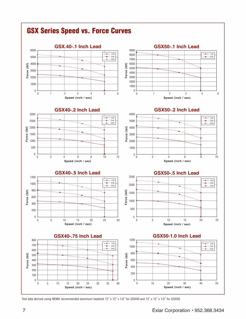
GSX Series Speed vs. Force CurvesThese charts represent typical linear speed versus linear force curves for the GSX actuators usingcommon brushless motor amplifiers. The GSX Series are compatible with many different brushlessmotor amplifiers, and differences in the performance ratings of these amplifiers can alter the actua-tor’s performance. Thus, the curves below should be used for estimation only. (Further informationis available by contacting Exlar Application Engineering.)
952.368.3434 • Exlar Corporation
7
1X82X8
9000
8000
7000
6000
5000
4000
3000
2000
1000
00 1 2 3 4 6
Fo
rce
(lb
f)
Speed (inch / sec)
GSX50-.1 Inch Lead
1X82X83X8
6000
5000
4000
3000
2000
1000
00 2 4 6 8 10
Fo
rce
(lb
f)
Speed (inch / sec)
GSX50-.2 Inch Lead
1X82X83X8
2500
2000
1500
1000
500
00 5 10 15 20 25
Fo
rce
(lb
f)
Speed (inch / sec)
GSX50-.5 Inch Lead
1X82X83X8
1200
1000
800
600
400
200
00 10 20 30 40 50
Fo
rce
(lb
f)
Speed (inch / sec)
GSX50-1.0 Inch Lead
1X82X83X8
6000
5000
4000
3000
2000
1000
00 1 2 3 4 5 6
Fo
rce
(lb
f)
Speed (inch / sec)
GSX.40-.1 Inch Lead
1X82X83X8
800
700
600
500
400
300
200
100
00 5 10 15 20 25 30 35 40
Fo
rce
(lb
f)
Speed (inch / sec)
GSX40-.75 Inch Lead
1X82X83X8
3000
2500
2000
1500
1000
500
00 2 4 6 8 10 12
Fo
rce
(lb
f)
Speed (inch / sec)
GSX40-.2 Inch Lead
1X82X83X8
1200
1000
800
600
400
200
00 5 10 15 20 25 30
Fo
rce
(lb
f)
Speed (inch / sec)
GSX40-.5 Inch Lead
Test data derived using NEMA recommended aluminum heatsink 12˝ x 12˝ x 1/2˝ for GSX40 and 12˝ x 12˝ x 1/2˝ for GSX50
GSX Series Speed vs. Force Curves
Exlar Corporation • 952.368.3434

8
Speed (inch / sec)
These charts represent typical linear speed versus lin-ear force curves for GSX actuators using commonbrushless motor amplifiers. The GSX Series arecompatible with many different brushless motoramplifiers, and differences in the performance ratingsof these amplifiers can alter the actuator’s perform-ance. Thus, the curves below should be used forestimation only. (Further information is available bycontacting Exlar Application Engineering.)
1X82X83X8
14000
12000
10000
8000
6000
4000
2000
00 2 4 6 8 10 12
Fo
rce
(lb
f)
Speed (inch / sec)
GSX60-.25 Inch Lead
1X82X83X8
7000
6000
5000
4000
3000
2000
1000
00 5 10 15 20 25
Fo
rce
(lb
f)
Speed (inch / sec)
GSX60-.5 Inch Lead
1X82X83X8
3500
3000
2500
2000
1500
1000
500
00 10 20 30 40 50
Fo
rce
(lb
f)
GSX60-1.0 Inch Lead
Test data derived using NEMA recommended aluminum heatsink 16˝ x 16˝ x 1˝ for GSX60
GSX
Serie
s
952.368.3434 • Exlar Corporation

GSX60-xx03GSX60-xx05GSX60-xx10
GSX Series Lifetime CurvesThe L10 expected life of a roller screw linear actuator is expressed as the linear travel distance that 90% of properly maintained roller screws manufactured areexpected to meet or exceed. This is not a guarantee and these charts should be used for estimation purposes only.The underlying formula that defines this value is:
Travel life in millions of inches, where:C = Dynamic load rating (lbf)F = Cubic mean applied load (lbf)S = Roller screws lead (inches)
L10 = ( C )3x S ≡
FAll curves represent properly lubricated and maintained actuators.
GSX50-xx01GSX50-xx02GSX50-xx05GSX50-xx10xx
x
x
xx
x x x x x
GSX40-xx01GSX40-xx02GSX40-xx05GSX40-xx08x
xx x
x x
x
xx
x
x
400
350
300
250
200
150
100
50
0
GSX20
Me
an
Lo
ad
(p
ou
nd
s)
10 100 1,000 10,000 100,000Travel Life (Millions of inches)
2,000
1,800
1,600
1,400
1,200
1,000
800
600
400
200
010 100 1,000 10,000 100,000
Me
an
Lo
ad
(p
ou
nd
s)
Travel Life (Millions of inches)
GSX30
9,000
8,000
7,000
6,000
5.000
4,000
3,000
2,000
1,000
01 10 100 1,000 10,000 100,000
Me
an
Lo
ad
(p
ou
nd
s)
Travel Life (Millions of inches)
GSX50
12,000
10,000
8,000
6,000
4,000
2,000
01 10 100 1,000 10,000 100,000
Me
an
Lo
ad
(p
ou
nd
s)
Travel Life (Millions of inches)
GSX60
4,000
3,500
3,000
2,500
2,000
1,500
1,000
500
0
1 10 100 1,000 10,000 100,000
Me
an
Lo
ad
(p
ou
nd
s)
Travel Life (Millions of inches)
GSX40
9 Exlar Corporation • 952.368.3434

GSX20 & GSX30 Performance Specifications
Model Frame Stroke Screw Continuous Max Continuous Maximum Armature Dynamic WeightSize (nominal)* Lead Force Rating Velocity Motor Static Inertia** Load (approx.)
in in in lb (N) in/sec Torque Load lb-in-s2 Rating lb (mm) (mm) (mm) 1/2/3 stack (mm/sec) lb-in (N-m) lb (N) (Kg-m2) lb (N) (Kg)
GSX20-0301 2.25 3 0.1 367/578/NA 8.33 7.3/11.5/NA 1250 0.00101 2075 6.5(57) (75) (2.54) (1632/2571/NA) (211.67) (0.82/1.30/NA) (5560) (0.000114) (9230) (2.9)
GSX20-0302 2.25 3 0.2 183/289/NA 16.77 7.3/11.5/NA 1250 0.00101 1540 6.5(57) (75) (5.08) (814/1286/NA) (423.33) (0.82/1.30/NA) (5560) (0.000114) (6850) (2.9)
GSX20-0304 2.25 3 0.4 92/145/NA 33.33 7.3/11.5/NA 1250 0.00101 1230 6.5(57) (75) (10.16) (409/645/NA) (846.67) (0.82/1.30/NA) (5560) (0.000114) (5471) (2.9)
GSX20-0601 2.25 6 0.1 367/578/NA 8.33 7.3/11.5/NA 1250 0.00114 2075 8.0(57) (150) (2.54) (1632/2571/NA) (211.67) (0.82/1.30/NA) (5560) (0.000129) (9230) (3.6)
GSX20-0602 2.25 6 0.2 183/289/385 16.67 7.3/11.5/15.3 1250 0.00114 1540 8.0(57) (150) (5.08) (814/1286/1713) (423.33) (0.82/1.30/1.73) (5560) (0.000129) (6850) (3.6)
GSX20-0604 2.25 6 0.4 92/145/192 33.33 7.3/11.5/15.3 1250 0.00114 1230 8.0(57) (150) (10.16) (409/645/854) (846.67) (0.82/1.30/1.73) (5560) (0.000129) (5471) (3.6)
GSX20-1001 2.25 10 0.1 367/578/NA 8.33 7.3/11.5/NA 1250 0.00133 2075 9.5(57) (250) (2.54) (1632/2571/NA) (211.67) (0.82/1.30/NA) (5560) (0.000150) (9230) (4.3)
GSX20-1002 2.25 10 0.2 183/289/385 16.67 7.3/11.5/15.3 1250 0.00133 1540 9.5(57) (250) (5.08) (814/1286/1713) (423.33) (0.82/1.30/1.73) (5560) (0.000150) (6850) (4.3)
GSX20-1004 2.25 10 0.4 92/145/192 33.33 7.3/11.5/15.3 1250 0.00133 1230 9.5(57) (250) (10.16) (409/645/854) (846.67) (0.82/1.30/1.73) (5560) (0.000150) (5471) (4.3)
GSX20-1201 2.25 12 0.1 367/578/NA 8.33 7.3/11.5/NA 1250 0.00143 2075 11.0(57) (300) (2.54) (1632/2571/NA) (211.67) (0.82/1.30/NA) (5560) (0.000162) (9230) (4.9)
GSX20-1202 2.25 12 0.2 183/289/385 16.67 7.3/11.5/15.3 1250 0.00143 1540 11.0(57) (300) (5.08) (814/1286/1713) (423.33) (0.82/1.30/1.73) (5560) (0.000162) (6850) (4.9)
GSX20-1204 2.25 12 0.4 92/145/192 33.33 7.3/11.5/15.3 1250 0.00143 1230 11.0(57) (300) (10.16) (409/645/854) (846.67) (0.82/1.30/1.73) (5560) (0.000162) (5471) (4.9)
GSX30-0301 3.125 3 0.1 829/1347/NA 5 16.5/26.8/NA 2700 0.00319 5516 9.5(79) (75) (2.54) (3688/5992/NA) (127) (1.86/3.03/NA) (12010) (0.000360) (24536) (4.3)
GSX30-0302 3.125 3 0.2 415/674/NA 10 16.5/26.8/NA 2700 0.00319 5800 9.5(79) (75) (5.08) (1846/2998/NA) (254) (1.86/3.03/NA) (12010) (0.000360) (25798) (4.3)
GSX30-0305 3.125 3 0.5 166/269/NA 25 16.5/26.8/NA 2700 0.00319 4900 9.5(79) (75) (12.7) (738/1197/NA) (635) (1.86/3.03/NA) (12010) (0.000360) (21795) (4.3)
GSX30-0601 3.125 5.9 0.1 829/1347/NA 5 16.5/26.8/NA 2700 0.00361 5516 11.5(79) (150) (2.54) (3688/5992/NA) (127) (1.86/3.03/NA (12010) (0.000408) (24536) (5.2)
GSX30-0602 3.125 5.9 0.2 415/674/905 10 16.5/26.8/36 2700 0.00361 5800 11.5(79) (150) (5.08) (1846/2998/4026) (254) (1.86/3.03/4.07) (12010) (0.000408) (25798) (5.2)
GSX30-0605 3.125 5.9 0.5 166/269/362 25 16.5/26.8/36 2700 0.00361 4900 11.5(79) (150) (12.7) (738/1197/1610) (635) (1.86/3.03/4.07) (12010) (0.000408) (21795) (5.2)
GSX30-1001 3.125 10 0.1 829/1347/NA 5 16.5/26.8/NA 2700 0.00416 5516 19(79) (250) (2.54) (3688/5992/NA) (127) (1.86/3.03/NA) (12010) (0.00047) (24536) (8.6)
GSX30-1002 3.125 10 0.2 415/674/905 10 16.5/26.8/36 2700 0.00416 5800 19(79) (250) (5.08) (1846/2998/4026) (254) (1.86/3.03/4.07) (12010) (0.00047) (25798) (8.6)
GSX30-1005 3.125 10 0.5 166/269/362 25 16.5/26.8/36 2700 0.00416 4900 19(79) (250) (12.7) (738/1197/1610) (635) (1.86/3.03/4.07) (12010) (0.00047) (21795) (8.6)
GSX30-1201 3.125 12 0.1 829/1347/NA 5 16.5/26.8/NA 2700 0.00443 5516 20.5(79) (305) (2.54) (3688/5992/NA) (127) (1.86/3.03/NA) (12010) (0.000501) (24536) (9.3)
GSX30-1202 3.125 12 0.2 415/674/905 10 16.5/26.8/36 2700 0.00443 5800 20.5(79) (305) (5.08) (1846/2998/4026) (254) (1.86/3.03/4.07) (12010) (0.000501) (25798) (9.3)
GSX30-1205 3.125 12 0.5 166/269/362 25 16.5/26.8/36 2700 0.00443 4900 20.5(79) (305) (12.7) (738/1197/1610) (635) (1.86/3.03/4.07) (12010) (0.000501) (21795) (9.3)
GSX30-1402 3.125 14 0.2 415/674/905 10 16.5/26.8/36 2700 0.00473 5800 20.5(79) (355) (5.08) (1846/2998/4026) (254) (1.86/3.03/4.07) (12010) (0.000534) (25798) (9.3)
GSX30-1405 3.125 14 0.5 166/269/362 25 16.5/26.8/36 2700 0.00473 4900 20.5(79) (355) (12.7) (738/1197/1610) (635) (1.86/3.03/4.07) (12010) (0.000534) (21795) (9.3)
GSX30-1802 3.125 18 0.2 415/674/905 10 16.5/26.8/36 2700 0.00533 5800 25(79) (455) (5.08) (1846/2998/4026) (254) (1.86/3.03/4.07) (12010) (0.000602) (25798) (11.3)
GSX30-1805 3.125 18 0.5 166/269/362 25 16.5/26.8/36 2700 0.00533 4900 25(79) (455) (12.7) (738/1197/1610) (635) (1.86/3.03/4.07) (12010) (0.000602) (21795) (11.3)
Specifications subject to change without notice.*Please note that stroke mm are nominal dimensions. **Inertia +/– 5% See page 12 for definition of terms.
10
GSX
Serie
s
952.368.3434 • Exlar Corporation

11
GSX40 Performance Specifications
*Please note that stroke mm are nominal dimensions. **Inertia +/– 5%See page 12 for definition of terms.
Specifications subject to change without notice.
Model Frame Stroke Screw Continuous Max Continuous Maximum Armature Dynamic WeightSize (nominal)* Lead Force Rating Velocity Motor Static Inertia** Load (approx.)
in in in lb (N) in/sec Torque Load lb-in-s2 Rating lb (mm) (mm) (mm) 1/2/3 stack (mm/sec) lb-in (N-m) lb (N) (Kg-m2) lb (N) (Kg)
GSX40-0601 3.9 6 0.1 2393/3966/NA 5 47.6/78.9/NA 5400 0.0152 7900 20(99) (150) (2.54) (10645/17642/NA) (127) (5.38/8.91/NA) (24020) (0.001717) (35141) (9.1)
GSX40-0602 3.9 6 0.2 1196/1983/NA 10 47.6/78.9/NA 5400 0.0152 8300 20(99) (150) (5.08) (5320/8821/NA) (254) (5.38/8.91/NA) (24020) ( 0.001717) (36920) (9.1)
GSX40-0605 3.9 6 0.5 479/793/NA 25 47.6/78.9/NA 5400 0.0152 7030 20(99) (150) (12.7) (2131/3527/NA) (635) (5.38/8.91/NA) (24020) ( 0.001717) (31271) (9.1)
GSX40-0608 3.9 6 0.75 319/529/NA 37.5 47.6/78.9/NA 5400 0.0152 6335 20(99) (150) (19.05) (1419/2353/NA) (953) (5.38/8.91/NA) (24020) ( 0.001717) (28179) (9.1)
GSX40-0801 3.9 8 0.1 2393/3966/NA 5 47.6/78.9/NA 5400 0.0163 7900 24(99) (200) (2.54) (10645/17642/NA) (127) (5.38/8.91/NA) (24020) (0.001842) (35141) (10.9)
GSX40-0802 3.9 8 0.2 1196/1983/2692 10 47.6/78.9/107.1 5400 0.0163 8300 24(99) (200) (5.08) (5320/8821/11975) (254) (5.38/8.91/12.1) (24020) ( 0.001842) (36920) (10.9)
GSX40-0805 3.9 8 0.5 479/793/1077 25 47.6/78.9/107.1 5400 0.0163 7030 24(99) (200) (12.7) (2131/3527/4791) (635) (5.38/8.91/12.1) (24020) ( 0.001842) (31271) (10.9)
GSX40-0808 3.9 8 0.75 319/529/718 37.5 47.6/78.9/107.1 5400 0.0163 6335 24(99) (200) (19.05) (1419/2353/3194) (953) (5.38/8.91/12.1) (24020) ( 0.001842) (28179) (10.9)
GSX40-1001 3.9 10 0.1 2393/3966/NA 5 47.6/78.9/NA 5400 0.0175 7900 28(99) (250) (2.54) (10645/17642/NA) (127) (5.38/8.91/NA) (24020) (0.001977) (35141) (12.7)
GSX40-1002 3.9 10 0.2 1196/1983/2692 10 47.6/78.9/107.1 5400 0.0175 8300 28(99) (250) (5.08) (5320/8821/11975) (254) (5.38/8.91/12.1) (24020) (0.001977) (36920) (12.7)
GSX40-1005 3.9 10 0.5 479/793/1077 25 47.6/78.9/107.1 5400 0.0175 7030 28(99) (250) (12.7) (2131/3527/4791) (635) (5.38/8.91/12.1) (24020) (0.001977) (31271) (12.7)
GSX40-1008 3.9 10 0.75 319/529/718 37.5 47.6/78.9/107.1 5400 0.0175 6335 28(99) (250) (19.05) (1419/2353/3194) (953) (5.38/8.91/12.1) (24020) (0.001977) (28179) (12.7)
GSX40-1201 3.9 12 0.1 2393/3966/NA 5 47.6/78.9/NA 5400 0.0186 7900 32(99) (305) (2.54) (10645/17642/NA) (127) (5.38/8.91/NA) (24020) (0.002102) (35141) (14.5)
GSX40-1202 3.9 12 0.2 1196/1983/2692 10 47.6/8.9/107.1 5400 0.0186 8300 32(99) (305) (5.08) (5320/8821/11975) (254) (5.38/8.91/12.1) (24020) ( 0.002102) (36920) (14.5)
GSX40-1205 3.9 12 0.5 479/793/1077 25 47.6/8.9/107.1 5400 0.0186 7030 32(99) (305) (12.7) (2131/3527/4791) (635) (5.38/8.91/12.1) (24020) ( 0.002102) (31271) (14.5)
GSX40-1208 3.9 12 0.75 319/529/718 37.5 47.6/78.9/107.1 5400 0.0186 6335 32(99) (305) (19.05) (1419/2353/3194) (953) (5.38/8.91/12.1) (24020) ( 0.002102) (28179) (14.5)
GSX40-1802 3.9 18 0.2 1196/1983/2692 10 47.6/78.9/107.1 5400 0.0220 8300 44(99) (455) (5.08) (5320/8821/11975) (254) (5.38/8.91/12.1) (24020) (0.002486) (36920) (20)
GSX40-1805 3.9 18 0.5 479/793/1077 25 47.6/78.9/107.1 5400 0.0220 7030 44(99) (455) (12.7) (2131/3527/4791) (635) (5.38/8.91/12.1) (24020) (0.002486) (31271) (20)
Exlar Corporation • 952.368.3434
12
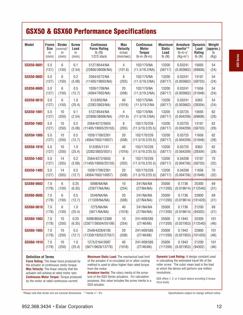
GSX50 & GSX60 Performance Specifications
Specifications subject to change without notice.
Definition of TermsForce Rating: The linear force produced bythe actuator at continuous motor torque.Max Velocity: The linear velocity that theactuator will achieve at rated motor rpm.Continuous Motor Torque: Torque producedby the motor at rated continuous current.
Maximum Static Load: The mechanical load limitof the actuator if re-circulated oil or other coolingmethod is used to allow higher than rated torquefrom the motor. Armature Inertia: The rotary inertia of the arma-ture of the GSX Series actuators. For calculationpurposes, this value includes the screw inertia in aGSX actuator.
Dynamic Load Rating: A design constant usedin calculating the estimated travel life of theroller screw. The cubic mean load is the loadat which the device will perform one millionrevolutions.
GSX offers 1, 2, or 3 stack stators providing 3 torqueforce levels.
*Please note that stroke mm are nominal dimensions. **Inertia +/– 5%
Model Frame Stroke Screw Continuous Max Continuous Maximum Armature Dynamic WeightSize (nominal)* Lead Force Rating Velocity Motor Static Inertia** Load (approx.)
in in in lb (N) in/sec Torque Load lb-in-s2 Rating lb (mm) (mm) (mm) 1/2/3 stack (mm/sec) lb-in (N-m) lb (N) (Kg-m2) lb (N) (Kg)
GSX50-0601 5.0 6 0.1 5127/8544/NA 4 102/170/NA 13200 0.03241 15693 54(127) (150) (2.54) (22806/38006/NA) (101.6) (11.5/19.2/NA) (58717) (0.003662) (69806) (24)
GSX50-0602 5.0 6 0.2 2564/4272/NA 8 102/170/NA 13200 0.03241 13197 54(127) (150) (5.08) (11405/19003/NA) (203) (11.5/19.2/NA) (58717) (0.003662) (58703) (24)
GSX50-0605 5.0 6 0.5 1026/1709/NA 20 102/170/NA 13200 0.03241 11656 54(127) (150) (12.7) (4564/7602/NA) (508) (11.5/19.2/NA) (58717) (0.003662) (51848) (24)
GSX50-0610 5.0 6 1.0 513/855/NA 40 102/170/NA 13200 0.03241 6363 54(127) (150) (25.4) (2282/3803/NA) (1016) (11.5/19.2/NA (58717) (0.003662) (28304) (24)
GSX50-1001 5.0 10 0.1 5127/8544/NA 4 102/170/NA 13200 0.03725 15693 62(127) (250) (2.54) (22806/38006/NA) (101.6) (11.5/19.2/NA) (58717) (0.004209) (69806) (28)
GSX50-1002 5.0 10 0.2 2564/4272/5655 8 102/170/226 13200 0.03725 13197 62(127) (250) (5.08) (11405/19003/25155) (203) (11.5/19.2/25.5) (58717) (0.004209) (58703) (28)
GSX50-1005 5.0 10 0.5 1026/1709/2261 20 102/170/226 13200 0.03725 11656 62(127) (250) (12.7) (4564/7602/10057) (508) (11.5/19.2/25.5) (58717) (0.004209) (51848) (28)
GSX50-1010 5.0 10 1.0 513/855/1131 40 102/170/226 13200 0.03725 6363 62(127) (250) (25.4) (2282/3803/5031) (1016) (11.5/19.2/25.5) (58717) (0.004209) (28304) (28)
GSX50-1402 5.0 14 0.2 2564/4272/5655 8 102/170/226 13200 0.04208 13197 70(127) (355) (5.08) (11405/19003/25155) (203) (11.5/19.2/25.5) (58717) (0.004756) (58703) (32)
GSX50-1405 5.0 14 0.5 1026/1709/2261 20 102/170/226 13200 0.04208 11656 70(127) (355) (12.7) (4564/7602/10057) (508) (11.5/19.2/25.5) (58717) (0.004756) (51848) (32)
GSX60-0603 7.0 6 0.25 5098/NA/NA 10 241/NA/NA 25000 0.1736 25300 69(178) (150) (6.35) (22677/NA/NA) (254) (27/NA/NA) (111200) (0.019614) (112540) (31)
GSX60-0605 7.0 6 0.5 2549/NA/NA 20 241/NA/NA 25000 0.1736 22800 69(178) (150) (12.7) (11339/NA/NA) (508) (27/NA/NA) (111200) (0.019614) (101420) (31)
GSX60-0610 7.0 6 1.0 1275/NA/NA 40 241/NA/NA 25000 0.1736 21200 69(178) (150) (25.4) (5671/NA/NA) (1018) (27/NA/NA) (111200) (0.019614) (94302) (31)
GSX60-1003 7.0 10 0.25 5098/8656/12389 10 241/409/585 25000 0.1943 25300 101(178) (250) (6.35) (22677/38504/55109) (254) (27/46/66) (111200) (0.021953) (112540) (46)
GSX60-1005 7.0 10 0.5 2549/4328/6195 20 241/409/585 25000 0.1943 22800 101(178) (250) (12.7) (11339/19252/27557) (508) (27/46/66) (111200) (0.021953) (101420) (46)
GSX60-1010 7.0 10 1.0 1275/2164/3097 40 241/409/585 25000 0.1943 21200 101(178) (250) (25.4) (5671/9626/13776) (1018) (27/46/66) (111200) (0.021953) (94302) (46)
GSX
Serie
s
952.368.3434 • Exlar Corporation

13
GSX20 Mechanical and Electrical Specifications
Specifications subject to change without notice.
GSX20Nominal Backlash in (mm) 0.004 (.10)Maximum Backlash (pre-loaded) in (mm) 0.0Lead Accuracy in/ft (mm/300 mm) 0.001 (.025)Maximum Radial Load lb (N) 20 (90)Environmental Rating: Standard / Optional IP65Motor Stator 118 138 158 168 218 238 258 268 318* 338* 358* 368*RMS Sinusoidal Commutation Continuous Motor Torque lbf-in 7.6 7.3 7.0 7.0 11.9 11.5 11.2 11.3 15.3 15.3 14.8 15.0
(Nm) (0.86) (0.83) (0.79) (0.79) (1.35) (1.30) (1.27) (1.28) (1.73) (1.73) (1.67) (1.69)Torque Constant (Kt) lbf-in/A 2.5 5.2 8.3 9.5 2.5 5.2 8.9 10.2 2.3 5.3 8.8 10.2(+/– 10% @ 25˚C) (Nm/A) (0.28) (0.59) (0.94) (1.07) (0.28) (0.59) (1.00) (1.15) (0.26) (0.60) (0.99) (1.15)Continuous Current Rating: Greased (IG) A 3.4 1.6 0.9 0.8 5.4 2.5 1.4 1.2 7.3 3.2 1.9 1.6
Oiled (IL) A 6.9 3.1 1.9 1.6 10.8 4.9 2.8 2.5 14.6 6.5 3.8 3.3Peak Current Rating Amps 6.9 3.1 1.9 1.6 10.8 4.9 2.8 2.5 14.6 6.5 3.8 3.3Trapezoidal Commutation Continuous Motor Torque lbf-in 7.3 7.0 6.7 6.7 11.4 11.0 10.7 10.8 14.7 14.6 14.1 14.3
(Nm) (0.82) (0.79) (0.76) (0.76) (1.29) (1.24) (1.21) (1.22) (1.66) (1.65) (1.60) (1.61)Torque Constant (Kt) lbf-in/A 1.9 4.1 6.5 7.4 1.9 4.1 6.9 7.9 1.8 4.1 6.9 7.9(+/– 10% @ 25˚C) (Nm/A) (0.22) (0.46) (0.73) (0.84) (0.22) (0.46) (0.78) (0.89) (0.21) (0.46) (0.77) (0.89)Continuous Current Rating: Greased (IG) A 4.2 1.9 1.1 1.0 6.6 3.0 1.7 1.5 9.0 4.0 2.3 2.0
Oiled (IL) A 8.4 3.9 2.3 2.0 13.2 6.0 3.5 3.0 17.9 8.0 4.6 4.0Peak Current Rating Amps 8.4 3.9 2.3 2.0 13.2 6.0 3.5 3.0 17.9 8.0 4.6 4.0Motor Stator DataVoltage Constant (Ke) Vrms/krpm 16.9 35.6 56.9 64.9 16.9 35.6 60.5 69.4 16.0 36.0 60.0 69.4(+/– 10% @ 25˚C) Vpk/kprm 23.9 50.3 80.5 91.8 23.9 50.3 85.5 98.1 22.6 50.9 84.9 98.1Pole Configuration 8 8 8 8 8 8 8 8 8 8 8 8 8Resistance (L-L) (+/– 5% @ 25˚C) Ohms 2.6 12.5 35.2 45.8 1.1 5.3 16.0 20.7 0.62 3.1 9.4 12.2Inductance (L-L)(+/– 15%) mH 5.1 22.8 58.3 75.8 2.5 11.0 31.7 41.7 1.5 7.4 20.5 27.4Brake Inertia lbf-in-sec2 0.00012
(Kg-cm2) (0.135)Brake Current @ 24 Vdc A 0.33Brake Holding Torque lbf-in 19
(Nm) (2.2)Brake Engage/Disengage Time ms 14/28Mechanical Time Constant (tm),ms min 6.0 6.5 7.1 7.1 2.5 2.7 2.9 2.8 1.6 1.6 1.7 1.7
max 8.5 9.2 10.1 10.1 3.6 3.9 4.0 4.0 2.2 2.2 2.4 2.4Electrical Time Constant (te) ms 2.0 1.8 1.7 1.7 2.2 2.1 2.0 2.0 2.4 2.4 2.2 2.2Damping Constant lbf-in/krpm 0.55 0.55 0.55 0.55 0.55 0.55 0.55 0.55 0.55 0.55 0.55 0.55
(Nm/krpm) (0.06) (0.06) (0.06) (0.06) (0.06) (0.06) (0.06) (0.06) (0.06) (0.06) (0.06) (0.06)Friction Torque lbf-in 1.00 1.00 1.00 1.00 1.00 1.00 1.00 1.00 1.00 1.00 1.00 1.00
(Nm) (0.11) (0.11) (0.11) (0.11) (0.11) (0.11) (0.11) (0.11) (0.11) (0.11) (0.11) (0.11)Bus Voltage Vrms 115 230 400 460 115 230 400 460 115 230 400 460Speed @ Bus Voltage rpm 5000 5000 5000 5000 5000 5000 5000 5000 5000 5000 5000 5000Motor Wire Insulation Class 180 HMotor Stator Rating Class 180 HThermal Switch Case Temperature ˚C 100Standard Connectors (O-option) Motor MS-3112-E16-8P
Feedback MS-3112-E14-18PBrake MS-3112-E12-8P
All ratings at 25 degrees CelsiusFor amplifiers using peak sinusoidal ratings, multiply RMS sinusoidal Kt by .707 and current by 1.414.*Refer to performance specifications on page 10 and 11 for availability of 3 stack stator by stroke/lead combination.Test data derived using NEMA recommended aluminum heatsink 10˝ x 10˝ x 1/4˝
Exlar Corporation • 952.368.3434

14
GSX30 Mechanical and Electrical Specifications
Specifications subject to change without notice.
GSX
Serie
s
GSX30Nominal Backlash in (mm) 0.004 (.10)Maximum Backlash (pre-loaded) in (mm) 0.0Lead Accuracy in/ft (mm/300 mm) 0.001 (.025)Maximum Radial Load lb (N) 30 (134)Environmental Rating: Standard / Optional IP65Motor Stator 118 138 158 168 218 238 258 268 318* 338* 358** 368*RMS Sinusoidal Commutation Continuous Motor Torque lbf-in 16.6 16.5 15.7 15.7 26.8 26.8 26.7 26.7 38.7 38.3 36.3 36.3
(Nm) (1.88) (1.87) (1.77) (1.78) (3.03) (3.03) (3.02) (3.01) (4.38) (4.33) (4.10) (4.10)Torque Constant (Kt) lbf-in/A 4.4 8.7 15.5 17.5 4.4 8.7 15.5 17.5 4.4 8.7 15.7 17.6(+/– 10% @ 25˚C) (Nm/A) (0.49) (0.99) (1.75) (1.98) (0.49) (0.99) (1.75) (1.98) (0.50) (0.98) (1.77) (1.98)Continuous Current Rating: Greased (IG) A 4.2 2.1 1.1 1.0 6.9 3.4 1.9 1. 7 9.7 4.9 2.6 2.3
Oiled (IL) A 8.5 4.2 2.3 2.0 13.7 6.8 3.8 3.4 19.5 9.9 5.2 4.6Peak Current Rating Amps 8.5 4.2 2.3 2.0 13.7 6.8 3.8 3.4 19.5 9.9 5.2 4.6Trapezoidal Commutation Continuous Motor Torque lbf-in 15.9 15.8 14.9 15.0 25.6 25.6 25.5 25.5 37.0 36.6 34.6 34.7
(Nm) (1.79) (1.78) (1.69) (1.70) (2.89) (2.89) (2.88) (2.88) (4.18) (4.13) (3.91) (3.92)Torque Constant (Kt) lbf-in/A 3.4 6.8 12.1 13.6 3.4 6.8 12.1 13.6 3.5 6.8 12.2 13.7(+/– 10% @ 25˚C) (Nm/A) (0.39) (0.77) (1.37) (1.54) (0.39) (0.77) (1.37) (1.54) (0.39) (0.76) 1.38 (1.55)Continuous Current Rating: Greased (IG) A 5.2 2.6 1.4 1.2 8.4 4.2 2.4 2.1 11.9 6.0 3.2 2.8
Oiled (IL) A 10.4 5.2 2.8 2.5 16.8 8.4 4.7 4.2 23.9 12.1 6.3 5.7Peak Current Rating Amps 10.4 5.2 2.8 2.5 16.8 8.4 4.7 4.2 23.9 12.1 6.3 5.7Motor Stator DataVoltage Constant (Ke) Vrms/krpm 29.9 59.7 106.0 119.5 29.9 59.7 106.0 119.5 30.3 59.2 106.9 119.9(+/– 10% @ 25˚C) Vpk/kprm 42.2 84.5 149.9 169.0 42.2 84.5 149.9 168.9 42.9 83.8 151.2 169.6Pole Configuration 8 8 8 8 8 8 8 8 8 8 8 8 8Resistance (L-L)(+/– 5% @ 25˚C) Ohms 2.8 11.2 39.5 49.6 1.1 4.5 14.1 18.0 0.65 2.6 9.3 11.6Inductance (L-L)(+/– 15%) mH 7.7 30.7 96.8 123.0 3.7 14.7 46.2 58.7 2.5 9.5 30.9 38.8Brake Inertia lbf-in-sec2 0.00033
(Kg-cm2) (0.38)Brake Current @ 24 Vdc A 0.5Brake Holding Torque lbf-in 70
(Nm) (8)Brake Engage/Disengage Time ms 19/29Mechanical Time Constant (tm),ms min 6.5 6.5 7.3 7.2 2.6 2.6 2.6 2.6 1.5 1.5 1.7 1.7
max 10.8 10.9 12.2 12.0 4.3 4.3 4.4 4.4 2.5 2.5 2.8 2.8Electrical Time Constant (te) ms 2.8 2.7 2.5 2.5 3.3 3.3 3.3 3.3 3.8 3.7 3.3 3.3Damping Constant lbf-in/krpm 1.23 1.23 1.23 1.23 1.23 1.23 1.23 1.23 1.23 1.23 1.23 1.23
(Nm/krpm) (.14) (.14) (.14) (.14) (.14) (.14) (.14) (.14) (.14) (.14) (.14) (.14)Friction Torque lbf-in 2.00 2.00 2.00 2.00 2.00 2.00 2.00 2.00 2.00 2.00 2.00 2.00
(Nm) (0.23) (0.23) (0.23) (0.23) (0.23) (0.23) (0.23) (0.23) (0.23) (0.23) (0.23) (0.23)Bus Voltage Vrms 115 230 400 460 115 230 400 460 115 230 400 460Speed @ Bus Voltage rpm 3000 3000 3000 3000 3000 3000 3000 3000 3000 3000 3000 3000Motor Wire Insulation Class 180 HMotor Stator Rating Class 180 HThermal Switch Case Temperature C 100Standard Connectors (O-option) Motor MS-3112-E16-8P
Feedback MS-3112-E14-18PBrake MS-3112-E12-8P
All ratings at 25 degrees CelsiusFor amplifiers using peak sinusoidal ratings, multiply RMS sinusoidal Kt by .707 and current by 1.414.*Refer to performance specifications on page 10 and 11 for availability of 3 stack stator by stroke/lead combination.Test data derived using NEMA recommended aluminum heatsink 10˝ x 10˝ x 3/8˝
952.368.3434 • Exlar Corporation

15
GSX40 Mechanical and Electrical Specifications
Specifications subject to change without notice.
GSX40Nominal Backlash in (mm) 0.004 (.10)Maximum Backlash (pre-loaded) in (mm) 0.0Lead Accuracy in/ft (mm/300 mm) 0.001 (.025)Maximum Radial Load lb (N) 40 (179)Environmental Rating: Standard / Optional IP65Motor Stator 118 138 158 168 238 258 268 338* 358* 368*RMS Sinusoidal Commutation Continuous Motor Torque lbf-in 47.6 47.6 44.7 45.5 78.9 78.8 79.7 107.1 105.5 107.1
(Nm) (5.38) (5.37) (5.05) (5.14) (8.91) (8.91) (9.00) (12.10) (11.92) (12.10)Torque Constant (Kt) lbf-in/A 4.1 8.2 14.6 16.8 8.2 14.6 16.8 8.4 14.6 16.8(+/– 10% @ 25˚C) (Nm/A) (0.46) (0.93) 1.65 (1.90) (0.93) (1.65) (1.90) (0.95) (1.65) (1.90)Continuous Current Rating: Greased (IG) A 12.9 6.5 3.4 3.0 10.7 6.0 5.3 14.2 8.1 7.1
Oiled (IL) A 25.9 12.9 6.9 6.0 21.4 12.1 10.6 28.5 16.2 14.2Peak Current Rating Amps 25.9 12.9 6.9 6.0 21.4 12.1 10.6 28.5 16.2 14.2Trapezoidal Commutation Continuous Motor Torque lbf-in 45.5 45.4 42.7 43.5 75.3 75.3 76.1 102.3 100.7 102.3
(Nm) (5.14) (5.13) (4.83) (4.91) (8.51) (8.50) (8.60) (11.56) (11.38) (11.56)Torque Constant (Kt) lbf-in/A 3.2 6.4 11.4 13.1 6.4 11.4 13.1 6.6 11.4 13.1(+/– 10% @ 25˚C) (Nm/A) (0.36) (0.72) (1.28) (1.48) (0.72) (1.28) (1.48) (0.74) (1.28) (1.48)Continuous Current Rating: Greased (IG) A 15.9 7.9 4.2 3.7 13.1 7.4 6.5 17.4 9.9 8.7
Oiled (IL) A 31.7 15.8 8.4 7.4 26.3 14.8 13.0 34.9 19.8 17.4Peak Current Rating Amps 31.7 15.8 8.4 7.4 26.3 14.8 13.0 34.9 19.8 17.4Motor Stator DataVoltage Constant (Ke) Vrms/krpm 28.1 56.1 99.5 114.8 56.1 99.5 114.8 57.4 99.5 114.8(+/– 10% @ 25˚C) Vpk/kprm 39.7 79.4 140.7 162.4 79.4 140.7 162.4 81.2 140.7 162.4Pole Configuration 8 8 8 8 8 8 8 8 8 8Resistance (L-L) (+/– 5% @ 25˚C) Ohms 0.4 1.7 6.0 7.8 0.7 2.26 3.0 0.5 1.52 1.9Inductance (L-L) (+/– 15%) mH 3.0 11.9 37.5 49.9 5.8 18.2 24.2 4.0 12.0 16.0Brake Inertia lbf-in-sec2 0.00096
(Kg-cm2) (1.08)Brake Current @ 24 Vdc A 0.67Brake Holding Torque lbf-in 97
(Nm) (11)Brake Engage/Disengage Time ms 20/29Mechanical Time Constant (tm),ms min 5.3 5.3 6.0 5.8 2.3 2.3 2.2 1.5 1.5 1.5
max 7.7 7.7 8.7 8.4 3.3 3.3 3.2 2.1 2.2 2.1Electrical Time Constant (te) ms 7.0 7.0 6.2 6.4 8.0 8.0 8.2 8.2 7.9 8.2Damping Constant lbf-in/krpm 3.25 3.25 3.25 3.25 3.25 3.25 3.25 3.25 3.25 3.25
(Nm/krpm) (0.37) (0.37) (0.37) (0.37) (0.37) (0.37) (0.37) (0.37) (0.37) (0.37)Friction Torque lbf-in 4.50 4.50 4.50 4.50 4.50 4.50 4.50 4.50 4.50 4.50
(Nm) (0.51) (0.51) (0.51) (0.51) (0.51) (0.51) (0.51) (0.51) (0.51) (0.51)Bus Voltage Vrms 115 230 400 460 230 400 460 230 400 460Speed @ Bus Voltage rpm 3000 3000 3000 3000 3000 3000 3000 3000 3000 3000Motor Wire Insulation Class 180 HMotor Stator Rating Class 180 HThermal Switch Case Temperature ˚C 100Standard Connectors (O-option) Motor MS-3102-E20-15P
Feedback MS-3112-E14-18PBrake MS-3112-E12-8P
All ratings at 25 degrees CelsiusFor amplifiers using peak sinusoidal ratings, multiply RMS sinusoidal Kt by .707 and current by 1.414.*Refer to performance specifications on page 10 and 11 for availability of 3 stack stator by stroke/lead combination.Test data derived using NEMA recommended aluminum heatsink 12˝ x 12˝ x 1/2˝
Exlar Corporation • 952.368.3434

GSX50Nominal Backlash in (mm) 0.004 (.10)Maximum Backlash (preloaded) in mm 0.0Lead Accuracy in/ft (mm/300 mm) 0.001 (.025)Maximum Radial Load lb (N) 75 (337)Environmental Rating: Standard IP65Motor Stator 138 158 168 238 258 268 358* 368*RMS Sinusoidal CommutationContinuous Motor Torque lbf-in 106.9 104.4 106.2 179.2 178.2 177.2 236.4 237.5
(Nm) (12.07) (11.80) (12.00) (20.25) (20.13) (20.02) (26.71) (26.83)Torque Constant (Kt) lbf-in/A 11.8 20.1 23.5 11.8 20.1 23.5 20.1 23.9(+/– 10% @ 25˚C) (Nm/A) (1.33) (2.28) (2.66) (1.33) (2.28) (2.66) (2.28) (2.70)Continuous Current Rating: Greased (IG) A 10.2 5.8 5.0 17.0 9.9 8.4 13.1 11.1
Oiled (IL) A 20.3 11.6 10.1 34.1 19.8 16.8 26.2 22.2Peak Current Rating Amps 20.3 11.6 10.1 34.1 19.8 16.8 26.2 22.2Trapeziodal Commutation Continuous Motor Torque lbf-in 102.0 99.7 101.5 171.1 170.1 169.2 225.8 226.8
(Nm) (11.53) (11.26) (11.46) (19.34) (19.22) (19.12) (25.51) (25.62)Torque Constant (Kt) lbf-in/A 9.2 15.7 18.3 9.2 15.7 18.3 15.7 18.7(+/– 10% @ 25˚C) (Nm/A) (1.04) (1.77) (2.07) (1.04) (1.77) (2.07) (1.77) (2.11)Continuous Current Rating: Greased (IG) A 12.4 7.1 6.2 20.9 12.1 10.3 16.1 13.6
Oiled (IL) A 24.9 14.2 12.4 41.7 24.2 20.6 32.1 27.2Peak Current Rating Amps 24.9 14.2 12.4 41.7 24.2 20.6 32.1 27.2Motor Stator DataVoltage Constant (Ke) Vrms/krpm 80.3 137.6 160.6 80.3 137.6 160.6 137.6 163.4(+/– 10% @ 25˚C) Vpk/krpm 113.5 194.6 227.1 113.5 194.6 227.1 194.6 231.1Pole Configuration 8 8 8 8 8 8 8 8Resistance (L-L) (+/– 5% @ 25˚C) Ohm 1.00 3.09 4.06 0.37 1.11 1.52 0.66 0.92Inductance (L-L) (+/– 15%) mH 23.7 69.6 94.8 10.7 31.6 43.0 20.3 28.7Brake Inertia lbf-in-sec2 0.00084
(Kg-cm2) (9.5)Brake Current @ 24 Vdc A 1Brake Holding Torque lbf-in 354
(Nm) (40)Brake Engage/Disengage Time ms 25/73Mechanical Time Constant (tm) ms min 3.3 3.4 3.3 1.2 1.2 1.2 0.7 0.7
Max 4.7 5.0 4.8 1.8 1.8 1.8 1.1 1.0Electrical Time Constant (te) ms 23.6 22.6 23.4 28.9 28.5 28.2 31.0 31.2Damping Constant lbf-in/krpm 7.00 7.00 7.00 7.00 7.00 7.00 7.00 7.00
(Nm/krpm) (0.79) (0.79) (0.79) (0.79) (0.79) (0.79) (0.79) (0.79)Friction Torque lbf-in 8.00 8.00 8.00 8.00 8.00 8.00 8.00 8.00
(Nm) (0.90) (0.90) (0.90) (0.90) (0.90) (0.90) (0.90) (0.90)Bus Voltage Vrms 230 400 460 230 400 460 400 460Speed @ Bus Voltage rpm 2400 2400 2400 2400 2400 2400 2400 2400Motor Wire Insulation Class 180 HMotor Stator Rating Class 180 HThermal Switch Case Temperature ˚C 100Standard Connectors (O-option) Motor MS-3102-E20-15P
Feedback MS-3112_E14-18PBrake MS-3112-E12-8P
For amplifiers using peak sinusoidal ratings, multiply RMS sinusoidal Kt by .707 and current by 1.414.Test data derived using NEMA recommended aluminum heatsink 12˝ x 12˝ x 1/2˝
16
GSX50 Mechanical and Electrical Specifications
Specifications subject to change without notice.
GSX
Serie
s
952.368.3434 • Exlar Corporation

17
GSX60 Mechanical and Electrical Specifications
Specifications subject to change without notice.
GSX60Nominal Backlash in (mm) 0.004 (.10)Maximum Backlash (pre-loaded) in (mm) 0.0Lead Accuracy in/ft (mm/300 mm) 0.001 (.025)Maximum Radial Load lb (N) 100 (445)Environmental Rating: Standard / Optional IP65Motor Stator 138 158 168 238 258 268 358 368RMS Sinusoidal Commutation Continuous Motor Torque lbf-in 252.6 249.9 252.6 424.8 423.0 427.5 604.2 615.0
(Nm) (28.53) (28.23) (28.53) (47.99) (47.79) (48.30) (68.26) (69.49)Torque Constant (Kt) lbf-in/A 12.6 21.8 25.2 12.6 21.8 25.2 21.4 25.2(+/– 10% @ 25˚C) (Nm/A) (1.42) (2.46) (2.84) (1.42) (2.46) (2.84) (2.42) (2.84)Continuous Current Rating: Greased (IG) A 22.4 12.8 11.2 37.7 21.7 19.0 31.6 27.3
Oiled (IL) A 44.9 25.6 22.4 75.5 43.4 38.0 63.1 54.6Peak Current Rating Amps 44.9 25.6 22.4 75.5 43.4 38.0 63.1 54.6Trapezoidal Commutation Continuous Motor Torque lbf-in 241.2 238.6 241.2 405.7 404.0 408.3 577.0 587.3
(Nm) (27.25) (26.96) (27.25) (45.83) (45.65) (46.13) (65.19) (66.35)Torque Constant (Kt) lbf-in/A 9. 8 17.0 19.6 9.8 17.0 19.6 16.7 19.6(+/– 10% @ 25˚C) (Nm/A) (1.11) (1.92) (2.22) (1.11) (1.92) (2.22) (1.88) (2.22)Continuous Current Rating:Greased (IG) A 27.5 15.7 13.7 46.2 26.5 23.3 38.7 33.4
Oiled (IL) A 54.9 31.4 27.5 92.4 53.0 46.5 77.3 66.9Peak Current Rating Amps 54.9 31.4 27.5 92.4 53.0 46.5 77.3 66.9Motor StatorVoltage Constant (Ke) Vrms/kprm 85.9 148.9 171.8 85.9 149.9 171.8 146.1 171.8(+/– 10% @ 25˚C) Vpk/krpm 121.5 210.6 243.0 121.5 210.6 243.0 206.6 243.0Pole Configuration 8 8 8 8 8 8 8 8Resistance (L-L) (+/– 5% @ 25˚C) Ohms 0.33 1.0 1.3 0.13 0.41 0.53 0.23 0.30Inductance (L-L) (+/– 15%) mH 8.3 24.8 33.0 3.9 11.8 15.8 7.5 10.3Brake Inertia lbf-in-sec2 0.02815
(Kg-cm2) (31.8)Brake Current @ 24 Vdc A 1.45Brake Holding Torque lbf-in 708
(Nm) (80)Brake Engage/Disengage Time ms 53/97Mechanical Time Constant (tm), ms min 5.0 5.1 5.0 2.0 2.1 2.0 1.2 1.2
max 5.6 5.7 5.6 2.3 2.3 2.3 1.3 1.3Electrical Time Constant (te), ms 25.4 24.6 25.1 29.4 29.1 29.8 33.0 34.2Damping Constant lbf-in/krpm 28.0 28.0 28.0 28.0 28.0 28.0 28.0 28.0
(Nm/krpm) (3.16) (3.16) (3.16) (3.16) (3.16) (3.16) (3.16) (3.16)Friction Torque lbf-in/krpm 20.0 20.0 20.0 20.0 20.0 20.0 20.0 20.0
(Nm/krpm) (2.26) (2.26) (2.26) (2.26) (2.26) (2.26) (2.26) (2.26)Bus Voltage Vrms 230 400 460 230 400 460 400 460Speed @ Bus Voltage rpm 2400 2400 2400 2400 2400 2400 2400 2400Motor Wire Insulation Class 180 HMotor Stator Rating Class 180 HThermal Switch Case Temperature ˚C 100Standard Connectors (O-option) Motor MS-3102-E24-10P
Feedback MS-3112_E14-18PBrake MS-3112-E12-8P
For amplifiers using peak sinusoidal ratings, multiply RMS sinusoidal Kt by .707 and current by 1.414.Test data derived using NEMA recommended aluminum heatsink 16˝ x 16˝ x 1˝The GSX60-06 can only accommodate a single stack stator.
Exlar Corporation • 952.368.3434

18
GSX Series actuators include anintegrated brushless servomotor. Exlar’s unique designgives users a variety of the feed-
Brake Cable (if needed)
Motor Power Cable
Motor Feedback Cable
To linepower
Typical ServoAmplifier
Mot
or a
nd P
ower
con
nect
ions
Feed
back
Con
nect
ions
I/O C
onne
ctio
ns
back configuration options so GSXunits can be powered by almost anybrushless motor amplifier on themarket.
This flexibility means GSX actuatorscan be incorporated into today’shighest performance single andmulti-axis motion control systems.
In anything from food and beveragepackaging, to multi-axis turning cen-ters, to aircraft assembly, GSX Seriesunits show incredible performanceand durability.
The schematic below shows the typi-cal connections for a single axis sys-tem with actuator and servo amplifier.
GSX Series – System Configuration
Drawings subject to change. Consult Exlar for certified drawings.
GSX
Serie
s
952.368.3434 • Exlar Corporation

19
As shown in the schematic to the right, a check valveor other method of pressure regulation should beused to maintain an internal actuator oil pressure of5 psi.
Filtering of 25 microns or better should be used.Simple radiators or heat exchangers can be used to maintain oil temperature.
Locate oil systemas close to actuator as possible. Use as large as possible oil line to minimize any possibility of flow restriction.
Oil Cooling andLubricationConsult Exlar if you plan to useoil cooling.
Exlar GSX series actuators can belubricated with either grease or oil.All are shipped from the factoryfully greased and are capable offunctioning for many thousands ofhours between re-greasings.Typically, greased lubrication ispreferred for lower speed or inter-mittent duty applications. In thesesituations, you simply mount theactuator, connect the servo amplifi-er, and run.
However, many GSX Series actua-tors are deployed into applications
Simple Oil System Schematic
involving high speed, high force, orboth. To provide the coolingrequired when operating at thesehigh power levels and/or to elimi-nate periodic re-greasing, all GSXunits have another built-in feature.They are designed with an internalcirculation path and the portingsnecessary for customers to convertfrom grease by connecting a recir-culation oil system. This featuremakes GSX units the only all-elec-tric actuators on the market capableof true continuous-duty perform-ance in moderate and high powerapplications when heat is an issue.
The conversion to externally sup-plied oil is simple. Identify whichport will be lowest when the actua-tor is mounted. That will becomethe oil supply side. For optimumcooling it is important that GSX
actuators are mounted so the high-side port is at least above the unit’scenterline, preferably in the topquarter region. This assures thatthe stator windings receive the oil’scooling benefits. Just connect youroil lines and you’re done. (See note1 on page 20.) Residual grease willbe flushed out and filtered duringinitial operation.
A typical oil cooling system isshown below. Whenever applica-tion requirements are such that theRMS current requirement exceedsthe continuous current rating of theGSX motor, oil cooling should beused to keep case temperaturesbelow their 85˚C maximum specifi-cation. For very high speed appli-cations, consult Exlar for oil routingrecommendations.
Radiator/ Heat Exchanger
Oil Filter 25 µ or better
Flow Direction
5 psiCheck Valve 1/2 psi
Check Valve
Oil ReservoirOil Pump
Exlar recommends the use of petroleum based gear oils with EP additive. An ISO 100 grade is suitable for mostapplications. Examples of this type of oil are: Mobil Mobilgear, Exxon Spartan EP, Shell Omala and Texaco Meropa.Oils meeting the FDA’s food grade specifications are also available such as Mobil DTE FM 32.
Exlar Corporation • 952.368.3434

20
( )
Oil lubrication will extend the life ofthe actuator and improve its effi-ciency. More importantly, oil isrequired in high power applicationsfor cooling. In applications where
Where
Use this relationship to determine oil flow requirements: W
Consider The Following Example:
1. IMPORTANT: Some types of connectors or cabling MAY NOT be used with recirculated oil cooling because they are notconstructed to prevent oil from passing through them. Some examples of these are any M23 type connectors(Intercontec/Interconnectron style), any embedded leads, or ‘M’ connectors with -AB5, AB6, AB7, AB8, AB9, ABA andABB feedback call outs. Please consult Exlar if you plan to use oil cooling to confirm that your selected connectorizationis acceptable for use with oil cooling. New connector and feedback types are added regularly. The XL option should beselected in the product model mask and please indicate the intended use of oil cooling.
2. GSX Series actuators can be ordered with features that allow them to achieve case temperatures of 150˚C. Inquire withExlar’s application engineers or local representative for details.
the RMS current exceeds IG (seeelectrical specs on pages 13-17),oil lubrication is required in orderto maintain the case temperaturebelow its maximum of 85°C (see
note 2 bottom of page). Whensuch oil lubrication is required, youcan determine oil flow rates andcase temperatures from this infor-mation:
Actuator Load Constants: KL = ( )
KL GSX20 = 40KL GSX30 = 70KL GSX40 = 95KL GSX50 = 125KL GSX60 = 260
Application Load Factor: FL
FL =Irms
IG
2 Where:Irms = actual application current
IG = actuator current rating from specifications (see pages 13-17)
W = KLFL
∆T∆T = TCASE – TOIL
A GSX30-238 requires 4 amps of RMS current to perform the required application. The incoming oil tem-perature is 45°C, and we desire to maintain the actuator at it’s maximum case temperature of 85°C.
FL = (4/3.4)2 = 1.38 W = [(1.38 x 70)/(85 – 45)] = 2.415 GAL / HOUR
C̊ x GalHour GS
X Se
ries
952.368.3434 • Exlar Corporation

4.750(120.65)
2.00(50.8)
2.50(63.5)
3.84(97.5)
R1.09(R27.7)
2.13 (54.1)
0.75(19.1)
2.38 (60.5)
ø1.00 (25.4)
GSX SeriesLinear ActuatorAnti-rotationOptionThe unique design of theGSX Series of linear actua-tors permits the extendingrod to rotate. This simplifiesactuator setup by allowingthe user to rotate the rod andthread it in and out of theactuator for mechanicalattachment or system testing.
However, this feature alsorequires that once setup andtesting are completed, therod be kept from rotating soproper linear motion will bemaintained. In most applica-tions the actuator’s load iscoupled to linear bearings, orsome other support device.In these cases the load can-not rotate, and a separateanti-rotation system is notneeded.
For applications in which theload is free to rotate, Exlaroffers the anti-rotation sys-tems shown right. ShorterGSX units use an anti-rota-tion arm on one side of theactuator. Longer strokes(defined above right) usearms on both sides.
Dims in inches (mm) GSX20 GSX30 GSX40 GSX60
A 0.60 (15.2) 0.79 (20.1) 1.25 (31.8) 1.75 (44.5)B 1.81 (46.0) 2.54 (64.5) 3.78 (96.0) 5.79 (147)C 0.54 (13.7) 0.71 (18.0) 0.98 (24.9) 1.55 (39.4)D 1.00 (25.4) 1.30 (33.0) 1.64 (41.7) 1.94 (49.3)E 0.44 (11.2) 0.44 (11.2) 0.63 (16.0) 0.75 (19.1)F 0.28 (7.11) 0.32 (8.13) 0.38 (9.65) 0.50 (12.7)G 0.31 (7.87) 1.69 (42.9) 1.69 (42.9) 2.81 (71.4)øH 0.37 (9.40) 0.50 (12.7) 0.50 (12.7) 1.00 (25.4)
CB
A
D
E
G
øHF
For longer strokes a second Anti-Rotate arm is used. Longer strokes are:
• GSX20, 12 inch• GSX30, 10 inch and longer.• GSX40, 12 inch and longer• GSX60, 10 inch only and uses
a single sided Anti-Rotate.
Drawings subject to change. Consult Exlar for certified drawings.
Anti-rotation Option GSX20, GSX30,GSX40 and GSX60
21
Anti-rotation Option GSX50
Exlar Corporation • 952.368.3434

GSX Series Travel Options
PF = Preloaded FollowerThis option offers a true zero backlash follower for the GSX Series actuator. The dynamic load rating of zero backlash,preloaded screws is 63% of the dynamic load rating of the standard non-preloaded screws. The calculated travel life of apreloaded screw will be 25% of the calculated travel life of the same size and lead of a non-preloaded screw for the sameapplication. Preloaded follower is not available with absolute internal feedback option.
RB = Rear Electric BrakeThis option provides an internal holding brake for the GSX Series actuators. The brake is spring activated and electricallyreleased.
AR = External Anti-rotate AssemblyThis option provides a rod and bushing to restrict the actuator rod from rotating when the load is not held by anothermethod. Shorter actuators have single sided anti-rotation attachments. Longer lengths require attachments on bothsides for proper operation.
XT = Special Travel Option SelectionsThe XT Option can be used to specify various special travel options on the GSX Series of Linear Actuators. Because thisoption can be used to specify many things, it is important that an order including the -XT option spell out in detail, theexact options being selected by the including of the -XT in the model number.It is recommended that prior to ordering an actuator including the -XT specifier that a quote be obtained through Exlar’sspecial products application engineers for the desired options, and that quote be referenced on, or included with anyorder placed.
Descriptions:Protective Bellows
High Temp Protective Bellows
Splined Main Rod
Manual Drive Handwheel
This option provides an accordion style protective bellows to protect the main actuator rod from damagedue to abrasives or other contaminants in the environment in which the actuator must survive. The stan-dard material of this bellows is S2 Neoprene Coated Nylon, Sewn Construction. This standard bel-lows is rated for environmental temperatures of -40 degrees to 250 degrees F. Longer strokesmay require the main rod of the actuator to be extended beyond standard length. ConsultExlar applications engineers for details.
This option provides an accordion style protective bellows to protect the main actua-tor rod from damage due to abrasives or other contaminants in the environment inwhich the actuator must survive. The high temperature material of this bellows isD1 Teflon Coated Fiberglass, Sewn Construction. This standard bellows is rated for environmental tem-peratures of -67 degrees to 500 degrees F. Longer strokes may require the main rod of the actuator to beextended beyond standard length. Consult Exlar applications engineers for details.
This option provides a main rod manufactured of ball spline shafting, and the front seal andbushing assembly replaced with a ball spline nut to provide the anti-rotate function withoutusing an external mechanism. Rod diameters are the closest metric equivalents tostandard Exlar rod sizes. This option is NOT sealed in any way. This option is notsuitable for any environment in which contaminants come in contact with the actuator,and may enter the actuator.
This option provides for a manual drive handwheel on the side of the actuator. The hand-wheel has a engagement/disengagement lever which allows for disengagementof the handwheel during operation. This engagement/disengagementlever is not tied to the operation of the motor and requires that the userguarantee its disengagement before operating the motor. Not available onGSX20.
L1, L2, L3 = Adjustable External Travel SwitchesThis option allows up to 3 external switches to be included with the GSX Series Actuator. These switches provide travelindication to the controller and are adjustable (must purchase anti-rotate for this option). See page 30 for details.
XL =Non-Standard LubricationThis option provides for indication in the model number that the customer has specified a lubrication other than the stan-dard provided by Exlar, including the use of oil cooling (page 19).
22
GSX
Serie
s
952.368.3434 • Exlar Corporation

Motor Speed DesignatorsAll Exlar T-LAM™ motors and actuators carry a standard motorspeed designator as defined below. This is representative of thestandard base speed of the motor, for the selected bus voltage.
Designator Base Speed Actuator/Motor Series-50 5000 rpm GSX20 -30 3000 rpm GSX30, GSX40 -24 2400 rpm GSX50, GSX60
01-99 Special Speed, Consult Exlar
If the model number is created and the location for the motor speeddesignator is left blank, this is the base speed to which each motorwill be manufactured. The model number can also be createdincluding this standard speed designator.
Exlar also provides the flexibility to manufacture all of its T-LAMproducts with special base speeds to match the customer’s exactapplication requirements. This may be a higher than standardspeed motor, or lower base speed than standard which will allowthe customer to get the required torque, at a speed optimized totheir application, and use the minimum amount of current fromtheir amplifier.
The call out for a special speed is configured in the model numberby using a two digit code from 01-99. These numbers represent thenumber, in hundreds, of RPM that will be the base speed for theparticular motor.
For example, an GSX-30-03-01-OSM-AD1-118-30 motor that nor-mally has a 3000 rpm standard winding, can be changed to a 3300rpm winding by changing the -30, to a -33. It can be changed to a5000 rpm winding by changing the -30 to a -50.
Changing this speed designator will change the ratings of themotor, and these must be obtained from Exlar applications engi-neers. Also, it is not possible to produce every possible speedfrom -01 to -99 for each motor at each voltage so please contactExlar applications engineers for confirmation of the speed that isdesired for the application.
Feedback OptionsLT = LVDT (VRVT) including conditioner
This option provides for an actuator containing an internallymounted LVDT (VRVT) transducer spanning the full stroke ofthe actuator. Inquire with Exlar engineering for details and con-ditioner output preference.
Due to the variability in size of some feedback devices, especiallyabsolute feedback devices which are often very large relative to thesize of the actuator motor, the actual size of the actuator may differin length and width from these drawings for feedback types otherthan standard resolvers and standard encoders. Please consultExlar for details. In the event that you order an actuator that differsfrom these standard dimensions, you will be sent a drawing of thefinal configuration of your actuator for approval.
Motor OptionsGSX motor options are described with a 3digit code. The first digit calls out the stacklength, the second the rated bus voltage, and the third the number of poles of themotor. Refer to the mechanical/electricalspecifications for motor torque and actuatorrated force.118 = 1 stack, 115 Vrms, 8 Pole, Class 180 H138 = 1 stack, 230 Vrms, 8 Pole, Class 180 H158 = 1 stack, 400 Vrms, 8 Pole, Class 180 H168 = 1 stack, 460 Vrms, 8 Pole, Class 180 H218 = 2 stack, 115 Vrms, 8 Pole, Class 180 H238 = 2 stack, 230 Vrms, 8 Pole, Class 180 H258 = 2 stack, 400 Vrms, 8 Pole, Class 180 H268 = 2 stack, 460 Vrms, 8 Pole, Class 180 H318 = 3 stack, 115 Vrms, 8 Pole, Class 180 H338 = 3 stack, 230 Vrms, 8 Pole, Class 180 H358 = 3 stack, 400 Vrms, 8 Pole, Class 180 H368 = 3 stack, 460 Vrms, 8 Pole, Class 180 H
Rod End AttachmentsRear Clevis PinSpherical Rod EyeRod EyeRod ClevisSee drawings on pages 31-34.Attachments ordered separate from actuator.
Housing OptionsFG = Food Grade Epoxy
This option provides for an actuator coat-ed with FDA approved white epoxy.
EN = Electroless Nickel PlatingThis option provides for an actuator withelectroless nickel plating.
SS = Stainless Steel HousingThis option provides an actuator with allstainless steel construction. Housingdimensions for this option are not equalto the standard housing. Please inquirewith Exlar for dimensions.
HC = Type III Hard Coat Anodized, Class 1 This option provides an actuator with typeIII hard coat anodized coating. Class 1,no dye.
XH = Special Housing Option Any housing option that is not designatedby the above codes should be listed as XHand described at time of order. All specialoptions must be discussed with Exlarengineering.
23 Exlar Corporation • 952.368.3434
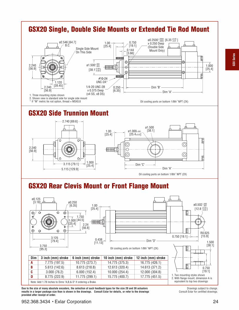
GSX20 Single, Double Side Mounts or Extended Tie Rod Mount
GSX20 Side Trunnion Mount
GSX20 Rear Clevis Mount or Front Flange Mount
24
0.144[3.66]
0.250[6.35]
0.750[19.1]
1/4-20 UNC-2Bx 0.375 Deep
(x4 SS, x8 DS)
1.00[25.4]
ø2.546 [64.7]B.C.
1.120[28.45]
2.240[56.9]
2.240[56.9]
Single Side MountOn This Side
ø1.500+.000 -.003
[38.1 ]+0.00 -0.08
#10-24UNC-2A#10-24
Dim "B"Dim "A"
ø0.2500x 0.250 Deep(Double Side Mount Only)
+.0000 -.0005 [6.35 ]+0.00
-0.01
1.000[25.4]
UNC-2A*
1. Two mounting styles shown2. With flange mount, dimension A is
equivalent to top two drawings
Drawings subject to change. Consult Exlar for certified drawings.
GSX
Serie
s
2.740 [69.6]
3.115 [79.1]
5.115 [129.9]
1.000[25.4]
1.00[25.4]
Dim "A"
ø1.000±.001
[25.4±0.03]
ø1.500 [38.1]
Dim "C"
2.240[56.9]
1. Three mounting styles shown2. Shown view is standard side for single side mount* If “M” metric tie rod option, thread = M5X0.8
Dim 3 inch (mm) stroke 6 inch (mm) stroke 10 inch (mm) stroke 12 inch (mm) strokeA 7.775 (197.5) 10.775 (273.7) 14.775 (375.3) 16.775 (426.1)B 5.613 (142.6) 8.613 (218.8) 12.613 (320.4) 14.613 (371.2)C 3.000 (76.2) 6.000 (152.4) 10.000 (254.4) 12.000 (304.8)D 8.775 (222.9) 11.775 (299.1) 15.775 (400.7) 17.775 (451.5)Note: Add 1.78 Inches to Dims "A,B,& D" if ordering a Brake.
Oil cooling ports on bottom 1/8th˝ NPT (2X)
Oil cooling ports on bottom 1/8th˝ NPT (2X)
Dim "D"0.750 [19.1]
R0.625[15.9]3.125
[79.4]
3.750[95.3]
ø0.125 [3.18]
1.750[44.5]1.000
[25.4]
1.00[25.4]
2.24[56.8]
ø0.250 [6.35]
0.750[19.1]
1.500[38.1]
0.438[11.13]
[12.8 ]+0.00 -0.03
ø0.502 +.000 -.001
Oil cooling ports on bottom 1/8th˝ NPT (2X)
Due to the size of many absolute encoders, the selection of such feedback types for the size 20 and 30 actuatorsresults in a larger package size than is shown in the drawings. Consult Exlar for details, or refer to the drawingsprovided after receipt of order.
952.368.3434 • Exlar Corporation

GSX30, Double Side Mounts or Extended Tie Rod Mount
GSX30 Side Trunnion Mount
GSX30 Rear Clevis Mount or Front Flange Mount
Ø 3.536[89.8]
3.100[78.7]MAX
3.046**[77.4]
1.523[38.68]
Single Side MountOn This Side
0.962[24.4]0.090[2.29]
Ø 2.000[50.8 ]
(x4 SS, x8 DS)
1/4-20 UNC-2Bx 0.38 Deep 0.250
[6.35] Dim "B"Dim "A"
1.750[44.5]
Ø 0.2500 +0.0000- 0.0005 0.00- 0.01
+0.003- 0.000+0.1 0.0
x 0.250 Deep(Double SideMount Only)
[6.35 ]
1.32[33.5]
1/4-20UNC-2A*
Drawings subject to change. Consult Exlar for certified drawings.
Dim 3 inch (mm) stroke 6 inch (mm) stroke 10 inch (mm) stroke 14 inch (mm) stroke 18 inch (mm) stroke
A 8.243 (209.4) 10.716 (272.2) 15.215 (386.5) 19.215 (488.1) 23.215 (589.7)B 6.147 (156.1) 8.620 (218.9) 13.119 (333.3) 17.119 (434.8) 21.119 (536.4)C 5.380 (136.7) 8.006 (203.4) 10.000 (254.0) 14.000 (355.6) 18.000 (457.2)D 9.486 (240.9) 11.959 (303.8) 16.458 (418.0) 20.458 (519.6) 24.458 (621.2)Note: Add 1.61 Inches to Dims "A, & D" if ordering a Brake.
25
±0.001
±0.03
3.546[90.1]
3.921[99.6]
1.000[25.4]
5.921[150.4]
Ø 1.000[25.40 ]
Ø 1.500[38.1]
1.32[33.5]
Dim "C"Dim "A"
3.100[78.7]MAX
1. Two mounting styles shown2. With flange mount, dimensionA is equivalent to top two drawings
+0.0000- 0.0010 0.00- 0.03
3.688[93.7]
5.250[133.4]
5.940[150.9]
2.430[61.72]
0.250[6.35]
Ø 0.397 (4X)[10.08] 1.32
[33.5]
0.438[11.13]
Dim "D"
Ø 0.7505[19.06 ]
0.993[25.2]
R 0.75019.1
1.250[31.8]
2.500[63.5]
3.100[78.7]MAX
1. Three mounting styles shown2. Shown view is standard side for single side mount* If “M” metric tie rod option, thread = M6X1** If using extended tie rods this dimension is 3.1 (78.7) MAX
Oil cooling ports on bottom 1/8˝ NPT front and 1/4˝ NPT rearIf a rear brake is used both ports are 1/8˝ NPT
Oil cooling ports on bottom 1/8˝ NPT front and 1/4˝ NPT rearIf a rear brake is used both ports are 1/8˝ NPT
Oil cooling ports on bottom 1/8˝ NPT front and 1/4˝ NPT rearIf a rear brake is used both ports are 1/8˝ NPT
Due to the size of many absolute encoders, the selection of such feedback types for the size 20 and 30 actuatorsresults in a larger package size than is shown in the drawings. Consult Exlar for details, or refer to the drawings
provided after receipt of order.
Exlar Corporation • 952.368.3434
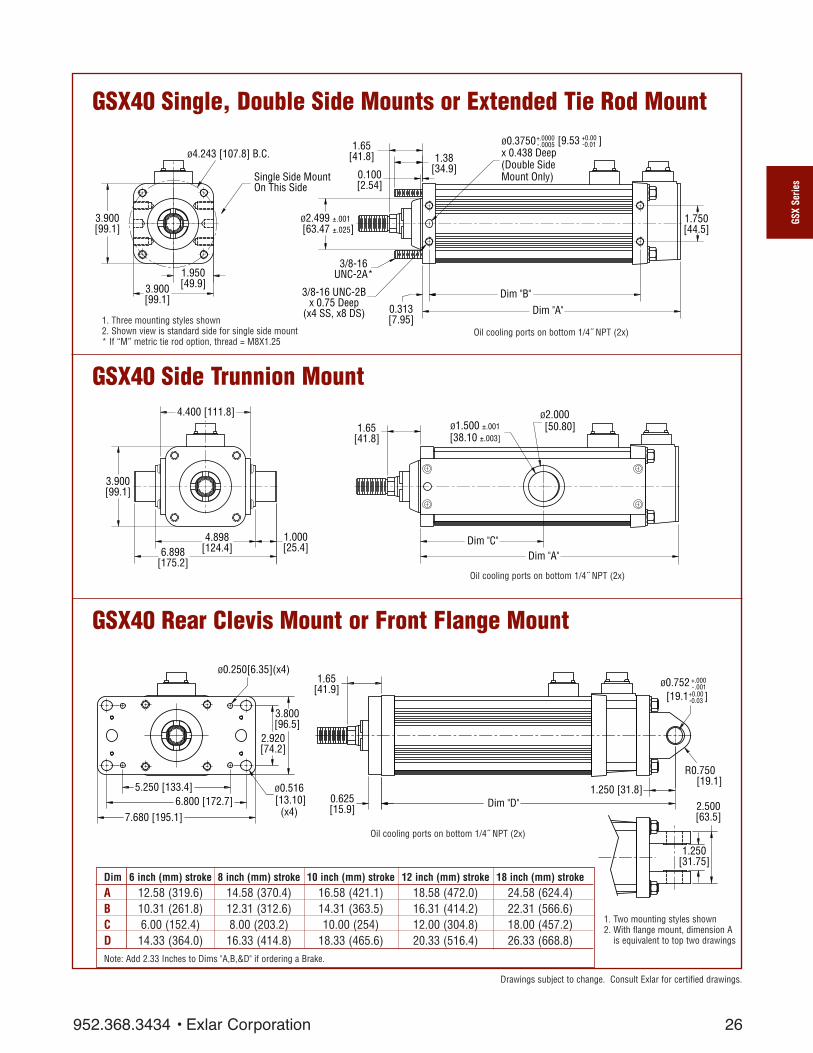
GSX40 Single, Double Side Mounts or Extended Tie Rod Mount
GSX40 Side Trunnion Mount
GSX40 Rear Clevis Mount or Front Flange Mount
26
1.950[49.9]
3.900[99.1]
1.65[41.8]
Dim "A"
1.750[44.5]
Dim "B"0.313[7.95]
3.900[99.1]
1.38[34.9]
ø2.499 ±.001[63.47 ±.025]
3/8-16UNC-2A
ø0.3750x 0.438 Deep(Double SideMount Only)
+.0000 -.0005 [9.53 ]+0.00
-0.01
0.100[2.54]
3/8-16 UNC-2Bx 0.75 Deep
(x4 SS, x8 DS)
ø4.243 [107.8] B.C.
Single Side MountOn This Side
3/8-16UNC-2A*
1. Three mounting styles shown2. Shown view is standard side for single side mount* If “M” metric tie rod option, thread = M8X1.25
1. Two mounting styles shown2. With flange mount, dimension A
is equivalent to top two drawings
Drawings subject to change. Consult Exlar for certified drawings.
Dim 6 inch (mm) stroke 8 inch (mm) stroke 10 inch (mm) stroke 12 inch (mm) stroke 18 inch (mm) strokeA 12.58 (319.6) 14.58 (370.4) 16.58 (421.1) 18.58 (472.0) 24.58 (624.4)B 10.31 (261.8) 12.31 (312.6) 14.31 (363.5) 16.31 (414.2) 22.31 (566.6)C 6.00 (152.4) 8.00 (203.2) 10.00 (254) 12.00 (304.8) 18.00 (457.2)D 14.33 (364.0) 16.33 (414.8) 18.33 (465.6) 20.33 (516.4) 26.33 (668.8)Note: Add 2.33 Inches to Dims "A,B,&D" if ordering a Brake.
GSX
Serie
s
1.65[41.8]
1.000[25.4]
4.898[124.4]6.898
[175.2]
3.900[99.1]
4.400 [111.8]
Dim "C"Dim "A"
ø1.500 ±.001[38.10 ±.003]
ø2.000 [50.80]
Dim "D"0.625[15.9]
6.800 [172.7]7.680 [195.1]
ø0.250[6.35](x4)
5.250 [133.4]
3.800[96.5]
ø0.516 [13.10]
(x4)
2.920[74.2]
1.65[41.9]
1.250 [31.8]
[19.1 ]+0.00 -0.03
ø0.752 +.000 -.001
R0.750 [19.1]
2.500[63.5]
1.250[31.75]
Oil cooling ports on bottom 1/4˝ NPT (2x)
Oil cooling ports on bottom 1/4˝ NPT (2x)
Oil cooling ports on bottom 1/4˝ NPT (2x)
952.368.3434 • Exlar Corporation

GSX50 Single, Double Side Mounts or Extended Tie Rod Mount
GSX50 Side Trunnion Mount
GSX50 Rear Clevis Mount or Front Flange Mount
27
1/2-13 UNC-2Bx .750 Deep
(x4 SS, x8 DS)
3.000[76.2]
Dim "B"0.406[10.3]
Dim "A"
1.50038.12.125
[54.0]
0.125[3.2]
x 0.500 Deep (2x)(Double Side Mount Only)
[12.7 ]0.0-0.0
0.5000 +0.0000-0.0005
3.000 +0.000-0.003
[76.2 ]+0.0-0.1
1/2-13 UNC-2A*
6.125 B.C.[155.6]
2.750[69.9]
5.500[139.7]
5.500[139.7]
Single Side MountOn This Side
1. Three mounting styles shown2. Shown view is standard side for
single side mount* If “M” metric tie rod option,
thread = M12X1.75
1. Two mounting styles shown2. With flange mount, dimension A is
equilavent to top two drawings
Drawings subject to change. Consult Exlar for certified drawings
Dim 6 inch (mm) stroke 10 inch (mm) stroke 14 inch (mm) strokeA 14.31 (363.5) 18.31 (465.1) 22.31 (566.7)B 11.12 (282.4) 15.12 (384.0) 19.12 (485.6)C 6.00 (152.4) 10.00 (254.0) 14.00 (355.6)D 16.56 (420.6) 20.56 (522.2) 24.56 (623.8)Note: Add 2.5 Inches to Dims "A,B,&D" if ordering a Brake.
Dim "C"
Dim "A"
2.125[54.0]
2.500[63.5]6.250
[158.8]
5.500[139.7]
7.000[177.8]
1.500[38.1]
10.000[254.0]
[50.8 ]0.00+-
2.000 0.001+-
2.125[54.0]
0.750[19.1] Dim "D"
1.000[25.4]
0.250
(4x)[6.4] 0.563
(4x)[14.3]
7.625
(4x)[193.7]
9.500[241.3]
4.875
(2x)[123.8]
3.250
(2x)[82.6]
6.500
(2x)[165.1]
1.500[38.1]
3.000[76.2]
[25.4 ]0.0-0.0
1.001+0.000-0.001
Oil cooling ports on bottom 1/4˝ NPT (2x)
Oil cooling ports on bottom 1/4˝ NPT (2x)
Oil cooling ports on bottom 1/4˝ NPT (2x)
Exlar Corporation • 952.368.3434

GSX60 Single, Double Side Mounts or Extended Tie Rod Mount
GSX60 Side Trunnion Mount
GSX60 Rear Clevis Mount or Front Flange Mount
28
3.000[76.2]
Dim "B"0.438[11.1] Dim "A"
6.800[172.7]
3.400[86.4]
1.94[49.4]
6.989[177.5]
0.125[3.18]
ø0.5000 x 0.625 Deep (Double Side Mount Only)
+.0000 - .0005
[12.7 ]+0.00 - 0.01
5/8-11 UNC-2Bx 0.625 Deep
(x4 SS, x8 DS)
ø7.778 [197.6] B.C.
ø3.375+.000 -.003
[85.73 ]+0.0 -0.08
9/16-12UNC-2A
1.65[41.8]
Single Side Mount OnThis Side
9/16-12UNC-2A*
1. Three mounting styles shown2. Shown view is standard side for single side mount* If “M” metric tie rod option, thread = M14X2
1. Two mounting styles shown2. With flange mount, dimension A
is equivalent to top two drawings
Drawings subject to change. Consult Exlar for certified drawings.
Dim 6 inch (mm) stroke 10 inch (mm) strokeA 15.23 (386.8) 19.23 (488.4)B 11.88 (301.8) 15.88 (403.3)C 6.00 (152.4) 10.00 (254.0)D 18.48 (469.4) 22.48 (571.0)
Note: Add 3.575 Inches to Dimensions "A,B,&D" if ordering a Brake.
GSX
Serie
s
7.800 [198.1]
12.550 [318.8]
8.550 [217.2]
6.989[177.5]
2.000[50.8]
ø2.500 +.000-.002
[63.50 ] +0.00-0.05
Dim "A"
1.944[49.4] ø3.500
[88.90]
Dim "C"
0.750[19.1]
1.944 [49.4]
12.500 [317.5]10.174 [258.4]
ø0.250 [6.35] (x4)
ø0.781 [19.8](x4)
8.125 [206.4]
6.800[172.7]
5.375[136.5]
2.500[63.50]
5.000[127.0]
Dim "D"
[44.53 ]+0.00 -0.04
ø1.753+.0000 -.0015
R 2.125 [53.98]2.500 [63.50]
Oil cooling ports on bottom 1/4˝ NPT (2x)
Oil cooling ports on bottom 1/4˝ NPT (2x)
Oil cooling ports on bottom 1/4˝ NPT (2x)
952.368.3434 • Exlar Corporation

GSX20 GSX30 GSX40 GSX50 GSX60
A 1.78 (45.21) 1.61 (40.9) 2.33 (59.18) 2.5 (63.5) 3.575 (90.8)
29
Dim "A"
Rear Brake Extension Option
*Consult Exlar for connector and wiring information if ordering brake option.
Exlar Corporation • 952.368.3434
*Brake connectorif needed.

Dim A 3 inch 6 inch 8 inch 10 inch 12 inch 14 inch 18 inch(mm) (mm) (mm) (mm) (mm) (mm) (mm)
stroke stroke stroke stroke stroke stroke stroke
GSX20 5.515 8.515 NA 12.500 14.515 NA NA(140.1) (216.3) NA (317.5) (368.7) NA NA
GSX30 6.932 9.832 NA 13.832 15.832 17.832 21.832(176.1) (249.7) NA (351.3) (402.1) (452.9) (554.5)
GSX40 NA 9.832 11.83 13.832 15.832 NA 21.832NA (249.7) (300.5) (351.3) (402.1) NA (554.5)
GSX50 NA 11.667 NA 15.667 NA 19.667 NANA (296.3) NA (397.9) NA (499.5) NA
GSX60 NA 10.461 NA 14.461 NA NA NANA (265.7) NA (367.3) NA NA NA
30
GSX20, GSX30, GSX40, GSX50 & GSX60 External Limit SwitchExtension Options
DIM "A"
36" Flying Leads
L1 L2 L3
The external limit switch option (requires anti-rotate option) for the GSX Series of linear actuators providesthe user with 1, 2 or 3 externally mounted adjustable switches for use as the end of travel limit switches orhome position sensors.
The number of switches desired is selected by ordering the L1, L2 or L3 option, in which 1, 2 or 3 switcheswill be provided, respectively.
The switches are 9-30 VDC powered, PNP output, with either normally open or normally closed logic opera-tion depending on the switch configuration ordered. Below is a diagram indicating which logic operationwill be provided for each switch, based on the option ordered.
Option SW1 SW2 SW3
L1 Not Supplied Normally Open Not SuppliedL2 Normally Closed Not Supplied Normally ClosedL3 Normally Closed Normally Open Normally Closed
Switch Type Exlar Part Number Turck Part Number
Normally Closed Switch 24631 BIM-INT-RP6XNormally Open Switch 22303 BIM-INT-AP6X
GSX
Serie
s
952.368.3434 • Exlar Corporation
31
Drawings subject to change. Consult Exlar for certified drawings.
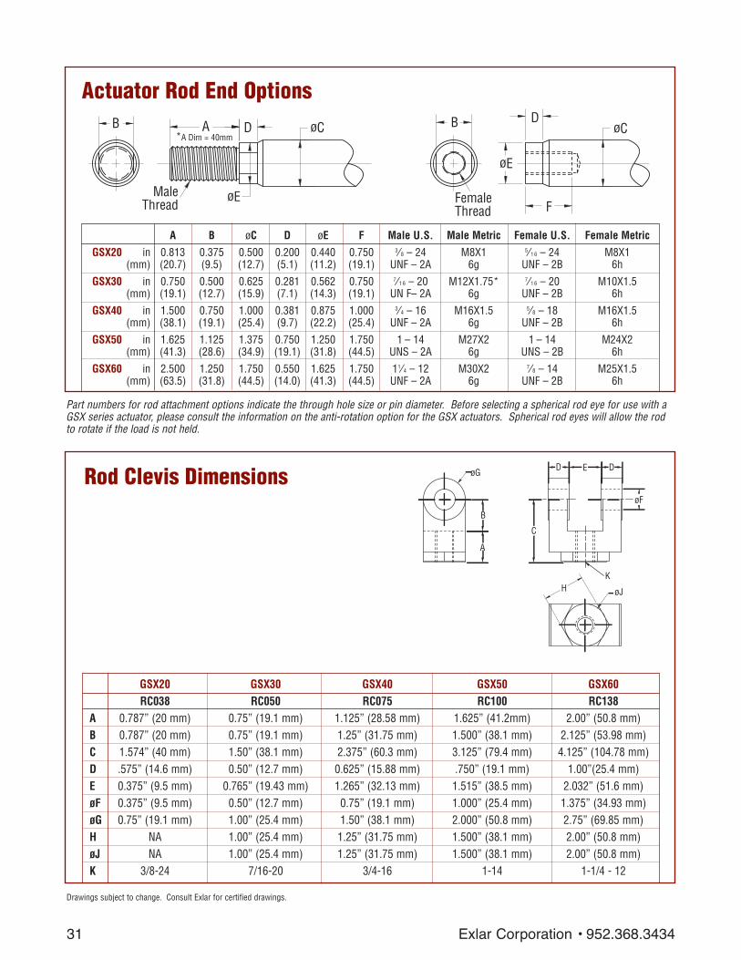
Part numbers for rod attachment options indicate the through hole size or pin diameter. Before selecting a spherical rod eye for use with aGSX series actuator, please consult the information on the anti-rotation option for the GSX actuators. Spherical rod eyes will allow the rodto rotate if the load is not held.
Actuator Rod End OptionsA øCD
øE
B
MaleThread
B D
øE
F
øC
FemaleThread
A B øC D øE F Male U.S. Male Metric Female U.S. Female Metric
GSX20 in 0.813 0.375 0.500 0.200 0.440 0.750 3⁄8 – 24 M8X1 5⁄1 6 – 24 M8X1(mm) (20.7) (9.5) (12.7) (5.1) (11.2) (19.1) UNF – 2A 6g UNF – 2B 6h
GSX30 in 0.750 0.500 0.625 0.281 0.562 0.750 7⁄1 6 – 20 M12X1.75* 7⁄1 6 – 20 M10X1.5(mm) (19.1) (12.7) (15.9) (7.1) (14.3) (19.1) UN F– 2A 6g UNF – 2B 6h
GSX40 in 1.500 0.750 1.000 0.381 0.875 1.000 3⁄4 – 16 M16X1.5 5⁄8 – 18 M16X1.5(mm) (38.1) (19.1) (25.4) (9.7) (22.2) (25.4) UNF – 2A 6g UNF – 2B 6h
GSX50 in 1.625 1.125 1.375 0.750 1.250 1.750 1 – 14 M27X2 1 – 14 M24X2(mm) (41.3) (28.6) (34.9) (19.1) (31.8) (44.5) UNS – 2A 6g UNS – 2B 6h
GSX60 in 2.500 1.250 1.750 0.550 1.625 1.750 11⁄4 – 12 M30X2 7⁄8 – 14 M25X1.5(mm) (63.5) (31.8) (44.5) (14.0) (41.3) (44.5) UNF – 2A 6g UNF – 2B 6h
*A Dim = 40mm
Rod Clevis DimensionsD DE
øF
C
B
A
øG
H øJ
K
GSX20 GSX30 GSX40 GSX50 GSX60RC038 RC050 RC075 RC100 RC138
A 0.787” (20 mm) 0.75” (19.1 mm) 1.125” (28.58 mm) 1.625” (41.2mm) 2.00” (50.8 mm)B 0.787” (20 mm) 0.75” (19.1 mm) 1.25” (31.75 mm) 1.500” (38.1 mm) 2.125” (53.98 mm)C 1.574” (40 mm) 1.50” (38.1 mm) 2.375” (60.3 mm) 3.125” (79.4 mm) 4.125” (104.78 mm)D .575” (14.6 mm) 0.50” (12.7 mm) 0.625” (15.88 mm) .750” (19.1 mm) 1.00”(25.4 mm)E 0.375” (9.5 mm) 0.765” (19.43 mm) 1.265” (32.13 mm) 1.515” (38.5 mm) 2.032” (51.6 mm)øF 0.375” (9.5 mm) 0.50” (12.7 mm) 0.75” (19.1 mm) 1.000” (25.4 mm) 1.375” (34.93 mm)øG 0.75” (19.1 mm) 1.00” (25.4 mm) 1.50” (38.1 mm) 2.000” (50.8 mm) 2.75” (69.85 mm)H NA 1.00” (25.4 mm) 1.25” (31.75 mm) 1.500” (38.1 mm) 2.00” (50.8 mm)øJ NA 1.00” (25.4 mm) 1.25” (31.75 mm) 1.500” (38.1 mm) 2.00” (50.8 mm)K 3/8-24 7/16-20 3/4-16 1-14 1-1/4 - 12
Exlar Corporation • 952.368.3434

GSX20 GSX30 GSX40 GSX50SRM038 SRM044 SRM075 SRF100
A 1.625” (41.3mm) 1.81” (46.0 mm) 2.88” (73.2 mm)øB .375” (9.525mm) 0.438” (11.13 mm) 0.75” (19.1 mm)C .906” (23.0mm) 1.06” (26.9 mm) 1.72” (43.7 mm)D 1.0” (25.6mm) 1.13” (28.7 mm) 1.75” (44.5 mm)E 12 deg 14 deg 14 degF .406” (10.3mm) 0.44” (11.1 mm) 0.69” (17.5 mm)G .500” (12.7mm) 0.56” (14.2 mm) 0.88” (22.3 mm)H .688” (17.7mm) 0.75” (19.1 mm) 1.13” (28.7 mm)J .562” (14.3mm) 0.63” (16.0 mm) 1.00” (25.4 mm)K 3/8-24 7/16-20 3/4-16
32
Drawings subject to change. Consult Exlar for certified drawings.
Spherical Rod Eye Dimensions
See GSX50
Sperical Rod Eye
drawing below.
Requires female
rod end.
D
A
H
FG
øB
C
J K
E
Ø1"R 1 3/8"
R 1 7/16"1 1/2"
1 7/8"
1"-14Thread
LUBE FITTING
7/8"
1 1/2"
GSX
Serie
s
952.368.3434 • Exlar Corporation
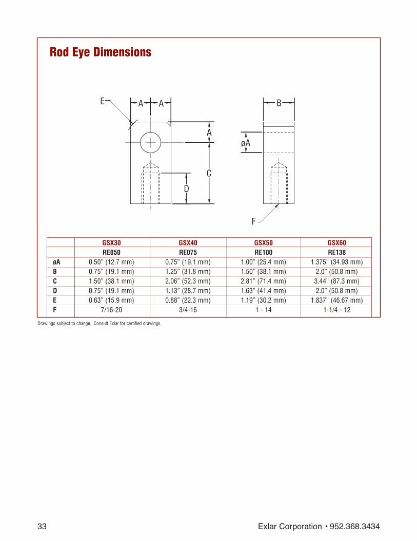
GSX30 GSX40 GSX50 GSX60RE050 RE075 RE100 RE138
øA 0.50” (12.7 mm) 0.75” (19.1 mm) 1.00” (25.4 mm) 1.375” (34.93 mm)B 0.75” (19.1 mm) 1.25” (31.8 mm) 1.50” (38.1 mm) 2.0” (50.8 mm)C 1.50” (38.1 mm) 2.06” (52.3 mm) 2.81” (71.4 mm) 3.44” (87.3 mm)D 0.75” (19.1 mm) 1.13” (28.7 mm) 1.63” (41.4 mm) 2.0” (50.8 mm)E 0.63” (15.9 mm) 0.88” (22.3 mm) 1.19” (30.2 mm) 1.837” (46.67 mm)F 7/16-20 3/4-16 1 - 14 1-1/4 - 12
33
Drawings subject to change. Consult Exlar for certified drawings.
AA
A
B
øA
C
D
F
E
Rod Eye Dimensions
Exlar Corporation • 952.368.3434

A B C øD øE
GSX20 2.28” 1.94” 0.17” 0.50” 0.095” CP050-Rear Clevis (57.9 mm) (49.28 mm) (4.32 mm) (12.7 mm) (2.41 mm)
GSX30 2.28” 1.94” 0.17” 0.50” 0.095” CP050-Rod eye, Rod Clevis (57.9 mm) (49.28 mm) (4.32 mm) (12.7 mm) (2.41 mm)
CP075-Rear Clevis 3.09” 2.72” 0.19” 0.75” 0.14”(78.5 mm) (69.1 mm) (4.82 mm) (19.1 mm) (3.56 mm)
GSX40CP075-Rod eye, Rod Clevis 3.09” 2.72” 0.19” 0.75” 0.14”
Spherical Eye, Rear Clevis (78.5 mm) (69.1 mm) (4.82 mm) (19.1 mm) (3.56 mm)
GSX50CP100-Rod eye, Rod Clevis 3.59” 3.22” 0.19” 1.00” 0.14”
Spherical Eye, Rear Clevis (91.2 mm) (81.8 mm) (4.82 mm) (25.4 mm) (3.56 mm)
GSX60 4.66” 4.25” 0.20” 1.375” 0.173”CP138-Rod eye, Rod Clevis (118.3 mm) (108 mm) (5.08 mm) (34.93 mm) (4.39 mm)
CP175-Rear Clevis 5.656” 5.25” 0.203” 1.750” 0.173”(143.6 mm) (133.3 mm) (5.15 mm) (4.44 mm) (4.39 mm)
34
Clevis Pin Dimensions
C CB
A
øE
øD
Drawings subject to change. Consult Exlar for certified drawings.GS
X Se
ries
952.368.3434 • Exlar Corporation

35
AA = GSX Actuator Size20 = 2 inch frame 30 = 3 inch frame 40 = 4 inch frame50 = 5 inch frame60 = 7 inch frameBB = Stroke Length03 = 3 inches (GSX20, GSX30)06 = 5.9 inches (GSX30)
6 inches (GSX20, GSX40,GSX50, GSX60)
08 = 8 inches (GSX40)10 = 10 inches (all models)12 = 12 inches (GSX20, GSX30,
GSX40)14 = 14 inches (GSX30, GSX50)18 = 18 inches (GSX30, GSX40)CC = Lead01 = 0.1 inch (GSX20, GSX30,
GSX40, GSX50)7
02 = 0.2 inch (GSX20, GSX30,GSX40, GSX50)
03 = 0.25 inch (GSX60)04 = 0.4 inch (GSX20 only)05 = 0.5 inch (GSX30, GSX40,
GSX50, GSX60)08 = 0.75 inch (GSX40)8
10 = 1.0 inch (GSX50, GSX60)9
D = ConnectionsM = Manufacturer’s Connector6
I = Exlar standard M23 style10
A = MS style (anodized)D = MS style (electroless nickel) B = Embedded leads 3 ft. std.P = Embedded leads w/plug
3 ft. std.w/’A’ plugJ = Embedded leads w/”I” plug,
3´ stdX = Special (please specify)E = MountingS = Side tapped mounting holesD = Double side tapped
mounting holesE = Extended tie rodsF = Front flangeR = Rear flangeB = Front and rear flangeT = TrunnionC = Rear clevisX = Special (please specify)M = Metric extended tie rodsF = Rod EndM = Male, US std. ThreadA = Male, Metric std. ThreadF = Female, US std. ThreadB = Female, Metric ThreadX = Special (please specify)
GGG = Feedback Type (Also specify the Amplifier/DriveModel being used when ordering)-Standard Incremental Encoder – 2048 line with commuta-tion, 5vdc
-Standard Resolver – Size 15 resolver-Motor files for use with select Emerson/CT, Rockwell /ABand Danaher/Kollmorgen Drives are available atwww.exlar.comCustom Feedback - Please consult application engineering:XX1 = Wiring and feedback device information must be
provided and new feedback callout will be createdMounting Only - Please consult application engineering:001 = Feedback Mount – .375 inch shaft ready for size 15
resolver or encoder002 = Feedback Mount – 8 mm shaft ready for feedback
deviceAllen-Bradley/Rockwell: (Actuators used with Kinetixand/or Sercos based control systems require a 3rd partymotion database purchased from AB/Rockwell. Pleasecontact your AB/Rockwell representative for support.)AB1 = Standard Incremental Encoder - F/S/H motor wiring
w/MS connectors for 'M' optionAB5 = Stegmann SRM050 Hyperface multi-turn absolute
encoder - MPL 100mm or higher motor wiringw/MS connectors for 'M' option – Plug & Play feed-back option
AB6 = Standard ResolverAB7 = Standard Incremental Encoder - MPL 100mm or
higher motor wiring w/MS connectors for 'M' option AB8 = Standard Incremental Encoder - MPL 75mm or less
motor wiring w/M23 euro connectors for 'M' optionAB9 = Hyperface Stegmann SRM050 multi-turn absolute
encoder - MPL 75mm or less motor wiring w/M23euro connectors for 'M' option – Plug & Play feed-back option
ABA = Hyperface Stegmann SKM036 multi-turn absoluteencoder - MPL 215mm or higher motor wiringw/MS connectors for 'M' option - 460V Stator only– Plug & Play feedback option
ABB = Hyperface Stegmann SKM036 multi-turn absoluteencoder - MPL 75mm or less motor wiring w/M23euro connectors for 'M' option - 460V Stator only –Plug & Play feedback option
AMKASYN:AK1 = EnDat Heidenhain EQN1325 multi-turn absolute
encoder - DS motor wiring w/M23 euro connectorsfor 'M' option
AK2 = EnDat Heidenhain EQN1125 multi-turn absoluteencoder - DS motor wiring w/M23 euro connectorsfor 'M' option
Advanced Motion Control:AM1 = Standard Incremental Encoder AM2 = Encoder 1000 line, with commutation, 5 VDCAM3 = Standard ResolverAM5 = Encoder 5000 line, with commutation, 5 VDCAPI Controls:AP1 = Standard ResolverAP2 = Standard Incremental Encoder Aerotech:AR1 = Encoder 5000 line, with commutation, 5 VDCAR2 = Standard Incremental Encoder ABB Robot:BB1 = LTN ResolverBaldor:BD2 = Standard Resolver BD3 = Standard Incremental Encoder
GSX AA - BB CC - D E F - GGG - HHH - II - {XX..XX}GSX Series OrderingInformation Beckhoff:
BE1 = EnDat Heidenhain EQN1125 multi-turn absoluteencoder - AM motor wiring w/M23 euro connec-tors for 'M' option
Baumueller:BM2 = Standard ResolverB&R Automation:BR1 = Standard ResolverBR2 = EnDat Heidenhain EQN1325 multi-turn absolute
encoder – 8LS/8LM motor wiring w/M23 euroconnectors for 'M' option
Comau Robot:CM1 = Standard ResolverCopley Controls:CO1 = Standard Incremental EncoderCO2 = Standard ResolverControl Techniques/Emerson:CT1 = Hyperface Stegmann SRM050 multi-turn absolute
encoder - FM/UM/EZ motor wiring w/M23 euroconnectors for 'M' option
CT2 = Hyperface Stegmann SRM050 multi-turn absoluteencoder – NT motor wiring w/MS connectors for'M' option
CT3 = Hyperface Stegmann SKM036 multi-turn absoluteencoder – FM/UM/EZ motor wiring w/M23 euroconnectors for 'M' option
CT4 = Standard Incremental Encoder – FM/UM/EZ motorwiring w/M23 euro connectors for 'M' option
CT5 = Standard Resolver – FM/UM/EZ motor wiringw/M23 euro connectors for 'M' option
CT7 = Encoder 5000 line, with commutation, 5 VDC –FM/UM/EZ motor wiring w/M23 euro connectorsfor 'M' option
Delta Tau Data Systems:DT1 = Encoder 1000 line, with commutation, 5 VDCDT2 = Standard ResolverElmo Motion Control:EL1 = Standard ResolverEL2 = Standard Incremental EncoderEL3 = EnDat Heidenhain EQN1125 multi-turn absolute
encoderEmerson/Control Techniques:EM2 = Standard Incremental Encoder – NT motor wiring
w/MS connectors for 'M' optionEM5 = Encoder 5000 line, with commutation, 5 VDC –
NT motor wiring w/MS connectors for 'M' optionElau:EU1 = Hyperface Stegmann SRS050 single-turn absolute
encoder – SH motor wiring w/MS connectors for'M' option
EU3 = Hyperface Stegmann SKS036 single-turn absoluteencoder– SH motor wiring w/MS connectors for'M' option
EU4 = Hyperface Stegmann SKM036 multi-turn absoluteencoder– SH motor wiring w/MS connectors for'M' option
Exlar:EX4 = Standard ResolverFanuc Robot/CNC:FA1 = PULSECODER alpha i AR128FA2 = PULSECODER alpha A64G&L Motion Control/Danaher Motion:GL1 = Standard Incremental Encoder – HSM motor
wiring w/ MS connectors for 'M' optionGL2 = Standard Incremental Encoder – LSM-MSM motor
wiring w/M23 euro connectors for 'M' option
Exlar Corporation • 952.368.3434

36
HHH = Motor Stator – All 8 Pole2
118 = 1 stack, 115 Vrms218 = 2 stack, 115 Vrms318 = 3 stack, 115 Vrms138 = 1 stack, 230 Vrms238 = 2 stack, 230 Vrms338 = 3 stack, 230 Vrms158 = 1 stack, 400 Vrms258 = 2 stack, 400 Vrms358 = 3 stack, 400 Vrms168 = 1 stack, 460 Vrms268 = 2 stack, 460 Vrms368 = 3 stack, 460 VrmsII = Motor Speed24 = 2400 rpm, GSX50, GSX60 30 = 3000 rpm, GSX30, GSX4050 = 5000 rpm, GSX2001-99 = Customer specified base speed
XX .. XX = Options Travel OptionsPF = Preloaded follower1
AR = External Anti-rotate assemblyRB = Rear Electric Brake4
XT = Special Travel Option (see pg. 22), and hightemp protective bellows or splined main rod
L1/L2/L3 = External Limit SwitchesMotor OptionsXM = Special motor optionXL = Special lubrication or use of oil coolingHousing OptionsFG = Food grade paint5EN = Electroless nickel plating5
HC = Type III hard coat anodized, class 15
SS = Stainless steel housing5
XH = Special housing optionAbsolute Linear FeedbackLT = VRVT, including signal conditioner1, 3
1. The dynamic load rating of zero backlash, pre-loaded screws is 63% of the dynamic loadrating of the standard non-preloaded screws.The calculated travel life of a preloaded screwwill be 25% of the calculated travel life of thesame size and lead of a non-preloaded screw.Preloaded follower is not available withabsolute linear (LT) internal feedback option.
2. Stator voltage and pole options allow for cata-log rated performance at varying amplifier busvoltages and pole configuration requirements.Refer to perfomance specification on pages10-11 for availability of 3 stack stator.
3. Linear feedback is not available in the GSX20and not available in the GSX30, 14˝ and 18˝.
4. The brake option may require a third cable,consult Exlar.
5. These housing options would typically beaccompanied by the choice of the electrolessnickel connectors if a connectorized unit wereselected. This choice may also indicate theneed for special material main rods orflanges.
6. Available as described in Feedback Types.7. 0.1 lead not available above 12˝ stroke in
GSX40 or 10˝ stroke in GSX50.8. 0.75 lead not available above 12˝.9. 1.0 lead not available above 10˝ stroke.10. GSX60 uses M40 size 1.5 power connector.
GSX
Serie
s
GSX Series Ordering Information
GL3 = Standard Incremental Encoder – NSMmotor wiring w/MS connectors for 'M'option
GL4 = EnDat Heidenhain EQN1125 multi-turnabsolute encoder – AKM motor wiringw/M23 euro connectors for 'M' option
Infranor:IF1 = Standard ResolverIndramat/Bosch-Rexroth:IN1 = EnDat Heidenhain EQN1325 multi-turn
absolute encoder – MKD/MHD motorwiring w/M23 euro connectors for 'M'option
IN5 = EnDat Heidenhain EQN1125 multi-turnabsolute encoder – MKD/MHD motorwiring w/M23 euro connectors for 'M'option
IN6 = Standard Resolver – MKD/MHD motorwiring w/M23 euro connectors for 'M'option
IN7 = Hyperface Stegmann SRM050 multi-turn absolute encoder – MSK motorwiring w/M23 euro connectors for 'M'option – plug & play option
Jetter Technologies:JT1 = Standard Resolver – JH/JL motor wiring
w/M23 euro connectors for 'M' optionKollmorgen/Danaher:KM4 = EnDat Heidenhain EQN1325 multi-turn
absolute encoder – AKM motor wiringw/M23 euro connectors for 'M' option
KM5 = Standard Resolver – AKM motor wiringw/M23 euro connectors for 'M' option
KM6 = Standard Incremental Encoder – AKMmotor wiring w/ M23 euro connectorsfor 'M' option
Kuka Robot:KU1 = Tyco Size 21 ResolverKawasaki Robot:KW1 = Kawasaki Special EncoderLenze/AC Tech: LZ1 = Hyperface Stegmann SRM050 multi-
turn absolute encoder – MCS motorwiring w/M23 euro connectors for 'M'option
LZ5 = Standard Resolver – MCS motor wiringw/ M23 euro connectors for 'M' option
LZ6 = Standard Incremental Encoder – MCSmotor wiring w/ M23 euro connectorsfor 'M' option
Matuschek:MC1 = LTN ResolverModicon:MD1 = Standard ResolverMoog:MG1 = Standard ResolverMotoman Robot:MM1 = Yaskawa Serial EncoderMetronix:MX1 = Standard ResolverMX2 = Hyperface Stegmann SKM036 multi-
turn absolute encoderMX3 = EnDat Heidenhain EQN1125 multi-turn
absolute encoder
Nachi Robot:NC1 = Tamagawa Serial EncoderOrmec:OR1 = Standard Resolver OR2 = Standard Incremental Encoder – G
series motor wiring w/ MS connectorsfor 'M' option
Parker Compumotor:PC6 = Standard Incremental Encoder – SMH
motor wiring w/M23 connectors for'M' option – European only
PC7 = Standard Resolver – SMH motorwiring w/M23 connectors for 'M'option – European only
PC8 = Standard Incremental Encoder – MPPseries motor wiring w/PS connectorsfor 'M' option – US Only
PC9 = Hyperface Stegmann SRM050 multi-turn absolute encoder – MPP motorwiring w/PS connectors for 'M' option– US Only
PC0 = Standard Resolver – MPP motor wiringw/PS connectors for 'M' option – USOnly
Pacific Scientific:PS2 = Standard Incremental EncoderPS3 = Standard Resolver – PMA motor wiring
w/M23 connectors for 'M' optionStober Drives:SB3 = EnDat Heidenhain EQN1125 multi-turn
absolute encoder – ED/EK motorwiring w/M23 euro connectors for 'M'option
Seimens:SM2 = Standard Resolver – 1FK7 motor
wiring w/M23 connectors for 'M'option
SM3 = EnDat Heidenhain EQN1325 multi-turnabsolute encoder – 1FK7 motor wiringw/M23 euro connectors for 'M' option
SM4 = EnDat Heidenhain EQN1125 multi-turnabsolute encoder – 1FK7 motor wiringw/M23 euro connectors for 'M' option
SM5 = Heidenhain Incremental Encoder–1FK7 motor wiring w/M23 euro con-nectors for 'M' option
SEW/Eurodrive:SW1 = Standard Resolver – CM motor wiring
w/ M23 euro connectors for 'M'option
SW2 = Standard Incremental EncoderSW3 = Hyperface Stegmann SRM050 multi-
turn absolute encoder – CM motorwiring w/ M23 euro connectors for'M' option
Whedco/Fanuc:WD1 = Standard ResolverYaskawa:YS2 = Yaskawa Serial Encoder – SGMGH
motor wiring 40/50/60 Exlar FrameSizes
YS3 = Yaskawa Serial Encoder – SGMGHmotor wiring 20/30 Exlar Frame Sizes
952.368.3434 • Exlar Corporation