
Series FXA with DFC Chemical Injection Pump Operating … … · 3.3 Checking the Charge Pressure...
22
Series FXA Chemical Injection Pump with Flow Control Technology Operating Manual CP-MAN-PRD-FXA DFC REV01 EFF. DATE 01/01/16 Page 1 of 22 CheckPoint Headquarters CheckPoint UK CP Pumps & Systems FZE CheckPoint Systems Pte Ltd 21356 Marion Lane C2/C3 Lombard Centre P.O. Box 262131 21 Toh Guan Road East Mandeville, Louisiana 70471 Kirkhill Place, Kirkhill Industrial Estate Jebel Ali Free Zone, FZS1 BL 06 #04-17 Toh Guan Centre United States of America Dyce, Aberdeen AB21 0GU Scotland Dubai, U. A. E. Singapore 608 609 +1 (504) 340-0770 +44 (0)1224 775205 +971 (4) 8806278 +65 6261 7687 Series FXA with DFC Chemical Injection Pump Operating Manual
-
Upload
nguyendung -
Category
Documents
-
view
213 -
download
0
Transcript of Series FXA with DFC Chemical Injection Pump Operating … … · 3.3 Checking the Charge Pressure...

Series FXA Chemical Injection Pump with Flow Control Technology
Operating Manual
CP-MAN-PRD-FXA DFC REV01 EFF. DATE 01/01/16 Page 1 of 22
CheckPoint Headquarters CheckPoint UK CP Pumps & Systems FZE CheckPoint Systems Pte Ltd 21356 Marion Lane C2/C3 Lombard Centre P.O. Box 262131 21 Toh Guan Road East
Mandeville, Louisiana 70471 Kirkhill Place, Kirkhill Industrial Estate Jebel Ali Free Zone, FZS1 BL 06 #04-17 Toh Guan Centre United States of America Dyce, Aberdeen AB21 0GU Scotland Dubai, U. A. E. Singapore 608 609
+1 (504) 340-0770 +44 (0)1224 775205 +971 (4) 8806278 +65 6261 7687
Series FXA with DFC Chemical Injection Pump
Operating Manual

Series FXA Chemical Injection Pump with Flow Control Technology
Operating Manual
CP-MAN-PRD-FXA DFC REV01 EFF. DATE 01/01/16 Page 2 of 22
TABLE OF CONTENTS
1. PUMP INSTALLATION 3
1.1 Process Design & Setup ....................................................................................................................... 3
1.2 Connecting the Chemical Supply ....................................................................................................... 6
1.3 Connecting the Power Supply ............................................................................................................ 7
1.4 Motor Requirements ........................................................................................................................... 7
2. PUMP OPERATION 7
2.1 Bleeding/Priming the Injector Head .................................................................................................. 7
2.2 Adjusting the Pump Delivery Volume ............................................................................................... 8
2.3 Setting Delivery Volume – VFD or Variator ....................................................................................... 9
2.4 Setting Delivery Volume - DFC .......................................................................................................... 12
2.5 Packing Adjustment .......................................................................................................................... 13
2.6 Packing Replacement ........................................................................................................................ 14
3. PISTON ACCUMULATOR (PA) 16
3.1 Charging the PA .................................................................................................................................. 16
3.2 Checking the PA for Leaks ................................................................................................................ 16
3.3 Checking the Charge Pressure ......................................................................................................... 17
4. PUMP MAINTENANCE 18
4.1 Lubrication ......................................................................................................................................... 19
5. TROUBLESHOOTING 20
5.1 Pump runs, but chemical does not discharge at the correct rate ............................................... 20
5.2 Pump Does Not Stroke ...................................................................................................................... 21
5.3 Pump is Excessively Noisy ................................................................................................................ 21
5.4 Chemical Leakage from Packing ...................................................................................................... 21
5.5 Unable to prime pump ...................................................................................................................... 22
5.6 Other Problems .................................................................................................................................. 22

Series FXA Chemical Injection Pump with Flow Control Technology
Operating Manual
CP-MAN-PRD-FXA DFC REV01 EFF. DATE 01/01/16 Page 3 of 22
Congratulations! You have chosen the finest, most versatile electrically driven chemical injection pump made; designed to exacting specifications for long life, reliable performance, and low maintenance. To ensure proper operation and to maximize the Series FXA’s durability, please read and follow this manual. Failure to correctly install and maintain the pump is the primary cause of premature pump failure and voids the product warranty.
NOTE: This IOM applies to the CheckPoint FXA Electric Chemical Injector Pumps, part number FX0125-(FXA Code)-(Injector Assembly) for 1250 style heads, and FX0150-(FXA Code)-(Injector Assembly) for 1500 style heads.
CheckPoint FXA Pump w/Direct Flow Control ™. (Patent Pending)
This injector utilizes our revolutionary new DFC technology, which replaces traditional mechanical stroke length adjustment mechanisms and electronic speed controls. The CheckPoint Direct Flow Control (DFC) is an elegant, intrinsically safe device that replaces the discharge check valve and controls the pump flow rate by precisely adjusting the apparent size of the pressure chamber.
Advantages of CheckPoint DFC technology:
o API 674 and 675 compliant o Intrinsically safe o Extreme reliability – only a single additional moving part versus a totally non-adjustable pump o Highly repeatable and accurate o Zero maintenance or lubrication required o Replaces expensive, and often complicated VFD/VSD systems o ATEX certification pending o Maintains desirable high dosing frequency at all relevant flow rates o Continuous flow capability o Effective on plunger or diaphragm style pump heads o Eliminates archaic, elaborate, expensive, and unreliable stroke length adjustment mechanisms
prevalent on all currently-available API 674 and 675-compliant electric pumps o US and international patents pending
1. PUMP INSTALLATION
1.1 Process Design & Setup 1.1.1 Before installation, please inspect the pump carefully. If the pump appears to have sustained damage in transit, call your CheckPoint Authorized Distributor or CheckPoint Customer Service directly at +1 (800) 847-7867, +1 (504) 340-0770 or [email protected] to confirm and report damage. If it is determined that damage occurred in transit, a carrier claim would be required.

Series FXA Chemical Injection Pump with Flow Control Technology
Operating Manual
CP-MAN-PRD-FXA DFC REV01 EFF. DATE 01/01/16 Page 4 of 22
FIGURE 1: TYPICAL INSTALLATION SCHEMATIC
CheckPoint packages are available for the Series FXA pumps that contain all necessary components as indicated within the Package Limit Line. We can supply packages that contain ALL the components, including the tank, mounted on a single skid with or without full leak containment.
1. Suction line block valve 4. Calibration Gauge Block Valve 7. Discharge line block valve 10. Discharge Pressure Gauge
2. CP Chemical Filter* 5. CP Calibration Gauge* 8. PRV – Discharge Lline 11. Discharge Check Valve
3. Piston Accumulator* 6. Tank Gauge 9. CP FXA Chemical Pump* 12. DFC*
All items in Fig 1. can be purchased from CheckPoint. Call today for our latest prices on pumps, gauges, packages and other components.
*CheckPoint OEM products
1.1.2 Referring to Figure 1, ensure that all necessary components are present in your injection system and are in good working order. All the components shown above are recommended by CheckPoint to maximize pump life and productivity. In the event that you have questions regarding best practices, or need to purchase additional components, please contact CheckPoint for assistance. Representatives are on staff & available to answer your process questions. CheckPoint Engineers are also available to assist in system design. The CP Engineered Solutions Department can be utilized for custom design and build options.
NOTE: In Figure 1, the secondary chemical filter is optional under certain conditions but highly recommended.
NOTE: Chemical filters should be used as a final precaution to prevent contaminants from entering
the pump not as the primary means to clean chemical.
1.1.3 CheckPoint requires horizontal mounting for the Series FXA pump. Improper mounting will result in oil leakage from the breather vent. The FXA Base is provided to ensure proper orientation.

Series FXA Chemical Injection Pump with Flow Control Technology
Operating Manual
CP-MAN-PRD-FXA DFC REV01 EFF. DATE 01/01/16 Page 5 of 22
A suction-side calibration gauge or discharge flow meter is the only means to accurately set the pump flow rate. Many variables, including temperature, chemical viscosity, etcetera, preclude the use of tables, graphs and formulas to determine the rate of injection. Without a calibration gauge or flow meter, it cannot be determined if the pump is primed and functioning normally. For instructions on the proper use of a suction-side calibration gauge, please read Section NOTE: “When using a VFD or Variator the pumps stroke rate is changed to achieve the desired flow rate.
1.1.4 Determine Delivery Volume Using a Calibration Gauge”. The proper placement of a calibration gauge (labeled #5) is shown in Figure 1. CheckPoint offers a complete range of accurate and durable calibration gauges and discharge-side flow meters.
NOTE: It is necessary to attach a vent tube to the top of all calibration gauges, chemical tanks, and tank level gauges. The height of the top of each vent tube should always be greater than the highest possible liquid level in the system. Proper vent tubes should have means to prevent water entry, such as a 180 degree bend.
1.1.5 CP always recommends flooded suction; chemicals known to gas off require a flooded suction. However, the Series FXA does not require flooded suction or positive chemical pressure to prime. The FXA may be mounted above the chemical container. For a chemical with average viscosity, the pump will pull gas out of the chemical line and depending on plunger size can prime from up to twelve feet above the liquid level in the tank. This feature is dependent upon proper adherence to all points made in Paragraph 1.1.6 below.
1.1.6 ALL COMPONENTS AND PIPEWORK BETWEEN THE CHEMICAL TANK AND THE SUCTION CHECK VALVE OF THE PUMP MUST BE 100% BUBBLE-TIGHT AND FULLY COMPATIBLE WITH THE CHEMICAL AND WITH EACH OTHER. FAILURE TO ADHERE STRICTLY TO THIS DIRECTIVE WILL LEAD TO LOSS OF PRIME AND DAMAGE TO THE PLUNGER AND PLUNGER SEAL.
SPECIFICALLY:
1.1.7 All fittings and screw-on joints without Teflon™ tape or other equivalent sealant may allow air at atmospheric pressure to enter the suction tubing, even when no chemical leakage is visible.
1.1.7.1 Dissimilar metals in the suction side of the injection system may react with each other, creating gas bubbles that will be carried into the pump head. All suction components, tubing, pipe, fittings, and valves must be composed of similar or compatible materials. Please note that CheckPoint offers wetted parts comprised of 316 SS, Hastelloy C, PVC, Titanium and Alloy 20.
1.1.8 The pump may be mounted to a skid or other surface in a number of ways; however, clamping around outside of the pump can permanently affect the cylindricity of the injection head and/or FXA eccentric drive and may damage the protective coating, thereby voiding the product warranty. Proper mounting techniques increase accessibility during maintenance and troubleshooting. Your CheckPoint FXA purchase includes a standard pre-drilled base for proper pump mounting.
1.1.9 Always check to ensure that all process block valves (labeled Nos. 1, 4 & 7 in Figure 1) are closed prior to disconnecting or re-installing any chemical injection pump. There should always be a block valve placed between the pump and the process flow, gas supply, and the chemical supply. Conversely, while the pump is running, all such block valves should always be open.
1.1.10 The pump suction line should be sized appropriately based on the flow rate to avoid cavitation. A general rule of thumb is to size the suction line such that instantaneous flow velocity through the line does not exceed 2 feet per second at any point. Additional allowances may be needed for multiple pump

Series FXA Chemical Injection Pump with Flow Control Technology
Operating Manual
CP-MAN-PRD-FXA DFC REV01 EFF. DATE 01/01/16 Page 6 of 22
installations, extremely viscous chemicals and for chemicals with high vapor pressures; contact CheckPoint or your Authorized CheckPoint Distributor for design assistance.
1.1.11 TO AVOID OVER-PRESSURING CHEMICAL DISCHARGE LINES, CHECKPOINT REQUIRES PLACING A PROPERLY TESTED AND CALIBRATED PRESSURE RELIEF VALVE BETWEEN THE DISCHARGE PORT OF THE PUMP AND THE PROCESS FLOW. THE PRESSURE RELIEF VALVE DISCHARGE CAN BE RUN TO A TEE UPSTREAM OF THE PUMP’S CHEMICAL SUCTION CHECK VALVE OR RE-ROUTED TO TANK. FAILING TO USE A PRV IS EXTREMELY DANGEROUS. EXCESSIVE PRESSURE MAY LEAD TO CATASTROPHIC FAILURE OF PROCESS EQUIPMENT OR BODILY HARM. CHECKPOINT IS NOT RESPONSIBLE FOR ANY DAMAGE CAUSED BY OVER-PRESSURIZED CHEMICAL. CheckPoint offers a range of pressure relief valves suitable for use with the FXA pump.
CAUTION: When using a pressure relief valve, the chemical tank MUST BE properly vented to atmosphere. Venting helps avoid the possibility of tank over-pressurization if the pressure relief valve actuates.
1.1.12 Depending on a variety of factors, pulsation dampeners or suction accumulators may be required in your installation. Consult with CheckPoint if you have any concerns about pulsation or NPSHa.
1.1.13 A DFC requires an accumulator installed between the DFC and the in line check valve for proper operation. CheckPoint provides a piston accumulator (PA) designed specifically for the DFC. The proper charge for this PA is 20% - 25% of the maximum discharge pressure. For instructions on how to charge the accumulator, see section 3.1 ”Charging the PA”.
NOTE: The CheckPoint piston accumulator designed for the DFC is charged to 20% - 25% of max. discharge pressure.
1.2 Connecting the Chemical Supply 1.2.1 Always clean suction lines and check chemical containers to ensure that they are free of all foreign matter, sand, sludge, or chemical buildup.
NOTE: Even new chemical tanks can contain debris which may cause system damage. Removing foreign debris from suction lines and chemical containers will substantially extend the life of the packing and other pump components.
NOTE: Use of a pre-suction in-line chemical filter is indicated if early packing failure is observed. Abrasive particles carried into the pump through suction plumbing is a common cause of packing failure. CheckPoint offers a range of chemical filters suitable for use with the FXA pump.
CAUTION: Substantial scoring of the plunger can lead to premature packing failure and severe leakage of chemical into the surrounding environment.
1.2.2 Connect the chemical suction line to the suction check valve on the pump head. The suction check valve is a male 1/4" NPT for the 1250 type headed injectors and male ½” or ¾” NPT for the 1500 type headed injectors. Do not over-tighten NPT connections.
NOTE: To prevent leakage apply Teflon™ tape, or equivalent thread sealant, to the check valve threads prior to attachment.

Series FXA Chemical Injection Pump with Flow Control Technology
Operating Manual
CP-MAN-PRD-FXA DFC REV01 EFF. DATE 01/01/16 Page 7 of 22
NOTE: To operate properly, the check valve MUST remain directly attached to the chemical head. Never re-locate the suction check valve away from the chemical head .
1.2.3 Connect your discharge line to the DFC or pump discharge check valve. Care must be taken not to over-tighten NPT connections.
NOTE: The DFC replaces the standard discharge check valve.
Open the process block valve (shown as number 7 in Fig 1), allowing the process pressure to reach the chemical head or in-line check valve. Observe & correct any leakage.
CAUTION: The Series FXA pumps are capable of producing pressures in excess of 15K PSI. If the discharge line is blocked for any reason, the pump can generate pressures in excess of the indicated rated pressures. A relief valve MUST be placed between the discharge port and the process flow to PREVENT CATASTROPHIC FAILURE OF PROCESS EQUIPMENT OR BODILY HARM. CHECKPOINT IS NOT RESPONSIBLE FOR ANY DAMAGE CAUSED BY OVER-PRESSURIZATION.
NOTE: Always open the process block valve prior to operating the pump. Operating the pump with a closed block valve can generate enough pressure to rupture the discharge, damage process equipment and chemical head. Improper procedures may reduce the life of your CheckPoint pump.
1.3 Connecting the Power Supply 1.3.1 Special attention should be paid to motor type and location hazards prior to hookup. The electric motor must be connected in accordance with all local regulations, area classifications and should including overload protection.
1.3.2 It is recommended that the FXA installation is equipped with an easily accessible “emergency off” switch.
1.4 Motor Requirements 1.4.1 CheckPoint recommends a motor/gear reducer combination not exceeding 120 rpm at the FXA drive input shaft. The maximum rated rotational speed of the FXA input shaft is 180 rpm. NEVER EXCEED 180 RPM.
2. PUMP OPERATION
2.1 Bleeding/Priming the Injector Head
NOTE: Prior to initial pump operation ensure the suction check valve is connected to adequate chemical supply per Section 1.2.
2.1.1 The bleed screw on the Series 1500 injection head is fitted with a 1/8” NPT female connector to allow the user to tube chemical into the proper containment area or vessel.
2.1.2 Check to ensure that the packing nut is properly adjusted prior to starting motor or bleeding air from the pump head. Read Section 2.5: Packing Adjustment before attempting to adjust or tighten the packing nut. It is important not to over tighten the packing nut.

Series FXA Chemical Injection Pump with Flow Control Technology
Operating Manual
CP-MAN-PRD-FXA DFC REV01 EFF. DATE 01/01/16 Page 8 of 22
2.1.3 Open the chemical supply block valve labeled as No. 1 in figure 1.
2.1.4 Open the process block valve labeled as No. 7 in figure 1.
NOTE: OTHER THAN DURING BRIEF TESTING, NEVER OPERATE THE PUMP WITHOUT CHEMICAL SUPPLY FLOWING FREELY, DOING SO WILL CREATE UNDUE FRICTION AND HEAT, DECREASE THE LIFE OF THE PACKING, HASTEN CHEMICAL LEAKAGE AND VOID PUMP WARRANTY.
2.1.5 Start the pump via Start/Stop switch.
2.1.6 If equipped with a DFC, set the DFC to full flow by turning adjustment dial to the full counterclockwise (CCW) position. Priming the Injector head may be impossible if the DFC is not set to full flow.
2.1.7 Open the bleed screw 1½ to 2 turns. The pump will begin to pull air and chemical through the chemical supply plumbing, into the head and out of the bleed port. Leave the valve open until a solid stream of chemical pumps out of the bleed port each stroke.
NOTE: If the pump is not new, it is possible for dried or solidified chemical to be present in the bleed and check valve assemblies. If your pump does not bleed when following the directions above, try cleaning these items in solvent and/or replacing them.
2.1.8 Close the bleed screw until chemical flow stops. Torque the bleed screw to 10 in lb.
NOTE: DO NOT OVER-TIGHTEN THE BLEED SCREW, ONLY TIGHTEN UNTIL CHEMICAL STOPS FLOWING. APPLYING EXCESS TORQUE TO THE BLEED VALVE MAY IMPAIR FUTURE VALVE OPERATION.
NOTE: Occasionally, soon after closing the bleed assembly, you may observe leakage past the packing. If so, this is usually due to a loose packing nut. Turn off pump, relieve pressure and adjust the packing nut per the instructions in Section 2.5 “Packing Adjustment”.
2.1.9 If equipped with a DFC rotate the adjustment dial to the full clockwise (CW) position and hold for 3-4 strokes. Rotate the DFC dial to the full flow position (CCW) one full turn and hold for 3-4 strokes. Repeat this procedure 2 additional cycles. Cycling the DFC from full flow to minimum flow helps remove air trapped in the DFC.
2.2 Adjusting the Pump Delivery Volume
NOTE: The stroke length of the Series FXA pump remains constant at all times.
2.2.1 Pump Delivery Volume is controlled using two methods depending on your setup:
• DFC - Adjust the set point on the DFC to increase or decrease the flow. Changing this set point does not change the RPM’s of the FXA.
• VFD or Variator - Vary the RPMs of the power drive mechanism. Refer to the operating manual for your specific power drive.
2.2.2 Adjusting the motor RPM or the DFC during operation will not damage the Series FXA pump. You may feel a slight resistance as you adjust the DFC: some resistance is normal, pause briefly until the resistance stops, then continue. Refer to your power drive manufacturer’s manual to determine the effects of adjusting RPM during operation if using a VFD.

Series FXA Chemical Injection Pump with Flow Control Technology
Operating Manual
CP-MAN-PRD-FXA DFC REV01 EFF. DATE 01/01/16 Page 9 of 22
2.3 Setting Delivery Volume – VFD or Variator
NOTE: When using a VFD or Variator the pumps stroke rate is changed to achieve the desired flow rate.
2.3.1 Determine Delivery Volume Using a Calibration Gauge
The following directions are for measuring the delivery volume using a calibration gauge. There are a variety of calibration gauges available, including a complete line of appropriately-sized CheckPoint gauges for every CheckPoint pump. It is important to use a calibration gauge or a discharge-side flow meter to ensure proper pump function and chemical flow rate.
2.3.1.1 Most calibration gauges are designed to read properly using a one-minute test. However, if the liquid level drops too fast to allow for a full minute test, shorter periods are acceptable. Size the gauge so that at least a 15 second test can be achieved. Tests shorter than 15 seconds will result in a loss of accuracy.
Proper gauge placement and plumbing is important. Please refer to Figure 1 (#5) for appropriate valving, placement, and reference numbers as used in this section. The calibration gauge is labeled as # 5.
2.3.1.2 With the pump either running or stopped, open the Gauge Fill Valve (#4 in Figure 1). The gauge should begin to fill. Continue filling until the chemical level is at or near the top markings on the gauge.
2.3.1.3 Ensure that the CheckPoint pump is running. Take note of the level of chemical in the gauge using the appropriate scale for the volume units you want to measure. Usually the gauge will show liters on one scale and quarts or gallons on the other. It is best to write down the number so that you can calculate flow accurately.
2.3.1.4 Close the Suction Line Block Valve (#1 in Figure 1). The pump’s chemical is now supplied directly from the calibration gauge.
2.3.1.5 The level in the gauge should begin to fall. (If it does not, or if the level seems to go down and then back up with each stroke, refer to Section 5 (“TROUBLESHOOTING” on page 2020). Stop timing when the liquid level in the gauge approaches the bottom of the gauge, or when one minute has expired, whichever comes first. Note the ending level on the gauge, and reopen the Chemical Supply Valve.
2.3.1.6 Write down the amount of time in seconds and the final gauge reading, then close the Gauge Fill Valve.
NOTE: In cases where the chemical flow rate is extremely low, you may need to time for longer than one minute to allow an adequate amount of chemical to move out of the gauge.
NOTE: Failure to reopen the Chemical Supply Valve will result in the pump quickly depleting the remaining chemical in the gauge and running on air, necessitating pump re-priming.
2.3.1.7 The pumping volume (in the units specified on the gauge scale) will be given by the following equation:
PUMPING VOLUME = [END READING] – [BEGINNING READING]
X 60 [DURATION OF READING IN SECONDS]
NOTE: To ensure accurate stroke rate measurement, allow sufficient measurement duration. Where possible, allow at least 15 seconds of gauge drawdown.

Series FXA Chemical Injection Pump with Flow Control Technology
Operating Manual
CP-MAN-PRD-FXA DFC REV01 EFF. DATE 01/01/16 Page 10 of 22
2.3.2 Calculation of Stroke Rate – Without DFC
To determine if a particular plunger or pump size will output a required volume use the following procedure to calculate the required stroke rate. You will need the volume factor from Figure 3 and the discharge compensated flow rate from the chart in Figure 5 below.
NOTE: This procedure assumes full strokes and should not be used as the sole means of setting the pump’s speed in the field. Without checking pump output with a calibration gauge, you cannot be assured that the pump is delivering the correct liquid flow rate. For example, if the suction check valve is stuck due to trash or thickened chemical, chemical would not be injected even if the stroke rate has been properly set.
2.3.2.1 Using your desired chemical flow rate, calculate an Unrated Stroke Rate (USR). UNRATED STROKE RATE (USR) (STROKES/MIN) = FLOWRATE (QT/DAY) X VOLUME FACTOR. Figure 3 contains volume factor using Series 1250. Figure 3A contains volume factor using Series 1500. Figure 4 contains basic conversions to assist you. Figure 5 is the volume de-rating percentage vs. discharge pressure.
FIGURE 3: VOLUME FACTOR TABLE, SERIES FXA 1250 TYPE
PLUNGER DIAMETER (IN) VOLUME FACTOR 1/8” 3.477
3/16” 1.545 1/4” 0.869 3/8” 0.386 1/2” 0.217
FIGURE 3A: VOLUME FACTOR TABLE, SERIES FXA 1500 TYPE
PLUNGER DIAMETER (IN) VOLUME FACTOR 3/8” 1.452 1/2” 0.817 3/4” 0.363 1” 0.204
1 ½” 0.091

Series FXA Chemical Injection Pump with Flow Control Technology
Operating Manual
CP-MAN-PRD-FXA DFC REV01 EFF. DATE 01/01/16 Page 11 of 22
FIGURE 4: GENERAL CONVERSION TABLE
TO CONVERT: TO: MULTIPLY BY: GALLONS QUARTS 4.00
LITERS QUARTS 1.058 CUBIC INCHES QUARTS 0.0173
MINUTES DAYS 0.000694
FIGURE 5: VOLUME DE-RATING PERCENTAGE VS DISCHARGE PRESSURE
2.3.2.2 Volume per stroke decreases as the discharge pressure rises. It is necessary to apply a Volume De-Rating Percentage (VDP) to the Unrated Stroke Rate (USR). The VDP is based on the expected discharge pressure the pump will experience. Use the VDP Graph (Figure 5) to find the VDP, taking care to use the curve for your specific plunger diameter:
2.3.2.3 Use the resulting VDP to calculate the Target Stroke Rate as follows:
[USR] TARGET STROKE RATE = [VDP]

Series FXA Chemical Injection Pump with Flow Control Technology
Operating Manual
CP-MAN-PRD-FXA DFC REV01 EFF. DATE 01/01/16 Page 12 of 22
2.3.3 Finally, ensure that the Target Stroke Rate does not exceed the maximum recommended stroke rate. If the Target Stroke Rate exceeds the maximum recommended stroke rate for the type of service you intend, it will be necessary to use a larger plunger size:
2.3.4 Assuming your pump is correctly sized; simply adjust the VFD or other motor control device until the Target Stroke Rate is achieved. Check delivery volume per Section 2.3.1 “Determine Delivery Volume Using a Calibration Gauge“. Readjust stroke rate and check delivery volume as required to achieve target rate.
2.4 Setting Delivery Volume - DFC The following directions are for setting the delivery volume using the DFC.
NOTE: With a DFC installed the FXA stroke rate remains constant. External speed controls are not required.
NOTE: DFC’s are sized by “maximum reduction in discharge volume.” While each DFC has been sized for a specific plunger, any DFC can be used with any plunger. When the DFC is matched to the proper plunger the DFC will reduce flow by nearly 100% in one full turn at 0 PSIG. As pressure increases, this same reduction in flow is accomplished in less than a full turn.
NOTE: Use the following maximum volume per stroke reductions as a guide when determining the correct DFC for your application: DFCA07 - 0.466 ml/stroke reduction DFCA10 - 0.721 ml/stroke reduction DFCA07 - 1.230 ml/stroke reduction
NOTE: All DFC’s are rated for a maximum of 7,500 PSIG.
2.4.1 Turn the control knob on the DFC Counter Clockwise to the full flow position (Mark 0).
NOTE: When priming the pump, setting the DFC to the full flow position allows the pump to obtain maximum suction.
2.4.2 Using the procedure outlined in section 2.3.1 “Determine Delivery Volume Using a Calibration Gauge” determine delivery volume at full flow. 2.4.3 To obtain the target delivery volume, adjust the DFC and recheck delivery volume using the calibration gauge. To decrease the flow, turn the DFC control knob in the (-) direction (CW), to increase the flow turn the control knob in the (+) direction (CCW).
NOTE: The scale on the DFC has 16 divisions that can be used as reference when setting the delivery volume. With the DFC on mark 0 (full flow-CCW) determine max. delivery volume using the calibration gauge and a one minute test. This volume can be divided by 16 marks to estimate the reduction in volume per mark. This is only an estimate, as the discharge pressure increases the volume reduced per mark will increase.

Series FXA Chemical Injection Pump with Flow Control Technology
Operating Manual
CP-MAN-PRD-FXA DFC REV01 EFF. DATE 01/01/16 Page 13 of 22
2.4.4 The DFC comes preset with mark 0 as the full flow position. Should the scale become misaligned, loosen the screw thru the control knob, reset the scale to its’ proper position and tighten the screw.
2.5 Packing Adjustment 2.5.1 There are a couple of key indicators that packing adjustment is necessary:
1) Leakage is observed around the packing nut
2) Leakage is visible from the weep hole drilled through the packing nut.
In most cases, if there is no leakage, no adjustment is necessary.
2.5.2 Use a CheckPoint T55-101 packing adjuster, which is specifically designed for this purpose. If the packing tool is not available, you may order one at no charge directly from CheckPoint. In an emergency or if time is short, a 6” length of ¼” OD tubing or metal rod may be used.
2.5.3 If your pump is already in service, adjust the packing while pump is running.
2.5.4 To tighten the packing, insert the tool into one of the six shallow radial holes in the packing nut (Packing Nut is TYP. as in Figure 5 on page 16), and tighten the nut clockwise (when looking at the pump from above). Snug the nut until light pressure with one finger on the packing nut tool no longer moves the packing nut.
2.5.5 From this point, TIGHTEN THE NUT 1/8 TURN ONLY as follows:
2.5.6 If adjusting the packing while pump is operating, pause after each 1/8 turn to determine if the leakage has stopped, allowing for enough time to ensure previous leakage has already drained from the nut weep holes and threads. If pump is still leaking, turn packing nut an additional 1/8 turn and check again. Continue turning the nut 1/8 turn at a time as often as necessary to stop the leakage. If the leakage cannot be stopped, or if excessive force is required to stop leakage, it is time to replace the packing.
2.5.6.1 If adjusting the packing prior to new installation or when not currently running, tighten the nut 1/8 turn from the finger tight position.
NOTE: If the packing is being adjusted while the pump is running, the pump will typically not stall no matter how much the packing nut is tightened. Therefore, care must be taken not to apply too much pressure during adjustment. Overtightening the packing nut can dramatically reduce packing working life.

Series FXA Chemical Injection Pump with Flow Control Technology
Operating Manual
CP-MAN-PRD-FXA DFC REV01 EFF. DATE 01/01/16 Page 14 of 22
2.6 Packing Replacement Follow the steps below to change the packing.
NOTE: The 3/16”, 1/4”, and 3/8” plunger sizes on the Series FXA 1250 type head and the ½” and ¾” plunger sizes on the Series FXA 1500 type head require a metal adapter sleeve in the packing gland. When removing the packing, this sleeve should also be removed and cleaned. It is important to remember to re-install the sleeve.
NOTE: 1250 Series - The 3/16” plunger size requires an O-ring, backup ring and a snap ring.
NOTE: 1500 Series - The ½” and ¾” plunger sizes require a metal adapter sleeve with an O-ring and backup ring.
2.6.1.1 Shut off power to the pump.
2.6.1.2 Close the block valves on the chemical supply and discharge and bleed off residual pressure.
2.6.1.3 Disconnect the chemical supply from the pump at the suction check valve, and disconnect the discharge line from the discharge check or the DFC if installed.
2.6.1.4 Remove the chemical head by removing the two head bolts and then separating the head component from the body of the pump.
2.6.1.5 Unscrew and remove the packing nut using 1/4” tubing or a packing nut tool. A packing nut tool is available at no charge from CheckPoint. For all sizes other than the 1250 - 1/8” and 3/16” and the 1500 – ½” and ¾” proceed to step 2.6.1.7.
2.6.1.6 Using the suction check hole for access, push out the packing and sleeve with a punch or screwdriver.
2.6.1.7 Remove the packing from the sleeve, along with the O-ring and backup ring on the small outside diameter of the sleeve. Clean the sleeve and lightly coat with lithium based grease, then install the new O-ring and backup ring supplied with your new packing. If you cannot locate these parts, please contact CheckPoint for replacements. The Series 1250 - 1/8” and 3/16” and the Series 1500 – ½” and ¾” pumps may leak chemical without replacing these components whenever you replace the packing.
2.6.1.8 Replace the metal sleeve (if so equipped). Take care not to pinch the O-ring or backup ring between the sleeve and the injection head.
2.6.1.9 Prior to installation, examine the new packing set closely and ensure that it is oriented properly according to Figure 5. Your packing will be similar to the cross sectional view shown.

Series FXA Chemical Injection Pump with Flow Control Technology
Operating Manual
CP-MAN-PRD-FXA DFC REV01 EFF. DATE 01/01/16 Page 15 of 22
FIGURE 5: TYPICAL PACKING INSTALLATION
NOTE: When replacing adjustable packing, always install the packing rings exactly as they are shipped. Rearranging the order of the V-rings in an adjustable packing set will reduce the life of the elastomer ring in the packing set.
2.6.2 Grease the packing rings on their outside diameters lightly and install them, one ring at a time. It is important to adhere to the ring order and orientation as shown in the diagram.
NOTE: On the 3/16” 1250 and the ½” and ¾” 1500 type head, the packing fits inside the sleeve rather than directly into the packing gland.
2.6.3 On the 1/8” and 3/16” plunger model, replace the internal snap ring to retain the sleeve.
2.6.4 Grease the packing nut threads and replace the nut loosely by hand.
2.6.5 Grease the plunger rod protruding from the pump drive.
2.6.6 Carefully insert the plunger into the packing without damaging or bending it, replace the chemical head onto the main body of the pump.
2.6.7 Grease the threads on the two head bolts, then insert and hand-tighten them.
2.6.8 Tighten the packing nut to the point where light pressure with one finger on the packing nut adjuster will no longer move the packing nut.
2.6.9 Fully tighten down the head bolts. Failure to adhere to this procedure can lead to a misaligned head and leaking packing.
2.6.10 Reattach all process lines to the chemical head, and open all isolation valves leading to the pump chemical supply and discharge.
2.6.11 Adjust the packing nut per the directions in Section 2.5.

Series FXA Chemical Injection Pump with Flow Control Technology
Operating Manual
CP-MAN-PRD-FXA DFC REV01 EFF. DATE 01/01/16 Page 16 of 22
3. PISTON ACCUMULATOR (PA)
A Piston Accumulator is standard with all DFCs and is required for proper operation. Operating the pump without an accumulator can limit the ability of the DFC to reduce the delivery volume.
NOTE: The PA is installed after the DFC and should be installed as close to the DFC as possible. (Ref #3 in Figure 1).
3.1 Charging the PA 3.1.1 Before operating a pump using a DFC to control delivery volume, the PA must be charged with Nitrogen. The charge pressure is dependent upon the maximum discharge pressure (DP). CheckPoint suggests using a charge pressure 20% - 25% of the maximum DP. This places the internal piston in the center of its stroke length. A charge pressure too high or too low could allow the internal piston to contact the housing, possibly damaging the PA.
NOTE: System pressure on the bottom of the PA should be zero when charging (if installed). Charging the PA with system pressure higher than the target charge pressure will give false readings. Opening the top valve with system pressure applied to the bottom of the PA will drive the internal piston to the top exhausting any gas it previously contained. Charging a PA with an applied discharge pressure higher than the charge pressure will not push the piston to the bottom therefore the PA will not work as intended.
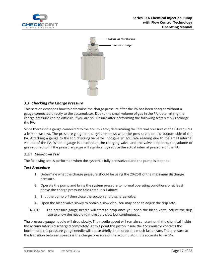
A special high pressure inflating connector is required to charge the unit (available through CheckPoint). Remove the yellow top cap. After installing the inflating connector loosen the top valve nut 3 turns. This opens the valve allowing Nitrogen to pass through. When the correct charge pressure is reached tighten the top valve nut to 55-60 in lb. Disconnect the inflating connector and reinstall the protective cap using 5-10 in lb.
NOTE: CheckPoint sells charging kits compatible with the PA. Contact your CheckPoint Distributor.
NOTE: The Accumulator may be removed from the system for charging.
3.2 Checking the PA for Leaks Over time the piston seal may wear allowing the Nitrogen to leak past the seal. If the accumulator (mounted vertically) is in a pressurized system with a leaking seal the gas will remain above the piston. Once the system pressure drops below the charge pressure the gas will escape thereby lowering the charge pressure. Additionally, the O-ring under the charge valve on top may leak if the valve loosens.
3.2.1 The quickest way to determine if the PA has lost its charge is to remove it from the system and insert a small rod in the bottom fitting. The bottom of the piston should be approx. ½” from the bottom of the large OD. If the piston is at the top of its stroke the PA has lost its charge. Consult your CheckPoint Rep for further assistance.
3.2.2 To check for leaking seals recharge the system as described in section 3.1 “Charging the PA”. Include a valve between the high pressure inflating connector and the bottle of Nitrogen. Pressurize the PA with the valve open then close the valve. The pressure should remain constant; any drop in pressure indicates a leak. Consult your CheckPoint Rep for further assistance.
Series FXA Chemical Injection Pump with Flow Control Technology
Operating Manual
CP-MAN-PRD-FXA DFC REV01 EFF. DATE 01/01/16 Page 17 of 22
3.3 Checking the Charge Pressure This section describes how to determine the charge pressure after the PA has been charged without a gauge connected directly to the accumulator. Due to the small volume of gas in the PA, determining the charge pressure can be difficult. If you are still unsure after performing the following tests simply recharge the PA.
Since there isn’t a gauge connected to the accumulator, determining the internal pressure of the PA requires a leak down test. The pressure gauge in the system shows what the pressure is on the bottom side of the PA. Attaching a gauge to the top charging valve will not give an accurate reading due to the small internal volume of the PA. When a gauge is attached to the charging valve, and the valve is opened, the volume of gas required to fill the pressure gauge will significantly reduce the actual internal pressure of the PA.
3.3.1 Leak-Down Test
The following test is performed when the system is fully pressurized and the pump is stopped.
Test Procedure
1. Determine what the charge pressure should be using the 20-25% of the maximum discharge pressure.
2. Operate the pump and bring the system pressure to normal operating conditions or at least above the charge pressure calculated in #1 above.
3. Shut the pump off then close the suction and discharge valve.
4. Open the bleed valve slowly to obtain a slow drip. You may need to adjust the drip rate.
NOTE: The pressure gauge needle will start to drop once you open the bleed valve. Adjust the drip rate to allow the needle to move very slow but continuously.
The pressure gauge needle will drop slowly. The needle speed will remain constant until the chemical inside the accumulator is discharged completely. At this point the piston inside the accumulator contacts the bottom and the pressure gauge needle will pause briefly, then drop at a much faster rate. The pressure at the transition between speeds is the charge pressure of the accumulator. It is accurate to +/- 5%.

Series FXA Chemical Injection Pump with Flow Control Technology
Operating Manual
CP-MAN-PRD-FXA DFC REV01 EFF. DATE 01/01/16 Page 18 of 22
NOTE: It may take a few attempts to determine to optimum drip rate, starting pressure and range of the gauge.
NOTE: The accuracy of the leak down test is affected by the resolution of the pressure gauge used
during the leak down test. A pressure gauge with a range too large may not show a change in needle speeds at the charge pressure. If you cannot identify the change in needle speed to indicate the charge pressure, you will need a pressure gauge with a smaller range.
NOTE: Use caution if the max rating of the pressure gauge is below the discharge pressure; your
gauge can be damaged by over pressurization
3.3.2 Start Up Test
A second method to help determine the charge pressure is performed at startup.
Test Procedure
• Start with the pump at zero discharge pressure (DP) so the accumulator has expelled all chemical and the piston has bottomed out.
• Start the pump and watch the gauge each time the pump strokes (slower stroke rates provide better results). The initial strokes of the pump start to pressurize the system.
• During this phase the needle will have large max. to min. fluctuations until the discharge pressure reaches the charge pressure. While the discharge pressure is below the charge pressure the accumulator does not respond to the pump stroking.
• When the DP equals the charge pressure the next few strokes will fill the accumulator. The pressure fluctuations will be greatly reduced since the accumulator helps maintain pressure during the suction stroke.
• The point where the needle fluctuations reduce is the charge pressure.
NOTE: This test works best with plungers having smaller ratios of “volume per stroke to internal volume of the PA”. Large plungers will fill the small accumulator quick therefore may not produce a distinct transition.
NOTE: If both tests produce unclear results recharge the unit.
4. PUMP MAINTENANCE
The CheckPoint Series FXA is designed to provide trouble-free operation for many years with little adjustment, lubrication, or other routine maintenance. However, like any other device, proper maintenance can extend the life of the product. This can include periodic cleaning of the chemical inlets, and lubrication.

Series FXA Chemical Injection Pump with Flow Control Technology
Operating Manual
CP-MAN-PRD-FXA DFC REV01 EFF. DATE 01/01/16 Page 19 of 22
4.1 Lubrication The CheckPoint Series FXA reciprocator drive contains internal rotating parts requiring constant lubrication.The housing for the drive serves as a oil reservoir and requires the oil level to be above the centerline of the plunger adapter. To facilitate the monitoring and accurate level contol of the lubricating fluid, two sight plugs are installed on the housing. Fill the FXA with oil until the “normal/low” sight is covered but no oil is present in the “high” sight. If the oil level drops below the “normal/low” sight, suspend operation until the level can be resored. The proper oil level in indicated in the figure below.
Startup The Series FXA pump is delivered with an empty reservoir. Prior to startup, fill FXA drive housing using 7 ounces (60mL) of SAE rated 5W-30 motor oil. CheckPoint recommends using Fully Synthetic oil for longer life. Before filling with oil ensure the drain plug in the bottom of housing is installed. Remove top breather vent in housing. Use a funnel to pour oil into the housing. Replace top breather vent after filling with oil. Take care not to over-tighten the connections.
4.1.1 Periodic Inspection For proper operation oil must be above the centerline of the pump. Remove the top breather vent and inspect the fluid level monthly or as conditions require. Add oil as required to maintain proper levels.
4.1.2 Oil Change CheckPoint recommends changing the drive oil every 2000 hours.
4.1.3 Cold Weather Operating the FXA in climates where temperatures fall below 20°F may require thinner oil. CheckPoint recommends using a Fully Synthetic 0W-20. For extreme low temperatures external methods to add heat prior to startup are recommended. Once in operation the FXA will produce sufficient heat to maintain oil fluidity.
Series FXA Chemical Injection Pump with Flow Control Technology
Operating Manual
CP-MAN-PRD-FXA DFC REV01 EFF. DATE 01/01/16 Page 20 of 22
NOTE: CheckPoint offers an optional breather/oil level sight glass as a replacement for the supplied top vent. As long as a supply of oil is maintained in the sight glass sufficient oil for operation is maintained.
5. TROUBLESHOOTING
5.1 Pump runs, but chemical does not discharge at the correct rate 5.1.1 Suction check valve may be clogged with debris To flush, allow pump to cycle at maximum rate for at least 60 seconds. If no improvement is noted, remove the suction check valve from body of pump. Blow the check out with air or water pressure. If the first attempts are unsuccessful, a check rebuild could be necessary.
NOTE: CheckPoint FailSafeTM check valves do not need replacement when they do not check properly. A simple rebuild kit is available to replace the O-rings, which corrects all but the most severe check problems. Corrosion of the valve seat, retainer or poppet indicates an incorrect check valve material. Please contact CheckPoint to request chemical compatibility information.
NOTE: Always replace Teflon™ tape or other appropriate thread sealant on check valve threads during reinstallation to avoid chemical leakage or the introduction of air to the chemical head.
5.1.2 Pump may have lost prime and became “air locked” Check to ensure that there are no leaks in any process lines, particularly upstream of the pump within the chemical suction lines. If air is introduced through the suction side, the pump may lose prime. Read Section 1.1.6 and its subparagraphs carefully for details. A common source of air in the supply is the block valve ahead of the suction check. Check this valve to make sure the stem packing is tight and that the materials of construction are compatible with the chemical being pumped. Also, check that the pump’s packing is not leaking. Finally, on pumps supplying chemical into gas lines, it is possible that the discharge port may be leaking. A leaky discharge port may allow gas under pressure to “back into” the chemical head.
5.1.3 Check valves may have been re-located away from the chemical head of the pump The checks must stay directly attached to the head in order to facilitate chemical movement.
5.1.4 Chemical may be obstructed from entering the pump Pumping upstream of the chemical head may allow a blockage which prevents chemical from getting to the suction check valve. A common example is an in-line chemical filter becoming clogged with debris. Solution - clean out suction plumbing and clean or replace chemical filter.
5.1.5 Chemical supply line size or configuration may cause NPSHa to drop below NPSHr.
5.1.6 Calibration gauge may be reading incorrectly due to clogged air vent If the calibration gauge is not reading correctly, it may appear chemical is not getting into the process. Check for an obstruction in the gauge or in the air vent atop the gauge.
5.1.7 Piston Accumulator has lost its precharge If the DFC in the system requires a PA check the charge in the accumulator per section 3.3. If the PA has completely lost its charge the DFC will only be able to reduce the delivery volume approximately 50% of the maximum delivery volume. Check and correct the charge as required per section 3.1“Charging the Piston Accumulator”.

Series FXA Chemical Injection Pump with Flow Control Technology
Operating Manual
CP-MAN-PRD-FXA DFC REV01 EFF. DATE 01/01/16 Page 21 of 22
5.1.8 Adjusting the DFC Does Not Change the Delivery Volume There could be several factors causing the DFC not to adjust the delivery volume. Due to the complexity of the DFC testing in the field is limited. Please contact CheckPoint to discuss your findings & repair options.
• Is the Shaft Connected to the Adjuster? Excessive force on the knob can shear the cross pin between the shaft and the adjuster. Rotate the DFC knob to the full open and closed positions. When turning the knob, a positive stop should occur in both positions. If the knob continues to turn after a full rotation the cross pin has been sheared. Consult your CheckPoint Rep.
• Is the Internal DFC Accumulator Moving Freely Close the DFC (full CCW), this drops the adjuster onto the accumulator. As the pump strokes the accumulator does not move. Open the DFC 3/4 of a turn. Slowly close the DFC (CCW) as the pump continues to stroke. You should feel some resistance every stroke when the accumulator contacts the adjuster. If no resistance is felt the accumulator is not moving. Consult your CheckPoint Rep.
DFC Doesn’t Reduce Delivery Volume Amount Specified Make sure the DFC capability is what you are expecting. If the DFC doesn’t reduce the volume specified, the PA may not be working properly. Test the charge pressure per Section 3.3 or recharge. If one is not in the system the DFC will only be able to reduce the delivery volume approximately 50% of the maximum delivery volume. Consult CheckPoint for assistance sizing the required PA.
5.2 Pump Does Not Stroke 5.2.1 Check power to motor Ensure motor has required power supplied and is turned on.
5.2.2 Motor power is too low Ensure proper motor sizing for the particular application. Contact your Authorized CheckPoint Distributor for sizing assistance.
5.2.3 Plunger adapter pin is sheared Inspect connection between plunger and plunger adapter. If plunger is disconnected from plunger adapter contact your Authorized CheckPoint Distributor.
5.2.4 Drive cam follower is damaged Contact your Authorized CheckPoint Distributor.
5.2.5 Shaft or shaft keyway is damaged Contact your Authorized CheckPoint Distributor.
5.3 Pump is Excessively Noisy 5.3.1 Drive components may be worn Motor or gear reducer may be worn. Contact your drive component manufacturer
5.3.2 FXA shaft or follower may be worn Clearances between rotating components may have increased due to wear.
NOTE: When troubleshooting for excessive noise, care must be exercised as noise may appear to come from sources other than the worn component.
5.4 Chemical Leakage from Packing 5.4.1 Packing may be worn Prior to replacing the packing, it is important to determine if wear is premature. Common causes of prematurely worn packing are:

Series FXA Chemical Injection Pump with Flow Control Technology
Operating Manual
CP-MAN-PRD-FXA DFC REV01 EFF. DATE 01/01/16 Page 22 of 22
5.4.1.1 Chemical may be attacking packing elastomer material - Remove the packing from the packing gland; if the packing has been subject to chemical attack, it will appear swollen or badly damaged. Contact CheckPoint or your Authorized CheckPoint Distributor. If the chemical has recently been changed or if the pump has just been placed in service, there is a good chance that new packing materials are required.
5.4.1.2 Chemical may be attacking plunger material - The plunger will be severely worn, pitted, or corroded when inspected.
5.4.1.3 Chemical may have abrasives suspended in it - The plunger will appear scored and the packing will appear severely worn. CheckPoint offers high performance chemical filters appropriate for Series FXA applications.
5.5 Unable to prime pump 5.5.1 DFC may not be set to full flow When priming the pump the DFC must be on “0” (full flow - CCW). If the DFC is not set to full flow during priming, the more difficult it is to prime (to the point it becomes impossible).
5.6 Other Problems
If you are experiencing an operating problem not listed above, or if none of the above troubleshooting actions solve your operating problem, please contact your Authorized CheckPoint Distributor or contact CheckPoint directly at +1 (800) 847-PUMP or +1 (504) 340-0770 or [email protected]. We will work to assist you determining appropriate next steps. Once CheckPoint has had the opportunity to help you troubleshoot your problem, please keep in mind the following regarding repairs:
5.6.1 CheckPoint offers exchange programs to keep you in serviceWe will ship you a rebuilt pump, which you will be able to install prior to sending us your existing pump. Upon receipt of your pump, we will tear it down, rebuild, and report our findings. We offer a fixed-price exchange plan, an actual-cost plan, and a consigned exchange. Please contact CheckPoint to learn more about our unique exchange services.
5.6.2 Nothing beats factory-direct repairs Although the Series FXA pump has been designed to be easy to operate and repair, the best way to ensure continued reliable service is to have your pump repaired by the factory. OEM repair services ensure CheckPoint quality and reliability.
5.6.3 Remember that after you repair your CheckPoint pump, it should perform like new If your pump is anything less than exceptional, call us to determine what can be done to restore the pump to “like-new” performance.
5.6.4 Training sessions are available CheckPoint strives to maintain excellence in all that we do & we are happy to share. If you would like to train your employees on CheckPoint Pumps & Systems, please contact us to discuss training options.


