
SERIES 7888 METER PRINTER
18
SATAM Siège Social : Paris Nord II – 5, rue des Chardonnerets Usine de Falaise – Avenue de Verdun – B.P. 129 – 14700 FALAISE – France B.P. 85012 – Tremblay- en-France – 95931 Roissy C.D.G. Cedex - France Tél. : +33 (0)2 31 41 41 41 Tél. : +33 (0)1 49 90 77 00 Fax : +33 (0)2 31 40 75 61 Fax : +33 (0)1 49 90 77 99 SIRET 495 233 124 000 17 SA au capital de 6 037 000 € – RCS Bobigny B 495 233 124 CODE APE 2813 Z SIRET 495 233 124 000 17 – Code APE 2813 Z – N° TVA : FR 48 495 233 124 SERIES 7888 METER PRINTER MANUAL DESCRIPTION - INSTALLATION - OPERATION - SERVICING U508219-e – Revision 2 – 25 February 2009 This document consists of 18 pages, including the flyleaf This document is the property of SATAM And may not transmitted to third parties without prior authorisation SATAM may modify this document without prior authorisation CONFORME à la directive européenne 94/9/CE – ATEX In conformity with the European directive 94/9/CE-ATEX
Transcript of SERIES 7888 METER PRINTER
SATAM Siège Social : Paris Nord II – 5, rue des Chardonnerets Usine de Falaise – Avenue de Verdun – B.P. 129 – 14700 FALAISE – France B.P. 85012 – Tremblay- en-France – 95931 Roissy C.D.G. Cedex - France Tél. : +33 (0)2 31 41 41 41 Tél. : +33 (0)1 49 90 77 00 Fax : +33 (0)2 31 40 75 61 Fax : +33 (0)1 49 90 77 99 SIRET 495 233 124 000 17 SA au capital de 6 037 000 € – RCS Bobigny B 495 233 124 CODE APE 2813 Z SIRET 495 233 124 000 17 – Code APE 2813 Z – N° TVA : FR 48 495 233 124
SERIES 7888 METER PRINTER
MANUAL DESCRIPTION - INSTALLATION - OPERATION -
SERVICING
U508219-e – Revision 2 – 25 February 2009
This document consists of 18 pages, including the flyleaf
This document is the property of SATAM
And may not transmitted to third parties without prior authorisation
SATAM may modify this document without prior authorisation
CONFORME à la directive européenne 94/9/CE – ATEX
In conformity with the European directive 94/9/CE-ATEX
Edition du 25/02/09 /18 U508219-e Revisi on : 2 2
Summary
SECTION 1. INTRODUCTION.......................................................................................................................... 3
A. GENERAL ..................................................................................................................................................... 3
SECTION 2. DESCRIPTION.............................................................................................................................. 4
A. OPERATION OF ZERO START PRINTER.................................................................................................. 4 B. OPERATION OF ACCUMULATIVE PRINTER.......................................................................................... 4
SECTION 3. PRINTER REMOVAL AND INSTALLATION........................................................................ 6
A. REMOVAL. ................................................................................................................................................... 6 B. INSTALLATION. .......................................................................................................................................... 6
SECTION 4. CLEANING AND LUBRICATING ............................................................................................. 7
A. GENERAL ..................................................................................................................................................... 7 B. CLEANING.................................................................................................................................................... 7 C. RECOMMENDED LUBRICATION. ............................................................................................................ 7 D. LUBRICATION POINTS .............................................................................................................................. 8
SECTION 5. TROUBLESHOOTING................................................................................................................. 9
A. GENERAL CHECKS..................................................................................................................................... 9 B. TROUBLESHOOTING. .............................................................................................................................. 12 C. TICKET POSITION ADJUSTMENT .......................................................................................................... 12 D. SALES NUMBER ADVANCING MECHANISM INSPECTION. ............................................................. 13 E. RIGHT-HAND WHEEL INCHING MECHANISM ADJUSTMENT. ........................................................ 14
SECTION 6. REPAIR AND REPLACEMENT............................................................................................... 14
A. TICKET TRAY REMOVAL........................................................................................................................ 14 B. WHEEL REMOVAL.................................................................................................................................... 15 C. WHEEL INSTALLATION. ......................................................................................................................... 15 FOR ZERO START PRINTERS............................................................................................................................... 15
FOR ACCUMUIATIVE PRINTERS................................................................................................................ 15
D. TICKETTRAYINSTALLATION................................................................................................................ 15 E. RESET GEARS REPLACEMENT AND TIMING OF PRINTER............................................................... 16
SECTION 7. INSTALLATION INSTRUCTIONS.......................................................................................... 17
FOR KITS 312020-357, -423, -675, AND -893 .................................................................................................. 17
A. INTRODUCTION........................................................................................................................................ 17 B. PARTS LIST. ............................................................................................................................................... 17 C. INSTALLATION INSTRUCTIONS............................................................................................................ 17 D. OPERATIONAL CHECK............................................................................................................................ 18

Edition du 25/02/09 /18 U508219-e Revisi on : 2 3
SECTION 1. INTRODUCTION A. GENERAL These instructions are for servicing the Series 7888 Printer Registers.
Every Meter Register is thoroughly tested at the meter factory when installed on the meter. However, like any precision mechanism, it requires periodic care to ensure maximum service. This manual is for use in areas where factory rebuilding facilities and adequate exchange stocks are not readily accessible. Where manufacturer's replacement stocks are available, it is important that no attempt be made to repair any meter register defective within the terms of the warranty as by doing so, the warranty is void and the user is deprived of the protection provided by the warranty. It is recommended that, when possible, meter registers be replaced and the defective unit returned to the meter manufacturer.
Edition du 25/02/09 /18 U508219-e Revisi on : 2 4
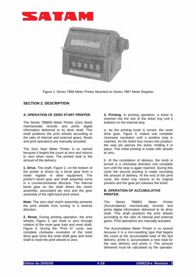
Figure 1. Series 7888 Meter Printer Mounted on Series 7887 Meter Register
SECTION 2. DESCRIPTION A. OPERATION OF ZERO START PRINTER. The Series 788800 Meter Printer (Zero Start) mechanically records and prints digital information delivered to its drive shaft. This shaft positions the print wheels according to the ratio of internal and external gears. Reset and print operations are manually actuated. The Zero Start Meter Printer is so named because it begins the count at zero and returns to zero when reset. The printed total is the amount of the delivery. 1. Drive. The shaft, Figure 2, on the bottom of the printer is driven by a bevel gear from a meter register or other equipment. The printer's bevel gear and shaft assembly turns in a counterclockwise direction. The internal bevel gear on the shaft drives the clutch assembly, associated pin ions and the gear assembly of the right-hand print wheel. Note: The zero start clutch assembly prevents the print wheels from turning in a reverse direction. 2. Reset. During printing operation, the print wheels, Figure 2, are reset to zero through rotation of the reset gear train and reset shaft, Figure 3. During the "Print ln" cycle, one complete clockwise revolution of the reset drive gear turns the reset shaft gear and reset shaft to reset the print wheels to zero.
3. Printing. ln printing operation, a ticket is inserted into the slot of the ticket tray unit it bottoms on the internal stop. a. As the printing knob is turned, the reset drive gear, Figure 3, makes one complete clockwise revolution until a positive stop is reached. As the ticket tray moves into position, the seal pin pierces the ticket, holding it in place. This initial printing is made with wheels at zero. b. At the completion of delivery, the knob is turned in a clockwise direction one complete turn until the stop is again reached. During this cycle the second printing is made recording the amount of delivery. At the end of the print cycle, the ticket tray returns to its original position and the gear pin releases the ticket. B. OPERATION OF ACCUMULATIVE PRINTER. The Series 788801 Meter Printer (Accumulative) mechanically records and prints digital information delivered to its drive shaft. This shaft positions the print wheels according to the ratio of internal and external gears. Print operations are manually actuated. The Accumulative Meter Printer is so named because it is a non-resetting type that begins the count at the accumulated total of the last delivery, prints it, accumulates a new total for the new delivery and prints it. The amount delivered must be calculated by the operator:
Edition du 25/02/09 /18 U508219-e Revisi on : 2 5
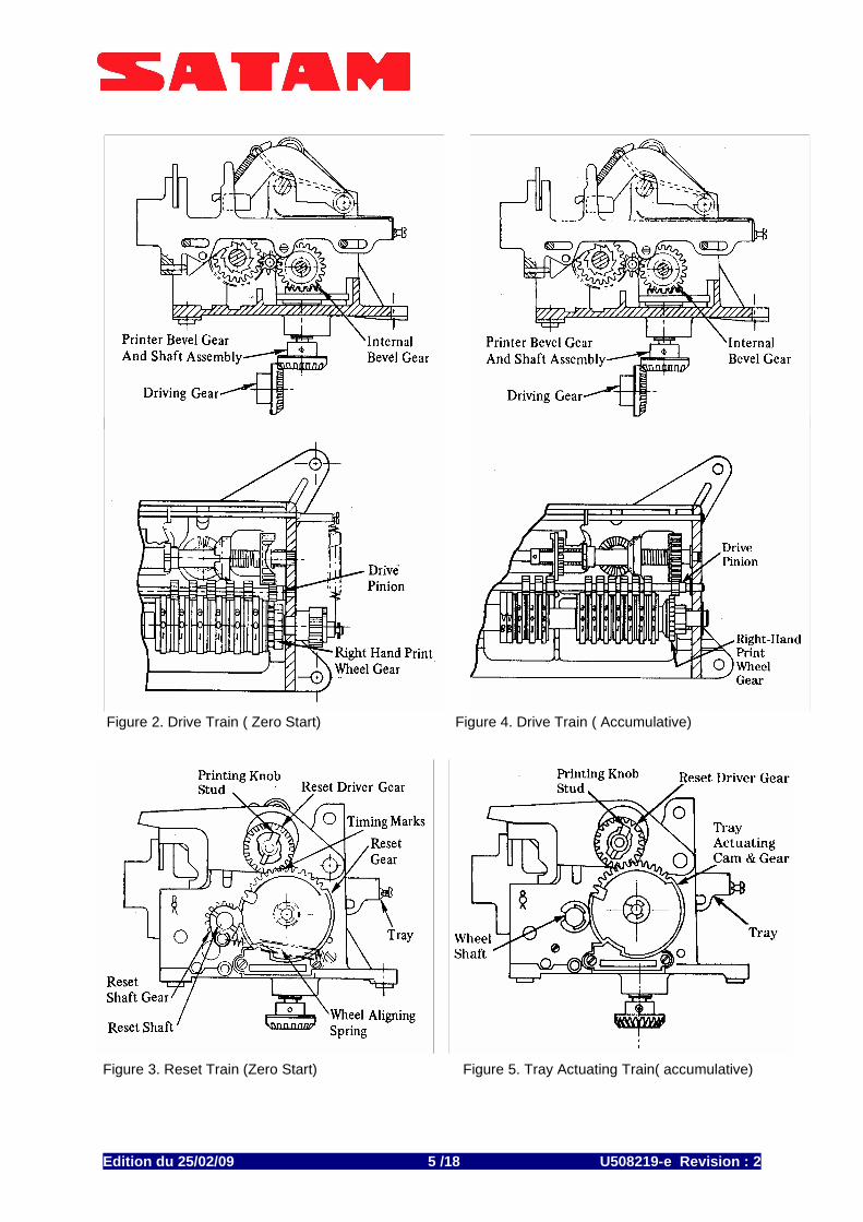
Figure 2. Drive Train ( Zero Start) Figure 4. Drive Train ( Accumulative) Figure 3. Reset Train (Zero Start) Figure 5. Tray Actuating Train( accumulative)
Edition du 25/02/09 /18 U508219-e Revisi on : 2 6
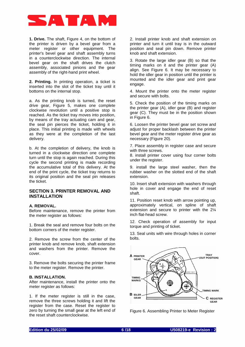
1. Drive. The shaft, Figure 4, on the bottom of the printer is driven by a bevel gear from a meter register or other equipment. The printer's bevel gear and shaft assembly turns in a counterclockwise direction. The internal bevel gear on the shaft drives the clutch assembly, associated pinions and the gear assembly of the right-hand print wheel. 2. Printing. ln printing operation, a ticket is inserted into the slot of the ticket tray until it bottoms on the internal stop. a. As the printing knob is turned, the reset drive gear, Figure 5, makes one complete clockwise revolution until a positive stop is reached. As the ticket tray moves into position, by means of the tray actuating cam and gear, the seal pin pierces the ticket, holding it in place. This initial printing is made with wheels as they were at the completion of the last delivery. b. At the completion of delivery, the knob is turned in a clockwise direction one complete turn until the stop is again reached. During this cycle the second printing is made recording the accumulative total of this delivery. At the end of the print cycle, the ticket tray returns to its original position and the seal pin releases the ticket. SECTION 3. PRINTER REMOVAL AND INSTALLATION A. REMOVAL. Before maintenance, remove the printer from the meter register as follows: 1. Break the seal and remove four bolts on the bottom corners of the meter register. 2. Remove the screw from the center of the printer knob and remove knob, shaft extension and washers from the printer. Remove the cover. 3. Remove the bolts securing the printer frame to the meter register. Remove the printer. B. INSTALLATION. After maintenance, install the printer onto the meter register as follows: 1. If the meter register is still in the case, remove the three screws holding it and lift the register from the case. Reset the register to zero by turning the small gear at the left end of the reset shaft counterclockwise.
2. Install printer knob and shaft extension on printer and turn it until tray is in the outward position and seal pin down. Remove printer knob and shaft extension. 3. Rotate the large idler gear (B) so that the timing marks on it and the printer gear (A) align. See Figure 6. It may be necessary to hold the idler gear in position until the printer is mounted and the idler gear and print gear engage. 4. Mount the printer onto the meter register and secure with bolts. 5. Check the position of the timing marks on the printer gear (A), idler gear (B) and register gear (C). They must be in the position shown in Figure 6. 6. Loosen the printer bevel gear set screw and adjust for proper backlash between the printer bevel gear and the meter register drive gear as necessary (Figure 20). 7. Place assembly in register case and secure with three screws. 8. install printer cover using four corner bolts under the register. 9. install the large steel washer, then the rubber washer on the slotted end of the shaft extension. 10. lnsert shaft extension with washers through hole in cover and engage the end of reset shaft. 11. Position reset knob with arrow pointing up, approximately vertical, on spline of shaft extension and secure to printer with the 2¼ inch flat-head screw. 12. Check operation of assembly for input torque and printing of ticket. 13. Seal units with wire through holes in corner bolts.
Figure 6. Assembling Printer to Meter Register
A PRINTER GEAR
B IDLER GEAR
TIMING MARKS
C REGISTER GEAR
TIMING MARK
TRAY (OUT POSITION)
Edition du 25/02/09 /18 U508219-e Revisi on : 2 7
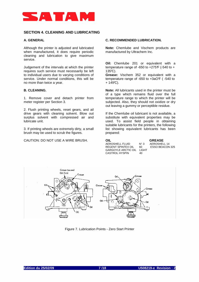
SECTION 4. CLEANING AND LUBRICATING A. GENERAL Although the printer is adjusted and lubricated when manufactured, it does require periodic cleaning and lubrication to give maximum service. Judgement of the intervals at which the printer requires such service must necessarily be left to individual users due to varying conditions of service. Under normal conditions, this will be no more than twice a year. B. CLEANING. 1. Remove cover and detach printer from meter register per Section 3. 2. Flush printing wheels, reset gears, and ail drive gears with cleaning solvent. Blow out surplus solvent with compressed air and lubricate unit. 3. If printing wheels are extremely dirty, a small brush may be used to scrub the figures. CAUTION: DO NOT USE A WIRE BRUSH.
C. RECOMMENDED LUBRICATION. Note: Chemlube and Vischem products are manufactured by Ultrachem Inc. Oil: Chemlube 201 or equivalent with a temperature range of -650 to +275°F (-540 to + 135°C). Grease: Vischem 352 or equivalent with a temperature range of -650 to +3aO°F ( -540 to + 149°C). Note: All lubricants used in the printer must be of a type which remains fluid over the full temperature range to which the printer will be subjected. Also, they should not oxidize or dry out leaving a gummy or perceptible residue. If the Chemlube oil lubricant is not available, a substitute with equivalent properties may be used. To assist field people in obtaining suitable lubricants for the printers, the following list showing equivalent lubricants has been prepared: OIL GREASE AEROSHELL FLUID N°. 3 AEROSHELL 14 REGENT SPINTEX OIL 60 ESSO BEACON 325 GARGOYLE ARCTIC OIL LIGHT CASTROL HYSPIN 40
Figure 7. Lubrication Points - Zero Start Printer
Edition du 25/02/09 /18 U508219-e Revisi on : 2 8
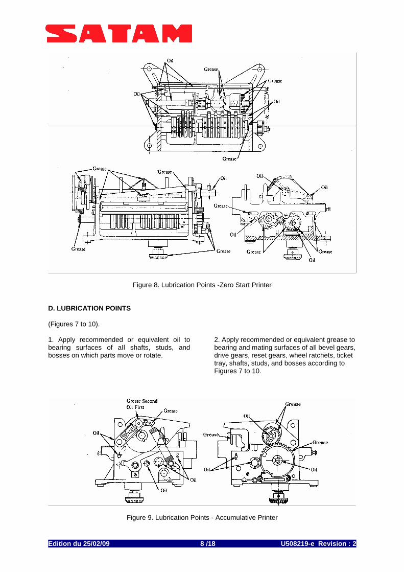
Figure 8. Lubrication Points -Zero Start Printer D. LUBRICATION POINTS (Figures 7 to 10). 1. Apply recommended or equivalent oil to bearing surfaces of aIl shafts, studs, and bosses on which parts move or rotate.
2. Apply recommended or equivalent grease to bearing and mating surfaces of aIl bevel gears, drive gears, reset gears, wheel ratchets, ticket tray, shafts, studs, and bosses according to Figures 7 to 10.
Figure 9. Lubrication Points - Accumulative Printer
Edition du 25/02/09 /18 U508219-e Revisi on : 2 9
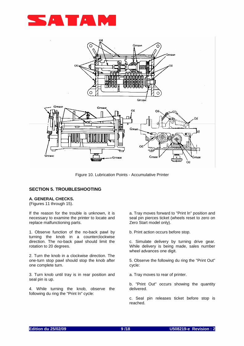
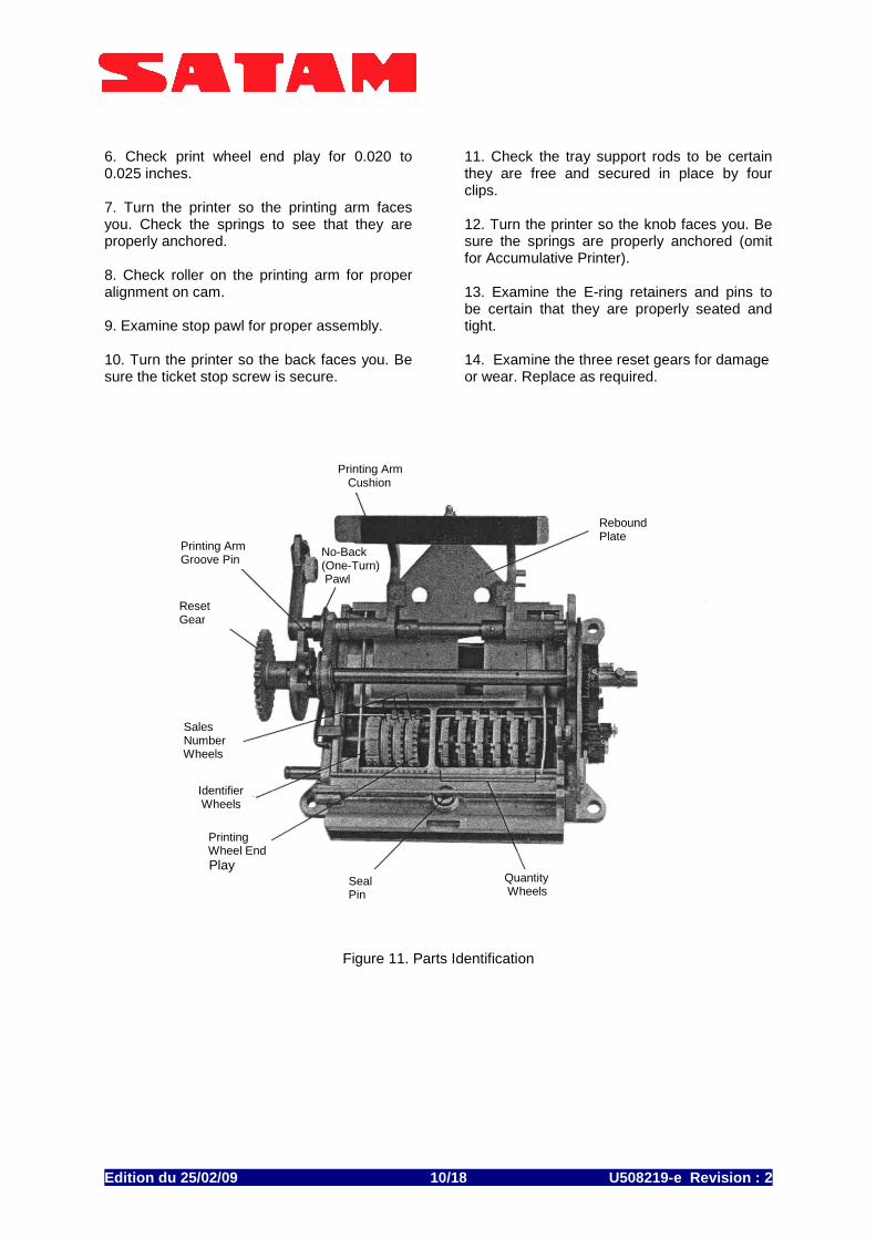
Figure 10. Lubrication Points - Accumulative Printer SECTION 5. TROUBLESHOOTING A. GENERAL CHECKS. (Figures 11 through 15). If the reason for the trouble is unknown, it is necessary to examine the printer to locate and replace malfunctioning parts. 1. Observe function of the no-back pawl by turning the knob in a counterclockwise direction. The no-back pawl should limit the rotation to 20 degrees. 2. Turn the knob in a clockwise direction. The one-turn stop pawl should stop the knob after one complete turn. 3. Turn knob until tray is in rear position and seal pin is up. 4. While turning the knob, observe the following du ring the "Print ln" cycle:
a. Tray moves forward to "Print ln" position and seal pin pierces ticket (wheels reset to zero on Zero Start model only). b. Print action occurs before stop. c. Simulate delivery by turning drive gear. While delivery is being made, sales number wheel advances one digit. 5. Observe the following du ring the "Print Out" cycle: a. Tray moves to rear of printer. b. "Print Out" occurs showing the quantity delivered. c. SeaI pin releases ticket before stop is reached.
Edition du 25/02/09 /18 U508219-e Revisi on : 2 10
6. Check print wheel end play for 0.020 to 0.025 inches. 7. Turn the printer so the printing arm faces you. Check the springs to see that they are properly anchored. 8. Check roller on the printing arm for proper alignment on cam. 9. Examine stop pawl for proper assembly. 10. Turn the printer so the back faces you. Be sure the ticket stop screw is secure.
11. Check the tray support rods to be certain they are free and secured in place by four clips. 12. Turn the printer so the knob faces you. Be sure the springs are properly anchored (omit for Accumulative Printer). 13. Examine the E-ring retainers and pins to be certain that they are properly seated and tight. 14. Examine the three reset gears for damage or wear. Replace as required.
Figure 11. Parts Identification
Printing Arm Cushion
Rebound Plate
Printing Arm Groove Pin
Reset Gear
Identifier Wheels
Printing Wheel End Play
Sales Number Wheels
Quantity Wheels
Seal Pin
No-Back (One-Turn) Pawl
Edition du 25/02/09 /18 U508219-e Revisi on : 2 11
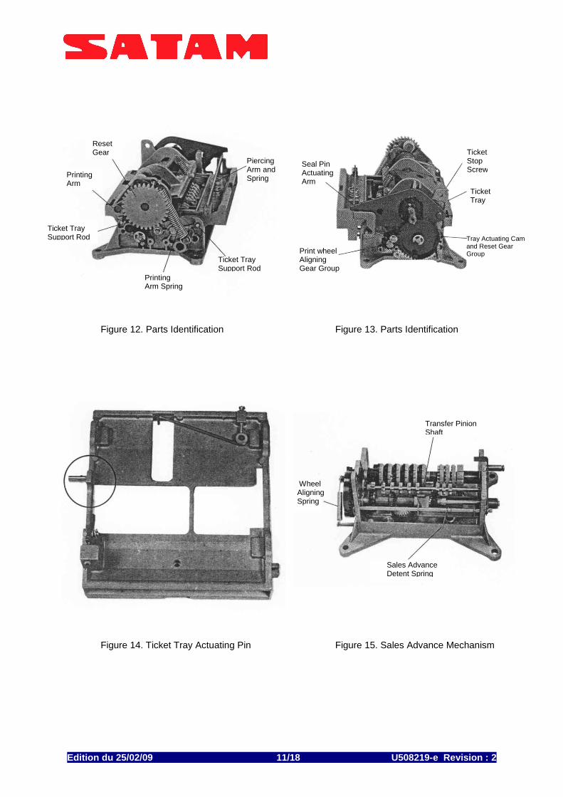
Figure 12. Parts Identification Figure 13. Parts Identification
Figure 14. Ticket Tray Actuating Pin Figure 15. Sales Advance Mechanism
Reset Gear
Printing Arm
Ticket Tray Support Rod
Piercing Arm and Spring
Ticket Tray Support Rod
Printing Arm Spring
Seal Pin Actuating Arm
Print wheel Aligning Gear Group
Tray Actuating Cam and Reset Gear Group
Ticket Tray
Ticket Stop Screw
Wheel Aligning Spring
Transfer Pinion Shaft
Sales Advance Detent Spring
Edition du 25/02/09 /18 U508219-e Revisi on : 2 12
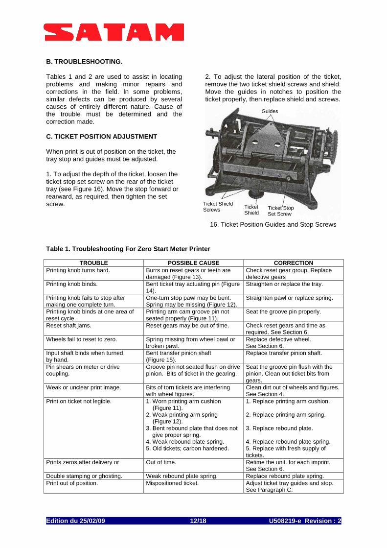
B. TROUBLESHOOTING. Tables 1 and 2 are used to assist in locating problems and making minor repairs and corrections in the field. ln some problems, similar defects can be produced by several causes of entirely different nature. Cause of the trouble must be determined and the correction made. C. TICKET POSITION ADJUSTMENT When print is out of position on the ticket, the tray stop and guides must be adjusted. 1. To adjust the depth of the ticket, loosen the ticket stop set screw on the rear of the ticket tray (see Figure 16). Move the stop forward or rearward, as required, then tighten the set screw.
2. To adjust the lateral position of the ticket, remove the two ticket shield screws and shield. Move the guides in notches to position the ticket properly, then replace shield and screws.
16. Ticket Position Guides and Stop Screws
Table 1. Troubleshooting For Zero Start Meter Printer
TROUBLE POSSIBLE CAUSE CORRECTION Printing knob turns hard. Burrs on reset gears or teeth are
damaged (Figure 13). Check reset gear group. Replace defective gears
Printing knob binds. Bent ticket tray actuating pin (Figure 14).
Straighten or replace the tray.
Printing knob fails to stop after making one complete turn.
One-turn stop pawl may be bent. Spring may be missing (Figure 12).
Straighten pawl or replace spring.
Printing knob binds at one area of reset cycle.
Printing arm cam groove pin not seated properly (Figure 11).
Seat the groove pin properly.
Reset shaft jams. Reset gears may be out of time. Check reset gears and time as required. See Section 6.
Wheels fail to reset to zero. Spring missing from wheel pawl or broken pawl.
Replace defective wheel. See Section 6.
Input shaft binds when turned by hand.
Bent transfer pinion shaft (Figure 15).
Replace transfer pinion shaft.
Pin shears on meter or drive coupling.
Groove pin not seated flush on drive pinion. Bits of ticket in the gearing.
Seat the groove pin flush with the pinion. Clean out ticket bits from gears.
Weak or unclear print image. Bits of torn tickets are interfering with wheel figures.
Clean dirt out of wheels and figures. See Section 4.
Print on ticket not legible. 1. Worn printing arm cushion (Figure 11). 2. Weak printing arm spring (Figure 12). 3. Bent rebound plate that does not
give proper spring. 4. Weak rebound plate spring. 5. Old tickets; carbon hardened.
1. Replace printing arm cushion. 2. Replace printing arm spring. 3. Replace rebound plate. 4. Replace rebound plate spring. 5. Replace with fresh supply of tickets.
Prints zeros after delivery or Out of time. Retime the unit. for each imprint. See Section 6.
Double stamping or ghosting. Weak rebound plate spring. Replace rebound plate spring. Print out of position. Mispositioned ticket. Adjust ticket tray guides and stop.
See Paragraph C.
Guides
Ticket Shield Screws Ticket
Shield Ticket Stop Set Screw

Edition du 25/02/09 /18 U508219-e Revisi on : 2 13
D. SALES NUMBER ADVANCING MECHANISM INSPECTION. 1. Sales number advancing mechanism, Figure 17, is tripped when printing occurs. The movement of the sale advance wheel starts immediately with rotation of the input shaft and completes transfer within 1/4 of a revolution. If the sales number on the right-hand wheel does not align properly with the other wheel, it must be adjusted. 2. To align the wheel, position the tail of the clutch spring in different slots of the transfer disc until properly adjusted.
Figure 17. Adjusting Sales Number Advancing
Mechanism Table 2. Troubleshooting For Accumulative Meter Printer
TROUBLE POSSIBLE CAUSE CORRECTION Printing knob turns bard. Burrs on reset gears or teeth are
damaged (Figure 13). Check reset gear group. Replace defective gears.
Printing knob binds. Bent ticket tray actuating pin (Figure 14).
Straighten or replace the tray.
Printing knob fails to stop alter making one complete turn.
One-turn stop pawl may be bent. Spring may be missing (Figure 12).
Straighten pawl or replace spring.
Printing knob binds at one area of reset cycle.
Printing arm cam groove pin not seated properly (Figure 11).
Seat the groove pin properly.
Reset shaft jams. Reset gears may be out of time. Check reset gears and time as required. See Section 6.
Right-hand numbers not aligned with middle numbers
Right-hand wheel inching mechanism not adjusted properly (Figure 18).
Adjust inching mechanism. See Paragraph E.
Input shaft binds when turned by band.
Bent transfer pinion shaft (Figure 15).
Replace transfer pinion shaft.
Pin shears on meter or drive coupling.
Groove pin not seated flush on drive pinion. Bits of ticket in the gearing.
Seat the groove pin flush with the pinion. Clean out ticket bits from gears.
Weak or unclear print image. Bits of torn tickets are interfering with wheel figures.
Clean dirt out of wheels and figures. See Section 4.
Print on ticket not legible. 1. Worn printing arm cushion (Figure 11). 2. Weak printing arm spring (Figure 12). 3. Bent rebound plate that does not give proper spring. 4. Weak rebound plate spring. 5. Old tickets; carbon hardened
1. Replace printing arm cushion. 2. Replace printing arm spring. 3. Replace rebound plate. 4. Replace rebound plate spring. 5. Replace with fresh supply of tickets.
Double stamping or ghosting. Weak rebound plate spring. Replace rebound plate spring. Print out of position. Mispositioned ticket. Adjust ticket tray guides and stop.
See Paragraph C.
Clutch Spring Advancing Mechanism Transfer Disc
Edition du 25/02/09 /18 U508219-e Revisi on : 2 14
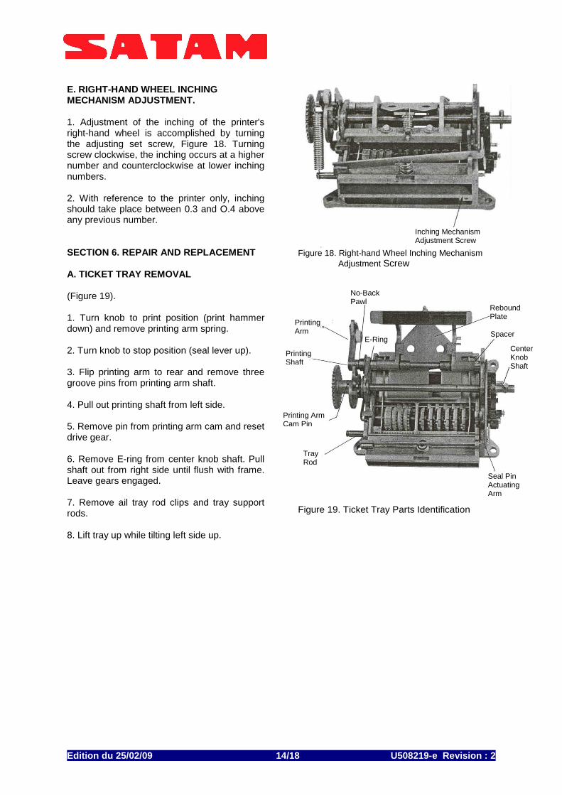
E. RIGHT-HAND WHEEL INCHING MECHANISM ADJUSTMENT. 1. Adjustment of the inching of the printer's right-hand wheel is accomplished by turning the adjusting set screw, Figure 18. Turning screw clockwise, the inching occurs at a higher number and counterclockwise at lower inching numbers. 2. With reference to the printer only, inching should take place between 0.3 and O.4 above any previous number. SECTION 6. REPAIR AND REPLACEMENT A. TICKET TRAY REMOVAL (Figure 19). 1. Turn knob to print position (print hammer down) and remove printing arm spring. 2. Turn knob to stop position (seal lever up). 3. Flip printing arm to rear and remove three groove pins from printing arm shaft. 4. Pull out printing shaft from left side. 5. Remove pin from printing arm cam and reset drive gear. 6. Remove E-ring from center knob shaft. Pull shaft out from right side until flush with frame. Leave gears engaged. 7. Remove ail tray rod clips and tray support rods. 8. Lift tray up while tilting left side up.
Figure 18. Right-hand Wheel Inching Mechanism
Adjustment Screw
Figure 19. Ticket Tray Parts Identification
Inching Mechanism Adjustment Screw
No-Back Pawl
Printing Arm
Printing Shaft
Printing Arm Cam Pin
Tray Rod
E-Ring Spacer
Rebound Plate
Center Knob Shaft
Seal Pin Actuating Arm
Edition du 25/02/09 /18 U508219-e Revisi on : 2 15
B. WHEEL REMOVAL.
1. Remove ticket tray (See Paragraph A). 2. Remove retaining ring and washer from wheel shaft (left side). 3. Remove wheel aligning spring from wheel shaft (right side) (See Figure 3). 4. Pull wheel shaft out from right side. Note: The shaft must be pulled out slowly so wheels, bushing and washers may be removed individually without damage to the printing wheels. C. WHEEL INSTALLATION. For Zero Start Printers 1. Start wheel shaft through frame (right side) and install two washers inside next to frame.
Note: When starting shaft through frame, keep spline facing out to front.
2. Place the right wheel and ratchet assembly on the shaft. Note: Wheel should be installed with zero in up position. This can be checked by moving stamping pad down over wheel to see that figure is centered in pad.
3. Move transfer pin ion over to right and mesh with right-hand wheel.
4. Move shaft to left and install next wheel on shaft, then place next transfer pinion into position.
5. Continue to place wheels and transfer pinions on the shaft until ail quantity wheels are in place. Note: Make certain that teeth of transfer pinions line up; that is, aIl short teeth must line up and all long teeth must line up.
6. After quantity wheels are in place, place washers and short spacers on shaft. The sale number wheels are then added, engaging their drive pin ions. Add identifier wheels.
7. Install long spacer and check end play: 0.020 to 0.025 inches.
8. Place washer on wheel shaft (outside of frame) and install retaining E-ring. For AccumuIative Printers
9. Start wheel shaft through frame (right side) and install one washer inside next to frame.
10. Place the ratchet assembly, drive coupling and right wheel on the shaft. Note: Wheel should be installed with zero in up position. This can be checked by moving stamping pad down over wheel to see that figure is centered in pad.
11. Move transfer pinion over to right and mesh with right-hand wheel.
12. Move shaft to left and install next wheel on shaft, then place next transfer pinion into position.
13. Continue to place wheels and transfer pinions on the shaft until all quantity wheels are in place. Note: Make certain that teeth of transfer pinions line up; that is, all short teeth must line up and all long teeth must line up.
14. After quantity wheels are in place, place washers and short spacers on shaft. The sales number wheels are then added, engaging their drive pinions. Add identifier wheels.
15. Install long spacer and check end play: 0.020 to 0.025 inches.
16. Place washer on wheel shaft (outside of frame) and install retaining E-ring. D. TICKETTRAYINSTALLATION (Figure 19). 1. Place tray inside, frame tilting right side down to allow tray stud to pass through opening in frame (right side). Be sure that tray stud enters internal groove of actuating cam.
2. Install tray support rods. Double groove must be at right in front position and at left in rear position.
3. Push center knob shaft in, keeping two washers between retaining ring groove and frame. Check timing of gears (see Paragraph E).
Edition du 25/02/09 /18 U508219-e Revisi on : 2 16
4. Install E-ring and place two washers on shaft outside the frame, small diameter washer next to frame. 5. Place and pin printing cam on shaft, keeping cam cliff in upper rear position with head of printing knob stud up. Assemble and pin reset drive gear, timing mark down. 6. Place no-back pawl and two washers on printing shaft and start shaft through frame (left side), placing spacer, platen, rebound plate, and spacer between frames. 7. Start shaft through hole in right side. Assemble piercing arm and spring to ticket tray. Assemble seal pin actuating arm, which should still be in place, over piercing arm and onto printing shaft. 8. Pin rebound plate and spacer to printing shaft. 9. Adjust the position of the print on the ticket. See Ticket Position Adjustment, Section 5. E. RESET GEARS REPLACEMENT AND TIMING OF PRINTER (See Figure 3 for parts identification.) 1. Remove E-ring and washer and spring from reset shaft gear. 2. Remove E-ring and washer from reset gear. 3. Remove roll pin from reset shaft gear. 4. Remove reset gear. 5. Remove center knob shaft per Section 6, Paragraph A, steps 5 and 6, and pull shaft from frame. 6. Remove reset drive gear. 7. Assemble new reset drive gear onto shaft and start shaft through hole in right side. Assemble piercing arm and spring to ticket tray. Assemble seal pin actuating arm, which should still be in place, over piercing arm and onto printing shaft. Note: Timing mark on gear must be down in relation to the head of the printing knob stud. 8. Install center knob shaft per Section 6, Paragraph D, steps 3, 4 and 5.
9. Hold tray in rear position and install reset gear on stud. Note: Timing mark on small reset drive gear must mesh between the two timing marks on the large reset gear. 10. To check internal cam engagement with tray stud, rotate reset gear two revolutions, noting tray movement. 11. Install washer and E-ring on reset gear stud. 12. With timing marks aligned, install reset shaft gear on shaft and secure with roll pin. Note: Roll pin must be flush with gear teeth. 13. Install wheel aligning spring, washer and E-ring.
Edition du 25/02/09 /18 U508219-e Revisi on : 2 17
SECTION 7. INSTALLATION INSTRUCTIONS FOR KITS 312020-357, -423, -675, AND -893 A. INTRODUCTION.
Each kit contains aIl parts necessary for installation of a Series 7888 Ticket Printer on a Series 7887 Meter Register. B. PARTS LIST.
Check the kit contents against the parts list to ensure that ail parts are included REFERENCE DESIGNATION Q 44602-005 Seal 1 11853-285 Seal wire 1 74800-181 Washer, knob (steel) 1 74800-125 Washer knob ( rubber) 1 324757-001 Knob, Printer Reset 1 502300-108 Screw 1 502300-109 Screw (for –893 only) 1 503641-005 Screw 4 510003-006 Lockwasher 4 325894-001 Plug, Reset Shaft Security 1 324718-001 Cover, Reset Knob hole 1 502721-001 Screw 3 510002-001 Lockwasher 3 76124-005 Gasket, Reset Knob hole 1 403071-420 Gear, Large Idler 1 511800-106 Retaining Ring 1 885008-789 Washer 4 885005-791 Washer 4 885005-937 Washer, Spring 1 251322 Manual, Instruction 1 328741-001 Shaft Extension (right side) 1 328741-002 Shaft Ext. (left side) (for 893 only) 1
C. INSTALLATION INSTRUCTIONS. 1. Remove the four corner bolts with Iockwashers from the bottom of the meter register. Remove the cover. 2. Unscrew the meter register reset knob. 3. Remove the meter register reset knob flange mounting screws and flange. 4. Remove the three hex screws that secure the meter register frame to the bottom of the case. 5. Remove the meter register frame from the case. 6. Install the reset knob hole cover and gasket with three 10-24 x 3/8 inch roundhead screws and Iockwashers.
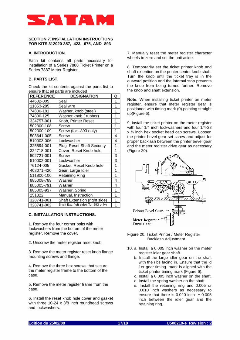
7. Manually reset the meter register character wheels to zero and set the unit aside. 8. TemporariIy set the ticket printer knob and shaft extention on the printer center knob shaft. Turn the knob until the ticket tray is in the outward position and the internal stop prevents the knob from being turned further. Remove the knob and shaft extension. Note: When installing ticket printer on meter register, ensure that meter register gear is positioned with timing mark (0) pointing straight up(Figure 6). 9. install the ticket printer on the meter register with four 1/4 inch Iockwashers and four 1/4-28 x ¾ inch hex socket head cap screws. Loosen the printer bevel gear set screw and adjust for proper backlash between the printer bevel gear and the meter register drive gear as necessary (Figure 20).
Figure 20. Ticket Printer / Meter Register
Backlash Adjustment. 10. a. Install a 0.005 inch washer on the meter
register idler gear shaft. b. Install the large idler gear on the shaft
with the ribs facing in. Ensure that the id 1er gear timing mark is aligned with the ticket printer timing mark (Figure 6).
c. Install a 0.005 inch washer on the shaft. d. Install the spring washer on the shaft.
e. Install the retaining ring and 0.005 or 0.010 inch washers as necessary to ensure that there is 0.020 inch ± 0.005 inch between the idler gear and the retaining ring.
Edition du 25/02/09 /18 U508219-e Revisi on : 2 18
11. Install the plastic security cap on the end of the meter register reset idler gear shaft. 12. Install the meter register /ticket printer assembly in the case and secure with the three hex screws removed earlier. 13. Install the ticket printer cover with the four corner bolts removed earlier. 14. Install the large steel washer, then the rubber washer on the slotted end of the shaft extension.
15. Insert shaft extension with washers thru hole in cover and engage the end of knob shaft. 16. Position reset knob with arrow pointing up, approximately vertical, on spline of shaft extension and secure to printer with the 2¼ inch flat-head screw for right- hand reset or use the 1¾ inch flat-head screw for left-hand reset.
D. OPERATIONAL CHECK. Perform the following to ensure that the meter register/ticket printer assembly is ready for service. 1. Lift the ticket slot cover and insert a ticket as far as it will go. If the ticket will not enter the tray, turn the ticket printer knob one complete revolution until the internal stop is reached. This lifts the sealing pin and permits insertion of the ticket. 2. Turn the ticket printer knob one complete turn (clockwise for right-hand reset or counter clockwise for left-hand reset) until the internal stop is reached, leaving the knob arrow pointing up.
3. Simulate a delivery by manually turning the meter register drive shaft clockwise. Make sure that the character wheels advance smoothly without binding. 4. After completing the simulated delivery, turn the ticket printer knob one complete revolution until the internal stop is reached. 5. Withdraw the ticket and check for the
following: a. Your Sale No. must be one digit higher than Previous Sale No. b. Gallon Reading -Finish minus Gallon Reading - must equal the simulated delivery shown on the meter register.