
Series 400 6076 Diesel Engines Serial Number (500000- ) · Series 400 6076 Diesel Engines Serial...
456
Series 400 6076 Diesel Engines Serial Number (500000- ) COMPONENT TECHNICAL MANUAL pÉêáÉë=QMM=SMTS=aáÉëÉä=båÖáåÉë=pÉêá~ä kìãÄÉê=ERMMMMMJ=F `qjQO=EOQj^oVRF=====båÖäáëÜ Deere Power Systems Group CTM42 (24MAR95) LITHO IN U.S.A. ENGLISH D C T CTM4 2 2 4MAR9 5
Transcript of Series 400 6076 Diesel Engines Serial Number (500000- ) · Series 400 6076 Diesel Engines Serial...

Series 4006076
Diesel EnginesSerial Number
(500000- )
COMPONENT TECHNICAL MANUALpÉêáÉë=QMM=SMTS=aáÉëÉä=båÖáåÉë=pÉêá~ä
kìãÄÉê=ERMMMMMJ=F
`qjQO=EOQj^oVRF=====båÖäáëÜ
Deere Power Systems GroupCTM42 (24MAR95)
LITHO IN U.S.A.
ENGLISH
DC
TC
TM
42
24
MA
R9
5

FOREWORD
This manual is written for an experienced technician.Essential tools required in performing certain servicework are identified in this manual and arerecommended for use.
Live with safety: Read the safety messages in theintroduction of this manual and the cautionspresented throughout the text of the manual.
N This is the safety-alert symbol. When you seethis symbol on the machine or in this manual,be alert to the potential for personal injury.
Use this component technical manual in conjunctionwith the machine technical manual. An applicationlisting in the introduction identifiesproduct-model/component type-model relationship.See the machine technical manual for information oncomponent removal and installation, and gainingaccess to the components.
This manual is divided in two parts: repair andoperation and tests. Repair sections contain
necessary instructions to repair the component.Operation and tests sections help you identify themajority of routine failures quickly.
Information is organized in groups for the variouscomponents requiring service instruction. At thebeginning of each group are summary listings of allapplicable essential tools, service equipment andtools, other materials needed to do the job, serviceparts kits, specifications, wear tolerances, and torquevalues.
Component Technical Manuals are concise serviceguides for specific components. Component technicalmanuals are written as stand-alone manuals coveringmultiple machine applications.
Fundamental service information is available fromother sources covering basic theory of operation,fundamentals of troubleshooting, generalmaintenance, and basic type of failures and theircauses.
DX,CTMIFC -19-22MAY92
Introduction
CTM42 (24MAR95) 6076 Diesel Engines—S.N. (500000— )160101
PN=3


JOHN DEERE DEALERS
IMPORTANT: The changes listed below make yourcurrent CTM obsolete. DiscardCTM42, dated 02 NOV 92. Pleasecopy this page and route throughyour service department.
• Engine application charts updated to include thelatest product models. See ENGINE APPLICATIONCHART in Group 01.
• Engine coolant information revised. See ENGINECOOLANT RECOMMENDATIONS in Group 02.
• Recommendation to use ONLY JDG23 Lifting Slingand Deere provided lifting straps for lifting engines.Also recommend the use of SAE Grade 8 or highergrade cap screws and Loctite 242 when installingengine lifting straps added to Group 03.
• New “TORQUE-TO-YIELD” instructions for tighteningcylinder head cap screws marked “SPECIAL” addedto Group 05.
• Valve lift specifications revised in Group 05 andGroup 16.
• Piston ring end gap specifications for new pistonshave been added to Group 10.
• A revised (longer) JDG681A Tap for cleaningdeeper tapped cylinder head cap screw holes in blockadded to Group 10.
• Use of JDG796 Alignment Tool for installingcrankshaft rear oil seal housing added to Group 15.
• Detailed instructions for inspection of the vibrationdamper and the crankshaft dowel pin added to Group15.
• Timing gear cover and rear oil seal housingreplacement procedures for 6076HRW33, 34, and 35Engines (equipped with structural front frame/oilsump), with engine installed in vehicle added toGroup 15.
• Camshaft lobe lift specifications and valve liftspecifications revised in Group 16.
• Recommendation against disassembly of the engineoil pump added to Group 20.
• Instructions for installation of structural frontframe/oil sump on engines used in 8000 seriestractors added to Group 20.
• Information and specifications for fan drive assemblywith press-fit fan spacer added to Group 25.
• Torque specifications for turbocharger oil inlet lineadded to Group 30.
• Information to help identify A-Series and P-Seriesfuel injection pumps and fuel supply pumps added toGroup 35.
• Instructions for disassembly and assembly of thefuel check valve deleted from Group 35. The checkvalve has been replaced by a non-serviceableassembly.
• In Group 100 — Engine Tune-Up and Break-In, theparagraph titled ALTITUDE COMPENSATIONGUIDELINE changed to EFFECTS OFTEMPERATURE AND ALTITUDE ON ENGINEPERFORMANCE.
• In Group 105, the recommended temperatures andengine speeds for checking engine oil pressurerevised. The procedure to pressure test the coolingsystem and radiator cap also revised.
• Dynamic timing procedure using TIME TRAC®
timing kit to accurately check and adjust (rotary)injection pump-to-engine timing added to Group 115.
• Instructions and specifications for check andadjustment of the fuel shut-off solenoid added toGroup 115.
• Instructions for changing 6076 generator setengines with mechanical governor from rated speedof 1800 RPM (60 Hz) to 1500 RPM (50 Hz) added toGroup 115.
TIME TRAC® is a registered trademark of Stanadyne Automotive Corp. RG,CTM42,DPS -19-21MAR95
Dealer Presentation Sheet
CTM42 (24MAR95) 6076 Diesel Engines—S.N. (500000— )160101
PN=4

ABOUT THIS MANUAL
This component technical manual covers therecommended repair procedure for 6076, 7.6 L (466cu. in.) diesel engines produced in Waterloo, Iowabeginning with Engine Serial No. (500000— ).
Before beginning repair of an engine, clean theengine and mount on a repair stand. (See Group 03 -Engine Mounting.)
Direction of engine crankshaft rotation in this manualis referenced facing the flywheel looking toward thefan. Front of engine is fan drive end.
Some components of this engine may be servicedwithout removing the engine from the machine. Referto the specific machine technical manuals forinformation on components that can be servicedwithout removing the engine from the machine andfor engine removal and installation procedures.
Read each module completely before performing anyservice.
RG,CTM42,G0,1 -19-14FEB95
CTM42 (24MAR95) 6076 Diesel Engines—S.N. (500000— )160101
PN=5

Page
Group 00—SafetySafety . . . . . . . . . . . . . . . . . . . . . . . . . . . 00-1
Group 01—General InformationUnified Inch Bolt and Cap Screw Torque
Values . . . . . . . . . . . . . . . . . . . . . . . . . 01-1Metric Bolt and Cap Screw Torque
Values . . . . . . . . . . . . . . . . . . . . . . . . . 01-2Engine Model Designation . . . . . . . . . . . . . . 01-3Engine Serial Number Plate Information . . . . . 01-4Engine Application Chart . . . . . . . . . . . . . . . 01-5Engine Application Chart . . . . . . . . . . . . . . . 01-6
Group 02—Fuels, Lubricants, and CoolantDiesel Fuel . . . . . . . . . . . . . . . . . . . . . . . . 02-1Lubricity of Diesel Fuels . . . . . . . . . . . . . . . 02-1Engine Break-In Oil . . . . . . . . . . . . . . . . . . 02-2Engine Oil . . . . . . . . . . . . . . . . . . . . . . . . 02-3Oilscan and Coolscan . . . . . . . . . . . . . . . . . 02-4Grease . . . . . . . . . . . . . . . . . . . . . . . . . . . 02-4Alternative and Synthetic Lubricants . . . . . . . 02-5Engine Coolant Requirements . . . . . . . . . . . 02-5Recommended Engine Coolant . . . . . . . . . . . 02-7Engine Coolant Specifications . . . . . . . . . . . 02-8Replenish Supplemental Coolant
Additives Between Coolant Changes . . . . 02-10Operating in Tropical Conditions . . . . . . . . . 02-11Flush and Service Cooling System . . . . . . . 02-12Disposing of Coolant . . . . . . . . . . . . . . . . 02-13
Group 03—Engine MountingEngine Repair Stand . . . . . . . . . . . . . . . . . 03-1Safety Precautions . . . . . . . . . . . . . . . . . . . 03-2Install 400 Series Adapters on Repair
Stand . . . . . . . . . . . . . . . . . . . . . . . . . . 03-2Engine Lifting Procedure . . . . . . . . . . . . . . . 03-3Clean Engine . . . . . . . . . . . . . . . . . . . . . . 03-4Disconnect Turbocharger Oil Inlet Line . . . . . 03-4Mount Engine On Repair Stand . . . . . . . . . . 03-5
Page
Group 04—Engine Rebuild Guide6076 Engine Disassembly Sequence . . . . . . . 04-1Sealant Application Guidelines . . . . . . . . . . . 04-26076 Engine Assembly Sequence . . . . . . . . . 04-4
Group 05—Cylinder Head and ValvesSpecial or Essential Tools . . . . . . . . . . . . . . 05-1Service Equipment and Tools . . . . . . . . . . . . 05-3Other Material . . . . . . . . . . . . . . . . . . . . . . 05-4Cylinder Head and Valves Specifications . . . . 05-5Check and Adjust Valve Clearance . . . . . . . . 05-7Check Valve Lift . . . . . . . . . . . . . . . . . . . . 05-9Remove Cylinder Head . . . . . . . . . . . . . . . 05-10Disassemble and Inspect Rocker Arm
Shaft Assembly . . . . . . . . . . . . . . . . . . 05-12Assemble Rocker Arm Shaft Assembly . . . . 05-14Measure Valve Recess . . . . . . . . . . . . . . . 05-14Preliminary Cylinder Head and Valve
Checks . . . . . . . . . . . . . . . . . . . . . . . . 05-15Remove Valve Assembly . . . . . . . . . . . . . . 05-16Inspect and Measure Valve Springs . . . . . . 05-17Inspect Valve Rotators and Wear Caps . . . . 05-17Clean Valves . . . . . . . . . . . . . . . . . . . . . . 05-18Inspect and Measure Valves . . . . . . . . . . . 05-18Grind Valves . . . . . . . . . . . . . . . . . . . . . . 05-19Inspect and Clean Cylinder Head . . . . . . . . 05-19Check Cylinder Head Combustion Face
Flatness . . . . . . . . . . . . . . . . . . . . . . . 05-20Measure Cylinder Head Thickness . . . . . . . 05-21Clean Valve Guides . . . . . . . . . . . . . . . . . 05-22Measure Valve Guides . . . . . . . . . . . . . . . 05-22Knurl Valve Guides . . . . . . . . . . . . . . . . . 05-23Clean and Inspect Valve Seats . . . . . . . . . 05-23Measure Valve Seats . . . . . . . . . . . . . . . . 05-24Grind Valve Seats . . . . . . . . . . . . . . . . . . 05-25Remove Valve Seat Inserts and Measure
Bores . . . . . . . . . . . . . . . . . . . . . . . . . 05-26Install Valve Seat Inserts . . . . . . . . . . . . . . 05-27
Continued on next page
COPYRIGHT© 1995DEERE & COMPANY
Moline, IllinoisAll rights reserved
A John Deere ILLUSTRUCTION™ ManualPrevious Editions
Copyright 1992, 1991 Deere & Company
All information, illustrations and specifications in this manual are based onthe latest information available at the time of publication. The right isreserved to make changes at any time without notice.
CTM42-19-24MAR95
Contents
CTM42 (24MAR95) i 6076 Diesel Engines—S.N. (500000— )160101
PN=438
00
01
02
03
04
05
10
15
16
20
25
30
35
100
105

Page
Inspect and Clean Cylinder Head NozzleBore . . . . . . . . . . . . . . . . . . . . . . . . . . 05-27
Clean and Inspect Push Rods . . . . . . . . . . 05-28Inspect and Clean Ventilator Outlet Hose . . . 05-28Clean and Inspect Top Deck of Cylinder
Block . . . . . . . . . . . . . . . . . . . . . . . . . 05-29Measure Cylinder Liner Standout (Height
above Block) . . . . . . . . . . . . . . . . . . . . 05-30Assemble Valve Assembly . . . . . . . . . . . . . 05-31Install Cylinder Head . . . . . . . . . . . . . . . . 05-32Cylinder Head Cap Screw Types . . . . . . . . 05-33Clean, Inspect and Install Cylinder Head
Cap Screws . . . . . . . . . . . . . . . . . . . . . 05-34Torque-To-Yield Special Flanged-Head
Cap Screws . . . . . . . . . . . . . . . . . . . . . 05-36Install Rocker Arm Assembly . . . . . . . . . . . 05-37Complete Final Assembly Of Injection
Pump Side . . . . . . . . . . . . . . . . . . . . . . 05-38Complete Final Assembly On Exhaust
Manifold Side . . . . . . . . . . . . . . . . . . . . 05-39Perform Engine Break-In . . . . . . . . . . . . . . 05-42
Group 10—Cylinder Block, Liners, Pistons andRods
Special or Essential Tools . . . . . . . . . . . . . . 10-1Service Equipment and Tools . . . . . . . . . . . . 10-3Other Material . . . . . . . . . . . . . . . . . . . . . . 10-3Cylinder Block, Liners, Pistons, and Rods
Specifications . . . . . . . . . . . . . . . . . . . . . 10-4Preliminary Liner, Piston, and Rod
Checks . . . . . . . . . . . . . . . . . . . . . . . . . 10-8Remove Pistons and Connecting Rods . . . . . 10-9Measure Cylinder Liner Standout (Height
above Block) . . . . . . . . . . . . . . . . . . . . 10-12Remove Cylinder Liners . . . . . . . . . . . . . . 10-13Deglazing Cylinder Liners . . . . . . . . . . . . . 10-14Clean Cylinder Liners . . . . . . . . . . . . . . . . 10-15Disassemble and Clean Piston . . . . . . . . . . 10-15Visually Inspect Pistons . . . . . . . . . . . . . . . 10-16Check Piston Ring Groove Wear . . . . . . . . 10-17Measure Oil Control Ring Groove . . . . . . . . 10-18Install Piston Pin in Piston Pin Bore . . . . . . 10-18Visually Inspect Cylinder Liners . . . . . . . . . 10-19Cylinder Liner Manufacturing Date Code
Explanation . . . . . . . . . . . . . . . . . . . . . 10-20Measure Piston Skirt OD . . . . . . . . . . . . . . 10-21Measure Cylinder Liner ID . . . . . . . . . . . . . 10-22Measure Liner Flange Thickness . . . . . . . . 10-22Inspect and Measure Connecting Rod
Bearings . . . . . . . . . . . . . . . . . . . . . . . 10-23Inspect Rod and Cap . . . . . . . . . . . . . . . . 10-24
Page
Inspect Piston Pins and Bushings . . . . . . . . 10-26Remove Piston Pin Bushing . . . . . . . . . . . . 10-27Clean and Inspect Piston Pin Bushing
Bore in Rod . . . . . . . . . . . . . . . . . . . . . 10-27Install Piston Pin Bushing in Connecting
Rod . . . . . . . . . . . . . . . . . . . . . . . . . . 10-28Complete Disassembly of Cylinder Block
(If Required) . . . . . . . . . . . . . . . . . . . . . 10-29Remove and Clean Piston Cooling
Orifices . . . . . . . . . . . . . . . . . . . . . . . . 10-29Inspect and Clean Cylinder Block . . . . . . . . 10-30Clean O-Ring Bore . . . . . . . . . . . . . . . . . . 10-32Measure Cylinder Block . . . . . . . . . . . . . . 10-32Install Piston Cooling Orifices and Gallery
Plugs . . . . . . . . . . . . . . . . . . . . . . . . . 10-34Recheck Cylinder Liner Standout (Height
above Block) . . . . . . . . . . . . . . . . . . . . 10-35Install Liner Shims—If Required . . . . . . . . . 10-36Install Cylinder Liner O-Rings and
Packings . . . . . . . . . . . . . . . . . . . . . . . 10-37Install Cylinder Liners . . . . . . . . . . . . . . . . 10-38Install Pistons and Connecting Rods . . . . . . 10-40Torque-Turn Connecting Rod Cap Screws. . . 10-43Check Engine Rotation for Excessive
Tightness . . . . . . . . . . . . . . . . . . . . . . . 10-43Complete Final Assembly . . . . . . . . . . . . . 10-44
Group 15—Crankshaft, Main Bearings andFlywheel
Special or Essential Tools . . . . . . . . . . . . . . 15-1Service Equipment and Tools . . . . . . . . . . . . 15-4Other Material . . . . . . . . . . . . . . . . . . . . . . 15-5Crankshaft, Main Bearings, and Flywheel
Specifications . . . . . . . . . . . . . . . . . . . . . 15-6Failure Analysis . . . . . . . . . . . . . . . . . . . . . 15-8Remove Crankshaft Rear Oil Seal
Housing(With Oil Seal Housing Installed) . . . . . . . . 15-9
Install Crankshaft Rear Oil Seal andWear Sleeve(Without Engine Disassembly) . . . . . . . . . 15-11
Inspect Vibration Damper . . . . . . . . . . . . . 15-12Check Crankshaft End Play . . . . . . . . . . . . 15-13Remove Damper Pulley . . . . . . . . . . . . . . 15-14Remove Front Oil Seal
(With Timing Gear Cover Installed onEngine) . . . . . . . . . . . . . . . . . . . . . . 15-16
Continued on next page
Contents
CTM42 (24MAR95) ii 6076 Diesel Engines—S.N. (500000— )160101
PN=439
00
01
02
03
04
05
10
15
16
20
25
30
35
100
105

Page
Remove Front Wear Sleeve(With Timing Gear Cover Installed or
Removed) . . . . . . . . . . . . . . . . . . . . . 15-17Install Front Wear Sleeve
(With Timing Gear Cover Installed) . . . . . 15-17Install Front Oil Seal
(With Timing Gear Cover Installed) . . . . . 15-18Replace Timing Gear Cover
(6076HRW33, 34, and 35 Engines)—Engine Installed in Vehicle . . . . . . . . . . 15-19
Remove Timing Gear Cover . . . . . . . . . . . 15-20Inspect, Measure and Repair Flywheel . . . . 15-20Check Flywheel Housing Face Run-Out . . . . 15-21Check Flywheel Face Flatness . . . . . . . . . . 15-21Check Pilot Bearing Bore Concentricity . . . . 15-22Remove Flywheel . . . . . . . . . . . . . . . . . . 15-22Remove SAE 1 and SAE 2 Flywheel
Housing . . . . . . . . . . . . . . . . . . . . . . . . 15-23Remove SAE 3 Flywheel Housing . . . . . . . . 15-23Replace Flywheel Ring Gear . . . . . . . . . . . 15-24Replace Rear Oil Seal Housing
(6076HRW33, 34, and 35 Engines)—Engines Installed in Vehicle . . . . . . . . . 15-25
Remove Rear Oil Seal Housing andWear Sleeve(With Engine Disassembled) . . . . . . . . . . 15-26
Remove Crankshaft Main Bearings . . . . . . . 15-27Check Main Bearing Clearance . . . . . . . . . 15-28Remove Crankshaft . . . . . . . . . . . . . . . . . 15-29Inspect Crankshaft . . . . . . . . . . . . . . . . . . 15-30Measure Assembled ID of Bearings And
OD Of Crankshaft Journals . . . . . . . . . . . 15-32Main Bearing Cap Line Bore
Specifications . . . . . . . . . . . . . . . . . . . . 15-33Crankshaft Grinding Guidelines . . . . . . . . . . 15-34Thrust Bearing New Part Specifications . . . . 15-36Crankshaft Grinding Specifications . . . . . . . 15-37Replace Crankshaft Oil Pump Drive Gear . . . 15-38Replace Crankshaft Gear . . . . . . . . . . . . . 15-39Inspect Thrust Bearings . . . . . . . . . . . . . . 15-40Remove and Clean Piston Cooling
Orifices . . . . . . . . . . . . . . . . . . . . . . . . 15-40Install Main Bearings and Crankshaft . . . . . . 15-41Install Crankshaft Rear Oil Seal Housing . . . 15-43Check Oil Seal Housing Runout . . . . . . . . . 15-45Crankshaft Rear Oil Seal And Wear
Sleeve Handling Precautions . . . . . . . . . . 15-46Install Crankshaft Rear Oil Seal and
Wear Sleeve Assembly . . . . . . . . . . . . . 15-47Install Timing Gear Cover . . . . . . . . . . . . . 15-48
Page
Install Front Wear Sleeve . . . . . . . . . . . . . 15-48Install Front Oil Seal
(With Timing Gear Cover Installed) . . . . . 15-49Install Damper Pulley Assembly . . . . . . . . . 15-49Install SAE 3 Flywheel Housing . . . . . . . . . 15-50Install Flywheel . . . . . . . . . . . . . . . . . . . . 15-51Install SAE 1 and SAE 2 Flywheel
Housing . . . . . . . . . . . . . . . . . . . . . . . . 15-51Complete Final Assembly . . . . . . . . . . . . . 15-52
Group 16—Camshaft and Timing Gear TrainSpecial or Essential Tools . . . . . . . . . . . . . . 16-1Service Equipment and Tools . . . . . . . . . . . . 16-3Other Material . . . . . . . . . . . . . . . . . . . . . . 16-3Camshaft and Timing Gear Train
Specifications . . . . . . . . . . . . . . . . . . . . . 16-4Check Valve Lift . . . . . . . . . . . . . . . . . . . . 16-6Check Camshaft End Play . . . . . . . . . . . . . . 16-7Remove Damper Pulley and Timing Gear
Cover . . . . . . . . . . . . . . . . . . . . . . . . . . 16-7Measure Camshaft Drive
Gear-to-Crankshaft Gear Backlash . . . . . . . 16-8Remove Camshaft . . . . . . . . . . . . . . . . . . . 16-9Remove Camshaft Gears . . . . . . . . . . . . . 16-11Measure Thrust Washer Thickness . . . . . . . 16-11Inspect and Measure Camshaft Followers . . . 16-12Visually Inspect Camshaft . . . . . . . . . . . . . 16-12Measure Camshaft Journal OD and
Bushing ID . . . . . . . . . . . . . . . . . . . . . . 16-13Measure Camshaft Lobe Lift . . . . . . . . . . . 16-13Install Camshaft Gears . . . . . . . . . . . . . . . 16-14Service Camshaft Bushings using
JDG602 Adapter Set . . . . . . . . . . . . . . . 16-15Service Camshaft Bushings using
JDG606 Adapter Set . . . . . . . . . . . . . . . 16-17Install Camshaft . . . . . . . . . . . . . . . . . . . . 16-18Install Thrust Washer and Timing Gear
Cover . . . . . . . . . . . . . . . . . . . . . . . . . 16-20Install Front Oil Seal
(With Timing Gear Cover Installed) . . . . . 16-21Complete Final Assembly . . . . . . . . . . . . . 16-22
Group 20—Lubrication SystemOther Material . . . . . . . . . . . . . . . . . . . . . . 20-1Lubrication System Specifications . . . . . . . . . 20-1Drain Engine Oil and Remove Oil Pan . . . . . . 20-2Oil Filter and Oil Conditioning Housing
Assembly . . . . . . . . . . . . . . . . . . . . . . . . 20-3
Continued on next page
Contents
CTM42 (24MAR95) iii 6076 Diesel Engines—S.N. (500000— )160101
PN=440
110
115
199
INDX

Page
Remove Oil Filter and Oil ConditioningHousing . . . . . . . . . . . . . . . . . . . . . . . . . 20-4
Inspect and Replace Oil Filter Adapter . . . . . . 20-4Remove, Inspect, and Install Valves from
Oil Conditioning Housing . . . . . . . . . . . . . 20-5Install Oil Filter and Oil Conditioning
Housing . . . . . . . . . . . . . . . . . . . . . . . . . 20-6Remove Engine Oil Cooler . . . . . . . . . . . . . 20-7Clean, Inspect, and Install Engine Oil
Cooler . . . . . . . . . . . . . . . . . . . . . . . . . . 20-8Check Crankshaft Gear-To-Oil Pump
Drive Gear Backlash . . . . . . . . . . . . . . . . 20-9Remove Engine Oil Pump . . . . . . . . . . . . . . 20-9Inspect and Clean Oil Pump . . . . . . . . . . . 20-10Check Drive Shaft End Play . . . . . . . . . . . 20-11Check Drive Shaft Side Movement . . . . . . . 20-11Check Pumping Gear Backlash . . . . . . . . . 20-12Inspect Oil Pump Drive Gear . . . . . . . . . . . 20-12Install Engine Oil Pump . . . . . . . . . . . . . . . 20-13Install Oil Pan . . . . . . . . . . . . . . . . . . . . . 20-14Tighten cap screws on front frame/oil
sump . . . . . . . . . . . . . . . . . . . . . . . . . 20-15
Group 25—Cooling SystemSpecial or Essential Tools . . . . . . . . . . . . . . 25-1Other Material . . . . . . . . . . . . . . . . . . . . . . 25-2Cooling System Specifications . . . . . . . . . . . 25-3Service Equipment and Tools . . . . . . . . . . . . 25-5Replace Bearings in Standard Duty,
Adjustable Fan Drive Assembly . . . . . . . . . 25-6Replace Bearings in Heavy Duty,
Adjustable Fan Drive Assembly . . . . . . . . . 25-8Water Manifold Mounted Fixed Fan Drive
Assembly . . . . . . . . . . . . . . . . . . . . . . . 25-10Replace Bearing in Injection Pump Drive
Gear Mounted Fan Drive . . . . . . . . . . . . 25-12Inspect and Check Belt Tensioner Spring
Tension . . . . . . . . . . . . . . . . . . . . . . . . 25-13Replace Belt Tensioner Assembly . . . . . . . . 25-14Remove Water Pump . . . . . . . . . . . . . . . . 25-14Disassemble Water Pump . . . . . . . . . . . . . 25-15Inspect Water Pump Parts . . . . . . . . . . . . . 25-18Assemble Water Pump . . . . . . . . . . . . . . . 25-19Install Water Pump . . . . . . . . . . . . . . . . . . 25-21Remove and Test Thermostats . . . . . . . . . . 25-22Install Thermostats . . . . . . . . . . . . . . . . . . 25-23Remove Water Manifold . . . . . . . . . . . . . . 25-23Install Water Manifold . . . . . . . . . . . . . . . . 25-24Remove Coolant Heater . . . . . . . . . . . . . . 25-24Install Coolant Heater . . . . . . . . . . . . . . . . 25-25Complete Final Assembly . . . . . . . . . . . . . 25-26
Page
Fan Belt Tension Specifications . . . . . . . . . 25-26Group 30—Air Intake And Exhaust SystemSpecial or Essential Tools . . . . . . . . . . . . . . 30-1Other Material . . . . . . . . . . . . . . . . . . . . . . 30-2Air Intake and Exhaust System
Specifications . . . . . . . . . . . . . . . . . . . . . 30-2Extending Turbocharger Life . . . . . . . . . . . . 30-4Remove Turbocharger . . . . . . . . . . . . . . . . 30-6Turbocharger Failure Analysis . . . . . . . . . . . 30-8Turbocharger Seven-Step Inspection . . . . . . 30-10Perform Radial Bearing Clearance Test . . . . 30-15Perform Axial Bearing End Play Test . . . . . . 30-16Repair Turbocharger . . . . . . . . . . . . . . . . . 30-16Disassemble Turbocharger . . . . . . . . . . . . 30-17Clean and Inspect Turbine and
Compressor Housings . . . . . . . . . . . . . . 30-18Replace Center Housing Assembly and
Assemble Turbocharger . . . . . . . . . . . . . 30-19Prelube Turbocharger . . . . . . . . . . . . . . . . 30-20Install Turbocharger . . . . . . . . . . . . . . . . . 30-20Remove, Inspect, and Install Intake
Manifold . . . . . . . . . . . . . . . . . . . . . . . 30-22Remove Vertically-Mounted Aftercooler
and Intake Manifold . . . . . . . . . . . . . . . . 30-23Remove and Disassemble
Horizontally-Mounted AftercoolerAssembly . . . . . . . . . . . . . . . . . . . . . . . 30-25
Inspect and Repair Aftercooler . . . . . . . . . . 30-26Inspect and Repair Intake Manifold and
Cover . . . . . . . . . . . . . . . . . . . . . . . . . 30-26Install Intake Manifold and
Vertically-Mounted Aftercooler . . . . . . . . . 30-27Assemble and Install
Horizontally-Mounted AftercoolerAssembly . . . . . . . . . . . . . . . . . . . . . . . 30-29
Remove, Inspect, and Install ExhaustManifold . . . . . . . . . . . . . . . . . . . . . . . 30-31
Group 35—Fuel SystemSpecial or Essential Tools . . . . . . . . . . . . . . 35-1Other Material . . . . . . . . . . . . . . . . . . . . . . 35-4Diesel Fuel System Specifications . . . . . . . . . 35-4Relieve Fuel System Pressure . . . . . . . . . . . 35-6Replace Rectangular Fuel Filter Element . . . . 35-6Replace Fuel Check Valve . . . . . . . . . . . . . 35-7Remove Round Fuel Filter Element . . . . . . . . 35-8Identification of fuel supply and fuel
injection pumps . . . . . . . . . . . . . . . . . . . 35-9Remove Mechanical Fuel Supply Pump . . . . 35-10
Continued on next page
Contents
CTM42 (24MAR95) iv 6076 Diesel Engines—S.N. (500000— )160101
PN=441
110
115
199
INDX

Page
Test Mechanical Fuel Supply Pump forLeaks . . . . . . . . . . . . . . . . . . . . . . . . . 35-11
Disassemble Mechanical Fuel SupplyPump (Nippondenso) . . . . . . . . . . . . . . . 35-12
Inspect and Repair Mechanical FuelSupply Pump (Nippondenso) . . . . . . . . . . 35-14
Assemble Mechanical Fuel Supply Pump(Nippondenso) . . . . . . . . . . . . . . . . . . . 35-15
Disassemble Mechanical Fuel SupplyPump (Robert Bosch) . . . . . . . . . . . . . . 35-16
Inspect and Repair Mechanical FuelSupply Pump (Robert Bosch) . . . . . . . . . 35-17
Assemble Mechanical Fuel Supply Pump(Robert Bosch) . . . . . . . . . . . . . . . . . . . 35-18
Install Mechanical Fuel Supply Pump . . . . . 35-18Remove and Install Electric Fuel Supply
Pump . . . . . . . . . . . . . . . . . . . . . . . . . 35-19Clean or Replace Electric Fuel Supply
Pump Filter Screen . . . . . . . . . . . . . . . . 35-20Repair Aneroid . . . . . . . . . . . . . . . . . . . . 35-21Remove Hydraulic Aneroid Activator . . . . . . 35-21Disassemble and Clean Hydraulic
Aneroid Activator Parts . . . . . . . . . . . . . 35-22Assemble and Install Hydraulic Aneroid
Activator . . . . . . . . . . . . . . . . . . . . . . . 35-22Service Injection Pump Overflow Valve . . . . 35-22Remove and Install Fuel Shutoff Solenoid . . . 35-24Identification of In-Line Injection Pumps . . . . 35-25Remove In-Line Fuel Injection Pump . . . . . . 35-26Install In-Line Fuel Injection Pump . . . . . . . 35-29Remove Rotary Fuel Injection
Pump—Stanadyne DB4 . . . . . . . . . . . . . 35-33Install Rotary Fuel Injection
Pump—Stanadyne DB4 . . . . . . . . . . . . . 35-34Remove Fuel Injection Nozzles . . . . . . . . . 35-37Diagnose Injection Nozzle Malfunction . . . . . 35-40Test Fuel Injection Nozzles . . . . . . . . . . . . 35-42Perform Opening Pressure Test . . . . . . . . . 35-43Injection Nozzle Specifications . . . . . . . . . . 35-44Perform Nozzle Leakage Test . . . . . . . . . . 35-45Perform Chatter and Spray Pattern Test . . . 35-46Disassemble Fuel Injection Nozzle . . . . . . . 35-47Clean and Inspect Fuel Injection Nozzle
Assembly . . . . . . . . . . . . . . . . . . . . . . . 35-49Perform Nozzle Slide Test . . . . . . . . . . . . . 35-50Clean Spray Orifices . . . . . . . . . . . . . . . . . 35-50Inspect Nozzle Holder . . . . . . . . . . . . . . . . 35-51Inspect Gland Nut . . . . . . . . . . . . . . . . . . 35-53Assemble Fuel Injection Nozzle . . . . . . . . . 35-54Adjust Injection Nozzles . . . . . . . . . . . . . . 35-57
Page
Inspect and Clean Cylinder Head NozzleBore . . . . . . . . . . . . . . . . . . . . . . . . . . 35-58
Inspect and Clean Nozzle SeatingSurface . . . . . . . . . . . . . . . . . . . . . . . . 35-59
Install Fuel Injection Nozzles . . . . . . . . . . . 35-59
Group 100—Engine Tune-Up and Break-InEffects of Altitude and Temperature on
Engine Performance . . . . . . . . . . . . . . . 100-1Preliminary Engine Testing . . . . . . . . . . . . 100-2General Tune-Up Recommendations . . . . . . 100-3Dynamometer Test . . . . . . . . . . . . . . . . . . 100-4Engine Break-In Guidelines . . . . . . . . . . . . 100-5Perform Engine Break-In . . . . . . . . . . . . . . 100-6Check Crankcase Ventilation System . . . . . . 100-7Check Air Intake System . . . . . . . . . . . . . . 100-7Check Exhaust System . . . . . . . . . . . . . . . 100-8Check and Service Cooling System . . . . . . . 100-8Check Electrical System . . . . . . . . . . . . . 100-10
Group 105—Engine System Operation and TestSpecial or Essential Tools . . . . . . . . . . . . . 105-1Engine Test Specifications . . . . . . . . . . . . . 105-3Engine—Sectional View . . . . . . . . . . . . . . 105-4General Engine Description . . . . . . . . . . . . 105-5How the Lubrication System Works . . . . . . . 105-6How the Cooling System Works . . . . . . . . 105-10Head Gasket Joint Construction and
Operation . . . . . . . . . . . . . . . . . . . . . 105-12Diagnosing Head Gasket Joint Failures . . . 105-14Head Gasket Inspection and Repair
Sequence **M:CTM42,G105,18 -19- . . . . 105-17Diagnosing Engine Malfunctions . . . . . . . . 105-18Test Engine Compression Pressure . . . . . . 105-21Check Engine Oil Pressure . . . . . . . . . . . 105-22Inspect Thermostat and Test Opening
Temperature . . . . . . . . . . . . . . . . . . . 105-24
Group 110—Air Intake System Operation andTest
Special or Essential Tools . . . . . . . . . . . . . 110-1Air Intake and Exhaust System Test
Specifications . . . . . . . . . . . . . . . . . . . . 110-2Diagnosing Air Intake Malfunctions . . . . . . . 110-3How the Air Intake and Exhaust System
Works . . . . . . . . . . . . . . . . . . . . . . . . . 110-4Air Cleaner Operation . . . . . . . . . . . . . . . . 110-4Diagnosing Turbocharger Malfunctions . . . . . 110-6How The Turbocharger Works . . . . . . . . . . 110-7How The Turbocharger is Lubricated . . . . . . 110-7
Continued on next page
Contents
CTM42 (24MAR95) v 6076 Diesel Engines—S.N. (500000— )160101
PN=442

Page
How The Aftercooler Works—6076AEngines . . . . . . . . . . . . . . . . . . . . . . . . 110-8
Check Intake Manifold Pressure(Turbocharger Boost) . . . . . . . . . . . . . . . 110-9
Group 115—Fuel System Operation and TestSpecial or Essential Tools . . . . . . . . . . . . . 115-1Fuel System Test Specifications . . . . . . . . . 115-2Check and Adjust Rotary fuel pump
Dynamic Timing . . . . . . . . . . . . . . . . . . 115-2Fuel System Operation—In-Line Fuel
Injection Pump . . . . . . . . . . . . . . . . . . 115-10Fuel System Operation—Rotary Fuel
Injection Pump . . . . . . . . . . . . . . . . . . 115-11Diagnose Fuel System Malfunctions . . . . . 115-12Mechanical Fuel Supply Pump Operation
Operation . . . . . . . . . . . . . . . . . . . . . 115-16Diagnosing Mechanical Fuel Supply
Pump Malfunctions . . . . . . . . . . . . . . . 115-18Test Mechanical Fuel Supply Pump for
Leaks . . . . . . . . . . . . . . . . . . . . . . . . 115-19Check Mechanical Fuel Supply Pump
Operation . . . . . . . . . . . . . . . . . . . . . 115-20Service Mechanical Fuel Supply Pump . . . 115-22Electric Fuel Supply Pump Operation . . . . 115-23Diagnose Electric Fuel Supply Pump
Malfunction . . . . . . . . . . . . . . . . . . . . 115-24Test Electric Fuel Supply Pump Output
Pressure and Flow . . . . . . . . . . . . . . . 115-25Fuel Shut-Off Solenoid Resistance Test . . . 115-27Rectangular Fuel Filter Operation . . . . . . . 115-28Round (Final) Fuel Filter Operation . . . . . . 115-28Bleed the Fuel System . . . . . . . . . . . . . . 115-29Diagnose In-Line Fuel Injection Pump
Malfunctions . . . . . . . . . . . . . . . . . . . . 115-32In-Line Fuel Injection Pump Operation . . . . 115-33Check Fast Idle Speed—In-Line Fuel
Injection Pump . . . . . . . . . . . . . . . . . . 115-34Check and Adjust Engine Slow Idle
Speed—In-Line Fuel Injection Pump . . . . 115-35Rotary Fuel Injection Pump
Operation—Stanadyne DB4 . . . . . . . . . 115-38Diagnose Rotary Fuel Injection Pump
Malfunctions . . . . . . . . . . . . . . . . . . . . 115-40Check and Adjust Engine Speeds on
Rotary Pump . . . . . . . . . . . . . . . . . . . 115-41How the Aneroid Works—In-Line Injection
Pumps . . . . . . . . . . . . . . . . . . . . . . . 115-42Diagnose Aneroid Malfunctions . . . . . . . . . 115-43
Page
How the Hydraulic Aneroid ActivatorWorks . . . . . . . . . . . . . . . . . . . . . . . . 115-44
Diagnose Malfunctions—HydraulicAneroid Activator . . . . . . . . . . . . . . . . 115-45
Fuel Injection Nozzles—GeneralInformation . . . . . . . . . . . . . . . . . . . . . 115-46
Fuel Injection Nozzle Operation . . . . . . . . 115-47Diagnose Malfunctions—Fuel Injection
Nozzle . . . . . . . . . . . . . . . . . . . . . . . 115-48Test Fuel Injection Nozzles (Engine
Running) . . . . . . . . . . . . . . . . . . . . . . 115-49Fuel Drain Back Test Procedure . . . . . . . . 115-49
Group 199—Dealer Fabricated ToolsHow to Make Tools . . . . . . . . . . . . . . . . . 199-1Cylinder Liner Holding Fixture . . . . . . . . . . 199-1
Index
Contents
CTM42 (24MAR95) vi 6076 Diesel Engines—S.N. (500000— )160101
PN=443

HANDLE FLUIDS SAFELY—AVOID FIRES
When you work around fuel, do not smoke or work nearheaters or other fire hazards.
Store flammable fluids away from fire hazards. Do notincinerate or puncture pressurized containers.
Make sure machine is clean of trash, grease, and debris.
Do not store oily rags; they can ignite and burnspontaneously. T
S22
7
-
UN
-23A
UG
88
PREVENT BATTERY EXPLOSIONS
Keep sparks, lighted matches, and open flame awayfrom the top of battery. Battery gas can explode.
Never check battery charge by placing a metal objectacross the posts. Use a volt-meter or hydrometer.
Do not charge a frozen battery; it may explode. Warmbattery to 16˚C (60˚F).
TS
204
-U
N-2
3AU
G88
PREPARE FOR EMERGENCIES
Be prepared if a fire starts.
Keep a first aid kit and fire extinguisher handy.
Keep emergency numbers for doctors, ambulanceservice, hospital, and fire department near yourtelephone.
TS
291
-U
N-2
3AU
G88
DX,FLAME -19-04JUN90
DX,SPARKS -19-03MAR93
DX,FIRE2 -19-03MAR93
Group 00Safety
CTM42 (24MAR95) 00-1 6076 Diesel Engines—S.N. (500000— )160101
PN=6
001

PREVENT ACID BURNS
Sulfuric acid in battery electrolyte is poisonous. It isstrong enough to burn skin, eat holes in clothing, andcause blindness if splashed into eyes.
Avoid the hazard by:1. Filling batteries in a well-ventilated area.2. Wearing eye protection and rubber gloves.3. Avoiding breathing fumes when electrolyte is added.4. Avoiding spilling or dripping electrolyte.5. Use proper jump start procedure.
If you spill acid on yourself:1. Flush your skin with water.2. Apply baking soda or lime to help neutralize the acid.3. Flush your eyes with water for 15—30 minutes. Getmedical attention immediately.
If acid is swallowed:1. Do not induce vomiting.2. Drink large amounts of water or milk, but do notexceed 2 L (2 quarts).3. Get medical attention immediately.
TS
203
-U
N-2
3AU
G88
DX,POISON -19-21APR93
Safety/Safety
CTM42 (24MAR95) 00-2 6076 Diesel Engines—S.N. (500000— )160101
PN=7
002

AVOID HIGH-PRESSURE FLUIDS
Escaping fluid under pressure can penetrate the skincausing serious injury.
Avoid the hazard by relieving pressure beforedisconnecting hydraulic or other lines. Tighten allconnections before applying pressure.
Search for leaks with a piece of cardboard. Protecthands and body from high pressure fluids.
If an accident occurs, see a doctor immediately. Anyfluid injected into the skin must be surgically removedwithin a few hours or gangrene may result. Doctorsunfamiliar with this type of injury should reference aknowledgeable medical source. Such information isavailable from Deere & Company Medical Department inMoline, Illinois, U.S.A.
X98
11
-UN
-23A
UG
88
WEAR PROTECTIVE CLOTHING
Wear close fitting clothing and safety equipmentappropriate to the job.
Prolonged exposure to loud noise can cause impairmentor loss of hearing.
Wear a suitable hearing protective device such asearmuffs or earplugs to protect against objectionable oruncomfortable loud noises.
Operating equipment safely requires the full attention ofthe operator. Do not wear radio or music headphoneswhile operating machine.
TS
206
-U
N-2
3AU
G88
DX,FLUID -19-03MAR93
DX,WEAR -19-10SEP90
Safety/Safety
CTM42 (24MAR95) 00-3 6076 Diesel Engines—S.N. (500000— )160101
PN=8
003

SERVICE MACHINES SAFELY
Tie long hair behind your head. Do not wear a necktie,scarf, loose clothing, or necklace when you work nearmachine tools or moving parts. If these items were to getcaught, severe injury could result.
Remove rings and other jewelry to prevent electricalshorts and entanglement in moving parts.
TS
228
-U
N-2
3AU
G88
WORK IN VENTILATED AREA
Engine exhaust fumes can cause sickness or death. If itis necessary to run an engine in an enclosed area,remove the exhaust fumes from the area with anexhaust pipe extension.
If you do not have an exhaust pipe extension, open thedoors and get outside air into the area.
TS
220
-U
N-2
3AU
G88
WORK IN CLEAN AREA
Before starting a job:• Clean work area and machine.• Make sure you have all necessary tools to do your job.• Have the right parts on hand.• Read all instructions thoroughly; do not attemptshortcuts.
T66
42E
J
-U
N-1
8OC
T88
DX,LOOSE -19-04JUN90
DX,AIR -19-04JUN90
DX,CLEAN -19-04JUN90
Safety/Safety
CTM42 (24MAR95) 00-4 6076 Diesel Engines—S.N. (500000— )160101
PN=9
004

REMOVE PAINT BEFORE WELDING ORHEATING
Avoid potentially toxic fumes and dust.
Hazardous fumes can be generated when paint isheated by welding, soldering, or using a torch.
Do all work outside or in a well ventilated area. Disposeof paint and solvent properly.
Remove paint before welding or heating:
• If you sand or grind paint, avoid breathing the dust.Wear an approved respirator.
• If you use solvent or paint stripper, remove stripperwith soap and water before welding. Remove solvent orpaint stripper containers and other flammable materialfrom area. Allow fumes to disperse at least 15 minutesbefore welding or heating.
TS
220
-U
N-2
3AU
G88
AVOID HEATING NEAR PRESSURIZEDFLUID LINES
Flammable spray can be generated by heating nearpressurized fluid lines, resulting in severe burns toyourself and bystanders. Do not heat by welding,soldering, or using a torch near pressurized fluid lines orother flammable materials. Pressurized lines can beaccidentally cut when heat goes beyond the immediateflame area.
TS
953
-U
N-1
5MA
Y90
ILLUMINATE WORK AREA SAFELY
Illuminate your work area adequately but safely. Use aportable safety light for working inside or under themachine. Make sure the bulb is enclosed by a wirecage. The hot filament of an accidentally broken bulbcan ignite spilled fuel or oil.
TS
223
-U
N-2
3AU
G88
DX,PAINT -19-03MAR93
DX,TORCH -19-03MAR93
DX,LIGHT -19-04JUN90
Safety/Safety
CTM42 (24MAR95) 00-5 6076 Diesel Engines—S.N. (500000— )160101
PN=10
005

USE PROPER LIFTING EQUIPMENT
Lifting heavy components incorrectly can cause severeinjury or machine damage.
Follow recommended procedure for removal andinstallation of components in the manual.
TS
226
-U
N-2
3AU
G88
PRACTICE SAFE MAINTENANCE
Understand service procedure before doing work. Keeparea clean and dry.
Never lubricate, service, or adjust machine while it ismoving. Keep hands, feet , and clothing frompower-driven parts. Disengage all power and operatecontrols to relieve pressure. Lower equipment to theground. Stop the engine. Remove the key. Allowmachine to cool.
Securely support any machine elements that must beraised for service work.
Keep all parts in good condition and properly installed.Fix damage immediately. Replace worn or broken parts.Remove any buildup of grease, oil, or debris.
Disconnect battery ground cable (-) before makingadjustments on electrical systems or welding onmachine.
TS
218
-U
N-2
3AU
G88
DX,LIFT -19-04JUN90
DX,SERV -19-03MAR93
Safety/Safety
CTM42 (24MAR95) 00-6 6076 Diesel Engines—S.N. (500000— )160101
PN=11
006

USE PROPER TOOLS
Use tools appropriate to the work. Makeshift tools andprocedures can create safety hazards.
Use power tools only to loosen threaded parts andfasteners.
For loosening and tightening hardware, use the correctsize tools. DO NOT use U.S. measurement tools onmetric fasteners. Avoid bodily injury caused by slippingwrenches.
Use only service parts meeting John Deerespecifications.
TS
779
-U
N-0
8NO
V89
DISPOSE OF WASTE PROPERLY
Improperly disposing of waste can threaten theenvironment and ecology. Potentially harmful waste usedwith John Deere equipment include such items as oil,fuel, coolant, brake fluid, filters, and batteries.
Use leakproof containers when draining fluids. Do notuse food or beverage containers that may misleadsomeone into drinking from them.
Do not pour waste onto the ground, down a drain, orinto any water source.
Air conditioning refrigerants escaping into the air candamage the Earth’s atmosphere. Government regulationsmay require a certified air conditioning service center torecover and recycle used air conditioning refrigerants.
Inquire on the proper way to recycle or dispose of wastefrom your local environmental or recycling center, or fromyour John Deere dealer.
TS
1133
-U
N-2
6NO
V90
DX,REPAIR -19-04JUN90
DX,DRAIN -19-03MAR93
Safety/Safety
CTM42 (24MAR95) 00-7 6076 Diesel Engines—S.N. (500000— )160101
PN=12
007

LIVE WITH SAFETY
Before returning machine to customer, make suremachine is functioning properly, especially the safetysystems. Install all guards and shields.
TS
231
-19
-07O
CT
88
DX,LIVE -19-25SEP92
Safety/Safety
CTM42 (24MAR95) 00-8 6076 Diesel Engines—S.N. (500000— )160101
PN=13
008

UNIFIED INCH BOLT AND CAP SCREW TORQUE VALUES
Grade 1 Grade 2b Grade 5, 5.1, or 5.2 Grade 8 or 8.2
Size Lubricateda Drya Lubricateda Drya Lubricateda Drya Lubricateda Drya
N·m lb-ft N·m lb-ft N·m lb-ft N·m lb-ft N·m lb-ft N·m lb-ft N·m lb-ft N·m lb-ft
1/4 3.7 2.8 4.7 3.5 6 4.5 7.5 5.5 9.5 7 12 9 13.5 10 17 12.55/16 7.7 5.5 10 7 12 9 15 11 20 15 25 18 28 21 35 263/8 14 10 17 13 22 16 27 20 35 26 44 33 50 36 63 46
7/16 22 16 28 20 35 26 44 32 55 41 70 52 80 58 100 751/2 33 25 42 31 53 39 67 50 85 63 110 80 120 90 150 1159/16 48 36 60 45 75 56 95 70 125 90 155 115 175 130 225 160
5/8 67 50 85 62 105 78 135 100 170 125 215 160 240 175 300 2253/4 120 87 150 110 190 140 240 175 300 225 375 280 425 310 550 4007/8 190 140 240 175 190 140 240 175 490 360 625 450 700 500 875 650
1 290 210 360 270 290 210 360 270 725 540 925 675 1050 750 1300 9751-1/8 400 300 510 375 400 300 510 375 900 675 1150 850 1450 1075 1850 13501-1/4 570 425 725 530 570 425 725 530 1300 950 1650 1200 2050 1500 2600 1950
1-3/8 750 550 950 700 750 550 950 700 1700 1250 2150 1550 2700 2000 3400 25501-1/2 1000 725 1250 925 990 725 1250 930 2250 1650 2850 2100 3600 2650 4550 3350
DO NOT use these values if a different torque valueor tightening procedure is given for a specificapplication. Torque values listed are for general useonly. Check tightness of fasteners periodically.
Shear bolts are designed to fail under predeterminedloads. Always replace shear bolts with identical grade.
Fasteners should be replaced with the same orhigher grade. If higher grade fasteners are used,these should only be tightened to the strength of theoriginal.
Make sure fasteners threads are clean and that youproperly start thread engagement. This will preventthem from failing when tightening.
Tighten plastic insert or crimped steel-type lock nutsto approximately 50 percent of the dry torque shownin the chart, applied to the nut, not to the bolt head.Tighten toothed or serrated-type lock nuts to the fulltorque value.
a “Lubricated” means coated with a lubricant such as engine oil, orfasteners with phosphate and oil coatings. “Dry” means plain or zincplated without any lubrication.
b Grade 2 applies for hex cap screws (not hex bolts) up to 152 mm(6-in.) long. Grade 1 applies for hex cap screws over 152 mm (6-in.)long, and for all other types of bolts and screws of any length.
TS
1162
-19
-04M
AR
91
DX,TORQ1 -19-20JUL94
Group 01General Information
CTM42 (24MAR95) 01-1 6076 Diesel Engines—S.N. (500000— )160101
PN=14
011

METRIC BOLT AND CAP SCREW TORQUE VALUES
Class 4.8 Class 8.8 or 9.8 Class 10.9 Class 12.9
Size Lubricateda Drya Lubricateda Drya Lubricateda Drya Lubricateda Drya
N·m lb-ft N·m lb-ft N·m lb-ft N·m lb-ft N·m lb-ft N·m lb-ft N·m lb-ft N·m lb-ft
M6 4.8 3.5 6 4.5 9 6.5 11 8.5 13 9.5 17 12 15 11.5 19 14.5M8 12 8.5 15 11 22 16 28 20 32 24 40 30 37 28 47 35M10 23 17 29 21 43 32 55 40 63 47 80 60 75 55 95 70
M12 40 29 50 37 75 55 95 70 110 80 140 105 130 95 165 120M14 63 47 80 60 120 88 150 110 175 130 225 165 205 150 260 190M16 100 73 125 92 190 140 240 175 275 200 350 255 320 240 400 300
M18 135 100 175 125 260 195 330 250 375 275 475 350 440 325 560 410M20 190 140 240 180 375 275 475 350 530 400 675 500 625 460 800 580M22 260 190 330 250 510 375 650 475 725 540 925 675 850 625 1075 800
M24 330 250 425 310 650 475 825 600 925 675 1150 850 1075 800 1350 1000M27 490 360 625 450 950 700 1200 875 1350 1000 1700 1250 1600 1150 2000 1500M30 675 490 850 625 1300 950 1650 1200 1850 1350 2300 1700 2150 1600 2700 2000
M33 900 675 1150 850 1750 1300 2200 1650 2500 1850 3150 2350 2900 2150 3700 2750M36 1150 850 1450 1075 2250 1650 2850 2100 3200 2350 4050 3000 3750 2750 4750 3500
DO NOT use these values if a different torque valueor tightening procedure is given for a specificapplication. Torque values listed are for general useonly. Check tightness of fasteners periodically.
Shear bolts are designed to fail under predeterminedloads. Always replace shear bolts with identicalproperty class.
Fasteners should be replaced with the same orhigher property class. If higher property classfasteners are used, these should only be tightened tothe strength of the original.
Make sure fasteners threads are clean and that youproperly start thread engagement. This will preventthem from failing when tightening.
Tighten plastic insert or crimped steel-type lock nutsto approximately 50 percent of the dry torque shownin the chart, applied to the nut, not to the bolt head.Tighten toothed or serrated-type lock nuts to the fulltorque value.
a “Lubricated” means coated with a lubricant such as engine oil, orfasteners with phosphate and oil coatings. “Dry” means plain or zincplated without any lubrication.
TS
1163
-19
-04M
AR
91
DX,TORQ2 -19-20JUL94
General Information/Metric Bolt and Cap Screw Torque Values
CTM42 (24MAR95) 01-2 6076 Diesel Engines—S.N. (500000— )160101
PN=15
012

ENGINE MODEL DESIGNATION
JOHN DEERE ENGINE MODEL—6076
John Deere engine model designation includes numberof cylinders, displacement in liters, aspiration, user code,and application code. For example:
6076HH030 Engine
6 . . . . . . . . . . . . . . . . . . . . . . . . . . . . . . . . . Number of cylinders 076 . . . . . . . . . . . . . . . . . . . . . . . . . . . . . . . . Liter displacement
H . . . . . . . . . . . . . . . . . . . . . . . . . . . . . . . . Aspiration codeH . . . . . . . . . . . . . . . . . . . . . . . . . . . . . . . . End user code
030 . . . . . . . . . . . . . . . . . . . . . . . . . . Application code
Aspiration Code
A . . . . . . . . . . . . . . . . . Turbocharged and air-to-coolant aftercooledH . . . . . . . . . . . . . . . . . . . . Turbocharged and air-to-air aftercooledT . . . . . . . . . . . . . . . . . . . . . . . . . . . . . . . . . . . . . Turbocharged
End User Code
DW . . . . . . . . . . . . . . . . . . . . . . . . . . . . . . . . . . . . . . . DavenportF . . . . . . . . . . . . . . . . . . . . . . . . . . . . . . . . . . . . . . . . . . . OEMH . . . . . . . . . . . . . . . . . . . . . . . . . . . . . . . . . . . . . . . . HarvesterN . . . . . . . . . . . . . . . . . . . . . . . . . . . . . . . . . . . . . . Des MoinesRW . . . . . . . . . . . . . . . . . . . . . . . . . . . . . . . . . . . . . . . . . TractorT . . . . . . . . . . . . . . . . . . . . . . . . . . . . . . . . . . . . . . . . DubuqueZ . . . . . . . . . . . . . . . . . . . . . . . . . . . . . . . . . . . . . . Zweibrucken
Application Code
30, 31, etc.
RG,CTM42,G1,1 -19-14FEB95
General Information/Engine Model Designation
CTM42 (24MAR95) 01-3 6076 Diesel Engines—S.N. (500000— )160101
PN=16
013

ENGINE SERIAL NUMBER PLATEINFORMATION
IMPORTANT: The engine serial number plate can beeasily destroyed. Remove the plate orrecord the information elsewhere,before “hot tank” cleaning the block.
• Engine Serial Number (A)
Each engine has a 13-digit John Deere engine serialnumber identifying the producing factory, engine modeldesignation, and a 6-digit sequential number. Thefollowing is an example:
RG6076H000000
RG . . . . . . . . . . . . . . Factory code producing engine 6076H . . . . . . . . . . Engine Model Designation 000000 . . . . . Sequential Number
Factory Code Producing Engine
RG . . . . . . . . Waterloo Engine Works
Engine Model Designation
6076H . . . . . . Definition explained previously. (SeeENGINE MODEL DESIGNATION.)
Sequential Number
000000 . . . . . 6-digit sequential number.
The engine serial number plate is located either on theright-hand side of engine between the oil conditioninghousing and fuel injection pump (viewed from flywheelend) or on the left-hand side of the block directly abovethe starting motor.
• Engine Application Data (B)
The second line of information on the engine serialnumber plate identifies the engine/Deere machine orOEM relationship. See ENGINE APPLICATION CHARTlater in this group.
RG
5804
-U
N-1
2AU
G91
RG,CTM42,G1,2 -19-14FEB95
General Information/Engine Serial Number Plate Information
CTM42 (24MAR95) 01-4 6076 Diesel Engines—S.N. (500000— )160101
PN=17
014
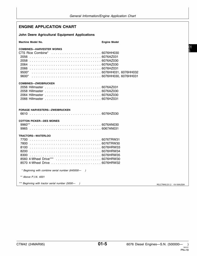
ENGINE APPLICATION CHART
John Deere Agricultural Equipment Applications
Machine Model No. Engine Model
COMBINES—HARVESTER WORKS
CTS Rice Combine* . . . . . . . . . . . . . . . . . . . . . . . 6076HH030 2056 . . . . . . . . . . . . . . . . . . . . . . . . . . . . . . . . . 6076AZ031 2058 . . . . . . . . . . . . . . . . . . . . . . . . . . . . . . . . . 6076AZ030 2064 . . . . . . . . . . . . . . . . . . . . . . . . . . . . . . . . . 6076AZ030 2066 . . . . . . . . . . . . . . . . . . . . . . . . . . . . . . . . . 6076HZ031 9500* . . . . . . . . . . . . . . . . . . . . . . . . . . . . . . . . 6076HH031, 6076HH032 9600* . . . . . . . . . . . . . . . . . . . . . . . . . . . . . . . . 6076HH030, 6076HH031
COMBINES—ZWEIBRUCKEN
2056 Hillmaster . . . . . . . . . . . . . . . . . . . . . . . . . . 6076AZ031 2058 Hillmaster . . . . . . . . . . . . . . . . . . . . . . . . . . 6076AZ030 2064 Hillmaster . . . . . . . . . . . . . . . . . . . . . . . . . . 6076AZ030 2066 Hillmaster . . . . . . . . . . . . . . . . . . . . . . . . . . 6076HZ031
FORAGE HARVESTERS—ZWEIBRUCKEN
6610 . . . . . . . . . . . . . . . . . . . . . . . . . . . . . . . . . 6076HZ030
COTTON PICKER—DES MOINES
9960** . . . . . . . . . . . . . . . . . . . . . . . . . . . . . . . . 6076AN030 9965 . . . . . . . . . . . . . . . . . . . . . . . . . . . . . . . . . 6067AN031
TRACTORS—WATERLOO
7700 . . . . . . . . . . . . . . . . . . . . . . . . . . . . . . . . . 6076TRW31 7800 . . . . . . . . . . . . . . . . . . . . . . . . . . . . . . . . . 6076TRW30 8100 . . . . . . . . . . . . . . . . . . . . . . . . . . . . . . . . . 6076HRW33 8200 . . . . . . . . . . . . . . . . . . . . . . . . . . . . . . . . . 6076HRW34 8300 . . . . . . . . . . . . . . . . . . . . . . . . . . . . . . . . . 6076HRW35 8560 4-Wheel Drive*** . . . . . . . . . . . . . . . . . . . . . 6076HRW30 8570 4-Wheel Drive . . . . . . . . . . . . . . . . . . . . . . . 6076HRW32
* Beginning with combine serial number (645000— )
** Above P.I.N. 4001
*** Beginning with tractor serial number (5000— ) RG,CTM42,G1,3 -19-16AUG94
General Information/Engine Application Chart
CTM42 (24MAR95) 01-5 6076 Diesel Engines—S.N. (500000— )160101
PN=18
015

ENGINE APPLICATION CHART—CONTINUED
John Deere Industrial Equipment Applications
Machine Model No. Engine Model
LOADERS—DUBUQUE
644G . . . . . . . . . . . . . . . . . . . . . . . . . . . . . . . . . 6076ADW30 644GH . . . . . . . . . . . . . . . . . . . . . . . . . . . . . . . . 6076ADW32 644G Dual Power . . . . . . . . . . . . . . . . . . . . . . . . 6076ADW33
MOTOR GRADERS—DUBUQUE
770B . . . . . . . . . . . . . . . . . . . . . . . . . . . . . . . . . 6076TDW30 770BH . . . . . . . . . . . . . . . . . . . . . . . . . . . . . . . . 6076ADW31 772BH . . . . . . . . . . . . . . . . . . . . . . . . . . . . . . . . 6076ADW31
EXCAVATORS—DUBUQUE
892E . . . . . . . . . . . . . . . . . . . . . . . . . . . . . . . . . 6076AT030
BULLDOZERS—DUBUQUE
850C . . . . . . . . . . . . . . . . . . . . . . . . . . . . . . . . . 6076AT032
OEM APPLICATIONS
Machine Model No. Engine Model
Marine . . . . . . . . . . . . . . . . . . . . . . . . . . . . . . . 6076AFM030
OEM Repower . . . . . . . . . . . . . . . . . . . . . . . . . . 6076AF0306076HF0306076TF030
RG,CTM42,G1,3B -19-16AUG94
RG,CTM42,G1,3A -19-16AUG94
General Information/Engine Application Chart
CTM42 (24MAR95) 01-6 6076 Diesel Engines—S.N. (500000— )160101
PN=19
016

DIESEL FUEL
Consult your local fuel distributor for properties of thediesel fuel available in your area.
In general, diesel fuels are blended to satisfy the lowtemperature requirements of the geographical area inwhich they are marketed.
Diesel fuels specified to EN 590 or ASTM D975 arerecommended.
In all cases, the fuel must meet the followingproperties:
• Cetane Number 40 minimum. Cetane numbergreater than 50 is preferred, especially fortemperatures below -20˚ C (-4˚ F) or elevationsabove 1500 m (5000 ft).
• Cold Filter Plugging Point (CFPP) below theexpected low temperature OR Cloud Point at least5˚ C (9˚ F) below the expected low temperature.
• Sulfur Content— Sulfur content should not exceed 0.5%. Sulfurcontent less than 0.05% is preferred.— If diesel fuel with sulfur content greater than 0.5%is used, reduce the service interval for engine oil andfilter changes by 50%.— DO NOT use diesel fuel with sulfur content greaterthan 1.0%.
Bio-diesel fuels meeting DIN 51606 or equivalentspecification may be used.
LUBRICITY OF DIESEL FUELS
Diesel fuel must have adequate lubricity to ensureproper operation and durability of fuel injection systemcomponents.
Diesel fuels for highway use in the United States nowrequire sulfur content less than 0.05%. Diesel fuel inthe European Union will require sulfur content lessthan 0.05% by 1 October 1996.
Experience shows that some low sulfur diesel fuelsmay have inadequate lubricity and their use mayreduce performance in fuel injection systems due toinadequate lubrication of injector components. Thelower concentration of aromatic compounds in thesefuels also adversely affects injection pump seals andmay result in leaks.
Use of low lubricity diesel fuels may also causeaccelerated wear, injection nozzle erosion orcorrosion, engine speed instability, hard starting, lowpower, and engine smoke.
Fuel lubricity should pass a minimum of 3300 gramload level as measured by the BOCLE scuffing test.
ASTM D975 and EN 590 specifications do not requirefuels to pass a fuel lubricity test. Diesel fuels meetingU.S. Military Specification VV—F—800E pass a fuellubricity test.
If fuel of low or unknown lubricity is used, add JohnDeere ALL-SEASON DIESEL FUEL CONDITIONERor equivalent at the specified concentration.
RG,FUEL1 -19-22FEB95
RG,FUEL5 -19-22FEB95
Group 02Fuels, Lubricants, and Coolant
CTM42 (24MAR95) 02-1 6076 Diesel Engines—S.N. (500000— )160101
PN=20
021

ENGINE BREAK-IN OIL
New engines are filled at the factory with John DeereENGINE BREAK-IN OIL. During the break-in period,add John Deere ENGINE BREAK-IN OIL as neededto maintain the specified oil level.
Change the oil and filter after the first 100 hours ofoperation of a new or rebuilt engine.
After engine overhaul, fill the engine with John DeereENGINE BREAK-IN OIL.
If John Deere ENGINE BREAK-IN OIL is notavailable, use a diesel engine oil meeting one of thefollowing during the first 100 hours of operation:
• API Service Classification CE• CCMC Specification D4
After the break-in period, use John Deere PLUS-50®
or other diesel engine oil as recommended in thismanual.
IMPORTANT: Do not use John Deere PLUS-50 oilor engine oils meeting API CG4,API CF4, or CCMC D5 performancelevels during the first 100 hours ofoperation of a new or rebuilt engine.These oils will not allow the engineto break-in properly.
DX,ENOIL4 -19-17OCT94
Fuels, Lubricants, and Coolant/Engine Break-In Oil
CTM42 (24MAR95) 02-2 6076 Diesel Engines—S.N. (500000— )160101
PN=21
022

DIESEL ENGINE OIL
Use oil viscosity based on the expected air temperaturerange during the period between oil changes.
The following oil is preferred.
• John Deere PLUS-50®
If John Deere PLUS-50 engine oil and a John Deere oilfilter are used, the service interval for oil and filterchanges may be extended by 50 hours.
The following oil is also recommended:
• John Deere TORQ-GARD SUPREME®
Other oils may be used if they meet one or more of thefollowing:
• John Deere UNI-GARD™• API Service Classification CG-4• API Service Classification CF-4• API Service Classification CE• CCMC Specification D5 and Mercedes Benz MB228.3• CCMC Specification D4 and Mercedes Benz MB228.1
Viscosity grade SAE 15W-40 is preferred.
If diesel fuel with sulfur content greater than 0.5% isused, reduce the service interval by 50%.
TS
1619
-U
N-1
2SE
P94
DX,ENOIL -19-16SEP94
Fuels, Lubricants, and Coolant/Engine Oil
CTM42 (24MAR95) 02-3 6076 Diesel Engines—S.N. (500000— )160101
PN=22
023

OILSCAN® AND COOLSCAN™
OILSCAN and COOLSCAN are John Deere samplingprograms to help you monitor machine performance andidentify potential problems before they cause seriousdamage.
Oil and coolant samples should be taken from eachsystem prior to its recommended change interval.
Check with your John Deere dealer for the availability ofOILSCAN and COOLSCAN kits. T
6828
AB
-UN
-15J
UN
89T
6829
AB
-UN
-18O
CT
88
GREASE
Use grease based on the expected air temperaturerange during the service interval.
The following greases are preferred:
• John Deere MOLY HIGH TEMPERATURE EPGREASE• John Deere HIGH TEMPERATURE EP GREASE• John Deere GREASE-GARD™
Other greases may be used if they meet one of thefollowing:
• SAE Multipurpose EP Grease with a maximum of 5% molybdenum disulfide• SAE Multipurpose EP Grease
Greases meeting Military Specification MIL-G-10924Fmay be used as arctic grease.
TS
1622
-U
N-0
2NO
V94
DX,OILSCAN -19-16APR92
DX,GREA1 -19-02NOV94
Fuels, Lubricants, and Coolant/Grease
CTM42 (24MAR95) 02-4 6076 Diesel Engines—S.N. (500000— )160101
PN=23
024

ALTERNATIVE AND SYNTHETIC LUBRICANTS
Conditions in certain geographical areas may requirelubricant recommendations different from thoseprinted in this manual. Some John Deere lubricantsmay not be available in your location. Consult yourJohn Deere dealer to obtain information andrecommendations.
Synthetic lubricants may be used if they meet theperformance requirements listed in this manual.
ENGINE COOLANT REQUIREMENTS
A—Quality Water B—Ethylene Glycol Concentrate C—Supplemental Coolant Additives(Antifreeze) (SCA’s)
Engine Coolant
To meet cooling system protection requirements, thecoolant MUST consist of a 50/50 mixture of qualitywater and ethylene glycol concentrate (antifreeze).Supplemental coolant additives (SCA’s) must beadded to this mixture. Add 3% (by volume) TY16004or TY16005 Liquid Coolant Conditioner. If anequivalent product is used, always follow thesupplier’s recommendations printed on the container.See ENGINE COOLANT SPECIFICATIONS, later inthis section, for further definition.
Makeup of the coolant between changes MUSTconsist of the same requirements as during acomplete change. Performing a CoolScan analysis isthe recommended method for determining the amountof quality water, ethylene glycol concentrate, andsupplemental coolant additives that should be added.
IMPORTANT: Supplemental coolant additivesMUST be added to the coolantsolution. Ethylene glycol concentrate(antifreeze) DOES NOT containchemical inhibitors needed tocontrol liner pitting or erosion, rust,scale, and acidity.
RG
6258
-U
N-2
2AP
R92
DX,ALTER -19-01FEB94
RG,COOL1 -19-10OCT94
Fuels, Lubricants, and Coolant/Engine Coolant Requirements
CTM42 (24MAR95) 02-5 6076 Diesel Engines—S.N. (500000— )160101
PN=24
025

ENGINE COOLANT REQUIREMENTS—CONTINUED
A—Cylinder Liner Walls B—Engine Coolant C—Vapor Bubbles
Coolant solutions of ethylene glycol concentrate(antifreeze), quality water, and supplemental coolantadditives (SCA’s) MUST be used year-round toprotect against freezing, boil-over, liner erosion orpitting, and to provide a stable, non-corrosiveenvironment for seals, hoses, and metal engine parts.
Water pump impellers and cylinder liner walls (A)which are in contact with engine coolant (B) can beeroded or pitted unless the proper concentration andtype of SCA’s are present in the coolant solution.
Vapor bubbles (C) are formed when piston impactsagainst liner ID causing walls to vibrate; sendingcompression waves into the coolant.
Erosion or pitting is caused by the formation andcollapse of tiny vapor bubbles in the coolant on thesurface of metal parts. Over a period of time, thispitting will progress completely through the metal.Generally, the most critical erosion occurs in thecylinder liner area of wet-sleeve, heavy-duty engines.If coolant is allowed to enter the combustionchamber, engine failure or other serious damage willresult.
Use of SCA’s will reduce the effects of erosion andpitting. The chemicals in the additives form aprotective film on cylinder liner surface. This film actsas a barrier against collapsing vapor bubbles andalso reduces the quantity of bubbles formed.
RG
6263
-U
N-2
2AP
R92
RG,COOL1A -19-10OCT94
Fuels, Lubricants, and Coolant/Engine Coolant Requirements
CTM42 (24MAR95) 02-6 6076 Diesel Engines—S.N. (500000— )160101
PN=25
026

RECOMMENDED ENGINE COOLANT
Solutions of antifreeze and supplemental coolantadditives MUST be used year-round for freezeprotection, boil-over protection, and to provide astable, non-corrosive environment for seals, hosesand metal engine parts.
John Deere Prediluted Antifreeze/Summer Coolant ispreferred. John Deere Antifreeze/Summer CoolantConcentrate and John Deere COOL-GARD™, whereavailable, are also recommended.
Refer to your vehicle operator’s manual for theservice life of these products.
• JOHN DEERE PREDILUTEDANTIFREEZE/SUMMER COOLANT
This product contains all the necessary ingredientsthat make up the proper coolant solution: chemicallypure water, ethylene glycol (low silicate antifreeze),and supplemental coolant additives (SCA’s). It isready to use; no mixing is required.
John Deere Prediluted Antifreeze/Summer Coolantpermits extended service life.
• JOHN DEERE ANTIFREEZE/SUMMER COOLANTCONCENTRATE
This product contains ethylene glycol (low silicateantifreeze) and supplemental coolant additives(SCA’s). It must be mixed with quality water, asdescribed later in this section, before adding to theengine cooling system. The proportion of water to beused depends upon the lowest freeze protectiontemperature desired according to the following table:
% CONCENTRATE FREEZE PROTECTION LIMIT40 -24˚ C (-12˚ F)50 -37˚ C (-34˚ F)60 -52˚ C (-62˚ F)
• JOHN DEERE COOL-GARD™
In certain geographical areas, John DeereCOOL-GARD is marketed for use in the enginecooling system. This product contains all thenecessary ingredients that make up the propercoolant solution: chemically pure water, ethyleneglycol (low silicate antifreeze), and supplementalcoolant additives (SCA’s). It is ready to add to coolingsystem as is; no mixing or supplemental coolantadditives required. Contact your John Deere PartsNetwork for local availability.
RG,COOL2,CTM -19-23FEB95
Fuels, Lubricants, and Coolant/Recommended Engine Coolant
CTM42 (24MAR95) 02-7 6076 Diesel Engines—S.N. (500000— )160101
PN=26
027

ENGINE COOLANT SPECIFICATIONS
Contact your authorized servicing dealer or enginedistributor to determine what the cooling system ofthis engine is filled with and the winter freezeprotection level.
If John Deere coolant products are not used, otherlow silicate ethylene glycol base coolants forheavy-duty diesel engines may be used when mixedwith quality water and supplemental coolant additives(SCA’s), if they meet one of the followingspecifications:
• ASTM D5345 (prediluted coolant)• ASTM D4985 (coolant concentrate) in a 40 to 60%mixture of concentrate with quality water.
Coolants meeting these specifications require additionof supplemental coolant additives (SCA’s), formulatedfor heavy-duty diesel engines, for protection againstcorrosion and cylinder liner erosion and pitting.
Water Quality:
Distilled, de-ionized, or demineralized water ispreferred for use in cooling systems. Mineral(hard/tap) water should NEVER be put in a coolingsystem unless first tested. However, water that meetsthe following water quality specifications isacceptable.
Water Quality Specifications
Parts GrainsPer Per
Item Million GallonChlorides (maximum) . . . . . . . . . . . . . . . . . 40 2.5Sulfates (maximum) . . . . . . . . . . . . . . . . . . 100 5.9Total Dissolved Solids (maximum) . . . . . . . . . 340 20Total Hardness (maximum) . . . . . . . . . . . . . 170 10
pH Level . . . . . . . . . . . . . . . . . . . . . . . . . . . . . . . . . 5.5—9.0
If Chlorides, Sulfates, or Total Dissolved Solids arehigher than the above given specifications, the watermust be distilled, de-mineralized, or de-ionized beforeusing in cooling system.
If Total Hardness is higher than the above givenspecification and all other parameters are within thegiven specifications, the water must be softenedbefore using in cooling system.
Ethylene Glycol Concentrate (Antifreeze):
IMPORTANT: DO NOT use ethylene glycolconcentrate containing sealer orstop-leak additives.
RG,COOL3 -19-23FEB95
Fuels, Lubricants, and Coolant/Engine Coolant Specifications
CTM42 (24MAR95) 02-8 6076 Diesel Engines—S.N. (500000— )160101
PN=27
028

ENGINE COOLANT SPECIFICATIONS—CONTINUED
Supplemental Coolant Additives (SCA’s):
IMPORTANT: DO NOT over-inhibit antifreezesolutions, as this can causesilicate-dropout. When this happens,a gel-type deposit is created whichretards heat transfer and coolantflow.
NOTE: John Deere Prediluted Antifreeze/SummerCoolant, John Deere Antifreeze/SummerCoolant Concentrate, and John DeereCOOL-GARD contain supplemental coolantadditives (SCA’s). However, as the coolantsolution loses its effectiveness, additives willneed to be added.
Inhibit the antifreeze-coolant mix with a non-chromateinhibitor such as John Deere Liquid CoolantConditioner. SCA’s guard against rust, corrosion, andliner pitting. ALWAYS follow the supplier’srecommendations printed on the container.
John Deere Liquid Coolant Conditioner is available inthe following sizes:
—TY16004 473 mL (16 oz) container—TY16005 3.8 L (1 US gal) container
IMPORTANT: Check inhibitors between drainintervals. Replenish inhibitors by theaddition of a supplemental coolantadditive as necessary. See yourvehicle operator’s manual fordetails.
DO NOT use soluble oil.
Additives eventually lose their effectiveness and mustbe recharged with additional liquid coolant conditioner.See label on container for recommended serviceintervals and concentration rates. SeeREPLENISHING SUPPLEMENTAL COOLANTADDITIVES (SCA’S) BETWEEN COOLANTCHANGES, later in this group.
Contact your authorized servicing dealer or enginedistributor, if there are further questions.
RG
7298
-U
N-1
3FE
B95
RG,COOL3A,CTM -19-23FEB95
Fuels, Lubricants, and Coolant/Engine Coolant Specifications
CTM42 (24MAR95) 02-9 6076 Diesel Engines—S.N. (500000— )160101
PN=28
029

REPLENISHING SUPPLEMENTAL COOLANT ADDITIVES (SCA’S) BETWEEN COOLANTCHANGES
Through time and use, original additives eventuallylose their effectiveness and must be recharged withadditional supplemental coolant additives available inthe form of liquid coolant conditioner.
Maintaining the correct coolant conditionerconcentration (SCA’s) and freeze point is essential inyour cooling system to protect against liner pitting,corrosion, and freeze-ups due to incorrect coolantsolution.
A coolant strip test, available from your dealer,provides a simple, effective way to check freeze pointand molybdate/nitrite levels. These results can becompared to the SCA chart to determine the amountof coolant conditioner in your system.
NOTE: Refer to your vehicle operator’s manual forspecific service intervals for checking andcharging your coolant.
For a more thorough evaluation of your coolant,perform a CoolScan analysis. If a CoolScan analysisis not available, recharge system per instructionsprinted on label of TY16004 or TY16005 John DeereLiquid Coolant Conditioner.
IMPORTANT: ALWAYS maintain coolant at correctlevel and concentration. DO NOToperate engine without coolant foreven a few minutes.
If frequent coolant make-up isrequired, the glycol concentrationshould be checked with JT05460Refractometer to assure that thedesired freeze point is maintained.Follow manufacturer’s instructionsprovided with refractometer.
See ENGINE COOLANT SPECIFICATIONS earlier inthis group for proper mixing of coolant ingredientsbefore adding to the cooling system.
RG
6261
-U
N-2
2AP
R92
RG
6262
-U
N-2
2AP
R92
RG,COOL4,CTM -19-23FEB95
Fuels, Lubricants, and Coolant/Replenish Supplemental Coolant Additives Between Coolant Changes
CTM42 (24MAR95) 02-10 6076 Diesel Engines—S.N. (500000— )160101
PN=29
0210

OPERATING IN TROPICAL CONDITIONS
Always use a recommended glycol base enginecoolant, even when operating in geographical areaswhere freeze protection is not required.
Only when no glycol base engine coolant (antifreeze)is available, use distilled, deionized, or demineralizedwater meeting the quality specifications on theprevious page. Add to the water an initial charge ofsupplemental coolant additives, such as John DeereLiquid Coolant Conditioner or equivalent. Therecommended concentration of John Deere LiquidCoolant Conditioner must be doubled to 6% (60 mLper Liter of cooling system capacity) by volume whenused with water only (no antifreeze). Double othermanufacturer’s recommended concentration.
IMPORTANT: Never use water as the enginecoolant without an initial charge ofsupplemental coolant additives.Using water alone will cause severecorrosion and pitting damage tovital engine parts. Drain system andrefill cooling system as specified inyour vehicle operator’s manual.
RG,COOL6,CTM -19-23FEB95
Fuels, Lubricants, and Coolant/Operating in Tropical Conditions
CTM42 (24MAR95) 02-11 6076 Diesel Engines—S.N. (500000— )160101
PN=30
0211

FLUSH AND SERVICE COOLING SYSTEM
N CAUTION: Explosive release of fluids frompressurized cooling system can causeserious burns.
Shut off engine. Only remove filler capwhen cool enough to touch with barehands. Slowly loosen cap to first stop torelieve pressure before removing capcompletely.
IMPORTANT: Air must be expelled from coolingsystem when system is refilled.Follow procedure given in youroperator’s manual.
The ethylene glycol base (antifreeze) can becomedepleted of SCA’s allowing various acids to form thatwill damage engine components. In addition, heavymetals, such as lead, copper and zinc, accumulate inthe ethylene glycol base. The heavy metals comefrom corrosion that occurs to some degree within acooling system. When a coolant is saturated to thepoint where it can no longer hold heavy metals andother dissolved solids, they settle out and act asabrasives on engine parts.
NOTE: Refer to your operator’s manual for a specificservice interval.
Flush cooling system and replace thermostats asdescribed in your operator’s manual. Clean coolingsystem with clean water and TY15979 John DeereHeavy-Duty Cooling System Cleaner or an equivalentcleaner such as FLEETGUARD® RESTORE™. Followthe instructions provided with the cleaner. Refillcooling system with the appropriate coolant solution.See ENGINE COOLANT SPECIFICATIONS, earlier inthis group.
IMPORTANT: NEVER overfill the system. Apressurized system needs space forheat expansion without overflowingat the top of the radiator. Coolantlevel should be at bottom of radiatorfiller neck.
After adding new coolant solution, run engine until itreaches operating temperature. This mixes thecoolant solution uniformly and circulates it through theentire system. After running engine, check coolantlevel and entire cooling system for leaks.
Contact your authorized servicing dealer or enginedistributor, if there are further questions.
FLEETGUARD® is a registered trademark of Cummins EngineCompany.
RESTORE™ is a trademark of FLEETGUARD®.
TS
281
-U
N-2
3AU
G88
RG,COOL,REQ8B -19-17AUG94
Fuels, Lubricants, and Coolant/Flush and Service Cooling System
CTM42 (24MAR95) 02-12 6076 Diesel Engines—S.N. (500000— )160101
PN=31
0212

DISPOSING OF COOLANT
Improperly disposing of engine coolant can threaten theenvironment and ecology.
Use leakproof containers when draining fluids. Do notuse food or beverage containers that may misleadsomeone into drinking from them.
Do not pour waste onto the ground, down a drain, orinto any water source.
Inquire on the proper way to recycle or dispose of wastefrom your local environmental or recycling center, or fromyour John Deere dealer.
TS
1133
-U
N-2
6NO
V90
RG,COOL5 -19-01SEP94
Fuels, Lubricants, and Coolant/Disposing of Coolant
CTM42 (24MAR95) 02-13 6076 Diesel Engines—S.N. (500000— )160101
PN=32
0213

Fuels, Lubricants, and Coolant/Disposing of Coolant
CTM42 (24MAR95) 02-14 6076 Diesel Engines—S.N. (500000— )160101
PN=33
0214

ENGINE REPAIR STAND
NOTE: Only the 2722 kg (6000 lb) heavy duty enginerepair stand (A) No. D05223ST manufactured byOwatonna Tool Co., Owatonna, Minnesota isreferenced in this manual. When any other repairstand is used, consult the manufacturer’sinstructions for mounting the engine.
RG
4929
-U
N-1
5DE
C88
S11,2000,EM -19-08MAR94
Group 03Engine Mounting
CTM42 (24MAR95) 03-1 6076 Diesel Engines—S.N. (500000— )160101
PN=34
031

SAFETY PRECAUTIONS
• The engine repair stand should be used only byqualified service technicians familiar with thisequipment.
• To maintain shear strength specifications, alloy steelSAE Grade 8 or higher cap screws must be used tomount adapters and engine to repair stand. UseLOCTITE® 242 Thread Lock and Sealer on capscrews when installing lifting straps on engine.Tighten cap screws to 170 N·m (125 lb-ft).
• For full thread engagement, be certain that tappedholes in adapters and engine blocks are clean andnot damaged. A thread length engagement equal to1-1/2 screw diameters minimum is required tomaintain strength requirements.
• To avoid structural or personal injury, do not exceedthe maximum capacity rating of 2722 kg (6000 lb).Maximum capacity is determined with the center ofthe engine located not more than 330 mm (13 in.)from the mounting hub surface of the engine stand.
• To avoid an unsafe off-balance load condition, thecenter of balance of an engine must be located within51 mm (2 in.) of the engine stand rotating shaft.Engine center of balance is generally located a fewmillimeters above the crankshaft.
• To prevent possible personal injury due to engineslippage, recheck to make sure engine is solidlymounted before releasing support from engine liftingdevice.
• Never permit any part of the body to be positionedunder a load being lifted or suspended. Accidentalslippage may result in personal injury.
• The lifting jack is to be used when it is necessary tolift the engine for rotation. When working on theengine, the jack should be at its lowest position tokeep the center of gravity low and the possibility oftipping low.
• To prevent possible personal injury due to suddenengine movement, lower engine by operating jackrelease valve slowly. Do not unscrew release valveknob more than two turns from its closed position.
LOCTITE® is a registered trademark of Loctite Corporation.
INSTALL 400 SERIES ADAPTERS ONREPAIR STAND
1. Attach the No. 60581 Engine Adapter (A) to mountinghub of the engine repair stand using SAE Grade 8socket head screws. Tighten screws to 135 N·m (100lb-ft).
2. Attach the No. 51400 end adapter (B) to the engineadapter, using four 5/8-11 x 2 in. SAE Grade 8 capscrews. Tighten screws to 135 N·m (100 lb-ft).
RG
4930
-U
N-1
5DE
C88
S11,2000,DZ -19-21MAR95
S11,2000,FB -19-08MAR94
Engine Mounting/Install 400 Series Adapters on Repair Stand
CTM42 (24MAR95) 03-2 6076 Diesel Engines—S.N. (500000— )160101
PN=35
032

ENGINE LIFTING PROCEDURE
N CAUTION: Use of JDG23 Engine LiftingSling (A) is the ONLY APPROVED methodfor lifting engine. Use extreme caution whenlifting and NEVER permit any part of thebody to be positioned under an enginebeing lifted or suspended.
1. Attach the JDG23 Engine Lifting Sling to enginelifting straps (B) and overhead hoist or floor crane.
IMPORTANT: Ensure that engine lifting straps aresecured to engine with SAE Grade 8(or higher) cap screws. ApplyLOCTITE 242 Thread Lock andSealer and tighten cap screws to170 N·m (125 lb-ft).
NOTE: If engine does not have lifting straps, they canbe procured through service parts network.USE ONLY lifting straps supplied by DEERE.
2. Carefully lift engine and slowly lower to desiredlocation.
RG
5788
-U
N-0
9AU
G91
RG,CTM42,G3,1 -19-23MAR95
Engine Mounting/Engine Lifting Procedure
CTM42 (24MAR95) 03-3 6076 Diesel Engines—S.N. (500000— )160101
PN=36
033

CLEAN ENGINE
1. Cap or plug all openings on engine. If electricalcomponents (starter, alternator, etc.) are not removedprior to cleaning, cover with plastic and tape securely toprevent moisture from entering.
2. Steam-clean engine thoroughly.
IMPORTANT: Never steam clean or pour cold wateron an injection pump while it is stillwarm. To do so may cause seizure ofpump parts.
DISCONNECT TURBOCHARGER OIL INLETLINE
1. Drain all engine oil and coolant, if not previously done.
IMPORTANT: When servicing 6076 Engines on arollover stand, disconnect turbochargeroil inlet line (A) from oil conditioninghousing or turbocharger before rollingengine over. Failure to do so maycause a hydraulic lock upon startingengine. Hydraulic lock may causepossible engine failure.
Hydraulic lock occurs when trapped oilin the oil filter housing drains throughthe turbocharger, the exhaust andintake manifolds, and then into thecylinder head.
After starting the engine, the trappedoil in the manifold and head is releasedinto the cylinder(s) filling them with oilcausing hydraulic lock and possibleengine failure.
2. Disconnect turbocharger oil inlet line at turbochargeror oil conditioning housing.
RG
5323
-U
N-0
6DE
C88
S11,2000,EC -19-20AUG92
RG,CTM42,G03,3 -19-24SEP91
Engine Mounting/Disconnect Turbocharger Oil Inlet Line
CTM42 (24MAR95) 03-4 6076 Diesel Engines—S.N. (500000— )160101
PN=37
034

MOUNT ENGINE ON REPAIR STAND
NOTE: If starting motor is to be removed fromengine, remove before mounting engine ontorepair stand.
N CAUTION: Never remove the overheadlifting equipment from the equipment untilthe engine is securely mounted to the standand all mounting hardware is tightened tospecified values. Always release theoverhead lifting equipment slowly.
1. Mount the starter side of the engine to the engineadapter with four 5/8-11UNC Flanged-head, SAEGrade 8 or higher grade cap screws (A).
2. Tighten cap screws to 203 N·m (150 lb-ft).
3. Carefully remove lift sling from engine.
RG
5965
-U
N-0
5SE
P91
RG,CTM42,G3,2 -19-21MAR95
Engine Mounting/Mount Engine On Repair Stand
CTM42 (24MAR95) 03-5 6076 Diesel Engines—S.N. (500000— )160101
PN=38
035

Engine Mounting/Mount Engine On Repair Stand
CTM42 (24MAR95) 03-6 6076 Diesel Engines—S.N. (500000— )160101
PN=39
036

6076 ENGINE DISASSEMBLY SEQUENCE
The following sequence is suggested when completedisassembly for overhaul is required. Refer to theappropriate repair group when removing individualengine components.
NOTE: Remove starting motor before mountingengine into repair stand.
1. Drain all coolant and engine oil. Check engine oilfor metal contaminates.
2. Remove turbocharger oil inlet line.
3. Remove breather hose.
4. Remove fan pulley and water manifold assembly.
5. Remove turbocharger exhaust elbow andconnector. Remove turbocharger.
NOTE: DO NOT damage option code label (ifequipped), when removing rocker arm cover.
6. Remove rocker arm cover.
7. Remove rocker arm assembly and push rods.Identify parts for re-assembly.
8. Remove alternator and mounting brackets.
9. Remove front crankshaft pulley and damperassembly.
10. Remove fuel injection lines and injection nozzles.
11. Remove water pump.
12. Remove engine oil filter and oil conditioninghousing.
13. Remove injection pump gear cover and removeinjection pump. Remove fuel filter and mounting base.
14. On 6076A Engines, remove aftercooler cover andaftercooler assembly.
15. Remove exhaust manifold and air intake manifold.
16. Remove turbocharger oil return line.
17. Remove cylinder head with valve assembly.Remove head gasket.
18. On SAE No. 3 flywheel housings, removeflywheel then remove flywheel housing.
19. On SAE No. 1 and 2 flywheel housings, removeflywheel housing and then remove flywheel.
20. Roll engine over and remove oil pan and engineoil pump assembly.
21. Remove front timing gear cover.
22. Rotate engine to vertical position. Remove pistonsand connecting rods. Identify for re-assembly. Performwear checks with PLASTIGAGE™.
NOTE: Perform wear check on main bearing surfaceswith PLASTIGAGE, when removing mainbearing caps.
23. Remove main bearing caps. Remove crankshaftand main bearings. Identify for re-assembly.
24. Remove camshaft and cam followers. Identify forre-assembly.
25. Rotate engine and remove liners and their O-ringseals. Mark liners for reassembly in same bore fromwhich removed.
26. Remove piston cooling orifices.
27. Remove cylinder block plugs and engine serialnumber plate, if block is to be put in a “hot tank”.
28. Refer to appropriate group for inspection andrepair of engine components.
PLASTIGAGE™ is a trademark of the Perfect Circle Division of DanaCorp. RG,CTM42,G4,1 -19-24SEP91
Group 04Engine Rebuild Guide
CTM42 (24MAR95) 04-1 6076 Diesel Engines—S.N. (500000— )160101
PN=40
041

SEALANT APPLICATION GUIDELINES
Listed below are sealants which have been testedand are used by the John Deere factory to controlleakage and assure hardware retention. ALWAYS usethe following recommended sealants whenassembling your John Deere Diesel Engine to assurequality performance.
LOCTITE® products are designed to perform tosealing standards with machine oil residue present. Ifexcessive machine oil or poor cleanliness qualityexist, clean with solvent. Refer to John DeereMerchandise and Parts Sales Manual for orderinginformation.
• LOCTITE 242 Thread Lock & Sealer (MediumStrength) (blue):
TY9370 6 ml. (0.2 oz) tube T43512 50 ml. (1.7oz) bottle
—Plugs and fittings: fuel filter base, intake manifold,cylinder block (oil galley).
—Cap Screws: injection pump access cover,tachometer drive, oil filler inlet, flywheel, water outletmanifold, engine lifting straps.
—Oil pressure sending unit
• LOCTITE 271 Thread Lock & Sealer (HighStrength) (clear):
TY9371 6 ml. (0.2 oz) tube T43513 50 ml. (1.7oz) bottle
—Studs: Injection pump-to-block and exhaustmanifold-to-turbocharger.
—Oil filter adapter.
—Steel cap plugs: cylinder block, cylinder head, andwater pump
• LOCTITE 515 Flexible Sealant:
TY6304 50 ml. (1.7 oz) bottle
—Water pump and water manifold gaskets
• LOCTITE 592 Pipe Sealant with TEFLON® (white):
TY9374 6 ml. (0.2 oz) tube TY9375 50 ml. (1.7 oz) bottle
—Pipe plugs: cylinder block (water manifold),thermostat housing, air intake manifold, tachometerdrive, water pump, fan drive, fuel filter drain andbleed.
—Drain valves: water pump and block
—Injection pump governor cover fitting (fuel return)
—Threaded nipples and elbows in water pumphousing
—Temperature sending unit
—Oil pan (drain hose and drain valve)
—Connectors: turbocharger oil supply and drain lines.
—Adapter fitting for turbocharger oil inlet line
• LOCTITE 609 Retaining Compound (green):
T43515 50 ml. (1.7 oz) bottle
—Crankshaft rear oil seal/wear sleeve, crankshaftfront wear sleeve
• PERMATEX® AVIATION (Form-A-Gasket No. 3):
TY6299 227 g (8 oz) container
—Timing gear cover-to oil pan
—Flywheel housing-to-oil pan
—Camshaft bore steel cap plug
RG,CTM42,G4,2 -19-17MAR95
Engine Rebuild Guide/Sealant Application Guidelines
CTM42 (24MAR95) 04-2 6076 Diesel Engines—S.N. (500000— )160101
PN=41
042

SEALANT APPLICATION GUIDELINES—CONTINUED
• PT569 NEVER-SEEZ® COMPOUND:
PT569 227 g (8 oz) Brush PT506 453 g (16 oz) Spray
—Cap Screws: exhaust manifold,turbocharger-to-exhaust manifold.
—Gland nut threads and fuel injection nozzle barrel.
• AR31790 SCOTCH-GRIP® EC-1099 PlasticAdhesive:
AR31790 118 ml (4 oz)
—Rocker arm cover gasket
• FEL-PRO® C-670 Molybdenum Disulfide Paste
—Camshaft nose (gear installation)
LOCTITE® and PERMATEX® are registered trademarks of LoctiteCorporation.
NEVER-SEEZ® is a registered trademark of the Emhart ChemicalGroup.
TEFLON® is a registered trademark of DuPont Co.
SCOTCH-GRIP® is a registered trademark of 3M Company.
FEL-PRO® is a registered trademark of FEL-PRO. RG,CTM42,G4,5 -19-16AUG94
Engine Rebuild Guide/Sealant Application Guidelines
CTM42 (24MAR95) 04-3 6076 Diesel Engines—S.N. (500000— )160101
PN=42
043

6076 ENGINE ASSEMBLY SEQUENCE
The following assembly sequence is suggested whenengine has been completely disassembled. Be sure tocheck run-out specifications, clearance tolerances,torques, etc., as engine is assembled. Refer to theappropriate repair group when assembling enginecomponents.
1. Install all plugs in cylinder block that were removedto service block. Install engine serial number plate.
2. Install clean piston cooling orifices.
3. Install cylinder liners without O-rings and measureliner stand-out. Install liner O-rings in block andpackings on liners. Install liners.
NOTE: If new piston and liner kit assemblies arebeing installed, install the crankshaft first.
4. Install main bearings and crankshaft. Rotatecrankshaft to assure correct assembly. Checkcrankshaft end play.
5. If installing new piston/liner kits, assemble therespective connecting rods.
6. Install engine oil pump assembly.
7. Install crankshaft rear oil seal housing, oil seal,and wear sleeve.
8. Install cam followers in hole from which originallyremoved.
9. Install camshaft. Align timing marks (camshaft tocrankshaft gears) with No. 1 piston at TDCcompression stroke.
10. Install fuel injection pump and drive gear.
11. Install engine oil conditioning assembly, ifremoved.
12. Install flywheels:
SAE 1 or SAE 2: Flywheel goes on before housing.
SAE 3: Housing goes on before flywheel.
13. Install cylinder head, push rods, and rocker armassembly. Measure valve lift and adjust valveclearance.
14. Install rocker arm cover. Install breather hose.
15. Install exhaust manifold and water manifold.
16. Install timing gear cover. Install front crankshaftwear sleeve and oil seal.
17. Install air intake manifold.
18. Install aftercooler assembly on 6076A Engines.
19. Install turbocharger with elbow and oil lines.
20. Install water pump.
21. Install injection nozzles and line assembly.
22. Install front pulley and damper as an assembly.
23. Install alternator. Install fan pulley assembly.
24. Install fuel filter base, supply lines, and filter.
25. Fill engine with clean oil and the proper coolant.Install dipstick.
26. Perform engine break-in and normal standardperformance checks.
RG,CTM42,G4,3 -19-14FEB95
Engine Rebuild Guide/6076 Engine Assembly Sequence
CTM42 (24MAR95) 04-4 6076 Diesel Engines—S.N. (500000— )160101
PN=43
044

SPECIAL OR ESSENTIAL TOOLS
NOTE: Order tools according to information given in theU.S. SERVICE-GARD™ Catalog or in theEuropean Microfiche Tool Catalog (MTC).
Spring Compression Tester . . . . . . . . . D01168AA
Test valve spring compression.
RG5061 -UN-23AUG88
Valve Inspection Center . . . . . . . . . . . . D05058ST
Check valves for out-of round.
RG5062 -UN-23AUG88
End Brush . . . . . . . . . . . . . . . . . . . . . D17024BR
Clean valve seat and bores.
RG5063 -UN-23AUG88
Nozzle Thread Cleaning Brush . . . . . . . . . D17030BR
Used to clean nozzle threads in cylinder head.
RG5099 -UN-23AUG88
Dial Indicator . . . . . . . . . . . . . (English, in.) D17526CIor (Metric, mm ) D17527CI
Use with JDG451 to measure valve recess and cylinderliner height-to-cylinder block top deck.
RG
6246
-U
N-2
7MA
R92
Valve Guide Knurler Kit . . . . . . . . . . . . . . . JT05949
Knurl valve guides.
RG5064 -UN-23AUG88
DX,TOOLS -19-05JUN91
S53,D01168,AA -19-13MAR92
S53,D05058,ST -19-02APR87
S53,D17024,BR -19-26JAN87
S53,D17030,BR -19-16FEB87
RG,D17526CI -19-29OCT92
S53,D20002,WI -19-16SEP92
Group 05Cylinder Head and Valves
CTM42 (24MAR95) 05-1 6076 Diesel Engines—S.N. (500000— )160101
PN=44
051

Valve Seat Pilot Driver . . . . . . . . . . . . . . . . JDE7
Install replacement valve seat inserts. Use with JDG605.
RG5065 -UN-23AUG88
Flywheel Turning Tool . . . . . . . . . . . . . . . . . JDG820
Used to rotate engine to check damper radial runout andtime engine. JDE81-1 may be used also if JDG820 isnot available.
RG
7056
-U
N-1
0AU
G94
Timing Pin . . . . . . . . . . . . . . . . . . . . . . . . . JDE81-4
Lock engine at TDC when timing valve train, adjustingvalve clearance, and installing fuel injection pump. Usewith JDG820 and JDE81-1 Flywheel Turning Tools.
RG5068 -UN-23AUG88
Valve Seat Puller . . . . . . . . . . . . . . . . . JDE41296
Remove valve seats.
RG5071 -UN-23AUG88
Tap . . . . . . . . . . . . . . . . . . . . . . . . . . . . . . . JDF5
Used to restore nozzle threads in cylinder head.
RG5100 -UN-23AUG88
Tap . . . . . . . . . . . . . . . . . . . . . . . . . . . . JDG681A
Used to restore threaded holes in cylinder block forcylinder head cap screws.
RG5100 -UN-23AUG88
S53,JDE7A -19-04FEB93
RG,JDG820 -19-14FEB95
RG,JDE814,86 -19-14FEB95
S53,JDE,41296 -19-26JAN87
S53,JDF5 -19-08MAR94
RG,JDG681A -19-17MAR95
Cylinder Head and Valves/Special or Essential Tools
CTM42 (24MAR95) 05-2 6076 Diesel Engines—S.N. (500000— )160101
PN=45
052

Valve Seat Installer . . . . . . . . . . . . . . . . JDG605
Install intake and exhaust valve seat inserts. Use withJDE7.
RG
5240
-U
N-2
3AU
G88
Nozzle Seat Reamer . . . . . . . . . . . . . . . . . . JDG609
Used to clean carbon from nozzle seats in cylinder head.
RG5289 -UN-23AUG88
SERVICE EQUIPMENT AND TOOLS
NOTE: Order tools from your SERVICE-GARD™Catalog. Some tools may be available from alocal supplier.
Name Use
JDE138 Valve Spring Compressor Compress valve springs when removing andinstalling valves
D05012ST Precision “Bevelled Edge” Straightedge Check cylinder head flatness
Plastic Brush Clean valve guides
D11010KW Eccentrimeter Measure valve seat-to-stem runout
JT05893 Heavy-Duty Seat Grinder Set Grind valve seats
S53,JDG605 -19-25MAR91
S53,JDG609 -19-02DEC87
S55,2505,AH -19-08FEB94
Cylinder Head and Valves/Service Equipment and Tools
CTM42 (24MAR95) 05-3 6076 Diesel Engines—S.N. (500000— )160101
PN=46
053

OTHER MATERIAL
Name Use
AR44402 Valve Stem Lubricant Lubricate valve stems.
PT569 NEVER-SEEZ Compound Exhaust manifold and cylinder head front platecap screws.
AR31790 SCOTCH-GRIP Plastic Adhesive Rocker arm cover gasket.
S11,2505,BW -19-30MAR93
Cylinder Head and Valves/Other Material
CTM42 (24MAR95) 05-4 6076 Diesel Engines—S.N. (500000— )160101
PN=47
054

CYLINDER HEAD AND VALVES SPECIFICATIONS
ITEM SPECIFICATION WEAR LIMIT
Valve Lift at 0.00 mm (in.) Clearance Intake . . . . . . . . . . . . . . . . . . . 13.53—13.71 mm (0.533—0.540 in.) 12.65 mm (0.498 in.) Exhaust . . . . . . . . . . . . . . . . . . 14.52—14.70 mm (0.572—0.579 in.) 13.64 mm (0.537 in.)
Valve Clearance With Engine Cold (Rocker Arm-to-Valve Tip): Intake . . . . . . . . . . . . . . . . . . . 0.331—0.431 mm (0.013—0.017 in.) —— Exhaust . . . . . . . . . . . . . . . . . . 0.457—0.559 mm (0.018—0.022 in.) ——
Valve Spring Compressed Height: Valve Closed-Intake . . . . . . . . . . 52.5 mm @ 345—399 N (2.07 in. @ 78—90 lb-force) —— Exhaust . . . . . . . . . . 54.5 mm @ 284—338 N (2.15 in. @ 64—76 lb-force) —— Valve Open-Intake . . . . . . . . . . . 38.1 mm @ 810—880 N (1.50 in. @ 182—198 lb-force) —— Exhaust . . . . . . . . . . 38.5 mm @ 797—867 N (1.52 in. @ 179—195 lb-force) ——
Valve Head OD: Intake . . . . . . . . . . . . . . . . . . . 50.87—51.13 mm (2.003—2.013 in.) —— Exhaust . . . . . . . . . . . . . . . . . . 46.87—47.13 mm (1.845—1.856 in.) ——
Valve Stem OD: Exhaust . . . . . . . . . . . . . . . . . . 9.44—9.46 mm (0.3717—0.3724 in.) —— Intake . . . . . . . . . . . . . . . . . . . 9.46—9.49 mm (0.3724—0.3736 in.) ——
Oversize Valve (Stem) Available . . . 0.08, 0.38, 0.76 mm (0.003, 0.015, 0.030 in.) ——
Valve Guide ID . . . . . . . . . . . . . . 9.51—9.54 mm (0.3745—0.3755 in.) ——
Valve Stem-to-Guide Clearance: Exhaust . . . . . . . . . . . . . . . . . . 0.051—0.102 mm (0.002—0.004 in.) —— Intake . . . . . . . . . . . . . . . . . . . 0.025—0.076 mm (0.001—0.003 in.) ——
Valve Face Angle . . . . . . . . . . . . . 29.25˚ ±0.25˚ ——
Valve Seat Angle . . . . . . . . . . . . . 30˚ ±0.50˚ ——
Valve Seat Width: Exhaust . . . . . . . . . . . . . . . . . . 2.0—3.8 mm (0.79—0.150 in.) —— Intake . . . . . . . . . . . . . . . . . . . 1.4—3.8 mm (0.055—0.150 in.) ——
Valve Seat Concentricity with Guide . . . . . . . . . . . . . . . . 0.051 mm (0.0020 in.) ——
Valve Recess in Cylinder Head: Intake . . . . . . . . . . . . . . . . . . . 3.35—3.86 mm (0.132—0.152 in.) 4.62 mm (0.182 in.) Exhaust . . . . . . . . . . . . . . . . . . 1.19—1.70 mm (0.047—0.067 in.) 2.46 mm (0.097 in.)
Maximum Valve Seat Runout . . . . . 0.051 mm (0.0020 in.) ——
Maximum Valve Face Runout . . . . . 0.051 mm (0.0020 in.) ——
RG,CTM42,G5,1 -19-14FEB95
Cylinder Head and Valves/Cylinder Head and Valves Specifications
CTM42 (24MAR95) 05-5 6076 Diesel Engines—S.N. (500000— )160101
PN=48
055

CYLINDER HEAD AND VALVES SPECIFICATIONS—CONTINUED
ITEM SPECIFICATION WEAR LIMIT
Cylinder Firing Order . . . . . . . . . . . . . . . . . 1-5-3-6-2-4 ——
Rocker Arm ID . . . . . . . . . . . . . . . . . . . . . 19.07—19.10 mm (0.7507—0.7520 in.) ——
Rocker Arm Shaft OD . . . . . . . . . . . . . . . . 19.01—19.05 mm (0.7484—0.7500 in.) ——
Cylinder Liner Height Above Block . . . . . . . . 0.050—0.127 mm (0.002—0.005 in.) ——
Cylinder Head Reconditioning: Thickness of Head (Rocker Arm Cover Gasket Rail-to- Combustion Face) . . . . . . . . . . . . . . . . 155.45—155.71 mm (6.120—6.130 in.) —— Minimum Acceptable Thickness . . . . . . . . 154.69 mm (6.09 in.) —— Maximum Acceptable Head Out-of-Flat (Entire Length or Width) . . . . . . . . . . . . 0.102 mm (0.0040 in.) —— Combustion Face Surface Finish (Surface Grind Only) . . . . . . . . . . 60—110AA —— Maximum Wave Depth . . . . . . . . . . . . . 0.008 mm (0.0003 in.) —— Maximum Material Removal for Resurfacing Head . . . . . . . . . . . . . . . . 0.762 mm (0.0300 in.) ——
CYLINDER HEAD AND VALVES SPECIFICATIONS—CONTINUED
TORQUES
Cylinder Head-to-Cylinder Block: Refer to TORQUE-TURN FLANGED-HEAD CAP SCREWS—GRADE 180 and TORQUE-TO-YIELD FLANGED-HEAD CAP SCREWS—GRADE 180 MARKED “SPECIAL”, later in this group.
Rocker Arm Shaft Clamps . . . . . . . . . . . . . . . . . . . . . . . . . . . . . . . . . . . . . . . . . . . . . . 75 N·m (55 lb-ft)
Rocker Arm Cover-to-Cylinder Head . . . . . . . . . . . . . . . . . . . . . . . . . . . . . . . . . . . 8 N·m (6 lb-ft) (72 lb-in.)
Intake Manifold-to-Cylinder Head . . . . . . . . . . . . . . . . . . . . . . . . . . . . . . . . . . . . . . . . . . 47 N·m (35 lb-ft)
Exhaust Manifold-to-Cylinder Head . . . . . . . . . . . . . . . . . . . . . . . . . . . . . . . . . . . . . . . . . 47 N·m (35 lb-ft)
Valve Adjusting Screw Locknut . . . . . . . . . . . . . . . . . . . . . . . . . . . . . . . . . . . . . . . . . . . 27 N·m (20 lb-ft)
RG,CTM42,G5,2 -19-14FEB95
RG,CTM42,G5,33A-19-14FEB95
Cylinder Head and Valves/Cylinder Head and Valves Specifications
CTM42 (24MAR95) 05-6 6076 Diesel Engines—S.N. (500000— )160101
PN=49
056

CHECK AND ADJUST VALVE CLEARANCE
Too little valve clearance throws valves out of time.Valves open too early and close too late. This causesthe valves to overheat due to hot combustion gasesrushing past valves when out of time. Overheatinglengthens valve stems which prevents proper seating ofvalves. The valves seat so briefly or poorly that normalheat transfer into the cooling system does not have timeto take place, causing burned valves and low power.
Too much valve clearance causes a lag in valve timingcausing engine valve train imbalance. The fuel-airmixture enters the cylinders late during intake stroke.The exhaust valve closes early and prevents wastegases from being completely removed from cylinders.Also, the valves close with a great deal of impact, whichmay crack or break the valves and scuff the camshaftand followers.
NOTE: Valve clearance should be checked with enginecold.
1. Remove rocker arm cover and ventilator hose (A).
2. Remove plastic plugs (B).
IMPORTANT: Visually inspect contact surfaces ofvalve tips or wear caps and rocker armwear pads. Check all parts forexcessive wear, breakage, or cracks.Replace parts that show visibledamage.
RG
5790
-U
N-0
9AU
G91
3. Rotate engine with the JDE81-1 or JDG820 FlywheelTurning Tool (A) until JDE81-4 Timing Pin (B) engagestiming hole in flywheel.
If the rocker arms for No. 1 cylinder are loose, theengine is at No. 1 “TDC-Compression.” If the rockerarms for No. 6 cylinder are loose, the engine is at No. 6“TDC-Compression.” Rotate the engine one full revolutionto No. 1 “TDC-Compression.”
RG
5791
-U
N-0
9AU
G91
RG,CTM42,G5,5 -19-03MAY93
RG,CTM42,G5,26 -19-14FEB95
Cylinder Head and Valves/Check and Adjust Valve Clearance
CTM42 (24MAR95) 05-7 6076 Diesel Engines—S.N. (500000— )160101
PN=50
057

4. With engine lock-pinned at “TDC” of No. 1 piston’scompression stroke, check and adjust (as needed) valveclearance on Nos. 1, 3 and 5 exhaust valves and Nos.1, 2 and 4 intake valves.
VALVE CLEARANCE SPECIFICATIONS
Intake Valves . . . . . . . . . . . . . . . . 0.331-0.431 mm (0.013-0.017 in.)Exhaust Valves . . . . . . . . . . . . . . . 0.457-0.559 mm (0.018-0.022 in.)
5. If valve clearance needs to be adjusted, loosen thelocknut on rocker arm adjusting screw. Turn adjustingscrew until feeler gauge slips with a slight drag. Hold theadjusting screw from turning with screwdriver and tightenlocknut to 27 N·m (20 lb-ft). Recheck clearance againafter tightening locknut. Readjust clearance asnecessary.
6. Rotate flywheel 360˚ until No. 6 piston is at “TDC” ofits compression stroke. Rocker arms for No. 6 pistonshould be loose.
7. Check and adjust (as needed) valve clearance to thesame specifications on Nos. 2, 4 and 6 exhaust andNos. 3, 5, and 6 intake valves. Tighten valve adjustingscrew locknut to 27 N·m (20 lb-ft).
8. Recheck clearance on all valves again after locknut istightened.
RG
5241
-U
N-0
6DE
C88
RG
4295
-19
-21A
UG
91
S11,2005,NB -19-14FEB95
Cylinder Head and Valves/Check and Adjust Valve Clearance
CTM42 (24MAR95) 05-8 6076 Diesel Engines—S.N. (500000— )160101
PN=51
058

CHECK VALVE LIFT
NOTE: Measuring valve lift can give an indication ofwear on camshaft lobes and cam followers orbent push rods.
IMPORTANT: For a more accurate measurement, it isrecommended that valve lift bemeasured at 0.00 mm (in.) valveclearance and with engine cold.
1. Remove turbocharger oil inlet line clamp and rockerarm cover. Loosen locknut on rocker arm. Set valveclearance at 0.00 mm (in.). Tighten locknut.
2. Put dial indicator tip on valve rotator. Be sure thatvalve is fully closed.
3. Check pre-set on dial indicator. Set dial indicatorpointer at zero.
4. Manually turn engine in running direction, using theengine rotation tools previously mentioned for checkingvalve clearance.
5. Observe dial indicator reading as valve is moved tofully open position.
VALVE LIFT SPECIFICATION AT 0.00 MM (IN.) CLEARANCE
Intake . . . . . . . . . . . . . . . . . . 13.53—13.71 mm (0.533—0.540 in.) Wear Tolerance . . . . . . . . . . . . . . . . . . . . . 12.65 mm (0.498 in.)
Exhaust . . . . . . . . . . . . . . . . . 14.52—14.70 mm (0.572—0.579 in.) Wear Tolerance . . . . . . . . . . . . . . . . . . . . . 13.64 mm (0.537 in.)
6. Adjust valve clearance to specification after measuringlift. (See CHECK AND ADJUST VALVE CLEARANCE,earlier in this group.)
7. Repeat procedure on all remaining valves.
RG
5789
-U
N-0
9AU
G91
RG,CTM42,G5,4 -19-14FEB95
Cylinder Head and Valves/Check Valve Lift
CTM42 (24MAR95) 05-9 6076 Diesel Engines—S.N. (500000— )160101
PN=52
059

REMOVE CYLINDER HEAD
It is not necessary to remove engine from machine toservice cylinder head on all applications. Refer to yourMachine Technical Manual for engine removal procedure,if required.
N CAUTION: After operating engine, allowexhaust system to cool before removal.
DO NOT drain coolant until the coolant isbelow operating temperature. Always loosendrain valve slowly to relieve any excesspressure.
Remove rocker arm cover, if not previously done.
1. Drain all engine oil and coolant. Disconnectturbocharger oil inlet line at turbocharger or oilconditioning housing. (See DISCONNECTTURBOCHARGER OIL INLET LINE in Group 03.)
2. Remove water manifold (A) and all coolant piping.(See Cooling System, Group 25.)
3. Remove turbocharger (B) and exhaust elbow (E). (SeeAir Intake and Exhaust System, Group 30.)
4. On 6076A Engines, remove aftercooler assembly (D).
NOTE: Remove exhaust manifold before removing intakemanifold on 6076HRW33, 34, and 35 engines.
5. Remove air intake manifold (C). (Group 30.)
6. Remove exhaust manifold. (Group 30.)
A—Water ManifoldB—TurbochargerC—Intake ManifoldD—Aftercooler AssemblyE—Exhaust Elbow
TS
281
-U
N-2
3AU
G88
RG
5792
-U
N-0
9AU
G91
RG,CTM42,G5,6 -19-17MAR95
Cylinder Head and Valves/Remove Cylinder Head
CTM42 (24MAR95) 05-10 6076 Diesel Engines—S.N. (500000— )160101
PN=53
0510

7. Remove fuel injection lines (A) and nozzles (B). (SeeFuel System, Group 35.)
8. Remove rocker arm cover (C) and ventilator outlethose assembly.
RG
5887
-U
N-1
3AU
G91
9. Remove six cap screws (A) and remove all fourclamps (B). Lift rocker arm assembly up and remove.Remove wear caps from valve stems.
10. Remove all 12 push rods and identify forreassembly.
NOTE: Clean and inspect push rods as explained later inthis group.
RG5793 -UN-09AUG91
RG
5794
-U
N-0
9AU
G91
RG,CTM42,G5,7 -19-22AUG91
RG,CTM42,G5,8 -19-28OCT92
Cylinder Head and Valves/Remove Cylinder Head
CTM42 (24MAR95) 05-11 6076 Diesel Engines—S.N. (500000— )160101
PN=54
0511

11. Remove all 26 cylinder head cap screws.
NOTE: If cylinder head gasket failed, check and recordeach cylinder head cap screw torque beforeremoving. Make a reference mark (in-line) onsocket and cylinder head surface. Loosen capscrew at least 1/2 turn. Retighten cap screw(using torque wrench) until reference marks align,and record torque.
IMPORTANT: DO NOT use screwdrivers or pry barsbetween cylinder block and cylinderhead to loosen head-to-block gasketseal.
Lift cylinder head from block. Ifcylinder head sticks, use a softhammer to tap the cylinder head.
12. Remove cylinder head gasket. Inspect possible oil,coolant, or combustion chamber leaks. Also, check forevidence of incorrect or defective head gasket beingused.
NOTE: Do not rotate crankshaft with cylinder headremoved unless all cylinder liners are securedwith cap screws and large flat washers asdescribed later in this group.
RG
5245
-U
N-0
6DE
C88
DISASSEMBLE AND INSPECT ROCKER ARMSHAFT ASSEMBLY
NOTE: Make preliminary inspection during disassembly.Look for:—Worn or scored rocker arms, shaft, and shaftsupport.—Weak or broken springs—Lube oil restriction
1. Remove plugs (A) and washers (B) from ends ofrocker arm shaft.
2. Slide springs, rocker arms, and rocker arm supportsoff rocker arm shaft identifying their parts for reassemblyin the same sequence they were in before disassembly.
RG
3801
-U
N-2
3FE
B89
S11,2005,MT -19-16AUG94
S11,2005,HY1 -19-07AUG91
Cylinder Head and Valves/Disassemble and Inspect Rocker Arm Shaft Assembly
CTM42 (24MAR95) 05-12 6076 Diesel Engines—S.N. (500000— )160101
PN=55
0512
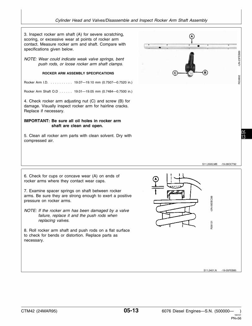
3. Inspect rocker arm shaft (A) for severe scratching,scoring, or excessive wear at points of rocker armcontact. Measure rocker arm and shaft. Compare withspecifications given below.
NOTE: Wear could indicate weak valve springs, bentpush rods, or loose rocker arm shaft clamps.
ROCKER ARM ASSEMBLY SPECIFICATIONS
Rocker Arm I.D. . . . . . . . . . . 19.07—19.10 mm (0.7507—0.7520 in.)
Rocker Arm Shaft O.D . . . . . . 19.01—19.05 mm (0.7484—0.7500 in.)
4. Check rocker arm adjusting nut (C) and screw (B) fordamage. Visually inspect rocker arm for hairline cracks.Replace if necessary.
IMPORTANT: Be sure all oil holes in rocker armshaft are clean and open.
5. Clean all rocker arm parts with clean solvent. Dry withcompressed air.
RG
3802
-U
N-2
3FE
B89
6. Check for cups or concave wear (A) on ends ofrocker arms where they contact wear caps.
7. Examine spacer springs on shaft between rockerarms. Be sure they are strong enough to exert a positivepressure on rocker arms.
NOTE: If the rocker arm has been damaged by a valvefailure, replace it and the push rods whenreplacing valves.
8. Roll rocker arm shaft and push rods on a flat surfaceto check for bends or distortion. Replace parts asnecessary.
R26
131
-UN
-09D
EC
88
S11,2005,MB -19-28OCT92
S11,0401,N -19-05FEB85
Cylinder Head and Valves/Disassemble and Inspect Rocker Arm Shaft Assembly
CTM42 (24MAR95) 05-13 6076 Diesel Engines—S.N. (500000— )160101
PN=56
0513

ASSEMBLE ROCKER ARM SHAFTASSEMBLY
1. Assemble parts on rocker arm shaft opposite removalprocedure.
Make sure rocker arm shaft end plugs (A) are firmlyseated against end of shaft, and washers (B) areinstalled on shaft.
RG
3801
-U
N-2
3FE
B89
MEASURE VALVE RECESS
1. Measure and record valve recess dimensions for allvalves using JDG451 Gauge with D17526CI (English, in.)or D17527CI (Metric, mm) Dial Indicator or KJD10123Gauge and compare measurements to specificationsgiven below.
NOTE: Thoroughly clean all gasket material from cylinderhead combustion face before measuring.
VALVE RECESS SPECIFICATIONS
Valve Recess Below Cylinder Head: Exhaust . . . . . . . . . . . . . . . . . . 1.19—1.70 mm (0.047—0.067 in.) —Maximum Recess . . . . . . . . . . . . . . . . . . . 2.46 mm (0.097 in.)
Intake . . . . . . . . . . . . . . . . . . . 3.35—3.86 mm (0.132—0.152 in.) —Maximum Recess . . . . . . . . . . . . . . . . . . . 4.62 mm (0.182 in.)
NOTE: If measurement does not meet specifications,check valve face angle and valve seat angle. Ifvalve is recessed beyond the maximumspecification, install either new valves, valve seatinserts, or both to obtain proper valve recess.(See REMOVE VALVE SEAT INSERTS ANDMEASURE BORES IN CYLINDER HEAD, later inthis group.)
RG
5250
-U
N-0
6DE
C88
S11,0401,O -19-08MAR94
RG,CTM42,G5,10 -19-28OCT92
Cylinder Head and Valves/Measure Valve Recess
CTM42 (24MAR95) 05-14 6076 Diesel Engines—S.N. (500000— )160101
PN=57
0514

PRELIMINARY CYLINDER HEAD AND VALVE CHECKS
Make preliminary inspection of cylinder head andvalve assembly during disassembly.
Look for the following conditions:
• Sticking Valves:
Carbon deposits on valve stem. Worn valve guides. Scored valve stems. Warped valve stems. Cocked or broken valve springs. Worn or distorted valve seats. Insufficient lubrication.
• Warped, Worn, or Distorted Valve Guides:
Lack of lubrication. Cylinder head distortion. Excessive heat. Unevenly tightened cylinder head cap screws.
• Distorted Cylinder Head and Gasket Leakage:
Loss of cylinder head cap screw torque. Broken cylinder head cap screw. Overheating from low coolant level operation. Insufficient liner standout. Coolant leakage into cylinder causing hydraulic failure of gasket. Leaking aftercooler. Cracked cylinder head. Cracked cylinder liner. Damaged or incorrect gasket. Overpowering or overfueling. Damaged cylinder head or block surfaces. Improper surface finish on cylinder head. Improperly tightened cylinder head cap screws. Faulty gasket installation (misaligned).
• Worn or Broken Valve Seats:
Misaligned valves. Distorted cylinder head. Carbon deposits on seats due to incomplete combustion. Valve spring tension too weak. Excessive heat. Improper valve clearance. Improper valve timing. Incorrect valve or seat installed.
• Burned, Pitted, Worn, or Broken Valves:
Worn or distorted valve seats. Loose Valve Seats Worn valve guides. Insufficient cooling. Cocked or broken valve springs. Improper engine operation. Improper valve train timing. Faulty valve rotators. Warped or distorted valve stems. “Stretched” valves due to excessive spring tension. Warped cylinder head. Bent push rods. Carbon build-up on valve seats. Rocker arm failure. Incorrect valve or seat installed. Incorrect piston-to-valve clearance.
• Improper Valve Clearance:
Inefficient use of fuel. Engine starts harder. Maximum engine power will not be achieved. Shorter service life of valve train. Greater chance for engine to overheat.
• Excessive Recession:
Worn valve guides. Bent valves. Debris passed through valve train.
RG,CTM8,G05,28 -19-08MAR94
Cylinder Head and Valves/Preliminary Cylinder Head and Valve Checks
CTM42 (24MAR95) 05-15 6076 Diesel Engines—S.N. (500000— )160101
PN=58
0515

REMOVE VALVE ASSEMBLY
NOTE: Refer to PRELIMINARY CYLINDER HEAD ANDVALVE CHECKS earlier in this group.
NOTE: Identify all parts for proper assembly in samelocation as removed.
1. Compress JDE138 Valve Spring Compressor (A) overvalve.
2. Remove retaining locks (B).
3. Remove valve spring compressor.
RG
3803
-U
N-2
3FE
B89
4. Remove valve rotators (A) and valve springs (B).
5. Remove exhaust valve stem shields.
6. Remove valves (C) from cylinder head.
RG
3804
-U
N-2
3FE
B89
S11,0401,Q -19-14FEB95
RG,CTM42,G5,27 -19-28OCT92
Cylinder Head and Valves/Remove Valve Assembly
CTM42 (24MAR95) 05-16 6076 Diesel Engines—S.N. (500000— )160101
PN=59
0516

INSPECT AND MEASURE VALVE SPRINGS
1. Inspect valve springs for alignment, wear anddamage.
2. Put springs on a flat surface to see that they aresquare and parallel.
3. Check valve spring tension using D01168AA SpringCompression Tester.
NOTE: Free spring length of 65 mm (2.56 in.) springsdiffer slightly, but compressed height must be thesame.
VALVE SPRING SPECIFICATIONSSpring Load HeightIntake: Open: 810—880 N (182—198 lb-force) . . . . . . . 38.1 mm (1.50 in.) Closed: 345—399 N (78—90 lb-force) . . . . . . . . 52.5 mm (2.07 in.)
Exhaust: Open: 797—867 N (179—195 lb-force) . . . . . . . 38.5 mm (1.52 in.) Closed: 284—338 N (64—76 lb-force) . . . . . . . . 54.5 mm (2.15 in.)
RG
2732
-U
N-2
3FE
B89
T82
054
-UN
-08N
OV
88
INSPECT VALVE ROTATORS AND WEARCAPS
1. Insure that valve rotators (A), if equipped, will turnfreely. Replace if defective.
2. Replace valve wear caps (B) if pitted or worn.
3. Inspect valve retainer locks for excessive wear.Replace as needed.
RG
3491
-U
N-2
3FE
B89
RG,CTM42,G5,11 -19-06SEP94
S11,0401,T -19-14FEB95
Cylinder Head and Valves/Inspect Valve Rotators and Wear Caps
CTM42 (24MAR95) 05-17 6076 Diesel Engines—S.N. (500000— )160101
PN=60
0517

CLEAN VALVES
1. Hold each valve firmly against a soft wire wheel on abench grinder.
2. Make sure all carbon is removed from valve head,face and unplated portion of stem.
IMPORTANT: Any carbon left on the stem will affectalignment in valve refacer if valvesneed to be refaced. Do not use wirewheel on plated portion of valve stem.
INSPECT AND MEASURE VALVES
1. Thoroughly clean and inspect valves to help determineif they can be restored to a serviceable condition.Replace valves that are burned, cracked, eroded, orchipped.
2. Inspect valve retainer lock groove (C) on valve stemfor damage. Also inspect stems for signs of scuffing,which may indicate insufficient valve guide-to-valve stemclearance. Replace if defects are evident.
3. Measure valve head OD (A). Compare valve stem OD(B) with guide ID to determine clearance, as outlinedlater in this group.
VALVE HEAD AND STEM SPECIFICATIONS
A—Valve Head OD: Exhaust . . . . . . . . . . . . . . . . 46.87—47.13 mm (1.845—1.856 in.) Intake . . . . . . . . . . . . . . . . . . 50.87—51.13 mm (2.003—2.013 in.)
B—Valve Stem OD: Exhaust . . . . . . . . . . . . . . . . 9.44—9.46 mm (0.3717—0.3724 in.) Intake . . . . . . . . . . . . . . . . . . 9.46—9.49 mm (0.3724—0.3736 in.)
RG
5795
-U
N-1
2AU
G91
S11,0401,U -19-13MAR92
RG,CTM42,G5,12 -19-03MAY93
Cylinder Head and Valves/Inspect and Measure Valves
CTM42 (24MAR95) 05-18 6076 Diesel Engines—S.N. (500000— )160101
PN=61
0518

4. Use D05058ST Valve Inspection Center to determineif valves are out of round, bent or warped.
VALVE FACE RUNOUT SPECIFICATION
Maximum permissible runout of valve face . . . . . . . . . . . . . . . . . . . . . . . . . . 0.05 mm (0.002 in.)
RG
4234
-U
N-2
3FE
B89
GRIND (REFACE) VALVES
IMPORTANT: Valve grinding should only be done byexperienced personnel familiar withequipment and capable of maintainingrequired specifications.
If necessary to reface valve, grind valve face to an angleof 29.25˚ ± 0.25˚ (A).
IMPORTANT: When valve faces are ground, it isimportant not to nick valvehead-to-stem radius with facing stone.A nick could cause the valve to break.Radius all sharp edges after grinding.
RG
5247
-U
N-1
2AU
G91
INSPECT AND CLEAN CYLINDER HEAD
Inspect all cylinder head passages for restrictions. Headswith restricted or clogged passages can be cleaned bysoaking them in a tank of hot caustic solution.
Scrape all old gasket material from head. Use a poweredwire brush to clean sealing surfaces.
If cylinder head is not put in a chemical hot tank forcleaning, clean with solvent and a brush. Dry withcompressed air and be sure to blow out all passages.
S11,2005,IZ -19-14FEB95
S11,2005,MG -19-20JUL94
S11,2005,KW -19-16AUG94
Cylinder Head and Valves/Inspect and Clean Cylinder Head
CTM42 (24MAR95) 05-19 6076 Diesel Engines—S.N. (500000— )160101
PN=62
0519

CHECK CYLINDER HEAD COMBUSTIONFACE FLATNESS
Check cylinder head flatness using D05012ST PrecisionStraightedge and feeler gauge. Check lengthwise,crosswise, and diagonally in several places.
If any measurement exceeds this specification, thecylinder head must be either resurfaced or replaced.(See MEASURE CYLINDER HEAD THICKNESS, later inthis group.)
CYLINDER HEAD TOP DECK FLATNESS SPECIFICATION
Maximum Out-of-Flat (Over Entire Length or Width) . . . . . . . . . . . 0.102 mm (0.0040 in.)Straightness per any 305 mm (12 in.) Length . . . . . . . . . . . . . . . . . . . . . . 0.025 mm (0.001 in.)
RG
7231
-U
N-0
7SE
P94
RG
7232
-U
N-0
7SE
P94
RG
4629
-U
N-0
6DE
C88
S11,2005,KY -19-14FEB95
Cylinder Head and Valves/Check Cylinder Head Combustion Face Flatness
CTM42 (24MAR95) 05-20 6076 Diesel Engines—S.N. (500000— )160101
PN=63
0520

MEASURE CYLINDER HEAD THICKNESS
Measure head thickness (A) from valve cover gasketrail-to-combustion face.
If cylinder head thickness is less than wear limit. DONOT attempt to resurface. Install a new cylinder head.
NOTE: If necessary to resurface cylinder head, aMAXIMUM of 0.762 mm (0.030 in.) can beground from new part dimension. Remove ONLYwhat is necessary to restore flatness.
IMPORTANT: After resurfacing, check flatness asdescribed earlier and check surfacefinish on combustion face of head.
Check valve recess after grinding. (SeeMEASURE VALVE RECESS, earlier inthis group.) Valve seat or valve facemay be ground to bring thischaracteristic within specification.
CYLINDER HEAD SPECIFICATIONS
Thickness . . . . . . . . . . . . . . 155.45—155.71 mm (6.120—6.130 in.)Wear Limit . . . . . . . . . . . . . . . . . . . . . . . . . . 154.69 mm (6.09 in.)
Combustion Face Surface Finish (AA) . . . . . . . . . 0.015—0.0028 mm(60—110 micro-in.)
Maximum Wave Depth . . . . . . . . . . . . . . . . . 0.008 mm (0.0003 in.)
RG
4421
-U
N-2
3FE
B89
S11,2005,KZ -19-14SEP94
Cylinder Head and Valves/Measure Cylinder Head Thickness
CTM42 (24MAR95) 05-21 6076 Diesel Engines—S.N. (500000— )160101
PN=64
0521

CLEAN VALVE GUIDES
1. Use a D17011BR Valve Guide Cleaning Brush toclean valve guides before inspection or repair.
NOTE: A few drops of light oil or kerosene will help tofully clean the guide.
RG
5346
-U
N-0
6DE
C88
MEASURE VALVE GUIDES
1. Measure valve guides (A) for wear using a telescopegauge (B) and micrometer.
VALVE GUIDE SPECIFICATIONS
I.D. Guide in a New Head . . . . . . . . . . . . . . . . . . . 9.51—9.54 mm(0.3745—0.3755 in.)
New Guide-to-Valve Stem Clearance: Exhaust . . . . . . . . . . . . . . . . . 0.051—0.102 mm (0.002—0.004 in.) Intake . . . . . . . . . . . . . . . . . . 0.025—0.076 mm (0.001—0.003 in.)
NOTE: Worn guides can allow a clearance of 0.15 mm(0.006 in.) and still be acceptable. Worn guidesmay be knurled to return them to specifiedclearance if valve-to-guide clearance is 0.25 mm(0.010 in.) or less. If clearance exceeds 0.25 mm(0.010 in.), install oversize valves.
IMPORTANT: ALWAYS knurl exhaust valve guidesbefore reaming to assure proper valveguide-to-stem clearance.
R23
984
-UN
-09D
EC
88
S11,2005,MY -19-28OCT92
S11,2005,MH -19-03MAY93
Cylinder Head and Valves/Measure Valve Guides
CTM42 (24MAR95) 05-22 6076 Diesel Engines—S.N. (500000— )160101
PN=65
0522

KNURL VALVE GUIDES
1. Use JT05949 (formerly D20002) Valve Guide KnurlerKit to knurl valve guides.
NOTE: Use tool set exactly as directed by themanufacturer.
2. After knurling, ream valve guide to finished size toprovide specified stem-to-guide clearance.
A—KnurlerB—ReamerC—Speed ReducerD—Lubricant
R26
141
-UN
-09D
EC
88
CLEAN AND INSPECT VALVE SEATS
1. Use an electric hand drill with D17024BR WireCleaning Brush or equivalent brush to remove all carbonon valve seats.
2. Check seats for cracks, pits, or excessive wear.
3. Check entire combustion face for rust, scoring, pittingor cracks.
R26
142N
-UN
-09D
EC
88
S11,0401,Z -19-08MAR94
S11,0401,AA -19-28OCT92
Cylinder Head and Valves/Clean and Inspect Valve Seats
CTM42 (24MAR95) 05-23 6076 Diesel Engines—S.N. (500000— )160101
PN=66
0523

MEASURE VALVE SEATS
1. Measure valve seats for proper specifications listedbelow.
2. Using D11010KW Eccentrimeter, measure valve seatrunout (D).
3. If valve seat is not within specification, reconditionvalve seat by grinding or replace valve seat inserts (A) ifreconditioning is not possible. (See GRIND VALVESEATS or INSTALL VALVE SEAT INSERTS, later in thisgroup.)
VALVE SEAT SPECIFICATIONS
Valve Seat Angle (B) . . . . . . . . . . . . . . . . . . . . . . . . . . 30˚ ±0.50˚
Valve Seat Width (C): —Exhaust . . . . . . . . . . . . . . . . . . 2.0—3.8 mm (0.079—0.150 in.) —Intake . . . . . . . . . . . . . . . . . . . . 1.4—3.8 mm (0.055—0.150 in.)
Maximum Valve Seat Runout . . . . . . . . . . . . 0.051 mm (0.0020 in.)
A—Valve Seat InsertB—Valve Seat AngleC—Valve Seat WidthD—Valve Seat Runout
RG
5248
-U
N-0
6DE
C88
S11,2005,MI -19-16SEP94
Cylinder Head and Valves/Measure Valve Seats
CTM42 (24MAR95) 05-24 6076 Diesel Engines—S.N. (500000— )160101
PN=67
0524

GRIND VALVE SEATS
IMPORTANT: Valve seat grinding should only bedone by experienced personnel familiarwith equipment and capable ofmaintaining required specifications.ALWAYS keep work area clean whengrinding valve seats.
Using JT05893 Heavy-Duty Seat GrinderSet, grind valve seats to obtain correctvalve recess in cylinder head. (SeeMEASURE VALVE RECESS earlier inthis group.) Be sure valve guide boresare clean before grinding valve seats.(See CLEAN VALVE GUIDES earlier inthis group.)
If valve seats need grinding, do not grind too long. Onlya few seconds are required to recondition the averagevalve seat. Avoid the tendency to grind off too much. Donot use too much pressure. While grinding, support theweight of the dresser to avoid excessive pressure on thestone.
1. Check the seat width and contact pattern between theseat and valve with bluing. Seat width MUST BEmaintained within specification. Use a vernier caliper orscale to measure seat width. Thoroughly clean seat areaafter grinding and replace valves and valve seat insertsas necessary.
NOTE: Valve seat width can be reduced with anarrowing stone. This will change the angle atthe top of the seat and increase the diameter. Ifvalve seat width is too narrow, valve may burn orerode. Varying the width changes the fine contactbetween valve face and seat.
2. ALWAYS measure valve seat runout after grindingusing D11010KW Eccentrimeter.
VALVE SEAT SPECIFICATIONS
A—Valve Seat InsertB—Valve Seat Angle . . . . . . . . . . . . . . . . . . . . . . . . . . 30˚ ±0.50˚C—Valve Seat Width —Exhaust . . . . . . . . . . . . . . . . . . 2.0—3.8 mm (0.079—0.150 in.) —Intake . . . . . . . . . . . . . . . . . . . 1.4—3.8 mm (0.055—0.150 in.)D—Maximum Valve Seat Runout . . . . . . . . . . 0.051 mm (0.0020 in.)
IMPORTANT: Blend or radius all sharp edges aftergrinding valve seats. Always checkvalve recess in cylinder head aftergrinding as described later.
R26
143N
-UN
-09D
EC
88R
G52
48
-
UN
-06D
EC
88
S11,2005,MJ -19-28OCT92
Cylinder Head and Valves/Grind Valve Seats
CTM42 (24MAR95) 05-25 6076 Diesel Engines—S.N. (500000— )160101
PN=68
0525

REMOVE VALVE SEAT INSERTS ANDMEASURE BORES IN CYLINDER HEAD
In some cases the inside diameter of the valve seat boremay become damaged or oversized and requiremachining. In this case, oversize inserts are available in0.25 mm (0.010 in.) oversize only.
IMPORTANT: Be careful not to damage cylinder headwhen removing seats.
1. Remove valve seat insert (if necessary) withJDE41296 Valve Seat Puller (A). Adjusting screw onpuller may need to be retightened during removal ofinserts.
NOTE: On some engines, removal of valve seat insertswith the JDE41296 Puller may not be possible.An alternate removal method is to weld two orthree short beads (use an arc welder) equidistantfrom each other around the face of insert. Allowseat to cool and carefully pry out the insert(s)with a screwdriver.
IMPORTANT: If an arc welder is used to removevalve seat inserts, protect entirecombustion face and valve throat areafrom weld spatter.
2. After removal of inserts, thoroughly clean area aroundvalve seat bore and inspect for damage or cracks.
RG
5306
-U
N-0
6DE
C88
S11,2005,ML -19-28OCT92
Cylinder Head and Valves/Remove Valve Seat Inserts and Measure Bores
CTM42 (24MAR95) 05-26 6076 Diesel Engines—S.N. (500000— )160101
PN=69
0526
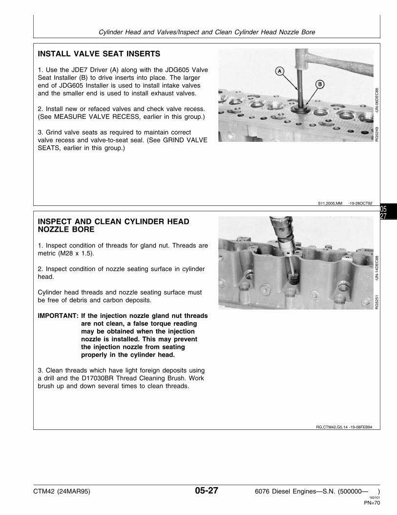
INSTALL VALVE SEAT INSERTS
1. Use the JDE7 Driver (A) along with the JDG605 ValveSeat Installer (B) to drive inserts into place. The largerend of JDG605 Installer is used to install intake valvesand the smaller end is used to install exhaust valves.
2. Install new or refaced valves and check valve recess.(See MEASURE VALVE RECESS, earlier in this group.)
3. Grind valve seats as required to maintain correctvalve recess and valve-to-seat seal. (See GRIND VALVESEATS, earlier in this group.)
RG
5249
-U
N-0
6DE
C88
INSPECT AND CLEAN CYLINDER HEADNOZZLE BORE
1. Inspect condition of threads for gland nut. Threads aremetric (M28 x 1.5).
2. Inspect condition of nozzle seating surface in cylinderhead.
Cylinder head threads and nozzle seating surface mustbe free of debris and carbon deposits.
IMPORTANT: If the injection nozzle gland nut threadsare not clean, a false torque readingmay be obtained when the injectionnozzle is installed. This may preventthe injection nozzle from seatingproperly in the cylinder head.
3. Clean threads which have light foreign deposits usinga drill and the D17030BR Thread Cleaning Brush. Workbrush up and down several times to clean threads.
RG
5251
-U
N-1
4DE
C88
S11,2005,MM -19-28OCT92
RG,CTM42,G5,14 -19-08FEB94
Cylinder Head and Valves/Inspect and Clean Cylinder Head Nozzle Bore
CTM42 (24MAR95) 05-27 6076 Diesel Engines—S.N. (500000— )160101
PN=70
0527

4. Clean threads with heavy foreign deposits or clean updamaged threads using the JDF5 Tap (M28 x 1.5 mm)or an equivalent M28 x 1.5 mm (metric) tap (A). Be sureto start tap straight to avoid possible cross-threading. Alight coat of grease on tap will help collect foreigndeposits on tap and prevent them from falling into thenozzle bore.
RG
5252
-U
N-0
6DE
C88
5. Clean nozzle seating surface by using the JDG609Nozzle Seat Reamer (A) to remove carbon.
6. Blow out debris with compressed air and thoroughlyclean all nozzle bores.
RG
5253
-U
N-0
6DE
C88
CLEAN AND INSPECT PUSH RODS
1. Clean push rods with solvent and compressed air.
2. Check push rods for straightness by rolling on a flatsurface.
3. Inspect contact ends for wear and damage.
4. Replace defective push rods.
T81
233
-UN
-01N
OV
88
INSPECT AND CLEAN VENTILATOR OUTLETHOSE
1. Check ventilator outlet hose (A) on rocker arm coverfor bent or damaged condition. Replace if necessary.
2. Clean ventilator hose if restricted.
RG
5797
-U
N-1
2AU
G91
RG,CTM42,G5,15 -19-22AUG91
S11,2005,NU -19-23AUG91
S11,2005,JN -19-24APR92
RG,CTM42,G5,9 -19-28OCT92
Cylinder Head and Valves/Inspect and Clean Ventilator Outlet Hose
CTM42 (24MAR95) 05-28 6076 Diesel Engines—S.N. (500000— )160101
PN=71
0528

CLEAN AND INSPECT TOP DECK OFCYLINDER BLOCK
1. Remove gasket material, rust, carbon, and otherforeign material from top deck. Gasket surface must beclean.
2. Use compressed air to remove all loose foreignmaterial from cylinders and top deck.
3. Remove cylinder head locating dowels.
4. Clean all cylinder head mounting cap screw holesusing JDG681A or an equivalent 9/16-12 UNC-2A tapabout 114.3 mm (4.5 in.) long. Use compressed air toremove debris and any fluids which may be present inthe cap screw holes.
5. Measure top deck flatness. See MEASURECYLINDER BLOCK in Group 10.
6. Install new cylinder head locating dowel pins incylinder block.
RG
5796
-U
N-1
2AU
G91
RG,CTM42,G5,17 -19-17MAR95
Cylinder Head and Valves/Clean and Inspect Top Deck of Cylinder Block
CTM42 (24MAR95) 05-29 6076 Diesel Engines—S.N. (500000— )160101
PN=72
0529

MEASURE CYLINDER LINER STANDOUT(HEIGHT ABOVE BLOCK)
1. Bolt down liners using cap screws and flat washers inthe seven locations as shown. Flat washers should be atleast 3.18 mm (1/8 in.) thick. Tighten cap screws to 68N·m (50 lb-ft) to achieve an accurate standout reading.
NOTE: Liners having obvious defects must be replaced.
2. Using JDG451 Gauge along with D17526CI (English)or D17527CI (Metric scale) Dial Indicator (B) orKJD10123 Gauge to measure the height (C) of bolteddown liners (A) that are not obviously defective beforeremoval from block (D).
NOTE: Variations in measurement readings may occurwithin one cylinder and/or between adjacentcylinders.
3. Measure each liner in four places, approximately at 1,5, 7 and 11 O’clock positions as viewed from the rear ofthe engine (flywheel end). Record all measurements bycylinder number.
4. Remove any liner that does not meet standoutspecification at any location and install liner shims orreplace piston/liner sets as necessary, as outlined in A—Cylinder Liner
B—Dial IndicatorGroup 10. See INSTALL LINER SHIMS—IF REQUIRED.C—Liner HeightD—Cylinder BlockLINER HEIGHT SPECIFICATIONS
Liner Height Above Block . . . . . . . . . . . . . . . . . . 0.050—0.127 mm(0.002—0.005 in.)
RG
5829
-U
N-1
2AU
G91
RG
5813
-U
N-0
8MA
R94
RG,CTM42,G5,31 -19-16AUG94
Cylinder Head and Valves/Measure Cylinder Liner Standout (Height above Block)
CTM42 (24MAR95) 05-30 6076 Diesel Engines—S.N. (500000— )160101
PN=73
0530

ASSEMBLE VALVE ASSEMBLY
1. Apply AR44402 Valve Stem Lubricant or clean engineoil to valve stems and guides.
NOTE: Exhaust valve stem shields will not seat on valveguide tower; they ride up and down with valvestem.
2. Install reconditioned or new valves (A) in head. Ifvalves are reused, install in same location from whichremoved.
NOTE: Valves must move freely and seat properly.
RG
3806
-U
N-2
3FE
B89
NOTE: There is no top or bottom to valve springs; theymay be installed either way.
3. Position valve springs (B). End of spring must be inmachined counterbore of head. Do not mix valve springs.See INSPECT AND MEASURE VALVE SPRINGS,earlier in this group.
4. Install valve rotators (A) on springs and valves (C).
5. Install valve stem shields on exhaust valve stems. RG
3804
-U
N-2
3FE
B89
6. Compress valve springs with JDE138 Valve SpringCompressor (A) and install retainer locks (B).
NOTE: Install wear caps just before installing rocker armassembly.
RG
3803
-U
N-2
3FE
B89
S11,0401,AK -19-28OCT92
RG,CTM42,G5,28 -19-28OCT92
RG,CTM42,G5,29 -19-28OCT92
Cylinder Head and Valves/Assemble Valve Assembly
CTM42 (24MAR95) 05-31 6076 Diesel Engines—S.N. (500000— )160101
PN=74
0531

7. Strike end of each valve with a soft mallet (A) three orfour times to insure proper seating of the retainer locks.
Repeat procedure for all remaining valves. Remembervalve stem seals are installed onto exhaust valve stemsonly.
8. Measure valve recess as directed earlier in this group.
RG
3807
-U
N-2
3FE
B89
INSTALL CYLINDER HEAD
IMPORTANT: ALWAYS thoroughly inspect newcylinder head gasket for possiblemanufacturing imperfections. Returnany gasket that does not passinspection.
Be sure cylinder head and block gasketsurfaces are clean, dry, and free of anyoil.
1. Put a new head gasket on cylinder block. Do not usesealant on gasket; install dry.
IMPORTANT: If cylinder head is lowered ontocylinder block and you discover thatthe head is not positioned correctly onlocating dowels, remove cylinder headand install a new gasket. DO NOT tryto reposition cylinder head on the samegasket again since the fire ring willpossibly be damaged.
2. Lower cylinder head everly to correct position on blockusing appropriate lifting equipment. Make sure that headis positioned correctly over dowels.
RG
5245
-U
N-0
6DE
C88
RG,CTM42,G5,30 -19-28OCT92
RG,CTM42,G5,40 -19-14FEB95
Cylinder Head and Valves/Install Cylinder Head
CTM42 (24MAR95) 05-32 6076 Diesel Engines—S.N. (500000— )160101
PN=75
0532

CYLINDER HEAD CAP SCREW TYPES
A—ASTM Grade 180 Flanged-Head B—Flanged-Head Marked“SPECIAL”
One of the two cylinder head cap screws shown willbe found on the engine, depending upon when theengine was built.
IMPORTANT: Cylinder head cap screw torquespecifications and tighteningprocedures vary depending upon thegrade or type of cap screw used,and the cylinder block castingnumber.
Cylinder block casting numbers R116070, R119995,R119996, R119997, R119998 and R119999 useGrade 180 flanged-head cylinder head cap screws.These cap screws must be tightened using the“Torque-Turn” method. See TIGHTENFLANGED-HEAD CYLINDER HEAD CAP SCREWSlater in this group.
For cylinder blocks with casting numbers R122736,R122737, R122738, R122739, R122740 andR122741, the early engines were built with Grade180 flanged-head cylinder head cap screws, and laterengines are built with cylinder head cap screwsmarked “SPECIAL”. For service of these engines,either type of cylinder head cap screw can be used,although use of “SPECIAL” cylinder head cap screwsis recommended.
Grade 180 flanged-head cylinder head cap screwsmust be tightened using the “TORQUE-TURN”method. See TIGHTEN FLANGED-HEAD CYLINDERHEAD CAP SCREWS — GRADE 180, later in thisgroup.
Cylinder head cap screws marked “SPECIAL” mustbe tightened using the “TORQUE-TO-YIELD” method.See TORQUE-TO-YIELD FLANGED-HEAD CAPSCREWS—GRADE 180 MARKED “SPECIAL” later inthis group.
IMPORTANT: DO NOT re-use cylinder head capscrews marked “SPECIAL”, theymay be used only one time.
RG
7226
-U
N-2
2JU
L94
RG,CTM42,G5,41 -19-14FEB95
Cylinder Head and Valves/Cylinder Head Cap Screw Types
CTM42 (24MAR95) 05-33 6076 Diesel Engines—S.N. (500000— )160101
PN=76
0533

CLEAN, INSPECT AND INSTALL CYLINDERHEAD CAP SCREWS
IMPORTANT: All SAE Grade 180 flanged-head capscrews can be reused if they passinspection EXCEPT for theflanged-head cap screws marked“SPECIAL”. These cap screws can beused only one time and only oncylinder blocks with casting numbersR116070, R119995, R119996, R119997,R119998, and R119999.
1. Clean entire length of cap screws (if reusing) toremove rust and scale using a wire brush and solvent.Dry cap screws with compressed air.
2. Inspect cap screws for corrosion damage andcondition of threads. ANY CAP SCREW WITHCORROSION OR OTHER IMPERFECTIONS MUST BEREPLACED.
IMPORTANT: DO NOT use multi-viscosity oilstolubricate cap screws. Only SAE30engine oil may be used.
3. Dip entire cap screw in clean SAE30 engine oil. Allowexcess oil to drip off.
Arrow (A) points toward front of engine.
4. Install cap screws in proper location.
Use the following cap screws in location as shown:
Cap Screw Length Location on Cylinder Head
134 mm (5.2 in.) . . . . . . . . . . . . . . . . . . . . . . . . . . . 2, 3, 4, 5, 6, 7149 mm (5.9 in.) . . . . . . . . . . . . . . . . . . . . . . . . 23, 25, 17, 21, 19175 mm (6.9 in.) . . . . . . . . . . . . . . . . . . 1, 15, 14, 13, 12, 11, 10, 8203 mm (8.0 in.) . . . . . . . . . . . . . . . . . . . . 16, 20, 22, 18, 26, 24, 9
RG
4471
-U
N-2
8FE
B94
RG,CTM42,G5,42 -19-17MAR95
Cylinder Head and Valves/Clean, Inspect and Install Cylinder Head Cap Screws
CTM42 (24MAR95) 05-34 6076 Diesel Engines—S.N. (500000— )160101
PN=77
0534

TORQUE-TURN FLANGED-HEAD CAPSCREWS—GRADE 180
Arrow (A) points toward front of engine.
• Using line scribe method to TORQUE-TURNcylinder head cap screws:
IMPORTANT: DO NOT use multi-viscosity oils tolubricate cap screws.
1. Lubricate cap screws with clean SAE30 engine oil andinstall in their proper locations as outlined previously.
2. Tighten cap screw No. 17 to 100 N·m (75 lb-ft) first.Tighten all remaining cap screws to 100 N·m (75 lb-ft),beginning with No. 1 and proceed sequentially.
3. Retighten all cap screws to 125 N·m (95 lb-ft)beginning with No. 1.
4. Make 90˚ reference marks (A,B) on socket.
5. Install socket on cap screw No. 1 and make areference mark on cylinder head that aligns withreference mark (A) on socket.
6. Turn cap screw 90˚—100˚ until reference mark oncylinder head aligns with reference mark (B) on socket.
7. Repeat Steps 5 and 6 on all remaining cap screws.
• Using JT05993 Torque Angle Gauge:
After lubricating and tightening cylinder head cap screws(in proper sequence) according to steps 1, 2, and 3listed above, follow directions provided with gauge andTORQUE-TURN each cap screw 90˚—100˚, beginningwith cap screw No. 1 and sequentially proceed thru toNo. 26.
RG7136 -UN-21FEB94
RG
4471
-U
N-2
8FE
B94
RG
7138
-U
N-2
8FE
B94
RG,CTM42,G5,36 -19-14FEB95
Cylinder Head and Valves/Clean, Inspect and Install Cylinder Head Cap Screws
CTM42 (24MAR95) 05-35 6076 Diesel Engines—S.N. (500000— )160101
PN=78
0535

TORQUE-TO-YIELD FLANGED-HEAD CAPSCREWS—GRADE 180 MARKED “SPECIAL”
Arrow (A) points toward front of engine.
IMPORTANT: DO NOT use multi-viscosity oils tolubricate cap screws.
1. Lubricate cap screws with clean SAE30 engine oil andinstall in their proper locations as outlined previously.
2. Tighten cap screw No. 17 to 80 N·m (60 lb-ft).Sequentially (start at cap screw No. 1 and proceedthrough cap screw No. 26) tighten all cap screws to 80N·m (60 lb-ft).
3. Using an oil proof pen, pencil, or marker, draw a lineparallel to the crankshaft across the entire top of eachcap screw head. This line will be used as a referencemark.
IMPORTANT: If a cap screw is accidentally tightenedmore than 90˚ in any one sequence, DONOT loosen cap screw but makeadjustments in the next tighteningsequence.
4. Sequentially (start at cap screw No. 1 and proceedthrough cap screw No. 26) turn each cap screw 90˚.Line on top of cap screw will be perpendicular tocrankshaft.
5. Again, sequentially (start at cap screw No. 1 andproceed through cap screw No. 26) turn each cap screw90˚. Line on top of cap screw will now be parallel tocrankshaft.
IMPORTANT: Cap screws MUST NOT be tightenedmore than a total of 270˚ ±5˚.
6. Finally, sequentially (start at cap screw No. 1 andproceed through cap screw No. 26) turn each cap screw90˚, SO THAT LINE ON TOP OF CAP SCREW IS ASCLOSE AS POSSIBLE TO BEING PERPENDICULARTO THE CRANKSHAFT. It is not necessary to obtain thefinal turn in one swing of the wrench. TOTAL AMOUNTOF TURN FROM STEPS 4, 5, AND 6 IS 270˚ ±5˚.
RG
4471
-U
N-2
8FE
B94
RG
7139
-U
N-0
1MA
Y94
RG,CTM1,G5,4 -19-09AUG94
Cylinder Head and Valves/Torque-To-Yield Special Flanged-Head Cap Screws
CTM42 (24MAR95) 05-36 6076 Diesel Engines—S.N. (500000— )160101
PN=79
0536

INSTALL ROCKER ARM ASSEMBLY
1. Install push rods (A) in holes from which removed.
2. Install wear caps (B) on valves, making certain capsrotate freely.
RG
3809
-U
N-2
3FE
B89
3. Make sure spring pin (A) engages with hole (B) inshaft.
RG5793 -UN-09AUG91
4. Install shaft clamps (B) and all six cap screws (A).Tighten cap screws to 75 N·m (55 lb-ft).
RG
3810
-U
N-2
3FE
B89
S11,2005,HT -19-12JUL94
RG,CTM42,G5,20 -19-07AUG91
Cylinder Head and Valves/Install Rocker Arm Assembly
CTM42 (24MAR95) 05-37 6076 Diesel Engines—S.N. (500000— )160101
PN=80
0537
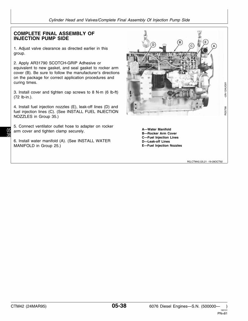
COMPLETE FINAL ASSEMBLY OFINJECTION PUMP SIDE
1. Adjust valve clearance as directed earlier in thisgroup.
2. Apply AR31790 SCOTCH-GRIP Adhesive orequivalent to new gasket, and seal gasket to rocker armcover (B). Be sure to follow the manufacturer’s directionson the package for correct application procedures andcuring times.
3. Install cover and tighten cap screws to 8 N·m (6 lb-ft)(72 lb-in.).
4. Install fuel injection nozzles (E), leak-off lines (D) andfuel injection lines (C). (See INSTALL FUEL INJECTIONNOZZLES in Group 35.)
5. Connect ventilator outlet hose to adapter on rockerA—Water Manifoldarm cover and tighten clamp securely.B—Rocker Arm CoverC—Fuel Injection Lines
6. Install water manifold (A). (See INSTALL WATER D—Leak-off LinesE—Fuel Injection NozzlesMANIFOLD in Group 25.)
RG
5798
-U
N-1
2AU
G91
RG,CTM42,G5,21 -19-28OCT92
Cylinder Head and Valves/Complete Final Assembly Of Injection Pump Side
CTM42 (24MAR95) 05-38 6076 Diesel Engines—S.N. (500000— )160101
PN=81
0538

COMPLETE FINAL ASSEMBLY ON EXHAUSTMANIFOLD SIDE
NOTE: Apply PT569 NEVER-SEEZ Compound orequivalent to all exhaust manifold cap screws,except 6076 HRW 33, 34, and 35 engines. Also,intake manifold is installed before exhaustmanifold on these engines.
1. Install front exhaust manifold using new gaskets. Donot tighten cap screws until sealing ring (A) and rearexhaust manifold is installed.
2. Install rear exhaust manifold using new gaskets andsealing ring.
3. Tighten cap screws in sequence shown in bottomillustration to 47 N·m (35 lb-ft).
4. Install turbocharger oil return pipe, using a newO-ring.
RG
5799
-U
N-1
2AU
G91
RG
5800
-U
N-1
2AU
G91
RG
6338
-U
N-0
3AU
G92
RG,CTM42,G5,22 -19-14FEB95
Cylinder Head and Valves/Complete Final Assembly On Exhaust Manifold Side
CTM42 (24MAR95) 05-39 6076 Diesel Engines—S.N. (500000— )160101
PN=82
0539

5. On 6076T and 6076H Engines, using new gasketsinstall intake manifold (A). Tighten cap screws to 47 N·m(35 lb-ft).
6. On 6076T Engines, install intake coupling (B). Do nottighten clamps.
7. On 6076T and 6076H Engines, install turbocharger(C), adapter (D), and exhaust elbow (E). (See INSTALLTURBOCHARGER in Group 30.)
8. Position intake adapter with turbocharger and intakemanifold and tighten clamps securely.
A—Intake ManifoldB—Intake CouplingC—TurbochargerD—Turbocharger AdapterE—Exhaust Elbow
RG
5801
-U
N-1
2AU
G91
9. On 6076A Engines, use new gaskets (A) and installintake manifold (B). Tighten cap screws to 47 N·m (35lb-ft).
RG
5802
-U
N-1
3AU
G91
10. On 6076A Engines, using new gaskets and O-rings,install aftercooler and cover (A). (See INSTALL INTAKEMANIFOLD AND AFTERCOOLER in Group 30.)
RG
5803
-U
N-1
3AU
G91
RG,CTM42,G5,23 -19-16AUG94
RG,CTM42,G5,24 -19-22AUG91
RG,CTM42,G5,25 -19-06SEP91
Cylinder Head and Valves/Complete Final Assembly On Exhaust Manifold Side
CTM42 (24MAR95) 05-40 6076 Diesel Engines—S.N. (500000— )160101
PN=83
0540

11. Install water inlet (A) and water outlet (C) hoses.Tighten hose clamps securely.
12. Install aneroid line (B), if equipped, and tightensecurely.
13. Install turbocharger (D) with couplings. Tighten capscrews to 47 N·m (35 lb-ft). (See INSTALLTURBOCHARGER in Group 30.)
14. If engine oil was drained from crankcase, install newoil filter and fill with clean oil of correct grade andviscosity. (See DIESEL ENGINE OIL in Group 02.)
15. Fill cooling system with clean coolant. (See ENGINECOOLANT SPECIFICATIONS in Group 02.)
16. Perform engine break-in as outlined later in thisgroup. (See PERFORM ENGINE BREAK-IN.)
A—Water Inlet HoseB—Aneroid LineC—Water Outlet Tube and HoseD—Turbocharger
RG
5885
-U
N-1
3AU
G91
RG,CTM42,G5,32 -19-28OCT92
Cylinder Head and Valves/Complete Final Assembly On Exhaust Manifold Side
CTM42 (24MAR95) 05-41 6076 Diesel Engines—S.N. (500000— )160101
PN=84
0541

PERFORM ENGINE BREAK-IN
1. Run engine at slow idle no load for 2 minutes. Checkfor liquid leaks.
2. Increase RPM to fast idle, then load down to 50 rpmabove rated speed for 20 minutes.
NOTE: Dynamometer is the preferred load control, butengine can be loaded by matching drag loads togear selection.
3. Recheck valve clearance and adjust as necessary.(See CHECK AND ADJUST VALVE CLEARANCE,earlier in this group.)
4. Install rocker arm cover gasket and cover. Tightenrocker arm cover cap screws to 8 N·m (6 lb-ft) (72lb-in.). (See COMPLETE FINAL ASSEMBLY OFINJECTION PUMP SIDE OF ENGINE, earlier in thisgroup.)
Retorque of cylinder head cap screws after enginebreak-in is not required.
IMPORTANT: After engine break-in, follow ALLrecommended hourly service intervalsoutlined in your Operator’s Manual.
RG,CTM6,G05,5 -19-14SEP94
Cylinder Head and Valves/Perform Engine Break-In
CTM42 (24MAR95) 05-42 6076 Diesel Engines—S.N. (500000— )160101
PN=85
0542

SPECIAL OR ESSENTIAL TOOLS
NOTE: Order tools according to information given in theU.S. SERVICE-GARD™ Catalog or in theEuropean Microfiche Tool Catalog (MTC).
Cylinder Liner Puller . . . . . . . . . . . . . . D01062AA(or D01073AA)
Remove cylinder liners.
RG
5019
-U
N-2
3AU
G88
Flexible Cylinder Hone . . . . . . . . . . . . D17005BR
Hone cylinder liners.
RG5074 -UN-23AUG88
O-Ring Groove Cleaning Brush . . . . . . . D17015BR
Clean cylinder liner O-ring groove in block.
RG
5075
-U
N-2
3AU
G88
Dial Indicator . . . . . . . . . . . . . (English, in.) D17526CIor (Metric, mm ) D17527CI
Use with JDG451 to measure valve recess and cylinderliner height-to-cylinder block top deck.
RG
6246
-U
N-2
7MA
R92
DX,TOOLS -19-05JUN91
S53,D01062,AA -19-07AUG91
S53,D17005,BR -19-07APR88
S53,D17015,BR -19-25MAR91
RG,D17526CI -19-29OCT92
Group 10Cylinder Block, Liners, Pistons and Rods
CTM42 (24MAR95) 10-1 6076 Diesel Engines—S.N. (500000— )160101
PN=86
101

Ring Groove Wear Gauge . . . . . . . . . . . . . JDE55
Check wear of keystone ring groove on pistons.
RG5076 -UN-23AUG88
Piston Ring Expander . . . . . . . . . . . . . . . . JDE93
Remove and install piston rings.
RG5077 -UN-23AUG88
Piston Ring Compressor . . . . . . . . . . . . . . JDE96
Compress rings while installing pistons.
RG5031 -UN-23AUG88
Connecting Rod Bushing Service Set . . . . . JDE98A
Remove and install connecting rod bushings.
Set consists of: 1—Cup . . . . . . . . . . . . . . . . . . . . . . . JDE98-1 2—Driver . . . . . . . . . . . . . . . . . . . . . . JDE98-2 3—Pilot . . . . . . . . . . . . . . . . . . . . . . . JDE98-3 4—Driver . . . . . . . . . . . . . . . . . . . . . . JDE98-4 5—Driver . . . . . . . . . . . . . . . . . . . . . . JDE98-5 6—Pilot . . . . . . . . . . . . . . . . . . . . . . . JDE98-6 7—Driver . . . . . . . . . . . . . . . . . . . . . . JDE98-7 8—Cup . . . . . . . . . . . . . . . . . . . . . . . JDE98-8 9—Pilot . . . . . . . . . . . . . . . . . . . . . . . JDE98-9 10—Remover Bushing . . . . . . . . . . . . JDE98-10 Forcing Screw . . . . . . . . . . . . . . . . STD36104
RG
5078
-U
N-1
6FE
B94
Connecting Rod Bushing Service Set . . . . . JDG337
Use with JDE98A Bushing Service Set to remove andinstall connecting rod bushings.
RG5079 -UN-25JUN94
S53,JDE55 -19-25MAR91
S53,JDE93 -19-17FEB87
S53,JDE96 -19-25MAR87
S53,JDE98A -19-16AUG94
S53,JDG337,A -19-29JUL94
Cylinder Block, Liners, Pistons and Rods/Special or Essential Tools
CTM42 (24MAR95) 10-2 6076 Diesel Engines—S.N. (500000— )160101
PN=87
102

Tap . . . . . . . . . . . . . . . . . . . . . . . . . . . . JDG681A
Used to restore threaded holes in cylinder block forcylinder head cap screws.
RG5100 -UN-23AUG88
Torque Angle Gauge . . . . . . . . . . . . . . . . . . JT05993
Used to TORQUE-TURN flanged-head cylinder head andconnecting rod cap screws.
RG
5698
-U
N-2
7AU
G90
SERVICE EQUIPMENT AND TOOLS
NOTE: Order tools from the U.S. SERVICEGARD™ Catalog or from the European Microfiche Tool Catalog(MTC). Some tools may be available from a local supplier.
Name Use
D05012ST Precision “Bevelled Edge” Straightedge Check cylinder block flatness
Piston Ring Groove Cleaner Clean piston ring grooves
Cylinder Bore Ridge Reamer Remove carbon from liner bore
OTHER MATERIAL
Name Use
AR54749 Soap Lubricant Coat O-rings on cylinder liners.
PLASTIGAGE Determine connecting rod bearing-to-journaloil clearance.
RG,JDG681A -19-17MAR95
RG,JT05993 -19-22AUG91
RG,CTM61,G10,6 -19-04AUG94
S11,2010,BS -19-08AUG94
Cylinder Block, Liners, Pistons and Rods/Other Material
CTM42 (24MAR95) 10-3 6076 Diesel Engines—S.N. (500000— )160101
PN=88
103

CYLINDER BLOCK, LINERS, PISTONS, AND RODS SPECIFICATIONS
ITEM SPECIFICATION WEAR LIMIT
Cylinder Liner Height Above Block . . . . . . . . . . . . . . . . . . . . . . . . . . . . 0.050—0.127 mm ——
(0.002—0.005 in.) ——
Maximum Piston Protrusion Above Block . . . . . . . . . . . 0.051—0.787 mm ——(0.002—0.031 in.) ——
Piston Oil Control Ring-to- Groove Clearance . . . . . . . . . . . . . . . . . . . . . . . . 0.064—0.102 mm 0.165 mm
(0.0025—0.0040 in.) (0.0065 in.)Piston Compression Ring End Gap: Pistons Stamped RE50868 No. 1 . . . . . . . . . . . . . . . . . . . . . . . . . . . . . . . 0.43—0.69 mm ——
(0.017—0.027 in.) —— No. 2 . . . . . . . . . . . . . . . . . . . . . . . . . . . . . . . 0.63—0.89 mm ——
(0.025—0.035 in.) —— Pistons Stamped RE57512 No. 1 . . . . . . . . . . . . . . . . . . . . . . . . . . . . . . . 0.43—0.69 mm ——
0.017—0.027 in.) —— No. 2 . . . . . . . . . . . . . . . . . . . . . . . . . . . . . . . 1.27—1.52 mm ——
(0.050—0.060 in.) ——
Piston OD: —19.1 mm (0.75 in.) from Bottom of Skirt Engine Serial No. . . . . . . . . . . . . . . . . . . . . . . . . 115.771—115.789 mm ——
(4.5579—4.5586 in.)
Piston-to-Liner Clearance at Bottom of Skirt: Engine Serial No. . . . . . . . . . . . . . . . . . . . . . . . . 0.076—0.124 mm 0.152 mm
(0.0030—0.0049 in.) (0.0060 in.)
Cylinder Liner ID . . . . . . . . . . . . . . . . . . . . . . . . . . . 115.865—115.895 mm ——(4.5616—4.5628 in.) ——
OD . . . . . . . . . . . . . . . . . . . . . . . . . 127.94—128.24 mm ——(5.037—5.049 in.) ——
Cylinder Liner Thickness . . . . . . . . . . . . . . . . . . . . . 6.05—6.15 mm ——(0.238—0.242 in.) ——
Cylinder Liner Packing Step Dimension . . . . . . . . . . . . 1.45—1.55 mm ——(0.057—0.061 in.) ——
Cylinder Liner Maximum Taper . . . . . . . . . . . . . . . . . 0.051 mm ——(0.0020 in.) ——
RG,CTM42,G10,25-19-17MAR95
Cylinder Block, Liners, Pistons and Rods/Cylinder Block, Liners, Pistons, and Rods Specifications
CTM42 (24MAR95) 10-4 6076 Diesel Engines—S.N. (500000— )160101
PN=89
104
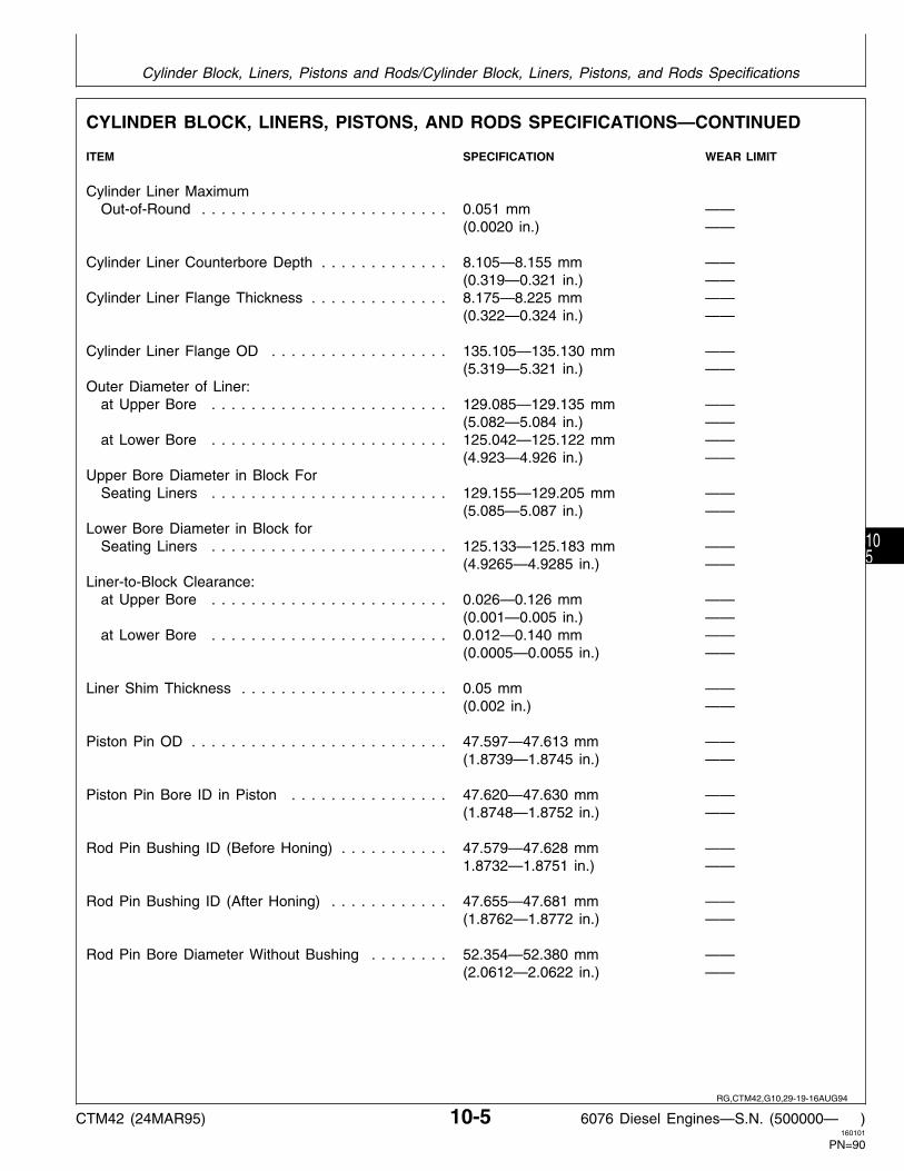
CYLINDER BLOCK, LINERS, PISTONS, AND RODS SPECIFICATIONS—CONTINUED
ITEM SPECIFICATION WEAR LIMIT
Cylinder Liner Maximum Out-of-Round . . . . . . . . . . . . . . . . . . . . . . . . . 0.051 mm ——
(0.0020 in.) ——
Cylinder Liner Counterbore Depth . . . . . . . . . . . . . 8.105—8.155 mm ——(0.319—0.321 in.) ——
Cylinder Liner Flange Thickness . . . . . . . . . . . . . . 8.175—8.225 mm ——(0.322—0.324 in.) ——
Cylinder Liner Flange OD . . . . . . . . . . . . . . . . . . 135.105—135.130 mm ——(5.319—5.321 in.) ——
Outer Diameter of Liner: at Upper Bore . . . . . . . . . . . . . . . . . . . . . . . . 129.085—129.135 mm ——
(5.082—5.084 in.) —— at Lower Bore . . . . . . . . . . . . . . . . . . . . . . . . 125.042—125.122 mm ——
(4.923—4.926 in.) ——Upper Bore Diameter in Block For Seating Liners . . . . . . . . . . . . . . . . . . . . . . . . 129.155—129.205 mm ——
(5.085—5.087 in.) ——Lower Bore Diameter in Block for Seating Liners . . . . . . . . . . . . . . . . . . . . . . . . 125.133—125.183 mm ——
(4.9265—4.9285 in.) ——Liner-to-Block Clearance: at Upper Bore . . . . . . . . . . . . . . . . . . . . . . . . 0.026—0.126 mm ——
(0.001—0.005 in.) —— at Lower Bore . . . . . . . . . . . . . . . . . . . . . . . . 0.012—0.140 mm ——
(0.0005—0.0055 in.) ——
Liner Shim Thickness . . . . . . . . . . . . . . . . . . . . . 0.05 mm ——(0.002 in.) ——
Piston Pin OD . . . . . . . . . . . . . . . . . . . . . . . . . . 47.597—47.613 mm ——(1.8739—1.8745 in.) ——
Piston Pin Bore ID in Piston . . . . . . . . . . . . . . . . 47.620—47.630 mm ——(1.8748—1.8752 in.) ——
Rod Pin Bushing ID (Before Honing) . . . . . . . . . . . 47.579—47.628 mm ——1.8732—1.8751 in.) ——
Rod Pin Bushing ID (After Honing) . . . . . . . . . . . . 47.655—47.681 mm ——(1.8762—1.8772 in.) ——
Rod Pin Bore Diameter Without Bushing . . . . . . . . 52.354—52.380 mm ——(2.0612—2.0622 in.) ——
RG,CTM42,G10,29-19-16AUG94
Cylinder Block, Liners, Pistons and Rods/Cylinder Block, Liners, Pistons, and Rods Specifications
CTM42 (24MAR95) 10-5 6076 Diesel Engines—S.N. (500000— )160101
PN=90
105

CYLINDER BLOCK, LINERS, PISTONS, AND RODS SPECIFICATIONS—CONTINUED
ITEM SPECIFICATION WEAR LIMIT
Rod Pin-to-Bushing Oil Clearance . . . . . . . . . . . . . 0.042—0.084 mm 0.102 mm(0.0017—0.0033 in.) (0.0040 in.)
Rod-to-Pin Bushing Press Fit Specification . . . . . . . 0.084—0.147 mm ——(0.0033—0.0058 in.) ——
Connecting Rod Bore Without Bearings . . . . . . . . . 81.051—81.077 mm ——(3.191—3.192 in.) ——
Connecting Rod Bearing Assembled ID . . . . . . . . . 76.21—76.26 mm ——(3.0004—3.0024 in.) ——
Crankshaft Rod Journal OD . . . . . . . . . . . . . . . . . 76.15—76.18 mm ——(2.9980—2.9992 in.) ——
Bearing-to-Journal Clearance . . . . . . . . . . . . . . . . 0.030—0.110 mm ——(0.0012—0.0044 in.) ——
Maximum Connecting Rod/Cap Gap . . . . . . . . . . . 0.254 mm (0.0100 in.) ——
Maximum Connecting Rod Out-of-Round . . . . . . . . 0.025 mm (0.0010 in.) ——
Centerline of Main Bearing Bore-to- Top Deck of Cylinder Block . . . . . . . . . . . . . . . 352.35—352.50 mm ——
(13.872—13.878 in.) ——
Camshaft Bushing Bore in Block . . . . . . . . . . . . . . 69.987—70.013 mm ——(2.7554—2.7564 in.) ——
Maximum Runout of Camshaft Bushing Bore in Block . . . . . . . . . . . . . . . . . . . . . . . . . 0.038 mm (0.0015 in.) ——
New Camshaft Bushing-to-Journal Clearance . . . . . 0.063—0.115 mm ——(0.0025—0.0045 in.) ——
Camshaft Bushing ID . . . . . . . . . . . . . . . . . . . . . 67.076—67.102 mm ——(2.6408—2.6418 in.) ——
Cylinder Block Top Deck: Maximum Out-of-Flat Over Entire Length or Width . . . . . . . . . . . . . . . . . . . . . . 0.10 mm (0.004 in.) —— Straightness per Any 305 mm (12 in.) Length . . . . . . . . . . . . . . . . . . . . . . . . . . . . . 0.025 mm (0.001 in.) ——
Centerline of Rod Pin Bore-to-Centerline of Crankshaft Journal Bore . . . . . . . . . . . . . . . . 222.20—222.30 mm ——
(8.748—8.752 in.) ——
RG,CTM42,G10,20-19-14FEB95
Cylinder Block, Liners, Pistons and Rods/Cylinder Block, Liners, Pistons, and Rods Specifications
CTM42 (24MAR95) 10-6 6076 Diesel Engines—S.N. (500000— )160101
PN=91
106

CYLINDER BLOCK, LINERS, PISTONS, AND RODS SPECIFICATIONS—CONTINUED
TORQUES
Connecting Rod Cap Screws: Initial * . . . . . . . . . . . . . . . . . . . . . . . . . . . . . . . . . . . . . . . . . . . . . . . . . . . . . . . . 27 N·m (20 lb-ft) Final (All Cap Screws) . . . . . . . . . . . . . . . . . . . . . . . . . . . . . . . . . . . . . . . . . . . . . . 75 N·m (55 lb-ft)
Plus 90—100˚
Piston Cooling Orifices into Cylinder Block . . . . . . . . . . . . . . . . . . . . . . . . . . . . . . . . . . . 9.6—12.4 N·m(85—110 lb-in.)
Cylinder Liner Cap Screws (for Checking Liner Standout) . . . . . . . . . . . . . . . . . . . . . . . . . . . . . . . . . . . . . . . . . . 68 N·m (50 lb-ft)
* See INSTALL PISTONS AND CONNECTING RODS, later in thisgroup, before tightening cap screws. RG,CTM42,G10,39-19-16AUG94
Cylinder Block, Liners, Pistons and Rods/Cylinder Block, Liners, Pistons, and Rods Specifications
CTM42 (24MAR95) 10-7 6076 Diesel Engines—S.N. (500000— )160101
PN=92
107

PRELIMINARY LINER, PISTON AND ROD CHECKS
• Scuffed or Scored Pistons:
Insufficient lubrication.Insufficient cooling.Improper piston-to-liner clearance.Coolant leakage in crankcase.Misaligned or bent connecting rod.Improperly installed piston.Low oil level.Improper operation.Incorrect connecting rod bearing clearance.Carbon build-up in ring groove.Improper break-in.Worn piston.Contaminated oil.Distorted cylinder liner.
• Worn or Broken Compression Rings:
Insufficient lubrication.Insufficient cooling.Improper ring installation.Improper combustion.Improper timing.Abrasives in combustion chamber.
• Clogged Oil Control Ring:
Improper oil.Excessive Blow-by.Contaminated oil.Improper periodic service.Low operating temperature.
• Dull Satin Finish and Fine Vertical Scratches onRings:
Dirt and abrasive in air intake system.
• Stuck Rings:
Improper oil classification.Improper periodic service.Poor operating conditions.Coolant leakage in crankcase.Excessive cylinder liner taper.
• Cylinder Liner Wear and Distortion:
Incorrectly installed compression rings.Insufficient lubrication.Uneven cooling around liner.Improper piston-to-liner clearance.Liner bore damage.
• Warped Cylinder Block:
Insufficient cooling.
• Broken Connecting Rod:
Inadequate piston-to-liner clearance.Worn connecting rod bearing.Distorted cylinder liner.Piston pin failure.
• Piston Pin and Snap Ring Failure:
Misaligned connecting rod.Excessive crankshaft end play.Incorrect snap rings.
• Mottled, Grayish or Pitted Compression Rings:
Internal coolant leaks.
CTM8,GR10,37 -19-17AUG94
Cylinder Block, Liners, Pistons and Rods/Preliminary Liner, Piston, and Rod Checks
CTM42 (24MAR95) 10-8 6076 Diesel Engines—S.N. (500000— )160101
PN=93
108

REMOVE PISTONS AND CONNECTINGRODS
The engine does not always have to be removed fromthe machine to service the pistons and connecting rods.If engine is to be removed, see your Machine TechnicalManual.
N CAUTION: DO NOT drain engine coolant untilthe temperature is below operatingtemperature. Then slowly loosen water pumpdrain valve (A) and block drain valve (B) torelieve any pressure.
IMPORTANT: Both water pump drain valve and blockdrain valve must be opened tocompletely drain both sides of theengine.
1. Drain all coolant and engine oil.
RG
5836
-U
N-2
8AU
G91
NOTE: If engine is to be completely disassembled, followDISASSEMBLY SEQUENCE in Group 04.
2. Remove cylinder head. (See REMOVE CYLINDERHEAD in Group 05.)
3. Remove oil pan and oil pump. (See REMOVEENGINE OIL PUMP in Group 20.)
A—#1 Keystone Compression RingB—#2 Keystone Compression RingC—Oil Control Ring with ExpanderD—Snap Ring (2 used)E—PistonF—Piston PinG—Piston Pin BushingH—Connecting RodI—BearingsJ—Connecting Rod CapK—Special Cap Screw R
G36
57
-
UN
-13D
EC
88
RG,CTM42,G10,19-19-29OCT92
RG,CTM42,G10,30-19-14FEB95
Cylinder Block, Liners, Pistons and Rods/Remove Pistons and Connecting Rods
CTM42 (24MAR95) 10-9 6076 Diesel Engines—S.N. (500000— )160101
PN=94
109

4. Use approximately 51 mm (2.0 in.) long cap screws(A) and 5/8 in. ID x 1-3/4 in. OD x 3.18 mm (1/8 in.)thick washers (B) to bolt down cylinder liners (C) in theseven locations as shown. Tighten cap screws to 68 N·m(50 lb-ft).
NOTE: Do not rotate crankshaft with cylinder headremoved unless liners are bolted down. Boltliners down before removing pistons.
IMPORTANT: Cap screws and washers must betightened to the above specification toachieve an accurate reading whenchecking liner standout (height aboveblock).See MEASURE LINERSTANDOUT (HEIGNT ABOVE BLOCK),later in this group.
As the cylinder liner wears, a ridge is formed at the topof piston ring travel zone. If this ridge gets too high,pistons and rings can be damaged when they areremoved. Remove any ridge from liner bores with ascraper or ridge reamer before removing pistons.
5. Before removing pistons, visually inspect condition ofcylinder liners with pistons at bottom dead center “BDC”.Liners will require replacement if:
—The crosshatch honing pattern is not visibleimmediately below the top ring turn around area.
—Liners are pitted or contain deep vertical scratches thatcan be detected by the fingernail.
No further inspection is required if any one of the aboveconditions are found.
RG
3819
-U
N-0
7DE
C88
RG,CTM42,G10,41-19-14FEB95
Cylinder Block, Liners, Pistons and Rods/Remove Pistons and Connecting Rods
CTM42 (24MAR95) 10-10 6076 Diesel Engines—S.N. (500000— )160101
PN=95
1010

NOTE: Connecting rod bearing-to-journal oil clearanceshould be measured before removing piston/rodassembly.
6. Rod bearing-to-journal oil clearance can be checkedwith PLASTIGAGE if rod is connected to crankshaft. Ifrod is out of engine, measure ID of assembledconnecting rod bearings and compare with OD ofcrankshaft journal.
NOTE: Use PLASTIGAGE as directed by themanufacturer. Remember, the use ofPLASTIGAGE will determine bearing journalclearance, but will not indicate the condition ofeither surface.
IMPORTANT: DO NOT use pneumatic wrench totighten connecting rod cap screws.Using pneumatic wrenches may causethread damage.
Keep bearing inserts with theirrespective rods and caps. Mark rods,pistons, and caps to insure correctassembly in same location.
7. Remove rod cap screws and rod caps (A) withbearings (B).
RG
5807
-U
N-1
2AU
G91
RG
5806
-U
N-1
2AU
G91
8. Gently tap piston (A) through top of cylinder blockfrom the bottom. (Crankshaft shown removed.)
NOTE: Once piston rings have cleared cylinder liner,hold on to piston to prevent piston from dropping.
IMPORTANT: If liners are to be reused, be extremelycareful not to let connecting rod hitliner bore when removing piston/linerassembly.
Pistons and liners are selectively fittedto maintain piston-to-liner clearance.Always keep matched pistons andliners together as a set and each setMUST BE installed in the same cylinderas removed.
RG
5808
-U
N-1
2AU
G91
RG,CTM42,G10,2 -19-14FEB95
RG,CTM42,G10,3 -19-29OCT92
Cylinder Block, Liners, Pistons and Rods/Remove Pistons and Connecting Rods
CTM42 (24MAR95) 10-11 6076 Diesel Engines—S.N. (500000— )160101
PN=96
1011

MEASURE CYLINDER LINER STANDOUT(HEIGHT ABOVE BLOCK)
IMPORTANT: Remove all old gasket material, rust,carbon, and other foreign material fromtop deck of block. Gasket surface mustbe clean. Use compressed air toremove all loose foreign material fromcylinders and top deck.
NOTE: Liners having obvious defects must be replacedas a matched piston and liner set.
1. Bolt liners down using cap screws and flat washers.Flat washers should be at least 3.18 mm (1/8 in.) thick.Tighten cap screws to 68 N·m (50 lb-ft).
2. Use JDG451 Gauge along with D17526CI (English,in.) or D17527CI (Metric, mm) Dial Indicator (B) orKJD10123 Gauge to measure the height (C) of bolteddown liners (A) that are not obviously defective beforeremoval from block (D). Cap screws must be tightenedto 68 N·m (50 lb-ft) to achieve an accurate reading.
NOTE: Variations in measurement readings may occurwithin one cylinder and/or between adjacentcylinders.
A—Cylinder LinerB—Dial Indicator3. Measure each liner in four places, approximately at 1,C—Liner Height5, 7 and 11 O’clock positions as viewed from the rear ofD—Cylinder Blockthe engine (flywheel end). Record all measurements.
4. Remove any liner that does not meet standoutspecification at any location and measure liner flangethickness, as explained later in this group. Use linershims or replace piston/liner sets as necessary.
LINER HEIGHT SPECIFICATIONS
New Liner Height Above Block . . . . . . . . . . . . . . 0.051—0.127 mm(0.002—0.005 in.)
RG
5829
-U
N-1
2AU
G91
RG
5813
-U
N-0
8MA
R94
RG,CTM42,G10,21-19-14FEB95
Cylinder Block, Liners, Pistons and Rods/Measure Cylinder Liner Standout (Height above Block)
CTM42 (24MAR95) 10-12 6076 Diesel Engines—S.N. (500000— )160101
PN=97
1012

REMOVE CYLINDER LINERS
1. Remove cap screws and washers securing liners tocylinder block.
2. Number cylinder liners and mark fronts to assurecorrect assembly.
IMPORTANT: Keep matched pistons and linerstogether. Liners must be reinstalled insame cylinder bore.
3. Use D01062AA or D01073AA Cylinder Liner Puller (B)to remove cylinder liner (A).
RG
5809
-U
N-1
2AU
G91
IMPORTANT: When using D01062AA (or D01073AA)Cylinder Liner Puller (B) to removeliners (A), be sure jaw (C) of puller iscorrectly positioned before attemptingto remove liner.
DO NOT over-tighten liner puller toremove liners. Doing so could easilybreak liners.
RG
1179
-U
N-1
3DE
C88
RG,CTM42,G10,4 -19-12APR93
S11,0402,AK -19-02APR93
Cylinder Block, Liners, Pistons and Rods/Remove Cylinder Liners
CTM42 (24MAR95) 10-13 6076 Diesel Engines—S.N. (500000— )160101
PN=98
1013

4. Remove the cylinder liner square packing (A) fromliner (E).
5. Remove red O-ring (B) and black O-ring (C) fromcylinder block (D).
A—Square Packing (Neoprene)B—Red O-Ring (Silicone)C—Black O-Ring (Viton)D—Cylinder BlockE—Liner
RG
3825
-U
N-1
3DE
C88
DEGLAZE CYLINDER LINERS
1. Secure cylinder liner in a holding fixture. (See DealerFabricated Tools, Group 199 for assembly of holdingfixture.)
2. Use D17004BR Flexible Cylinder Hone to deglazecylinder liner.
NOTE: Use honing oil along with flex hone whendeglazing liners.
R26
164
-UN
-13D
EC
88
3. Use D17005BR Hone according to instructionssupplied with tool to obtain a 45˚ cross-hatch pattern.
Thoroughly clean liners after deglazing. See CLEANCYLINDER LINERS, earlier in this group.
R26
165
-UN
-13D
EC
88
RG,CTM42,G10,5 -19-07AUG91
S11,0402,AS -19-08FEB95
S11,0402,AT -19-12APR93
Cylinder Block, Liners, Pistons and Rods/Deglazing Cylinder Liners
CTM42 (24MAR95) 10-14 6076 Diesel Engines—S.N. (500000— )160101
PN=99
1014

CLEAN CYLINDER LINERS
1. Use a stiff bristle brush to remove all debris, rust, andscale from O.D. of liners, under liner flange, and inO-ring packing areas. Make certain there are no nicks orburrs in areas where packings will seat.
IMPORTANT: Do not use gasoline, kerosene, orcommercial solvents to clean liners.Solvents will not remove all theabrasives from liner walls.
2. Thoroughly clean liner I.D. with a 50 per cent solutionof hot water and liquid detergent.
3. Rinse thoroughly and wipe dry with a clean rag.
4. Swab out liner as many times as necessary with cleanSAE 10W oil.
5. Clean liner until a white rag shows no discoloration.
DISASSEMBLE PISTON/ROD ASSEMBLYAND CLEAN PISTON
1. Remove piston snap rings. Remove piston pin andconnecting rod from piston.
NOTE: Discard snap rings, DO NOT reuse.
RG
5228
-U
N-1
3DE
C88
2. Remove piston rings (B) using the JDE93 Piston RingExpander (A). Discard rings.
RG
5229
-U
N-1
3DE
C88
RG,CTM61,G10,9 -19-02APR93
RG,CTM86,G10,11-19-14FEB95
RG,CTM86,G10,12-19-14FEB95
Cylinder Block, Liners, Pistons and Rods/Disassemble and Clean Piston
CTM42 (24MAR95) 10-15 6076 Diesel Engines—S.N. (500000— )160101
PN=100
1015
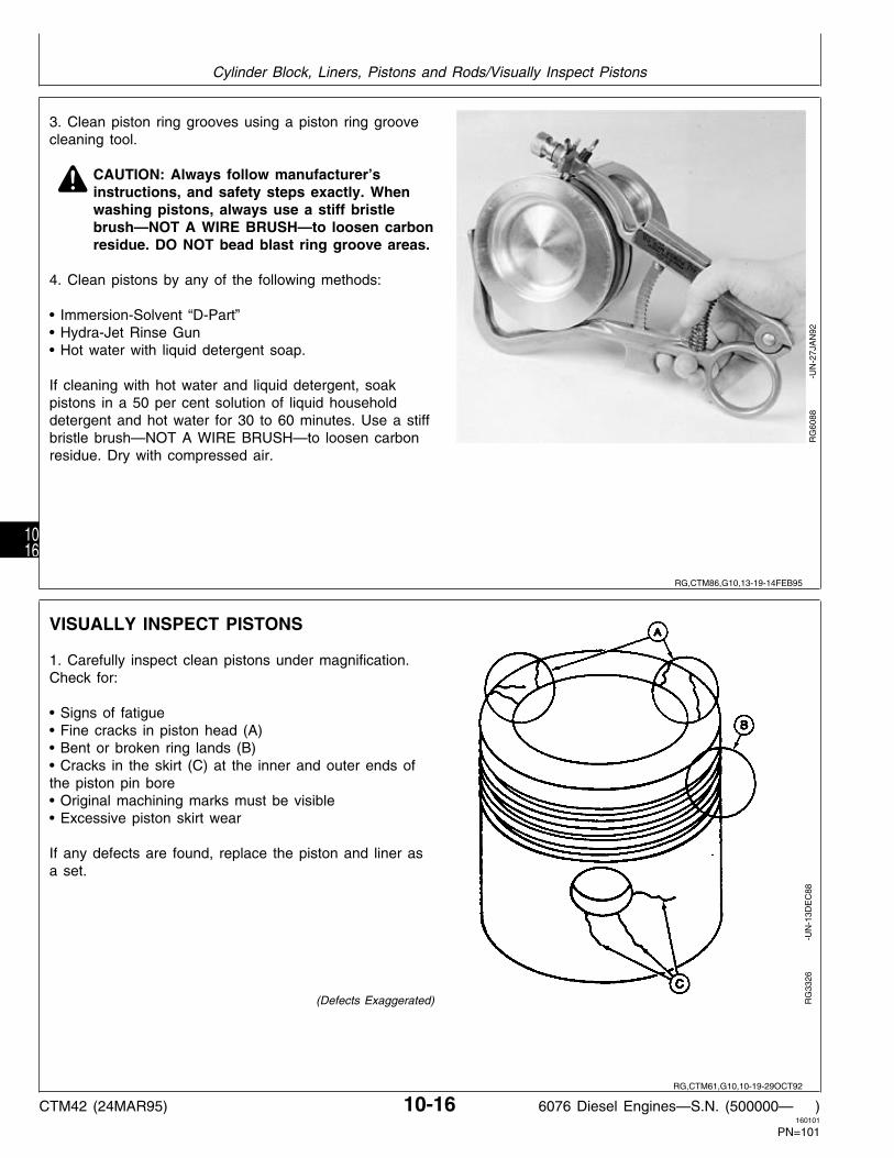
3. Clean piston ring grooves using a piston ring groovecleaning tool.
N CAUTION: Always follow manufacturer’sinstructions, and safety steps exactly. Whenwashing pistons, always use a stiff bristlebrush—NOT A WIRE BRUSH—to loosen carbonresidue. DO NOT bead blast ring groove areas.
4. Clean pistons by any of the following methods:
• Immersion-Solvent “D-Part”• Hydra-Jet Rinse Gun• Hot water with liquid detergent soap.
If cleaning with hot water and liquid detergent, soakpistons in a 50 per cent solution of liquid householddetergent and hot water for 30 to 60 minutes. Use a stiffbristle brush—NOT A WIRE BRUSH—to loosen carbonresidue. Dry with compressed air.
RG
6088
-U
N-2
7JA
N92
VISUALLY INSPECT PISTONS
1. Carefully inspect clean pistons under magnification.Check for:
• Signs of fatigue• Fine cracks in piston head (A)• Bent or broken ring lands (B)• Cracks in the skirt (C) at the inner and outer ends ofthe piston pin bore• Original machining marks must be visible• Excessive piston skirt wear
If any defects are found, replace the piston and liner asa set.
(Defects Exaggerated) RG
3326
-U
N-1
3DE
C88
RG,CTM86,G10,13-19-14FEB95
RG,CTM61,G10,10-19-29OCT92
Cylinder Block, Liners, Pistons and Rods/Visually Inspect Pistons
CTM42 (24MAR95) 10-16 6076 Diesel Engines—S.N. (500000— )160101
PN=101
1016

CHECK PISTON COMPRESSION RINGGROOVE WEAR
1. Use the JDE55 Ring Groove Wear Gauge to checkwear of keystone ring grooves. Check each groove atseveral locations.
RG
5230
-U
N-1
3DE
C88
Gauge shoulders should not contact ring land (D) ofpiston. If ring grooves are worn, replace piston and lineras a set. If ring grooves are good, proceed to next step.
A—Piston with Worn Ring GrooveB—Keystone Ring GrooveC—JDE55 Ring Groove Wear GaugeD—Ring LandE—Gauge ShoulderF—Piston with Good Ring Groove
R24
201
-UN
-13D
EC
88
RG,CTM42,G10,32-19-14FEB95
S11,2010,DG -19-17FEB87
Cylinder Block, Liners, Pistons and Rods/Check Piston Ring Groove Wear
CTM42 (24MAR95) 10-17 6076 Diesel Engines—S.N. (500000— )160101
PN=102
1017

MEASURE OIL CONTROL RING GROOVE
1. Check oil control ring-to-groove clearance by installinga new ring in groove.
2. Measure clearance with a feeler gauge at severalpoints. Compare measurements with specifications givenbelow.
OIL CONTROL RING-TO-GROOVE CLEARANCE SPECIFICATIONS
New Part Clearance . . . . . . . . . . . . . . . . . . . . . 0.064—0.102 mm(0.0025—0.0040 in.)
Maximum Serviceable Clearance . . . . . . . . . . . . . . . . . . 0.165 mm(0.0065 in.)
NOTE: Replace piston and liner (as a set) if oil controlring clearance exceeds specifications given.
RG
5234
-U
N-1
3DE
C88
INSTALL PISTON PIN IN PISTON PIN BORE
NOTE: Piston pin must be in good condition and notworn beyond specification given below.
1. Dip piston pin in clean engine oil.
2. Install pin (A) through piston.
Pin should pass through piston using only light thumbpressure. Check taper in piston pin bore by inserting pinfrom both sides. If pin enters freely, but binds in thecenter, the bore could be tapered (B). If bore is nottapered, insert pin to check for bore alignment. Pinshould not “click” or need to be forced into bore onopposite side (C).
3. Check piston pin and piston bore specifications. Ifeither are not within specification, replace pin, piston,and liner.
PISTON PIN/BORE SPECIFICATIONS
Piston Pin OD . . . . . . . . . . . . . . . . . . . . . . . . . 47.60—47.61 mm(1.8739—1.8745 in.)
Piston Pin Bore ID . . . . . . . . . . . . . . . . . . . . . . 47.62—47.63 mm(1.8748—1.8752 in.)
RG
5231
-U
N-1
3DE
C88
RG
4984
-U
N-2
6JU
L94
S11,2010,JF -19-29OCT92
RG,CTM42,G10,33-19-14FEB95
Cylinder Block, Liners, Pistons and Rods/Install Piston Pin in Piston Pin Bore
CTM42 (24MAR95) 10-18 6076 Diesel Engines—S.N. (500000— )160101
PN=103
1018

VISUALLY INSPECT CYLINDER LINERS
IMPORTANT: If pitting has occurred, check conditionof coolant.
1. Inspect exterior length of liner for pitting (A). Checkpacking step for erosion (B). If pitting or erosion isobserved, measure the depth of pits and erosion with afine wire or needle.
Replace piston and liner if:
—Pitting depth is one-half liner thickness (C) or more.
—Erosion depth is one-half packing step (D) or more.
CYLINDER LINER SPECIFICATIONS
Cylinder Liner Thickness . . . . . . . . . . . . . . . . . . 6.05—6.15 mm(0.238—0.242 in.)
Packing Step Dimension . . . . . . . . . . . . . . . . . . 1.45—1.55 mm(0.057—0.061 in.)
NOTE: Liners are reusable if the depth of pits or erosionis less than one-half the amount specified. Wheninstalling these liners, rotate 90˚ from originalposition. The liners should be deglazed and ringsets installed on pistons.
A—Liner PittingB—Liner ErosionC—Liner ThicknessD—Packing Step
RG
4643
-U
N-1
3DE
C88
2. Visually examine liner ID. Replace piston and liner if:
— The crosshatch honing pattern is not visibleimmediately below the top ring turn-around area.
— Liners are pitted or contain deep vertical scratchesthat can be detected by the fingernail.
3. Carefully examine liner for signs of fatigue, such asfine cracks in the flange area (A) and cracks in the ringtravel area (B).
NOTE: Inspect block for cracks or erosion in the O-ringpacking areas. See INSPECT AND CLEANCYLINDER BLOCK, later in this group.
(Exaggerated defects)
RG
1188
-U
N-1
3DE
C88
RG,CTM42,G10,34-19-22JUL94
RG,CTM61,G10,14-19-22JUL94
Cylinder Block, Liners, Pistons and Rods/Visually Inspect Cylinder Liners
CTM42 (24MAR95) 10-19 6076 Diesel Engines—S.N. (500000— )160101
PN=104
1019

CYLINDER LINER MANUFACTURING DATE CODE EXPLANATION
A manufacturing four-digit date code will appear onthe liner. The following is an example of this four-digitdate code:
HL90H . . . . . . . . . . . . . . . . . . . . . . . . . . . . . . Liner Material Type L . . . . . . . . . . . . . . . . . . . . . Month Liner was Manufactured 90 . . . . . . . . . . . . . . . . . . . . Year Liner was Manufactured
Liner Material SpecificationH . . . . . . . . . . . . . . . . . . . . . . . . . . . . . . . . . Hardened Bore
Month Liner was ManufacturedA . . . . . . . . . . . . . . . . . . . . . . . . . . . . . . . . . . . . . . JanuaryB . . . . . . . . . . . . . . . . . . . . . . . . . . . . . . . . . . . . . . FebruaryC . . . . . . . . . . . . . . . . . . . . . . . . . . . . . . . . . . . . . . . MarchD . . . . . . . . . . . . . . . . . . . . . . . . . . . . . . . . . . . . . . . . . AprilE . . . . . . . . . . . . . . . . . . . . . . . . . . . . . . . . . . . . . . . . . MayF . . . . . . . . . . . . . . . . . . . . . . . . . . . . . . . . . . . . . . . . JuneG . . . . . . . . . . . . . . . . . . . . . . . . . . . . . . . . . . . . . . . . . JulyH . . . . . . . . . . . . . . . . . . . . . . . . . . . . . . . . . . . . . . . AugustI . . . . . . . . . . . . . . . . . . . . . . . . . . . . . . . . . . . . . SeptemberJ . . . . . . . . . . . . . . . . . . . . . . . . . . . . . . . . . . . . . . . OctoberK . . . . . . . . . . . . . . . . . . . . . . . . . . . . . . . . . . . . . NovemberL . . . . . . . . . . . . . . . . . . . . . . . . . . . . . . . . . . . . . December
Year Liner Was Manufactured90 . . . . . . . . . . . . . . . . . . . . . . . . . . . . . . . . . . . . . . . . 199091 . . . . . . . . . . . . . . . . . . . . . . . . . . . . . . . . . . . . . . . . 1991 etc.
When installing new liners, the liner manufacturingdate code should be toward the front of the engine.This will help with future repairs in knowing whetherthe liners have been moved or not during a previousrepair.
RG
5944
-U
N-3
0AU
G91
RG,CTM42,G10,11-19-08MAR94
Cylinder Block, Liners, Pistons and Rods/Cylinder Liner Manufacturing Date Code Explanation
CTM42 (24MAR95) 10-20 6076 Diesel Engines—S.N. (500000— )160101
PN=105
1020

MEASURE PISTON SKIRT OD
1. Measure piston skirt diameter (B) at right angles topiston pin bore (C) 19.1 mm (0.75 in.) from the bottomof the piston (A).
2. Measure cylinder liner as directed later in this groupand compare with piston measurement.
PISTON SKIRT DIAMETER SPECIFICATION
Piston OD: 19.1 mm (0.75 in.) from Bottom of Skirt . . . . . . . . . . . . . . . . . . 115.771—115.789 mm
(4.5579—4.5586 in.)
RG
5232
-U
N-1
3DE
C88
3. Place piston (without rings) in matched liner.
4. Compare liner ID measurement with piston skirt ODmeasurement to determine piston-to-liner clearance (A).Piston-to-liner clearance specifications are:
PISTON-TO-LINER CLEARANCE
New Part . . . . . . . . . . . . . . . . . . . . . . . . . . . 0.076—0.124 mm(0.0030—0.0049 in.)
Maximum Wear Tolerance . . . . . . . . . . . . . . . . . . . . . 0.152 mm(0.0060 in.)
Replace piston and liner as a matched set if clearanceexceeds limit.
NOTE: Pistons and liners require replacement if linertaper or out-of-roundness (top-to-bottom in ringtravel area) is more than 0.051 mm (0.0020 in).See MEASURE CYLINDER LINERS, later in thisgroup.
RG
5233
-U
N-1
3DE
C88
RG,CTM42,G10,35-19-17MAR95
RG,CTM42,G10,36-19-17MAR95
Cylinder Block, Liners, Pistons and Rods/Measure Piston Skirt OD
CTM42 (24MAR95) 10-21 6076 Diesel Engines—S.N. (500000— )160101
PN=106
1021

MEASURE CYLINDER LINER ID
IMPORTANT: ALWAYS measure liners at roomtemperature.
A—Measure liner bore parallel to piston pin at top end ofring travel.
B—Measure bore in same position at bottom end of ringtravel.
C—Measure bore at right angle to piston pin at top endof ring travel.
D—Measure bore in same position at bottom end of ringtravel.
Compare measurements A, B, C, and D to determine ifliner is tapered or out-of-round.
Compare liner ID with piston OD.
CYLINDER LINER SPECIFICATIONS
Maximum Wear or Taper in Ring Travel Area . . . . . . . . . . . . . . . . . . . . . . . . . . . . 0.051 mm
(0.002 in)
Maximum Liner Out-of-Round . . . . . . . . . . . . . . . . . . . . . 0.051 mm(0.002 in.)
Maximum Piston-to-Liner Clearance . . . . . . . . . . . . . . . . . . 0.15 mm(0.006 in.)
NOTE: Replace piston and liner (as a set) if they exceedwear specifications given.
R25
922
-UN
-13D
EC
88
MEASURE CYLINDER LINER FLANGETHICKNESS
Measure cylinder liner flange thickness at severallocations. If liner flange is not within specifications,replace piston and liner set.
LINER FLANGE SPECIFICATIONS
Flange Thickness . . . . . . . . . . . 8.175—8.225 mm (0.322—0.324 in.)
RG
4727
-U
N-1
3DE
C88
S11,2010,JQ -19-14FEB95
S11,2510,AV -19-16AUG94
Cylinder Block, Liners, Pistons and Rods/Measure Liner Flange Thickness
CTM42 (24MAR95) 10-22 6076 Diesel Engines—S.N. (500000— )160101
PN=107
1022
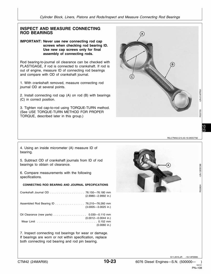
INSPECT AND MEASURE CONNECTINGROD BEARINGS
IMPORTANT: Never use new connecting rod capscrews when checking rod bearing ID.Use new cap screws only for finalassembly of connecting rods.
Rod bearing-to-journal oil clearance can be checked withPLASTIGAGE, if rod is connected to crankshaft. If rod isout of engine, measure ID of connecting rod bearingsand compare with OD of crankshaft journal.
1. With crankshaft removed, measure connecting rodjournal OD at several points.
2. Install connecting rod cap (A) on rod (B) with bearings(C) in correct position.
3. Tighten rod cap-to-rod using TORQUE-TURN method.(See USE TORQUE-TURN METHOD FOR PROPERTORQUE, described later in this group.) R
G57
05
-
UN
-01A
PR
91
4. Using an inside micrometer (A) measure ID ofbearing.
5. Subtract OD of crankshaft journals from ID of rodbearings to obtain oil clearance.
6. Compare measurements with the followingspecifications.
CONNECTING ROD BEARING AND JOURNAL SPECIFICATIONS
Crankshaft Journal OD . . . . . . . . . . . . . . . . . . . 76.150—76.180 mm(2.9980—2.9992 in.)
Assembled Rod Bearing ID . . . . . . . . . . . . . . . . 76.210—76.260 mm(3.0005—3.0025 in.)
Oil Clearance (new parts) . . . . . . . . . . . . . . . . . . 0.030—0.110 mm(0.0012—0.0044 in.)
Wear Limit . . . . . . . . . . . . . . . . . . . . . . . . . . . . . . . . . 0.152 mm(0.0060 in.)
7. Inspect connecting rod bearings for wear or damage.If bearings are worn or not within specification, replaceboth connecting rod bearing and rod pin bearing.
RG
3824
-U
N-1
3DE
C88
RG,CTM42,G10,40-19-29OCT92
S11,2010,JR -19-14FEB95
Cylinder Block, Liners, Pistons and Rods/Inspect and Measure Connecting Rod Bearings
CTM42 (24MAR95) 10-23 6076 Diesel Engines—S.N. (500000— )160101
PN=108
1023

INSPECT CONNECTING ROD AND CAP
1. Inspect rod and cap for wear or damage, such aschips or cracks in the area of the tongue-and-groovejoints (A).
2. Inspect in and around cap screw holes (B) in cap. Ifany defects are found, replace rod and cap.
RG
3749
-U
N-1
3DE
C88
3. Carefully clamp rod in a soft-jawed vise (cap endupward).
4. Install cap WITHOUT bearing inserts.
IMPORTANT: Never use new connecting rod capscrews when checking rod bore ID. Usenew cap screws only for final assemblyof connecting rods.
5. Initially tighten blind hole cap screw to 27 N·m (20lb-ft), then tighten open hole cap screw to same torque.
6. Tighten cap screws to 75 N·m (55 lb-ft), then tighteneach cap screw an additional 90˚—100˚. (SeeTORQUE-TURN CONNECTING ROD CAP SCREWS,later in this group.)
RG
4982
-U
N-1
3DE
C88
S11,0402,AE -19-08MAR94
S11,2010,JS -19-14FEB95
Cylinder Block, Liners, Pistons and Rods/Inspect Rod and Cap
CTM42 (24MAR95) 10-24 6076 Diesel Engines—S.N. (500000— )160101
PN=109
1024

6. Using an inside micrometer, measure rod bore atcenter of bore and record measurements as follows:
A. At right angle to rod/cap joint.B. At 45˚ left of measurement “A”.C. At 45˚ right of measurement “A”.
ROD BORE SPECIFICATIONS
Rod Bore ID . . . . . . . . . . . . . . . . . . . . . . . . . . 81.051—81.077 mm(3.191—3.192 in.)
7. Compare the measurements. If difference between thegreatest and least measurement is more than 0.04 mm(0.0016 in.), the rod and cap are out-of-round. Replaceboth connecting rod and cap.
8. Remove cap screw (D). Using a feeler gauge,measure gap at rod/cap joint (E). If gap is excessive,mating surfaces of rod and cap are worn and must bereplaced.
ROD CAP SPECIFICATIONMaximum End Gap . . . . . . . . . . . . . . . . . . . . . 0.25 mm (0.010 in.)
RG
6661
-U
N-1
1MA
R93
9. Measure connecting rod pin bore-to-crankshaft borecenter-to-center dimension (A) and compare withspecification given. If measurement is not withinspecification, replace rod.
CENTERLINE OF PISTON BORE-TO-CRANKSHAFT BORE
New part . . . . . . . . . . . . . . 222.20—222.30 mm (8.748—8.752 in.)
RG
6455
-U
N-2
2OC
T92
S11,2010,JU -19-12APR93
RG,CTM42,G10,37-19-16AUG94
Cylinder Block, Liners, Pistons and Rods/Inspect Rod and Cap
CTM42 (24MAR95) 10-25 6076 Diesel Engines—S.N. (500000— )160101
PN=110
1025

INSPECT PISTON PINS AND BUSHINGS
1. Insert piston pin (A) through piston pin bushing andcarefully clamp in a soft-jawed vise.
2. Rotate connecting rod (B) back and forth severaltimes to make sure connecting rod moves freely onpiston pin.
3. Remove piston pin from vise and connecting rod.
RG
3172
-U
N-1
3DE
C88
4. Insert pin from either side of rod bushing. If pin is freeon one end, but tight on the other, the bore could betapered (A). If pin enters freely from both sides, but istight in the center, bore is bellmouthed (B).
5. Measure ID of rod pin bushing and OD of piston pin.Compare measurements with specifications given below:
PISTON PIN BORE SPECIFICATIONS
OD of Piston Pin . . . . . . . . . . . . . . . . . . . . . . . 47.597—47.613 mm(1.8739—1.8745 in.)
ID of Pin Bore in Piston . . . . . . . . . . . . . . . . . . 47.620—47.630 mm(1.8748—1.8752 in.)
ID of Installed Rod Pin Bushing(After Boring) . . . . . . . . . . . . . . . . . . . . . . . . . 47.655—47.681 mm
(1.8762—1.8772 in.)
Rod Pin-to-Bushing Oil Clearance . . . . . . . . . . . . 0.042—0.084 mm(0.0017—0.0033 in.)
Maximum Serviceable . . . . . . . . . . . . . . . . . . . . . . . . . 0.102 mm(0.0040 in.)
6. If necessary, remove and replace piston pin bushing.See REMOVE PISTON PIN BUSHING, CLEAN ANDINSPECT PIN BORE, later in this group.
RG
4983
-U
N-1
3DE
C88
S11,2010,DM -19-08MAR94
S11,2010,JG -19-14SEP94
Cylinder Block, Liners, Pistons and Rods/Inspect Piston Pins and Bushings
CTM42 (24MAR95) 10-26 6076 Diesel Engines—S.N. (500000— )160101
PN=111
1026

REMOVE PISTON PIN BUSHING
IMPORTANT: Do not use any power tool to removeor install piston pin bushing.
1. If necessary, remove pin bushing with the JDG337Connecting Rod Bushing Service Set.
Use the following tools from the service set:
A—JDG339 CupB—JDG338 AdapterC—JDE98-4 DriverD—STD36104 Forcing Screw with Washer
IMPORTANT: Use care to properly align the JDE98-4Driver with bushing so that theconnecting rod bushing bore is notdamaged.
RG
4985
-U
N-1
3DE
C88
CLEAN AND INSPECT CONNECTING RODPIN BORE
1. Clean rod bushing bore using a medium grit emerycloth, as burrs will distort bushing. Install bushing onopposite side of rod burr.
2. If necessary, file a slight chamfer (A) around bore toremove any sharp edges. Chamfer will also aid inbushing installation.
3. Measure rod pin bore in three places approximately45˚ apart. Compare the measurements with thespecifications given below:
CONNECTING ROD PIN BORE SPECIFICATIONS(Bushing Removed)
ID of Rod Pin Bore . . . . . . . . . . . . . . . . . . . . . 52.354—52.380 mm(2.0612—2.0622 in.)
IMPORTANT: If connecting rod pin bore diameter isnot within specification or bushing hasspun in rod, discard rod and replacewith a new one.
RG
5227
-U
N-1
3DE
C88
S11,2010,J1 -19-12APR93
S11,2010,JJ -19-12APR93
Cylinder Block, Liners, Pistons and Rods/Clean and Inspect Piston Pin Bushing Bore in Rod
CTM42 (24MAR95) 10-27 6076 Diesel Engines—S.N. (500000— )160101
PN=112
1027

INSTALL PISTON PIN BUSHING IN ROD
1. Lubricate rod bushing bore and bushing with cleanengine oil. Install bushing using the JDG337 andJDE98A Connecting Rod Bushing Service Sets.
Use the following tools from the above sets andassemble in sequence as shown:
A—STD36104 Forcing Screw With WasherB—JDE98A DriverC—JDG338 AdapterD—Service BushingE—JDE98-3 PilotF—JDE339 Cup
IMPORTANT: Be sure oil hole in service bushing andconnecting rod are properly aligned.
Boring the piston pin bushing shouldbe done ONLY by experiencedpersonnel on equipment capable ofmaintaining bushing specification.
2. Precision bore and hone bushing to the specifieddimensions.
CONNECTING ROD PIN BORE AND BUSHING SPECIFICATIONS
Rod Pin Bore-to-Bushing Press FitSpecification . . . . . . . . . . . . . . . . . . . . . . . . . . . 0.084—0.147 mm
(0.0033—0.0058 in.)ID of Installed Service Rod PinBushing (Before Honing) . . . . . . . . . . . . . . . . . . 47.579—7.628 mm
(1.8732—1.8751 in.)
ID of Installed Rod Pin Bushing(After Honing) . . . . . . . . . . . . . . . . . . . . . . . . . 47.655—47.681 mm
(1.8762—1.8772 in.)Bearing Bore-to-Pin Bushing Bore (Center-to-Center) Length . . . . . . . . . . . . 222.20—222.30 mm
(8.748—8.752 in.)
3. Check piston pin-to-rod pin bushing clearance. SeeINSPECT PISTON PINS AND BUSHINGS, earlier in thisgroup. Replace piston pin as required.
RG
4986
-U
N-1
3DE
C88
S11,2010,JK -19-16AUG94
Cylinder Block, Liners, Pistons and Rods/Install Piston Pin Bushing in Connecting Rod
CTM42 (24MAR95) 10-28 6076 Diesel Engines—S.N. (500000— )160101
PN=113
1028

COMPLETE DISASSEMBLY OF CYLINDER BLOCK (IF REQUIRED)
If complete inspection and “Hot Tank” cleaning ofcylinder block is required, refer to the appropriategroup for removal of all external and internal mountedcomponents listed below:
1. Remove crankshaft and pulley if not previouslyremoved. (Group 15)
2. Remove all remaining lubrication systemcomponents. (Group 20) Remove starting motor.
3. Remove water pump and all remaining coolingsystem components. (Group 25)
4. Remove timing gear train and camshaft. (Group16)
5. Remove fuel injection pump and fuel filterassembly. (Group 35)
6. If necessary to “Hot Tank” the block, remove oilgallery plugs, water gallery plugs, piston coolingorifices and the engine serial number plate. (SeeREMOVE AND CLEAN PISTON COOLINGORIFICES, later in this group.)
REMOVE AND CLEAN PISTON COOLINGORIFICES
1. Remove all six piston cooling orifices (A) and inspecteach cooling orifice to make sure it is not plugged ordamaged.
2. Use a soft wire and compressed air to clean orifice.Replace, if condition is questionable.
IMPORTANT: A piston cooling orifice failure couldcause damage to pistons, piston pins,rod pin bushings, and liners. If a pistoncooling orifice is left out, low or no oilpressure will result.
RG
5811
-U
N-1
2AU
G91
RG,CTM42,G10,6 -19-22JUL94
RG,CTM42,G10,7 -19-29OCT92
Cylinder Block, Liners, Pistons and Rods/Remove and Clean Piston Cooling Orifices
CTM42 (24MAR95) 10-29 6076 Diesel Engines—S.N. (500000— )160101
PN=114
1029

INSPECT AND CLEAN CYLINDER BLOCK
NOTE: All components (including piston cooling orifices),water gallery plugs and oil gallery plugs must beremoved from the cylinder block for inspectionand cleaning. Refer to the proper group forremoval of all external and internal mountedcomponents.
1. Clean block thoroughly using cleaning solvent,pressure steam, or a hot tank.
IMPORTANT: If cylinder block is cleaned in a hottank, be sure to remove any aluminumparts. Aluminum parts can be damagedor destroyed by hot tank solutions.Remove all serial number plates.
RG,CTM42,G10,38-19-29OCT92
Cylinder Block, Liners, Pistons and Rods/Inspect and Clean Cylinder Block
CTM42 (24MAR95) 10-30 6076 Diesel Engines—S.N. (500000— )160101
PN=115
1030

2. Be sure liner support flange (A) is free of any burrs. Ifburrs are present, use a small half-moon file andLIGHTLY file (in a circular motion) burr off atapproximately a 60˚ angle. DO NOT let file hit top ofcylinder block while filing.
NOTE: DO NOT file liner support flange excessively.Excess filing can damage liner support flangeand allow an improper liner fitting. Thoroughlyclean all filings from cylinder block (B).
3. Carefully inspect block for cracks or damage. If acracked block is suspected, pressure-test the block. Aprocedure for pressure testing is outlined in FOS(Fundamentals of Service) Manual-ENGINES. Replacecracked or damaged block.
COUNTERBORE DEPTH AND LINER FLANGE SPECIFICATIONS
Cylinder Liner Counterbore Depth . . . . . . . . . . . . 8.105—8.155 mm(0.319—0.321 in.)
Liner Flange Thickness . . . . . . . . . . . . . . . . . . . 8.175—8.225 mm(0.322—0.324 in.)
4. When determined that the cylinder block isserviceable, remove cylinder head locating dowels. Cleanout all threaded holes for cylinder head cap screws intop deck of cylinder block. Use JDG681A Tap or anequivalent 9/16-12 UNC-2A tap approximately 114.3 mm(4.5 in.) long. Use compressed air to remove any debrisor fluid which may be present in the cap screw hole.
5. Install new locating dowel pins in cylinder block.
RG
3329
-U
N-1
3DE
C88
RG
5796
-U
N-1
2AU
G91
RG,CTM42,G10,8 -19-17MAR95
Cylinder Block, Liners, Pistons and Rods/Inspect and Clean Cylinder Block
CTM42 (24MAR95) 10-31 6076 Diesel Engines—S.N. (500000— )160101
PN=116
1031
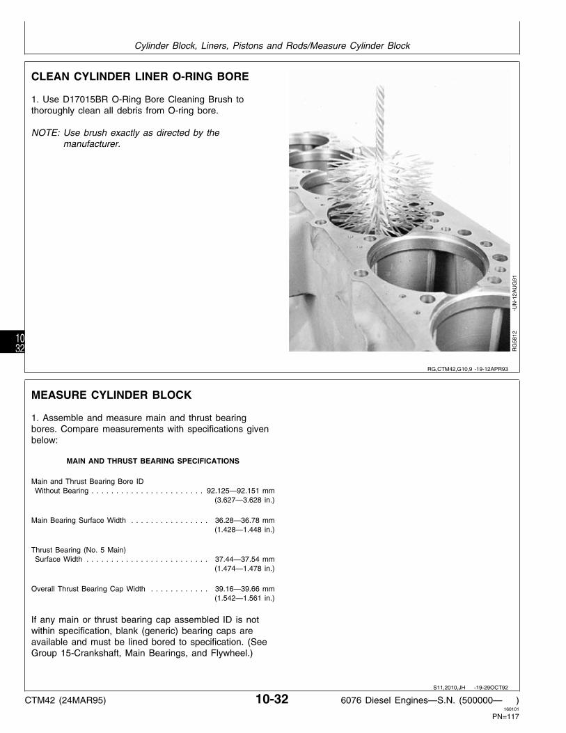
CLEAN CYLINDER LINER O-RING BORE
1. Use D17015BR O-Ring Bore Cleaning Brush tothoroughly clean all debris from O-ring bore.
NOTE: Use brush exactly as directed by themanufacturer.
RG
5812
-U
N-1
2AU
G91
MEASURE CYLINDER BLOCK
1. Assemble and measure main and thrust bearingbores. Compare measurements with specifications givenbelow:
MAIN AND THRUST BEARING SPECIFICATIONS
Main and Thrust Bearing Bore ID Without Bearing . . . . . . . . . . . . . . . . . . . . . . . 92.125—92.151 mm
(3.627—3.628 in.)
Main Bearing Surface Width . . . . . . . . . . . . . . . . 36.28—36.78 mm(1.428—1.448 in.)
Thrust Bearing (No. 5 Main) Surface Width . . . . . . . . . . . . . . . . . . . . . . . . . 37.44—37.54 mm
(1.474—1.478 in.)
Overall Thrust Bearing Cap Width . . . . . . . . . . . . 39.16—39.66 mm(1.542—1.561 in.)
If any main or thrust bearing cap assembled ID is notwithin specification, blank (generic) bearing caps areavailable and must be lined bored to specification. (SeeGroup 15-Crankshaft, Main Bearings, and Flywheel.)
RG,CTM42,G10,9 -19-12APR93
S11,2010,JH -19-29OCT92
Cylinder Block, Liners, Pistons and Rods/Measure Cylinder Block
CTM42 (24MAR95) 10-32 6076 Diesel Engines—S.N. (500000— )160101
PN=117
1032

2. Measure cam follower bore diameter at all borelocations. Record measurements by bore location.
CAMSHAFT FOLLOWER AND BORE SPECIFICATIONS
Cam Follower Bore ID . . . . . . . . . . . . . . . . . . . 17.384—17.440 mm(0.6845—0.6865 in.)
Cam Follower OD . . . . . . . . . . . . . . . . . . . . . . . 17.33—17.35 mm(0.682—0.683 in.)
Maximum Cam Follower-to-Bore Clearance . . . . . . . . . . . . . . . . . . . . . . . . . . . . . . . . . . 0.114 mm
(0.0045 in.)
If any one cam follower bore is not within specification,install a new cylinder block.
3. Measure camshaft bore diameter at all locations andrecord readings. Compare measurements withspecifications given in chart below:
CAMSHAFT BUSHING AND BORE SPECIFICATION
Camshaft Bushing Installed ID . . . . . . . . . . . . . 67.076—67.102 mm(2.6408—2.6418 in.)
Camshaft Bushing Bore in Block . . . . . . . . . . . . 69.987—70.013 mm(2.7554—2.7564 in.)
Maximum Runout of Camshaft Bushing Bore in Block . . . . . . . . . . . . . . . . . . . . . . . . . . . . . . 0.038 mm
(0.0015 in.)New Camshaft Bushing-to-Journal Clearance . . . . . . . . . . . . . . . . . . . . . . . . . . . 0.063—0.115 mm
(0.0025—0.0045 in.)
If camshaft bushing bore diameter in block is more thanspecified, install a new cylinder block. R
G58
30
-
UN
-12A
UG
91
S11,2010,JV -19-12APR93
RG,CTM42,G10,22-19-14FEB95
Cylinder Block, Liners, Pistons and Rods/Measure Cylinder Block
CTM42 (24MAR95) 10-33 6076 Diesel Engines—S.N. (500000— )160101
PN=118
1033

4. Measure cylinder block top deck flatness usingD05012ST Precision Straightedge and feeler gauge.Resurface as required.
CYLINDER BLOCK TOP DECK SPECIFICATIONS
Maximum Out-of-Flat (Over Entire Length or Width) . . . . . . . . . . . . . . . . . . . . . 0.10 mm
(0.004 in.)
Straightness per Any 305 mm (12 in.) Length . . . . . . . . . . . . . . . . . . . . . . 0.025 mm (0.001 in.)
Minimum Main Bearing Bore Centerline-to- Top Deck Distance . . . . . . . . . . . . . . . . . . . . . . . . . . 352.35 mm
(13.872 in.)
IMPORTANT: The centerline of the main bearingbore-to-top deck of cylinder blockMUST be 352.35—352.50 mm(13.872—13.878 in.). If not, replacecylinder block.
INSTALL PISTON COOLING ORIFICES ANDGALLERY PLUGS
IMPORTANT: A piston cooling orifice failure couldcause damage to pistons, piston pins,rod pin bushings, and liners. If a pistoncooling orifice is left out, low or no oilpressure will result.
1. Install all six piston cooling orifices (A) and tighten to11 N·m (97 lb-in.).
2. Install new oil and water gallery plugs as required, ifremoved.
RG
5811
-U
N-1
2AU
G91
S11,2010,JW -19-16AUG94
RG,CTM42,G10,10-19-29OCT92
Cylinder Block, Liners, Pistons and Rods/Install Piston Cooling Orifices and Gallery Plugs
CTM42 (24MAR95) 10-34 6076 Diesel Engines—S.N. (500000— )160101
PN=119
1034

RECHECK CYLINDER LINER STANDOUT(HEIGHT ABOVE BLOCK)
NOTE: If a new liner assembly is being installed in anew or used cylinder block, liner height must bechecked.
Be sure liner bore in cylinder block and top deck ofblock are clean.
1. Install liners without O-ring. Secure with cap screwsand washers and measure liner standout. SeeMEASURE CYLINDER LINER STANDOUT (HEIGHTABOVE BLOCK), earlier in this group.
Liner shims may be used to bring to bring standoutwithin specification. (See INSTALL LINER SHIMS—IFREQUIRED, later in this group.)
RG,CTM42,G10,23-19-22JUL94
Cylinder Block, Liners, Pistons and Rods/Recheck Cylinder Liner Standout (Height above Block)
CTM42 (24MAR95) 10-35 6076 Diesel Engines—S.N. (500000— )160101
PN=120
1035

INSTALL LINER SHIMS—IF REQUIRED
If the liner flange thickness is within specification, butrecorded standout was no more than 0.08 mm (0.003in.) BELOW top deck of block, install liner shims onbottom of liner flange.
The liner shim is 0.05 mm (0.002 in.) thick. A maximumof two liner shims may be used per cylinder, as required.Shims have tangs in the I.D. to help hold them in placeagainst bottom of liner flange during liner installation.
1. Make sure counterbore in block is clean and free ofburrs. Install liner(s), and shim(s), in block bore withoutO-rings. Secure liners with cap screws and washers asdone previously. Tighten cap screws to 68 N·m (50 lb-ft).
Liner standout MUST NOT exceed 0.102 mm (0.004 in.)after shim installation.
2. Measure liner standout again at 1, 5, 7, and 11O’clock positions. Record measurements.
If standout is still not within specification, remove linerand determine cause.
If standout is within specification, proceed to next step.
RG,CTM6,G10,2 -19-08MAR94
Cylinder Block, Liners, Pistons and Rods/Install Liner Shims—If Required
CTM42 (24MAR95) 10-36 6076 Diesel Engines—S.N. (500000— )160101
PN=121
1036

INSTALL CYLINDER LINER O-RINGS ANDPACKINGS
IMPORTANT: DO NOT use oil on cylinder linerpacking or O-rings. Oil can cause thered packing to swell, which squeezesliner and could possibly cause ascored piston.
1. Pour AR54749 Soap Lubricant into a suitablecontainer.
2. Dip new packings and O-rings in soap beforeinstallation. Do not leave packings or O-rings in soap tosoak.
3. Install the black viton O-ring (A) in the lower O-ringgroove of the cylinder block (C).
4. Install the red silicone O-ring (B) in the upper O-ringgroove of the cylinder block.
RG
3826
-U
N-1
3DE
C88
5. Turn cylinder liner (B) upside-down and install thesquare neoprene packing (A) over outside of liner.
6. Slide packing down firmly against second shoulder ofthe liner.
NOTE: Make sure the square packing is not twisted.
7. Coat the liner packings sealing area of the cylinderliner and cylinder block O-rings with liquid soap.
RG
3827
-U
N-1
3DE
C88
S11,0402,BA -19-16AUG94
S11,2010,JT -19-29OCT92
Cylinder Block, Liners, Pistons and Rods/Install Cylinder Liner O-Rings and Packings
CTM42 (24MAR95) 10-37 6076 Diesel Engines—S.N. (500000— )160101
PN=122
1037

INSTALL CYLINDER LINERS
IMPORTANT: Install cylinder liners into same cylinderblock bore as removed.
DO NOT scuff liner packing acrossupper counterbore.
Pitted or eroded liners that meet reuseguidelines should be rotated 90˚ fromtheir removed position. See VISUALLYINSPECT CYLINDER LINERS, earlier inthis group for reuse guidelines.
1. Install liner and packing in block bore with marktoward front of engine, unless liner OD is pitted oreroded.
If liner OD is pitted or eroded, but still within acceptableservice limits, rotate liner 90˚ from it’s removed position.Pitted sections of the liner should be facing the front orrear of engine.
2. A resistance will be felt when cylinder liner is alignedin pilot bore.
3. Using only the pressure of both palms, the cylinderliner should drop to a point nearly flush with the upperflange of the cylinder liner and cylinder block.
RG
5814
-U
N-1
2AU
G91
RG,CTM42,G10,12-19-12APR93
Cylinder Block, Liners, Pistons and Rods/Install Cylinder Liners
CTM42 (24MAR95) 10-38 6076 Diesel Engines—S.N. (500000— )160101
PN=123
1038

4. Finish seating cylinder liners using a clean, hardwoodblock and hammer.
5. Gently tap hardwood block over top of cylinder linerwith mallet.
NOTE: Cylinder liner will protrude over top of cylinderblock more than normal due to uncompressedpackings and O-rings.
IMPORTANT: If you suspect that a packing may havesheared or displaced liner installation,remove liner and packing assembly. Ifno damage is found, check packingand O-rings for proper position.Re-soap packings and reinstall linerassembly.
6. Hold liners in place with large flat washers and capscrews. Turn cap screws snug but do not tighten.
7. Clean cylinder liner bores with waterless hand cleanerafter installation. Wipe dry with clean towels.
8. Apply clean engine oil to liner bores immediately toprevent corrosion.
RG
5815
-U
N-1
2AU
G91
RG,CTM42,G10,13-19-14FEB95
Cylinder Block, Liners, Pistons and Rods/Install Cylinder Liners
CTM42 (24MAR95) 10-39 6076 Diesel Engines—S.N. (500000— )160101
PN=124
1039

INSTALL PISTONS AND CONNECTINGRODS
IMPORTANT: Pistons must be installed on sameconnecting rod from which they wereremoved.
If a new piston and liner assembly is tobe installed, DO NOT remove pistonfrom liner. Push piston out of linerbottom only far enough to install pistonpin.
1. Use the JDE93 Ring Expander to install piston rings(F) and oil control ring with expander ring (E).
NOTE: New rings are furnished with the correct end gap,therefore, fitting to the liner is not usuallynecessary.
A—Piston Pin“Pip” marks on No. 1 and No. 2 compressionB—Piston
rings must face top of piston. C—Connecting RodD—Snap Rings (2 used)
2. Lubricate piston pin (A) and bushing with clean engine E—Oil Control Ring with Expander RingF—Piston Ringsoil.
3. Install piston pin through piston (B) and connectingrod (C). Be sure front of rod aligns with front of piston.
4. Install NEW piston pin snap rings (D) in grooves.Make certain snap rings have expanded in grooves ofpiston.
PISTON COMPRESSION RING END GAP SPECIFICATIONS
Pistons Stamped RE50868: No. 1 . . . . . . . . . . . . . . . . . . . . . . . . . . . . . . . . 0.43—0.69 mm
(0.017—0.027 in.) No. 2 . . . . . . . . . . . . . . . . . . . . . . . . . . . . . . . . 0.63—0.89 mm
(0.025—0.035 in.)Pistons Stamped RE57512: No. 1 . . . . . . . . . . . . . . . . . . . . . . . . . . . . . . . . 0.43—0.69 mm
(0.017—0.027 in.) No. 2 . . . . . . . . . . . . . . . . . . . . . . . . . . . . . . . . 1.27—1.52 mm
(0.050—0.060 in.)
RG
5239
-U
N-1
3DE
C88
S11,2010,JO -19-16AUG94
Cylinder Block, Liners, Pistons and Rods/Install Pistons and Connecting Rods
CTM42 (24MAR95) 10-40 6076 Diesel Engines—S.N. (500000— )160101
PN=125
1040

5. Stagger ring gap on pistons as shown.
NOTE: If crankshaft was removed, see INSTALLCRANKSHAFT in Group 15.
6. Coat pistons, liners and ID of JDE96 Piston RingCompressor with clean engine oil.
A—Top of PistonB—Top Compression Ring GapC—Oil Control Ring GapD—Expander Ring GapE—Bottom Compression Ring GapF—Front of Engine
R31
127
-UN
-13D
EC
88
7. Carefully place ring compressor with piston and rodover liner.
IMPORTANT: Be sure crankshaft journals and linerwalls are not damaged when installingpiston and rod in liner.
NOTE: Be sure the word “FRONT” on piston and rodface toward the front of the engine.
8. With piston centered in ring compressor and ringsstaggered correctly, push piston into liner.
RG
5816
-U
N-1
2AU
G91
S11,2010,JW1 -19-07AUG91
RG,CTM42,G10,14-19-02NOV92
Cylinder Block, Liners, Pistons and Rods/Install Pistons and Connecting Rods
CTM42 (24MAR95) 10-41 6076 Diesel Engines—S.N. (500000— )160101
PN=126
1041

9. Apply clean engine oil to bearing inserts (B) andcrankshaft rod journals (A).
IMPORTANT: NEVER use connecting rod cap screwsmore than once for final engineassembly. Once rod cap screws havebeen tightened, they cannot be reusedfor final asssembly.
10. Install connecting rod caps.
RG
5817
-U
N-1
2AU
G91
11. Dip NEW cap screws and washers in clean engineoil. Make sure top of cap screws have oil on them also.
IMPORTANT: Using pneumatic wrenches to installcap screws may cause damage to thethreads.
12. Initially tighten cap screw (A) to 27 N·m (20 lb-ft)before tightening the other cap screw.
13. Secondly, tighten all cap screws to 75 N·m (55 lb-ft).
14. Finally TORQUE-TURN all cap screws 90—100˚.(See USE TORQUE-TURN METHOD FOR PROPERTORQUE, described next in this group.)
RG
5818
-U
N-1
2AU
G91
RG,CTM42,G10,15-19-12APR93
RG,CTM42,G10,16-19-29OCT92
Cylinder Block, Liners, Pistons and Rods/Install Pistons and Connecting Rods
CTM42 (24MAR95) 10-42 6076 Diesel Engines—S.N. (500000— )160101
PN=127
1042

TORQUE-TURN CONNECTING ROD CAPSCREWS
• Using engine axis method to TORQUE-TURNconnecting rod cap screws:
1. After tightening cap screws to 75 N·m (55 lb-ft), markconnecting rod cap and socket.
2. Position handle of wrench parallel to centerline ofengine crankshaft axis (A).
3. Tighten 1/4 turn (90—100˚) clockwise until handle ofwrench is perpendicular to centerline of enginecrankshaft axis (B) as shown.
RG
7047
-U
N-2
8JU
L94
• Using JT05993 Torque Angle Gauge toTORQUE-TURN connecting rod cap screws:
1. After tightening cap screws to 75 N·m (55 lb-ft), followdirections provided with gauge and TORQUE-TURN eachcap screw 90˚—100˚.
JT05993 Torque Angle Gauge RG
5698
-U
N-2
7AU
G90
CHECK ENGINE ROTATION FOREXCESSIVE TIGHTNESS
1. Rotate crankshaft several revolutions to be sureengine rotates without excessive tightness.
2. Check liners for deep scratches caused by animproperly installed or broken piston ring.
3. Check side clearance of rods. Must have slightside-to-side movement.
RG,CTM86,G10,41-19-14FEB95
RG,CTM6,G10,4 -19-22AUG91
S11,0402,BK -19-08MAR94
Cylinder Block, Liners, Pistons and Rods/Check Engine Rotation for Excessive Tightness
CTM42 (24MAR95) 10-43 6076 Diesel Engines—S.N. (500000— )160101
PN=128
1043

COMPLETE FINAL ASSEMBLY
NOTE: Refer to the proper group for installation ofcomponents.
1. Install camshaft and timing gear cover. (Group 16)
2. Install oiling system components. (Group 20)
3. Install cylinder head with new head gasket. Installvalve train. (Group 05)
4. Install fuel injection system components. (Group35)
5. Install water bypass pipe. (Group 25)
6. Install crankshaft pulley. (Group 15)
7. Install alternator, fan, and fan belts. (MachineTechnical Manual)
8. Install exhaust manifold and intake assembly.(Group 30)
9. Install starting motor, if removed.
10. Fill engine with clean oil and proper coolant.(Group 02)
11. Perform engine break-in. (Group 05)
RG,CTM42,G10,17-19-14FEB95
Cylinder Block, Liners, Pistons and Rods/Complete Final Assembly
CTM42 (24MAR95) 10-44 6076 Diesel Engines—S.N. (500000— )160101
PN=129
1044

SPECIAL OR ESSENTIAL TOOLS
NOTE: Order tools according to information given in theU.S. SERVICE-GARD™ Catalog or in theEuropean Microfiche Tool Catalog (MTC).
Dial Indicator . . . . . . . . . . . . . (English, in.) D17526CIor (Metric, mm ) D17527CI
Use with JDG451 to measure valve recess and cylinderliner height-to-cylinder block top deck.
RG
6246
-U
N-2
7MA
R92
Front Wear Sleeve Installer . . . . . . . . . . . . . . . JDE3
Install front oil seal in timing gear cover.
RG5080 -UN-23AUG88
Gear Driver . . . . . . . . . . . . . . . . . . . . . . . . . . JDH7
Install crankshaft drive gear.
RG5108 -UN-23AUG88
Flywheel Turning Tool . . . . . . . . . . . . . . . . . JDG820
Used to rotate engine to check damper radial runout andtime engine. JDE81-1 may be used also if JDG820 isnot available.
RG
7056
-U
N-1
0AU
G94
DX,TOOLS -19-05JUN91
RG,D17526CI -19-29OCT92
S53,JDE3A -19-16AUG94
S53,JDH7 -19-04AUG94
RG,JDG820 -19-14FEB95
Group 15Crankshaft, Main Bearings and Flywheel
CTM42 (24MAR95) 15-1 6076 Diesel Engines—S.N. (500000— )160101
PN=130
151

Piston and Liner Height Gauge . . . . . . . . . . . JDG451
Measure piston and liner heights.
NOTE: A dial indicator is not supplied with JDG451. UseD17526CI (English, in.) or D17527CI (Metric,mm) Dial Indicator with JDG451.
RG
7029
-U
N-3
0SE
P94
Seal and Wear Sleeve Installer . . . . . . . . JDG476(85)
Used to simultaneously install the new teflon unitized oilseal and wear sleeve on the rear crankshaft flange. Usewith JDG796 Alignment Tool to install rear oil sealhousing eliminating need for dial indicator to measurerunout.
Consists of: JDG477(85) Pilot JDG478 Driver
RG
5106
-U
N-2
3AU
G88
Seal Puller Adapter . . . . . . . . . . . . . . . . . . . JDG719
Used with a standard metal screw, JDE38-2 Shank, andJDE38-3 Slide Handle to remove front crankshaft oil sealwith timing gear cover installed. Also used to removerear crankshaft oil seal with seal housing installed.
Set consists of: 1—Adapter . . . . . . . . . . . . . . . . . . . . . . JDG719-1 2—Screw (not shown) . . . . . . . . . . . . . . . . 11200
RG
6214
-U
N-0
6MA
R92
Seal Installer . . . . . . . . . . . . . . . . . . . . . . . JDG720
Used to install front crankshaft oil seal with timinggear cover installed.
Set consists of: 1—Forcing Screw . . . . . . . . . . . . . . . . . JDG720-1 2—Seal Protector . . . . . . . . . . . . . . . . . JDG720-2 3—Seal Installer . . . . . . . . . . . . . . . . . . JDG720-3 4—Ring (500 Series Engines) . . . . . . . . . JDG720-4
RG
6215
-U
N-0
6MA
R92
RG,JDG451 -19-28SEP94
S11,2515,BW -19-03MAY93
RG,JDG719 -19-29OCT92
RG,JDG720 -19-01APR93
Crankshaft, Main Bearings and Flywheel/Special or Essential Tools
CTM42 (24MAR95) 15-2 6076 Diesel Engines—S.N. (500000— )160101
PN=131
152

Hub Puller Kit . . . . . . . . . . . . . . . . . . . . . . JDG721
Used with JDG787 Thread Protector to remove vibrationdamper pulley assembly on some engine applications.
RG
5763
-U
N-0
6AU
G91
Front Wear Sleeve Puller . . . . . . . . . . . . . . . JDG786
Used to remove front crankshaft wear sleeve with timinggear cover installed.
RG
6428
-U
N-1
3OC
T92
Thread Protector . . . . . . . . . . . . . . . . . . . . . JDG787
Used with any puller set to remove vibration damperpulley assembly.
RG
6429
-U
N-1
3OC
T92
RG,JDG721 -19-03MAY93
RG,JDG786 -19-29OCT92
RG,JDG787 -19-03FEB93
Crankshaft, Main Bearings and Flywheel/Special or Essential Tools
CTM42 (24MAR95) 15-3 6076 Diesel Engines—S.N. (500000— )160101
PN=132
153

Rear Wear Sleeve Puller Kit . . . . . . . . . . . . . JDG790
Used to remove rear wear sleeve with oil seal housinginstalled on 400, 450, and 500 Series Engines.
Set consists of:
A—Hose Clamp (500 Series) . . . . . . . . . . . . . 219469B—Collet Halves (400/450 Series) . . . . . . . . JDG790-1C—Forcing Screw (400/450/500 Series) . . . . . . 35945D—Pulling Plate (400/450/500 Series) . . . . . JDG790-2E—Retainer Clip (400/450/500 Series) . . . . . . . 13876F—Shaft Protector (400/450/500 Series) . . . . . . 215177G—Collet Halves (500 Series) . . . . . . . . . . JDG790-3H—Hose Clamp (400/450 Series) . . . . . . . . . . 19311
RG
6457
-U
N-2
2OC
T92
Oil Seal Housing Alignment Tool . . . . . . . . . . JDG796
Use with oil seal housing casting numbers R115050 andR125027.
RG6590 -UN-18FEB93
SERVICE EQUIPMENT AND TOOLS
NOTE: Order tools from the U.S. SERVICEGARD™ Catalog or from the European Microfiche Tool Catalog(MTC). Some tools may be available from a local supplier.
Name Use
D01251AA Puller* Used to remove crankshaft gear.
*Part of D01047AA 17-1/2 and 30-Ton Puller Set
RG,JDG790 -19-03OCT94
RG,JDG796 -19-08AUG94
RG,CTM42,G15,32-19-11JUN93
Crankshaft, Main Bearings and Flywheel/Service Equipment and Tools
CTM42 (24MAR95) 15-4 6076 Diesel Engines—S.N. (500000— )160101
PN=133
154

OTHER MATERIAL
Name Use
LOCTITE 242 (TY9370) Coat threads of flywheel mounting cap screws.Thread Lock and Sealer
LOCTITE 515 (TY6304) Flexible Coat trimmed flywheel housing-to-cylinder blockSealant (General Purpose) gasket.
LOCTITE 609 (TY15969) Retaining Compound Coat OD of crankshaft flange for installation of rearoil seal/wear sleeve.
PLASTIGAGE Check main bearing-to-crankshaft journal oil clearanceduring engine disassembly.
Brake Kleen or Ignition Cleaner and Drier Remove sealant from crankshaft flange.
S11,2015,EE -19-11OCT94
Crankshaft, Main Bearings and Flywheel/Other Material
CTM42 (24MAR95) 15-5 6076 Diesel Engines—S.N. (500000— )160101
PN=134
155

CRANKSHAFT, MAIN BEARINGS, AND FLYWHEEL SPECIFICATIONS
ITEM SPECIFICATION WEAR LIMIT
Crankshaft Fillet Radius: Pin Journal . . . . . . . . . . . . . . . . . . . . 3.94—4.44 mm (0.156—0.175 in.) —— Thrust Journal . . . . . . . . . . . . . . . . . . 3.56—4.06 mm (0.140—0.160 in.) —— Main Journal . . . . . . . . . . . . . . . . . . . 3.94—4.44 mm (0.156—0.175 in.) ——
Engine Stroke . . . . . . . . . . . . . . . . . . . . 121 mm (4.75 in.)
Crankshaft End Play . . . . . . . . . . . . . . . 0.038—0.380 mm (0.0015—0.0150 in.) ——
Main Bearing Journal OD . . . . . . . . . . . . 85.65—85.67 mm (3.372—3.373 in.) ——
Main Bearing Assembled ID . . . . . . . . . . 85.705—85.755 mm (3.3742—3.3762 in.) ——
Main Bearing-to-Journal Clearance . . . . . . 0.030—0.108 mm (0.0012—0.0042 in.) ——
Connecting Rod Journal OD . . . . . . . . . . 76.15—76.18 mm (2.9980—2.9990 in.) ——
Crankshaft Rear Oil Seal- to-Housing Maximum Runout . . . . . . . . 0.152 mm (0.0060 in.) ——
Journal Taper per 25.4 mm (1.00 in.) Length . . . . . . . . . . . . . . . . . 0.0025 mm (0.0001 in.) ——
Journal Out-of-Roundness . . . . . . . . . . . . 0.025 mm (0.0010 in.) ——
Undersized Bearings Available . . . . . . . . . 0.05, 0.25, 0.51 and 0.76 mm(0.002, 0.010, 0.020, and 0.030 in.) ——
Oversize Thrust Washer Available . . . . . . 0.18 mm (0.007 in.) ——
Main Bearing Cap Bore Specifications: ID without Bearing Inserts . . . . . . . . . . 92.125—92.151 mm (3.6270—3.6280 in.) —— Maximum Bore Diameter Taper . . . . . . . 0.008 mm (0.0003 in.) —— Maximum Bore Diameter Variation . . . . . 0.013 mm (0.0005 in.) —— Maximum Straightness Variation (Any Bore-to-Adjacent Bores) . . . . . . . 0.038 mm (0.0015 in.) —— Maximum Straightness Variation (5 Center Bores-to-End Bores) . . . . . . 0.076 mm (0.0030 in.) —— Centerline of Bore-to-Top Deck of Block . . . . . . . . . . . . . . . . . 352.35—352.50 mm (13.872—13.878 in.) ——
Main Bearing Cap Surface Width . . . . . . . 36.28—36.78 mm (1.428—1.448 in.) ——
RG,CTM42,G15,37-19-14FEB95
Crankshaft, Main Bearings and Flywheel/Crankshaft, Main Bearings, and Flywheel Specifications
CTM42 (24MAR95) 15-6 6076 Diesel Engines—S.N. (500000— )160101
PN=135
156

CRANKSHAFT, MAIN BEARINGS, AND FLYWHEEL SPECIFICATIONS—CONTINUED
ITEM SPECIFICATION WEAR LIMIT
No. 5 Main (Thrust) Bearing: Surface Width (Thrust Washer Clearance) . . . . . 37.44—37.54 mm (1.474—1.478 in.) —— Overall Cap Width . . . . . . . . . . . . 39.16—39.66 mm (1.542—1.561 in.) —— Base Circle OD for Thrust Washer Clearance* . . . . . . . . . . 123.70—125.30 mm (4.87—4.93 in.) ——
Crankshaft OD for Front Pulley . . . . . 47.650—47.676 mm (1.8785—1.876 in.) ——
Front Pulley ID . . . . . . . . . . . . . . . 47.594—47.630 mm (1.8738—1.8752 in.) ——
Damper Pulley Radial Runout (Maximum) . . . . . . . 1.02 mm (0.040 in.) ——
Front Oil Seal Housing Install Below Front of Timing Gear Cover (Maximum) . . . 8.4 mm (0.33 in.) ——
Oil Pump Drive Gear-to-Crankshaft Clearance . . . . . . . . . . . . . . . . . 0.38 mm (0.015 in.) ——
Maximum Rear Oil Seal Housing Runout . . . . . . . . . . . . . 0.15 mm (0.006 in.) ——
Flywheel Housing Face Runout Maximum Variation . . . . . . . . . . . 0.20 mm (0.008 in.) ——
Flywheel Face Flatness Maximum Variation . . . . . . . . . . . 0.23 mm (0.009 in.) —— Maximum Variation per 25 mm (1.0 in.) of travel . . . . . . 0.013 mm (0.0005 in.) ——
Flywheel Bearing Bore Concentricity Maximum Variation . . . . . . . . . . . 0.127 mm (0.005 in.) ——
* Thrust (washer) surfaces on bearing cap must be flat in respect tomating thrust (washer) surfaces in cylinder block. RG,CTM42,G15,1 -19-14FEB95
Crankshaft, Main Bearings and Flywheel/Crankshaft, Main Bearings, and Flywheel Specifications
CTM42 (24MAR95) 15-7 6076 Diesel Engines—S.N. (500000— )160101
PN=136
157

CRANKSHAFT, MAIN BEARINGS, AND FLYWHEEL SPECIFICATIONS—CONTINUED
TORQUES
Flywheel Housing-to-Cylinder Block . . . . . . . . . . . . . . . . . . . . . . . . . . . . . . . . . . . . . . . 407 N·m (300 lb-ft)Damper Pulley-to-Crankshaft . . . . . . . . . . . . . . . . . . . . . . . . . . . . . . . . . . . . . . . . . . . . 230 N·m (170 lb-ft)Main Bearing Caps . . . . . . . . . . . . . . . . . . . . . . . . . . . . . . . . . . . . . . . . . . . . . . . . . . 203 N·m (150 lb-ft)Rear Crankshaft Oil Seal Housing . . . . . . . . . . . . . . . . . . . . . . . . . . . . . . . . . . . . . . . . . 27 N·m (20 lb-ft)Flywheel-to-Crankshaft . . . . . . . . . . . . . . . . . . . . . . . . . . . . . . . . . . . . . . . . . . . . . . . . 115 N·m (85 lb-ft)Piston Cooling Orifices . . . . . . . . . . . . . . . . . . . . . . . . . . . . . . . . . . . . . . . . . . . . . . . . . . 11 N·m (8 lb-ft)Damper Assembly-to-Pulley . . . . . . . . . . . . . . . . . . . . . . . . . . . . . . . . . . . . . . . . . . . . . 41 N·m (30 lb-ft)Injection Pump Gear Cover-to-Timing Gear Cover . . . . . . . . . . . . . . . . . . . . . . . . . . . . . . 27 N·m (20 lb-ft)Timing Gear Cover-to-Cylinder Block* . . . . . . . . . . . . . . . . . . . . . . . . . . . . . . . . . . . . . . . 27 N·m (20 lb-ft)Hub Drive-to-Flywheel . . . . . . . . . . . . . . . . . . . . . . . . . . . . . . . . . . . . . . . . . . . . . . . . 115 N·m (85 lb-ft)Magnetic Pickup-to-Timing Gear Cover . . . . . . . . . . . . . . . . . . . . . . . . . . . . . . . . . . . . . . 14 N·m (10 lb-ft)
* See INSTALL TIMING GEAR COVER—NON-AUXILIARY DRIVEENGINES, later in this group, for proper cap screw tighteningsequence.
CRANKSHAFT AND MAIN BEARING FAILURE ANALYSIS
• Scored Main Bearing:(Diagnosis also applies to connecting rod bearing.)
Oil starvation.Contaminated oil.Engine parts failure.Excessive heat.Poor periodic service.
• Galled or “Wiped” Bearings:
Fuel in lubricating oil (incomplete combustion).Coolant in lubrication system (cracked block, liner seal failure, or leaking water pump seal with plugged hole).Insufficient bearing oil clearance.Parts not lubricated prior to engine operation.Wrong bearing size.
• Inconsistent Wear Pattern:
Misaligned or bent connecting rod.Warped or bowed crankshaft.Distorted cylinder block.
• Broken Main Bearing Caps:
Improper installation.Dirt between bearing and crankshaft journal.Low oil pressure.Oil pump failure.
• Cracked, Chipped or Broken Bearings:
Overspeeding.Excessive idling.Lugging.Excessive oil clearance.Improper installation.
RG,CTM42,G15,47-19-24MAR95
S11,2015,C -19-29SEP94
Crankshaft, Main Bearings and Flywheel/Failure Analysis
CTM42 (24MAR95) 15-8 6076 Diesel Engines—S.N. (500000— )160101
PN=137
158
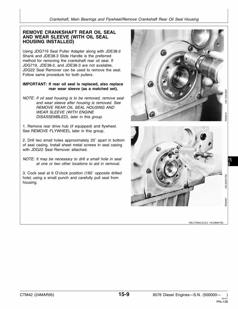
REMOVE CRANKSHAFT REAR OIL SEALAND WEAR SLEEVE (WITH OIL SEALHOUSING INSTALLED)
Using JDG719 Seal Puller Adapter along with JDE38-2Shank and JDE38-3 Slide Handle is the preferredmethod for removing the crankshaft rear oil seal. IfJDG719, JDE38-2, and JDE38-3 are not available,JDG22 Seal Remover can be used to remove the seal.Follow same procedure for both pullers.
IMPORTANT: If rear oil seal is replaced, also replacerear wear sleeve (as a matched set).
NOTE: If oil seal housing is to be removed, remove sealand wear sleeve after housing is removed. SeeREMOVE REAR OIL SEAL HOUSING ANDWEAR SLEEVE (WITH ENGINEDISASSEMBLED), later in this group.
1. Remove rear drive hub (if equipped) and flywheel.See REMOVE FLYWHEEL later in this group.
2. Drill two small holes approximately 20˚ apart in bottomof seal casing. Install sheet metal screws in seal casingwith JDG22 Seal Remover attached.
NOTE: It may be necessary to drill a small hole in sealat one or two other locations to aid in removal.
3. Cock seal at 6 O’clock position (180˚ opposite drilledhole) using a small punch and carefully pull seal fromhousing.
RG
5819
-U
N-1
2AU
G91
RG
6467
-U
N-2
6OC
T92
RG,CTM42,G15,2 -19-03MAY93
Crankshaft, Main Bearings and Flywheel/Remove Crankshaft Rear Oil Seal Housing
CTM42 (24MAR95) 15-9 6076 Diesel Engines—S.N. (500000— )160101
PN=138
159

4. Assemble JDG790 Rear Wear Sleeve Puller andposition onto crankshaft flange with wear sleeve seatedin jaws.
5. Securely tighten band clamp in groove on OD of jaws.
6. Tighten forcing screw with disc centered in crankshaftflange until wear sleeve is removed from crankshaft.
RG
6468
-U
N-2
6OC
T92
Clean OD of crankshaft flange with cleaning solvent,acetone, or any other suitable cleaner that will removesealant. (Brake Kleen, Ignition Cleaner and Drier areexamples of commercially available solvents that willremove sealant from flange.)
Look for nicks or burrs on wear ring surface and bore inflywheel housing. If necessary, use a polishing cloth.
Finish cleaning by wiping flange with a clean rag. Anysmall nicks should be removed with 180-grit or finerpolishing cloth.
Check oil seal housing runout as explained later in thisgroup.
RG
5822
-U
N-1
2AU
G91
RG,CTM42,G15,50-19-29OCT92
RG,CTM42,G15,4 -19-29OCT92
Crankshaft, Main Bearings and Flywheel/Remove Crankshaft Rear Oil Seal Housing
CTM42 (24MAR95) 15-10 6076 Diesel Engines—S.N. (500000— )160101
PN=139
1510

INSTALL CRANKSHAFT REAR OIL SEALAND WEAR SLEEVE (WITHOUT ENGINEDISASSEMBLY)
NOTE: These instructions are for use when the oil sealhousing and oil pan would not be removed. Referto INSTALL CRANKSHAFT REAR OIL SEALAND WEAR SLEEVE (WITH ENGINEDISASSEMBLED), later in this group, forinstructions with oil seal housing and oil panremoved.
1. Apply a light coating of LOCTITE 609 RetainingCompound, or equivalent, completely around the leadingedge of crankshaft flange. Wipe away any sealant thatmay have gotten on ID of seal housing bore.
2. Install JDG477 (85) Pilot (A) on end of crankshaftusing the Allen head cap screws (B) supplied with toolset. Tighten cap screws securely.
IMPORTANT: Handle seal and wear sleeve assemblycarefully. If assembly becomesseparated, discard these parts andinstall a new assembly. (SeeCRANKSHAFT REAR OIL SEAL ANDWEAR SLEEVE HANDLINGPRECAUTIONS, later in this group.)
3. Carefully start oil seal/wear sleeve assembly (C) overJDG477 (85) Pilot and crankshaft flange with open sideof seal toward engine.
IMPORTANT: When installing the JDG478 Driver onJDG477 (85) Pilot and crankshaft flangeto position oil seal/wear sleeveassembly, locate crossbar of installer atright angle (90˚) to Allen head capscrews. This allows the crossbar tobottom on pilot, not head of capscrews, assuring correct installation.
RG
4639
-U
N-1
4DE
C88
S11,2015,GQ -19-16AUG94
Crankshaft, Main Bearings and Flywheel/Install Crankshaft Rear Oil Seal and Wear Sleeve
CTM42 (24MAR95) 15-11 6076 Diesel Engines—S.N. (500000— )160101
PN=140
1511

4. Position JDG478 Driver (A) so that hole in the crossplate goes over threaded stud of pilot. Install washer andnut on stud.
5. Tighten nut to draw JDG478 Driver in until crossbarbottoms on JDG477(85) Pilot. When the tool bottoms,seal and wear ring assembly (B) will be correctlypositioned.
6. Remove JDG476(85) Tool Set from engine.
RG
4640
-U
N-1
4DE
C88
INSPECT VIBRATION DAMPER
IMPORTANT: Do not immerse the vibration damperor the damper pulley in cleaningsolvent. Doing so may damage therubber portions of these components.
Never apply thrust on outer ring ofdamper. Damper is sensitive to impactdamage, such as being dropped orstruck with a hammer.
The damper assembly is not repairableand should be replaced every 5 yearsor 4500 hours, whichever occurs first,or whenever crankshaft is replaced.
1. Remove fan belts (shown removed).
2. Inspect damper for torn or split rubber protruding fromdamper, ring shift toward front or back of damper, orslippage of the ring (reference chisel marks). Replacedamper if any defects are found.
3. Grasp vibration damper (A) with both hands andattempt to turn it in both directions. If rotation is felt,damper is defective and should be replaced.
RG
5823
-U
N-0
5SE
P91
S11,2015,GR -19-11JUN93
RG,CTM42,G15,5 -19-16AUG94
Crankshaft, Main Bearings and Flywheel/Inspect Vibration Damper
CTM42 (24MAR95) 15-12 6076 Diesel Engines—S.N. (500000— )160101
PN=141
1512

4. Check vibration damper radial runout by positioning adial indicator (A) so probe (B) contacts damper O.D.
5. Rotate crankshaft using JDE81-1 Flywheel TurningTool.
6. Note dial indicator reading.
DAMPER RADIAL RUNOUT SPECIFICATION
Maximum . . . . . . . . . . . . . . . . . . . . . . . . . . . . 1.02 mm (0.040 in.)
If runout exceeds specifications, replace vibrationdamper.
RG
5824
-U
N-1
2AU
G91
CHECK CRANKSHAFT END PLAY
1. Completely engage then release the clutch lever.
2. Place a dial indicator on damper face.
IMPORTANT: Use care not to damage or distort thetiming gear cover or bearing insertswhen prying. Do not pry on outerinteria ring of damper.
3. Pry with flat bar between the damper pulley andtiming gear cover.
CRANKSHAFT END PLAY SPECIFICATIONS
End Play . . . . . . . . . . . . . . . . . . . . . . . . . . . . . 0.038—0.380 mm(0.0015—0.0150 in.)
NOTE: New thrust bearings will usually restore properend play.
RG
5934
-U
N-2
8AU
G91
RG,CTM42,G15,6 -19-16AUG94
RG,CTM42,G105,8-19-29OCT92
Crankshaft, Main Bearings and Flywheel/Check Crankshaft End Play
CTM42 (24MAR95) 15-13 6076 Diesel Engines—S.N. (500000— )160101
PN=142
1513

REMOVE DAMPER PULLEY
1. Drain oil (if not previously done), and remove oil pan.Remove oil pump if crankshaft is to be removed.
2. Remove cap screw (B) and washer on damper pulley(A).
RG
5827
-U
N-1
2AU
G91
RG,CTM42,G15,7 -19-29OCT92
Crankshaft, Main Bearings and Flywheel/Remove Damper Pulley
CTM42 (24MAR95) 15-14 6076 Diesel Engines—S.N. (500000— )160101
PN=143
1514

IMPORTANT: DO NOT use a jaw-type puller toremove vibration damper. Damagecould result to the damper. Never applythrust on outer ring of damper. Do notdrop or hammer on damper.
NOTE: On some applications, it may be necessary toremove the pulley from the damper before pullingdamper from crankshaft flange.
3. Remove pulley and damper from crankshaft usingD01207AA(OTC518) Puller Set (upper photo).
On certain applications, it may be necessary to useJDG721 Hub Puller (B) and JDG787 Thread Protector(A) (lower photos) to remove damper pulley.
RG
5765
-U
N-0
6AU
G91
RG
6469
-U
N-2
6OC
T92
RG
6470
-U
N-2
6OC
T92
RG,CTM42,G15,33-19-16AUG94
Crankshaft, Main Bearings and Flywheel/Remove Damper Pulley
CTM42 (24MAR95) 15-15 6076 Diesel Engines—S.N. (500000— )160101
PN=144
1515

REMOVE CRANKSHAFT FRONT OIL SEAL(WITH TIMING GEAR COVER INSTALLED ONENGINE)
IMPORTANT: Whenever front oil seal is replaced, thewear sleeve must also be replaced.
NOTE: If timing gear cover is going to be removed fromengine, remove front seal after timing gear coveris removed.
1. Check oil seal and wear sleeve for wear, damage, orleakage.
2. Center punch seal casing at 12 O’clock position.
RG
6471
-U
N-2
6OC
T92
3. Drill 1/8 in. hole in casing.
RG
6472
-U
N-2
6OC
T92
4. Using JDG719 Seal Puller along with JDE38-2 Shank,JDE38-3 Hammer, and metal screw; remove seal.
5. Remove keyway from keyslot of crankshaft.R
G64
73
-
UN
-26O
CT
92
RG,CTM42,G15,38-19-03MAY93
RG,CTM42,G15,39-19-29OCT92
RG,CTM42,G15,40-19-29OCT92
Crankshaft, Main Bearings and Flywheel/Remove Front Oil Seal
CTM42 (24MAR95) 15-16 6076 Diesel Engines—S.N. (500000— )160101
PN=145
1516

REMOVE CRANKSHAFT FRONT WEARSLEEVE (WITH TIMING GEAR COVERINSTALLED OR REMOVED)
1. Position JDG786 Front Wear Sleeve Puller oncrankshaft nose.
2. Center puller on wear sleeve and thread onto sleeveapproximately two full turns.
3. Tighten forcing screw until wear sleeve is removedfrom crankshaft flange.
NOTE: To remove wear sleeve from tool, place tool invise and cut two slots adjacent from each otherin wear sleeve using hack saw or parting wheel.Put file or similar flat object in slots and turnwear sleeve out of tool.
4. Clean crankshaft flange using Brake Kleen or IgnitionCleaner and Drier.
RG
6474
-U
N-2
6OC
T92
RG
6475
-U
N-2
6OC
T92
INSTALL CRANKSHAFT FRONT WEARSLEEVE
NOTE: Wear sleeve can also be installed with timinggear cover removed, but seal must be installedwith timing gear cover installed.
1. Coat ID of new wear sleeve with LOCTITE 609Retaining Compound.
2. Using JDG467 Driver from JDE3 Installer along withwasher and 5/8-11 UNC x 3 in. cap screw that securesdamper pulley assembly to crankshaft. Tighten cap screwuntil driver bottoms.
3. Remove installation tools and clean any sealant fromOD of wear sleeve or ID of seal bore.
RG
6476
-U
N-2
6OC
T92
RG
6477
-U
N-2
6OC
T92
RG,CTM42,G15,41-19-03MAY93
RG,CTM42,G15,42-19-11JUN93
Crankshaft, Main Bearings and Flywheel/Install Front Wear Sleeve
CTM42 (24MAR95) 15-17 6076 Diesel Engines—S.N. (500000— )160101
PN=146
1517

INSTALL CRANKSHAFT FRONT OIL SEAL(WITH TIMING GEAR COVER INSTALLED ONENGINE)
IMPORTANT: Whenever front oil seal is replaced, thewear sleeve MUST be replaced also.
1. Place JDG720-2 Seal Protector (A) on nose ofcrankshaft. Lubricate ID of front oil seal lips with cleanengine oil. Slide seal with spring side of seal facingengine onto seal protector. Be careful not to roll oil seallips.
2. Place JDG720-3 Seal Installer onto seal protectoragainst seal. Do not use spacer ring provided with toolset.
3. With nut and washer installed onto JDG720-1 ForcingScrew, thread forcing screw into nose of crankshaft untilit bottoms.
4. Tighten nut against crossplate of installer until installerbottoms onto front face of timing gear cover.
5. Remove installation tools. Verify seal is installedsquare in bore and that seal lips are not rolled on wearsleeve.
Oil seal should be 8.4 mm (0.33 in.) below front lip ofseal bore.
RG
6479
-U
N-2
6OC
T92
RG
6480
-U
N-2
6OC
T92
RG,CTM42,G15,43-19-03MAY93
Crankshaft, Main Bearings and Flywheel/Install Front Oil Seal
CTM42 (24MAR95) 15-18 6076 Diesel Engines—S.N. (500000— )160101
PN=147
1518

REPLACE TIMING GEAR COVER (6076HRW33, 34, AND 35 ENGINES) —ENGINEINSTALLED IN VEHICLE
6076HRW33, 34, and 35 Engines used in 8100,8200, and 8300 Tractors are equipped with frontframe/oil sump, refer to TM1575 (8100, 8200, 8300,and 8400 Tractors—Repair) for access to frontframe/oil sump-to-engine block cap screws.
To Remove Timing Gear Cover:
1. Remove viscous fan drive, drive housing, andcoupler. (Refer to TM1575.)
2. Remove crankshaft vibration damper as detailedearlier in this group.
3. Disconnect water piping and remove water pumpcover with water bypass tube. Remove and discardgaskets.
4. Back out all front frame/oil sump-to-engine blockcap screws 9.5 mm (0.38 in.)
5. Disconnect engine speed sensor connector fromsensor.
6. Remove injection pump drive gear cover.
7. Slowly lift engine block assembly approximately 6.4mm (0.25 in.) using safety approved lifting equipment.
IMPORTANT: The timing gear cover must not be“dragged” horizontally while incontact with front frame/oil sumpgasket. Doing so may damagegasket sealing bead.
8. Remove remaining cap screws and carefullyremove timing gear cover. Remove and discard timinggear cover gasket.
9. Remove front oil seal from timing gear cover anddiscard seal.
10. Remove front wear sleeve from crankshaft flangeand discard sleeve.
To Install Timing Gear Cover:
1. Thoroughly clean all timing gear cover gasketsurfaces and front oil seal bore.
NOTE: Front wear sleeve can be installed with timinggear cover removed or installed.
2. Install a new front wear sleeve on crankshaftflange (See INSTALL FRONT WEAR SLEEVE, laterin this group).
3. Install timing gear cover (See INSTALL TIMINGGEAR COVER, later in this group).
4. Install Front oil seal (See INSTALL CRANKSHAFTFRONT OIL SEAL WITH TIMING GEAR COVERINSTALLED ON ENGINE, later in this group).
5. Install vibration damper (See INSTALL VIBRATIONDAMPER, later in this group).
6. Tighten front frame/oil sump cap screws asdetailed in Group 20, Lubrication System of thismanual (See TIGHTEN CAP SCREWS ON FRONTFRAME/OIL SUMP) or TM1575.
7. Complete final assembly as outlined in TM1575.
RG,CTM42,G15,49-19-21MAR95
Crankshaft, Main Bearings and Flywheel/Replace Timing Gear Cover (6076HRW33, 34, and 35 Engines)
CTM42 (24MAR95) 15-19 6076 Diesel Engines—S.N. (500000— )160101
PN=148
1519

REMOVE TIMING GEAR COVER
1. Remove magnetic pick-up (A, if equipped) andinjection pump drive gear cover (B). Discard gasket.
2. Remove timing gear cover (C). Discard gasket.
3. Remove oil seal from cover and discard.
RG
5828
-U
N-1
2AU
G91
INSPECT AND MEASURE FLYWHEEL
1. Inspect the clutch contact face for scoring,overheating, or cracks. Replace flywheel if defective.
2. Examine flywheel ring gear for worn or broken teeth.Replace ring gear if defective, as described later in thisgroup.
IMPORTANT: Maintain constant end pressure oncrankshaft to hold shaft against thrustbearing when measuring flywheel orhousing face.
3. Measure flywheel housing face run-out, flywheel faceflatness, and pilot bearing bore concentricity, as outlinedlater in this group. Resurface flywheel face or replace asrequired.
RG,CTM42,G15,44-19-29OCT92
S55,2015,N -19-08MAR94
Crankshaft, Main Bearings and Flywheel/Inspect, Measure and Repair Flywheel
CTM42 (24MAR95) 15-20 6076 Diesel Engines—S.N. (500000— )160101
PN=149
1520
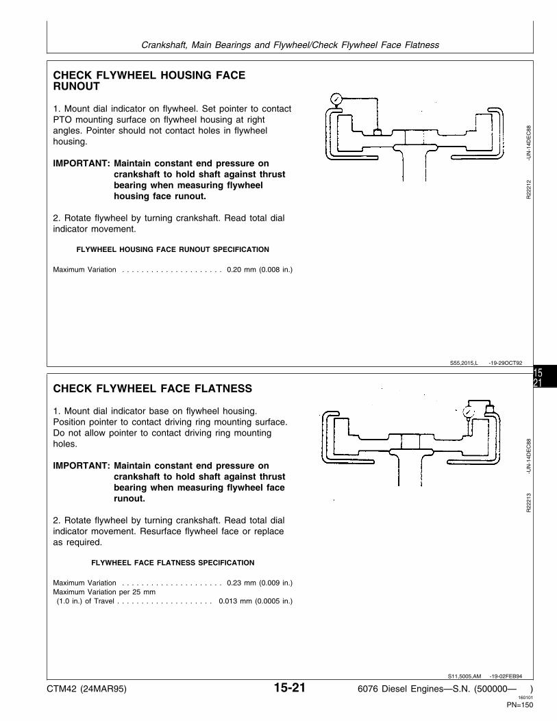
CHECK FLYWHEEL HOUSING FACERUNOUT
1. Mount dial indicator on flywheel. Set pointer to contactPTO mounting surface on flywheel housing at rightangles. Pointer should not contact holes in flywheelhousing.
IMPORTANT: Maintain constant end pressure oncrankshaft to hold shaft against thrustbearing when measuring flywheelhousing face runout.
2. Rotate flywheel by turning crankshaft. Read total dialindicator movement.
FLYWHEEL HOUSING FACE RUNOUT SPECIFICATION
Maximum Variation . . . . . . . . . . . . . . . . . . . . . 0.20 mm (0.008 in.)
R22
212
-UN
-14D
EC
88
CHECK FLYWHEEL FACE FLATNESS
1. Mount dial indicator base on flywheel housing.Position pointer to contact driving ring mounting surface.Do not allow pointer to contact driving ring mountingholes.
IMPORTANT: Maintain constant end pressure oncrankshaft to hold shaft against thrustbearing when measuring flywheel facerunout.
2. Rotate flywheel by turning crankshaft. Read total dialindicator movement. Resurface flywheel face or replaceas required.
FLYWHEEL FACE FLATNESS SPECIFICATION
Maximum Variation . . . . . . . . . . . . . . . . . . . . . 0.23 mm (0.009 in.)Maximum Variation per 25 mm (1.0 in.) of Travel . . . . . . . . . . . . . . . . . . . . 0.013 mm (0.0005 in.)
R22
213
-UN
-14D
EC
88
S55,2015,L -19-29OCT92
S11,5005,AM -19-02FEB94
Crankshaft, Main Bearings and Flywheel/Check Flywheel Face Flatness
CTM42 (24MAR95) 15-21 6076 Diesel Engines—S.N. (500000— )160101
PN=150
1521

CHECK PILOT BEARING BORECONCENTRICITY
1. Mount dial indicator on flywheel housing face andposition pointer to contact ID of pilot bearing bore inflywheel.
2. Rotate flywheel by turning crankshaft. Read total dialindicator movement.
BEARING BORE CONCENTRICITY SPECIFICATION
Maximum Variation . . . . . . . . . . . . . . . . . . . . 0.127 mm (0.005 in.)
R22
214
-UN
-14D
EC
88
REMOVE FLYWHEEL
NOTE: SAE 1 and SAE 2 flywheel housings MUST BEremoved before flywheel can be removed fromengine. See REMOVE SAE 1 AND SAE 2FLYWHEEL HOUSING, later in this group.
N CAUTION: Flywheel is heavy. Plan a properlifting procedure to avoid personal injury.
1. Remove two flywheel attaching cap screws (A), andinstall two pilot studs in their place.
2. Remove remaining cap screws, remove drive hub (ifequipped), and carefully pull flywheel from crankshaft.
4. Check condition of dowel pin in crankshaft rear flange.Dowel pin must not be cracked or chipped. Measureprotrusion of dowel pin from face of flange. If dowel pinis damaged, or protrusion is not within specifications,replace dowel pin.
NOTE: When replacing dowel pin, crankshaft must beremoved to prevent damage to crankshaft thrustbearings.
CRANKSHAFT DOWEL PIN SPECIFICATIONS
Protrusion From Crankshaft Rear Flange . . . . . . . . . . . . . . . . 13.5—14.5 mm (0.53—0.57 in)
RG
3836
-U
N-1
4DE
C88
S55,2015,M -19-08MAR94
RG,CTM42,G15,52-19-16AUG94
Crankshaft, Main Bearings and Flywheel/Remove Flywheel
CTM42 (24MAR95) 15-22 6076 Diesel Engines—S.N. (500000— )160101
PN=151
1522

REMOVE SAE 1 AND SAE 2 FLYWHEELHOUSING
N CAUTION: Flywheel housing is heavy. Plan aproper lifting procedure to avoid personalinjury.
1. Remove attaching cap screws.
2. Remove flywheel housing.
3. Inspect mounting holes in flywheel housing for threaddamage.
REMOVE SAE 3 FLYWHEEL HOUSING
NOTE: The flywheel MUST be removed before removingthe SAE 3 flywheel housing. See REMOVEFLYWHEEL earlier in this group.
N CAUTION: Flywheel housing (A) is heavy. Plana proper lifting procedure to avoid personalinjury.
1. Remove flywheel housing attaching cap screws.
2. Remove flywheel housing.
3. Inspect mounting holes in flywheel housing for threaddamage.
RG
5005
-U
N-1
4DE
C88
S11,2015,GK -19-29OCT92
S11,2015,GO -19-29OCT92
Crankshaft, Main Bearings and Flywheel/Remove SAE 3 Flywheel Housing
CTM42 (24MAR95) 15-23 6076 Diesel Engines—S.N. (500000— )160101
PN=152
1523

REPLACE FLYWHEEL RING GEAR
N CAUTION: Oil fumes or oil can ignite above193˚C (380˚F). Use a thermometer and do notexceed 182˚C (360˚F). Do not allow a flame orheating element to be in direct contact with theoil. Heat the oil in a well ventilated area. Plan asafe handling procedure to avoid burns.
1. If ring gear is damaged, place the flywheel on a solidflat surface.
2. Remove ring gear with a brass drift and hammer.
IMPORTANT: If flame heat is used, be sure gear isheated uniformly around circumference.DO NOT OVERHEAT. Overheating maydestroy original heat treatment of gear.SEE CAUTION.
3. Heat new ring gear to 148˚C (300˚F) using eitherheated oil, oven heat, or flame heat.
4. Install ring gear against shoulder of flywheel sochamfered side (A) is on engine side of flywheel.
T90
596
-UN
-14O
CT
88R
G38
38
-
UN
-14O
CT
88
S11,2015,FX -19-16SEP92
Crankshaft, Main Bearings and Flywheel/Replace Flywheel Ring Gear
CTM42 (24MAR95) 15-24 6076 Diesel Engines—S.N. (500000— )160101
PN=153
1524

REPLACE REAR OIL SEAL HOUSING (6076HRW33, 34, AND 35 ENGINES)—ENGINEINSTALLED IN VEHICLE
6076HRW33, 34, and 35 Engines used in 8100,8200, and 8300 tractors are equipped with frontframe/oil sump, refer to TM1575 (8100, 8200, 8300,and 8400 Tractors—Repair) for access to frontframe/oil sump-to-engine block cap screws.
IMPORTANT: Remove rear oil seal housing (A) forreplacement purposes only, it is notnecessary to remove seal housingfor rear seal and wear sleevereplacement.
To Remove Rear Oil Seal Housing:
NOTE: Refer to TM1575 for access to rear crankshaftseal housing area.
1. Remove flywheel cover.
2. Remove transmission input shaft coupler bolts andpry coupler rearward.
NOTE: Use a set screw to separate damper fromflywheel, if necesssary.
3. Remove torsional damper from flywheel.
4. Remove flywheel from right side of tractor.
5. Back out all front frame/oil sump-to-engine blockcap screws 9.5 mm (0.38 in.)
6. Slowly lift engine block assembly approximately 6.4mm (0.25 in.) using safety approved lifting equipment.
IMPORTANT: The rear oil seal housing must notbe “dragged” horizontally while incontact with front frame/oil sumpgasket. Doing so may damagegasket sealing bead.
7. Remove rear oil seal housing (A).
8. Remove rear wear sleeve from crankshaft flangewith JDG790 Wear Sleeve Puller Kit as detailedearlier in this group. Clean flange with emery cloth.
To Install Rear Oil Seal Housing:
1. Install rear oil seal housing and check runout. (SeeINSTALL CRANKSHAFT REAR OIL SEAL HOUSINGand CHECK OIL SEAL HOUSING RUNOUT, later inthis group.)
2. Carefully lower engine onto locating dowels of frontframe/oil sump.
3. Tighten front frame/oil sump cap screws asdetailed in Group 20, Lubrication System of thismanual (See TIGHTEN CAP SCREWS ON FRONTFRAME/OIL SUMP) or TM1575.
4. Install a new rear oil seal and wear sleeveassembly. (See INSTALL CRANKSHAFT REAR OILSEAL AND WEAR SLEEVE, WITHOUT ENGINEDISASSEMBLY, earlier in this group.)
5. Install flywheel. (See INSTALL FLYWHEEL, later inthis group.)
6. Install torsional damper onto flywheel. (SeeTM1575.)
7. Pull transmission input shaft coupler forward, installcap screws and tighten to specified torque. (SeeTM1575.)
8. Install flywheel cover. (See TM1575.)
9. Start engine and chack for leaks.
RG,CTM42,G15,48-19-21MAR95
Crankshaft, Main Bearings and Flywheel/Replace Rear Oil Seal Housing (6076HRW33, 34, and 35 Engines)
CTM42 (24MAR95) 15-25 6076 Diesel Engines—S.N. (500000— )160101
PN=154
1525

REMOVE REAR OIL SEAL HOUSING ANDWEAR SLEEVE (WITH ENGINEDISASSEMBLED)
These instructions are for use when the oil seal housingand oil pan will be removed. Refer to REMOVECRANKSHAFT REAR OIL SEAL AND WEAR SLEEVE(WITH OIL SEAL HOUSING INSTALLED), earlier in thisgroup, for instructions without the oil seal housing and oilpan being removed.
1. Remove rear oil seal housing (A).
IMPORTANT: If rear oil seal is replaced, also replacerear wear sleeve. The wear sleeve doesnot have to be removed to removecrankshaft.
2. Rear oil seal (B) will come off with housing. Use asmall punch and hammer to remove oil seal. Discardseal.
RG
3839
-U
N-1
4DE
C88
RG,CTM42,G15,14-19-16AUG94
Crankshaft, Main Bearings and Flywheel/Remove Rear Oil Seal Housing and Wear Sleeve
CTM42 (24MAR95) 15-26 6076 Diesel Engines—S.N. (500000— )160101
PN=155
1526

IMPORTANT: The preferred method of removing thewear sleeve is with JDG790 Rear WearSleeve Puller. When removing wearsleeve with a chisel, DO NOT gougecrankshaft flange. Nicks or burrsshould be removed with a medium-gritstone. Polishing cloth (180-grit or finer)may also be used when a stone is notavailable.
Rear wear sleeve can be removed using one of thefollowing procedures: These procedures may also befollowed when crankshaft has been removed fromengine.
• Use JDG790 Wear Sleeve Puller to remove wearsleeve from crankshaft flange, as described earlier in thisgroup.
• Use the ball side of a ballpeen hammer and tap wearsleeve across its width in a straight line (to deform andstretch sleeve).
• Score but do not cut the wear sleeve in several placesaround OD with a blunt chisel.
Remove wear sleeve from crankshaft flange. Cleanflange with a light file and emery cloth.
REMOVE CRANKSHAFT MAIN BEARINGS
IMPORTANT: Before removing main bearing caps (A),check for proper torque on all mainbearings. Also, check each bearing capto make sure they are numbered forreassembly on the same numberedmain bearing bosses. Keep matchedbearing inserts with their respectivemain bearing cap for comparison withcrankshaft journal (surface) from whichremoved.
NOTE: When removing main bearings and caps, leaveNo. 1 and 7 main bearing caps installed until allof the connecting rod caps have been removed.
RG
5832
-U
N-1
2AU
G91
RG,CTM42,G15,54-19-02APR93
RG,CTM42,G15,16-19-29OCT92
Crankshaft, Main Bearings and Flywheel/Remove Crankshaft Main Bearings
CTM42 (24MAR95) 15-27 6076 Diesel Engines—S.N. (500000— )160101
PN=156
1527

1. Loosen main bearing cap screws and washers.
2. Remove main bearing caps by extending cap screws(A) and forcing heads of screws together. Wiggle bearingcap (B) back and forth while applying an upward forcewith cap screws until free from main bearing capsupport.
3. Use PLASTIGAGE to measure oil clearance on eachmain bearing as they are removed. See CHECK MAINBEARING OIL CLEARANCE later in this group.
RG
5833
-U
N-1
2AU
G91
CHECK MAIN BEARING CLEARANCE
The use of PLASTIGAGE will determine wear but will notdetermine condition of the bearing or journal surfaces.
1. Put a strip of PLASTIGAGE in the center of the mainbearing cap (with insert) about three-fourths of the widthof the bearing.
2. Use oil (SAE30) on PLASTIGAGE to preventsmearing.
3. Install cap and tighten to 203 N·m (150 lb-ft).
4. Remove cap and compare width of PLASTIGAGE withscale provided on wrapper to determine oil clearance.
MAIN BEARING CLEARANCE SPECIFICATIONS
Main Bearing-to-Journal Clearance . . . . . . . . . . . . 0.030—0.107 mm(0.0012—0.0042 in.)
T42
576N
Y
-U
N-0
9NO
V88
RG,CTM42,G15,17-19-14SEP94
S11,0403,Z -19-08AUG94
Crankshaft, Main Bearings and Flywheel/Check Main Bearing Clearance
CTM42 (24MAR95) 15-28 6076 Diesel Engines—S.N. (500000— )160101
PN=157
1528

REMOVE CRANKSHAFT
1. Rotate crankshaft using JDE81-1 Flywheel TurningTool until connecting rod caps can be removed easily.You will be able to remove two rod caps at eachposition.
2. Remove all connecting rod caps (A) with bearings (B),then remove No. 1 and 7 main bearing caps andbearings. See REMOVE PISTONS AND CONNECTINGRODS in Group 10.
N CAUTION: Crankshaft is very heavy. Plan aproper handling procedure to avoid injury.
NOTE: Install a screw on each end of crankshaft to aidin lifting crankshaft.
3. Attach a lifting strap to crankshaft. Using proper liftingequipment, carefully raise crankshaft out of cylinderblock.
4. Clean crankshaft, especially oil passages, usingsolvent and compressed air.
5. Put crankshaft on clean V-blocks.
If wear sleeve has not been removed from crankshaft,the following procedures may be used. However,removing wear sleeve using JDG790 Wear Sleeve PullerKit while crankshaft is installed in engine is the preferredmethod.
• Use JDG790 Wear Sleeve Puller to remove wearsleeve from crankshaft, as described earlier in thisgroup. Position crankshaft rod journals in V-blocks sothat crankshaft does not rotate while removing wearsleeve.
• Use the ball side of a ball peen hammer and tap wearsleeve across its width in a straight line (to deform andstretch sleeve).
• Score (A), but do not cut, the wear sleeve in severalplaces around OD with a blunt chisel.
RG
5806
-U
N-1
2AU
G91
RG
5834
-U
N-1
2AU
G91
RG,CTM42,G15,18-19-16AUG94
Crankshaft, Main Bearings and Flywheel/Remove Crankshaft
CTM42 (24MAR95) 15-29 6076 Diesel Engines—S.N. (500000— )160101
PN=158
1529

INSPECT CRANKSHAFT
NOTE: If the crankshaft damper damage wasdiscovered during teardown, it isrecommended that the crankshaft bemagna-fluxed. This will verify whether or not ithas microscopic cracks or fissures. (SeeINSPECT VIBRATION DAMPER, earlier inthis group.) The vibration damper should bereplaced whenever the crankshaft is replaced.
1. Thoroughly clean crankshaft. Clear restrictions fromall oil passages.
2. Inspect crankshaft for signs of load stress, cracks,or scratches on journals. Also check each journal forevidence of excessive overheating or discoloration. Ifeither condition exists, replace crankshaft since heattreatment has probably been destroyed.
3. Inspect (front) crankshaft gear and (rear) oil pumpdrive gear for cracks, chipped teeth, or excess wear.Replace gear(s) as required. (See REPLACE FRONTCRANKSHAFT GEAR and REPLACE CRANKSHAFTOIL PUMP DRIVE GEAR, later in this group.)
4. Inspect the keyway for evidence of cracks or wear.Replace crankshaft as necessary.
5. Carefully inspect the rear hub of the crankshaft inthe area of the wear sleeve contact surface forevidence of a rough or grooved condition. Anyimperfections in this area will result in oil leakage.Slight ridges may be cleaned up with emery cloth andcrocus cloth.
6. Check each journal for evidence of excessiveoverheating or discoloration. If either condition exists,replace crankshaft since heat treatment has probablybeen destroyed.
RG,CTM42,G15,93-19-16AUG94
Crankshaft, Main Bearings and Flywheel/Inspect Crankshaft
CTM42 (24MAR95) 15-30 6076 Diesel Engines—S.N. (500000— )160101
PN=159
1530

7. Carefully check the crankshaft for cracks in the areaof rod journal oil holes (A) and at journal fillets (B).Replace crankshaft if any cracks are found.
IMPORTANT: Small cracks may not be visible to theeye. Use a method such as theFluorescent Magnetic Particle method.This method magnetizes the crank,employs magnetic particles which arefluorescent and glow under “blacklight”. The crankshaft must bede-magnetized after the test.
8. Check condition of dowel pin in crankshaft rear flange.Dowel pin must not be cracked or chipped. Measureprotrusion of dowel pin from face of flange. If dowel pinis damaged, or protrusion is not within specifications,replace dowel pin. If dowel pin is damaged, also inspectflywheel for damage.
NOTE: If replacing dowel pin, crankshaft must beremoved to prevent damage to crankshaft thrustbearings.
CRANKSHAFT DOWEL PIN SPECIFICATIONS
Dowel Pin Protrusion From Rear Flange . . . . . . . . . . . . . . . . 13.5—14.5 mm (0.53—0.57 in.)
RG
5093
-U
N-1
5DE
C88
RG,CTM42,G15,94-19-16AUG94
Crankshaft, Main Bearings and Flywheel/Inspect Crankshaft
CTM42 (24MAR95) 15-31 6076 Diesel Engines—S.N. (500000— )160101
PN=160
1531

MEASURE ASSEMBLED ID OF BEARINGSAND OD OF CRANKSHAFT JOURNALS
1. With crankshaft removed from engine, install mainbearing inserts and caps (be sure inserts are installedcorrectly).
2. Tighten main bearing cap screws to 203 N·m (150lb-ft).
3. Measure I.D. of all bearings with an insidemicrometer.
MAIN BEARING ID SPECIFICATIONS
With Bearing . . . . . . . . . . . . . . . . . . . . . . . . . 85.705—85.755 mm(3.3742—3.3762 in.)
Without Bearing . . . . . . . . . . . . . . . . . . . . . . . 92.125—92.151 mm(3.627—3.628 in.)
NOTE: Inspect and measure assembled ID of connectingrod bearings. Compare measurements withconnecting rod journal OD on crankshaft. (SeeGroup 10.)
RG
5835
-U
N-1
2AU
G91
4. Measure OD of all respective crankshaft journals atseveral points around journal.
CRANKSHAFT SPECIFICATIONS
OD of Main Bearing Journal . . . . . . . . . . . . . . . . . . 85.649—85.674(3.3720—3.3730 in.)
NOTE: If engine has previously had a major overhauland undersized bearing inserts were used, abovelisted ID and OD dimensions may not be thesame as those recorded. However, oil clearanceshould be within specifications. Oil clearance is0.030—0.107 mm (0.0012—0.0042 in.).
Use crankshaft journal OD measurements to determine ifjournal is out-of-round or tapered.
CRANKSHAFT WEAR SPECIFICATIONS
Journal Taper Per 25.4 mm (1.0 in.) of Journal Length . . . . . . . . . . . . . . . . . . . . . 0.0025 mm (0.0001 in.)
Journal Out-of-Roundness . . . . . . . . . . . . . . 0.025 mm (0.0010 in.)
RG
1808
-U
N-1
4DE
C88
RG,CTM42,G15,34-19-16AUG94
S11,0403,AD -19-17AUG94
Crankshaft, Main Bearings and Flywheel/Measure Assembled ID of Bearings And OD Of Crankshaft Journals
CTM42 (24MAR95) 15-32 6076 Diesel Engines—S.N. (500000— )160101
PN=161
1532

MAIN BEARING CAP LINE BORE SPECIFICATION
1. With crankshaft removed from cylinder block, installmain bearing caps without bearing inserts.
2. Tighten main bearing cap screws to 203 N·m (150lb-ft).
3. Measure ID of all bearing caps, at severallocations, with an inside micrometer.
If any main bearing cap assembled ID is not withinspecification, blank (generic) bearing caps areavailable and must be line bored to specification.Replace individual bearing caps as needed.
IMPORTANT: Main bearing cap line boring shouldbe done ONLY by experiencedpersonnel on equipment capable ofmaintaining bore specifications.
MAIN BEARING CAP BORE SPECIFICATIONS
ID Without Bearings (Standard) . . . . . . . . . . 92.125—92.151 mm(3.627—3.628 in.)
Maximum Bore Diameter Variation . . . . . . . . . . . . . . . 0.013 mm(0.0005 in.)
Maximum Bore Diameter Taper . . . . . . . . . . . . . . . . . 0.013 mm(0.0005 in.)
Maximum Straightness Variation(Any Bore-to-Adjacent Bore) . . . . . . . . . . . . . . . . . . . 0.038 mm
(0.0015 in.)
Maximum Straightness Variation(5 Center Bores-to-End Bores) . . . . . . . . . . . . . . . . . . 0.08 mm
(0.003 in.)
Centerline of Bore-to-Top Deck . . . . . . . . . . 352.35—352.50 mm(13.872—13.878 in.)
S11,2515,BY -19-21MAR95
Crankshaft, Main Bearings and Flywheel/Main Bearing Cap Line Bore Specifications
CTM42 (24MAR95) 15-33 6076 Diesel Engines—S.N. (500000— )160101
PN=162
1533

CRANKSHAFT GRINDING GUIDELINES
IMPORTANT: Crankshaft grinding should be doneONLY by experienced personnel onequipment capable of maintainingcrankshaft size and finishspecifications.
In addition to the standard size main and connectingrod bearings, 0.05, 0.25, 0.51 and 0.76 mm (0.002,0.010, 0.020 and 0.030 in.) undersize bearings areavailable. If journals are tapered, out-of-round, scoredor damaged, grind the crankshaft and install theproper undersize bearings.
NOTE: The 0.05 mm (0.002 in.) undersize bearingsare used normally to compensate for slightun-even wear on crankshafts. Regrinding isusually unnecessary when this size bearing isused.
IMPORTANT: If undersize bearings are used,check bearing clearance afterbearing caps have been tightened tospecified torque. If undersizebearings are too tight and clearanceis not within specifications, thejournal and bearing will be wipedclean of all oil. This would result inpremature wear of parts.
If the crankshaft is to be reground, use the followingrecommended procedure:
1. Compare the crankshaft journal measurementstaken during inspection and determine the size whichthe journals are to be reground.
2. If one or more main or connecting rod journalsrequire grinding, then grind all of the main journals orall of the connecting rod journals to the samerequired size.
3. All journal fillets radii must be free of any sharpgrind marks or scratches. The fillet must blendsmoothly into the journal and crank cheek. Check theradius with a fillet gage.
IMPORTANT: Care must be taken to avoidlocalized heating which oftenproduces grinding cracks.
S11,2015,DM -19-16AUG94
Crankshaft, Main Bearings and Flywheel/Crankshaft Grinding Guidelines
CTM42 (24MAR95) 15-34 6076 Diesel Engines—S.N. (500000— )160101
PN=163
1534

CRANKSHAFT GRINDING GUIDELINES—CONTINUED
4. Cool the crankshaft while grinding by using coolantgenerously. DO NOT crowd the grinding wheel intothe work.
IMPORTANT: Grind crankshaft with journalsturning counterclockwise, as viewedfrom the front end of crankshaft.Lap or polish journals in oppositedirection of grinding.
5. Polish or lap the ground surfaces to the specifiedfinish to prevent excessive wear of the journals. (SeeCRANKSHAFT GRINDING SPECIFICATIONS, later inthis group.)
NOTE: Production crankshafts are induction hardenedand shotpeened at the factory. Fieldshotpeening is not recommended due to theequipment required and part geometry.
6. If the thrust surfaces of the crankshaft are worn orgrooved excessively, regrind and polish. Maintain thespecified radius between each thrust surface and thebearing journal. An oversize thrust washer setcontaining one standard washer and two 0.18 mm(0.007 in.) oversize washers is available. (SeeTHRUST BEARING NEW PART SPECIFICATIONS,later in this group.)
NOTE: When thrust surfaces are reground and anoversize washer is used, crankshaft end playspecification must be maintained to within0.038—0.380 mm (0.0015—0.0150 in.) (SeeCHECK CRANKSHAFT END PLAY, earlier inthis group.)
7. Stone the edge of all oil holes in the journalsurfaces smooth to provide a radius of approximately1.50 mm (0.060 in.).
8. When finished grinding, inspect the crankshaft forcracks with the Florescent Magnetic Particle method,or similar method.
9. De-magnetize the crankshaft.
10. Thoroughly clean the crankshaft and oil passageswith solvent. Dry with compressed air.
S11,2015,HD -19-08MAR94
Crankshaft, Main Bearings and Flywheel/Crankshaft Grinding Guidelines
CTM42 (24MAR95) 15-35 6076 Diesel Engines—S.N. (500000— )160101
PN=164
1535

THRUST BEARING NEW PARTSPECIFICATIONS
IMPORTANT: Install thrust bearing in cylinder blockand tighten to specification beforeregrinding or polishing thrust surfacesto assure that all surface on bearingand on block web are correctly aligned.
THRUST BEARING NEW PART SPECIFICATION
Thrust Washer Clearance Base Circle Diameter . . . . . . . . . . . 123.70—125.30 mm (4.87—4.93 in.)
Thrust Surface Thickness . . . . . . . . . . . . . . . . . . 37.44—37.54 mm(1.474—1.478 in.)
Relief Angle . . . . . . . . . . . . . . . . . . . . . . . . . . . . . . . . . . . . . 45˚
Bearing Overall Width . . . . . . . . . . . . . . . . . . . . 39.16—39.66 mm(1.542—1.561 in.)
Maximum Thrust Surface Runout . . . . . . . . . . 0.025 mm (0.0010 in.)
A—Thrust Washer Clearance Base Circle DiameterB—Thrust Surface ThicknessC—Relief AngleD—Bearing Overall Width
RG
5269
-U
N-1
4DE
C88
S55,2015,P -19-16AUG94
Crankshaft, Main Bearings and Flywheel/Thrust Bearing New Part Specifications
CTM42 (24MAR95) 15-36 6076 Diesel Engines—S.N. (500000— )160101
PN=165
1536

CRANKSHAFT GRINDING SPECIFICATIONS
ITEM SPECIFICATION
Engine Stroke . . . . . . . . . . . . . . . . . . . . . . . . . . . . . . . . . . . . . . . . . . . . . . . . . . . . 121 mm (4.75 in.)Main and Rod Journal Surface Finish . . . . . . . . . . . . . . . . . . . . . . . . . . . . . . . . . . . Lap 0.20 Um (8 AA)Thrust Journal Surface Finish . . . . . . . . . . . . . . . . . . . . . . . . . . . . . . . . . . . . . . . . Lap 0.40 Um (16AA)Rod Journal Fillet Radius . . . . . . . . . . . . . . . . . . . . . . . . . . . . . . . . . . 3.94—4.44 mm (0.155—0.175 in.)Main Journal Fillet Radius . . . . . . . . . . . . . . . . . . . . . . . . . . . . . . . . . 3.94—4.44 mm (0.155—0.175 in.)Thrust Journal Fillet Radius . . . . . . . . . . . . . . . . . . . . . . . . . . . . . . . . 3.56—4.06 mm (0.140—0.160 in.)Thrust Journal Width . . . . . . . . . . . . . . . . . . . . . . . . . . . . . . . . 44.387—44.487 mm (1.7475—1.7515 in.)
Bearing Size Crankshaft Main Journal OD Crankshaft Rod Journal OD
Standard . . . . . . . . . . . . . . . . . . . . 85.649—85.674 mm . . . . . . . . . . . . . . . . . 76.149—76.175 mm(3.3720—3.3730 in.) (2.9980—2.9990 in.)
0.05 mm (0.002 in.) . . . . . . . . . . . . 85.598—85.623 mm . . . . . . . . . . . . . . . . . 76.098—76.124 mmUndersize (3.3700—3.3710 in.) (2.9960—2.9970 in.)
0.25 mm (0.010 in.) . . . . . . . . . . . . 85.394—85.420 mm . . . . . . . . . . . . . . . . . 75.895—75.920 mmUndersize (3.3620—3.3630 in.) (2.9880—2.9890 in.)
0.51 mm (0.020 in.) . . . . . . . . . . . . 85.140—85.166 mm . . . . . . . . . . . . . . . . . 75.641—75.667 mmUndersize (3.3520—3.3530 in.) (2.9780—2.9790 in.)
0.76 mm (0.030 in.) . . . . . . . . . . . . 84.887—84.912 mm . . . . . . . . . . . . . . . . . 75.387—75.413 mmUndersize (3.3420—3.3430 in.) (2.9680—2.9690 in.)
S11,2015,HG -19-17AUG94
Crankshaft, Main Bearings and Flywheel/Crankshaft Grinding Specifications
CTM42 (24MAR95) 15-37 6076 Diesel Engines—S.N. (500000— )160101
PN=166
1537

REPLACE (CRANKSHAFT) OIL PUMP DRIVEGEAR
IMPORTANT: Protect all machined surfaces ofcrankshaft from grinding debris andweld spatter when removing old gearand installing new gear. DO NOT use acutting torch to remove failed gear.
1. Using a rotary grinding wheel or parting disc, grindweld beads (A) until flush with crankshaft flange.
2. Remove gear (B) by alternately striking gear at eachweld location using a brass drift and soft lead mallet.
3. After removal of gear, clean up OD of crankshaftflange and remove any burrs or remaining weld bead toeliminate interference when installing new gear.
N CAUTION: Oil fumes or oil can ignite above193˚C (380˚F). Use a thermometer and do notexceed 182˚C (360˚F). Do not allow a flame orheating element to be in direct contact with theoil. Heat the oil in a well-ventilated area. Plan asafe handling procedure to avoid burns.
4. Heat new gear to 148˚C (300˚F) using either heatedoil or oven heat.
IMPORTANT: DO NOT OVERHEAT GEAR. SEECAUTION. Overheating may alsodestroy original heat treatment of gear.
5. Drive gear onto crankshaft flange until flush againstshoulder.
NOTE: When driving oil pump drive gear onto crankshaftflange. The beveled edge of gear teeth shouldface the flywheel end of crankshaft.
6. Weld two 25.4 mm (1 in.) beads according toillustration using 1/8 in. diameter 7018 welding rod. Grindaway excess weld to eliminate the possibility ofinterference with cylinder block.
RG
5018
-U
N-1
4DE
C88
S11,2515,BG -19-08AUG94
Crankshaft, Main Bearings and Flywheel/Replace Crankshaft Oil Pump Drive Gear
CTM42 (24MAR95) 15-38 6076 Diesel Engines—S.N. (500000— )160101
PN=167
1538

REPLACE CRANKSHAFT GEAR
NOTE: Remove crankshaft gear for replacement only;it is not necessary to remove gear forcrankshaft removal.
1. Install JDG787 Thread Protector in nose ofcrankshaft.
2. Protect crankshaft wear sleeve surface withmasking tape.
3. Remove crankshaft gear using D01251AA* Pulleror an equivalent puller.
4. Discard gear after removal.
5. Remove Woodruff key from crankshaft keyway.
6. Remove masking tape.
IMPORTANT: Crankshaft gear must be installedon crankshaft before crankshaft isinstalled in engine, otherwisedamage to thrust bearings couldoccur.
N CAUTION: Oil fumes or oil can ignite above193˚C (380˚F). Use a thermometer and donot exceed 182˚C (360˚F). Do not allow aheating element to be in direct contact withthe oil. Heat the oil in a well-ventilated area.Plan a safe handling procedure to avoidburns.
7. Heat crankshaft gear (if removed) to 148˚C(300˚F), using either heated oil or oven heat.
IMPORTANT: If flame heat is used, be sure gearis heated uniformly aroundcircumference. DO NOT OVERHEAT.SEE CAUTION. Overheating mayalso destroy original heat treatmentof gear.
8. Install Woodruff key in crankshaft.
9. Place gear on crankshaft flange. Be sure key oncrankshaft is properly aligned with keyway in gear.
IMPORTANT: When installing gear, do not gougeor nick crankshaft flange.
10. Use JDH7 Driver to firmly seat gear againstcrankshaft flange.
11. Once gear cools, reseat gear using JDH7 Driver.
*Part of D01047AA 17-1/2 and 30-Ton Puller Set. RG,CTM61,G15,27-19-30APR93
Crankshaft, Main Bearings and Flywheel/Replace Crankshaft Gear
CTM42 (24MAR95) 15-39 6076 Diesel Engines—S.N. (500000— )160101
PN=168
1539

INSPECT THRUST BEARINGS
1. Check thrust surfaces of the thrust bearing and thethrust bearing journal on crankshaft and replace asnecessary.
Thrust bearings are available in each of the previouslymentioned insert undersizes. An oversize thrust washerset containing one regular size washer and two 0.18 mm(0.007 in.) oversize washers is also available.
NOTE: Thrust bearings must be installed with slotsfacing crankshaft flange. Two halves (A) and (C)go on cap side, not block.
A—Lower Rear Thrust WasherB—Upper Rear Thrust WasherC—Lower Front Thrust WasherD—Main Bearing Block Thrust BearingE—Main Bearing Cap Thrust BearingF—Large TangG—Small Tang
R24
545
-UN
-15D
EC
88
REMOVE AND CLEAN PISTON COOLINGORIFICES
1. Remove all six piston cooling orifices (A) and inspecteach cooling orifice to make sure it is not plugged ordamaged.
2. Use a soft wire and compressed air to clean orifice.Replace, if condition is questionable.
IMPORTANT: A piston cooling orifice failure couldcause damage to pistons, piston pins,rod pin bushings, and liners. If a pistoncooling orifice is left out, low or no oilpressure will result.
3. Install orifices and tighten to 11 N·m (8 lb-ft) (96lb-in.).
RG
5811
-U
N-1
2AU
G91
S11,0403,AF -19-08MAR94
RG,CTM42,G15,20-19-29OCT92
Crankshaft, Main Bearings and Flywheel/Remove and Clean Piston Cooling Orifices
CTM42 (24MAR95) 15-40 6076 Diesel Engines—S.N. (500000— )160101
PN=169
1540

INSTALL MAIN BEARINGS ANDCRANKSHAFT
IMPORTANT: If new main or thrust bearing inserts orthrust washers are installed, they mustbe installed as a matched set.
During assembly, apply a liberal coating of clean engineoil to:
—All main bearing webs in block
—Both sides of main bearing inserts, thrust bearing inserts, and thrust washers
—Entire OD of crankshaft main bearing journal No. 5 Main Thrust Bearing Assembly
1. Install six main bearing inserts in block except No. 5thrust bearing insert. Be sure locating tabs on inserts areproperly positioned with slot in block web.
IMPORTANT: Thrust washers (A,C) go on both sidesof bearing cap and thrust washer (B)on rear side of block web only with theslots facing the crankshaft.
2. Install No. 5 main thrust bearing insert (D) in block.Install upper thrust washer on bearing insert at rear ofblock web. Be sure tangs on washer are properlypositioned on thrust bearing insert.
3. Check to make sure that oil holes in main bearingweb are properly aligned with oil holes in bearing inserts.
A—Lower Rear Thrust WasherB—Upper Rear Thrust WasherC—Lower Front Thrust WasherD—Main Bearing Block Thrust BearingE—Main Bearing Cap Thrust BearingF—Large TangG—Small Tang
RG
5892
-U
N-1
3AU
G91
R24
545
-UN
-15D
EC
88
RG,CTM42,G15,21-19-14SEP94
Crankshaft, Main Bearings and Flywheel/Install Main Bearings and Crankshaft
CTM42 (24MAR95) 15-41 6076 Diesel Engines—S.N. (500000— )160101
PN=170
1541

INSTALL CRANKSHAFT
N CAUTION: Crankshaft is heavy. Plan aproper lifting procedure to avoid injuries.
1. Carefully position crankshaft onto main bearinginserts using a hoist and lift sling.
2. Dip entire main bearing cap screws in cleanengine oil and position them in the main bearingcaps. Apply a liberal amount of oil to bearing insertsin caps.
3. Install each bearing cap (B), bearings (C), and capscrews with washer (A) with the recesses and tabsaligned in matching order. Make sure bearing tabsalso match up before tightening cap screws.
NOTE: Make sure main bearing caps are installed onthe bearing bosses from which they wereremoved. The numbers stamped on the capsshould be on the same side as the numberson the block. If there is an arrow on cap,arrow must be on the camshaft side of theblock pointing towards the front of the engine.If bearing caps have been rebored, make surebearing caps have numbers stamped on them.
IMPORTANT: Do not use pneumatic wrench toinstall main bearing cap screws, asdamage may occur to threads.
4. Before tightening cap screws on main bearingcaps, align upper and lower thrust flanges on mainthrust bearings. Using a soft-face hammer, tapcrankshaft to the rear and then to the front to line upthrust bearing flanges.
5. Tighten No.’s 1, 2, 3, 4, 6 and 7 main bearing capscrews to 68 N·m (50 lb-ft). Hand-tighten No. 5 mainthrust bearing cap screws.
6. Gently pry crankshaft rearward and then forward toalign thrust washers on No. 5 main thrust bearing.
NOTE: DO NOT PRY crankshaft on No. 5 mainthrust bearing.
7. Tighten No. 5 main thrust bearing cap screws to68 N·m (50 lb-ft).
8. Tighten all main bearing cap screws (including No.5) to 203 N·m (150 lb-ft).
9. Turn crankshaft by hand. If it does not turn easily,disassemble parts and determine the cause.
10. Install connecting rod bearings and connectingrods caps. See INSTALL PISTONS ANDCONNECTING RODS in Group 10.
11. Check crankshaft for 0.038—0.380 mm(0.0015—0.0150 in.) end play.
12. Install oil pump and check drivegear-to-crankshaft clearance. See INSTALL ENGINEOIL PUMP in Group 20.
RG
5834
-U
N-1
2AU
G91
RG
3741
-U
N-1
4DE
C88
RG,CTM42,G15,22-19-03MAY93
Crankshaft, Main Bearings and Flywheel/Install Main Bearings and Crankshaft
CTM42 (24MAR95) 15-42 6076 Diesel Engines—S.N. (500000— )160101
PN=171
1542

INSTALL CRANKSHAFT REAR OIL SEALHOUSING
These instructions are for when oil seal housing and oilpan have been removed from cylinder block.
1. Make sure the OD of crankshaft flange (A) and ID ofseal housing (B) are free from nicks or burrs. Restoredamage surfaces with a fine file or emery cloth. Cleanwith compressed air.
2. Install oil seal housing (C) on cylinder block using anew gasket. Install all six cap screws with washers, andtighten finger tight.
RG
4637
-U
N-1
4DE
C88
RG,CTM42,G15,24-19-29OCT92
Crankshaft, Main Bearings and Flywheel/Install Crankshaft Rear Oil Seal Housing
CTM42 (24MAR95) 15-43 6076 Diesel Engines—S.N. (500000— )160101
PN=172
1543

IMPORTANT: Installation tools must be clean toassure proper positioning oncrankshaft flange and to hold runoutwithin specification so oil seal does notfail prematurely.
NOTE: For oil seal housings stamped R78124, useJDG748 Driver*. For oil seal housings stampedR115050, use JDG796 Alignment Tool.
3. Slip the proper tool (A) over crankshaft flange and intoseal housing bore to center oil seal housing.
The driver is designed to center the oil seal housing inrelation to crankshaft flange. However, the use of amagnetic base dial indicator is still recommended tomeasure the seal housing runout. Runout should notexceed 0.15 mm (0.006 in.).
4. Position bottom of oil seal housing flush (B) withcylinder block-to-oil pan mating surface. Tighten sealhousing cap screws to 27 N·m (20 lb-ft), using sequenceshown in bottom illustration, beginning with cap screwNo. 1.
5. Remove driver from end of crankshaft flange.
6. Check oil seal housing runout with a magnetic basedial indicator. See CHECK OIL SEAL HOUSINGRUNOUT, later in this group.
7. Trim off excess gasket material extending belowbottom of oil seal housing.
*From JDG476(85) Oil Seal and Wear Sleeve Installer Set.
RG
4638
-U
N-1
4DE
C88
RG
6427
-U
N-1
3OC
T92
RG,CTM42,G15,25-19-16AUG94
Crankshaft, Main Bearings and Flywheel/Install Crankshaft Rear Oil Seal Housing
CTM42 (24MAR95) 15-44 6076 Diesel Engines—S.N. (500000— )160101
PN=173
1544

CHECK OIL SEAL HOUSING RUNOUT
IMPORTANT: On service “short block” assemblies,rear oil seal housing runout is preset atthe factory. Do not remove housingfrom block.
1. Position magnetic base dial indicator (A) on end ofcrankshaft flange as shown. Preset dial indicator tip onID of oil seal housing bore (B).
2. Zero dial indicator and rotate crankshaft one fullrevolution, observe full indicator movement. Themaximum oil seal housing bore runout is 0.15 mm (0.006in.).
If runout exceeds specification, loosen cap screws andadjust housing to obtain an acceptable runout whilekeeping bottom of seal housing flush with oil pan matingsurface.
3. Recheck oil seal housing bore runout. If runout stillexceeds specification, oil seal housing bore is possiblydistorted and should be replaced. See INSTALLCRANKSHAFT REAR OIL SEAL HOUSING, earlier inthis group.
RG
5751
-U
N-0
5AU
G91
S11,2515,AK -19-16AUG94
Crankshaft, Main Bearings and Flywheel/Check Oil Seal Housing Runout
CTM42 (24MAR95) 15-45 6076 Diesel Engines—S.N. (500000— )160101
PN=174
1545

CRANKSHAFT REAR OIL SEAL AND WEARSLEEVE HANDLING PRECAUTIONS
Use the following precautions for handling seal and wearsleeve:
—Seal (A) and wear sleeve (B) are assembled. DO NOTSEPARATE. If parts become separated, discard andreplace with a new assembly. Attempts to reassemblewill cause the wear sleeve to damage the seal allowingengine oil to leak past seal.
—Always install seal and wear sleeve assemblyimmediately after removal from plastic bag to avoidpossible dirt contamination.
—No lubrication of any kind is to contact seal wheninstalling. Use of a lubricant may result in premature sealfailure.
—Install oil seal/wear sleeve assembly with the openside of seal and wear sleeve ID chamfer toward theengine. If seal is reversed, engine oil may be lostbecause grooves in oil seal lip would be incorrect withrespect to direction of crankshaft rotation.
—Oil seal/wear sleeve assembly MUST be installed withthe JDG476(85) Crankshaft Rear Oil Seal InstallationTool Set. Tool set consists of JDG477(85) Pilot andJDG478 Driver.
RG
5575
-U
N-0
7JU
L89
S11,2015,GP -19-08MAR94
Crankshaft, Main Bearings and Flywheel/Crankshaft Rear Oil Seal And Wear Sleeve Handling Precautions
CTM42 (24MAR95) 15-46 6076 Diesel Engines—S.N. (500000— )160101
PN=175
1546

INSTALL CRANKSHAFT REAR OIL SEALAND WEAR SLEEVE ASSEMBLY
1. Apply a light coating of LOCTITE 609 RetainingCompound, or equivalent, completely around the leadingedge of crankshaft flange. Wipe away any sealant thatmay have gotten on seal housing bore.
IMPORTANT: DO NOT allow sealant to get on anypart of wear sleeve OD or on oil seal.
2. Install JDG477(85) Pilot (A) on end of crankshaftusing the Allen head cap screws (B) supplied with toolset. Tighten cap screws securely.
IMPORTANT: Handle seal and wear sleeve assemblycarefully. If assembly becomesseparated, discard these parts andinstall a new assembly.
3. Carefully start oil seal/wear sleeve assembly (C) overJDG477(85) Pilot and crankshaft flange with open side ofseal toward engine.
IMPORTANT: When installing the JDG478 Driver onJDG477(85) Pilot and crankshaft flangeto position oil seal/wear sleeveassembly, locate crossbar of installer atright angle (90˚) to Allen head capscrews. This allows the crossbar tobottom on pilot, not head of capscrews, assuring correct installation.
RG
4639
-U
N-1
4DE
C88
4. Position JDG478 Driver (A) so that hole in the crossplate goes over threaded stud of pilot. Install washer andnut on stud.
5. Tighten nut to draw JDG478 Driver in until crossbarbottoms on JDG477(85) Pilot. When the tool bottoms,seal and wear ring assembly (B) will be correctlypositioned.
6. Remove JDG476(85) Tool Set from engine.
RG
4640
-U
N-1
4DE
C88
RG,CTM42,G15,26-19-29OCT92
RG,CTM42,G15,27-19-11JUN93
Crankshaft, Main Bearings and Flywheel/Install Crankshaft Rear Oil Seal and Wear Sleeve Assembly
CTM42 (24MAR95) 15-47 6076 Diesel Engines—S.N. (500000— )160101
PN=176
1547

INSTALL TIMING GEAR COVER
IMPORTANT: Tightening the timing gear cover capscrews in numerical sequence controlsthe total runout of the front crankshaftoil seal.
1. Install a new gasket on the engine block. Lightlygrease the gasket to hold it in place. Install timing gearcover (C). Tighten cap screws in sequence one throughnine (as shown) to 27 N·m (20 lb-ft).
2. Trim timing gear cover gasket flush with oil pangasket rail.
3. Lightly grease and install a new injection pump drivegear cover gasket on timing gear cover. Install cover (B).Tighten cap screws to 27 N·m (20 lb-ft).
4. Using a new O-ring, install magnetic pickup (A, ifequipped) in timing gear cover and tighten to 14 N·m (10lb-ft).
RG
5828
-U
N-1
2AU
G91
RG
5783
-U
N-1
3OC
T92
INSTALL FRONT WEAR SLEEVE
NOTE: Front wear sleeve can be installed with timinggear cover removed or installed.
1. Coat I.D. of new wear sleeve (if removed) withLOCTITE 609 Retaining Compound or equivalent.
2. Use the JDE3 Driver (B), large washer, and capscrew threaded in nose of crankshaft to press on wearsleeve (A).
RG
5879
-U
N-1
3AU
G91
RG,CTM42,G15,30-19-24MAR95
RG,CTM42,G15,29-19-29OCT92
Crankshaft, Main Bearings and Flywheel/Install Front Wear Sleeve
CTM42 (24MAR95) 15-48 6076 Diesel Engines—S.N. (500000— )160101
PN=177
1548

INSTALL CRANKSHAFT FRONT OIL SEAL(WITH TIMING GEAR COVER INSTALLED ONENGINE)
IMPORTANT: Whenever front oil seal is replaced, thewear sleeve MUST be replaced also.
1. Place JDG720-2 Seal Protector (A) on nose ofcrankshaft. Lubricate ID of front oil seal lips with cleanengine oil. Slide seal with spring side of seal facingengine onto seal protector. Be careful not to roll oil seallips.
2. Place JDG720-3 Seal Installer onto seal protectoragainst seal. Do not use spacer ring provided with toolset.
3. With nut and washer installed onto JDG720-1 ForcingScrew, thread forcing screw into nose of crankshaft untilit bottoms.
4. Tighten nut against crossplate of installer until installerbottoms onto front face of timing gear cover.
5. Remove installation tools. Verify seal is installedsquare in bore and that seal lips are not rolled on wearsleeve.
Oil seal should be 8.4 mm (0.33 in.) below front lip ofseal bore.
RG
6479
-U
N-2
6OC
T92
RG
6480
-U
N-2
6OC
T92
INSTALL DAMPER PULLEY ASSEMBLY
1. If vibration damper (A) was removed from damperpulley (B), install washer (C) and tighten cap screws to41 N·m (30 lb-ft).
NOTE: Vibration damper and pulley orientation may varydepending on specific engine application. Be suredamper and pulley are assembled in the sameorientation as when removed.
RG
3928
-U
N-1
4DE
C88
RG,CTM42,G15,43-19-03MAY93
S11,2015,DT -19-16AUG94
Crankshaft, Main Bearings and Flywheel/Install Damper Pulley Assembly
CTM42 (24MAR95) 15-49 6076 Diesel Engines—S.N. (500000— )160101
PN=178
1549

2. Make sure crankshaft Woodruff key is in place, withtab facing forward. Position damper pulley assembly (B)onto crankshaft.
3. Use hardened washer (part of damper assembly) andinsert a cap screw that is 25 mm (1 in.) longer thanoriginal cap screw (A). Tighten cap screw until it justbottoms out.
4. Remove cap screw and insert original cap screw withsame hardened washer.
5. Tighten cap screw to 230 N·m (170 lb-ft).
6. Install water bypass pipe.
RG
5882
-U
N-1
3AU
G91
INSTALL SAE 3 FLYWHEEL HOUSING
On SAE 1 and SAE 2 flywheel housings, the flywheelhousing is installed AFTER the flywheel.
N CAUTION: Flywheel housing (A) is heavy. Plana proper lifting procedure to avoid personalinjury.
1. On engines requiring a gasket between block andflywheel housing, inspect cylinder block and flywheelhousing gasket surfaces to see that they are clean.Scrape off all old gasket material. Install a new gasketwithout sealant between block and flywheel housing.
2. Install flywheel housing on cylinder block.
NOTE: Use new cap screws when installing flywheelhousing.
3. Dip threads of cap screw in engine oil beforeinstalling. Install and tighten cap screws to 407 N·m (300lb-ft).
RG
5005
-U
N-1
4DE
C88
RG,CTM42,G15,31-19-16AUG94
S11,2015,GL -19-29OCT92
Crankshaft, Main Bearings and Flywheel/Install SAE 3 Flywheel Housing
CTM42 (24MAR95) 15-50 6076 Diesel Engines—S.N. (500000— )160101
PN=179
1550

INSTALL FLYWHEEL
Two guide studs may be used to aid in flywheelinstallation.
N CAUTION: Flywheel is heavy. Plan a properhandling procedure to avoid personal injuries.
NOTE: ALWAYS use new cap screws when installingflywheel. Flywheel must be clean and free of oilbefore installing.
1. Coat threads of flywheel attaching cap screws withLOCTITE 242 or its equivalent.
2. Position flywheel over dowel pin (A) and install drivehub (if equipped). Start four cap screws. Remove guidestuds and install remaining cap screws.
3. Install remaining flywheel attaching cap screws.
4. Tighten flywheel attaching cap screws to 115 N·m (85lb-ft).
RG
4383
-U
N-1
4DE
C88
INSTALL SAE 1 AND SAE 2 FLYWHEELHOUSING
On SAE 3 flywheel housings, the housing MUST beinstalled BEFORE installing flywheel.
N CAUTION: Flywheel housing is heavy. Plan aproper lifting procedures to avoid personalinjury.
1. Scrape off all old gasket material. Install a new gasketwithout sealant between block and flywheel housing, ifequipped.
2. Install flywheel housing on cylinder block.
NOTE: ALWAYS use new cap screws when installingflywheel housing.
3. Dip threads of cap screw in engine oil beforeinstalling. Install and tighten cap screws to 407 N·m (300lb-ft).
S11,2020,L -19-29OCT92
S11,2015,GT -19-29OCT92
Crankshaft, Main Bearings and Flywheel/Install SAE 1 and SAE 2 Flywheel Housing
CTM42 (24MAR95) 15-51 6076 Diesel Engines—S.N. (500000— )160101
PN=180
1551

COMPLETE FINAL ASSEMBLY
1. Install fan assembly.
2. Install oil pan and fill with clean engine oil.
3. Fill cooling system with proper coolant after engineinstallation and perform engine break-in. (See PERFORMENGINE BREAK-IN in Group 05.)
S55,2015,Y -19-29OCT92
Crankshaft, Main Bearings and Flywheel/Complete Final Assembly
CTM42 (24MAR95) 15-52 6076 Diesel Engines—S.N. (500000— )160101
PN=181
1552
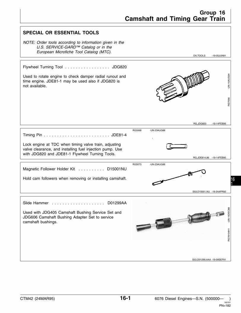
SPECIAL OR ESSENTIAL TOOLS
NOTE: Order tools according to information given in theU.S. SERVICE-GARD™ Catalog or in theEuropean Microfiche Tool Catalog (MTC).
Flywheel Turning Tool . . . . . . . . . . . . . . . . . JDG820
Used to rotate engine to check damper radial runout andtime engine. JDE81-1 may be used also if JDG820 isnot available.
RG
7056
-U
N-1
0AU
G94
Timing Pin . . . . . . . . . . . . . . . . . . . . . . . . . JDE81-4
Lock engine at TDC when timing valve train, adjustingvalve clearance, and installing fuel injection pump. Usewith JDG820 and JDE81-1 Flywheel Turning Tools.
RG5068 -UN-23AUG88
Magnetic Follower Holder Kit . . . . . . . . . . D15001NU
Hold cam followers when removing or installing camshaft.
RG5073 -UN-23AUG88
Slide Hammer . . . . . . . . . . . . . . . . . . . . D01299AA
Used with JDG405 Camshaft Bushing Service Set andJDG606 Camshaft Bushing Adapter Set to servicecamshaft bushings.
RG
7810
4H1
-U
N-1
5DE
C88
DX,TOOLS -19-05JUN91
RG,JDG820 -19-14FEB95
RG,JDE814,86 -19-14FEB95
S53,D15001,NU -19-24APR92
S53,D01299,AAA -19-09SEP91
Group 16Camshaft and Timing Gear Train
CTM42 (24MAR95) 16-1 6076 Diesel Engines—S.N. (500000— )160101
PN=182
161

Hub Puller Kit . . . . . . . . . . . . . . . . . . . . . . JDG721
Used with JDG787 Thread Protector to remove vibrationdamper pulley assembly on some engine applications.
RG
5763
-U
N-0
6AU
G91
Camshaft Bushing Service Set . . . . . . . . . . . JDG405
Used with JDG606 Camshaft Bushing Adapter Set andD01299AA Slide Hammer to service camshaft bushings.
NOTE: JDE6 Service Set may be used along withJDG602 Adapter Set if JDG405 is not available.
RG
4228
-U
N-2
7JA
N92
Camshaft Bushing Service Set . . . . . . . . . . . . . JDE6
Used with JDG602 Camshaft Bushing Adapter Set toservice camshaft bushings.
NOTE: JDG405 Service Set may be used along withJDG606 Adapter Set if JDE6 is not available.
R26
149N
-UN
-23A
UG
88
Camshaft Bushing Adapter Set . . . . . . . . . . . JDG602
Used with JDE6 Camshaft Bushing Service Set toservice camshaft bushings. JDG602 consists of JDG603Driver and JDG604 Receiver Cup.
RG
5336
-U
N-2
3AU
G88
RG,JDG721 -19-03MAY93
S53,JDG405,A -19-28APR92
S53,JDE6A -19-09SEP91
S53,JDG602 -19-09SEP91
Camshaft and Timing Gear Train/Special or Essential Tools
CTM42 (24MAR95) 16-2 6076 Diesel Engines—S.N. (500000— )160101
PN=183
162

Camshaft Bushing Adapter Set . . . . . . . . . . . JDG606
Used with JDG405 Camshaft Bushing Service Set andD01299AA Slide Hammer to service camshaft bushings.JDG606 consists of JDG607 Driver and JDG608 Pilot.
RG
5337
-U
N-2
8AU
G91
SERVICE EQUIPMENT AND TOOLS
NOTE: Order tools from the U.S. SERVICEGARD™ Catalog or from the European Microfiche Tool Catalog(MTC). Some tools may be available from a local supplier.
Name Use
D01207AA Puller Kit Used to remove vibration damper.
D01045AA Bushing, Bearing, and Seal Driver Master Set Used to install front oil seal in timing gearcover.
OTHER MATERIAL
Name Use
High Temperature Grease Lubricate camshaft lobes and thrust washers before(TY6333 OR TY6347) camshaft installation.
FEL-PRO® C-670 Molybdenum Disulfide Paste Lubricate camshaft nose to provide lubrication toaid in camshaft gear installation.
PERMATEX AVIATION (Form-A-Gasket No.3 ) Lubricate camshaft bore steel cap plug.(TY6299)
S53,JDG606 -19-09SEP91
RG,CTM42,G16,4 -19-10SEP91
RG,CTM42,G16,1 -19-29OCT92
Camshaft and Timing Gear Train/Other Material
CTM42 (24MAR95) 16-3 6076 Diesel Engines—S.N. (500000— )160101
PN=184
163

CAMSHAFT AND TIMING GEAR TRAIN SPECIFICATIONS
ITEM SPECIFICATION WEAR LIMIT
Camshaft End Play . . . . . . . . . . . . . . . . . . . . 0.0130—0.5000 mm 0.65 mm (0.026 in.)(0.0005—0.0200 in.)
Camshaft Thrust Washer Thickness . . . . . . . . . 2.24—2.34 mm ——(0.088—0.092 in.)
Camshaft Journal OD . . . . . . . . . . . . . . . . . . 66.987—67.013 mm ——(2.6373—2.6383 in.)
Camshaft Bushing ID . . . . . . . . . . . . . . . . . . . 67.076—67.102 mm ——(2.6408—2.6418 in.)
Camshaft Bushing-to-Journal Clearance . . . . . . 0.063—0.115 mm ——(0.0025—0.0045 in.)
Camshaft Gear-to-Injection Pump Drive Gear Backlash . . . . . . . . . . . . . 0.051 mm
(0.0020 in.) minimum ——Camshaft Bushing Bore in Block (without bushings) . . . . . . . . . . . . . . . . . . . 69.987—70.013 mm ——
(2.7554—2.7564 in.)
Maximum Runout of Camshaft Bore . . . . . . . . . 0.038 mm (0.0015 in.) ——
Maximum Runout of Camshaft Gear Thrust Surfaces . . . . . . . . . . . . . . . . . 0.10 mm (0.004 in.) ——
Camshaft Drive Gear-to-Crankshaft Gear Backlash . . . . . . . . . . . . . . . . . . . . . . 0.076 mm (0.0030 in.) minimum ——
Camshaft Lobe Lift: Intake . . . . . . . . . . . . . . . . . . . . . . . . . . . . 7.69—7.07 mm (0.303—0.307 in.) 7.19 mm (0.283 in.) Exhaust . . . . . . . . . . . . . . . . . . . . . . . . . . 8.25—8.35 mm (0.325—0.329 in.) 7.75 mm (0.305 in.)
Cam Follower OD . . . . . . . . . . . . . . . . . . . . . 17.33—17.35 mm(0.682—0.683 in.) ——
Cam Follower Bore Diameter in Block . . . . . . . 17.384—17.440 mm(0.6845—0.6865 in.) ——
Valve Lift at 0.00 mm (in.) Clearance: Intake . . . . . . . . . . . . . . . . . . . . . . . . . . . . 13.53—13.71 mm (0.533—0.540 in.) 12.65 mm (0.498 in.) Exhaust . . . . . . . . . . . . . . . . . . . . . . . . . . 14.52—14.70 mm (0.572—0.579 in.) 13.64 mm (0.537 in.)
Crankshaft Front Oil Seal Bore Runout . . . . . . . 0.254 mm (0.010 in.) maximum ——
Crankshaft Front Oil Seal Installed Depth (below front face of cover) . . . . . . . . . . . . . . 8.4 mm (0.33 in.) ——
RG,CTM42,G16,2 -19-16AUG94
Camshaft and Timing Gear Train/Camshaft and Timing Gear Train Specifications
CTM42 (24MAR95) 16-4 6076 Diesel Engines—S.N. (500000— )160101
PN=185
164

CAMSHAFT AND TIMING GEAR TRAIN SPECIFICATIONS—CONTINUED
TORQUES
Rocker Arm Shaft Clamps . . . . . . . . . . . . . . . . . . . . . . . . . . . . . . . . . . . . . . . . . . . . . . 75 N·m (55 lb-ft)
Rocker Arm Cover-to-Cylinder Head . . . . . . . . . . . . . . . . . . . . . . . . . . . . . . . . . . . 8 N·m (6 lb-ft) (72 lb-in.)
Timing Gear Cover-to-Cylinder Block . . . . . . . . . . . . . . . . . . . . . . . . . . . . . . . . . . . . . . . 27 N·m (20 lb-ft)
Injection Pump Gear Cover . . . . . . . . . . . . . . . . . . . . . . . . . . . . . . . . . . . . . . . . . . . . . 27 N·m (20 lb-ft)
Magnetic Pickup-to-Timing Gear Cover . . . . . . . . . . . . . . . . . . . . . . . . . . . . . . . . . . . . . . 14 N·m (10 lb-ft)
RG,CTM42,G16,3 -19-24MAR95
Camshaft and Timing Gear Train/Camshaft and Timing Gear Train Specifications
CTM42 (24MAR95) 16-5 6076 Diesel Engines—S.N. (500000— )160101
PN=186
165

CHECK VALVE LIFT
NOTE: Measuring valve lift can give an indication ofwear on camshaft lobes and cam followers orbent push rods.
IMPORTANT: For a more accurate measurement, it isrecommended that valve lift bemeasured at 0.00 mm (in.) valveclearance.
1. Remove turbocharger oil inlet line clamp and rockerarm cover. Loosen locknut on rocker arm. Set valveclearance at 0.00 mm (in.). Tighten locknut.
2. Put dial indicator tip on valve rotator. Be sure thatvalve is fully closed.
3. Check pre-set on dial indicator. Set dial indicatorpointer at zero.
4. Manually turn engine in running direction, using theengine rotation tools previously mentioned for checkingvalve clearance.
5. Observe dial indicator reading as valve is moved tofully open position.
VALVE LIFT SPECIFICATION AT 0.00 MM (IN.) CLEARANCE
Intake . . . . . . . . . . . . . . . . . . 13.53—13.71 mm (0.533—0.540 in.) Wear Tolerance . . . . . . . . . . . . . . . . . . . . . 12.65 mm (0.498 in.)
Exhaust . . . . . . . . . . . . . . . . . 14.52—14.70 mm (0.572—0.579 in.) Wear Tolerance . . . . . . . . . . . . . . . . . . . . . 13.65 mm (0.537 in.)
6. Follow same procedure for all remaining valves andadjust valve clearance to specification. (See CHECKAND ADJUST VALVE CLEARANCE in Group 05.)
RG
5789
-U
N-0
9AU
G91
RG,CTM42,G16,5 -19-16AUG94
Camshaft and Timing Gear Train/Check Valve Lift
CTM42 (24MAR95) 16-6 6076 Diesel Engines—S.N. (500000— )160101
PN=187
166

CHECK CAMSHAFT END PLAY
NOTE: Camshaft end play must be measured beforeremoving timing gear cover, as thrust washer inback side of timing gear cover limits camshaftend play.
1. Remove injection pump drive gear cover (shownremoved).
2. Install magnetic base dial indicator on front face ofcylinder block.
3. Position dial indicator tip on front face of camshaftgear, as shown. Set dial indicator to zero.
4. Move camshaft gear back and forth and observe endplay reading. Compare reading with specification givenbelow.
CAMSHAFT END PLAY SPECIFICATIONS
Camshaft End Play (NEW) . . . . . . . . . . . . . . . . . 0.013—0.500 mm(0.0005—0.0200 in.)
Maximum Allowable End Play . . . . . . . . . . . . . . . . . . . . . . 0.65 mm(0.0260 in.)
If end play is excessive, remove timing gear cover andcamshaft and measure thickness of thrust washers.
RG
5769
-U
N-0
6AU
G91
REMOVE DAMPER PULLEY AND TIMINGGEAR COVER
1. Drain oil (if not previously done), and remove oil pan.Remove oil pump if crankshaft is to be removed.
2. Remove cap screw and washer on damper pulley.
IMPORTANT: DO NOT use a jaw-type puller toremove vibration damper. Damagecould result to the damper. Never applythrust on outer ring of damper. Do notdrop damper or strike with a hammer.
3. Remove pulley and damper from crankshaft usingD01207AA Puller Set.
RG
5765
-U
N-0
6AU
G91
RG,CTM42,G16,12-19-29OCT92
RG,CTM42,G16,8 -19-29OCT92
Camshaft and Timing Gear Train/Remove Damper Pulley and Timing Gear Cover
CTM42 (24MAR95) 16-7 6076 Diesel Engines—S.N. (500000— )160101
PN=188
167

4. Remove magnetic pick-up (A, if equipped) andinjection pump drive gear cover (B).
5. Check camshaft end play. (See CHECK CAMSHAFTENDPLAY earlier in this group.)
IMPORTANT: Whenever timing gear cover isremoved, ALWAYS install a new frontoil seal.
6. Remove timing gear cover (C).
7. Remove front oil seal from timing gear cover. Install anew seal after timing gear cover is installed. SeeINSTALL FRONT OIL SEAL (WITH TIMING GEARCOVER INSTALLED ON ENGINE) in Group 15.
8. Remove front crankshaft wear sleeve.
RG
5766
-U
N-0
6AU
G91
MEASURE CAMSHAFT DRIVEGEAR-TO-CRANKSHAFT GEAR BACKLASH
Measure backlash between camshaft drive gear andcrankshaft gear in three (3) different positions around thecamshaft gear. Use a magnetic base dial indicator withindicator plunger resting on camshaft gear tooth.
CAMSHAFT DRIVE GEAR-TO-CRANKSHAFT GEAR BACKLASHSPECIFICATION
Camshaft Gear Backlash . . . . . . . . . . . . . 0.076 mm (0.003 in.) min.
Replace gears if backlash is not within specification.
RG
5770
-U
N-0
6AU
G91
RG,CTM42,G16,9 -19-16AUG94
RG,CTM42,G16,13-19-29OCT92
Camshaft and Timing Gear Train/Measure Camshaft Drive Gear-to-Crankshaft Gear Backlash
CTM42 (24MAR95) 16-8 6076 Diesel Engines—S.N. (500000— )160101
PN=189
168

REMOVE CAMSHAFT
NOTE: It is not necessary to remove cylinder head fromengine for camshaft removal. If push rods arebent or show excessive scuffing, it may benecessary to remove cylinder head for inspectionof block, head, cam lobes and cam followers.
1. Drain engine oil and coolant, if not previously done.
2. Disconnect turbocharger oil inlet line at turbochargeror oil conditioning housing.
3. Set engine at No. 1 cylinder’s “TDC-Compression”stroke with JDE81-4 Timing Pin. (See Group 05, CylinderHead and Valves.)
4. Remove rocker arm cover, rocker arm assembly andpush rods. Remove cylinder head, if desired. (See Group05, Cylinder Head and Valves.)
RG
5764
-U
N-0
6AU
G91
5. When removing camshaft with engine on rolloverstand, roll engine to a vertical position (horizontal shown)and hold cam followers away from camshaft lobes withD15001NU Magnetic Holding Set.
RG
5778
-U
N-0
6AU
G91
RG,CTM42,G16,32-19-29OCT92
RG,CTM42,G16,33-19-29OCT92
Camshaft and Timing Gear Train/Remove Camshaft
CTM42 (24MAR95) 16-9 6076 Diesel Engines—S.N. (500000— )160101
PN=190
169

6. Examine camshaft gear (A) and injection pump drivegear (B) for worn or damaged gear teeth. Gears shouldhave a minimum backlash of 0.051 mm (0.0020 in.).
NOTE: Timing marks on crankshaft and camshaft gearshould be aligned and No. 1 cylinder locked at“TDC Compression” stroke when removingcamshaft.
RG
5771
-U
N-0
6AU
G91
7. Carefully remove camshaft (B) from cylinder block sothat camshaft lobes do not drag in bores.
NOTE: Rotate camshaft carefully to aid in removing.
8. Remove thrust washer (A) from behind cam gears.
9. Remove cam followers.
RG
5772
-U
N-0
6AU
G91
RG,CTM42,G16,15-19-29OCT92
RG,CTM42,G16,16-19-29OCT92
Camshaft and Timing Gear Train/Remove Camshaft
CTM42 (24MAR95) 16-10 6076 Diesel Engines—S.N. (500000— )160101
PN=191
1610

REMOVE CAMSHAFT GEARS
NOTE: Camshaft gears are pressed onto the camshaft.Removal of gears from camshaft will requireapproximately a 10-ton press.
IMPORTANT: Prevent camshaft from striking floorwhen pushing camshaft nose out ofgear. Camshaft may be damaged if it isallowed to fall to the floor.
1. Support outer camshaft gear (A) in a press.
2. Remove outer gear from camshaft.
3. Support inner camshaft gear (B) in a press.
4. Remove inner gear from camshaft.
5. Clean camshaft and gears in solvent. Dry withcompressed air.
RG
5774
-U
N-0
6AU
G91
RG
5773
-U
N-0
6AU
G91
MEASURE THRUST WASHER THICKNESS
1. After removal of camshaft, check the two thrustwashers individually for proper thickness.
THRUST WASHER THICKNESS SPECIFICATIONS
Thrust Washer Thickness . . . . . . . . . . . . . . . . . . . . 2.24—2.34 mm(0.088—0.092 in.)
2. Replace washers if worn or damaged.
RG
5775
-U
N-0
6AU
G91
RG,CTM42,G16,17-19-29OCT92
RG,CTM42,G16,18-19-29OCT92
Camshaft and Timing Gear Train/Measure Thrust Washer Thickness
CTM42 (24MAR95) 16-11 6076 Diesel Engines—S.N. (500000— )160101
PN=192
1611

INSPECT AND MEASURE CAMSHAFTFOLLOWERS
1. Inspect camshaft followers for uneven wear ordamage. Also inspect corresponding camshaft lobe forwear or damage. Replace as necessary.
2. Measure follower OD and follower bore ID in cylinderblock.
CAMSHAFT FOLLOWER AND BORE SPECIFICATIONS
Camshaft Follower OD . . . . . . . . . . . . . . . . . . . . 17.33—17.35 mm(0.682—0.683 in.)
Camshaft Follower Bore ID in Block . . . . . . . . . . . . . . . . . . . . . . . . . 17.384—17.440 mm
(0.6845—0.6865 in.)
Replace cam followers that are not within specification.Replace cylinder block if any one cam follower bore isnot within specification.
RG
2745
-U
N-2
3FE
B89
VISUALLY INSPECT CAMSHAFT
1. Clean camshaft in solvent. Dry with compressed air.
2. Visually inspect camshaft lobes (A) and journals (B)for wear or damage. Replace as necessary. Newcamshaft followers can be used with old camshaft (ifcamshaft is serviceable). DO NOT reuse old camfollowers with a new camshaft.
NOTE: Very light score marks may be found, but areacceptable if valve lift is within specification.Pitting or galling dictates replacement. (SeeCHECK VALVE LIFT earlier in this group.)
RG
3500
-U
N-0
6AU
G91
RG,CTM42,G16,19-19-15SEP94
RG,CTM42,G16,20-19-29OCT92
Camshaft and Timing Gear Train/Visually Inspect Camshaft
CTM42 (24MAR95) 16-12 6076 Diesel Engines—S.N. (500000— )160101
PN=193
1612

MEASURE CAMSHAFT JOURNAL OD ANDBUSHING ID
1. Measure each camshaft journal OD. If camshaftjournal OD is not within specification, install a newcamshaft.
2. Measure each camshaft bushing ID when installed incylinder block.
Compare measurements with specs given below.Replace camshaft and bushings as needed.
CAMSHAFT JOURNAL AND BUSHING SPECIFICATIONS
Camshaft Journal Diameter (NEW) . . . . . . . . . . 66.987—67.013 mm(2.6373—2.6383 in.)
Camshaft Bushing ID (NEW) . . . . . . . . . . . . . . . 67.076—67.102 mm(2.6408—2.6418 in.)
T81
260
-UN
-07N
OV
88
MEASURE CAMSHAFT LOBE LIFT
1. Measure each camshaft lobe at its highest point andat its narrowest point. Subtract narrowest dimension fromhighest dimension to find camshaft lobe lift.
If camshaft lobe lift is not within the wear specificationon any one lobe, install a new camshaft.
CAM LOBE LIFT NEW PART SPECIFICATION
Intake Lobe Lift . . . . . . . . . . . . . . . . . . . . . . . . . . 7.69—7.79 mm(0.303—0.307 in.)
Wear Limit . . . . . . . . . . . . . . . . . . . . . . . . . 7.19 mm (0.283 in.)
Exhaust Lobe Lift . . . . . . . . . . . . . . . . . . . . . . . . . 8.25—8.35 mm(0.325—0.329 in.)
Wear Limit . . . . . . . . . . . . . . . . . . . . . . . . . 7.75 mm (0.305 in.)
T81
262
-UN
-01N
OV
88
RG,CTM42,G16,21-19-15SEP94
RG,CTM42,G16,22-19-16AUG94
Camshaft and Timing Gear Train/Measure Camshaft Lobe Lift
CTM42 (24MAR95) 16-13 6076 Diesel Engines—S.N. (500000— )160101
PN=194
1613

INSTALL CAMSHAFT GEARS
1. Support camshaft under first bearing journal in ahydraulic press.
2. Install Woodruff key (A). Lubricate camshaft nose withFEL-PRO® C-670 Molybdenum Disulfide Paste.
3. Set inner gear (B) on camshaft with thrust washersurface to the inside (toward the camshaft). AlignWoodruff key and keyway
4. Install gear onto nose of camshaft. Push inner gearon until tight against the camshaft bearing journal.
5. Set outer gear on camshaft with timing mark upward(away from the camshaft). Align Woodruff key andkeyway (C) of outer gear (D).
6. Push outer gear onto camshaft nose until tight againstinner gear.
A—Woodruff KeyB—Inner GearC—KeywayD—Outer Gear
RG
5777
-U
N-1
7SE
P91
RG
5776
-U
N-0
6AU
G91
7. Support each end of the camshaft on centers. Use adial indicator with plunger resting on the thrust surface ofthe camshaft gears.
8. Check the runout of the inner and outer gear thrustsurfaces.
CAMSHAFT GEAR THRUST SURFACE RUNOUT SPECIFICATIONS
Camshaft Gear Thrust Surface Runout . . . . . . . . . . . . . . . . 0.10 mm(0.004 in.)
RG,CTM42,G16,23-19-29OCT92
RG,CTM42,G16,24-19-23SEP91
Camshaft and Timing Gear Train/Install Camshaft Gears
CTM42 (24MAR95) 16-14 6076 Diesel Engines—S.N. (500000— )160101
PN=195
1614

SERVICE CAMSHAFT BUSHINGS USINGJDG602 ADAPTER SET
1. Inspect camshaft journals and bushings for wear ordamage. Measure cam journals and bushings todetermine if proper oil clearance exists. Replacecamshaft and/or bushings as necessary.
CAMSHAFT JOURNAL AND BUSHING NEW PART SPECIFICATION
Camshaft Bushing Bore in Block . . . . . . . . . . . . 69.987—70.013 mm(2.7554—2.7564 in.)
Journal OD . . . . . . . . . . . . . . . . . . . . . . . . . . 66.987—67.013 mm(2.6373—2.6383 in.)
Bushing ID . . . . . . . . . . . . . . . . . . . . . . . . . . . 67.076—67.102 mm(2.6408—2.6418 in.)
Oil Clearance . . . . . . . . . . . . . . . . . . . . . . . . . . 0.063—0.115 mm(0.0025—0.0045 in.)
NOTE: The front two bushings can be reached from thefront of the engine. The flywheel and rearcamshaft bore plug (G) must be removed toreach the other two bushings.
2. Remove camshaft bushings (F) using JDG603Bushing Driver (E) and JDG604 Receiver Cup (D) alongwith the components shown from JDE6 CamshaftBushing Replacement Set (A and C).
3. Tighten nut on end of bushing screw until bushing ispulled out of camshaft bushing bore. Inspect andmeasure camshaft bushing bore in block (B). Follow A—Bushing Screw (JDE6-1)
B—Cylinder Block Websame procedure for remaining bushings to be replaced.C—Lock Bushing (No. 25916)D—Receiver Cup (JDG604)E—Bushing Driver (JDG603)F—Camshaft BushingG—Camshaft Bore Plug
RG
5272
-U
N-0
6DE
C88
RG
5949
-U
N-3
0AU
G91
RG,CTM42,G16,30-19-15SEP94
Camshaft and Timing Gear Train/Service Camshaft Bushings using JDG602 Adapter Set
CTM42 (24MAR95) 16-15 6076 Diesel Engines—S.N. (500000— )160101
PN=196
1615

IMPORTANT: Oil holes in bushings and cylinderblock must be aligned after installationor oil starvation will occur. Theelongated hole in bushing must betoward the top. After installation, use asmall mirror with extension to be sureoil holes are properly aligned.
4. Slide a new camshaft bushing (F) onto JDG603Bushing Driver (E). Assemble driver and JDG604Receiver Cup (D) along with components shown fromJDE6 Camshaft Bushing Replacement Set (A and C).
5. Be sure bushing is started square in bore and oilholes are aligned with holes in block. Tighten nut to pullbushing in until it is properly positioned in bore.
6. Check bushing-to-cylinder block oil hole alignmentA—Bushing Screw (JDE6-1)using a small mirror with extension.B—Cylinder Block WebC—Lock Bushing (No. 25916)D—Receiver Cup (JDG604)E—Bushing Driver (JDG603)F—Camshaft Bushing
RG
5273
-U
N-0
6DE
C88
S55,2016,N -19-23SEP91
Camshaft and Timing Gear Train/Service Camshaft Bushings using JDG602 Adapter Set
CTM42 (24MAR95) 16-16 6076 Diesel Engines—S.N. (500000— )160101
PN=197
1616

SERVICE CAMSHAFT BUSHINGS USINGJDG606 ADAPTER SET
1. Inspect camshaft journals and bushings for wear ordamage. Measure cam journals and bushings todetermine if proper oil clearance exists. Replacecamshaft and/or bushings as necessary.
CAMSHAFT JOURNAL AND BUSHING NEW PART SPECIFICATIONS
Camshaft Bushing Bore in Block . . . . . . . . . . . . 69.987—70.013 mm(2.7554—2.7564 in.)
Journal OD . . . . . . . . . . . . . . . . . . . . . . . . . . 66.987—67.013 mm(2.6373—2.6383 in.)
Bushing ID . . . . . . . . . . . . . . . . . . . . . . . . . . . 67.076—67.102 mm(2.6408—2.6418 in.)
Oil Clearance . . . . . . . . . . . . . . . . . . . . . . . . . . 0.063—0.115 mm(0.0025—0.0045 in.)
NOTE: The front two bushings can be reached from thefront of the engine. The flywheel and rearcamshaft bore plug (G) must be removed toreach the other two bushings.
Lubricate O-ring on JDG608 Bushing Pilot withclean engine oil before installing in cylinder blockweb (C).
2. Remove camshaft bushing (B) using JDG607 BushingDriver (A), JDG408 Slide Hammer Adapter (D) (fromJDG405 Camshaft Bushing Service Set), JDG608
A—Bushing Driver (JDG607)Bushing Pilot (E), and D01299AA Slide Hammer (F).B—Camshaft BushingC—Cylinder Block WebNOTE: End bushing at front and rear of cylinder blockD—Slide Hammer Adapter (JDG408)
may be removed with just JDG607 Bushing E—Bushing Pilot (JDG608)Driver and D01299AA Slide Hammer. F—Slide Hammer (D01299AA)
G—Camshaft Bore Plug
3. Inspect and measure each camshaft bushing bore inblock as bushings are removed.
RG
5332
-U
N-0
6DE
C88
RG
5949
-U
N-3
0AU
G91
RG,CTM42,G16,31-19-15SEP94
Camshaft and Timing Gear Train/Service Camshaft Bushings using JDG606 Adapter Set
CTM42 (24MAR95) 16-17 6076 Diesel Engines—S.N. (500000— )160101
PN=198
1617

IMPORTANT: Oil holes in bushings and cylinderblock must be aligned after installation.The elongated hole in bushing must betoward top. After installation, use asmall mirror with extension to be sureoil holes are properly aligned.
4. Slide a new camshaft bushing (B) onto JDG607Bushing Driver (A). With JDG608 Bushing Pilot installedin outside cylinder block web (C), assemble D01299AASlide Hammer (E) and JDG408 Slide Hammer Adapter(D) with bushing driver as shown.
5. Be sure bushing is started square in bore and oilholes are aligned with holes in block. Pull bushing intobore with slide hammer until properly positioned.
6. Check bushing-to-cylinder block alignment using aA—Bushing Driver (JDG607)small mirror with extension.B—Camshaft BushingC—Cylinder Block Web
7. Apply PERMATEX AVIATION (Form-A-Gasket No. 3) D—Slide Hammer Adapter (JDG408)E—Slide Hammer (D01299AA)to new camshaft bore steel cap plug and install plug in
bore. Plug edge must be seated below edge of bore.
RG
5333
-U
N-0
6DE
C88
INSTALL CAMSHAFT
IMPORTANT: Set engine at TDC of No. 1 piston’scompression stroke before installingcamshaft so timing marks on camshaftand crankshaft gears will be aligned.
1. If camshaft followers were removed with engine on arollover stand, reinstall followers but do not obstructcamshaft bore. Roll engine to an angle where followersfall away from camshaft bores.
NOTE: If D15001NU Magnetic Holding Tool Set is used,hold camshaft followers away from camshaft boreuntil camshaft is installed.
2. Lubricate thrust washer (A) with TY6333 or TY6347High Temperature Grease and install on camshaft behindinner gear.
3. Lubricate camshaft lobes with TY6333 or TY6347High Temperature Grease and bearing journals withclean engine oil.
RG
5780
-U
N-0
6AU
G91
S55,2016,P -19-29OCT92
RG,CTM42,G16,25-19-29OCT92
Camshaft and Timing Gear Train/Install Camshaft
CTM42 (24MAR95) 16-18 6076 Diesel Engines—S.N. (500000— )160101
PN=199
1618

4. Carefully install camshaft (A) in cylinder block so thatcamshaft lobes do not drag in bores. Rotate camshaftduring installation to avoid obstruction in any bore.
RG
5781
-U
N-0
6AU
G91
5. With No. 1 piston on “TDC” compression, align timingmarks on camshaft and crankshaft gears. Check injectionpump timing.
RG
5779
-U
N-0
6AU
G91
RG,CTM42,G16,26-19-10SEP91
RG,CTM42,G16,27-19-10SEP91
Camshaft and Timing Gear Train/Install Camshaft
CTM42 (24MAR95) 16-19 6076 Diesel Engines—S.N. (500000— )160101
PN=200
1619

INSTALL THRUST WASHER AND TIMINGGEAR COVER
1. Lubricate thrust washer (A) with TY6333 or TY6347High Temperature Grease and install in timing gearcover.
2. Install a new gasket on the engine block. Apply a lightfilm of grease to the gasket to hold it in place.
NOTE: Tightening the timing gear cover cap screws inproper sequence controls the total runout for thefront crankshaft oil seal.
3. Install timing gear cover. Tighten cap screws insequence one through nine (as shown) to 27 N·m (20lb-ft).
4. Trim timing gear cover gasket flush with oil pangasket rail.
5. Check camshaft endplay. (See CHECK CAMSHAFTEND PLAY earlier in this group.)
RG
5782
-U
N-0
6AU
G91
RG
5783
-U
N-1
3OC
T92
RG,CTM42,G16,28-19-29OCT92
Camshaft and Timing Gear Train/Install Thrust Washer and Timing Gear Cover
CTM42 (24MAR95) 16-20 6076 Diesel Engines—S.N. (500000— )160101
PN=201
1620
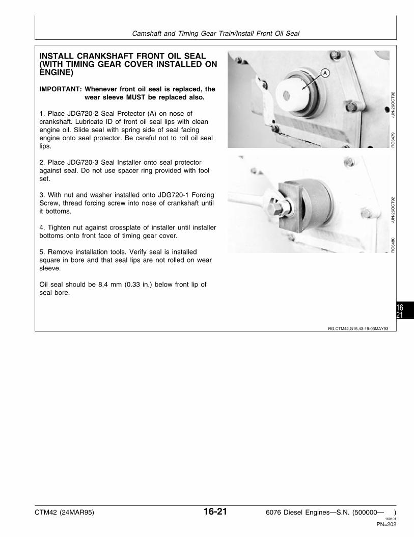
INSTALL CRANKSHAFT FRONT OIL SEAL(WITH TIMING GEAR COVER INSTALLED ONENGINE)
IMPORTANT: Whenever front oil seal is replaced, thewear sleeve MUST be replaced also.
1. Place JDG720-2 Seal Protector (A) on nose ofcrankshaft. Lubricate ID of front oil seal lips with cleanengine oil. Slide seal with spring side of seal facingengine onto seal protector. Be careful not to roll oil seallips.
2. Place JDG720-3 Seal Installer onto seal protectoragainst seal. Do not use spacer ring provided with toolset.
3. With nut and washer installed onto JDG720-1 ForcingScrew, thread forcing screw into nose of crankshaft untilit bottoms.
4. Tighten nut against crossplate of installer until installerbottoms onto front face of timing gear cover.
5. Remove installation tools. Verify seal is installedsquare in bore and that seal lips are not rolled on wearsleeve.
Oil seal should be 8.4 mm (0.33 in.) below front lip ofseal bore.
RG
6479
-U
N-2
6OC
T92
RG
6480
-U
N-2
6OC
T92
RG,CTM42,G15,43-19-03MAY93
Camshaft and Timing Gear Train/Install Front Oil Seal
CTM42 (24MAR95) 16-21 6076 Diesel Engines—S.N. (500000— )160101
PN=202
1621

COMPLETE FINAL ASSEMBLY
1. Install the magnetic pickup assembly in timing gearcover (if equipped). Tighten to 14 N·m (10 lb-ft).
2. Install injection pump drive gear cover and gasket.Tighten the six cap screws to 27 N·m (20 lb-ft).
3. Install vibration damper and pulley assembly. (SeeGroup 15, Crankshaft, Main Bearings and Flywheel.)
4. Install cylinder head, valve train, and rocker armassembly. (See Group 05, Cylinder Head and Valves.)
5. Install oil pan and new gasket. (See Group 20,Lubrication System.) Fill engine with clean engine oil.
6. Perform engine break-in as required. (See PERFORMENGINE BREAK-IN, Group 05.)
RG,CTM42,G16,29-19-24MAR95
Camshaft and Timing Gear Train/Complete Final Assembly
CTM42 (24MAR95) 16-22 6076 Diesel Engines—S.N. (500000— )160101
PN=203
1622

OTHER MATERIAL
Name Use
PERMATEX AVIATION (Form-A-Gasket No. 3) To seal gasket surfaces on oil pan.(TY6299)
LOCTITE 242 Thread Lock and Sealer Oil filter adapter threads(TY9370 or T43512)
LOCTITE 592 Pipe Sealant with TEFLON To seal oil pan elbow drain fitting.(TY9374/TY9375)
High Temperature Grease To lubricate oil pump components.(TY6343 or TY6347)
LUBRICATION SYSTEM SPECIFICATIONS
ITEM SPECIFICATION
Oil Filter Bypass Valve Operating Pressure . . . . . . 210 kPa (2.1 bar) (30 psi)
Oil Pressure Regulating Valve Spring: Compressed Length . . . . . . . . . . . . . . . . . . . . 43.0 mm @ 66—74 N (1.69 in. @ 15—17 lb-force) Free Length . . . . . . . . . . . . . . . . . . . . . . . . . . 85.0 mm (3.35 in.)
Oil Filter Bypass Valve Spring: Compressed Length . . . . . . . . . . . . . . . . . . . . 30.0 mm @ 64—78 N (1.18 in. @ 14—18 lb-force) Free Length . . . . . . . . . . . . . . . . . . . . . . . . . . 44.0 mm (1.73 in.)
Oil Cooler Bypass Valve Spring: Compressed Length . . . . . . . . . . . . . . . . . . . . 30.0 mm @ 64—78 N (1.18 in. @ 14—18 lb-force) Free Length . . . . . . . . . . . . . . . . . . . . . . . . . . 44.0 mm (1.73 in.)
Oil Pump: Crankshaft Gear-to-Oil Pump Drive Gear Minimum Backlash . . . . . . . . . . . . . . . . . . . . 0.08 mm (0.003 in.) Pump Gear Backlash . . . . . . . . . . . . . . . . . . . . 0.33—2.00 mm (0.013—0.079 in.) Oil Pump Drive Gear-to-Crankshaft Throw Minimum Clearance . . . . . . . . . . . . . . . . . . . 0.38 mm (0.015 in.) Maximum Drive Shaft End Play . . . . . . . . . . . . . 0.15 mm (0.006 in.) Maximum Drive Shaft Side Movement . . . . . . . . 0.17 mm (0.0065 in.)
RG,CTM42,G20,1 -19-16AUG94
RG,CTM42,G20,2 -19-07JUN93
Group 20Lubrication System
CTM42 (24MAR95) 20-1 6076 Diesel Engines—S.N. (500000— )160101
PN=204
201

LUBRICATION SYSTEM SPECIFICATIONS—CONTINUED
TORQUES
Oil Conditioning Housing-to-Cylinder Block: * Step 1 . . . . . . . . . . . . . . . . . . . . . . . . . . . . . . . . . . . . . . . . . . . . . . . . . . . . . . . . . 20 N·m (15 lb-ft) Step 2 . . . . . . . . . . . . . . . . . . . . . . . . . . . . . . . . . . . . . . . . . . . . . . . . . . . . . . . . . 37 N·m (27 lb-ft)
Oil Pump: Drive Gear-to-Pump Drive Shaft Nut . . . . . . . . . . . . . . . . . . . . . . . . . . . . . . . . . . . . . 54 N·m (40 lb-ft) Pump Cover-to-Housing . . . . . . . . . . . . . . . . . . . . . . . . . . . . . . . . . . . . . . . . . . . . . 41 N·m (30 lb-ft) Intake Tube-to-Cover . . . . . . . . . . . . . . . . . . . . . . . . . . . . . . . . . . . . . . . . . . . . . . . 41 N·m (30 lb-ft) Pump Housing-to-Cylinder Block . . . . . . . . . . . . . . . . . . . . . . . . . . . . . . . . . . . . . . . . 47 N·m (35 lb-ft)
Oil Pan: ** 3/8 in. Cap Screws . . . . . . . . . . . . . . . . . . . . . . . . . . . . . . . . . . . . . . . . . . . . . . . . 68 N·m (50 lb-ft) 1/2 in. Cap Screws . . . . . . . . . . . . . . . . . . . . . . . . . . . . . . . . . . . . . . . . . . . . . . 156 N·m (115 lb-ft)
Oil Pan Drain Plug: Aluminum Pans . . . . . . . . . . . . . . . . . . . . . . . . . . . . . . . . . . . . . . . . . . . . . . . . . . 102 N·m (75 lb-ft) Cast Iron Pans . . . . . . . . . . . . . . . . . . . . . . . . . . . . . . . . . . . . . . . . . . . . . . . . . . 47 N·m (35 Lb-ft)
* Refer to INSTALL OIL FILTER AND OIL CONDITIONING HOUSING,later in this group, for proper cap screw tightening sequence.
** Initially tighten all cap screws to 54 N·m (40 lb-ft), starting at rightrear corner of oil pan (facing toward flywheel end) and proceedcounterclockwise. Finish tightening cap screws to torques specifiedabove, using the same sequence and tighten all 3/8 in. cap screwsfirst.
DRAIN ENGINE OIL AND REMOVE OIL PAN
1. Drain engine coolant.
2. Disconnect turbocharger oil inlet line at turbochargeror oil conditioning housing. (See DISCONNECTTURBOCHARGER OIL INLET LINE, in Group 03.)
3. Drain engine oil.
4. Remove oil level sight gauge (if equipped).
5. Remove oil pan and discard gasket.
RG,CTM42,G20,32-19-16AUG94
S11,0404,C -19-04JUN93
Lubrication System/Drain Engine Oil and Remove Oil Pan
CTM42 (24MAR95) 20-2 6076 Diesel Engines—S.N. (500000— )160101
PN=205
202

OIL FILTER AND OIL CONDITIONING HOUSING ASSEMBLY
A—Gasket G—Spring L—Oil Filter Q—Oil Pressure RegulatingB—Oil Cooler H—Oil Cooler Bypass Valve M—Plug ValveC—Gasket I—Oil Conditioning Housing N—O-Ring R—SpringD—Fitting J—Cap Screw (10 Used) O—Spring S—O-RingE—Plug K—Adapter P—Oil FIlter Bypass Valve T—PlugF—O-Ring
RG
5896
-U
N-1
6AU
G91
RG,CTM42,G20,5 -19-09OCT92
Lubrication System/Oil Filter and Oil Conditioning Housing Assembly
CTM42 (24MAR95) 20-3 6076 Diesel Engines—S.N. (500000— )160101
PN=206
203

REMOVE OIL FILTER AND OILCONDITIONING HOUSING
1. Disconnect turbocharger oil inlet line (B) from oilconditioning housing (A).
2. Turn oil filter (C) counterclockwise and remove filterfrom housing.
3. Remove cap screws securing oil conditioning housingto cylinder block and remove housing.
RG
5897
-U
N-1
6AU
G91
INSPECT AND REPLACE OIL FILTERADAPTER
1. Inspect threads on oil filter adapter (B) for damage.Remove adapter from housing (A) if necessary.
2. Coat adapter-to-oil conditioner housing threads withLOCTITE 242 Thread Lock and Sealer before installingadapter in housing.
RG
7214
-U
N-0
7JU
L94
RG,CTM42,G20,6 -19-09OCT92
RG,CTM42,G20,41-19-16AUG94
Lubrication System/Inspect and Replace Oil Filter Adapter
CTM42 (24MAR95) 20-4 6076 Diesel Engines—S.N. (500000— )160101
PN=207
204

REMOVE, INSPECT, AND INSTALL OIL PRESSURE REGULATING VALVE, OIL FILTERBYPASS VALVE, AND OIL COOLER BYPASS VALVE
See OIL FILTER AND OIL CONDITIONINGHOUSING ASSEMBLY, earlier in this group, forillustration of valves.
• Oil Pressure Regulating Valve
1. Remove plug (T), O-ring (S), spring (R), oilpressure regulating valve (Q) from housing (I).Discard O-ring.
2. Inspect valve and valve bore for damage. Replaceif necessary.
3. Check spring for proper compression.
NEW PRESSURE REGULATING VALVE SPRING SPECIFICATION
Working Load at 66—74 N . . . . . . . . . . . . . . . . . . . . . 43.0 mm (15—17 lb force) (1.69 in.)
Spring Free Length . . . . . . . . . . . . . . . . . . . 85.0 mm (3.35 in.)
4. Dip all parts in clean engine oil, insert valve andspring in housing.
5. Install plug using a new O-ring and tightensecurely.
• Oil Filter Bypass Valve
1. Remove plug (M) with O-ring (N), spring (O), andoil filter bypass valve (P) from oil conditioning housing(I). Discard O-ring.
2. Inspect valve and housing bore for scoring ordamage. Replace if necessary.
3. Check spring for proper compression. Replace ifnecessary.
NEW OIL FILTER BYPASS VALVE SPRING SPECIFICATION
Working Load at 64—78 N . . . . . . . . . . . . . . . . . . . . . 30.0 mm (14—18 lb force) (1.18 in.)
Spring Free Length . . . . . . . . . . . . . . . . . . . 44.0 mm (1.73 in.)
4. Dip all parts in clean engine oil, insert valve andspring in housing.
5. Install new O-ring on plug. Install plug and tightensecurely.
NOTE: Filter bypass valve operating pressure is 210kPa (2.10 bar) (30 psi).
• Oil Cooler Bypass Valve
1. Remove plug (E), O-ring (F), spring (G), and oilcooler bypass valve (H) from oil conditioning housing(I). Discard O-ring.
2. Check housing for clogged passages and all otherparts for scale build-up.
3. Clean all parts with a stiff bristle brush andsolvent, if necessary. Dry with compressed air.
4. Inspect bypass valve for damage. Replace ifnecessary.
5. Check bypass valve spring for properspecifications. Replace if not within specifications.
NEW OIL COOLER BYPASS VALVE SPRING SPECIFICATION
Working Load at 64—78 N . . . . . . . . . . . . . . . . . 30.0 mm (14-18 lb force) (1.18 in.)
Spring Free Length . . . . . . . . . . . . . . . . . . . 44.0 mm (1.73 in.)
RG,CTM42,G20,29-19-12APR93
Lubrication System/Remove, Inspect, and Install Valves from Oil Conditioning Housing
CTM42 (24MAR95) 20-5 6076 Diesel Engines—S.N. (500000— )160101
PN=208
205

INSTALL OIL FILTER AND OIL CONDITIONING HOUSING
A—Oil Conditioning Housing C—Oil Cooler D—Gasket E—TabB—Gasket
1. Remove all gasket material from cylinder block andoil conditioning housing (A).
2. Install gasket (D), engine oil cooler (C), gasket (B),and oil conditioning housing onto cylinder block using5/16 x 3 in. studs. Tab (E) on gasket with siliconebead should be downward and to the right.
RG
5904
-U
N-2
0AU
G91
3. Tighten cap screws to 20 N·m (15 lb-ft) followingsequence shown in diagram.
4. Retighten cap screws to 37 N·m (27 lb-ft) followingsame sequence.
NOTE: It may be helpful to put an ink mark on each capscrew after tightening each time to assure all capscrews have been tightened.
RG
5905
-U
N-1
6AU
G91
RG,CTM42,G20,9 -19-09OCT92
RG,CTM42,G20,10-19-09OCT92
Lubrication System/Install Oil Filter and Oil Conditioning Housing
CTM42 (24MAR95) 20-6 6076 Diesel Engines—S.N. (500000— )160101
PN=209
206

REMOVE ENGINE OIL COOLER
6076 Engines are equipped with a 6-plate engine oilcooler.
1. Remove cover (A).
2. Remove oil cooler.
6-plate oil cooler
RG
5907
-U
N-1
6AU
G91
RG
5908
-U
N-1
6AU
G91
RG,CTM42,G20,25-19-09OCT92
Lubrication System/Remove Engine Oil Cooler
CTM42 (24MAR95) 20-7 6076 Diesel Engines—S.N. (500000— )160101
PN=210
207

CLEAN, INSPECT, AND INSTALL ENGINE OIL COOLER
A—Oil Conditioning Housing B—Gasket C—Oil Cooler D—Gasket
1. Once oil cooler is removed, scrape off all oldgasket material from cooler and block.
2. Clean all parts with clean solvent and a brass wirebrush. Dry with compressed air.
3. Inspect all parts for serviceability. Replace parts asnecessary.
NOTE: If mixing of oil and coolant is suspected,pressure test oil cooler in liquid andcompressed air. Use 140—170 kPa (1.4—1.7bar) (20—25 psi) air pressure for testing.Replace oil cooler as necessary.
4. Using new gaskets install oil cooler/oil conditioninghousing. See INSTALL OIL FILTER AND OILCONDITIONING HOUSING, earlier in this group.
RG
5904
-U
N-2
0AU
G91
RG,CTM42,G20,12-19-09OCT92
Lubrication System/Clean, Inspect, and Install Engine Oil Cooler
CTM42 (24MAR95) 20-8 6076 Diesel Engines—S.N. (500000— )160101
PN=211
208

CHECK CRANKSHAFT GEAR-TO-OIL PUMPDRIVE GEAR BACKLASH
Before removing oil pump, determine if there is adequatebacklash between oil pump and crankshaft drive gears.
1. Mount dial indicator (A) and measure backlashbetween pump drive gear (B) and crankshaft gear (C).
IMPORTANT: Backlash must be at least 0.08 mm(0.003 in.). If backlash is less than 0.08mm (0.003 in.), replace the oil pumpdrive gear.
RG
5914
-U
N-1
6AU
G91
REMOVE ENGINE OIL PUMP
1. Remove four oil pump housing cap screws (A).
2. Remove oil pump assembly with drive gear (B)attached.
RG
5915
-U
N-1
6AU
G91
RG,CTM42,G20,16-19-09OCT92
RG,CTM42,G20,17-19-09OCT92
Lubrication System/Remove Engine Oil Pump
CTM42 (24MAR95) 20-9 6076 Diesel Engines—S.N. (500000— )160101
PN=212
209

INSPECT AND CLEAN OIL PUMP
1. Visually inspect oil pump for wear or damage.
IMPORTANT: DO NOT disassemble engine oil pumpfor flushing, inspection, or performingwear checks. Individual components ofoil pump are not available throughsevice parts, Replace pump as acomplete assembly.
2. Flush pump assembly internally with clean solvent toremove oil. Spin pump gears to help remove solvent.
3. Place oil pump on a work bench with pump-to-cylinderblock mounting surface facing upward (same as whenmounted on engine).
NOTE: Leave pump drive gear installed when makingchecks.
IMPORTANT: To help insure accurate wearmeasurements, be sure the oil pump isclean and faces the same way as whenmounted on the cylinder block.
RG,CTM42,G20,18-19-15SEP94
Lubrication System/Inspect and Clean Oil Pump
CTM42 (24MAR95) 20-10 6076 Diesel Engines—S.N. (500000— )160101
PN=213
2010

CHECK DRIVE SHAFT END PLAY
1. Mount dial indicator with indicator plunger restingagainst end of pump drive shaft.
2. Move shaft toward and away from indicator.
If end play exceeds 0.15 mm (0.006 in.), there isexcessive wear on pump cover and/or wear on end ofpump drive gear.
Replace oil pump if end play exceeds 0.15 mm (0.006in.).
RG
5916
-U
N-1
6AU
G91
CHECK DRIVE SHAFT SIDE MOVEMENT
1. Mount dial indicator with indicator plunger resting onone of the hex nut flats.
2. Move shaft from side-to-side.
If shaft side movement exceeds 0.17 mm (0.0065 in.),there is excessive wear on drive shaft bushing and/ordrive shaft.
Replace oil pump if shaft side movement exceeds 0.17mm (0.0065 in.).
RG
5917
-U
N-1
6AU
G91
RG,CTM42,G20,19-19-09OCT92
RG,CTM42,G20,20-19-09OCT92
Lubrication System/Check Drive Shaft Side Movement
CTM42 (24MAR95) 20-11 6076 Diesel Engines—S.N. (500000— )160101
PN=214
2011

CHECK PUMPING GEAR BACKLASH
1. Mount dial indicator with indicator plunger restingagainst side of gear tooth.
2. Hold idler gear stationary. Slowly rotate drive gearback and forth until contact with idler gear is felt.
If backlash is not within 0.33—2.00 mm (0.013—0.079in.) specification, there is excessive pumping gear wearand/or idler shaft and gear bushing wear. If there is lessthan 0.33 mm (0.013 in.) backlash, re-clean gears andcheck backlash again.
3. Replace oil pump if pumping gear backlash exceeds2.00 mm (0.079 in.).
RG
5918
-U
N-1
6AU
G91
INSPECT OIL PUMP DRIVE GEAR
NOTE: Oil pump does not need to be removed fromengine, when inspecting drive gear.
1. Inspect drive gear teeth for chips, cracks, or wear.Replace as necessary.
RG
6435
-U
N-1
3OC
T92
RG,CTM42,G20,21-19-16AUG94
RG,CTM42,G20,31-19-09OCT92
Lubrication System/Inspect Oil Pump Drive Gear
CTM42 (24MAR95) 20-12 6076 Diesel Engines—S.N. (500000— )160101
PN=215
2012

INSTALL ENGINE OIL PUMP
1. Lubricate bottom surface of oil pump housing gearpocket bores, idler shaft, gear teeth on drive shaft, andoil pump cover ends of both gears with TY6333 orTY6347 High Temperature Grease.
2. Tighten oil pump drive gear-to-drive shaft nut (A) to54 N·m (40 lb-ft). Install oil pump cover (B)-to-oil pumphousing (C).
3. Using a new gasket, install oil pump intake (F)-to-oilpump cover and tighten cap screws to 41 N·m (30 lb-ft).
NOTE: Oil pump gears must turn freely after installationof oil pump cover and intake.
4. Install oil pump assembly over hollow dowel pin incylinder block. Tighten oil pump housing-to-cylinder blockcap screws to 47 N·m (35 lb-ft).
A—Shaft NutNOTE: Make sure oil pump drive gear (D) meshes B—Oil Pump Cover
properly with crankshaft gear (E). C—Oil Pump HousingD—Oil Pump Drive GearE—Crankshaft GearF—Oil Pump Intake
RG
5922
-U
N-1
6AU
G91
IMPORTANT: Push crankshaft rearward (towardflywheel end). Check clearance betweenoil pump drive gear face and throw ofcrankshaft. There should be aclearance of at least 0.38 mm (0.0015in.). If clearance is below specification,check thrust bearings for properplacement. Gently pry crankshaftforward and check (after oil pump isinstalled) the oil pump drive gear (A),and crankshaft gear (B) to see that theyare properly meshed.
RG
5923
-U
N-2
0AU
G91
RG,CTM42,G20,23-19-16AUG94
RG,CTM42,G20,24-19-22AUG91
Lubrication System/Install Engine Oil Pump
CTM42 (24MAR95) 20-13 6076 Diesel Engines—S.N. (500000— )160101
PN=216
2013

INSTALL OIL PAN
Before installing oil pan, remove old gasket and sealantmaterial from pan and cylinder block mating surfaces.Guide studs may be used if desired.
1. Apply a thin layer of PERMATEX AVIATION(Form-A-Gasket No. 3) across entire front and reargasket rail of block. Install gasket (A) onto cylinder blockand apply a layer of sealant to gasket across front andrear gasket face. On engines equipped with multi-piecegaskets, also apply sealant to mating joints. Install oilpan.
2. Insert all 3/8 in. and 1/2 in. cap screws in theirappropriate locations.
3. Use a straightedge against oil pan and cylinder block(flywheel end) to be sure oil pan is flush with blockflange.
4. Proceeding counterclockwise (bold arrows) fromflywheel end (B), tighten all cap screws to 47 N·m (35lb-ft).
5. Repeat sequence by tightening all 3/8 in. cap screwsto 68 N·m (50 lb-ft).
6. Complete sequence by tightening counterclockwise all1/2 in. cap screws to 156 N·m (115 lb-ft). Check torqueon all 3/8 in. cap screws after final torque of 1/2 in. capscrews. Trim gasket flush with rear of pan flange.
7. Bottom oil pan drain plug (D) uses either an aluminumwasher or rubber O-ring (C) for sealing. Apply a lightcoat of engine oil to new rubber O-rings for bottom drainplug. Install aluminum washer on drain plug so raisedcenter contacts head of plug.
Some engine oil pans may be equipped with an elbowfitting (E) and drain hose (F).
8. Install drain plug and tighten to specifications listedbelow. Fill engine crankcase with correct engine oil.
A—Oil Pan GasketOIL PAN DRAIN PLUG TORQUE SPECIFICATIONSB—Location For First Cap ScrewAluminum Oil Pans . . . . . . . . . . . . . . . . . . . . . . 102 N·m (75 lb-ft)C—O-Ring or Aluminum WasherCast Iron Oil Pans . . . . . . . . . . . . . . . . . . . . . . . 47 N·m (35 lb-ft)D—Drain PlugE—Elbow Fitting
NOTE: On engine equipped with elbow fittings and drain F—Drain Hosehose, the threads and sealing surfaces must befree of any oil film to insure an effective seal.Apply a light coat of LOCTITE 592 to fittingsexcept for the leading one to three threads.Tighten fittings securely.
RG
5267
-U
N-2
9NO
V88
RG
5010
-U
N-2
9NO
V88
S55,2020,O -19-16AUG94
Lubrication System/Install Oil Pan
CTM42 (24MAR95) 20-14 6076 Diesel Engines—S.N. (500000— )160101
PN=217
2014

TIGHTEN CAP SCREWS ON FRONT FRAME/OIL SUMP
A—0.375 x 7.625 in. (2 used) C—0.500 x 6.000 in. (8 used) E—0.500 x 2.500 in. (6 used) F—0.375 x 1.875 in. (2 used)B—0.500 x 4.000 in. (4 used) D—0.375 x 2.500 in. (2 used)
1. Be sure dowel pins are in place.
IMPORTANT: DO NOT apply gasket sealant togasket, front frame/oil sump,trimmed edges of timing gear covergasket, oil seal housing gasket, orcylinder block mating surfaces.Before installing engine, be suremating surfaces of engine and frontframe/oil sump are clean.
2. Install front frame/oil sump-to-cylinder block gasket.
3. Carefully lower engine onto front frame/oil sump.
4. Install all 3/8 in. and 1/2 in. cap screws in theirappropriate locations.
5. Tighten all 1/2 in. cap screws to 133 N·m (98 lb-ft).Tighten all 3/8 in. cap screws to 58 N·m (43 lb-ft).
6. Re-tighten all 3/8 in. cap screws to 58 N·m (43lb-ft). Re-tighten all 1/2 in. cap screws to 133 N·m(98 lb-ft).
7. Apply clean engine oil to new O-ring for bottomdrain plug and install drain plug.
RG
7223
-U
N-2
1JU
N94
RG,CTM42,G20,33-19-17MAR95
Lubrication System/Tighten cap screws on front frame/oil sump
CTM42 (24MAR95) 20-15 6076 Diesel Engines—S.N. (500000— )160101
PN=218
2015

Lubrication System/Tighten cap screws on front frame/oil sump
CTM42 (24MAR95) 20-16 6076 Diesel Engines—S.N. (500000— )160101
PN=219
2016

SPECIAL OR ESSENTIAL TOOLS
NOTE: Order tools according to information given in theU.S. SERVICE-GARD™ Catalog or in theEuropean Microfiche Tool Catalog (MTC).
Push Puller . . . . . . . . . . . . . . . . . . . . . . D01206AA
Used to remove water pump impeller from water pumpand to remove fan pulley from shaft pressed into watermanifold. Also used with D01217AA to remove waterpump drive gear from water pump.
RG
5097
-U
N-2
3AU
G88
Bearing Puller* . . . . . . . . . . . . . . . . . . . . D01217AA
Used with D01206AA to remove water pump drive gearfrom water pump.
* Part of D01212AA Step Plate Adapter Set
RG
4981
-U
N-0
6AP
R89
Belt Tension Gauge . . . . . . . . . . . . . . . . . . JDG529
Used to check and adjust fan belt tension.
RG
5082
-U
N-2
3AU
G88
Belt Tension Gauge . . . . . . . . . . . . . . . . . . JDST28
Used with a straightedge to check fan belt tension.
RG5588 -UN-13SEP89
DX,TOOLS -19-05JUN91
RG,CTM42,G25,33-19-10SEP91
RG,CTM42,G25,34-19-10SEP91
S53,JDG529 -19-06APR94
RG,CTM61,G25,26-19-17MAR92
Group 25Cooling System
CTM42 (24MAR95) 25-1 6076 Diesel Engines—S.N. (500000— )160101
PN=220
251

Bearing Driver . . . . . . . . . . . . . . . . . . . . . . JDG727
Used to remove and install water pump bearingassembly in water pump housing. Installs new bearing tothe correct depth.
RG
5963
-U
N-0
3SE
P91
OTHER MATERIAL
Name Use
LOCTITE 518 (TY6304) Flexible Sealant Water pump, thermostat cover and watermanifold gaskets.
LOCTITE 242 (TY9370) Thread Lock and Sealer Water outlet manifold-to-cylinder head cap screws.
LOCTITE 592 (TY9375) Pipe Sealant with TEFLON Water pump and block drain valves.
High Temperature Grease Pack bearings in fan drive.(TY6333 or TY6347)
RG,CTM42,G25,35-19-10SEP91
RG,CTM42,G25,7 -19-16AUG94
Cooling System/Other Material
CTM42 (24MAR95) 25-2 6076 Diesel Engines—S.N. (500000— )160101
PN=221
252

COOLING SYSTEM SPECIFICATIONS
ITEM SPECIFICATION
Water Pump: Impeller Bore ID . . . . . . . . . . . . . . . . . . . . . . . . . . . . . . . . . . . . . 15.849—15.875 mm (0.624—0.625 in.) Shaft OD Impeller End . . . . . . . . . . . . . . . . . . . . . . . . . . . . . . . . . 15.905—15.917 mm (0.626—0.627 in.) Bearing Bore in Water Pump Housing (NEW) . . . . . . . . . . . . . . . . . . 38.041—38.067 mm (1.498—1.499 in.) Maximum Allowable Pump Bearing Bore . . . . . . . . . . . . . . . . . . . . . . . . . . . . . . . . . 38.067 mm (1.499 in) Bearing OD . . . . . . . . . . . . . . . . . . . . . . . . . . . . . . . . . . . . . . . . 38.087—38.100 mm (1.499—1.500 in.) Drive Gear Bore ID . . . . . . . . . . . . . . . . . . . . . . . . . . . . . . . . . . . . . 18.90—18.92 mm (0.744—0.745 in.) Shaft OD Drive Gear End . . . . . . . . . . . . . . . . . . . . . . . . . . . . . . . 18.948—18.960 mm (0.746—0.747 in.) Water Pump Seal Installed Height . . . . . . . . . . . . . . . . . . . . . . . . . . . 10.16—10.42 mm (0.400—0.410 in.) Impeller Installed Depth Below Gasket Surface . . . . . . . . . . . . . . . . . . . . . 2.75—3.50 mm (0.108—0.138 in.) Bearing Installed Depth Below Pump Housing Nose . . . . . . . . . . . . . . . . . 6.75—7.00 mm (0.266—0.276 in.)
Thermostat Opening Temperature: 82˚C (180˚F) Thermostat(s) . . . . . . . . . . . . . . . . . . . . . . . . . . . . . . . . . . . . . . . . . 80—84˚C (175—182˚F) 89˚C (192˚F) Thermostat(s) . . . . . . . . . . . . . . . . . . . . . . . . . . . . . . . . . . . . . . . . . 87—91˚C (188—195˚F)
Heavy Duty Adjustable Fan Drive*: Bearing Bore ID in Housing . . . . . . . . . . . . . . . . . . . . . . . . . . . . 71.999—72.025 mm (2.8346—2.8356 in.) Shaft OD for Bearings . . . . . . . . . . . . . . . . . . . . . . . . . . . . . . . . 35.001—35.017 mm (1.3780—1.3786 in.) Bearing OD . . . . . . . . . . . . . . . . . . . . . . . . . . . . . . . . . . . . . . . 71.987—72.013 mm (2.8341—2.8351 in.) Bearing ID . . . . . . . . . . . . . . . . . . . . . . . . . . . . . . . . . . . . . . . . 34.987—35.013 mm (1.3774—1.3785 in.) Maximum Shaft End Play . . . . . . . . . . . . . . . . . . . . . . . . . . . . . . . . . . . . . . . . . . . . 0.50 mm (0.020 in.)
Standard Duty Adjustable Fan Drive*: Bearing Bore ID in Housing . . . . . . . . . . . . . . . . . . . . . . . . . . . . 47.576—47.612 mm (1.8731—1.8745 in.) Bearing OD (Housing End) . . . . . . . . . . . . . . . . . . . . . . . . . . . . . 47.612—47.625 mm (1.8745—1.8750 in.) Shaft OD (Pulley End) . . . . . . . . . . . . . . . . . . . . . . . . . . . . . . . . 25.387—25.400 mm (0.9995—1.0000 in.) Fan Pulley Bore ID . . . . . . . . . . . . . . . . . . . . . . . . . . . . . . . . . . 25.336—25.362 mm (0.9975—0.9985 in.) Bearing/Shaft Installed Dim. From Pulley Front Face . . . . . . . . . . . . . . . . Flush to 1.30 mm (0.05 in.) Below
Water Manifold Mounted, Fixed Fan Drive*: Shaft Installed Dimension From Manifold Mounting Face-to-End of Shaft . . . . . . . . . . . . . . . . . . . . . . . . . . . . . 33.31—33.57 mm (1.311—1.322 in.) Fan Pulley Bore ID . . . . . . . . . . . . . . . . . . . . . . . . . . . . . . . . . . 47.576—47.612 mm (1.8731—1.8745 in.) Bearing OD (Pulley End) . . . . . . . . . . . . . . . . . . . . . . . . . . . . . . 47.612—47.625 mm (1.8745—1.8750 in.) Shaft OD (Manifold End) . . . . . . . . . . . . . . . . . . . . . . . . . . . . . . 25.387—25.400 mm (0.9995—1.0000 in.) Manifold Bore ID . . . . . . . . . . . . . . . . . . . . . . . . . . . . . . . . . . . . 25.336—25.362 mm (0.9975—0.9985 in.)
Injection Pump Drive Gear Cover Mounted, Fan Pulley: Bearing OD (Pulley End) . . . . . . . . . . . . . . . . . . . . . . . . . . . . . . 47.612—47.625 mm (1.8745—1.8750 in.) Bearing OD (Drive Gear Cover End) . . . . . . . . . . . . . . . . . . . . . . . 25.387—25.400 mm (0.9995—1.0000 in.) Fan Pulley Bore ID . . . . . . . . . . . . . . . . . . . . . . . . . . . . . . . . . . 47.576—47.612 mm (1.8731—1.8745 in.) Drive Gear Cover ID . . . . . . . . . . . . . . . . . . . . . . . . . . . . . . . . . 25.336—25.362 mm (0.9975—0.9985 in.) Shaft Installed Dimension Injection Pump Drive Gear Cover Mounting Face-to-End of Shaft . . . . . . . . 3.43—3.69 mm (0.135—0.145 in.)
* Specifications apply only to fan drives supplied by John DeereFactory. Refer to manufacturers specifications for other fan drives. RG,CTM42,G25,1 -19-17MAR95
Cooling System/Cooling System Specifications
CTM42 (24MAR95) 25-3 6076 Diesel Engines—S.N. (500000— )160101
PN=222
253

COOLING SYSTEM SPECIFICATIONS—CONTINUED
ITEM SPECIFICATION
Standard V-Belt Tension Using JDG529 Gauge: Single Belt System: New Belts . . . . . . . . . . . . . . . . . . . . . . . . . . . . . . . . . . . . . . . . . . . . . . . . . . 578—622 N (130—140 lb) Belts in Service (minimum 10-minutes use) . . . . . . . . . . . . . . . . . . . . . . . . . . . . 378—423 N (85—95 lb) Dual Belt System*: New Belts . . . . . . . . . . . . . . . . . . . . . . . . . . . . . . . . . . . . . . . . . . . . . . . . . . . 422—463 N (95—104 lb) Belts in Service (minimum 10-minutes use) . . . . . . . . . . . . . . . . . . . . . . . . . . . . 378—423 N (85—95 lb)
Poly V-Belt Tension Using JT05975 Gauge: New Belts . . . . . . . . . . . . . . . . . . . . . . . . . . . . . . . . . . . . . . . . . . . . . . . . . 890—1068 N (200—240 lb) Belt in Service (minimum 10-minutes use) . . . . . . . . . . . . . . . . . . . . . . . . . . . . . 800—979 N (180—220 lb)
Fan Belt Tension Using JDST28 Tension Gauge and Straight Edge:(force applied halfway between pulleys) Standard V-Belts (new and used) . . . . . . . . . . . . . . . . . . . . . . . . . 19 mm (3/4 in.) with 89 N (20 lb) force Poly V-Belts (new and used) . . . . . . . . . . . . . . . . . . . . . . . . . . . 13 mm (1/2 in.) with 130 N (30 lb) force
* On engines with dual belts, check tension on front belt only. Measuretension on long part of belt. RG,CTM42,G25,41-19-29OCT92
Cooling System/Cooling System Specifications
CTM42 (24MAR95) 25-4 6076 Diesel Engines—S.N. (500000— )160101
PN=223
254

COOLING SYSTEM SPECIFICATIONS—CONTINUED
TORQUES
Water Pump-to-Cylinder Block Cap Screw . . . . . . . . . . . . . . . . . . . . . . . . . . . . . . . . . . . . 27 N·m (20 lb-ft)
Water Manifold-to-Cylinder Head—Cast Iron . . . . . . . . . . . . . . . . . . . . . . . . . . . . . . . . . . 61 N·m (45 lb-ft) —Aluminum . . . . . . . . . . . . . . . . . . . . . . . . . . . . . . . . . . 20 N·m (15 lb-ft)
Thermostat Cover-to-Water Manifold—Cast Iron . . . . . . . . . . . . . . . . . . . . . . . . . . . . . . . . 47 N·m (35 lb-ft) —Aluminum . . . . . . . . . . . . . . . . . . . . . . . . . . . . . . . 20 N·m (15 lb-ft)
Water Pump Cover-to-Water Pump Housing . . . . . . . . . . . . . . . . . . . . . . . . . . . . . . . . . . 30 N·m (22 lb-ft)
Water Pump Drain Valve-to-Water Pump Cover . . . . . . . . . . . . . . . . . . . . . . . . . . . . . . . . 27 N·m (20 lb-ft)
Water Inlet Manifold Elbow-to-Cylinder Block . . . . . . . . . . . . . . . . . . . . . . . . . . . . . . . . . . 30 N·m (22 lb-ft)
Fan-to-Fan Hub or Pulley* . . . . . . . . . . . . . . . . . . . . . . . . . . . . . . . . . . . . . . . . . . . . . . 40 N·m (30 lb-ft)
Fan Drive Assembly-to-Support Plate (Heavy Duty Adjustable Fan Drive) . . . . . . . . . . . . . . . 80 N·m (60 lb-ft)
Fan Spacer and Pulley-to-Hub . . . . . . . . . . . . . . . . . . . . . . . . . . . . . . . . . . . . . . . . . . . 47 N·m (35 lb-ft)
Fan Pulley Mounted Injection Pump Drive Gear Cover . . . . . . . . . . . . . . . . . . . . . . . . . . . 27 N·m (20 lb-ft)
* Applies only to fans provided by the John Deere factory. Seeequipment manufacturers recommendations for torque specifications onOEM supplied fans.
SERVICE EQUIPMENT AND TOOLS
NOTE: Order tools from your SERVICE-GARD™Catalog. Some tools may be available from alocal supplier.
Name Use
D01045AA Bushing, Bearing and Seal Driver Set Remove and install seals.
D01217AA Bearing Pulling Attachment Support gear during removal.
D01206AA Gear and Pulley Puller Remove gear from water pump shaft.
RG,CTM42,G25,2 -19-17MAR95
RG,CTM42,G25,38-19-06APR94
Cooling System/Service Equipment and Tools
CTM42 (24MAR95) 25-5 6076 Diesel Engines—S.N. (500000— )160101
PN=224
255

REPLACE BEARINGS IN STANDARD DUTY, ADJUSTABLE FAN DRIVE ASSEMBLY
A—Fan Hub/Pulley B—Bearing Housing C—Bearing/Shaft D—Support Plate
• To Disassemble Fan Drive:
1. Remove V-belt and remove support plate (D) withfan drive assembly.
2. Remove fan drive assembly from support plate.
3. Support back side of fan hub/pulley (A), and pressbearing/shaft (C) out of hub bore.
4. Support back side of bearing housing (B) andpress bearing/shaft out of housing. Discard bearing.
5. Thoroughly clean and inspect fan hub/pulley andbearing housing for cracks or any other damage.Measure parts and compare with specifications givenlater.
STANDARD DUTY, ADJUSTABLE FAN DRIVE SPECIFICATIONS
Housing ID . . . . . . . . . 47.576—47.612 mm (1.8731—1.8745 in.)
Bearing OD . . . . . . . . 47.612—47.625 mm (1.8745—1.8750 in.)
Shaft OD . . . . . . . . . . 25.387—25.400 mm (0.9954—1.0000 in.)
Pulley ID . . . . . . . . . . 25.336—25.362 mm (0.9975—0.9985 in.)
Shaft Installed Dimension From Pulley Front Face . . . . . . . . . . . . Flush to 1.30 mm (0.05 in.) Below
Replace parts that are cracked or not withinspecification.
RG
7305
-U
N-1
3MA
R95
RG,CTM42,G25,44-19-21MAR95
Cooling System/Replace Bearings in Standard Duty, Adjustable Fan Drive Assembly
CTM42 (24MAR95) 25-6 6076 Diesel Engines—S.N. (500000— )160101
PN=225
256
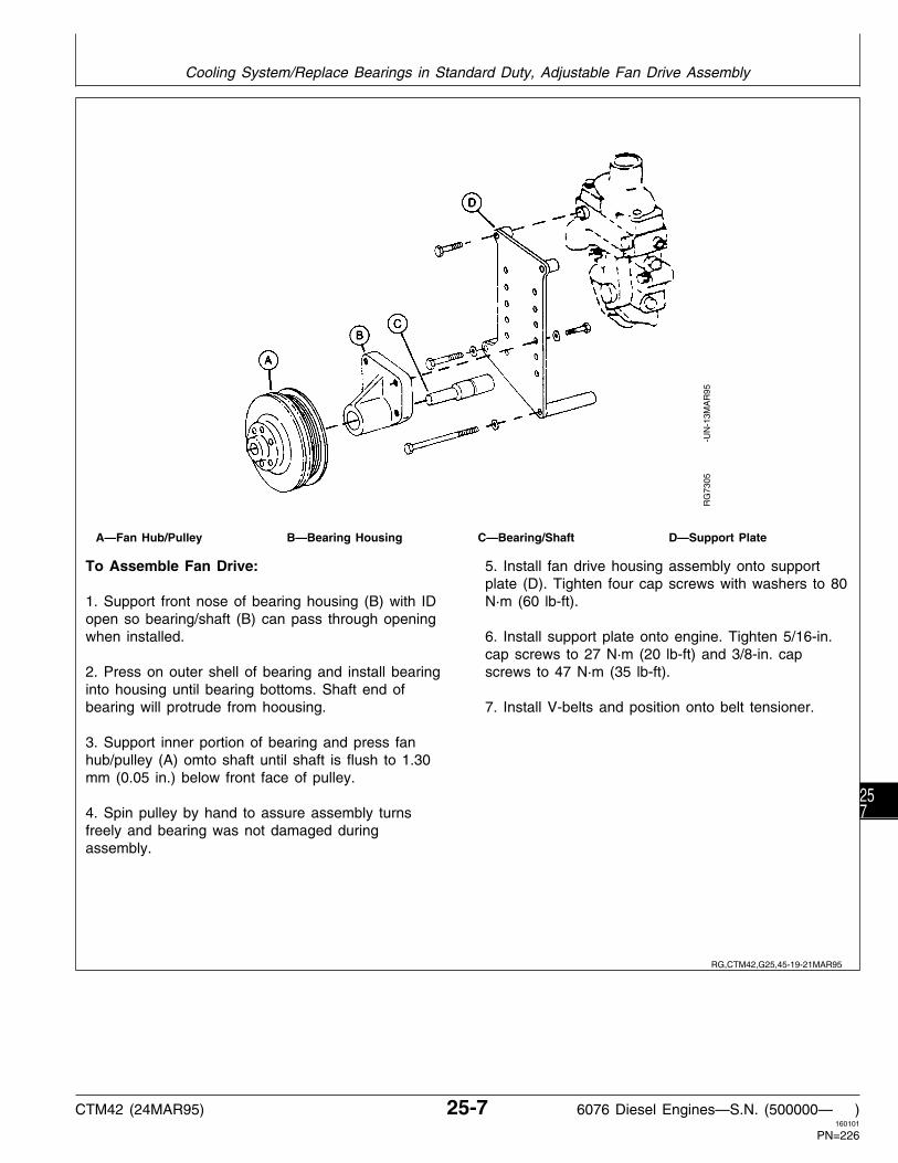
A—Fan Hub/Pulley B—Bearing Housing C—Bearing/Shaft D—Support Plate
To Assemble Fan Drive:
1. Support front nose of bearing housing (B) with IDopen so bearing/shaft (B) can pass through openingwhen installed.
2. Press on outer shell of bearing and install bearinginto housing until bearing bottoms. Shaft end ofbearing will protrude from hoousing.
3. Support inner portion of bearing and press fanhub/pulley (A) omto shaft until shaft is flush to 1.30mm (0.05 in.) below front face of pulley.
4. Spin pulley by hand to assure assembly turnsfreely and bearing was not damaged duringassembly.
5. Install fan drive housing assembly onto supportplate (D). Tighten four cap screws with washers to 80N·m (60 lb-ft).
6. Install support plate onto engine. Tighten 5/16-in.cap screws to 27 N·m (20 lb-ft) and 3/8-in. capscrews to 47 N·m (35 lb-ft).
7. Install V-belts and position onto belt tensioner.R
G73
05
-
UN
-13M
AR
95
RG,CTM42,G25,45-19-21MAR95
Cooling System/Replace Bearings in Standard Duty, Adjustable Fan Drive Assembly
CTM42 (24MAR95) 25-7 6076 Diesel Engines—S.N. (500000— )160101
PN=226
257

REPLACE BEARINGS IN HEAVY DUTY, ADJUSTABLE FAN DRIVE ASSEMBLY
A—Fan Hub/Pulley D—Ball Bearing (2 used) F—Bearing Housing H—Support SpacerB—Grease Seal E—Shaft G—Pipe Plug J—Support PlateC—Snap Ring
• To Disassemble Fan Drive:
1. Remove V-belts and remove fan. Remove fandrive assembly from engine.
2. Clamp fan hub/pulley (A) in a soft-jawed vise.Support fan hub (so it does not fall to floor), andremove cap screw securing hub to shaft (E). Removefan hub.
3. Remove pipe plug (G), grease seal (B), and snapring (C). Discard seal and snap ring.
4. Remove shaft with bearings (D) by lightly tappingwith a rubber mallet or brass hammer.
5. Remove bearings from shaft using a press anddiscard bearings.
6. Thoroughly clean and inspect shaft and bearinghousing (F) for cracks or any other damage. Measureparts and compare with specifications given below.
HEAVY DUTY, ADJUSTABLE FAN DRIVE SPECIFICATIONS
Housing ID . . . . . . . . . 71.999—72.025 mm (2.8346—2.8356 in.)
Shaft OD . . . . . . . . . . 35.001—35.017 mm (1.3780—1.3786 in.)
Bearing ID . . . . . . . . . 34.987—35.013 mm (1.3774—1.3785 in.)
Bearing OD . . . . . . . . 71.987—72.013 mm (2.8341—2.8351 in.)
Replace parts that are cracked or not withinspecification.
RG
5760
-U
N-0
6AU
G91
RG,CTM42,G25,9 -19-24MAR95
Cooling System/Replace Bearings in Heavy Duty, Adjustable Fan Drive Assembly
CTM42 (24MAR95) 25-8 6076 Diesel Engines—S.N. (500000— )160101
PN=227
258

A—Fan Hub/Pulley D—Ball Bearing (2 used) F—Bearing Housing H—Support SpacerB—Grease Seal E—Shaft G—Pipe Plug J—Support PlateC—Snap Ring
• To Assemble Fan Drive:
1. Pack inner and outer bearings (D) with TY6333 orTY6347 High Temperature Grease. Apply cleanengine oil to bearing ID and shaft OD.
2. Support end of shaft (E) and install bearingsagainst shoulder. Apply force to bearing inner raceonly.
3. Support bearing housing (F) on a firm flat surfacewith bearing bore in the upward position.
4. Install bearing and shaft assembly into housing.Small end of shaft should extend through housing.
5. Determine proper snap ring (C) thickness neededto obtain 0.10 mm (0.004 in.) end play.
6. Install snap ring in housing groove. Visually inspectsnap ring installation for proper seating in housinggroove.
7. Apply a thin coat of clean engine oil to OD of sealcasing (B) and to seal lips. Install seal in housingbore until metal casing is flush-to-0.50 mm (0.020 in.)below housing face.
8. Apply clean engine oil to ID of fan hub/pulley (A).Support end of shaft through pipe plug hole inbearing housing and push hub onto other end ofshaft until it bottoms against shoulder.
9. Install washer and cap screw. Tighten cap screwto 80 N·m (60 lb-ft).
10. Apply LOCTITE 592 Pipe Sealant to threads ofpipe plug (G). Install and tighten plug in bearinghousing.
11. Install fan drive assembly onto support plate (J).
12. Install support plate assembly onto engine andtighten 5/16-in mounting cap screws to 27 N·m (20lb-ft) and all 3/8-in. cap screws to 47 N·m (35 lb-ft).
RG
5760
-U
N-0
6AU
G91
RG,CTM42,G25,3 -19-17MAR95
Cooling System/Replace Bearings in Heavy Duty, Adjustable Fan Drive Assembly
CTM42 (24MAR95) 25-9 6076 Diesel Engines—S.N. (500000— )160101
PN=228
259

REPLACE BEARINGS IN WATER MANIFOLD MOUNTED, FIXED FAN DRIVE ASSEMBLY
A—Water Manifold C—Bearing E—Hub*B—Fan Pulley D—Bearing Shaft Installed
Dimension
• To Disassemble Fan Drive:
1. Remove three water manifold-to-cylinder head capscrews. Remove water manifold (A) and fan pulley(B) assembly from cylinder head and lift to dislodgewater bypass pipe from manifold.
2. Support front face of water manifold and use apress to push bearing (C) and pulley out of manifold.
3. Support front face of fan pulley and push bearingout of pulley, and fan spacer (if equipped). Discardbearing.
4. Thoroughly inspect water manifold and pulley forcracks or damage. Measure parts and comparereadings with specifications given below. Replaceparts as necessary.
IMPORTANT: Support fan pulley on a flat, firmsurface and press on bearing outerrace to prevent damage to thebearing.
5. Install new bearing into pulley until outer racebottoms in bore of pulley. End of shaft will extendthrough bearing stop.
WATER MANIFOLD MOUNTED, FIXED FAN DRIVESPECIFICATIONS
Shaft OD . . . . . . . . . . . . . . . . . . . . . . . . . 25.387—25.400 mm(0.9995—1.0000 in.)
Bearing OD . . . . . . . . . . . . . . . . . . . . . . . 47.612—47.625 mm(1.8745—1.8750 in.)
Pulley ID, Bearing End . . . . . . . . . . . . . . . . 47.576—47.612 mm(1.8731—1.8745 in.)
Pulley ID, Fan Spacer End** . . . . . . . . . . . . 49.485—49.518 mm(1.9482—1.9495 in.)
Fan Spacer OD** . . . . . . . . . . . . . . . . . . . 49.457—49.483 mm(1.9471—1.9481 in.)
Manifold ID . . . . . . . . . . . . . . . . . . . . . . . . 25.336—25.362 mm(0.9975—0.9985 in.)
Shaft Installed Dimension from Manifold Mounting Face-to-End of Shaft . . . . . . . . . . 33.31—33.47 mm
(1.311—1.318 in.)
*In some applications, bearing is pressed into hub (E). The fan spacerand pulley are then bolted to hub. In some applications, the fan spaceris press-fit into the pulley. Dimension (D) is the same for allapplications.
**Units with press-fit fan spacer only.
RG
6437
-U
N-1
3OC
T92
RG,CTM42,G25,10-19-14FEB95
Cooling System/Water Manifold Mounted Fixed Fan Drive Assembly
CTM42 (24MAR95) 25-10 6076 Diesel Engines—S.N. (500000— )160101
PN=229
2510

A—Water Manifold C—Bearing E—Hub*B—Fan Pulley D—Bearing Shaft Installed
Dimension
• To Assemble Fan Drive:
IMPORTANT:Support water manifold on machinedsurface and press on inner shaft toprevent damage to bearing.
1. On units with a press-fit fan spacer, press spacerinto pulley flush to 0.5 mm (0.020 in.) below frontface of pulley.
2. Press bearing shaft (C) into water manifold (A).End of shaft should be 33.31—33.47 mm
(1.311—1.318 in.) (D) from manifold mountingsurface. Hold water manifold firmly and turn fanpulley by hand to assure bearings rotate freely.
3. Install a new gasket and O-rings. Insert waterbypass pipe in manifold and install assembly ontolocating pin in front face of cylinder head. Tighten capscrews to 60 N·m 45 (lb-ft).
4. Install fan and V-belts. Refer to appropriateoperator’s manual for proper belt tensioning.
*In some applications, bearing is pressed into hub (E). The fan spacerand pulley are then bolted to hub. In some applications, the fan spaceris press-fitinto the pulley. Dimension (D) is the same for all applications.
RG
6437
-U
N-1
3OC
T92
RG,CTM42,G25,48-19-22MAR95
Cooling System/Water Manifold Mounted Fixed Fan Drive Assembly
CTM42 (24MAR95) 25-11 6076 Diesel Engines—S.N. (500000— )160101
PN=230
2511

REPLACE BEARING IN INJECTION PUMP DRIVE GEAR COVER MOUNTED, FAN DRIVE
A—Bearing B—Fan Pulley C—Injection Pump Drive D—Bearing Shaft InstalledGear Cover Dimension
• To Disassemble Fan Drive:
1. Remove injection pump drive gear cover (C) andfan pulley assembly from timing gear cover.
2. Support front face of injection pump gear coverand press bearing (A) and pulley (B) out of cover.
3. Support front face of fan pulley and push bearingout of pulley. Discard bearing.
4. Thoroughly inspect cover and pulley for cracks ordamage. Measure parts and compare readings withspecifications given below. Replace parts asnecessary.
INJECTION PUMP DRIVE GEAR COVER MOUNTEDFIXED FAN PULLEY SPECIFICATIONS
Bearing OD (Pulley End) . . . . . . . . . . . . . . 47.612—47.625 mm(1.8745—1.8750 in.)
Bearing OD (Cover End) . . . . . . . . . . . . . . 25.387—25.400 mm(0.9995—1.0000 in.)
Fan Pulley Bore ID . . . . . . . . . . . . . . . . . . 47.576—47.612 mm(1.8731—1.8745 in.)
Drive Gear Cover ID . . . . . . . . . . . . . . . . . 25.336—25.362 mm(0.9975—0.9985 in.)
• To Assemble Fan Drive:
IMPORTANT: Support fan pulley on a flat, firmsurface and press on bearing outerrace to prevent damage to thebearing.
1. Install new bearing into pulley against stop.
IMPORTANT: Support injection pump drive gearcover on machined mounted surfaceand press on inner shaft to preventdamage to bearing.
2. Press bearing into cover. End of shaft should be3.43—3.69 mm (0.135—0.145 in.) from covermounting surface (D).
3. Hold cover firmly and turn fan pulley by hand toassure bearings rotate freely.
4. Using new gasket, install cover onto timing gearcover. Tighten cap screws to 27 N·m (20 lb-ft).
5. Install fan and V-belts. Refer to the appropriateoperator’s manual for proper belt tensioning.
RG
6441
-U
N-1
3OC
T92
RG,CTM42,G25,40-19-14FEB95
Cooling System/Replace Bearing in Injection Pump Drive Gear Mounted Fan Drive
CTM42 (24MAR95) 25-12 6076 Diesel Engines—S.N. (500000— )160101
PN=231
2512

INSPECT AND CHECK BELT TENSIONERSPRING TENSION
NOTE: The pulleys and the spring tensioner are notserviceable. If spring tension is not withinspecification, replace tensioner assembly.
1. Release tension on belt using a long-handle 1/2 in.drive tool (A). Remove belt from the alternator pulley.
2. Release the tension on the tension arm and removedrive tool.
3. Put a mark (B) on swing arm of tensioner as shown.
4. Measure 21 mm (13/16 in.) from (B) and put a mark(C) on the mounting bracket.
5. Rotate the arm using a torque wrench (positioned asshown) until mark (B) and (C) are aligned.
6. Note the torque wrench measurement and comparewith specification below. Replace tensioner assembly asrequired.
SPRING TENSION
Specification . . . . . . . . . . . . . . . . . . . . . . 24—28 N·m (17—21 lb-ft)A—1/2 in. Drive ToolB—Tension Arm MarkC—Mounting Bracket Mark
RW
2115
2
-U
N-1
7JU
N92
RW
2115
3
-U
N-1
7JU
N92
RW
2115
1
-U
N-1
7JU
N92
RG,CTM42,G25,46-19-17MAR95
Cooling System/Inspect and Check Belt Tensioner Spring Tension
CTM42 (24MAR95) 25-13 6076 Diesel Engines—S.N. (500000— )160101
PN=232
2513

REPLACE BELT TENSIONER ASSEMBLY
1. Release tension on pulley (B) and remove belt,(shown removed).
2. Remove cap screw (A) and remove the tensionerassembly.
NOTE: Locator pin in tensioner base fits in hole ininjection pump drive gear cover to assure properpositioning.
3. Install tensioner and tighten cap screw to 50 N·m (37lb-ft).
4. Check spring tension on newly installed tensioner.(See INSPECT AND CHECK BELT TENSIONERSPRING TENSION earlier in this group.)
5. Install belt and position onto tensioner.
RW
2115
4
-U
N-1
7JU
N92
REMOVE WATER PUMP
N CAUTION: Explosive release of fluids frompressurized cooling system can cause seriousburns. Wait until engine is cool enough totouch with bare hands before draining coolant.Slowly loosen radiator cap to first stop torelieve pressure.
IMPORTANT: Both water pump drain valve and blockdrain valve must be opened tocompletely drain both sides of theengine.
1. Open both water pump drain valve (A) and block drainvalve (B) and drain coolant from engine.
RG
5836
-U
N-2
8AU
G91
RG,CTM42,G25,47-19-17MAR95
RG,CTM42,G25,11-19-14FEB95
Cooling System/Remove Water Pump
CTM42 (24MAR95) 25-14 6076 Diesel Engines—S.N. (500000— )160101
PN=233
2514

2. Remove fitting (A) and water bypass tube.
3. Remove water inlet manifold elbow cap screws (B)and water pump mounting cap screws (C).
NOTE: Oil dipstick may have to be removed to provideclearance for water pump removal. Rotate waterpump inlet downward and lift inlet manifold elbowup between block and dipstick tube while slidingwater pump to the rear. Some applications maybe different.
4. Slide water pump nose out of cylinder block flangebore. Remove O-ring.
RG
5837
-U
N-1
3AU
G91
DISASSEMBLE ENGINE WATER PUMP
A—Cover D—O-Ring G—Bearing J—Drain ValveB—Housing E—Impeller H—Seal (Oil) K—Weep Hole Filters (2C—Gasket F—Seal (Water Pump) I—Drive Gear used)
RG
5847
-U
N-1
3AU
G91
RG,CTM42,G25,12-19-29OCT92
RG,CTM42,G25,13-19-23FEB93
Cooling System/Disassemble Water Pump
CTM42 (24MAR95) 25-15 6076 Diesel Engines—S.N. (500000— )160101
PN=234
2515

1. Remove four cap screws and remove cover (A) fromhousing (B).
2. Remove and discard gasket. Scrape all gasketmaterial from cover and housing face.
RG
5851
-U
N-1
3AU
G91
3. Remove the water pump gear (I) by supporting theback side of the gear with D01217AA Bearing Puller andusing D01206AA Puller to pull the gear off of the bearingshaft.
RG
5840
-U
N-1
3AU
G91
4. Roll oil seal lip (H) using a punch and hammer. Usingneedle nose pliers, remove and discard oil seal.
5. Using a press, remove bearing (G), water pump seal(F), and impeller (not shown). Support pump housing (B)on gasket surface so that impeller will clear the supportsand press on the outer race of the bearing from the gearend with JDG727 Bearing Driver. Discard bearing, seal,and impeller.
NOTE: It is not recommended that bearing and impellerbe reused once they have been removed fromthe water pump. A new bearing, water pumpseal, and impeller are provided in water pumpoverhaul kit.
RG
5841
-U
N-1
3AU
G91
RG,CTM42,G25,14-19-12SEP91
RG,CTM42,G25,16-19-12SEP91
RG,CTM42,G25,17-19-29OCT92
Cooling System/Disassemble Water Pump
CTM42 (24MAR95) 25-16 6076 Diesel Engines—S.N. (500000— )160101
PN=235
2516

6. Remove and discard foam weep hole filters (K).
RG
5842
-U
N-1
3AU
G91
RG,CTM42,G25,36-19-12SEP91
Cooling System/Disassemble Water Pump
CTM42 (24MAR95) 25-17 6076 Diesel Engines—S.N. (500000— )160101
PN=236
2517

INSPECT WATER PUMP PARTS
1. Measure water pump housing bore ID (A) and drivegear ID (B). Replace parts if worn, damaged, cracked, ornot within specifications.
WATER PUMP SPECIFICATIONS
Impeller Bore ID . . . . . . . . . . . . . . . . . . . . . . . 15.849—15.875 mm(0.624—0.625 in.)
Shaft OD Impeller End . . . . . . . . . . . . . . . . . . . 15.905—15.917 mm(0.626—0.627 in.)
Bearing Bore in Water Pump Housing (NEW) . . . . . . . . . . . . . . . . . . . . . . . 38.041—38.067 mm
(1.498—1.499 in.)Maximum Allowable Pump Bearing Bore . . . . . . . . . . . . . . . . . . . . . . 38.067 mm (1.499 in.)
Bearing OD . . . . . . . . . . . . . . . . . . . . . . . . . . 38.087—38.100 mm(1.499—1.500 in.)
Drive Gear Bore ID . . . . . . . . . . . . . . . . . . . . . . 18.90—18.92 mm(0.744—0.745 in.)
Shaft OD Drive Gear End . . . . . . . . . . . . . . . . . 18.948—18.960 mm(0.746—0.747 in.)
Water Pump Seal Installed Height . . . . . . . . . . . . 10.16—10.42 mm(0.400—0.410 in.)
Impeller Installed Depth Below Gasket Surface . . . . . . . . . . . . . . . . . . . . . 2.75—3.50 mm
(0.108—0.138 in.)Bearing Installed Depth Below Pump Housing Nose . . . . . . . . . . . . . . . . . . 6.75—7.00 mm
(0.266—0.276 in.)
2. Clean gear and housing with clean solvent and drywith compressed air.
3. Inspect water pump housing for debris, cracks, ordamage. Be sure the “weep holes” in the housing arecleaned and foam filters (C) are removed from weepholes while pump is disassembled.
NOTE: Make sure all gasket material is removed frompump.
RG
5843
-U
N-1
3AU
G91
RG,CTM42,G25,18-19-29OCT92
Cooling System/Inspect Water Pump Parts
CTM42 (24MAR95) 25-18 6076 Diesel Engines—S.N. (500000— )160101
PN=237
2518

ASSEMBLE ENGINE WATER PUMP
IMPORTANT: When installing water pump bearinginto housing, press only on outerbearing race. Do NOT press on bearingshaft as this will damage the bearing.
1. Support pump housing on gasket surface. UsingJDG727 Bearing Driver, press a new bearing into drivegear end of pump housing until outer race is 6.75—7.00mm (0.266—0.276 in.) below nose of housing. Pressonly on outer race. Bearing driver will bottom againstnose of housing, leaving bearing at correct depth.
2. Apply a light film of clean engine oil to the drive gearend of shaft and to the oil seal lip. Install the new oilseal with spring loaded lip facing outward toward gearend of bearing shaft. Seal should be installed flush withhousing nose.
RG
5844
-U
N-1
3AU
G91
RG
5845
-U
N-1
3AU
G91
RG,CTM42,G25,19-19-23FEB93
Cooling System/Assemble Water Pump
CTM42 (24MAR95) 25-19 6076 Diesel Engines—S.N. (500000— )160101
PN=238
2519

IMPORTANT: When installing drive gear, supportimpeller end of shaft so pressing loadis transmitted through the shaft.Bearing damage will result if load istransmitted through the outer bearingrace.
3. Support water pump on impeller end of bearing shaft.Press drive gear onto shaft until gear is flush with end ofshaft.
IMPORTANT: When installing water pump seal,support drive gear end of shaft sopressing load is transmitted throughthe shaft.
4. Support water pump on gear end of bearing shaft anduse R113749 Seal Driver (A) (supplied with water pumpoverhaul kit) and JDG727 Water Pump Bearing Driver toinstall a new water pump seal. Seal height (B) should be10.16—10.42 mm (0.400—0.410 in.) when properlyinstalled. R113749 Seal Driver will install seal to properheight.
RG
5846
-U
N-1
3AU
G91
RG
5848
-U
N-1
3AU
G91
IMPORTANT: When installing impeller, support drivegear end of shaft so pressing load istransmitted through the shaft. Bearingdamage will result if load is transmittedthrough the outer bearing race.
5. Support water pump on gear end of bearing shaft andpress new impeller (A) onto shaft until impeller face is2.97—3.23 mm (0.117—0.127 in.) below gasket surface(B). Use straightedge and dial caliper from bottom ofstraightedge to impeller to measure depth specification.Pump impeller must rotate freely. Disassemble andcorrect problem if interference is felt.
RG
5849
-U
N-1
5OC
T92
RG,CTM42,G25,37-19-04FEB93
RG,CTM42,G25,20-19-29OCT92
Cooling System/Assemble Water Pump
CTM42 (24MAR95) 25-20 6076 Diesel Engines—S.N. (500000— )160101
PN=239
2520

6. Apply a coat of LOCTITE 518 Flexible Sealant to thegasket surfaces (A and B). Install a new gasket andpump cover. Tighten the four cover cap screws to 30N·m (22 lb-ft).
7. If drain valve is removed, apply LOCTITE 592 PipeSealant to threads and tighten drain valve to 27 N·m (20lb-ft).
8. Install new weep hole filters and a new O-ring on thepump housing pilot.
RG
5851
-U
N-1
3AU
G91
INSTALL ENGINE WATER PUMP
1. Apply a light coat of engine oil to water pump housingO-ring (A). Install pump into pilot bore in block makingsure that pump drive gear properly meshes withcamshaft gear.
2. Install two water pump mounting cap screws andtighten to 27 N·m (20 lb-ft).
3. Install a new gasket (B) between water inlet manifoldelbow and cylinder block. Install two 5/16 in. inletmanifold elbow cap screws and tighten to 27 N·m (20lb-ft).
RG
5850
-U
N-1
3AU
G91
4. Install new O-ring (A) into bore of water outletmanifold. Lubricate O-ring with engine oil and installbypass pipe into water outlet manifold.
5. Install new O-ring (B) in water bypass fitting. LubricateO-ring with engine oil and install fitting onto pump end ofbypass pipe.
6. Apply LOCTITE 592 Pipe Sealant with TEFLON tofitting threads and screw fitting into water pump housing.Tighten securely.
7. Install clamp (C) with “J” of clamp toward rear ofengine on inside-upper injection pump drive gear covercap screw.
RG
5853
-U
N-1
3AU
G91
RG,CTM42,G25,21-19-16AUG94
RG,CTM42,G25,22-19-16AUG94
RG,CTM42,G25,23-19-16AUG94
Cooling System/Install Water Pump
CTM42 (24MAR95) 25-21 6076 Diesel Engines—S.N. (500000— )160101
PN=240
2521

REMOVE AND TEST THERMOSTATS
N CAUTION: Explosive release of fluids frompressurized cooling system can cause seriousburns. Do not drain coolant until coolanttemperature is below operating temperature.Always loosen cooling system filler cap,radiator cap, or drain cock slowly to relievepressure.
1. Visually inspect the area around the water manifoldfor leaks. Partially drain coolant from the cooling system.
2. Remove thermostat cover (A).
RG
5279
-U
N-1
4DE
C88
3. Remove thermostats (A). Discard gasket (B).
4. Inspect thermostats for debris or damage, and testeach thermostat using an approved thermostat testingprocedure. See INSPECT THERMOSTAT AND TESTTHERMOSTAT OPENING TEMPERATURE in Group 105for thermostat testing procedure. Thermostats shouldstart to open within the range specified.
THERMOSTAT OPENING TEMPERATURE SPECIFICATIONS
82˚C (180˚F) Thermostat(s) . . . . . . . . . . . . . 80—84˚C (175—182˚F)89˚C (192˚F) Thermostat(s) . . . . . . . . . . . . . 87—91˚C (188—195˚F)
If either thermostat fails to open within this range,replace both thermostats.
RG
5280
-U
N-0
9DE
C88
RG,CTM42,G25,24-19-29OCT92
RG,CTM42,G25,43-19-29OCT92
Cooling System/Remove and Test Thermostats
CTM42 (24MAR95) 25-22 6076 Diesel Engines—S.N. (500000— )160101
PN=241
2522

INSTALL THERMOSTATS
1. Apply LOCTITE 518 Flexible Sealant to watermanifold-to-thermostat cover mating surface.
NOTE: Install thermostats in slot in housing first, theninstall gasket after thermostat is properly seatedin housing.
2. Install thermostats (A) and a new gasket (B).
3. Install cover and tighten cap screws to 47 N·m (35lb-ft)—Cast Iron housing, 20 N·m (15 lb-ft)—Aluminumhousing.
IMPORTANT: Air must be expelled from coolingsystem when system is refilled. Loosentemperature sending unit fitting at rearof cylinder head, bleed plug or petcockat top front of cylinder head, or plug inthermostat housing to allow air toescape when filling system. Retightenfitting or plug when all the air has beenexpelled.
RG
5280
-U
N-0
9DE
C88
REMOVE WATER MANIFOLD
1. Remove air bleed line from cylinderhead-to-thermostat housing (if equipped) and aftercoolerhose from water manifold-to-aftercooler (if equipped).
2. Remove three water manifold-to-cylinder head capscrews (A) and remove water manifold assembly.
NOTE: Pull water manifold straight ahead (toward frontof engine) approximately 6.35 mm (0.25 in.) todisengage from locator (spring) pin (B), then liftstraight up to disengage from bypass pipe (C).
3. Remove bypass pipe. Remove and discard O-ringsfrom bore of water manifold and from water pump fitting.
RG
5854
-U
N-1
3AU
G91
RG,CTM42,G25,25-19-14FEB95
RG,CTM42,G25,26-19-29OCT92
Cooling System/Remove Water Manifold
CTM42 (24MAR95) 25-23 6076 Diesel Engines—S.N. (500000— )160101
PN=242
2523

INSTALL WATER MANIFOLD
1. Install a new O-ring into water manifold and waterpump fitting bores. Lubricate O-rings with grease to easebypass pipe installation. Install bypass pipe (A) into boreof water manifold (B), be careful not to cut O-ring.
2. Using LOCTITE 518 Flexible Sealant and a newgasket, install water manifold assembly. Be sure watermanifold is properly positioned on spring pin (in frontface of cylinder head) and that bypass pipe is fullyseated in water manifold and water pump fitting bores.
3. Apply LOCTITE 242 Thread Sealer to watermanifold-to-cylinder head cap screw threads 360 degrees(except for the leading one to three threads). Tightenwater manifold cap screws to 61 N·m (45 lb-ft)—CastIron housing, 20 N·m (15 lb-ft)—Aluminum housing..
4. Install bypass pipe “J” clamp to inside-upper injectionpump gear cover cap screw and tighten to 27 N·m (20lb-ft).
5. If equipped, install aftercooler hose to water manifold,and bleed line from cylinder head-to-thermostat housing.
RG
5855
-U
N-1
3AU
G91
REMOVE COOLANT HEATER—IF EQUIPPED
1. Unplug heater (A) from electrical power source.
2. Drain cooling system.
3. Remove electrical cord, loosen nut, and pull heaterelement out of block.
RG
5948
-U
N-3
0AU
G91
RG,CTM42,G25,28-19-14FEB95
RG,CTM42,G25,29-19-29OCT92
Cooling System/Remove Coolant Heater
CTM42 (24MAR95) 25-24 6076 Diesel Engines—S.N. (500000— )160101
PN=243
2524

INSTALL COOLANT HEATER—IF EQUIPPED
N CAUTION: To avoid shock or hazardousoperation, always use a three-wire heavy-dutyelectrical cord equipped with three-wireconnectors. If a two-to-three contact adapter isused at the wall receptacle, always connectgreen wire to a good ground. Keep electricalconnectors clean to prevent arcing.
Only plug coolant heater into electrical powerif heating element is immersed in coolant.Sheath could burst and result in personalinjury.
NOTE: The heater element (A) cannot be repaired. Ifdefective, replace with a new one.
1. Lubricate O-ring (B) with clean engine oil and installonto groove of flange nut (D). Install gasket (C) ontoheater element and install element into flange nut.
2. Install nut (E) onto threads of heater element fingertight only.
3. Install assembly into threaded heater hole in block.While holding heater element in the upward, verticalposition, tighten flange nut to 68 N·m (50 lb-ft) making A—Heating Elementsure O-ring seals against block. B—O-Ring
C—GasketD—Flange Nut AdapterIMPORTANT: HEATER element must remain inE—Nutupright vertical position afterF—Cap
installation. Heater element may be G—Wiring Leaddamaged if it touches internal walls ofblock.
4. Hold assembly so that flats on threaded end of heaterelement are vertical. Tighten nut to 34 N·m (25 lb-ft).
5. Install wiring lead (G) or dust cap (F) when wiringlead is not being used.
TS
210
-U
N-2
3AU
G88
RG
5275
-U
N-1
4DE
C88
RG,CTM42,G25,30-19-05MAY93
Cooling System/Install Coolant Heater
CTM42 (24MAR95) 25-25 6076 Diesel Engines—S.N. (500000— )160101
PN=244
2525

COMPLETE FINAL ASSEMBLY
NOTE: Consult your engine operator’s manual or seeGroup 02 of this CTM for coolantrecommendations in your area.
1. Fill cooling system to proper level with the propercoolant.
2. Start engine and run for several minutes to check forleaks in the cooling system.
3. After fan belts cool, check belt tension as detailed inyour operator’s manual.
FAN BELT TENSION SPECIFICATIONS
• JDG529 Gauge Method (Standard V-belts) JT05975 Gauge Method (Poly V-belts):
FAN BELT TENSION SPECIFICATIONS(Using JDG529 or JT05975 Tension Gauge Method)
New Belt Belt in Service*Standard V-Belts: Single Belt System 578—623 N 378—423 N
(130—140 lb) (85—95 lb)
2-Belt System 423—463 N 378—423 N (Tension Front Belt (95—104 lb) (85—95 lb) Only)
Poly V-Belts: Single Belt System 890—1068 N 801—979 N
(200—240 lb) (180—220 lb)
• JDST28 Belt Tension Gauge/Straightedge Method:
—On new and used standard V-belts, an 89 N (20 lb)force halfway between the pulleys should deflect the belt19 mm (3/4 in.).
—On new and used poly V-belts, a 130 N (30 lb) forcehalfway between the pulleys should deflect the belt 13mm (1/2 in.).
*Belts are considered used after 10 minutes of operation.
RG,CTM42,G25,31-19-15SEP94
RG,CTM42,G25,39-19-01SEP94
Cooling System/Fan Belt Tension Specifications
CTM42 (24MAR95) 25-26 6076 Diesel Engines—S.N. (500000— )160101
PN=245
2526

SPECIAL OR ESSENTIAL TOOLS
NOTE: Order tools according to information given in theU.S. SERVICE-GARD™ Catalog or in theEuropean Microfiche Tool Catalog (MTC).
Special Socket Adapter . . . . . . . . . . . . . . . . JDG626
Use with JDE80 and standard 9/16 12-point, 3/8 in. drivesocket to remove and install rear cap screw onturbocharger drain tube.
RG
5367
-U
N-1
4DE
C88
Sealing Ring Compression Tool . . . . . . . . . . JDG683
Used to compress aftercooler sealing ring forcover-to-intake manifold alignment during assembly.
RG
5571
-U
N-0
4JU
L89
Starter Wrench . . . . . . . . . . . . . . . . . . . . . . . JDE80
Use with JDG626 and standard 9/16 12-point, 3/8 in.drive socket to remove and install rear cap screw onturbocharger drain tube.
R26
547
-UN
-09F
EB
90
DX,TOOLS -19-05JUN91
S53,JDG626 -19-09SEP91
RG,JDG683 -19-09SEP91
RG,CTM42,G30,32-19-10SEP91
Group 30Air Intake And Exhaust System
CTM42 (24MAR95) 30-1 6076 Diesel Engines—S.N. (500000— )160101
PN=246
301

OTHER MATERIAL
Name Use
PT569 NEVER-SEEZ Compound Exhaust manifold cap screws, turbocharger-to-exhaustmanifold cap screws, and aftercooler cover-to-intakemanifold cap screws.
LOCTITE 592 (TY9374/TY9375) Turbocharger oil supply and drain lines. Pipe Sealant with TEFLON
AIR INTAKE AND EXHAUST SYSTEM SPECIFICATIONS
ITEM SPECIFICATION
Total Indicator Reading Limits (AiResearch): Radial Bearing Clearance . . . . . . . . . . . . . . . . . . . . . . . . . . . . . . . . . . 0.08—0.15 mm (0.003—0.006 in.) Bearing End Play . . . . . . . . . . . . . . . . . . . . . . . . . . . . . . . . . . . . . . . . 0.03—0.10 mm (0.001—0.004 in.)
Total Indicator Reading Limits (Schwitzer): Radial Bearing Clearance . . . . . . . . . . . . . . . . . . . . . . . . . . . . . . . . . . 0.13—0.18 mm (0.005—0.007 in.) Bearing End Play . . . . . . . . . . . . . . . . . . . . . . . . . . . . . . . . . . . . . . . . 0.05—0.13 mm (0.002—0.005 in.)
Exhaust Adapter End Play . . . . . . . . . . . . . . . . . . . . . . . . . . . . . . . . . . . . . . . . . . . 1.59 mm (0.0625 in.)
RG,CTM42,G30,1 -19-29OCT92
RG,CTM42,G30,2 -19-29OCT92
Air Intake And Exhaust System/Air Intake and Exhaust System Specifications
CTM42 (24MAR95) 30-2 6076 Diesel Engines—S.N. (500000— )160101
PN=247
302

AIR INTAKE AND EXHAUST SYSTEM SPECIFICATIONS—CONTINUED
TORQUES
Compressor Housing-to-Backplate (AiResearch) . . . . . . . . . . . . . . . . . . . . . 15.3—18.7 N·m (135—165 lb-in.)
Turbine Housing-to-Center Housing (AiResearch) . . . . . . . . . . . . . . . . . . . . 15.8—19.2 N·m (140—170 lb-in.)
Compressor Housing-to-Backplate (Schwitzer) . . . . . . . . . . . . . . . . . . . . . . . . . . . . 7—8 N·m (60—70 lb-in.)
Turbine Housing-to-Center Housing (Schwitzer) . . . . . . . . . . . . . . . . . . . . . . . . 15—16 N·m (135—145 lb-in.)
Turbocharger-to-Exhaust Manifold . . . . . . . . . . . . . . . . . . . . . . . . . . . . . . . . . . . . . . . . . 24 N·m (18 lb-ft)
Turbocharger Oil Inlet Line . . . . . . . . . . . . . . . . . . . . . . . . . . . . . . . . . . . . . . . . 26—34 N·m (19—25 lb-ft)
Turbocharger Coupling Clamp . . . . . . . . . . . . . . . . . . . . . . . . . . . . . . . . . . . . . . . . . . . 11 N·m (100 lb-in.)
Exhaust Manifold-to-Cylinder Head . . . . . . . . . . . . . . . . . . . . . . . . . . . . . . . . . . . . . . . . . 47 N·m (35 lb-ft)
Intake Manifold-to-Cylinder Head . . . . . . . . . . . . . . . . . . . . . . . . . . . . . . . . . . . . . . . . . . 47 N·m (35 lb-ft)
Exhaust Elbow-to-Exhaust Manifold . . . . . . . . . . . . . . . . . . . . . . . . . . . . . . . . . . . . . . . . 24 N·m (18 lb-ft)
Exhaust Adapter V-Band Clamp . . . . . . . . . . . . . . . . . . . . . . . . . . . . . . . . . . . . . . . . . . 20 N·m (15 lb-ft)
Intake Manifold-to-Aftercooler Cover (6076A Only) . . . . . . . . . . . . . . . . . . . . . . . . . . . . . . 34 N·m (25 lb-ft)
Aftercooler Inlet and Outlet Hose Clamps . . . . . . . . . . . . . . . . . . . . . . . . . . . . . . . . . . . . 4 N·m (35 lb-in.)
Intake Manifold-to-Intake Hose Clamps . . . . . . . . . . . . . . . . . . . . . 9—13 N·m (12—17 lb-ft) (146—203 lb-in.)
RG,CTM42,G30,56-19-14FEB95
Air Intake And Exhaust System/Air Intake and Exhaust System Specifications
CTM42 (24MAR95) 30-3 6076 Diesel Engines—S.N. (500000— )160101
PN=248
303

EXTENDING TURBOCHARGER LIFE
Turbochargers are designed to last the life of the engine,but, because they operate at such high speeds (100,000rpm or more); a moment’s carelessness can cause themto fail in seconds.
The major causes of turbocharger failures areattributed to:
• Lack of lube oil (quick starts and hot shutdowns) • Oil contamination • Ingestion of foreign objects • Restricted oil drainage • Low oil level • Operation on excessive side slopes • Abnormally high exhaust temperatures
• Lack of Lube Oil
Oil not only lubricates the turbocharger’s spinningshaft and bearings, it also carries away heat. Whenoil flow stops or is reduced, heat is immediatelytransferred from the hot turbine wheel to thebearings, which are also heating up because of theincreased friction due to the lack of oil. Thiscombination causes the turbocharger shafttemperature to increase rapidly.
If oil flow does not increase and the processcontinues, bearings will fail. Once the bearings fail(which can happen in just seconds) seals, shaft,turbine and compressor wheels can also bedamaged.
The principle causes of turbocharger bearinglubrication problems are low oil pressure, a bent,plugged or undersized oil lube supply line, plugged orrestricted oil galleries in the turbocharger, or impropermachine start-up and shutdown procedure.
Oil levels and pressure should always be closelymonitored and all worn hoses and lines should bereplaced. The turbocharger oil supply line should bechecked frequently to make sure it is not kinked orbent and it should always be replaced with a line ofequal size, length and strength.
The easiest way to damage a turbocharger is throughimproper start-up and shutdown procedures. Alwaysidle the engine for at least 30 seconds (no load) afterstart-up and before shutdown. Warming the engine upbefore applying a load allows oil pressure to build upand lines to fill with oil.
Idling the engine before shutdown allows the engineand turbocharger to cool. “Hot” shutdowns can causethe turbocharger to fail because after high-speedoperation the turbocharger will continue to rotate longafter the engine has been shut off and oil pressurehas dropped to zero. This will cause heat to build upand possible bearing damage. It can also causecarbon and varnish deposits to form.
S55,3005,E -19-06APR94
S55,3005,F -19-04JUN93
Air Intake And Exhaust System/Extending Turbocharger Life
CTM42 (24MAR95) 30-4 6076 Diesel Engines—S.N. (500000— )160101
PN=249
304

• Oil Contamination
A second cause of turbocharger failures iscontaminated oil. It can be caused by a worn ordamaged oil filter or not changing the lube oil atrecommended intervals. Expecting the oil filter toremove dirt, sand, metal chips, etc. from the oilbefore they reach the engine or turbocharger can bea costly mistake because contaminated oil maycompletely bypass the engine oil filter if the oil filteror oil cooler is clogged, if the filter element isimproperly installed, or if the oil is thick during coldweather.
Four good ways of avoiding oil contamination are:
— Always inspect the engine thoroughly duringmajor overhaul. Look especially for any sludge ordebris left in lube oil galleries. — Change lube oil at recommended intervals.Analysis of oil samples at filter change periods canhelp identify potentially harmful contaminants in theoil. — Clean the area around the oil fill cap beforeadding oil. — Use a clean container when adding oil.
• Ingestion of Foreign Objects
The third cause of turbocharger damage is theingestion of foreign objects. Foreign objects orparticles can be ingested and cause damage to theturbocharger on both compressor and turbine sides.This is easy to avoid.
On the compressor side, foreign objects usually takethe form of dust, sand, or shreds of air cleanerelement that enter through improperly installed aircleaner elements. Leaky air inlet piping (loose clampsor torn rubber joints) or torn pleats in dry-type aircleaner elements also create problems.
The result is erosion of compressor blades that cancause the delicately balanced wheel to wobble.
IMPORTANT: Whenever an internal engine failure(valve, valve seat, piston) occurs, athorough inspection of theturbocharger MUST BE performedbefore returning engine to service.
• Restricted Oil Drainage
A fourth cause of turbocharger damage is restrictedlube oil drainage. The lubricating oil carries awayheat generated by friction of the bearings and fromthe hot exhaust gases. If drainage back to the sumpis impeded, the bearings will overheat with damagethat will ultimately lead to failure.
There are two primary reasons for restricted drainage.A blocked drain tube, due to either damage or abuildup of sludged oil or high crankcase pressurewhich can be due to restricted crankcase breather orexcessive engine blowby.
Periodically check both the turbocharger oil drain tubeand engine breather tube for damage or restriction.Correction of these conditions leads to longerturbocharger life.
S11,3005,MK -19-04JUN93
S11,3005,ML -19-04JUN93
RG,CTM8,G30,R1 -19-04JUN93
Air Intake And Exhaust System/Extending Turbocharger Life
CTM42 (24MAR95) 30-5 6076 Diesel Engines—S.N. (500000— )160101
PN=250
305

• Abnormally High Exhaust Temperatures
A fifth cause of turbocharger damage is abnormallyhigh exhaust temperatures. Elevated exhausttemperatures cause coking of oil which can lead tobearing failure. Extreme over-temperature operationcan case wheel burst.
There are two basic causes of over-temperature. Thefirst is restricted air flow and the second isoverpowering the engine. In either case the enginehas more fuel than available air for propercombustion, this overfueled condition leads toelevated exhaust temperatures.
Causes of restricted air flow can include damagedinlet piping, clogged air filters, excessive exhaustrestriction, or operation at extreme altitudes.Overpowering generally is due to improper fueldelivery or injection timing. If overtemperatureoperation has been identified, an inspection of the airinlet and exhaust systems should be performed. Also,check the fuel delivery and timing.
REMOVE TURBOCHARGER
N CAUTION: After operating engine, allowexhaust system to cool before removal.
Thoroughly clean exterior of turbocharger andsurrounding area to prevent entry of dirt into the airintake system during removal.
IMPORTANT: When cleaning turbocharger, do notspray directly into compressor coveror turbine housing. If turbochargerinspection is required, do not cleanexterior prior to removal. Doing somay wash away evidence of apotential failure mode. (SeeTURBOCHARGER SEVEN STEPINSPECTION, later in this group.)
NOTE: Your 6076 Engine is equipped with eitherAiResearch/Garrett, Holset, or Schwitzerturbochargers. Removal and installationprocedures are the same for all turbochargers,but repair of AiResearch/Garrett and Schwitzerdiffer. Refer to the proper repair section whenrepairing turbocharger. Repair parts are notavailable for Holset turbochargers; if defective,install a replacement.
RG,CTM8,G30,R2 -19-19AUG92
RG,CTM42,G30,11-19-29OCT92
Air Intake And Exhaust System/Remove Turbocharger
CTM42 (24MAR95) 30-6 6076 Diesel Engines—S.N. (500000— )160101
PN=251
306

NOTE: 6076A shown, 6076T and H similar.
1. Remove exhaust elbow (A). Remove clamp andexhaust adapter (B).
2. Disconnect oil inlet line (C). Loosen oil return tube capscrews using JDG626 Special Socket Adapter withJDE80 and standard 9/16 12-point, 3/8 in. drive socketand remove oil return tube (D). Discard gasket.
3. Remove four turbocharger mounting cap screws withwashers and lift turbocharger from exhaust manifold.Disengage turbocharger from intake manifold coupling(E). Discard turbocharger-to-coupling O-ring.
4. Cap or plug all openings (exhaust and intake manifoldrelated) and place turbocharger on a clean flat table forinspection.
5. Perform turbocharger seven-step inspection, asdescribed later, if failure mode has not been determined.
A—Exhaust ElbowB—Exhaust AdapterC—Oil Inlet LineD—Oil Return TubeE—Intake Manifold Coupling
RG
5283
-U
N-2
0DE
C88
RG,CTM42,G30,12-19-29OCT92
Air Intake And Exhaust System/Remove Turbocharger
CTM42 (24MAR95) 30-7 6076 Diesel Engines—S.N. (500000— )160101
PN=252
307

TURBOCHARGER FAILURE ANALYSIS
The following is a guide for diagnosing the cause ofturbocharger failures after removal from the engine.
COMPRESSOR HOUSING INLET DEFECTS
Problem Possible Cause Suggested Remedy
Foreign Object Damage Objects left in intake Disassemble and inspect intake system forsystem. foreign objects (this group).
Inspect engine for internal damage.
Leaking and/or defective Inspect air intake system connections includingintake system. air filter; repair as required (this group).
Inspect air intake related engine components.
Compressor Wheel Rub Bearing failure. Determine if engine and/or operator contributedto lack of lubrication, contaminatedlubrication, excessive temperature, ordebris generating engine failure in progress.Correct as required.
Manufacturing defects. Correct as required.
COMPRESSOR HOUSING OUTLET DEFECTS
Oil and/or Dirt in Housing Restricted air intake system. Inspect and clean air cleaner.
Prolonged periods of low RPM Check with operator to confirm conditions.engine idling. (See Operators manual.)
Defective oil seal ring. Repair as required. (This group.)
Restricted oil drain line. Inspect and clear oil drain line as required.
TURBINE HOUSING INLET DEFECTS
Oil in Housing Internal engine failure. Inspect and repair engine as required.
Oil leaking from compressor Verify that oil is in compressor housing andhousing seal. refer to “Compressor Housing Outlet Defects”
as listed earlier in this chart.
Center Wall Deteriorated Excessive operating Check for restricted air intake.temperature.
Check engine for overfueling.
Check injection pump timing.
RG,CTM8,G30,R3 -19-11SEP92
Air Intake And Exhaust System/Turbocharger Failure Analysis
CTM42 (24MAR95) 30-8 6076 Diesel Engines—S.N. (500000— )160101
PN=253
308

TURBINE HOUSING OUTLET DEFECTS
Problem Possible Cause Suggested Remedy
Turbine Wheel Rub Bearing failure. Determine if engine and/or operator contributedto lack of lubrication, contaminatedlubrication, excessive temperature, or debrisgenerating engine failure in progress. Correctas required.
Manufacturing defect. Correct as required (this group).
Foreign Object Damage Internal engine failure. Inspect and repair engine as required.
Objects left in intake system. Disassemble and inspect air intake system,(this group).
Leaking air intake system. Correct as required, (this group).
Oil and/or Excessive Carbon Internal engine failure. Verified by oil in turbine housing. Correctas required.
Turbine seal failure. Inspect for excessive heat from overfuelingand/or restricted air intake.
Prolonged periods of low RPM Verify with operator to run engine under loadengine idling. or a higher RPM. (Operator’s Manual.)
joints.
Restricted oil drain line. Inspect and clear oil drain line as required.
EXTERNAL CENTER HOUSING AND JOINT DEFECTS
Leaks from Casting Defective casting. Replace turbocharger, (this group).
Defective gasket. Verify that leaks are not occurring atgasket joints.
Leaks from Joints Loose attaching screws. Tighten to specifications in CTM, (this group).
Defective gasket. Inspect and repair as required.
INTERNAL CENTER HOUSING DEFECTS
Excessive Carbon Build up Hot engine shut-down. Review proper operation with operatorin Housing or on Shaft as shown in Operator’s manual.
Excessive operating Restricted air intake;temperature. Overfueling or
Mistimed engine
Restricted oil drain line. Inspect and clean oil drain lines as required.
Operating engine at high Idle engine for a few minutes to allow oil tospeeds and loads immediately reach bearings before applying heavy loads.after start-up.
S11,3005,JG -19-28SEP94
Air Intake And Exhaust System/Turbocharger Failure Analysis
CTM42 (24MAR95) 30-9 6076 Diesel Engines—S.N. (500000— )160101
PN=254
309

TURBOCHARGER SEVEN-STEP INSPECTION
The following inspection procedure is recommendedfor systematic failure analysis of a suspected failedturbocharger. This procedure will help to identify whena turbocharger has failed, and why it has failed sothe primary cause of the failure can be corrected.
Proper diagnosis of a non-failed turbocharger isimportant for two reasons. First, identification of anon-failed turbocharger will lead to furtherinvestigation and repair of the cause of aperformance complaint.
Second, proper diagnosis eliminates the unnecessaryexpense incurred when a non-failed turbocharger isreplaced.
The seven recommended inspection steps, which areexplained in detail on following pages, are:
—Compressor Housing Inlet and Compressor Wheel. —Compressor Housing Outlet. —Turbine Housing Inlet. —Turbine Housing Outlet and Turbine Wheel. —External Center Housing and Joints. —Internal Center Housing. —Turbocharger Bench Test.
NOTE: To enhance the turbocharger inspection, aninspection sheet (Form No. DF-2280 availablefrom Distribution Service Center) can be usedthat lists the inspection steps in the properorder and shows potential failure modes foreach step. Check off each step as youcomplete the inspection and record any detailsor problems obtained during inspection. Retainthis with the work order for future reference.
Compressor Housing Inlet and Compressor Wheel
1. Check compressor inlet and compressor wheel (A) forforeign object damage.
NOTE: Foreign object damage may be extensive orminor. In either case, the source of the foreignobject must be found and corrected to eliminatefurther damages.
2. Mark findings on your checklist and continue theinspection. R
G45
23
-
UN
-20D
EC
88
S11,3005,IF -19-16AUG94
S11,3005,IG -19-07AUG92
Air Intake And Exhaust System/Turbocharger Seven-Step Inspection
CTM42 (24MAR95) 30-10 6076 Diesel Engines—S.N. (500000— )160101
PN=255
3010

NOTE: You will need a good light source for this check.
3. Check compressor inlet for wheel rub on the housing(arrow). Look very closely for any score marks on thehousing itself and check the tips of the compressorwheel blades for damage.
RG
4524
-U
N-2
0DE
C88
Compressor Housing Outlet
1. Check compressor housing outlet (A). The outletshould be clean and free of dirt or oil.
2. Mark it on your checklist if dirt or oil is found andcontinue the inspection.
RG
4525
-U
N-2
0DE
C88
Turbine Housing Inlet
1. Check the turbine housing inlet ports (arrow) for oil inhousing, excessive carbon deposit or erosion of centerwalls.
NOTE: If the inlet is wet with oil, or has excessivecarbon deposits, an engine problem is likely.Center wall erosion (cracking or missing pieces),indicate excessive exhaust temperature.
RG
4526
-U
N-2
0DE
C88
Turbine Housing Outlet and Turbine Wheel
1. Use a flashlight to look up inside the turbine housingoutlet (A) and check blades (B) for foreign objectdamage.
RG
4527
-U
N-2
0DE
C88
S11,3005,IH -19-07AUG92
S11,3005,II -19-07AUG92
S11,3005,IJ -19-11SEP92
S11,3005,IK -19-11SEP92
Air Intake And Exhaust System/Turbocharger Seven-Step Inspection
CTM42 (24MAR95) 30-11 6076 Diesel Engines—S.N. (500000— )160101
PN=256
3011

2. Inspect the wheel blades and housing for evidence ofwheel rub (arrow). Wheel rub can bend the tips of theblades with the housing showing wear or damage.
RG
4528
-U
N-2
0DE
C88
External Center Housing and Joints
1. Visually check the outside of the center housing, allconnections to the compressor, and turbine housing foroil.
NOTE: If oil is present, make sure it is not coming froma leak at the oil supply or return line.
RG
4529
-U
N-2
0DE
C88
Internal Center Housing
1. Using a flashlight, look through the oil return hole (A),to check the condition of the shaft and/or bearings.There should not be excess carbon deposits on the shaftor in the housing.
RG
4530
-U
N-2
0DE
C88
2. Excessive “blueing” or “coking” of oil along thecomplete length of the shaft (A) indicates a possible lackof lubrication caused by an engine failure, or improperoperation, such as hot shutdowns.
RG
4531
-U
N-2
0DE
C88
S11,3005,IL -19-11SEP92
S11,3005,IM -19-07AUG92
S11,3005,IN -19-07AUG92
S11,3005,IO -19-07AUG92
Air Intake And Exhaust System/Turbocharger Seven-Step Inspection
CTM42 (24MAR95) 30-12 6076 Diesel Engines—S.N. (500000— )160101
PN=257
3012

Turbocharger Bench Test
1. Mount the turbocharger in a vise.
2. Rotate the shaft, using both hands, to check rotationand clearance. The shaft should turn freely, however,there may be a slight amount of drag.
RG
4532
-U
N-2
0DE
C88
3. Next, pull up on the compressor end of the shaft andpress down on the turbine end while rotating shaft.Neither the compressor wheel nor the turbine wheelshould contact the housing at any point.
NOTE: There will be some “play” because the bearingsinside the center housing are free floating.
RG
4533
-U
N-2
0DE
C88
4. Next, check shaft endplay by moving the shaft backand forth while rotating. There will be some endplay butnot to the extent that the wheels contact the housings.
RG
4534
-U
N-2
0DE
C88
S11,3005,IP -19-29APR93
S11,3005,IQ -19-07AUG92
S11,3005,IR -19-07AUG92
Air Intake And Exhaust System/Turbocharger Seven-Step Inspection
CTM42 (24MAR95) 30-13 6076 Diesel Engines—S.N. (500000— )160101
PN=258
3013

NOTE: These diagnostic procedures will allow you todetermine the condition of the turbocharger. Ifthe turbocharger has failed, analysis of yourinspection notes should direct you to thespecific areas of the engine to correct theproblems causing the turbocharger failure(See TURBOCHARGER FAILURE ANALYSIS,outlined earlier in this group). It is not unusualto find that a turbocharger has not failed. Ifyour turbocharger passes all the inspections,the problem lies somewhere else.
IMPORTANT: Before you finalize your conclusionthat the turbocharger has not failed,it is strongly recommended that thefollowing procedures of checkingradial bearing clearance and axialbearing endplay with a dial indicatorbe performed. These procedures arenot required if a failure mode hasalready been identified.
S11,3005,IS -19-14OCT94
Air Intake And Exhaust System/Turbocharger Seven-Step Inspection
CTM42 (24MAR95) 30-14 6076 Diesel Engines—S.N. (500000— )160101
PN=259
3014

PERFORM RADIAL BEARING CLEARANCETEST
This test will give an indication of the condition of radialbearings within the center housing and rotatingassembly.
1. Fasten a magnetic base (plunger-type) dial indicator tothe turbocharger mounting base. Assemble an extensionadapter and indicator extension rod onto dial indicator.
2. Position indicator tip (through center housing oilreturn) on center of shaft. Preload indicator tip and zerodial on indicator.
3. Grasp rotating shaft at both ends and move the shafttoward the indicator then away from the indicator(arrows). Use care to move the shaft in the samedirection as the dial indicator tip travels and apply equalpressure at both ends of the shaft.
4. Observe and record the total dial indicator movement.
TURBOCHARGER SHAFT RADIAL MOVEMENT SPECIFICATION
Garrett/AiResearch . . . . . . . . . . . 0.08—0.15 mm (0.003—0.006 in.)
Schwitzer . . . . . . . . . . . . . . . . . . 0.13—0.18 mm (0.005—0.007 in.)
If total indiactor reading is not within specification,replace center housing and rotating assembly. (SeeREPLACE CENTER HOUSING AND ROTATINGASSEMBLY, later in this group.)
R20
006
-UN
-20D
EC
88RG,CTM42,G30,29-19-29OCT92
Air Intake And Exhaust System/Perform Radial Bearing Clearance Test
CTM42 (24MAR95) 30-15 6076 Diesel Engines—S.N. (500000— )160101
PN=260
3015
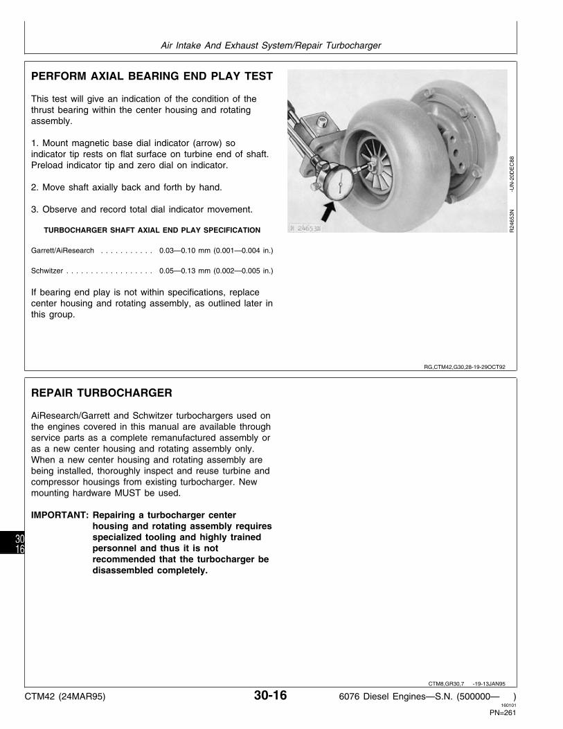
PERFORM AXIAL BEARING END PLAY TEST
This test will give an indication of the condition of thethrust bearing within the center housing and rotatingassembly.
1. Mount magnetic base dial indicator (arrow) soindicator tip rests on flat surface on turbine end of shaft.Preload indicator tip and zero dial on indicator.
2. Move shaft axially back and forth by hand.
3. Observe and record total dial indicator movement.
TURBOCHARGER SHAFT AXIAL END PLAY SPECIFICATION
Garrett/AiResearch . . . . . . . . . . . 0.03—0.10 mm (0.001—0.004 in.)
Schwitzer . . . . . . . . . . . . . . . . . . 0.05—0.13 mm (0.002—0.005 in.)
If bearing end play is not within specifications, replacecenter housing and rotating assembly, as outlined later inthis group.
R24
653N
-UN
-20D
EC
88
REPAIR TURBOCHARGER
AiResearch/Garrett and Schwitzer turbochargers used onthe engines covered in this manual are available throughservice parts as a complete remanufactured assembly oras a new center housing and rotating assembly only.When a new center housing and rotating assembly arebeing installed, thoroughly inspect and reuse turbine andcompressor housings from existing turbocharger. Newmounting hardware MUST be used.
IMPORTANT: Repairing a turbocharger centerhousing and rotating assembly requiresspecialized tooling and highly trainedpersonnel and thus it is notrecommended that the turbocharger bedisassembled completely.
RG,CTM42,G30,28-19-29OCT92
CTM8,GR30,7 -19-13JAN95
Air Intake And Exhaust System/Repair Turbocharger
CTM42 (24MAR95) 30-16 6076 Diesel Engines—S.N. (500000— )160101
PN=261
3016

DISASSEMBLE TURBOCHARGER
A—Compressor Housing C—Center Housing Assembly D—Clamp Plates E—Turbine HousingB—Clamp Plates
Cap or plug all openings (including exhaust andintake ports) and clean exterior of turbocharger with apressure spray of cleaning solvent. Dry turbochargerwith compressed air.
IMPORTANT: When cleaning turbocharger do notspray directly into compressor coveror turbine housing. Spinning rotorwith high pressure spray may causebearing damage.
Put turbocharger on a clean flat surface.
1. Scribe a location mark on the turbine housing (E),center housing (C), and compressor housing (A) toassist proper indexing of housings when turbochargeris assembled.
NOTE: Some turbochargers may not have lock plateson compressor or turbine housing cap screws.
2. If equipped, straighten ears on lock plates.
3. Remove compressor housing cap screws, lockplates (if equipped), and clamps (B).
4. Remove compressor housing. Gently tapcompressor housing with a soft hammer, if necessary,to remove. Be careful not to damage compressorhousing or compressor wheel.
5. Remove turbine housing cap screws, lock plates (ifequipped), and clamps (D).
6. Remove turbine housing. Gently tap turbinehousing with a soft hammer, if necessary, to remove.Be careful not to damage turbine housing or turbinewheel.
RG
5857
-U
N-1
3AU
G91
RG,CTM42,G30,30-19-16AUG94
Air Intake And Exhaust System/Disassemble Turbocharger
CTM42 (24MAR95) 30-17 6076 Diesel Engines—S.N. (500000— )160101
PN=262
3017

CLEAN AND INSPECT TURBINE ANDCOMPRESSOR HOUSINGS
1. Thoroughly clean compressor housing (A) and turbinehousing (C) using a commercially approved solvent only.Caustic solutions may damage housings. Dry housingswith compressed air after cleaning. After a part iscleaned, place it on a clean flat surface and inspect asoutlined below.
• Inspect turbine housing for:
—Wheel rub damage within the contour area that cannotbe polished out with 60-grit silicon carbide abrasive cloth.
—Nicks, dents or warpage that could prevent propersealing between the turbine housing and center housing.
—Corroded or stripped threaded mounting holes.
• Inspect compressor housing for:
—Wheel rub damage within the contour area that cannotA—Compressor Housingbe polished out with 80-grit silicon carbide abrasive cloth.B—Compressor ClampC—Turbine Housing
—Nicks, dents, or warpage that could prevent proper D—Turbine Clampsealing between the compressor housing and centerhousing.
—Corroded or stripped threaded mounting holes.
NOTE: Use new mounting cap screws whenturbocharger is reassembled.
2. Clean all threads in housings with a tap.
3. Replace either housing if any of the above defects arefound.
RG
5747
-U
N-0
5AU
G91
RG,CTM42,G30,31-19-15SEP94
Air Intake And Exhaust System/Clean and Inspect Turbine and Compressor Housings
CTM42 (24MAR95) 30-18 6076 Diesel Engines—S.N. (500000— )160101
PN=263
3018

REPLACE CENTER HOUSING ASSEMBLYAND ASSEMBLE TURBOCHARGER
NOTE: Center housing and rotating assembly is servicedas a complete assembly; individual internal partsare not available.
1. Carefully transfer the scribed marks from the originalcenter housing (C) to the replacement assembly, ifnecessary. Use the same procedure for the turbinehousing (E) and compressor housing (A), if they are alsobeing replaced.
2. Lay turbine housing on it’s side and install centerhousing assembly (C) into turbine housing (E). Alignscribed reference marks (scribed during disassembly) onturbine housing and center housing.
3. Apply a coat of PT569 NEVER-SEEZ Compound tocap screws. Install clamps (D), lock plates (if equipped),and cap screws. Tighten cap screws to specification.Bend lock plates up against head of cap screws.
A—Compressor HousingTURBOCHARGER CAP SCREW TORQUE SPECIFICATIONS B—Clamp Plates
C—Center Housing AssemblyD—Clamp PlatesGarrett/AiResearchE—Turbine Housing Turbine Housing-to-Center Housing . . . . . . . . . . . . 15.8—19.2 N·m
(140—170 lb-in.) Compressor Housing-to-Backplate . . . . . . . . . . . . . 15.3—18.7 N·m
(135—165 lb-in.)Schwitzer Turbine Housing-to-Center Housing . . . . . . . . . . . . . . . . 7—8 N·m
(60—70 lb-in.) Compressor Housing-to-Backplate . . . . . . . . . . . . . . . . . 7—8 N·m
(60—70 lb—in.)
4. Position compressor housing (A) onto center housingassembly (C). Align scribed reference marks (scribedduring disassembly) on compressor housing and centerhousing.
5. Apply a coat of PT569 NEVER-SEEZ Compound tocap screws. Install clamps (B), lock plates (if equipped),and cap screws. Tighten cap screws to specification.
IMPORTANT: DO NOT spin the rotor assembly withcompressed air. Damage to bearingscan occur when using compressed air.
6. After assembly, spin rotating assembly by hand tocheck for binding and wheel rub. If either conditionexists, disassemble turbocharger and determine thecause.
7. Prelube turbocharger bearings with clean engine oilbefore putting turbocharger into service.
RG
5857
-U
N-1
3AU
G91
RG,CTM42,G30,33-19-29OCT92
Air Intake And Exhaust System/Replace Center Housing Assembly and Assemble Turbocharger
CTM42 (24MAR95) 30-19 6076 Diesel Engines—S.N. (500000— )160101
PN=264
3019

PRELUBE TURBOCHARGER
IMPORTANT: DO NOT spin the rotor assembly withcompressed air. Damage to bearingscan occur when using compressed air.
Fill oil return (drain) port with clean engine oil and spinrotating assembly by hand to properly lubricate bearings.
If turbocharger is to be stored for an extended period oftime, lubricate internally and install protective covers onall openings.
RG
5858
-U
N-1
3AU
G91
INSTALL TURBOCHARGER
IMPORTANT: If turbocharger failed because offoreign material entering the air intakesystem, be sure to examine the systemand clean as required to prevent arepeat failure.
If not previously done, prime turbocharger lubricationsystem prior to mounting turbocharger on engine. Fillcenter housing with new engine oil through oil drain hole(as shown). Turn rotating assembly by hand to lubricate
6076A shown, 6076T similarbearings.
1. Apply a coat of grease to O-rings (A) and install oncompressor housing outlet (C) and coupling (B).
2. Put a new gasket on turbocharger-to-exhaust manifoldmounting surface (not shown).
RG
5859
-U
N-1
3AU
G91
RG,CTM42,G30,34-19-29OCT92
RG,CTM42,G30,35-19-29OCT92
Air Intake And Exhaust System/Install Turbocharger
CTM42 (24MAR95) 30-20 6076 Diesel Engines—S.N. (500000— )160101
PN=265
3020

NOTE: Coat coupling O-rings with liquid soap or greaseas an aid during assembly.
Install turbocharger oil drain tube on enginebefore mounting turbocharger.
Guide studs may be used to position exhaustgasket during turbocharger installation.
3. Mount turbocharger on engine, making sure coupling(E) is properly seated over compressor housing and inintake manifold.
4. Apply PT569 NEVER-SEEZ Compound to allturbocharger mounting cap screws. Install cap screwsand tighten to 24 N·m (18 lb-ft). On 6076T engines,tighten hose clamps on intake manifold and couplinghose to 9—13 N·m (12—17 lb-ft) (146—203 lb-in.).
NOTE: Remove all caps or plugs from turbochargeropenings.
A—Exhaust Elbow5. Using a new gasket, install oil drain tube (D). TightenB—Exhaust Adaptercap screws securely using JDG626 Special SocketC—Oil Inlet Line
Adapter with JDE80 and standard 9/16, 12-point, 3/8 in. D—Oil Drain Tubedrive socket. Connect oil inlet line (C) and tighten to E—Coupling26—34 N·m 19—25 lb-ft).
6. Install exhaust adapter (B) to turbine housing outletwith V-band clamp. Tighten clamp to 20 N·m (15 lb-ft).
7. Install exhaust elbow (A). Apply PT569 NEVER-SEEZCompound to mounting cap screws and tighten to 24N·m (18 lb-ft).
8. Install air intake hose and tighten hose clampssecurely.
IMPORTANT: BEFORE STARTING an engine with anew or repaired turbocharger, crank theengine over (but do not start) forseveral seconds to allow engine oil toreach turbocharger bearings. DO NOTcrank engine longer than 30 seconds ata time to avoid damage to startingmotor.
9. Start and run engine at low idle while checking oilinlet and air piping connections for leaks.
RG
5283
-U
N-2
0DE
C88
RG,CTM42,G30,39-19-24MAR95
Air Intake And Exhaust System/Install Turbocharger
CTM42 (24MAR95) 30-21 6076 Diesel Engines—S.N. (500000— )160101
PN=266
3021

REMOVE, INSPECT, AND INSTALL INTAKEMANIFOLD (6076T AND 6076H ENGINES)
IMPORTANT: All intake manifold connections at theturbocharger and engine cylinder headmust be tight to prevent loss of powerresulting from lower manifold pressure.
Intake manifold hose and cap screw connections shouldbe inspected periodically for tightness.
Whenever a tune-up has been performed on the engine,or whenever it is suspected that the horsepower outputmight be low, the intake manifold pressure (turbochargerboost should be checked. (See Group 110.)
NOTE: On 6076 HRW 33, 34, and 35 Engines, theexhaust manifold must be removed beforeremoving intake manifold.
1. On 6076T engines, loosen hose clamps (A) on lowerair intake hose.
2. On 6076H engines, remove connections fromcompressor outlet and intake manifold.
3. Disconnect aneroid line, if equipped.
4. Disconnect ether starting aid pipe from manifold, ifequipped.
5. Remove six manifold mounting cap screws and intakemanifold.
6. Inspect the intake manifold for serviceability. Replaceif it is cracked or otherwise damaged.
7. Inspect the machined mating surfaces of cylinder headand intake manifold. Clean, as required, by using ascraper and/or wire brush, and compressed air.
8. To install intake manifold, reverse removal proceduresand use new gaskets.
9. Make sure air intake hose is in good condition.Tighten hose clamps to 9—13 N·m (12—17 lb-ft)(146—203 lb-in.).
10. Tighten intake manifold attaching cap screws to 47N·m (35 lb-ft).
RG
5860
-U
N-1
3AU
G91
RG,CTM42,G30,40-19-14FEB95
Air Intake And Exhaust System/Remove, Inspect, and Install Intake Manifold
CTM42 (24MAR95) 30-22 6076 Diesel Engines—S.N. (500000— )160101
PN=267
3022

REMOVE VERTICALLY-MOUNTEDAFTERCOOLER AND INTAKE MANIFOLD(6076A ENGINES)
N CAUTION: Explosive release of fluids frompressurized cooling system can cause seriousburns. Wait until engine coolant is coolenough to touch with bare hands beforedraining. Slowly loosen radiator cap to firststop to relieve pressure.
NOTE: On some applications, aftercooler may bemounted horizontally on engine. Specificationsare the same regardless of how aftercooler ismounted.
1. Open water pump and block drain valves tocompletely drain engine coolant.
2. Thoroughly clean exterior of turbocharger (B), intakemanifold and adjacent areas to prevent entry of dirt intothe engine when parts are removed.
A—ClampsB—Turbocharger3. Remove turbocharger as described earlier in thisC—Aneroid-to-Intake Manifold Connectorgroup.D—Ether Starting Aid PipeE—Air Intake Cover Cap Screws
4. Loosen clamps (A) on inlet and outlet hoses. Removecoolant hoses from aftercooler.
5. Remove aneroid-to-intake manifold connector (C) andether starting aid pipe (D), if equipped.
6. Remove air intake cover cap screws (E).
RG
5861
-U
N-1
3AU
G91
RG,CTM42,G30,44-19-29OCT92
Air Intake And Exhaust System/Remove Vertically-Mounted Aftercooler and Intake Manifold
CTM42 (24MAR95) 30-23 6076 Diesel Engines—S.N. (500000— )160101
PN=268
3023

7. Carefully lift air intake cover (A) from intake manifold(C).
8. Remove aftercooler (B).
9. Remove and discard gaskets (D).
10. Inspect aftercooler end seal (E) and replace asneeded.
A—Air Intake CoverB—AftercoolerC—Intake ManifoldD—GasketsE—Aftercooler End Seal
RG
5862
-U
N-1
3AU
G91
11. Remove the six intake manifold-to-cylinder head capscrews (A) and remove intake manifold. Remove anddiscard all manifold gaskets.
12. Inspect and repair aftercooler. See INSPECT ANDREPAIR AFTERCOOLER (6076A ENGINES), later in thisgroup.
RG
5863
-U
N-1
3AU
G91
RG,CTM42,G30,45-19-23SEP91
RG,CTM42,G30,46-19-29OCT92
Air Intake And Exhaust System/Remove Vertically-Mounted Aftercooler and Intake Manifold
CTM42 (24MAR95) 30-24 6076 Diesel Engines—S.N. (500000— )160101
PN=269
3024

REMOVE AND DISASSEMBLEHORIZONTALLY-MOUNTED AFTERCOOLERASSEMBLY (6076A ENGINES)
NOTE: On some applications, aftercooler may bemounted vertically on engine. Specifications arethe same regardless of how aftercooler ismounted.
1. Completely drain engine coolant from aftercooler.
2. Disconnect turbocharger oil inlet (A) and return (B)lines.
3. Remove four turbocharger-to-exhaust manifold capscrews.
4. Remove coolant inlet and outlet hoses (C) fromaftercooler.
5. Remove top three intake manifold cap screws. Installguide studs at the three locations. Remove remainingcap screws.
6. Remove intake manifold and aftercooler as anassembly.
7. Remove and discard intake manifold gaskets.
8. Remove turbocharger from aftercooler cover.
RG
6486
-U
N-2
6OC
T92
RG
6487
-U
N-2
6OC
T92
9. Install JDG683 Sealing Ring Compression Tool (A)onto aftercooler coolant tubes with cross bar across slot.
10. Remove intake manifold cover (B).
11. Remove JDG683 tool.
12. Remove aftercooler core from intake manifold.
13. Inspect aftercooler end seal and replace as needed.
14. Inspect and repair aftercooler. See INSPECT ANDREPAIR AFTERCOOLER (6076A ENGINES), asdescribed earlier in this group.
RG
6488
-U
N-2
6OC
T92
RG,CTM42,G30,55-19-29OCT92
RG,CTM42,G30,59-19-29OCT92
Air Intake And Exhaust System/Remove and Disassemble Horizontally-Mounted Aftercooler Assembly
CTM42 (24MAR95) 30-25 6076 Diesel Engines—S.N. (500000— )160101
PN=270
3025

INSPECT AND REPAIR AFTERCOOLER(6076A ENGINES)
1. Inspect aftercooler for overall condition. The finsshould be reasonably straight, and cross straps shouldbe free of cracks.
2. Inspect aftercooler inlet and outlet hoses. Replaceeither hose if cracked or damaged.
3. Test the aftercooler for leaks by plugging one of thetubes (A).
4. Apply compressed air to the other tube while unit issubmerged under water. Use 140—170 kPa (1.4—1.7bar) (20—25 psi) air pressure for testing.
IMPORTANT: Coolant leakage from the aftercoolermay cause severe engine damage.
A minor leak that is accessible may be repaired.However, if the condition of the core is questionable,replace the aftercooler.
RG
5572
-U
N-0
4JU
L89
INSPECT AND REPAIR INTAKE MANIFOLDAND AIR INTAKE COVER (6076A ENGINES)
1. Inspect air intake cover (A) for cracks or damage.Replace as necessary.
2. Check intake manifold (B) for damage. Inspectmachined mounting surfaces for burrs or other defectswhich might prevent gaskets from sealing properly.Repair as required.
3. Thoroughly steam clean interior of intake manifold andcovers.
IMPORTANT: Do not use a hot tank to cleanaluminum parts as damage and severedeterioration can occur.
4. Scrape all gasket material from cylinder head andintake manifold mounting surfaces.
RG
5750
-U
N-0
5AU
G91
RG,CTM42,G30,47-19-29OCT92
RG,CTM42,G30,48-19-29OCT92
Air Intake And Exhaust System/Inspect and Repair Intake Manifold and Cover
CTM42 (24MAR95) 30-26 6076 Diesel Engines—S.N. (500000— )160101
PN=271
3026

INSTALL INTAKE MANIFOLD AND VERTICALLY-MOUNTED AFTERCOOLER (6076AENGINES)
A—Air Intake Cover C—Aftercooler E—Intake Manifold F—Gasket (2 used)B—Intake Coupling D—End Seal
6076A Engine—Two-Pass Aftercooler
Apply PT569 NEVER-SEEZ Compound to allaftercooler cover-to-intake manifold cap screws beforeassembly.
RG
5749
-U
N-0
5AU
G91
IMPORTANT: Debris left in intake manifold can causeengine damage. Make sure that theinside of manifold is clean beforeassembly.
1. Install the intake manifold on cylinder head using newgaskets.
2. Tighten the six cap screws (A) to 47 N·m (35 lb-ft).
RG
5863
-U
N-1
3AU
G91
RG,CTM42,G30,49-19-29OCT92
RG,CTM42,G30,50-19-23SEP91
Air Intake And Exhaust System/Install Intake Manifold and Vertically-Mounted Aftercooler
CTM42 (24MAR95) 30-27 6076 Diesel Engines—S.N. (500000— )160101
PN=272
3027

3. Install a new gasket (A) on top of intake manifold.
4. Install aftercooler end seal (B) on inlet and outlettubes.
5. Install aftercooler on top of intake manifold. Put a newgasket on top of aftercooler. Carefully align cap screwholes in aftercooler, intake manifold, and gaskets.
RG
5864
-U
N-1
3AU
G91
6. Install air intake cover (A) over aftercooler so inlet andoutlet tubes are protruding through hole in cover.
IMPORTANT: Improperly seated or crimped end sealcan result in loss of power andpossible engine damage. Make sureend seal is properly seated.
7. Install JDG683 Sealing Ring Compression Tool (B)onto aftercooler coolant tubes (C) with crossbar acrossslot as shown.
8. Tighten tool until air intake cover cap screw holes arealigned with holes in gaskets, aftercooler, and intakemanifold.
IMPORTANT: All intake manifold and aftercoolerconnections at the turbocharger andengine cylinder head must be tight toprevent loss of power resulting fromlower manifold pressure, and possibleengine damage.
9. Apply PT569 NEVER-SEEZ to all intakemanifold-to-aftercooler cover cap screws. Install capscrews and tighten to 34 N·m (25 lb-ft). Remove sealcompression tool.
RG
5570
-U
N-0
9JA
N90
RG,CTM42,G30,51-19-29OCT92
RG,CTM42,G30,52-19-14FEB95
Air Intake And Exhaust System/Install Intake Manifold and Vertically-Mounted Aftercooler
CTM42 (24MAR95) 30-28 6076 Diesel Engines—S.N. (500000— )160101
PN=273
3028

ASSEMBLE AND INSTALL HORIZONTALLY-MOUNTED AFTERCOOLER ASSEMBLY(6076A ENGINES)
A—Gasket (3 Used) F—Aftercooler Core K—Pipe Plug O—HoseB—Intake Manifold G—O-Ring L—End Seal P—Nipple (2 Used)C—Washer (6 Used) H—Intake Coupler M—Clamps (4 Used) Q—Cap Screw (12 Used)D—Cap Screw (6 Used) I—O-Ring N—Hose R—Washer (12 Used)E—Gasket (2 Used) J—Aftercooler Cover
IMPORTANT: Improperly seated or crimpedaftercooler end seal can result inloss of power and possible enginedamage. Make sure end seal isproperly seated.
1. Install aftercooler end seal on coolant tubes.
IMPORTANT: Debris left in intake manifold cancause engine damage. Make surethat inside of manifold is cleanbefore assembly.
2. Position aftercooler core into intake manifold usingnew gaskets.
3. Install JDG683 Sealing Ring Compression Toolonto aftercooler coolant tubes with cross bar acrossslot.
4. Tighten tool until intake manifold cover cap screwholes are aligned with holes in gaskets, aftercooler,and intake manifold. Use guide studs as needed tohold alignment.
5. Apply PT569 NEVER-SEEZ Compound to allaftercooler cover-to-intake cap screws. Tighten capscrews to 34 N·m (25 lb-ft). Remove sealcompression tool.
6. Apply multi-purpose grease to turbochargercompressor O-ring and install turbocharger ontoaftercooler cover.
RG
6489
-U
N-2
6OC
T92
RG,CTM42,G30,57-19-16AUG94
Air Intake And Exhaust System/Assemble and Install Horizontally-Mounted Aftercooler Assembly
CTM42 (24MAR95) 30-29 6076 Diesel Engines—S.N. (500000— )160101
PN=274
3029

7. Install three guide studs (A) in locations shown.
IMPORTANT: All intake manifold connections mustbe tight to prevent loss of powerresulting from lower manifold pressure,and possible engine damage.
8. Using new gaskets, install aftercooler assembly tocylinder head. Tighten cap screws to 47 N·m (35 lb-ft).
9. Connect coolant inlet and outlet hoses to aftercoolerand tighten clamps.
10. Connect turbocharger oil inlet and return lines.
RG
6490
-U
N-2
6OC
T92
RG,CTM42,G30,58-19-29OCT92
Air Intake And Exhaust System/Assemble and Install Horizontally-Mounted Aftercooler Assembly
CTM42 (24MAR95) 30-30 6076 Diesel Engines—S.N. (500000— )160101
PN=275
3030

REMOVE, INSPECT, AND INSTALLEXHAUST MANIFOLD
NOTE: On 6076 HRW 33, 34, and 35 Engines, exhaustmanifold can be removed without removing intakemanifold.
1. Remove turbocharger, air intake and manifoldassembly as described earlier in this group.
2. Remove turbocharger oil return pipe (D).
3. Remove cap screws and lift off front exhaust manifold(A) and rear exhaust manifold (B).
4. Remove and discard front-to-rear exhaust manifoldsealing ring (C).
5. Remove all residue and gasket material from gasketsurfaces.
6. Thoroughly clean passages in exhaust manifolds andexhaust elbow.
7. Inspect each exhaust manifold for cracks or damage.Inspect machined mounting surfaces for burrs or otherdefects which might prevent gaskets from sealingproperly. Replace parts as necessary. A—Front Exhaust Manifold
B—Rear Exhaust ManifoldC—Sealing Ring8. To install exhaust manifold, reverse removal procedureD—Turbocharger Oil Return Pipeand use new gaskets.
9. Coat exhaust manifold cap screws with PT569NEVER-SEEZ Compound and tighten to 47 N·m (35lb-ft) in sequence as shown.
RG
5865
-U
N-1
3AU
G91
RG
6338
-U
N-0
3AU
G92
RG,CTM42,G30,53-19-14FEB95
Air Intake And Exhaust System/Remove, Inspect, and Install Exhaust Manifold
CTM42 (24MAR95) 30-31 6076 Diesel Engines—S.N. (500000— )160101
PN=276
3031

Air Intake And Exhaust System/Remove, Inspect, and Install Exhaust Manifold
CTM42 (24MAR95) 30-32 6076 Diesel Engines—S.N. (500000— )160101
PN=277
3032

SPECIAL OR ESSENTIAL TOOLS
NOTE: Order tools according to information given in theU.S. SERVICE-GARD™ Catalog or in theEuropean Microfiche Tool Catalog (MTC).
Nozzle Thread Cleaning Brush . . . . . . . . . D17030BR
Used to clean nozzle threads in cylinder head.
RG5099 -UN-23AUG88
Flywheel Turning Tool . . . . . . . . . . . . . . . . . JDG820
Used to rotate engine to check damper radial runout andtime engine. JDE81-1 may be used also if JDG820 isnot available.
RG
7056
-U
N-1
0AU
G94
Timing Pin . . . . . . . . . . . . . . . . . . . . . . . . . JDE81-4
Lock engine at TDC when timing valve train, adjustingvalve clearance, and installing fuel injection pump. Usewith JDG820 and JDE81-1 Flywheel Turning Tools.
RG5068 -UN-23AUG88
Serrated Wrench . . . . . . . . . . . . . . . . . . . . . JDE90
Use to hold injection pump fuel outlet fittings on Bosch“P” pump from turning when loosening and tighteningfuel pipe connections.
RG5290 -UN-15OCT92
Nozzle Socket . . . . . . . . . . . . . . . . . . . . . . . JDE92
Used to remove and install 21 mm injection nozzles.
R28
362N
-UN
-20D
EC
88
DX,TOOLS -19-05JUN91
S53,D17030,BR -19-16FEB87
RG,JDG820 -19-14FEB95
RG,JDE814,86 -19-14FEB95
S54,JDE90 -19-29OCT92
S11,3010,OU -19-16AUG94
Group 35Fuel System
CTM42 (24MAR95) 35-1 6076 Diesel Engines—S.N. (500000— )160101
PN=278
351

Tap . . . . . . . . . . . . . . . . . . . . . . . . . . . . . . . JDF5
Used to restore nozzle threads in cylinder head.
RG5100 -UN-23AUG88
Nozzle Cleaning Kit . . . . . . . . . . . . . JDF13 (JDE105)
Used to clean injection nozzles.
RG
4953
-U
N-1
4DE
C88
Driver . . . . . . . . . . . . . . . . . . . . . . . . . . . . . JDF15
Used to install spindle seals in fuel supply pumps.
RG
2017
-U
N-3
0NO
V88
Crowsfoot Wrench . . . . . . . . . . . . . . . . . . . . JDF22
Use to loosen and tighten fuel pipes at injection nozzlesand at injection pump.
RG5288 -UN-23AUG88
Special Socket . . . . . . . . . . . . . . . . . . . . . . . JDF33
Used to loosen and tighten fast idle stop screw onNippondenso injection pumps when adjusting enginespeeds.
RG5287 -UN-23AUG88
Nozzle Seat Reamer . . . . . . . . . . . . . . . . . . JDG609
Used to clean carbon from nozzle seats in cylinder head.
RG5289 -UN-23AUG88
S53,JDF5 -19-08MAR94
S11,3010,OW -19-09SEP91
S55,3010,BA -19-25JUL91
S53,JDF22,1 -19-02DEC87
S53,JDF33 -19-02DEC87
S53,JDG609 -19-02DEC87
Fuel System/Special or Essential Tools
CTM42 (24MAR95) 35-2 6076 Diesel Engines—S.N. (500000— )160101
PN=279
352

Injection Pump Timing Pin . . . . . . . . . . . . . . JDG886
Used to set in-line fuel injection pump timing prior toremoval of pump.
RG7212 -UN-23JUL94
Injection Pump Drive Gear Puller . . . . . . . . . JDG670A
Remove drive gear from tapered shaft on StanadyneDB4 fuel injection pumps.
RG
6032
-U
N-1
3JA
N92
A—Fuel Injection Nozzle Tester . . . D01109AA (Y900)
B—Fuel Line Assembly . . . . . . . . . . . . . . . Y900-2A*
C—Adapter Nut . . . . . . . . . . . . . . . . . . . . Y900-21**
D—Straight Adapters . . . . . . . . Y900-7* and Y900-15*
Used to test operational performance and openingpressure of nozzles.
*Included in D01110AA (Y910A) Adapter Set.
**May be used instead of Y900-7 and Y900-15.
RG
4954
-U
N-1
4DE
C88
RG,JDG886 -19-10AUG94
RG,JDG670A,400 -19-02OCT92
S11,3010,OX -19-09SEP91
Fuel System/Special or Essential Tools
CTM42 (24MAR95) 35-3 6076 Diesel Engines—S.N. (500000— )160101
PN=280
353

OTHER MATERIAL
Name Use
AR54749 Soap Lubricant Injection pump mounting flange O-ring.
PT569 NEVER-SEEZ Compound Gland nut threads and fuel injection nozzle barrel.
LOCTITE 242 (TY9370/T43512) Thread Lock Injection pump timing hole plug.and Sealer
LOCTITE 592 (TY9374/TY9375) Pipe Sealant Fuel filter drain plug and bleed plug.with TEFLON
DIESEL FUEL SYSTEM SPECIFICATIONS
ITEM SPECIFICATION
Engine Operating Speeds . . . . . . . . . . . . . . . . . . . . . . . . . . . . . . . . . . . . . . . . See Applicable Machine TM
Injection Pump Timing to Engine . . . . . . . . . . . . . . . . . . . . . . . . . . . . . . . . . . . . . . . . . . . . . . . . . . TDC
Hydraulic Aneroid Activator Operating Pressure (If Equipped) . . . . . . . . . . . . . . . . 100 kPa (1.0 bar) (14.5 psi)
Overflow Valve Opening Pressure . . . . . . . . . . . . . . . . . . . . . . . . 130—180 kPa (1.3—1.8 bar) (19—26 psi)
Fuel Injection Nozzles . . . . . . . . . . . . . . . . . . . . . . . . . . . . . . . . . . . . . . . . . . . . . . . . . . . . . . . . 21 mm
New Nozzle Opening Pressure (for tip sizes) 7 x 0.22 mm, 7 x 0.23 mm, 7 x 0.255 mm . . . . . . . . . 29 000—30 200 kPa (290—302 bar) (4200—4370 psi)
Used Nozzle Minimum Opening Pressure (for tip sizes) 7 x 0.22 mm, 7 x 0.23 mm, 7 x 0.255 mm . . . . . . . . . . . . . . . . . . . . . . . . 26 200 kPa (262 bar) (3800 psi)
Injection Pump Static Timing: In-Line Pumps (Robert Bosch/Nippondenso) . . . . . . . . . . . . Lock No. 1 cylinder at TDC compression stroke.
Align mark on injection pump drive hub with pointer mark.Install pump, recheck alignment of marks.
Rotary Pumps (Stanadyne) . . . . . . . . . . . . . . . . . . . . . . . Lock No. 1 cylinder at TDC compression stroke.Align marks on injection pump mounting flange
with factory (dynamic) timing mark on cylinder block.
RG,CTM42,G35,76-19-15SEP94
RG,CTM42,G35,1 -19-16AUG94
Fuel System/Diesel Fuel System Specifications
CTM42 (24MAR95) 35-4 6076 Diesel Engines—S.N. (500000— )160101
PN=281
354

DIESEL FUEL SYSTEMSPECIFICATIONS—CONTINUED
TORQUES
Injection Pump-to-Cylinder Block Stud Nuts . . . . . . . . . . . . . . . . . . . . . . . . . . . . . . . . . . . 47 N·m (35 lb-ft)
Injection Pump Drive Gear-to-Pump Hub Cap Screws: A-Series Injection Pumps* . . . . . . . . . . . . . . . . . . . . . . . . . . . . . . . . . . . . . . . . . . . . . . 47 N·m (35 lb-ft) P-Series Injection Pumps* . . . . . . . . . . . . . . . . . . . . . . . . . . . . . . . . . . . . . . . . . . . . . . 61 N·m (45 lb-ft)
Injection Pump Drive Gear-to-Tapered Shaft Hex Nut: Stanadyne DB4 Injection Pumps . . . . . . . . . . . . . . . . . . . . . . . . . . . . . . . . . . . . . . . . 142 N·m (105 lb-ft)
Injection Line Connectors . . . . . . . . . . . . . . . . . . . . . . . . . . . . . . . . . . . . . . . . . . . . . . . 27 N·m (20 lb-ft)
Nozzle Gland Nut-to-Cylinder Head . . . . . . . . . . . . . . . . . . . . . . . . . . . . . . . . . . . . . . . . 88 N·m (65 lb-ft)
Nozzle Retaining Nut . . . . . . . . . . . . . . . . . . . . . . . . . . . . . . . . . . . . . . . . . . . . 60—79 N·m (44—68 lb-ft)
Supply Pump Mounting Stud Nuts . . . . . . . . . . . . . . . . . . . . . . . . . . . . . 5—7 N·m (4—5 lb-ft)(45—60 lb-in.)
Leak-off Connectors . . . . . . . . . . . . . . . . . . . . . . . . . . . . . . . . . . . . . . . 17 N·m (13 lb-ft)(150 lb-in.) Max.
Fuel Filter Base-to-Cylinder Block . . . . . . . . . . . . . . . . . . . . . . . . . . . . . . . . . . . 34—54 N·m (25—40 lb-ft)
Fuel Pipe Connections at Filter Base . . . . . . . . . . . . . . . . . . . . . . . . . . . . 17 N·m (13 lb-ft)(150 lb-in.) Max.
Injection Pump Drive Gear Cover Cap Screws . . . . . . . . . . . . . . . . . . . . . . . . . . . . . . . . . 27 N·m (20 lb-ft)
Fuel Shutoff Solenoid Bracket-to-Oil Filter Housing Cap Screws . . . . . . . . . . . . . . . . . . . . . 23 N·m (17 lb-ft)
Fuel Shutoff Solenoid-to-Bracket Hex Nuts . . . . . . . . . . . . . . . . . . . . . . . . . . . . . . . 7 N·m (5 lb-ft)(60 lb-in.)
*Refer to IDENTIFICATION OF IN-LINE INJECTION PUMPS later inthis group. RG,CTM42,G35,98-19-17MAR95
Fuel System/Diesel Fuel System Specifications
CTM42 (24MAR95) 35-5 6076 Diesel Engines—S.N. (500000— )160101
PN=282
355
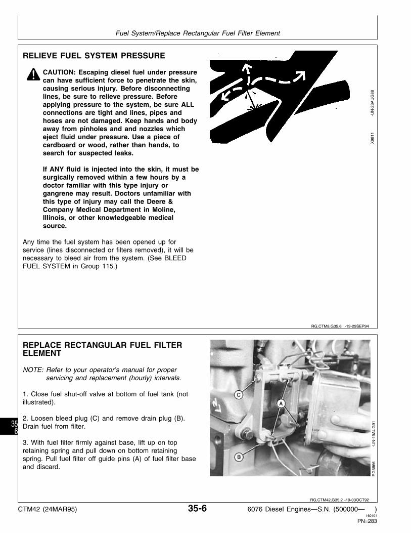
RELIEVE FUEL SYSTEM PRESSURE
N CAUTION: Escaping diesel fuel under pressurecan have sufficient force to penetrate the skin,causing serious injury. Before disconnectinglines, be sure to relieve pressure. Beforeapplying pressure to the system, be sure ALLconnections are tight and lines, pipes andhoses are not damaged. Keep hands and bodyaway from pinholes and and nozzles whicheject fluid under pressure. Use a piece ofcardboard or wood, rather than hands, tosearch for suspected leaks.
If ANY fluid is injected into the skin, it must besurgically removed within a few hours by adoctor familiar with this type injury organgrene may result. Doctors unfamiliar withthis type of injury may call the Deere &Company Medical Department in Moline,Illinois, or other knowledgeable medicalsource.
Any time the fuel system has been opened up forservice (lines disconnected or filters removed), it will benecessary to bleed air from the system. (See BLEEDFUEL SYSTEM in Group 115.)
X98
11
-UN
-23A
UG
88
REPLACE RECTANGULAR FUEL FILTERELEMENT
NOTE: Refer to your operator’s manual for properservicing and replacement (hourly) intervals.
1. Close fuel shut-off valve at bottom of fuel tank (notillustrated).
2. Loosen bleed plug (C) and remove drain plug (B).Drain fuel from filter.
3. With fuel filter firmly against base, lift up on topretaining spring and pull down on bottom retainingspring. Pull fuel filter off guide pins (A) of fuel filter baseand discard.
RG
5866
-U
N-1
9AU
G91
RG,CTM8,G35,6 -19-29SEP94
RG,CTM42,G35,2 -19-03OCT92
Fuel System/Replace Rectangular Fuel Filter Element
CTM42 (24MAR95) 35-6 6076 Diesel Engines—S.N. (500000— )160101
PN=283
356

4. Install fuel filter onto guide pins on fuel filter base.Hold filter firmly against base.
5. Secure bottom retaining spring first, then secure topretaining spring.
6. Install drain plug, shown installed. Tighten bleed plugand drain plug securely. Do not overtighten.
7. Open fuel shut-off valve and bleed fuel system. (SeeBLEED THE FUEL SYSTEM, in Group 115.)
RG
5867
-U
N-1
9AU
G91
REPLACE FUEL CHECK VALVE
IMPORTANT: Remove fuel check valve only forreplacement purposes, since O-ringseals tightly in bore, removal usuallydamages check valve assembly.
1. Drain and remove fuel filter (A) as described earlier inthis group.
2. Remove fuel filter inlet line (B), (shown removed).
3. Inspect and clean fuel filter base as described later inthis group.
4. Remove check valve adapter housing (C) from fuelfilter base, and discard.
5. Install new check valve assembly and tightensecurely.
6. Install fuel inlet line and tighten connection 17 N·m(13 lb-ft)(150 in-lb) maximum. DO NOT overtighten.
7. Install fuel filter and bleed fuel system. (See BLEEDTHE FUEL SYSTEM, in Group 115.)
RG
5868
-U
N-1
9AU
G91
RG,CTM42,G35,3 -19-03OCT92
RG,CTM42,G35,4 -19-17MAR95
Fuel System/Replace Fuel Check Valve
CTM42 (24MAR95) 35-7 6076 Diesel Engines—S.N. (500000— )160101
PN=284
357

REPLACE ROUND FUEL FILTER ELEMENT
1. Thoroughly clean exterior of filter element (C) andbase (A). Also clean around filter mounting area onblock.
2. Rotate retaining ring (D) counterclockwise (left) 1/4turn. Lifting ring as it is rotated helps to get it pastretaining detent. Ring should now drop down and releasefilter from base.
NOTE: Notice indexing keys (F) on filter element. Thesekeys insure proper alignment of filter element tofilter base.
3. Index filter element until longer, vertical keys areoriented away from engine. Insert filter element into basesecurely. It may be necessary to rotate filter slightly toleft or right for correct alignment.
4. Install retaining ring to filter base, making certain dustseal (B) is in place on filter base. Tighten retaining ringuntil it locks into detent position. A—Filter Element Base
B—Dust SealC—Filter Element5. Loosen bleed screw (E) and bleed fuel system. (SeeD—Retaining RingBLEED THE FUEL SYSTEM, in Group 115.)E—Bleed ScrewF—Indexing Keys
RG
6445
-U
N-1
5OC
T92
RG,CTM42,G35,91-19-28OCT92
Fuel System/Remove Round Fuel Filter Element
CTM42 (24MAR95) 35-8 6076 Diesel Engines—S.N. (500000— )160101
PN=285
358

IDENTIFICATION OF MECHANICAL FUELSUPPLY PUMPS
NOTE: 6076TRW31 engines are epuipped withStanadyne DB4 rotary-style injection pump whichuses an electric fuel supply pump, all other 6076engines are equipped with an in-line injectionpump (Bosch or Nippondenso) and mechanicalsupply pump.
Mechanical fuel supply pumps mount onto the side ofthe in-line injection pump. A tappet on the supply pumpis activated by the injection pump rotating cam duringengine revolution. The tappet on the supply pump maybe either a roller-type tappet (Nippondenso) or a flatplunger-type tappet (Bosch). The type of tappet can bedetermined visually, when the fuel supply pump isremoved, or by the “size of injection pump” indicator inthe pump model number.
FUEL SUPPLY PUMP IDENTIFICATION NUMBER
FP/KE22AD290FP . . . . . . . . . . . . . . . . . . . . . . . . . . . . . . . . . Fuel Supply Pump /K . . . . . . . . . . . . . . . . . . . . . . . . . Single-Acting Plunger Pump E . . . . . . . . . . . . . . . . . . . . . . Pump Driven by Eccentric Cam 22 . . . . . . . . . . . . . . . . . . . . . . . . Diameter of Plunger in mm A . . . . . . . . . . . . . . . . . . . . . . Size of Injection Pump Used D . . . . . . . . . . . . . . . . . . . . . . . . . . . . . . . Pump Version 290 . . . . . . . . . . . . . . . . Manufacturer’s Design Number
RG
2170
-U
N-2
3AP
R94
RG,CTM42,G35,92-19-17MAR95
Fuel System/Identification of fuel supply and fuel injection pumps
CTM42 (24MAR95) 35-9 6076 Diesel Engines—S.N. (500000— )160101
PN=286
359

REMOVE MECHANICAL FUEL SUPPLYPUMP
NOTE: To diagnose mechanical fuel supply pumpmalfunctions or test for leaks, refer to Group 115.
Thoroughly clean exterior of supply pump. Also cleanaround supply pump mounting area on injection pumphousing.
1. Disconnect fuel inlet line (A), shown disconnected,and outlet line (B). Cap all line openings socontaminants do not enter fuel system.
2. Remove three mounting nuts (C).
3. Pull fuel supply pump straight out from injection pumphousing. Cover supply pump mounting bore so debriscannot enter injection pump.
RG
5893
-U
N-1
9AU
G91
RG,CTM42,G35,8 -19-03OCT92
Fuel System/Remove Mechanical Fuel Supply Pump
CTM42 (24MAR95) 35-10 6076 Diesel Engines—S.N. (500000— )160101
PN=287
3510

TEST MECHANICAL FUEL SUPPLY PUMPFOR LEAKS
Fuel delivery pressure should be checked beforeremoving supply pump from injection pump. (SeeCHECK MECHANICAL FUEL SUPPLY PUMPOPERATION, in Group 115.)
1. Connect compressed air line (A) to a pressure gauge(B) and to supply pump inlet fitting. Air line should havea regulating valve to control pressure.
2. Cap or plug supply pump outlet fitting (C).
3. Submerge supply pump in a container of clean dieselfuel. Regulate air pressure to 200 kPa (2.0 bar) (29 psi).
4. Move roller tappet (Nippondenso pumps) or spindle(Bosch pumps) in and out by hand. No air bubblesshould appear around roller tappet or spindle bore.
NOTE: If bubbles appear, it is an indication that eitherthe O-ring seal is defective or spindle or tappet isworn (or possibly both).
IMPORTANT: Serious injection pump or enginedamage could occur, if enough dieselfuel leaks past spindle and seal. Fuelleakage past spindle dilutes engine oil.
RG
5894
-U
N-1
9AU
G91
RG,CTM42,G35,9 -19-28OCT92
Fuel System/Test Mechanical Fuel Supply Pump for Leaks
CTM42 (24MAR95) 35-11 6076 Diesel Engines—S.N. (500000— )160101
PN=288
3511

DISASSEMBLE MECHANICAL (ROLLER TAPPET) FUEL SUPPLY PUMP—NIPPONDENSO
1—Hand Primer 6—Elbow Fitting (2 used) 10—O-Ring/Spindle Seal 14—Pump Housing2—Washer (4 used) 7—Plug 11—Roller Tappet Assembly 15—Pressure Spindle3—Spring (2 used) 8—Washer 12—Snap Ring 16—Plunger4—Valve 9—Spring 13—Plug 17—Banjo fitting5—O-Ring (2 used)
1. Remove elbow fitting (6) by loosening locknut andunscrewing elbow fitting from pump housing. Removeand discard O-ring (5).
RG
5901
-U
N-1
9AU
G91
2. Remove hand primer (A), banjo fitting (B), and plug(C) from housing. Discard copper washer.
3. Remove plug (D) from housing. Discard copperwashers.
A—Hand PrimerB—Banjo FittingC—PlugD—Plug
RG
5945
-U
N-2
8AU
G91
RG,CTM42,G35,10-19-14FEB95
RG,CTM42,G35,61-19-02NOV92
Fuel System/Disassemble Mechanical Fuel Supply Pump (Nippondenso)
CTM42 (24MAR95) 35-12 6076 Diesel Engines—S.N. (500000— )160101
PN=289
3512

4. Remove valves (A) and springs (B).
RG
2323
-U
N-3
0NO
V88
5. Remove plug (A), spring (B) and plunger (C) frompump housing. Discard copper washer.
6. Remove snap ring (D) from outer circumference ofpump housing neck.
NOTE: Snap ring has a tang on one end which extendsvertically down through a hole in pump housingto retain roller tappet assembly.
A—PlugB—SpringC—PlungerD—Snap Ring
RG
2318
-U
N-2
0DE
C88
7. Remove roller tappet (A) and spindle (B) from pumphousing. Remove and discard O-ring on spindle.
RG
4028
-U
N-3
0NO
V88
RG,CTM42,G35,62-19-10SEP91
S55,3010,Y -19-03OCT92
S55,3010,Z -19-03OCT92
Fuel System/Disassemble Mechanical Fuel Supply Pump (Nippondenso)
CTM42 (24MAR95) 35-13 6076 Diesel Engines—S.N. (500000— )160101
PN=290
3513

NOTE: Spindle/seal O-ring (B) is pressed into pumphousing. This seal keeps diesel fuel from leakingpast spindle (A) and entering injection pumpcrankcase.
8. Remove spindle seal from housing using needle nosepliers. Discard seal.
RG
4029
-U
N-3
0NO
V88
INSPECT AND REPAIR MECHANICAL(ROLLER TAPPET) FUEL SUPPLY PUMPCOMPONENTS—NIPPONDENSO
1. Inspect supply pump housing for cracks and wear. Besure valve seating areas are not pitted. Replace housingas necessary.
2. Check roller tappet and plunger bore for wear andscoring. Remove any deposits in housing with a suitablesolvent. Rinse housing in clean diesel fuel.
3. Check condition of threads for inlet and outlet fittings.Pump elbow fittings have 1/2-20 threads.
RG
5902
-U
N-1
9AU
G91
4. Inspect roller (A) OD for excessive wear. Be sureroller turns freely on pin (B) and in tappet (C).
5. Inspect sliding blocks (D). Edges should be squareand unpitted. Blocks should slide in and out of tappeteasily.
6. Inspect tappet for wear and scoring. Remove anydeposits with a suitable solvent.
Be sure land on tappet that contacts pressure spindle isflat and undamaged. A—Roller
B—PinC—TappetD—Sliding Block (2 used)
RG
2321
-U
N-3
0NO
V88
S55,3010,AA -19-03OCT92
RG,CTM42,G35,11-19-14FEB95
S11,3010,QN -19-24NOV86
Fuel System/Inspect and Repair Mechanical Fuel Supply Pump (Nippondenso)
CTM42 (24MAR95) 35-14 6076 Diesel Engines—S.N. (500000— )160101
PN=291
3514

7. Inspect pressure spindle (A) and plunger (B) for pitsand burrs. Replace parts as necessary.
8. Inspect spring (C) for cracks and distortion. Replaceparts as necessary.
RG
2322
-U
N-3
0NO
V88
9. Inspect valves (A), especially valve face, for cracks,pits and wear. Replace as necessary.
10. Spring (B) should not be bent or broken.
RG
2323
-U
N-3
0NO
V88
ASSEMBLE MECHANICAL (ROLLERTAPPET) FUEL SUPPLYPUMP—NIPPONDENSO
IMPORTANT: Always use new copper gaskets. Dipparts in clean diesel fuel beforeassembly. Hands should be wet withdiesel fuel when assembling internalcomponents of fuel supply pump.
1. Install new spindle seal (C) into pump housing (B)using JDF15 Driver (A). Be sure seal is started straightin housing bore and drive until driver contacts housing.
2. To assemble supply pump, reverse disassemblyprocedure using new O-rings.
Perform leak test described in Group 115.
RG
2013
-U
N-3
0NO
V88
S11,32010,QO -19-24NOV86
S11,3010,QP -19-24NOV86
RG,CTM42,G35,12-19-14FEB95
Fuel System/Assemble Mechanical Fuel Supply Pump (Nippondenso)
CTM42 (24MAR95) 35-15 6076 Diesel Engines—S.N. (500000— )160101
PN=292
3515

DISASSEMBLE MECHANICAL (FLATPLUNGER) FUEL SUPPLY PUMP—ROBERTBOSCH
1. Remove inlet elbow fitting (A) and outlet elbow fitting(B) by loosening locknut and unscrewing fittings frompump housing. Remove and discard O-rings.
2. Remove hand primer (C) from housing. Remove anddiscard copper washer (D).
A—Inlet Elbow FittingB—Outlet Elbow FittingC—Hand Primer PumpD—Copper Washer
RG
5909
-U
N-1
9AU
G91
3. Remove fuel pump outlet valve fitting (A) from pumphousing (C). Remove and discard O-ring (B).
4. Remove spindle (I) and spindle guide plug (H) byunscrewing guide plug from pump housing. Remove anddiscard O-rings (J and G).
5. Remove plunger (F), spring wear plates (D), andspring (E).
A—Outlet Valve FittingB—O-RingC—Supply Pump HousingD—Spring Wear PlatesE—SpringF—Plunger AssemblyG—O-RingH—Spindle Guide PlugI—SpindleJ—O-Ring
RG
5912
-U
N-2
8AU
G91
RG,CTM42,G35,63-19-14FEB95
RG,CTM42,G35,64-19-28OCT92
Fuel System/Disassemble Mechanical Fuel Supply Pump (Robert Bosch)
CTM42 (24MAR95) 35-16 6076 Diesel Engines—S.N. (500000— )160101
PN=293
3516

6. Push inlet valve (B) and seal (C) out of plunger (A) bypoking rounded end of a small pin through closed end ofplunger.
NOTE: The outlet valve is located in outlet valve fitting(D) and is not removable from fitting.
A—PlungerB—Inlet Valve SealC—Inlet ValveD—Outlet Valve and Fitting
RG
5913
-U
N-2
8AU
G91
INSPECT AND REPAIR MECHANICAL (FLATPLUNGER) FUEL SUPPLY PUMP—ROBERTBOSCH
1. Inspect supply pump housing (C) for cracks and wear.Be sure plunger bore is not worn or scored. Checkcondition of threads for inlet and outlet fittings, handprimer pump, and spindle guide plug (H).
2. Inspect spindle (I) for wear, scoring on OD, and burrs.Check lands that contact plunger and fuel pump camlobe to be sure they are flat and undamaged. Removeany deposits with a suitable solvent.
3. Inspect plunger (F) for burrs and pits. Remove any A—Outlet Valve FittingB—O-Ringdeposits with a suitable solvent.C—Supply Pump HousingD—Spring Wear Plates
4. Inspect spring (E) and wear plates (D) for cracks, E—Springdistortion, and wear. F—Plunger Assembly
G—O-RingH—Spindle Guide Plug5. Inspect inlet valve and seal (not shown) for wear,I—Spindlecracks, and broken or missing spring.J—O-Ring
6. Inspect outlet valve and fitting (A) for wear, cracks,broken or missing spring, or damaged threads.
If any of the above parts are damaged, worn, ordefective, replace as necessary.
RG
5912
-U
N-2
8AU
G91
RG,CTM42,G35,65-19-03OCT92
RG,CTM42,G35,66-19-14FEB95
Fuel System/Inspect and Repair Mechanical Fuel Supply Pump (Robert Bosch)
CTM42 (24MAR95) 35-17 6076 Diesel Engines—S.N. (500000— )160101
PN=294
3517

ASSEMBLE MECHANICAL (FLAT PLUNGER)FUEL SUPPLY PUMP—ROBERT BOSCH
IMPORTANT: Always use new copper gaskets andO-rings. Dip parts in clean diesel fuelbefore assembly. Hands should be wetwith diesel fuel when assemblinginternal components of fuel supplypump.
1. Assemble seal (B) into plunger (C) so flat side of sealis against closed end of plunger. Install inlet valve (A)into plunger so spring side of valve protrudes throughcenter of seal and faces toward closed end of plunger.
2. To assemble supply pump, reverse disassemblyprocedure using new O-rings and copper washer.
Perform leak test described in Group 115.
RG
5946
-U
N-2
8AU
G91
INSTALL MECHANICAL FUEL SUPPLYPUMP
IMPORTANT: Before installing supply pump, testpump to make sure fuel will not leakaround spindle and spindle seal. (SeeTEST MECHANICAL FUEL SUPPLYPUMP FOR LEAKS, in Group 115.)
1. On Nippondenso (roller tappet) pumps, put a newO-ring in counterbore of injection pump housing next tofuel supply pump mounting face.
On Robert Bosch pumps, install a new gasket on supplypump mounting face (A).
Bosch pump shown
2. Position pump over mounting studs. Tighten mountingstud nuts 5—7 N·m (4—5 lb-ft) (45—60 lb-in.).
3. Install fuel inlet and outlet lines when engine isinstalled in vehicle. Tighten all connections securely.
4. Bleed fuel system. (See BLEED THE FUEL SYSTEM,in Group 115.)
RG
5906
-U
N-1
9AU
G91
RG,CTM42,G35,67-19-14FEB95
RG,CTM42,G35,14-19-14FEB95
Fuel System/Install Mechanical Fuel Supply Pump
CTM42 (24MAR95) 35-18 6076 Diesel Engines—S.N. (500000— )160101
PN=295
3518

REMOVE AND INSTALL ELECTRIC FUELSUPPLY PUMP—6076TRW31 ENGINES
NOTE: Refer to Group 115 for operation and test ofelectric fuel supply pump.
1. Thoroughly clean exterior of supply pump andmounting area on block.
2. Disconnect fuel inlet line (A) and outlet line (B). Capall line openings.
3. Disconnect wiring harness (C) at connector.
4. Remove mounting bracket (D).
5. Remove pump from mounting bracket.
6. To install pump, reverse disassembly procedure.Tighten mounting bracket cap screws to 8.5 N·m (6 lb-ft)(75 lb-in.).
A—Fuel Inlet LineB—Fuel Outlet Line
7. Check for leaks during engine operation. C—Wiring HarnessD—Mounting Bracket
RG
6460
-U
N-2
6OC
T92
RG,CTM42,G35,81-19-17MAR95
Fuel System/Remove and Install Electric Fuel Supply Pump
CTM42 (24MAR95) 35-19 6076 Diesel Engines—S.N. (500000— )160101
PN=296
3519

CLEAN OR REPLACE ELECTRIC FUELSUPPLY PUMP FILTERSCREEN—6076TRW31 ENGINES
Electric supply pump filter screen element (B) should becleaned frequently under normal engine operatingconditions. If output flow or pressure is belowspecifications, it may be result of a partially obstructedfilter screen. Refer to operator’s manual forrecommended hourly maintenance interval.
1. Remove cap screws from cover plate (D). Removecover and gasket (C) from pump (A).
2. With clean hands, remove filter screen from pump.
IMPORTANT: Do not clean or touch screen or insideof pump with cotton cloth. The smallestpiece of lint may cause fuel systemcontamination.
3. Using compressed air, clean by blowing air throughfilter from inside to outside. If screen is damaged, eitherby holes or sealing surfaces, it must be replaced.
4. Install screen with flange end of screen against filterplate gasket.
5. Install cover plate.A—Electric Fuel Supply PumpB—Filter Screen ElementC—GasketD—Cover Plate
RG
6452
-U
N-1
3OC
T92
RG,CTM42,G35,82-19-17MAR95
Fuel System/Clean or Replace Electric Fuel Supply Pump Filter Screen
CTM42 (24MAR95) 35-20 6076 Diesel Engines—S.N. (500000— )160101
PN=297
3520

REPAIR ANEROID—IF EQUIPPED
For aneroid repair and adjustment, have an authorizeddiesel repair station perform the work.
The aneroid controls fuel delivery when intake manifoldpressure is about 100 kPa (1.00 bar) (15 psi) or less.Therefore, all final adjustments are to be made on thetest stand with aneroid mounted on injection pump.
IMPORTANT: Correct aneroid adjustments areessential for satisfactory engineperformance. Whenever aneroid hasbeen disassembled or adjustmentshave been altered, injection pump(including aneroid) must be calibratedon test stand before releasing pump forservice.
REMOVE HYDRAULIC ANEROIDACTIVATOR—IF EQUIPPED
NOTE: The hydraulic aneroid activator is located on backside of governor housing next to cylinder block.
1. Remove injection pump as described later in thisgroup.
2. Remove special screw (A), copper washers (B) andbanjo connector (C). Discard copper washers.
3. Remove spring (D), restricter wire (E) and capillaryvalve (F) from activator housing (G). Remove activator
A—Special Screwhousing.B—Copper Washer (2 used)C—Banjo Connector
NOTE: Do not bend restricter wire or other activator D—Springparts. E—Restricter Wire
F—Capillary ValveG—Activator Housing
RG
3546
-U
N-2
0DE
C88
S11,3010,PG -19-14FEB95
RG,CTM42,G35,70-19-14FEB95
Fuel System/Remove Hydraulic Aneroid Activator
CTM42 (24MAR95) 35-21 6076 Diesel Engines—S.N. (500000— )160101
PN=298
3521
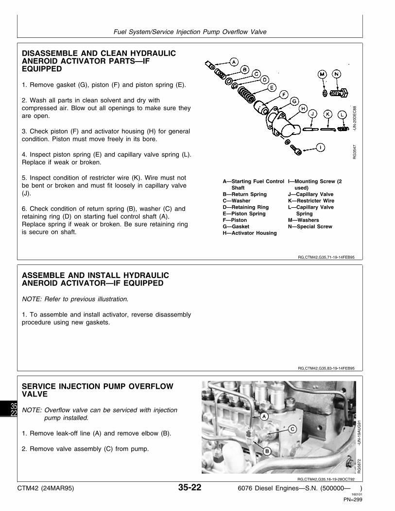
DISASSEMBLE AND CLEAN HYDRAULICANEROID ACTIVATOR PARTS—IFEQUIPPED
1. Remove gasket (G), piston (F) and piston spring (E).
2. Wash all parts in clean solvent and dry withcompressed air. Blow out all openings to make sure theyare open.
3. Check piston (F) and activator housing (H) for generalcondition. Piston must move freely in its bore.
4. Inspect piston spring (E) and capillary valve spring (L).Replace if weak or broken.
5. Inspect condition of restricter wire (K). Wire must notA—Starting Fuel Control I—Mounting Screw (2
be bent or broken and must fit loosely in capillary valve Shaft used)(J). B—Return Spring J—Capillary Valve
C—Washer K—Restricter WireD—Retaining Ring L—Capillary Valve6. Check condition of return spring (B), washer (C) andE—Piston Spring Springretaining ring (D) on starting fuel control shaft (A).F—Piston M—Washers
Replace spring if weak or broken. Be sure retaining ring G—Gasket N—Special Screwis secure on shaft. H—Activator Housing
RG
3547
-U
N-2
0DE
C88
ASSEMBLE AND INSTALL HYDRAULICANEROID ACTIVATOR—IF EQUIPPED
NOTE: Refer to previous illustration.
1. To assemble and install activator, reverse disassemblyprocedure using new gaskets.
SERVICE INJECTION PUMP OVERFLOWVALVE
NOTE: Overflow valve can be serviced with injectionpump installed.
1. Remove leak-off line (A) and remove elbow (B).
2. Remove valve assembly (C) from pump.
RG
5872
-U
N-1
9AU
G91
RG,CTM42,G35,71-19-14FEB95
RG,CTM42,G35,83-19-14FEB95
RG,CTM42,G35,16-19-28OCT92
Fuel System/Service Injection Pump Overflow Valve
CTM42 (24MAR95) 35-22 6076 Diesel Engines—S.N. (500000— )160101
PN=299
3522

3. Remove reducer (A) and copper washer (B) fromvalve body (C). Discard copper washer.
4. Unscrew spring seat (D); then remove spring (E) andvalve (F).
5. Inspect for foreign material imbedded in seat of nylonvalve.
6. Check spring to see that it is not weak or broken.
7. Wash all parts in solvent and air dry.
NOTE: There is no adjustment on valve to regulateA—Reducerhousing pressure. If suspected that valve isB—Washermalfunctioning replace valve to restore properC—Valve Body
operation. D—Spring SeatE—Spring
8. Reverse order of removal for reassembly of overflow F—ValveG—Washervalve. Install new copper washers.
RG
3549
-U
N-2
0DE
C88
RG,CTM42,G35,72-19-03OCT92
Fuel System/Service Injection Pump Overflow Valve
CTM42 (24MAR95) 35-23 6076 Diesel Engines—S.N. (500000— )160101
PN=300
3523

REMOVE AND INSTALL FUEL SHUTOFF SOLENOID
A—Wiring Connector D—Cotter Pin G—Lock Washer and Screws J—Solenoid MountingB—Fuel Shutoff Solenoid E—Washer H—Hex Nuts BracketC—Solenoid Shaft F—Fuel Shutoff Lever I—Cap Screws
1. Disconnect electrical wiring connector (A) insolenoid lead.
2. Remove cotter pin (D), washer (E), and pullsolenoid shaft (C) out of fuel shutoff lever (F).
3. Remove fuel shutoff solenoid (B) from solenoidmounting bracket (J) by removing hex nuts (H), lockwashers, and machine screws (G).
4. If solenoid mounting bracket is to be removed,remove cap screws (I) and lock washers that fastenthe bracket to oil filter housing.
IMPORTANT: Fuel shutoff solenoid linkage shouldmove freely back and forth. On “A”pumps if linkage is binding, checkpump for proper alignment. (SeeINSTALL IN-LINE “A” AND “P” FUELINJECTION PUMPS, later in thisgroup.)
NOTE: Electric fuel shutoff solenoids are factoryadjusted to a specified length and should notrequire additional adjustment. See machinetechnical manual for fuel shutoff solenoiddiagnostics.
5. To install fuel shutoff solenoid, reverse removalprocedure. Tighten cap screws (I) to 23 N·m (17 lb-ft)and hex nuts (H) to 7 N·m (5 lb-ft).
RG
5968
-U
N-1
1SE
P91
RG,CTM42,G35,77-19-16AUG94
Fuel System/Remove and Install Fuel Shutoff Solenoid
CTM42 (24MAR95) 35-24 6076 Diesel Engines—S.N. (500000— )160101
PN=301
3524

IDENTIFICATION OF IN-LINE FUELINJECTION PUMPS
The in-line fuel injection pumps used on 6076 enginesare either A-Series or P-Series pumps. The type ofpump is easily determined by the “Size of Pump”indicator in the model number on the pump identificationplate.
FUEL INJECTION PUMP IDENTIFICATION NUMBERS
A—922 14019
000 00000 . . . . . . . . . . . . . . . . . . . . . . . Pump Serial Number Fuel Pump Identification Plate
B—PESP6P110A720RS1009
PESP . . . . . . . . . . . . . . . . . Injection Pump With Housing Flange 6 . . . . . . . . . . . . . . . . . . . . . . . . . . . Number of Plungers P . . . . . . . . . . . . . . . . . . . . . . . . . . . . . . Size of Pump 110 . . . . . . . . . Plunger Diameter in mm (110 is 11 mm) A . . . . . . . . . . . . . Letter Designating Design Change 000 . . . . . . . Three Numbers Denoting an Assembly R . . . . . . . . . . . . . . . . . . . Right-Hand Rotation
(Viewed From Drive End) S . . . . . . . . . . . . . . . . . . . . Production Pump 0000 . . . . . . . . . Pump Identification Number
C—0 402 076 030
0 000 000 000 . . . . . . . . . . . . . . . . . . . . . Bosch Part Number
RG
2432
-U
N-2
5AP
R94
RG,CTM42,G35,99-19-14FEB95
Fuel System/Identification of In-Line Injection Pumps
CTM42 (24MAR95) 35-25 6076 Diesel Engines—S.N. (500000— )160101
PN=302
3525

REMOVE IN-LINE FUEL INJECTION PUMP
IMPORTANT: Never steam clean or pour cold wateron an injection pump while pump isrunning, or while it is still warm. To doso may cause seizure of pump parts.
1. Clean injection lines and area around the injectionpump with cleaning solvent or a steam cleaner.
NOTE: Follow same removal procedure for injectionpumps equipped with mechanical governor andelectronic governor. Differences will be noted.
2. Remove timing hole plug (A, shown removed).
3. Rotate engine flywheel (in normal running direction)until No. 1 piston is at “TDC” of its compression stroke.At this point, JDE81-4 Timing Pin should enter hole inflywheel.
4. Timing marks on injection pump drive hub (B) andtiming pointer (C) should be in alignment.
RG
5873
-U
N-1
9AU
G91
RG,CTM42,G35,73-19-28OCT92
Fuel System/Remove In-Line Fuel Injection Pump
CTM42 (24MAR95) 35-26 6076 Diesel Engines—S.N. (500000— )160101
PN=303
3526

NOTE: Remove alternator at this time if not previouslyremoved.
5. Remove injection pump drive gear cover (shownremoved), remove and discard all gasket material.
NOTE: In some situations JDG886 Injection PumpTiming Pin cannot be installed.
6. Install JDG886 Injection Pump Timing Pin throughinjection pump drive gear into injection pump hub until itbottoms. In some instances it may be necessary torotate the pump drive hub slightly to get the pin installed.
7. Remove injection pump drive gear cap screws.
8. Disconnect injection pump lube line (B) from cylinderblock fitting. Remove oil filter (C).
9. On standard governor pumps, remove fuel shutoffsolenoid (not shown) from oil filter housing. (SeeREMOVE AND INSTALL FUEL SHUTOFF SOLENOID,earlier in this group.)
10. Remove fuel inlet line (D). Remove fuel leak-off line(E).
11. Disconnect fuel supply pump lines (F). Photo shows A—JDG886 Injection Pump Timing Pinonly one line. B—Injection Pump Lube Line
C—Oil FilterD—Fuel Inlet Line12. Disconnect aneroid line (G), if equipped.E—Leak-Off LineF—Fuel Supply Pump LinesG—Aneroid Line
RG
7283
-U
N-0
7FE
B95
RG
5875
-U
N-1
9AU
G91
NOTE: For injection pumps equipped with electronicgovernors (A), disconnect wiring harness atgovernor and shut-off solenoid (B). Protectconnectors on wiring harness while pump isdisconnected so debris does not enter connectorends.
RG
5876
-U
N-1
9AU
G91
RG,CTM42,G35,18-19-14FEB95
RG,CTM42,G35,19-19-10SEP91
Fuel System/Remove In-Line Fuel Injection Pump
CTM42 (24MAR95) 35-27 6076 Diesel Engines—S.N. (500000— )160101
PN=304
3527

13. Remove fuel injection line nuts (A).
On Robert Bosch “P” injection pumps use JDE90Serrated Wrench (B) with either JDF22 CrowsfootWrench (C) or a standard 3/4 in. Line Wrench (D).
On Nippondenso “P” injection pumps, use a 22 mmOpen End Wrench with either the 3/4 in. line wrench orCrowsfoot Wrench mentioned above.
IMPORTANT: JDE-90 Serrated Wrench (RobertBosch) and 22 mm Open End Wrench(Nippondenso) must be used to keepdelivery valve fittings stationary whileloosening line nuts. If a delivery valveand barrel housing rotates whileloosening or tightening a fuel line nut,injection pump delivery will be altered.The pump will have to be recalibratedon a test stand.
14. Remove four mounting stud nuts which secureinjection pump to cylinder block.
15. Carefully remove injection pump and place it on aclean flat surface.
A—Fuel Injection Line NutsB—JDE-90 Serrated WrenchC—JDF-22 Crowsfoot WrenchD—3/4 in. Line Wrench
RG
5877
-U
N-1
9AU
G91
RG
5878
-U
N-1
9AU
G91
RG,CTM42,G35,20-19-14FEB95
Fuel System/Remove In-Line Fuel Injection Pump
CTM42 (24MAR95) 35-28 6076 Diesel Engines—S.N. (500000— )160101
PN=305
3528

INSTALL IN-LINE FUEL INJECTION PUMP
1. If engine was rotated after injection pump wasremoved, rotate flywheel until timing pin enters flywheelat No. 1 cylinder’s “TDC” compression stroke.
NOTE: When No. 1 cylinder is at “TDC” compressionstroke, intake and exhaust valves for No. 1cylinder will be closed and both rocker arms willbe loose.
2. On standard governor pumps, install fuel shutoffsolenoid. (See REMOVE AND INSTALL FUEL SHUTOFFSOLENOID, earlier in this group.)
RG
5791
-U
N-0
9AU
G91
RG,CTM42,G35,47-19-28OCT92
Fuel System/Install In-Line Fuel Injection Pump
CTM42 (24MAR95) 35-29 6076 Diesel Engines—S.N. (500000— )160101
PN=306
3529

3. Rotate injection pump drive hub until marks on drivehub (B) and pointer (A) are aligned.
NOTE: It may be necessary to rotate pump hub slightlyto allow JDG886 Timing Pin (E) to enter bearingplate.
4. Thread JDG886 Timing Pin into drive hub as shown,and tighten until it bottoms against bearing plate (D).
5. Install a new O-ring (C) on bearing plate. Lightlylubricate O-ring with AR54749 Soap Lubricant to aid inpump installation and prevent O-ring damage.
IMPORTANT: “A” Series injection pumps must be A—PointerB—Drive Hubinstalled straight (upright) on theC—O-Ringengine to assure correct alignment ofD—Bearing Platefuel shutoff solenoid linkage.E—JDG886 Timing Pin
Misaligned linkage will bind and notallow shutoff solenoid to operateproperly, if pump is incorrectlyinstalled. Pump is correctly aligned iflinkage can be moved freely back andforth.
6. Install injection pump using moderate forward pressureand slight rocking motion to work O-ring into mountingbore. Injection pump flange should seat solidly againstcylinder block.
7. Install mounting stud nuts and tighten to 47 N·m (35lb-ft).
RG
7741
-U
N-0
7SE
P94
RG,CTM42,G35,74-19-14FEB95
Fuel System/Install In-Line Fuel Injection Pump
CTM42 (24MAR95) 35-30 6076 Diesel Engines—S.N. (500000— )160101
PN=307
3530

8. Place injection pump drive gear in timing gear housing(if previously removed) with chamfered side of geartoward injection pump. Chamfer is at outer edge of borefor easier installation of gear to pump drive hub.
9. Carefully install drive gear on pump drive hub, positiongear so mounting cap screws are approximately centeredin mounting slots. This will allow for minor adjustment ofpump timing, should the need arise.
10. Install drive gear-to-pump hub cap screws (C) andtighten to: —47 N·m (35 lb-ft) on “A” pumps —61 N·m (45 lb-ft) on “P” pumps
11. Remove JDG886 Timing Pin (A) from injection pumphub. Install timing hole plug using LOCTITE 242(TY9370) Thread Lock and Sealant, tighten plugsecurely.
12. Install injection pump drive gear cover using a newgasket, tighten cap screws to 27 N·m (20 lb-ft).
RG
7283
-U
N-0
7FE
B95
NOTE: Remove protective caps and plugs that wereinstalled on fuel system components duringinjection pump removal.
13. Connect fuel delivery lines using JDE90 SerratedWrench (B) and JDF22 Crowsfoot Wrench (C). Tightenline nuts (A) to 27 N·m (20 lb-ft).
IMPORTANT: DO NOT move delivery valve fittingswhile tightening line nuts. If deliveryvalve and barrel housing rotates whiletightening a fuel line nut, injectionpump fuel delivery will be altered. Theinjection pump will have to berecalibrated on a test stand by anauthorized diesel repair station.
RG
5877
-U
N-1
9AU
G91
RG,CTM42,G35,21-19-14FEB95
RG,CTM42,G35,23-19-03OCT92
Fuel System/Install In-Line Fuel Injection Pump
CTM42 (24MAR95) 35-31 6076 Diesel Engines—S.N. (500000— )160101
PN=308
3531

14. On injection pumps equipped with electronicgovernors (A), connect wiring harness at governor andshut-off solenoid (B). Tighten connections securely.
RG
5876
-U
N-1
9AU
G91
15. Connect aneroid line (G), if equipped.
16. Connect fuel supply pump lines (F).
17. Connect fuel inlet line (D) and leak-off line (E).
18. Install oil filter (C).
19. Connect injection pump oil line (B) to cylinder blockfitting.
20. Tighten all connections securely.
B—Injection Pump Oil LineC—Oil FilterD—Fuel Inlet LineE—Fuel Leak-Off LineF—Supply Pump LinesG—Aneroid Line
RG
5875
-U
N-1
9AU
G91
IMPORTANT: Oil fill locations may vary by injectionpump applications. Familiarize yourselfwith the location on your engine beforeadding oil to pump.
21. Remove oil fill plug (arrow) and add enough cleanengine oil until oil comes out fill hole. Engine should belevel when checking oil level.
22. Bleed fuel system. (See BLEED THE FUELSYSTEM, in Group 115.)
23. Connect throttle levers and adjust engine speeds asrequired. (See ADJUST ENGINE SPEEDS, in Group115.)
RG
2636
-U
N-2
0DE
C88
RG,CTM42,G35,24-19-02OCT92
RG,CTM42,G35,25-19-24MAR95
RG,CTM42,G35,80-19-03OCT92
Fuel System/Install In-Line Fuel Injection Pump
CTM42 (24MAR95) 35-32 6076 Diesel Engines—S.N. (500000— )160101
PN=309
3532

REMOVE ROTARY FUEL INJECTIONPUMP—STANADYNE DB4
IMPORTANT: Never steam clean or pour cold wateron an injection pump while pump isrunning, or while it is still warm. To doso may cause seizure of pump parts.
1. Clean injection lines and area around injection pumpwith cleaning solvent or a steam cleaner to keep debrisout of fuel system.
2. Remove injection pump timing gear cover (shownremoved).
3. Rotate engine flywheel (in normal running direction)until No. 1 piston is at “TDC” of its compression stroke,and JDE81-4 Timing Pin enters hole in flywheel. “V”marks on injection pump drive gear (A) and drive gearaccess opening (B) MUST align.
If marks do not align, remove timing pin and rotateengine one full revolution until timing pin enters hole inflywheel again. “V” timing marks should now align.
RG
6456
-U
N-2
2OC
T92
4. Disconnect shut-off cable and speed control rod.
5. Disconnect fuel leak-off line (A).
6. Disconnect fuel supply line (B).
7. Disconnect fuel delivery (pressure) lines (C), using asuitable 17 mm deep-well crowsfoot socket.
RG
6461
-U
N-2
6OC
T92
RG,CTM42,G35,84-19-28OCT92
RG,CTM42,G35,85-19-28OCT92
Fuel System/Remove Rotary Fuel Injection Pump—Stanadyne DB4
CTM42 (24MAR95) 35-33 6076 Diesel Engines—S.N. (500000— )160101
PN=310
3533

8. Remove hex nut (A) and washer securing pump drivegear to pump shaft. Be careful not to drop nut or washerinside engine.
9. Attach JDG670A Injection Pump Drive Gear Puller (B)to injection pump gear and shaft.
10. Loosen three pump mounting nuts several turns topermit separation of pump shaft and drive gear.
IMPORTANT: Pump may fall to floor if mounting nutsare removed from threaded studs priorto shaft/gear separation.
11. Tighten large hex head cap screw clockwise untilpump shaft is loosened from tapered bore of drive gear.
12. Remove three mounting hex nuts and withdrawpump from mounting studs.
13. Remove JDG670A Gear Puller from drive gear. Plugor cap all openings on pump.
RG
6462
-U
N-2
6OC
T92
RG
6463
-U
N-2
6OC
T92
INSTALL ROTARY FUEL INJECTIONPUMP—STANADYNE DB4
1. If engine was rotated after injection pump wasremoved, rotate flywheel until timing pin enters flywheelat No. 1 cylinder’s “TDC” compression stroke.
NOTE: When No. 1 cylinder is at “TDC” compressionstroke, intake and exhaust valves for No. 1cylinder will be closed and both rocker arms willbe loose. Insure that gear backlash is taken outof system by smoothly rotating flywheel untiltiming pin engages.
RG
5791
-U
N-0
9AU
G91
RG,CTM42,G35,86-19-28OCT92
RG,CTM42,G35,87-19-28OCT92
Fuel System/Install Rotary Fuel Injection Pump—Stanadyne DB4
CTM42 (24MAR95) 35-34 6076 Diesel Engines—S.N. (500000— )160101
PN=311
3534

2. Position injection pump drive gear in timing gear coverso “V” mark (A) on gear aligns with “V” mark (B) ondrive gear access opening.
3. Lubricate injection pump mounting flange O-ring withAR54749 Soap Lubricant before installing pump onengine.
RG
6464
-U
N-2
6OC
T92
Make sure index pin is installed in pump shaft. Replacepump drive shaft and/or pin as necessary.
IMPORTANT: DO NOT drop shaft nut or washer intotiming gear area while installinginjection pump.
4. Install injection pump onto cylinder block mountingstuds until pump flange is square to cylinder block.Retain shaft in gear with nut and washer. Install studnuts with washers and finger tighten.
• Injection Pump Timing:
NOTE: DO NOT use window on side of injection pumpto time DB4 pumps; there are no internal timingmarks.
5. Index injection pump so timing marks (A) on pumpflange and cylinder block face align.
6. Tighten injection pump mounting nuts to 47 N·m (35lb-ft).
7. Tighten injection pump drive gear-to-shaft nut to 142N·m (105 lb-ft).
RG
6463
-U
N-2
6OC
T92
RG
6465
-U
N-2
6OC
T92
RG,CTM42,G35,88-19-16AUG94
RG,CTM42,G35,89-19-16AUG94
Fuel System/Install Rotary Fuel Injection Pump—Stanadyne DB4
CTM42 (24MAR95) 35-35 6076 Diesel Engines—S.N. (500000— )160101
PN=312
3535
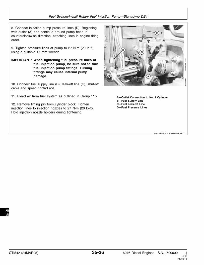
8. Connect injection pump pressure lines (D). Beginningwith outlet (A) and continue around pump head incounterclockwise direction, attaching lines in engine firingorder.
9. Tighten pressure lines at pump to 27 N·m (20 lb-ft),using a suitable 17 mm wrench.
IMPORTANT: When tightening fuel pressure lines atfuel injection pump, be sure not to turnfuel injection pump fittings. Turningfittings may cause internal pumpdamage.
10. Connect fuel supply line (B), leak-off line (C), shut-offcable and speed control rod.
11. Bleed air from fuel system as outlined in Group 115. A—Outlet Connection to No. 1 CylinderB—Fuel Supply LineC—Fuel Leak-off Line12. Remove timing pin from cylinder block. TightenD—Fuel Pressure Linesinjection lines to injection nozzles to 27 N·m (20 lb-ft).
Hold injection nozzle holders during tightening.
RG
6466
-U
N-2
6OC
T92
RG,CTM42,G35,90-19-14FEB95
Fuel System/Install Rotary Fuel Injection Pump—Stanadyne DB4
CTM42 (24MAR95) 35-36 6076 Diesel Engines—S.N. (500000— )160101
PN=313
3536

REMOVE FUEL INJECTION NOZZLES
General Nozzle Service Precautions:
1. Thoroughly clean area around injection pump andnozzles, including all line connections, using compressedair.
2. Cap or plug all fuel lines as they are disconnected toprevent dirt and debris from entering fuel system. Debrisin fuel system can plug injectors and cause enginedamage.
• On In-Line Injection Pumps:
3. Disconnect injection lines from injection pump usingJDF22 Crowsfoot Wrench.
IMPORTANT: On “P” injection pumps, JDE90Serrated Wrench (Robert Bosch) (B)and 22 mm Open End Wrench(Nippondenso) must be used to keepdelivery valve fittings stationary whileloosening line nuts. If a delivery valveand barrel housing rotates whileloosening or tightening a fuel line nut,injection pump delivery will be altered.Pump must be recalibrated on a test A—Fuel Injection Line Nutsstand. B—JDE90 Serrated Wrench
C—JDF22 Crowsfoot WrenchD—3/4 in. Line Wrench4. Remove fuel injection line nuts (A).
On Robert Bosch “P” injection pumps use JDE90Serrated Wrench with either JDF22 Crowsfoot Wrench(C) or a standard 3/4 in. Line Wrench (D).
On Nippondenso “P” injection pumps, use a 22 mmOpen End Wrench with either JDF22 Crowsfoot Wrenchor equivalent crowsfoot wrench mentioned above.
On “A” injection pumps, use either JDF22 CrowsfootWrench or an equivalent crowsfoot wrench.
RG
5877
-U
N-1
9AU
G91
RG
5878
-U
N-1
9AU
G91
RG,CTM42,G35,96-19-28OCT92
Fuel System/Remove Fuel Injection Nozzles
CTM42 (24MAR95) 35-37 6076 Diesel Engines—S.N. (500000— )160101
PN=314
3537

• On Rotary Pumps:
5. Disconnect shut-off cable and speed control rod.
6. Disconnect fuel leak-off line (A) and fuel supply line(B).
7. Using a suitable 17 mm deep-well crowsfoot socket,disconnect fuel delivery (pressure) lines (C).
A—Fuel Leak-off LinesB—Fuel Supply LineC—Fuel Pressure Lines
RG
6461
-U
N-2
6OC
T92
• On In-Line and Rotary Pumps:
8. Disconnect turbocharger oil line (A) at turbocharger.
9. Remove fuel delivery lines from injection nozzles. Liftinjection line assembly from engine.
10. Disconnect fuel leak-off line from injection nozzleleak-off connectors. Remove complete leak-off assembly.
RG
5323
-U
N-0
6DE
C88
11. Remove packing (C) and line nuts (B) from eachleak-off connector. Discard packing.
12. Remove leak-off connector (A) with O-ring from eachinjection nozzle.
RG
5756
-U
N-0
5AU
G91
RG,CTM42,G35,97-19-28OCT92
RG,CTM42,G35,49-19-28OCT92
RG,CTM42,G35,27-19-02OCT92
Fuel System/Remove Fuel Injection Nozzles
CTM42 (24MAR95) 35-38 6076 Diesel Engines—S.N. (500000— )160101
PN=315
3538

NOTE: The socket portion of JDE92 Nozzle Wrench (A)may be used to remove nozzles from cylinderhead.
13. If JDE92 Nozzle Wrench is not used, use a 24 mm(15/16 in.) deep socket on nozzle gland nut to removenozzles. Gland nut will act as a jack screw to raisenozzle out of cylinder head bore. Remove hardenedsteel washer from injection nozzle bore if it does notcome out with nozzle.
14. To prevent debris from entering combustion chamberafter nozzles are removed, insert a 12.7 mm (1/2 in.)hardwood dowel in nozzle bore. R
G57
57
-
UN
-05A
UG
91
RG,CTM42,G35,28-19-03OCT92
Fuel System/Remove Fuel Injection Nozzles
CTM42 (24MAR95) 35-39 6076 Diesel Engines—S.N. (500000— )160101
PN=316
3539

DIAGNOSE INJECTION NOZZLE MALFUNCTION
Problem Possible Cause Suggested Remedy
Failed Carbon Stop Seal Washer Nozzle replaced without using Install new seal or washer.new seal or washer.
Carbon stop seal groove not Clean groove. Install new seal.cleaned when new seal wasinstalled.
Incorrect Opening Pressure Improper adjustment. Adjust opening pressure.
Broken spring. Replace spring.
Nozzle Will Not Open Plugged orifices. Clean.
Chipped orifices. Replace nozzle.
Bottomed lift screw. Adjust lift screw.
Poor Spray Pattern Plugged orifices. Clean.
Chipped orifices. Replace nozzle.
Cracked nozzle tip. Replace nozzle.
Poor Atomization Plugged orifice. Clean.
Chipped orifice. Replace nozzle.
Cracked nozzle tip. Replace nozzle.
Valve not free. See “Inconsistent Chatter”.
Inconsistent Chatter Spring components misaligned. Adjust opening pressure.
Varnish on valve. Clean guide area.
Deposits in seat area. Clean seat.
Bent valve. Replace nozzle.
Distorted body. Replace nozzle.
S11,3010,NS -19-08APR94
Fuel System/Diagnose Injection Nozzle Malfunction
CTM42 (24MAR95) 35-40 6076 Diesel Engines—S.N. (500000— )160101
PN=317
3540

DIAGNOSE INJECTION NOZZLE MALFUNCTION—CONTINUED
Problem Possible Cause Suggested Remedy
No Chatter Spring components misaligned. Adjust opening pressure.
Varnish on valve. Clean guide area.
Deposits in seat area. Clean seat.
Bent valve. Replace nozzle.
Valve seat eroded or pitted. Lap valve to seat. Replacenozzle as necessary.
Tip seat pitted. Lap tip to seat. Replacenozzle as necessary.
Seat interference angle worn. Replace nozzle.
Distorted body. Replace nozzle.
Seat Leakage Deposits in seat area Clean seat.
Valve seat eroded or pitted. Lap valve to seat. Replacenozzle as necessary.
Tip seat pitted. Lap tip to seat. Replacenozzle as necessary.
Valve not free. See “Inconsistent Chatter”.See “No Chatter”.
Distorted body. Replace nozzle.
Cracked tip. Replace nozzle.
High Leak-Off Wear or Scratched at Guide Lap valve to guide. Replacenozzle.
Low Leak-Off Varnish on valve. Clean guide area.
Insufficient clearance. Clean nozzle. Lap valve to guide.Replace nozzle as necessary.
S11,3010,NT -19-13MAY93
Fuel System/Diagnose Injection Nozzle Malfunction
CTM42 (24MAR95) 35-41 6076 Diesel Engines—S.N. (500000— )160101
PN=318
3541

TEST FUEL INJECTION NOZZLES
Before disassembling, test injection nozzles with cleanfiltered fuel to determine its condition.
Test for:—Opening Pressure—Leakage—Chatter—Spray Pattern
N CAUTION: Nozzle tip should always be directedaway from operator. Fuel from spray orificescan penetrate skin and clothing, causingserious personal injury. Enclosing nozzle in atransparent cover, or glass beaker isrecommended.
Before applying pressure to nozzle tester, besure all connections are tight and fittings arenot damaged. Fuel escaping from a very smallhole can be almost invisible. Use a piece ofcardboard or wood; rather than your hands, tosearch for suspected leaks.
If ANY fluid is injected into the skin, it must besurgically removed within a few hours by adoctor familiar with this type injury organgrene may result.
X98
11
-UN
-23A
UG
88
S11,0408,AL -19-08APR94
Fuel System/Test Fuel Injection Nozzles
CTM42 (24MAR95) 35-42 6076 Diesel Engines—S.N. (500000— )160101
PN=319
3542
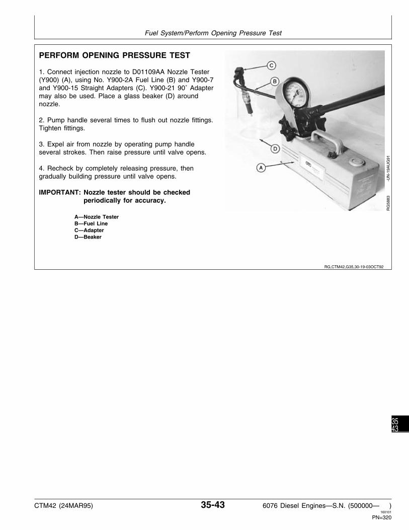
PERFORM OPENING PRESSURE TEST
1. Connect injection nozzle to D01109AA Nozzle Tester(Y900) (A), using No. Y900-2A Fuel Line (B) and Y900-7and Y900-15 Straight Adapters (C). Y900-21 90˚ Adaptermay also be used. Place a glass beaker (D) aroundnozzle.
2. Pump handle several times to flush out nozzle fittings.Tighten fittings.
3. Expel air from nozzle by operating pump handleseveral strokes. Then raise pressure until valve opens.
4. Recheck by completely releasing pressure, thengradually building pressure until valve opens.
IMPORTANT: Nozzle tester should be checkedperiodically for accuracy.
A—Nozzle TesterB—Fuel LineC—AdapterD—Beaker
RG
5883
-U
N-1
9AU
G91
RG,CTM42,G35,30-19-03OCT92
Fuel System/Perform Opening Pressure Test
CTM42 (24MAR95) 35-43 6076 Diesel Engines—S.N. (500000— )160101
PN=320
3543

INJECTION NOZZLE SPECIFICATIONS
A new nozzle or a used nozzle with a new spring (A),should open at approximately the following pressures. Aused nozzle that has been rebuilt with a new springand/or valve should be reset to same pressures as anew nozzle. New nozzle opening pressures are:
New Nozzle Opening Pressures(by nozzle tip size)**
7 x 0.22 mm, 7 x 0.23 mm,7 x 0.255 mm . . . . . . . . . . . . . 29 000—30 200 kPa (290—302 bar)
(4200—4370 psi)
On nozzles which have been in service, spring (A) andspring seat (B) will have taken a normal set. In thiscase, opening pressure is satisfactory if it meets orexceeds used nozzle minimum opening pressure givenbelow, but does not exceed new opening pressure givenabove. Used nozzle minimum opening pressures are:
Used Nozzle Minimum Opening Pressures(by nozzle tip size)**
7 x 0.22 mm, 7 x 0.23 mm,7 x 0.255 mm . . . . . . . . . . . . . . . 26 200 kPa (262 bar) (3800 psi)
Shims (C) of different thickness are available forchanging opening pressure adjustment. Each 0.05 mm(0.002 in.) of shim thickness changes opening pressureapproximately 700 kPa (7 bar) (100 psi).
IMPORTANT: ALWAYS use John Deere nozzleadjusting shims which are speciallyhardened. Other shims will not besatisfactory.
If nozzle opening pressures are not correct, disassembleinjection nozzles (as described in this group) and changeshims until nozzles open at proper new nozzle pressuregiven above. The difference in nozzle opening pressuresbetween cylinders in an engine should not exceed 350kPa (3.5 bar) (50 psi).
**See ASSEMBLE FUEL INJECTION NOZZLE later in this group fornozzle tip size identification.
RG
3410
-U
N-2
0DE
C88
RG,CTM42,G35,31-19-14FEB95
Fuel System/Injection Nozzle Specifications
CTM42 (24MAR95) 35-44 6076 Diesel Engines—S.N. (500000— )160101
PN=321
3544

PERFORM NOZZLE LEAKAGE TEST
A—Gland Nut O-Ring D—Shim G—Intermediate Plate I—NozzleB—Gland Nut E—Nozzle Valve Spring H—Nozzle Valve J—Nozzle Retaining NutC—Nozzle Holder F—Spring Seat
Nippondenso Nozzle (Bosch Similar)
1. Wipe nozzle dry.
2. Bring pressure up slowly to 1970 kPa (20 bar)(285 psi) below the opening pressure. Watch for anaccumulation of fuel from spray orifice, indicating abad seat.
If nozzle drips within 10 seconds, replace nozzlevalve (H) and nozzle (I).
3. Check for leakage around nozzle retaining nut (J)thread connection with nozzle holder (C).
Leakage indicates a bad seat either between nozzleand intermediate plate (G) or between nozzle holderand intermediate plate.
RG
5951
-U
N-3
0AU
G91
RG,CTM42,G35,32-19-03OCT92
Fuel System/Perform Nozzle Leakage Test
CTM42 (24MAR95) 35-45 6076 Diesel Engines—S.N. (500000— )160101
PN=322
3545

IMPORTANT: Do not lap the machined surfaces (A)of the intermediate plate in an attemptto stop fuel leakage at these locations.Dowels (spring pins) (B) in plate haveto be removed before surfaces can belapped. Removing dowels is notrecommended as removal is likely todamage them, and replacement dowelsare not available as service parts.
If leakage is observed, tighten nozzle retaining nut to amaximum of 79 N·m (58 lb-ft). Replace injection nozzle ifleakage continues.
RG2248 -UN-20APR89
PERFORM CHATTER AND SPRAY PATTERNTEST
1. Injection nozzle should chatter very softly, and onlywhen hand lever movement is very rapid (four to sixdownward movements per second). Failure to chattermay be caused by a binding or bent nozzle valve.
2. Until chattering range is reached, the test oil emergesas non-atomized streams. When lever movement isaccelerated, sprays should be very broad and finelyatomized.
A partially clogged or eroded orifice will usually causespray to deviate from the correct angle. Spray will alsobe steady rather than finely atomized.
3. Disassemble nozzle for cleaning or reconditioning if itfails to chatter or spray properly.
S11,0408,AP -19-08APR94
RG,CTM42,G35,33-19-03OCT92
Fuel System/Perform Chatter and Spray Pattern Test
CTM42 (24MAR95) 35-46 6076 Diesel Engines—S.N. (500000— )160101
PN=323
3546

DISASSEMBLE FUEL INJECTION NOZZLE
General Nozzle Repair Notes:
NOTE: Disassembly of nozzles is not recommendedunless servicing is indicated by nozzle operationand testing.
• Since dirt and water are the worst contaminants in fuelinjection system, working area, tools and cleaningmaterials must be kept spotlessly clean. Wheneverpossible, work in an isolated, dust-free area.
• Cover workbench with clean paper before disassemblyof injection nozzles.
• As parts are disassembled, place them in a pan ofclean diesel fuel and leave there until needed. Do notpermit parts to strike each other.
• Use a separate pan of clean diesel fuel for washingparts before assembly.
NOTE: Bosch KDEL and Nippondenso KDAL injectionnozzles are metric units. Only metric tools shouldbe used.
1. Use a 11 mm box or open-end wrench and unscrewleak-off connector (A) (if not removed previously) out ofnozzle holder (B).
2. Clamp flats of nozzle holder in a soft jawed vise.Remove nozzle retaining nut (C) from nozzle holderusing a 12-point 19mm wrench.
3. Slip gland nut (D) off nozzle holder.
NOTE: Bosch nozzles have a snap ring and O-ring at A—Leak-Off ConnectorB—Nozzle Holdertop of gland nut that must be removed beforeC—Nozzle Retaining Nutgland nut can be removed. After removing glandD—Gland Nut
nut, lower snap ring can be removed.
RG
5884
-U
N-1
9AU
G91
S11,0408,AR -19-08APR94
RG,CTM42,G35,50-19-03OCT92
Fuel System/Disassemble Fuel Injection Nozzle
CTM42 (24MAR95) 35-47 6076 Diesel Engines—S.N. (500000— )160101
PN=324
3547

A—Gland Nut O-Ring D—Shim G—Intermediate Plate I—NozzleB—Gland Nut E—Nozzle Valve Spring H—Nozzle Valve J—Nozzle Retaining NutC—Nozzle Holder F—Spring Seat
4. Remove nozzle assembly (H and I).
5. Pull off intermediate plate (G).
6. Remove spring seat (F), spring (E), and shims (D).
7. Remove gland nut O-ring (A).
8. Withdraw nozzle valve (H) from nozzle (I). If valveis stuck, it may be necessary to soak nozzleassembly in Bendix cleaner, acetone, or othercommercial cleaners sold especially for freeing stuckvalves.
N CAUTION: Use nozzle cleaning fluids inaccordance with manufacturer’sinstructions.
Do not permit lapped surfaces of valve and nozzle tocome in contact with any hard substance. DO NOTtouch valve unless your hands are wet with fuel.
RG
5951
-U
N-3
0AU
G91
RG,CTM42,G35,51-19-03OCT92
Fuel System/Disassemble Fuel Injection Nozzle
CTM42 (24MAR95) 35-48 6076 Diesel Engines—S.N. (500000— )160101
PN=325
3548
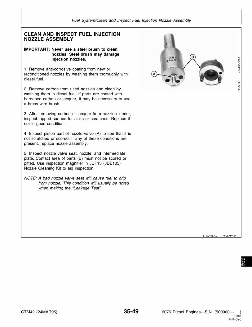
CLEAN AND INSPECT FUEL INJECTIONNOZZLE ASSEMBLY
IMPORTANT: Never use a steel brush to cleannozzles. Steel brush may damageinjection nozzles.
1. Remove anti-corrosive coating from new orreconditioned nozzles by washing them thoroughly withdiesel fuel.
2. Remove carbon from used nozzles and clean bywashing them in diesel fuel. If parts are coated withhardened carbon or lacquer, it may be necessary to usea brass wire brush.
3. After removing carbon or lacquer from nozzle exterior,inspect lapped surface for nicks or scratches. Replace ifnot in good condition.
4. Inspect piston part of nozzle valve (A) to see that it isnot scratched or scored. If any of these conditions arepresent, replace nozzle assembly.
5. Inspect nozzle valve seat, nozzle, and intermediateplate. Contact area of parts (B) must not be scored orpitted. Use inspection magnifier in JDF13 (JDE105)Nozzle Cleaning Kit to aid inspection.
NOTE: A bad nozzle valve seat will cause fuel to dripfrom nozzle. This condition will usually be notedwhen making the “Leakage Test”.
RG
3411
-U
N-2
0DE
C88
S11,0408,AU -19-08APR94
Fuel System/Clean and Inspect Fuel Injection Nozzle Assembly
CTM42 (24MAR95) 35-49 6076 Diesel Engines—S.N. (500000— )160101
PN=326
3549

PERFORM NOZZLE SLIDE TEST
NOTE: DO NOT touch lapped surface (D) unless handsare wet with diesel fuel.
1. Dip nozzle valve (A) in clean diesel fuel.
2. Insert valve in nozzle (B).
3. Hold nozzle vertical and pull valve out about one-thirdof its engaged length.
4. Release valve. Valve should slide down (C) to its seatby its own weight. Always replace a nozzle assembly ifvalve does not fall freely to its seat.
A—Nozzle ValveB—NozzleC—Free-Fall DistanceD—Lapped Surface
RG
5953
-U
N-3
0AU
G91
CLEAN SPRAY ORIFICES
1. Begin with cleaning wire (D) 0.07—0.10 mm(0.003—0.004 in.) from JDF13 (JDE105) Nozzle CleaningKit.
NOTE: Stoning wire to provide a flat surface on one sidewill help in reaming carbon from clogged hole.
2. Clamp cleaning wire in pin vise (A). Wire should notprotrude from vise more than 0.8 mm (1/32 in.).
3. Insert wire into orifice (C) and rotate.
4. For final cleaning, use cleaning wire 0.03 mm (0.001 A—Pin ViseB—Nozzlein.) smaller than orifice size. Follow previous steps untilC—Orificeorifices are clean of any carbon deposits.D—Cleaning Wire
RG
5954
-U
N-3
0AU
G91
RG,CTM42,G35,53-19-03OCT92
RG,CTM42,G35,54-19-05APR93
Fuel System/Clean Spray Orifices
CTM42 (24MAR95) 35-50 6076 Diesel Engines—S.N. (500000— )160101
PN=327
3550

INSPECT NOZZLE HOLDER
A—Lapped Surface C—M19 x 0.75 D—M6 x 1 E—M14 x 1.5B—Nozzle Holder
1. Inspect lapped surface (A) on bottom end ofnozzle holder (B) for nicks or scratches. Replaceholder if not in good condition.
2. Inspect threads M19 x 0.75 (C), M6 x 1 (D), andM14 x 1.5 (E) on nozzle holder for general condition.Threads that are nicked slightly may be “dressed-up.”Replace holder if threads cannot be restored to aserviceable condition.
3. Check fuel passages in nozzle holder to makesure they are open. Clean with compressed air.
4. Remove carbon deposits on both inner and outersurfaces of nozzle retaining nut.
5. Inspect retaining nut for cracks caused byovertightening or a damaged lower seating surface. Aseat may be restored by rubbing the surface withemery cloth. Any nozzle nut which cannot bereconditioned, must be replaced.
RG
5959
-U
N-3
0AU
G91
RG,CTM42,G35,55-19-03OCT92
Fuel System/Inspect Nozzle Holder
CTM42 (24MAR95) 35-51 6076 Diesel Engines—S.N. (500000— )160101
PN=328
3551

6. Examine lapped surfaces on intermediate plate (A) fornicks, scratches, or worn areas which would permit fuelto leak past.
7. Replace intermediate plate if lapped surfaces are wornor damaged.
IMPORTANT: Do not lap machined surfaces ofintermediate plate. Dowel pins (B) inplate have to be removed beforesurfaces can be lapped. Removingdowels is not recommended as removalis likely to damage them. Replacementdowels are not available as serviceparts.
8. Inspect spring seat for splitting, cracking, or excessivewear.
Replace seat if any of these conditions are evident.
RG2248 -UN-20APR89
RG2249 -UN-20APR89
RG,CTM42,G35,75-19-03OCT92
Fuel System/Inspect Nozzle Holder
CTM42 (24MAR95) 35-52 6076 Diesel Engines—S.N. (500000— )160101
PN=329
3552

9. Examine spring and shims for pitting or excessivewear.
Replace as necessary.
NOTE: The edge-type filter is pressed into nozzle holderand is not removable for service.
10. Clean filter by applying compressed air to nozzleholder fuel passage (A) at nozzle end.
RG
5955
-U
N-3
0AU
G91
RG
5962
-U
N-3
0AU
G91
INSPECT GLAND NUT
1. Inspect nozzle holder gland nut for general condition,be sure that it is not cracked or split.
2. Inspect M28 x 1.5 threads (A) for general condition.Threads which are slightly nicked or damaged may be“dressed up.”
Replace gland nut if unable to restore to a serviceablecondition.
RG
5956
-U
N-3
0AU
G91
RG,CTM42,G35,56-19-03OCT92
RG,CTM42,G35,57-19-05APR93
Fuel System/Inspect Gland Nut
CTM42 (24MAR95) 35-53 6076 Diesel Engines—S.N. (500000— )160101
PN=330
3553

3. Check passage in leak-off connector to see that it isopen.
4. Blow through connector passage with compressed air.
5. Inspect the M6 x 1 threads (A) for general condition.Replace connector if threads are damaged and cannotbe restored to a serviceable condition.
RG
5886
-U
N-1
9AU
G91
ASSEMBLE FUEL INJECTION NOZZLE
IMPORTANT: Be sure to install correct nozzleassembly on nozzle holder. Do notintermix different size nozzleassemblies.
To help determine correct nozzle assembly for eachapplication, note markings on lower part of nozzle.
The illustration shows a nozzle marked 7 x 0.255. Thenumber “7” (A) indicates the number of orifices and“0.255” (B) indicates the size of each orifice inmillimeters.
IMPORTANT: Immerse parts in clean fuel beforeassembly. DO NOT dry parts withtowels or compressed air. Dustparticles might collect and stay onpressure faces of nozzle valve andnozzle holder.
RG
5958
-U
N-3
0AU
G91
RG,CTM42,G35,34-19-03OCT92
RG,CTM42,G35,35-19-03OCT92
Fuel System/Assemble Fuel Injection Nozzle
CTM42 (24MAR95) 35-54 6076 Diesel Engines—S.N. (500000— )160101
PN=331
3554

1. Install a new O-ring (A) on nozzle holder.
2. Apply PT569 NEVER-SEEZ compound liberally toinside bore of gland nut to prevent gland nut fromseizing on holder body. Slide gland nut over nozzleholder until it bottoms against shoulder (B).
NOTE: Bosch nozzles have a snap ring toward bottomend that gland nut bottoms against, and anO-ring and snap ring at top end of gland nut tokeep it captive. Gland nut is installed from top ofnozzle holder on Bosch nozzles.
Nippondenso Shown (Bosch Similar)
RG
5960
-U
N-3
0AU
G91
3. Place shims (A), spring (B), and spring seat (C) innozzle holder (D) while still wet with diesel fuel.
NOTE: Make sure intermediate plate (E) is free of anyforeign material before reassembling.
A—ShimsB—SpringC—Spring SeatD—Nozzle HolderE—Intermediate Plate
RG
5957
-U
N-3
0AU
G91
4. Position intermediate plate (A) on nozzle holder (B).Dowel pins (C) in plate will permit installation only oneway.
5. Insert nozzle valve (D) into nozzle (E) while holdingparts below diesel fuel level in pan.
A—Intermediate PlateB—Nozzle HolderC—Dowel PinsD—Nozzle valveE—Nozzle
RG
5961
-U
N-3
0AU
G91
RG,CTM42,G35,58-19-03OCT92
RG,CTM42,G35,59-19-12SEP91
RG,CTM42,G35,36-19-03OCT92
Fuel System/Assemble Fuel Injection Nozzle
CTM42 (24MAR95) 35-55 6076 Diesel Engines—S.N. (500000— )160101
PN=332
3555

A—Gland Nut O-Ring D—Shim G—Intermediate Plate I—NozzleB—Gland Nut E—Nozzle Valve Spring H—Nozzle Valve J—Nozzle Retaining NutC—Nozzle Holder F—Spring Seat
Nippondenso Nozzle (Bosch Similar)
6. Install nozzle assembly on nozzle holder (C) andsecure with nozzle retaining nut (J).
7. Clamp nozzle holder in a soft-jawed vise. Tightennozzle retaining nut (12) to 60—79 N·m (44—58lb-ft).
8. Install leak-off connector on nozzle holder (C),using a new O-ring.
NOTE: Leak-off connector and O-ring should beinstalled on nozzle holder even though theywill have to be removed to install injectionnozzle in cylinder head. This will preventmisplacement of connector and O-ring beforeinstallation on engine.
RG
5951
-U
N-3
0AU
G91
RG,CTM42,G35,60-19-03OCT92
Fuel System/Assemble Fuel Injection Nozzle
CTM42 (24MAR95) 35-56 6076 Diesel Engines—S.N. (500000— )160101
PN=333
3556

ADJUST FUEL INJECTION NOZZLES
N CAUTION: Nozzle tip should always be directedaway from operator. Fuel from spray orificescan penetrate clothing and skin causingserious personal injury. Enclosing nozzle in aglass beaker is recommended.
Before applying pressure to nozzle tester, besure all connections are tight, and fittings arenot damaged. Fluid escaping from a very smallhole can be almost invisible. Use a piece ofcardboard or wood, rather than hands, tosearch for suspected leaks.
If ANY fluid is injected into the skin, it must besurgically removed within a few hours by adoctor familiar with this type injury organgrene may result.
1. Connect nozzle to nozzle tester, as directed earlier inthis group.
2. Refer to PERFORM OPENING PRESSURE TEST,earlier in this group, to test opening pressure of nozzle.Adjust as needed.
3. Refer to PERFORM NOZZLE LEAKAGE TEST, earlierin this group, to test for leakage.
4. Refer to PERFORM CHATTER AND SPRAYPATTERN TEST, earlier in this group, to test nozzleoverall operation.
X98
11
-UN
-23A
UG
88S11,3010,OE -19-30SEP94
Fuel System/Adjust Injection Nozzles
CTM42 (24MAR95) 35-57 6076 Diesel Engines—S.N. (500000— )160101
PN=334
3557

INSPECT AND CLEAN CYLINDER HEADNOZZLE BORE
1. Inspect condition of threads for gland nut. Threads aremetric (M28 x 1.5).
2. Inspect condition of nozzle seating surface in cylinderhead.
Cylinder head threads and nozzle seating surface mustbe free of debris and carbon deposits.
IMPORTANT: If injection nozzle gland nut threads arenot clean, a false torque wrenchreading may be obtained when injectionnozzle is installed. This may preventinjection nozzle from seating properlyin cylinder head.
3. Clean threads which have light foreign deposits usingan electric drill and D17030BR Thread Cleaning Brush.Work brush up and down several times to clean threads.
RG
5251
-U
N-1
4DE
C88
4. Clean threads with heavy foreign deposits or clean updamaged threads by using JDF5 Tap (M28 x 1.5 mm).Be sure to start tap straight to avoid possiblecross-threading. A light coat of grease on tap will helpcollect foreign deposits on tap and prevent them fromfalling into nozzle bore.
5. After cleaning threads, insert a 13 mm (1/2 in.)tapered hardwood dowel to plug nozzle tip bore.
6. Blow out debris from nozzle cavity with compressedair; then remove wood dowel.
R28
263N
-UN
-20D
EC
88
S55,3010,AU -19-03OCT92
RG,CTM42,G35,37-19-03OCT92
Fuel System/Inspect and Clean Cylinder Head Nozzle Bore
CTM42 (24MAR95) 35-58 6076 Diesel Engines—S.N. (500000— )160101
PN=335
3558

INSPECT AND CLEAN NOZZLE SEATINGSURFACE
1. Inspect nozzle seating surface for carbon deposits.
2. If seat is not clean, use the JDG609 Nozzle SeatReamer to remove carbon. Stop using tool when seatcomes clean.
3. Insert a 13 mm (1/2 in.) tapered hardwood dowel toplug the nozzle tip bore.
4. Blow out debris from nozzle cavity with compressedair; then remove wood dowel.
R26
860N
-UN
-20D
EC
88
INSTALL FUEL INJECTION NOZZLES
1. Apply PT569 NEVER-SEEZ compound to gland nutthreads and nozzle barrel (arrows). Be sure thatNEVER-SEEZ compound was also applied to inside boreof gland nut during assembly.
NOTE: Applying NEVER-SEEZ compound at theselocations will help prevent possible seizure ofgland nut to holder body.
2. Install a new R84472 Special Steel Washer (A) on tipend of assembled injection nozzle.
IMPORTANT: Do not intermix injection nozzles ofdifferent suppliers or different tip sizeswithin a single engine.
RG
5888
-U
N-1
9AU
G91
3. Insert injection nozzle into cylinder head. Turn glandnut by hand to make sure it is threaded straight incylinder head.
4. Use outer socket of JDE92 Nozzle Socket and turngland nut down to remove most of the looseness.
5. Rotate nozzle holder so hole for leak-off connectorthreads (A) are facing straight out from cylinder head.
RG
5889
-U
N-1
9AU
G91
RG,CTM42,G35,38-19-02OCT92
RG,CTM42,G35,39-19-03OCT92
RG,CTM42,G35,41-19-15SEP94
Fuel System/Install Fuel Injection Nozzles
CTM42 (24MAR95) 35-59 6076 Diesel Engines—S.N. (500000— )160101
PN=336
3559

6. Position inner socket (D) over nozzle holder andengage with flats at top of nozzle holder.
7. Place outer socket (C) portion of JDE92 NozzleSocket on gland nut with socket “window” (B) facingoutward.
8. Insert handle (A) through window into inner socket.Ball detent in handle will keep it secured to inner socket.
NOTE: Handle simulates position of leak-off connector,which must be square with engine to permitproper installation of leak-off lines.
A—HandleB—WindowC—Outer SocketD—Inner Socket
RG
5758
-U
N-0
5AU
G91
9. Tighten injection nozzle gland nut to 88 N·m (65 lb-ft).Keep handle (A) pointing straight out while tightening.
Socket window (B) is cut deep enough to obtain a new“bite” without removing inner socket.
10. Be sure O-ring is positioned against injection nozzlegland nut.
RG
5759
-U
N-0
5AU
G91
11. Install leak-off connectors (A) with O-rings oninjection nozzles. Tighten securely.
RG
5890
-U
N-1
9AU
G91
RG,CTM42,G35,42-19-15SEP94
RG,CTM42,G35,43-19-03OCT92
RG,CTM42,G35,44-19-10SEP91
Fuel System/Install Fuel Injection Nozzles
CTM42 (24MAR95) 35-60 6076 Diesel Engines—S.N. (500000— )160101
PN=337
3560

12. Loosen all leak-off line fittings (A), remove pipes (B),and inspect packings (C). Discard packings that are wornor cut.
NOTE: Mark each leak-off pipe before disassembly toassure assembly in correct location.
13. Check all pipes and fittings for wear or damage andreplace as necessary.
14. Reinstall new packings (if needed), and pipes intotee-fittings. Tighten all connections securely.
15. Install nuts (D) and packings onto leak-offconnectors. Install complete assembly over appropriateleak-off line connectors.
16. Tighten all leak-off line connections securely at eachinjection nozzle.
17. Connect leak-off line at injection pump (E) andtighten securely.
A—FittingsB—PipesC—PackingsD—NutsE—Pump Leak-off Line
RG
5091
-U
N-1
4DE
C88
RG
5880
-U
N-1
9AU
G91
RG,CTM42,G35,45-19-28OCT92
Fuel System/Install Fuel Injection Nozzles
CTM42 (24MAR95) 35-61 6076 Diesel Engines—S.N. (500000— )160101
PN=338
3561

IMPORTANT: Use JDE90 Serrated Wrench (B) onRobert Bosch “P” injection pumps, or a22 mm open end wrench onNippondenso “P” and all “A” pumps, tokeep delivery valve fittings stationarywhile tightening fuel line nuts. If adelivery valve and barrel housingrotates while tightening a fuel line nut,injection pump fuel delivery will bealtered, and pump will have to berecalibrated on a test stand.
18. Remove protective caps and plugs, that wereinstalled during disassembly, from injection lines, nozzlesand delivery valves. Install and connect injection lineassembly at each respective injection nozzle and deliveryvalve.
19. Tighten fuel injection line nozzle nuts (A) to 27 N·m(20 lb-ft).
20. Tighten line nuts at delivery valves to 27 N·m (20lb-ft) using JDF22 Crowsfoot Wrench (C) or a 3/4 in.Line Wrench (D) along with JDE90 Serrated Wrench (B)(Robert Bosch “P” Pumps) or a 22 mm open end wrench(all other pumps).
21. Bleed the fuel system. (See BLEED THE FUEL A—Fuel Injection Line NutsSYSTEM, in Group 115.) B—JDE90 Serrated Wrench
C—JDF22 Crowsfoot WrenchD—3/4 in. Line Wrench
RG
5877
-U
N-1
9AU
G91
RG
5878
-U
N-1
9AU
G91
RG,CTM42,G35,46-19-03OCT92
Fuel System/Install Fuel Injection Nozzles
CTM42 (24MAR95) 35-62 6076 Diesel Engines—S.N. (500000— )160101
PN=339
3562

EFFECTS OF ALTITUDE ANDTEMPERATURE ON ENGINEPERFORMANCE
Altitude, fuel temperature, air temperature, and humiditymay affect engine performance. As a general rule,atmospheric changes will usually cause a decrease inengine power by the percentages shown in chart below.
ATMOSPHERIC CHANGE % POWER DECREASE
Fuel Temperature Rise of 1˚C (1.8˚ F) above 40˚C (104˚F) . . . . . . . . . . . . . . . . . . . . . . . . . . . . 0.29
Air Temperature Rise of 5.5˚ C (10˚ F) above 25˚C (77˚F) . . . . . . . . . . . . . . . . . . . . . . . . . . . . . 0.50
Naturally Aspirated Engines: Altitude Rise of 300 m (1000 ft) above 183 m (600 ft) . . . . . . . . . . . . . . . . . . . . . . . . . . . 3.00**
Turbocharged Engines: Altitude Rise of 300 m (1000 ft) above 183 m (600 ft) . . . . . . . . . . . . . . . . . . . . . . . . . . . 0.50*
Relative Humidity Rise of 10% above 0% . . . . . . . . . . . . . . . . . . . . . . . . . . . . . . . . . . . 0.07
If engine required less fuel for acceptable performance athigher elevation, contact your local authorized fuelinjection pump repair station for service.
*Engine may have to be defueled when a substantial percentage ofoperating time occurs at 2250 m (7500 ft) or higher.
**Engine may have to be defueled when a substantial percentage ofoperating time occurs at 1500 m (5000 ft) or higher. RG,CTM42,G100,6-19-30SEP94
Group 100Engine Tune-Up and Break-In
CTM42 (24MAR95) 100-1 6076 Diesel Engines—S.N. (500000— )160101
PN=340
1001

PRELIMINARY ENGINE TESTING
Before tuning-up an engine, determine if a tune-upwill restore operating efficiency. If in doubt, thefollowing preliminary tests will help determine if theengine can be tuned-up. Choose from the followingprocedures only those necessary to restore the unit.
1. After engine has stopped for several hours, loosencrankcase drain plug and watch for any water to seepout. A few drops could be due to condensation, butany more than this would indicate problems whichrequire engine repairs rather than just a tune-up.
2. With engine stopped, inspect engine coolant for oilfilm. With engine running, inspect coolant for airbubbles. Either condition would indicate problemswhich require engine repairs rather than just atune-up.
3. Perform a dynamometer test and record poweroutput. See DYNAMOMETER TEST later in thisgroup. Repeat dynamometer test after tune-up.Compare power output before and after tune-up.
4. Perform compression test (See Group 105).
S11,22010,BW -19-08APR94
Engine Tune-Up and Break-In/Preliminary Engine Testing
CTM42 (24MAR95) 100-2 6076 Diesel Engines—S.N. (500000— )160101
PN=341
1002

GENERAL TUNE-UP RECOMMENDATIONS
The following services are recommended each time a tune-up is performed. Disregard those services that donot apply to any particular application.
Operation Detailed Reference
Check overall engine for fuel, lubricant, and coolant leaks.Repair leaks as necessary.
Change engine oil and filters. Operator’s Manual
Lubricate PTO clutch internal levers and linkage. Operator’s Manual
Replace fuel filter and water separator, if equipped. Group 35/Operator’s Manual
Clean crankcase ventilation assembly. This Group/Operator’s Manual
Replace air cleaner elements and check air intake system. This Group/Operator’s Manual
Check exhaust system. This Group
Check and service engine cooling system. This Group/Operator’s Manual
Check and adjust fan and alternator belts. Operator’s ManualReplace if necessary.
Check electrical system. This Group
Check crankshaft vibration damper. Group 15/Operator’s Manual
Inspect turbocharger and check turbocharger boost pressure. Group 110
Check fuel injection system: Check engine-to-injection pumptiming, clean injection nozzles, and adjust nozzle openingpressure. Group 35 and 115
Check engine oil pressure. Adjust if necessary. Group 105
Check engine valve clearance. Adjust if necessary. Group 05/Operator’s Manual
Check engine speeds. Adjust if necessary. Group 115
Check engine performance on dynamometer. Group 105
RG,CTM6,G100,2 -19-08APR94
Engine Tune-Up and Break-In/General Tune-Up Recommendations
CTM42 (24MAR95) 100-3 6076 Diesel Engines—S.N. (500000— )160101
PN=342
1003

DYNAMOMETER TEST
NOTE: High elevations may affect engine performance.See EFFECT OF ALTITUDE ANDTEMPERATURE ON ENGINE PERFORMANCE,earlier in this group.
1. Connect engine to dynamometer using manufacturer’sinstructions.
2. Operate engine at one-half load until coolant andcrankcase oil temperatures are up to normal.
3. Run engine at fast idle.
4. Gradually increase load on engine until speed isreduced to rated speed rpm.
NOTE: Refer to the appropriate machine technicalmanual for average power ratings of specificapplications, allow ±5% for minimum andmaximum power.
5. Read horsepower on dynamometer and recordreading.
6. Compare readings taken with power rating level foryour engine application.
RG,CTM86,G100,2-19-16SEP94
Engine Tune-Up and Break-In/Dynamometer Test
CTM42 (24MAR95) 100-4 6076 Diesel Engines—S.N. (500000— )160101
PN=343
1004

ENGINE BREAK-IN GUIDELINES
Engine break-in should be performed when the followingrepair have been made:
• Main bearings, rod bearings, crankshaft, or anycombination of these parts have been replaced.
• Pistons, rings, or liners have been replaced.
• Rear crankshaft oil seal and wear sleeve have beenreplaced. (Primary objective is to see if oil seal stillleaks).
• Cylinder head has been removed. Check and resetvalve clearance.
• Injection pump has been removed or criticaladjustments have been made while it is on the engine.(Primary objective is to check power).
RG,CTM61,G105,2-19-29SEP94
Engine Tune-Up and Break-In/Engine Break-In Guidelines
CTM42 (24MAR95) 100-5 6076 Diesel Engines—S.N. (500000— )160101
PN=344
1005

PERFORM ENGINE BREAK-IN
Use a dynamometer to perform the following break-inprocedure. If necessary, engine break-in can beperformed without a dynamometer if under controlledoperating conditions.
IMPORTANT: DO NOT use TORQ-GARD SUPREMEPLUS-50™ engine oil during break-inperiod of a new engine or enginethat has had a major overhaul.TORQ-GARD SUPREME PLUS-50 oilwill not allow a new or overhauledengine to properly wear during thisbreak-in period.
During break-in, periodically checkengine oil pressure and coolanttemperature. Also check for signs offuel, oil, or coolant leaks.
Fill engine crankcase with John Deere Break-In oil toproper level for use during the break-in operation.This oil is specifically formulated to enhanced break-inof John Deere diesel engines. Add John DeereBreak-In oil as needed to maintain the specified oillevel during break-in period.
ENGINE BREAK-IN AFTER MAJOR OVERHAUL
Time Load Engine Speed
5 Minutes No Load 850 rpm5 Minutes No Load 1500—2000 rpm5 Minutes 1/4 Load 1900—2100 rpm10 Minutes 1/2 Load 1900—2100 rpm10 Minutes 1/2—3/4 Load 1900—2100 rpm10 Minutes 3/4—Full Load Rated Speed
Check and readjust valve clearance as necessary.Cylinder head retorque is not required. (See Group05, Cylinder Head and Valves.)
Sufficiently load engine during the first 100 hours ofoperation, but, avoid over-loads, excessive idling, andextended no-load operation.
A second 100-hour service interval with John DeereEngine Break-In Oil may be required if the engine isoperated under light loads during the first 100-hourbreak-in period.
After 100 hours maximum, drain break-in oil andchange oil filter. Fill crankcase with John DeereTORQ-GARD SUPREME PLUS-50™ or otherheavy-duty diesel engine oil within the same serviceclassification as recommended in this manual. SeeDIESEL ENGINE OIL in Group 02, Fuels, Lubricants,and Coolant.
RG,CTM86,G100,5-19-26OCT94
Engine Tune-Up and Break-In/Perform Engine Break-In
CTM42 (24MAR95) 100-6 6076 Diesel Engines—S.N. (500000— )160101
PN=345
1006

CHECK CRANKCASE VENTILATION SYSTEM
1. Inspect crankcase ventilation system for restrictions.Lack of ventilation causes sludge to form in enginecrankcase. This can lead to clogging of oil passages,filters, and screens; resulting in serious engine damage.
2. Clean crankcase vent tube (A) with solvent andcompressed air if restricted. Install and tighten hoseclamps securely.
RG
5930
-U
N-2
0AU
G91
CHECK AIR INTAKE SYSTEM
1. Replace air cleaner primary filter element. Replacesecondary element if primary element has holes in it.
2. Check condition of air intake hose(s). Replace hosesthat are cracked, split, or otherwise in poor condition.
3. Check hose clamps (A) for tightness. Replace clampsthat cannot be properly tightened. This will help preventdust from entering the air intake system which couldcause serious engine damage. R
G46
89
-
UN
-20D
EC
88
RG,CTM42,G100,1-19-29OCT92
S11,22010,CU -19-08APR94
Engine Tune-Up and Break-In/Check Air Intake System
CTM42 (24MAR95) 100-7 6076 Diesel Engines—S.N. (500000— )160101
PN=346
1007

CHECK EXHAUST SYSTEM
1. Inspect exhaust system for leaks or restrictions. Checkmanifold for cracks. Repair or replace as necessary.
2. Check that turbocharger-to-exhaust elbow adapterclamps are securely tightened and do not leak.
3. Check exhaust stack for evidence of oil leakage pastvalve stem seals.
Oil in exhaust stack may be caused by excessive valvestem-to-guide clearance or excessive light load engineidling.
CHECK AND SERVICE COOLING SYSTEM
1. Remove trash that has accumulated on or nearradiator.
2. Visually inspect entire cooling system and allcomponents for leaks or damage. Repair or replace asnecessary.
3. Remove the foam filters from weep holes (A) locatedin the bottom of water pump housing. Inspect the weepholes for any restrictions.
4. Insert a heavy gauge wire deep into weep holes tomake sure holes are open.
5. Install new foam filters flush with pump housing ineach weep hole, if pump assembly passes inspection.
RG
5964
-U
N-0
5SE
P91
S55,22010,C -19-08APR94
RG,CTM42,G100,2-19-29OCT92
Engine Tune-Up and Break-In/Check and Service Cooling System
CTM42 (24MAR95) 100-8 6076 Diesel Engines—S.N. (500000— )160101
PN=347
1008

N CAUTION: Do not drain coolant until thecoolant temperature is below operatingtemperature. Always loosen water pump drainvalve (A) and block drain valve (B) slowly torelieve any excess pressure.
IMPORTANT: Both water pump drain valve and blockdrain valve must be opened tocompletely drain both sides of theengine.
6. Remove and check thermostats. See REMOVE ANDTEST THERMOSTATS in Group 25.
7. Drain and flush cooling system. See FLUSHING ANDSERVICING COOLING SYSTEM in Group 02.
IMPORTANT: Air must be expelled from coolingsystem when system is refilled. Loosentemperature sending unit fitting at rearof cylinder head, bleed plug or petcockat top front of cylinder head, or plug inthermostat housing to allow air toexcape when filling system. Retightenfitting or plug when all the air has beenexpelled.
8. Fill cooling system with coolant. Followrecommendations in Group 02.
9. Run engine until it reaches operating temperature.Check entire cooling system for leaks.
10. After engine cools, check coolant level.
NOTE: Coolant level should be approximately 19 mm(3/4 in.) below bottom of radiator filler neck.
11. Check system for holding pressure. See PRESSURETEST COOLING SYSTEM AND RADIATOR CAP inGroup 105.
TS
281
-U
N-2
3AU
G88
RG
5836
-U
N-2
8AU
G91
RG,CTM42,G100,3-19-29OCT92
Engine Tune-Up and Break-In/Check and Service Cooling System
CTM42 (24MAR95) 100-9 6076 Diesel Engines—S.N. (500000— )160101
PN=348
1009

CHECK ELECTRICAL SYSTEM
N CAUTION: Battery gas can explode. Keepsparks and flames away from batteries. Use aflashlight to check battery electrolyte level.
Never check battery charge by placing a metalobject across the posts. Use a voltmeter orhydrometer.
Always remove grounded (-) battery clamp firstand replace it last.
1. Clean batteries, and cables with a damp cloth. Ifcorrosion is present, remove it and wash the terminalswith a solution of ammonia or baking soda in water.Then flush area with clean water.
2. Coat battery terminals and connectors with petroleumjelly mixed with baking soda to retard corrosion.
3. Test batteries. If batteries are not near full charge, tryto find out why.
4. On low-maintenance batteries, check level ofelectrolyte in each cell of each battery. Level should beto bottom of filler neck. If water is needed, use clean,mineral-free water.
If water must be added to batteries more often thanevery 250 hours, alternator may be overcharging.
NOTE: Water cannot be added to maintenance-freebatteries.
5. If batteries appear to be either undercharged orovercharged, check alternator and charging circuit.
6. Check tension of fan belts. See operator’s manual.
7. Check operation of starting motor and gauges.T
S20
4
-
UN
-23A
UG
88
S11,22010,CZ -19-16SEP94
Engine Tune-Up and Break-In/Check Electrical System
CTM42 (24MAR95) 100-10 6076 Diesel Engines—S.N. (500000— )160101
PN=349
10010

SPECIAL OR ESSENTIAL TOOLS
NOTE: Order tools according to information given in theU.S. SERVICE-GARD™ Catalog or in theEuropean Microfiche Tool Catalog (MTC).
Compression Test Kit . . . . . . . . JT01674 (D14546BA)
A—Gauge and Hose Assembly JT01682 (D14547BA)
B—Nozzle Adapter . . . . . . . . JT01675A (D14557BA)
C—Adapter Nut . . . . . . . . . . . . . . . . . . . . JT01677
Used to test each cylinder’s compression pressure.
RG
5784
-U
N-0
9AU
G91
Oil Galley Plug Tool . . . . . . . . . . . . . . . . . . JDG782
Used to remove and install oil galley plug.
RG
6612
-U
N-2
9JA
N93
Nozzle Socket . . . . . . . . . . . . . . . . . . . . . . . JDE92
Used to remove and install fuel injection nozzles.
R28
362N
-UN
-20D
EC
88
Universal Pressure Test Kit . . . . JT05470 (D15027NU)
Used for testing engine oil pressure.
RG5162 -UN-23AUG88
DX,TOOLS -19-05JUN91
RG,JT01674 -19-17SEP91
RG,JDG782 -19-02APR93
S11,22005,R -19-16AUG94
S55,22005,B -19-17SEP91
Group 105Engine System Operation and Test
CTM42 (24MAR95) 105-1 6076 Diesel Engines—S.N. (500000— )160101
PN=350
1051

Flywheel Turning Tool . . . . . . . . . . . . . . . . . JDG820
Used to rotate engine to check damper radial runout andtime engine. JDE81-1 may be used also if JDG820 isnot available.
RG
7056
-U
N-1
0AU
G94
Timing Pin . . . . . . . . . . . . . . . . . . . . . . . . . JDE81-4
Lock engine at TDC when timing valve train.
RG5068 -UN-23AUG88
Cooling System Pressure Pump . . . . . . . . D05104ST
Used to pressure test radiator cap and cooling system.
R26
406N
-UN
-29N
OV
88
RG,JDG820 -19-14FEB95
S53,JDE814A -19-08AUG94
S55,22005,C -19-17SEP91
Engine System Operation and Test/Special or Essential Tools
CTM42 (24MAR95) 105-2 6076 Diesel Engines—S.N. (500000— )160101
PN=351
1052

ENGINE TEST SPECIFICATIONS
ITEM SPECIFICATION
Compression Pressure: (at 275—325 RPM cranking speed) . . . . . . . . . . . . 2380—2790 kPa (23.8—27.9 bar) (345—405 psi) Maximum Variation between cylinders . . . . . . . . . . 340 kPa (3.4 bar) (50 psi)
Oil Pressure at 115˚C (240˚F): Minimum No Load at 850 rpm (Slow Idle) . . . . . . . 138 kPa (1.4 bar) (20 psi) Maximum Full Load at 1800—2200 rpm Rated Speed) . . . . . . . . . . . . . . . . . . . . . . . . 400 kPa (4.0 bar) (58 psi)
Cooling System Leakage Test Pressure . . . . . . . . . 50 kPa (0.5 bar) (7 psi)
RG,CTM42,G105,1-19-16AUG94
Engine System Operation and Test/Engine Test Specifications
CTM42 (24MAR95) 105-3 6076 Diesel Engines—S.N. (500000— )160101
PN=352
1053

ENGINE—SECTIONAL VIEW
A—Rocker Arm Shaft F—Cylinder Block K—Liner Packing Rings P—ValveB—Cylinder Head G—Crankshaft L—Cylinder Liner Q—Fuel Injection NozzleC—Push Rod H—Crankshaft Counterweight M—Piston R—Valve springD—Cam Follower I—Oil Pan N—Piston Pin S—Rocker ArmE—Camshaft J—Connecting Rod O—Piston Rings T—Oil Pump
RG
5805
-U
N-1
2AU
G91
RG,CTM42,G1,6 -19-20AUG91
Engine System Operation and Test/Engine—Sectional View
CTM42 (24MAR95) 105-4 6076 Diesel Engines—S.N. (500000— )160101
PN=353
1054

GENERAL ENGINE DESCRIPTION
All 6076 Engines are vertical stroke, in-line,valve-in-head, 6-cylinder diesel engines. The cylinderfiring order is 1-5-3-6-2-4.
On 6076 Engines, direct fuel injection is provided byan in-line injection pump and 21 mm injection nozzlesmounted in cylinder head. The pump is driven by anintermediate gear in the timing gear train meshingwith the camshaft gear.
The pump has an engine-driven camshaft whichrotates at one-half engine speed. Roller camfollowers, riding on the camshaft lobes, operate theplungers to supply high-pressure fuel through thedelivery valves to the injection nozzles. Agovernor-operated control rack is connected to thecontrol sleeves and plungers to regulate the quantityof fuel delivered to the engine.
All engines are turbocharged. Operated by exhaustgases, the turbocharger compresses intake air fromair cleaner and routes it to each cylinder’scombustion chamber.
An air-to-air aftercooler cools the turbochargercompressor discharge air by routing it through a heatexchanger (usually mounted in front of radiator)before it enters the intake manifold. The heatexchanger uses no liquid coolant, but relies on airflow to cool the charge air.
The camshaft and followers are made of chilled iron.The cam lobes are individually flame hardened toprovide excellent wear characteristics. Sphericallyground followers riding on tapered cam lobes helpinsure positive follower rotation.
Intake and exhaust valves are operated by camfollowers, push rods, and rocker arm assembly.Cylinder heads have replaceable inserts and valves,and have positive rotators for both intake and exhaustvalves.
The crankshaft is a one-piece, heat treated,dynamically balanced steel forging which rotates inreplaceable two-piece main bearings. The rear thrustbearing has a flange on each side to reducecrankshaft deflection and to limit end play during highload operation.
Cylinder liners are of a wet sleeve, flanged, andcentrifugally cast design. O-rings are used to seal theconnection between cylinder block and liners. Linersare induction hardened and are individuallyreplaceable.
Pistons are constructed of high-grade cast aluminumalloy and are cam ground. A double Ni-Resist ringcarrier is cast integrally in the piston to greatlyimprove the life of the two ring grooves. A deepcombustion chamber design provides maximumcombustion efficiency. Pistons have a three ringcombination. The top two rings are compression ringsand the lower ring is an oil control ring.
The highly polished, hardened piston pins arefully-floating and held in position by means of snaprings. Spray jets (piston cooling orifices) in cylinderblock direct pressure oil to lubricate piston pins andcool pistons.
Connecting rods are of forged steel and havereplaceable bushing and bearing inserts. They areweight controlled (by machining) on both ends tominimize engine vibration.
The engine is supplied with lubricating oil by a spurgear pump driven off the rear of the crankshaft. Oil isconditioned in a housing located on the right side ofthe engine. Oil temperature is limited by an oil coolerand filtered by a full flow oil filter. Individual coolerand filter bypass valves protect the system andensure engine lubrication during times of highrestriction; such as cold starts. Oil pressure iscontrolled by a pressure regulating valve locatedbefore the gallery.
RG,CTM42,G1,5 -19-29OCT92
Engine System Operation and Test/General Engine Description
CTM42 (24MAR95) 105-5 6076 Diesel Engines—S.N. (500000— )160101
PN=354
1055

HOW THE LUBRICATION SYSTEM WORKS
NOTE: Refer to illustration on following page. Aseparate illustration of the oil conditioninghousing assembly is found later in this group.
The engine lubrication system consists of agear-driven (crankshaft), positive displacement pump(O), oil cooler (A), oil filter (C), cooler bypass valve(B), filter bypass valve (D), and oil pressureregulating valve (E).
Oil is drawn up from the oil pan through the oil pump.After it leaves the oil pump, oil flows to the oil coolerthrough a machined passage in the cylinder block.The oil conditioning housing (V) contains the oilcooler bypass valve, oil filter bypass valve, oilpressure regulating valve, and the engine oil filter. Oilthen proceeds through the oil cooler where itexchanges heat with the coolant.
If high restriction is sensed, such as during a coldstart, oil bypasses the oil cooler through the coolerbypass valve and goes directly to the oil filter. Ifexcessively high restriction is sensed at the filter, oilis diverted directly to the regulating valve. Afterflowing past the regulating valve; pressurized, cooledclean oil is supplied to the main oil gallery. Oil is thendistributed, under pressure, to each main bearing (F)and piston cooling orifice (I). Oil from the pistoncooling orifices lubricates the piston pin and bushing(J) through a hole in the top of the connecting rod.The regulating valve permits excess oil to be divertedback to the oil pan.
From the main oil gallery, cooled clean oil is pressurefed to the main and rod bearings (G), piston coolingorifices, and camshaft bushings (H). Oil from the frontcamshaft bushing is fed through a drilled hole in thecamshaft nose and lubricates the camshaft thrustwasher and splash lubes the front gears. Theinjection pump is pressure lubed off of the maingallery.
Oil from the rear camshaft bushing is fed through adrilling in the cylinder block and cylinder head and upto the rocker arm shaft. Oil from the shaft isdistributed to the rocker arms. Oil from the rockerarms lubricates the other valve train components andcamshaft followers.
Clean oil from the oil filter goes to the turbochargeroil inlet line (K) and is returned through theturbocharger oil return tube (L). Oil completes thecircuit by returning to the oil pan.
CTM42,G105,20 -19-29OCT92
Engine System Operation and Test/How the Lubrication System Works
CTM42 (24MAR95) 105-6 6076 Diesel Engines—S.N. (500000— )160101
PN=355
1056

HOW THE LUBRICATION SYSTEM WORKS—CONTINUED
A—Engine Oil Cooler G—Connecting Rod Bearings L—Turbocharger Oil Return Q—To Oil Cooler*B—Oil Cooler Bypass Valve H—Camshaft Bushings Tube* R—From Oil Pump*C—Oil Filter I—Piston Cooling Orifices M—High Pressure Engine Oil S—To Main Oil Gallery*D—Filter Bypass Valve J—Piston Pin and Bushing N—Low Pressure Engine Oil T—To Oil Pan*E—Oil Pressure Regulating K—Turbocharger Oil Inlet O—Engine Oil Pump U—To Turbocharger*
Valve Line P—From Oil Cooler* V—Oil Conditioning Housing*F—Main Bearings
*Not shown on this artwork, refer to artwork later in this group.
RG
C64
21
-U
N-
CTM42,G105,21 -19-29OCT92
Engine System Operation and Test/How the Lubrication System Works
CTM42 (24MAR95) 105-7 6076 Diesel Engines—S.N. (500000— )160101
PN=356
1057

HOW THE LUBRICATION SYSTEM WORKS—CONTINUED
A—Engine Oil Cooler* G—Connecting Rod L—Turbocharger Oil Return Q—To Oil CoolerB—Oil Cooler Bypass Valve Bearings* Tube* R—From Oil PumpC—Oil Filter H—Camshaft Bushings* M—High Pressure Engine Oil S—To Main Oil GalleryD—Filter Bypass Valve I—Piston Cooling Orifices* N—Low Pressure Engine Oil T—To Oil PanE—Oil Pressure Regulating J—Piston Pin and Bushing* O—Engine Oil Pump* U—To Turbocharger
Valve K—Turbocharger Oil Inlet P—From Oil Cooler V—Oil Conditioning HousingF—Main Bearings* Line*
*Not shown on artwork on following page. Refer to artwork earlier inthis group. CTM42,G105,22 -19-29OCT92
Engine System Operation and Test/How the Lubrication System Works
CTM42 (24MAR95) 105-8 6076 Diesel Engines—S.N. (500000— )160101
PN=357
1058
HOW THE LUBRICATION SYSTEM WORKS—CONTINUED
Oil Conditioning Assembly
RG
C64
22
-U
N-
CTM42,G105,23 -19-30APR93
Engine System Operation and Test/How the Lubrication System Works
CTM42 (24MAR95) 105-9 6076 Diesel Engines—S.N. (500000— )160101
PN=358
1059

HOW THE COOLING SYSTEM WORKS
Refer to illustration on the following page.
The pressurized cooling system consists of aconventional radiator (A), water pump (C),thermostats (H), and water outlet manifold (G).
The pump draws low temperature coolant from thebottom of the radiator and discharges it through thewater inlet manifold elbow (D), into the main coolantgallery (E) on the right-hand side of the engine.Coolant from the main coolant gallery flows into thelower end of the engine oil cooler cavity (F),circulates around the oil cooler plates to cool theengine oil, and then flows out the upper end of the oilcooler cavity and into the cylinder block coolantjacket.
Coolant enters the coolant jacket near the rear of theengine, and flows around the cylinder linersprogressing upward toward the cylinder head andforward from No. 6 cylinder toward No. 1 cylinder. Asthe coolant circulates around the cylinder liners, itcarries excess heat away from the liners.
The coolant then flows through the block deckpassages and cylinder head gasket into the cylinderhead. Coolant passages in the block deck, cylinderhead gasket, and cylinder head are sized to provideeven coolant flow in all parts of the cylinder head.Upon entering the cylinder head, the coolantcirculates through cavities around intake and exhaustports, injector bores, valve guides and valve seats tokeep all parts of the head at acceptable temperaturelevels.
The coolant flows toward the front end of the cylinderhead where it passes through the outlet cavity andinto the water outlet manifold (G) and thermostathousing.
If the coolant temperature in the thermostat housingis below the thermostat opening temperature,thermostats will remain closed (as during warm-upperiods), causing coolant to be directed back throughthe bypass pipe (B) and into the water pump inlet tobe recirculated through the engine. This provides afaster and more uniform warm-up.
If the coolant temperature in the thermostat housingis above the thermostat opening temperature,thermostats will be open (engine is at normaloperating temperature) and coolant will flow throughthe thermostats into the thermostat cover and on tothe radiator top tank to be cooled.
On 6076A engines, coolant is taken from the upperleft cylinder block and routed into the aftercooler (I)where it circulates through the aftercooler core andback out to the thermostat housing. Coolantcirculating through the aftercooler absorbs heat fromthe pressurized intake air and carries the heat backto the engine cooling system to be dissipated throughthe radiator.
Two locations are provided for draining the coolantout of the engine. The block drain valve (J) is locatedin the center of the left-hand side of the cylinderblock, and is used to drain the left side of the engine.The water pump drain valve (K) is located on thebottom rear of the water pump, and is used to drainthe right side of the engine (water pump, oil cooler,main coolant gallery).
CTM42,G105,24 -19-29OCT92
Engine System Operation and Test/How the Cooling System Works
CTM42 (24MAR95) 105-10 6076 Diesel Engines—S.N. (500000— )160101
PN=359
10510

HOW THE COOLING SYSTEM WORKS—CONTINUED
A—Radiator E—Main Coolant Gallery I—Aftercooler (’A’ Engines) M—High Temperature EngineB—Coolant Bypass Pipe F—Engine Oil Cooler J—Block Drain Valve CoolantC—Water Pump G—Water Outlet Manifold K—Water Pump Drain ValveD—Water Inlet Manifold H—Thermostats (2 used) L—Low Temperature Engine
Elbow Coolant
CTM42,G105,25 -19-29OCT92
Engine System Operation and Test/How the Cooling System Works
CTM42 (24MAR95) 105-11 6076 Diesel Engines—S.N. (500000— )160101
PN=360
10511

HEAD GASKET JOINT CONSTRUCTION AND OPERATION
A—Cylinder Head C—Dowel Pins F—Gasket Body H—Stainless Steel FlangeB—Cylinder Head Cap D—Cylinder Liners G—Fire Ring Combustion
Screws E—Cylinder Block Seal
The head gasket joint consists of:
• Cylinder head gasket• Cylinder head (A)• Cylinder block (E)• Cylinder liners (C)• Cylinder head cap screws (B)
RG
6430
-U
N-1
7SE
P92
RG
6447
-U
N-1
3OC
T92
CTM42,G105,15 -19-08APR94
Engine System Operation and Test/Head Gasket Joint Construction and Operation
CTM42 (24MAR95) 105-12 6076 Diesel Engines—S.N. (500000— )160101
PN=361
10512

Refer to illustration on previous page.
The head gasket must form an air-tight seal betweencylinder liners and cylinder head that can withstandthe temperatures and pressures of the combustionprocess. The gasket must also form a liquid-tight sealbetween the cylinder head and cylinder block toretain coolant and oil in their respective passages.The gasket is constructed of thin, formed sheets ofsteel-inserted, non-asbestos material (F). The surfaceof gasket is treated to improve liquid sealing andanti-stick characteristics. A fire ring combustion seal(G) is located at each cylinder bore and is held inplace by a U-shaped stainless steel flange (H).
The cylinder head and block must be flat to providean even clamping pressure over the entire surface ofgasket, and must have the proper surface finish tokeep gasket material from moving in the joint. Dowels(D) are used to properly locate head gasket on block.
The cylinder liners must protrude evenly from top ofcylinder block the specified amount to provideadequate clamping force on fire ring of each cylinder.
The cap screws must be proper length, made ofproper material, and be tightened to proper torque inorder to provide an adequate clamp load betweenother joint components.
Each of the above components contributes to theintegrity of the head gasket joint. If any of thesecomponents do not conform to specifications, gasketjoint may fail resulting in combustion leaks, coolantleaks, or oil leaks.
Operating conditions such as coolant, oil, andcombustion temperatures, and combustion pressurescan reduce the ability of the head gasket joint tofunction properly. Failure of head gasket and matingparts may occur when coolant and oil temperaturesbecome excessive, or when abnormally highcombustion temperatures and pressures persist.
CTM42,G105,26 -19-29OCT92
Engine System Operation and Test/Head Gasket Joint Construction and Operation
CTM42 (24MAR95) 105-13 6076 Diesel Engines—S.N. (500000— )160101
PN=362
10513

DIAGNOSING HEAD GASKET JOINTFAILURES
Head gasket failures generally fall into three categories:
• Combustion seal leakage.• Coolant seal leakage.• Oil seal leakage.
Combustion seal leakage failures occur when combustiongases escape between cylinder head and head gasketcombustion flange, or between combustion flange andcylinder liner. Leaking combustion gases may vent to anadjacent cylinder, to a coolant or oil passage, orexternally.
Coolant or oil seal leakage failures occur when oil orcoolant escapes between cylinder head and gasket body,or between cylinder block and gasket body. The oil orcoolant may leak to an adjacent coolant or oil passage,or externally. Since oil and coolant passages areprimarily on right hand (camshaft) side of engine, fluidleaks are most likely to occur in that area.
Follow these diagnostic procedures when a head gasketjoint failure occurs, or is suspected.
1. Before starting or disassembling engine, conduct avisual inspection of machine, and note any of the
A—Combustion Sealing Areasfollowing: B—Oil Sealing Areas (Push Rod)
C—Coolant Sealing AreasD—Cylinder Head Cap Screws • Oil or coolant in head gasket seam, or on adjacent
surfaces. Especially right rear corner of gasket joint. • Displacement of gasket from normal position. • Discoloration or soot from combustion gas leakage. • Leaking radiator, overflow tank, or hoses. • Leaking coolant from water pump weep hole. • Damaged or incorrect radiator, fan, or shroud. • Obstructed air flow or coolant flow. • Worn or slipping belts. • Damaged or incorrect pressure cap. • Presence of oil in coolant. • Low coolant levels. • Improper coolant. • Unusually high or low oil levels. • Oil degradation, dilution, or contamination. • Correctly specified injection pump. • Indications of fuel or timing adjustments. • Unburned fuel or coolant in exhaust system.
RG
6449
-U
N-1
3OC
T92
CTM42,G105,16 -19-08APR94
Engine System Operation and Test/Diagnosing Head Gasket Joint Failures
CTM42 (24MAR95) 105-14 6076 Diesel Engines—S.N. (500000— )160101
PN=363
10514

2. Obtain coolant and oil samples for further analysis.
3. Start and warm up engine if it can be safelyoperated. Examine all potential leakage areas againas outlined previously. Using appropriate test andmeasurement equipment, check for the following:
• White smoke, excessive raw fuel, or moisture in exhaust system. • Rough, irregular exhaust sound, or misfiring. • Air bubbles, gas entrainment in radiator or overflow tank. • Loss of coolant from overflow. • Excessive cooling system pressure. • Coolant overheating. • Low coolant flow. • Loss of cab heating (air lock).
4. Shut engine down. Recheck crankcase, radiator,and overflow tank for any significant differences influid levels, viscosity, or appearance.
5. Compare your observations from above steps withthe following diagnostic charts. If diagnosticevaluations and observations provide conclusiveevidence of combustion gas, coolant, or oil leakagefrom head gasket joint, the cylinder head must beremoved for inspection and repair of gasket jointcomponents.
Combustion Seal Leakage
Symptoms: Possible Causes:
• Exhaust from head gasket crevice • Insufficient liner standout• Air bubbles in radiator/overflow tank • Excessive liner standout differential between cylinders• Coolant discharge from overflow tube • Low head bolt clamping loads• Engine overheating • Rough/damaged liner flange surface• Power loss • Cracked/deformed gasket combustion flange• Engine runs rough • Out-of-flat/damaged/rough cylinder head surface• White exhaust smoke • Missing/mislocated gasket fire ring• Loss of cab heat • Block cracked in liner support area• Gasket section dislodged, missing (blown) • Excessive fuel delivery• Coolant in cylinder • Advanced injection pump timing• Coolant in crankcase oil • Hydraulic or mechanical disturbance of combustion seal• Low coolant level
NOTE: Cracked cylinder head or liners may also allow combustion gas leakage into coolant.
RG,CTM8,G105,11-19-29OCT92
RG,CTM8,G105,12-19-16SEP92
Engine System Operation and Test/Diagnosing Head Gasket Joint Failures
CTM42 (24MAR95) 105-15 6076 Diesel Engines—S.N. (500000— )160101
PN=364
10515

Coolant Seal Leakage
Symptoms: Possible Causes:
• Coolant discharge from head gasket crevice • Excessive liner standout• Coolant in crankcase oil • Excessive liner standout differential between cylinders• Low coolant level • Low head bolt clamping loads• High oil level • Out-of-flat/damaged/rough block surface• Coolant discharge from crankcase vent • Out-of-flat/damaged/rough cylinder head surface
• Oil or coolant overheating• Cracks/creases in gasket body surfaces• Damage/voids in elastomer beading
NOTE: Cracked cylinder head, liners, liner packings, defective oil cooler or aftercooler may also allow coolant leakage into crankcase.
Oil Seal Leakage
Symptoms: Possible Causes:
• Oil discharge from head gasket crevice • Excessive liner standout• Oil in coolant • Excessive liner standout differential between cylinders• Low crankcase oil level • Low head bolt clamping loads• Reduced oil to rocker arms (noisy) • Out-of-flat/damaged/rough block surface
• Out-of-flat/damaged/rough cylinder head surface• Oil or coolant overheating• Cracks/creases in gasket body surfaces• Damage/voids in elastomer beading• Damaged/missing O-ring seal at oil port to rocker arms
NOTE: Defective oil cooler may also allow oil leakage into coolant.
RG,CTM8,G105,13-19-13MAY93
RG,CTM8,G105,14-19-16SEP92
Engine System Operation and Test/Diagnosing Head Gasket Joint Failures
CTM42 (24MAR95) 105-16 6076 Diesel Engines—S.N. (500000— )160101
PN=365
10516

HEAD GASKET INSPECTION AND REPAIR SEQUENCE
A—Combustion Seals B—Gasket Body D—Elastomer Beading Strips E—Front of Engine(Flanges) C—Rocker Arm Oil Port
The following inspection procedures arerecommended whenever a head gasket joint failureoccurs, or when joint disassembly takes place.
1. Review historical data relating to machineoperation, maintenance and repair, along withdiagnostic observations. Note all areas requiringfurther inspection and analysis.
2. Remove rocker arm cover and check for presenceof coolant in the oil.
3. Record head cap screw torques prior to removal.Upon removal, check cap screw length differences.
4. Remove cylinder head using appropriate liftingdevices to prevent handling damage to head gasket.See REMOVE CYLINDER HEAD in Group 05.
5. Observe surfaces of removed head gasket.
Examine combustion seals (A) for the following: • Flange severed/expanded/cracked/deformed. • Adjacent body area burned/eroded. • Fire ring severed/displaced/missing. • Flange sealing pattern eccentric/contains voids. • Discoloration of flange and adjacent body areas. • Flange surfaces rough/abraided/channelled.
Examine gasket body (B) for the following: • Combustion gas erosion paths or soot deposits originating at combustion seals. • Extreme discoloration/hardening/embrittlement in localized areas. • O-ring seal missing/damaged in port area (C). • Elastomer missing/damaged in port areas (D). • Oil or coolant paths from port areas. • Localized areas of low compression.
6. Before cleaning components, inspect head, block,and liners for evidence of combustion gas and fluidleakage. Inspect cylinders and valve ports for unusualdeposits.
RG
6448
-U
N-1
3OC
T92
CTM42,G105,17 -19-08APR94
Engine System Operation and Test/Head Gasket Inspection and Repair Sequence **M:CTM42,G105,18 -19-
CTM42 (24MAR95) 105-17 6076 Diesel Engines—S.N. (500000— )160101
PN=366
10517

DIAGNOSING ENGINE MALFUNCTIONS
• Will Not Crank:
Electrical System Malfunction Weak battery Corroded or loose battery connections Defective main switch or start safety switch Starter solenoid defective Starter defective
• Hard to Start or Will Not Start:
Electrical System Malfunction Loose or corroded battery connections Weak battery Excessive resistance in starter circuitFuel System Malfunction - See Group 115 Empty fuel tank Improper fuel Fuel shut off at tank Water, dirt or air in fuel system Plugged fuel filter Fuel shut-off cable not pushed in Dirty or faulty fuel injection nozzles Defective fuel injection pump Defective fuel supply pump Fuel injection pump incorrectly timedService Problem Too high viscosity crankcase oil
• Engine Runs Irregularly or Stalls Frequently:
Basic Engine Problem Coolant temperature too low Improper valve clearance Cylinder head gasket leaking Worn or broken compression rings Valves sticking or burned Exhaust system restricted Engine compression too low Engine overheating Worn camshaft lobesFuel System Malfunction - See Group 115 Defective fuel injection pump Low fuel supply Air in fuel Vent on fuel tank cap obstructed Fuel injection nozzles defective or leaking Fuel filter or fuel lines restricted Defective fuel supply pump Fuel injection pump incorrectly timedService Problem Improper fuel
• Engine Misfiring:
Service Problem Water in fuel Mixture of gasoline and diesel fuelFuel System Malfunction - See Group 115 Air in fuel system Defective fuel injection nozzles Defective fuel injection pump Fuel injection nozzles improperly installed Leaking fuel injection nozzle seals Worn or defective fuel supply pump Fuel injection pump incorrectly timedBasic Engine Problem Engine overheated Lobes of camshaft worn Weak valve springs Pre-ignition Engine compression too low Improper valve clearance Burnt, damaged or stuck valves
• Lack of Engine Power:
Service Problem Air cleaner restricted or dirty Excessive resistance in air intake system Improper crankcase oil Improper fuel Restricted exhaust systemFuel System Malfunction - See Group 115 Fuel filter restricted Defective fuel supply pump Defective fuel injection pump Fuel injection pump incorrectly timed Faulty injection nozzles Plugged fuel tank ventBasic Engine Problem Engine overheated Engine clutch slipping Defective cylinder head gasket Lobes of camshaft worn Improper valve clearance Improper valve timing Burnt, damaged or stuck valves Weak valve springs Piston rings and cylinder liners excessively worn Engine compression too low Improper coolant temperature
S11,22010,BO -19-18AUG94
Engine System Operation and Test/Diagnosing Engine Malfunctions
CTM42 (24MAR95) 105-18 6076 Diesel Engines—S.N. (500000— )160101
PN=367
10518

DIAGNOSING ENGINE MALFUNCTIONS—CONTINUED
• Engine Overheats
Service Problem Lack of coolant in cooling system Radiator core and/or side screens dirty Cooling system limed up Engine overloaded Too low crankcase oil level Improper fuelBasic Engine Problem Loose or defective fan belt Defective thermostat(s) Damaged cylinder head gasket Defective water pump Defective radiator capFuel System Malfunction - See Group 115 Fuel injection pump delivers too much fuel Fuel injection pump incorrectly timed
• Excessive Oil Consumption
Basic Engine Problem Oil control rings worn or broken Scored cylinder liners or pistons Excessive resistance in air intake system Oil flow through oil passages restricted Worn valve guides or stems Excessive oil pressure Piston ring grooves excessively worn Piston rings sticking in ring grooves Insufficient piston ring tension Piston ring gaps not staggered Excessive main or connecting rod bearing clearance Front and/or rear crankshaft oil seal faulty Glazed cylinder liners (insufficient load during engine break-in)Service Problem Too low viscosity crankcase oil Crankcase oil level too high External oil leaks
• Low Oil Pressure
Service Problem Low crankcase oil level Improper crankcase oil Defective oil pressure warning switch or engine oil pressure indicator lightBasic Engine Problem Leakage at internal oil passages Defective oil pump Excessive main and connecting rod bearing clearance Improper regulating valve adjustment Piston cooling orifice missing Plugged oil pump intake screen
• High Oil Pressure
Basic Engine Problem Oil pressure regulating valve bushing loose (wanders) Improperly operating regulating valve Stuck or damaged filter bypass valve
• Excessive Fuel Consumption
Service Problem Improper grade of fuel Engine overloaded Air cleaner restricted or dirtyBasic Engine Problem Compression too lowFuel System Malfunction - See Group 115 Leaks in fuel system Fuel injection nozzles dirty or faulty Fuel injection pump defective (delivers too much fuel) Fuel injection pump incorrectly timed Improper valve clearance
• Black or Grey Exhaust Smoke
Service Problem Excess fuel Engine overloaded Air cleaner restricted or dirty Defective muffler (causing back-pressure)Fuel System Malfunction - See Group 115 Fuel injection nozzles dirty or faulty Incorrect engine timing
S11,22010,BP -19-29OCT92
Engine System Operation and Test/Diagnosing Engine Malfunctions
CTM42 (24MAR95) 105-19 6076 Diesel Engines—S.N. (500000— )160101
PN=368
10519

DIAGNOSING ENGINE MALFUNCTIONS—CONTINUED
• White Exhaust Smoke
Basic Engine Problem Engine compression too low Defective thermostat(s) (does not close)Fuel System Malfunction - See Group 115 Defective fuel injection nozzles Fuel injection pump incorrectly timedService Problem Improper fuel
• Coolant in Crankcase
Basic Engine Problem Cylinder head gasket defective Cylinder head or block cracked Cylinder liner seals leaking
• Abnormal Engine Noise
Basic Engine Problem Low engine oil level Worn main or connecting rod bearings Excessive crankshaft end play Loose main and connecting rod bearing caps Foreign material in combustion chamber Worn piston pin bushings and pins Scored pistons Worn main or connecting rod bearings Worn timing gears Incorrect engine timing Excessive valve clearance Worn cam followers Bent push rods Worn camshaft Worn rocker arm shaft Insufficient engine lubrication Worn turbocharger bearings Crankshaft oil pump drive gear worn or broken Crankshaft vibration damper worn or separatedFuel System Malfunction - See Group 115 Fuel injection pump incorrectly timed
• Detonation or Pre-Ignition
Basic Engine Problem Oil picked up by intake air stream (intake manifold)Fuel System Malfunction - See Group 115 Dirty or faulty fuel injection nozzles Incorrect fuel injection pump timing Fuel injection nozzle tip holes enlarged Fuel injection nozzle tips broken Carbon build-up in compression chamber Faulty injection pumpService Problem Improper fuel
• Water Pump Leaking
Seal ring or pump shaft worn
• Coolant Temperature Below Normal
Defective thermostat(s)Coolant temperature gauge defective
• Engine Vibrating
Fan blades bent or brokenWater pump shaft worn
CTM42,G105,19 -19-29OCT92
Engine System Operation and Test/Diagnosing Engine Malfunctions
CTM42 (24MAR95) 105-20 6076 Diesel Engines—S.N. (500000— )160101
PN=369
10520

TEST ENGINE COMPRESSION PRESSURE
IMPORTANT: Compression pressures are affectedby the cranking speed of the engine.Before beginning test, insure thatbatteries are fully charged andinjection nozzle area is thoroughlycleaned.
1. Start engine and run at rated speed until it warmsup to normal operating temperature. (From a coldstart, operate engine 10—15 minutes at slow idle.)
2. Remove injection lines, leak-off lines, and injectionnozzles. See Group 35.
3. Install the JT01675A Nozzle adapter and JT01677Adapter Nut (A) into injection nozzle bore. Tightenadapter nut to 80 N·m (60 lb-ft).
4. Connect JT01682 Gauge and Hose Assembly (B)to nozzle adapter.
5. Pull fuel shut-off knob all the way out, if equipped,and close fuel shut-off valve.
6. Crank engine over at 275—325 rpm crankingspeed and record compression readings.
ENGINE COMPRESSION
Engine Compression Pressure
6076 . . . . . . . . . . . . . . . . . . . 2380—2790 kPa (23.8—27.9 bar)(345—405 psi)
NOTE: Pressure given was taken at 300 m (1000 ft)above sea level. A 3.6 percent reduction ingauge pressure will result for each additional300 m (1000 ft) of altitude.
All cylinder pressures should be approximatelyalike. There should be less than 340 kPa (3.4bar) (50 psi) difference between cylinderpressures.
7. If pressure is much lower than shown, removegauge and apply oil to ring area of piston throughinjection nozzle bore. Do not use too much oil and donot get oil on valves.
8. Crank engine over and record compression readingagain.
If pressure is higher than 2790 kPa (27.9 bar) (405psi), worn or stuck rings are indicated. Either replacepiston rings or install new piston and liner set asneeded. See Group 10.
If pressure is below 2380 kPa (23.8 bar) (345 psi), itis possible that valves are worn or sticking.Recondition cylinder head as needed. See Group 05.
9. Measure compression pressure in all remainingcylinders and compare readings. Recondition powercylinders and valves as required.
RG
4118
-U
N-2
7OC
T88
S55,22005,I -19-14FEB95
Engine System Operation and Test/Test Engine Compression Pressure
CTM42 (24MAR95) 105-21 6076 Diesel Engines—S.N. (500000— )160101
PN=370
10521

CHECK ENGINE OIL PRESSURE
NOTE: JDG782 Oil Galley Plug Tool must be used toremove galley plugs on current engine.
1. Remove pipe plug (A) from main oil gallery and installNo. 0070 (D1) Fitting (A), No. 2106 (19-HP) Hose (B),and JT05472* Gauge (C).
IMPORTANT: To achieve an accurate oil pressurereading, warm up engine to 115˚C(240˚F).
2. Measure engine oil pressure.
OIL PRESSURE SPECIFICATIONS
Minimum No Load at 850 rpm (Slow Idle) . . . . . . . . . . . . . . . . . . . . . 138 kPa (1.4 bar) (20 psi)
Maximum Full Load at 1800—2200 rpm (Rated Speed) . . . . . . . . . . . . . . . . . . . 400 kPa (4.0 bar) (58 psi)
NOTE: The regulating valve is designed so thatadjustment of oil pressure should not be required.
* Part of JT05470 (D15027NU) Universal Pressure Test Kit
RG
5924
-U
N-2
0AU
G91
RG,CTM42,105,9A-19-14FEB95
Engine System Operation and Test/Check Engine Oil Pressure
CTM42 (24MAR95) 105-22 6076 Diesel Engines—S.N. (500000— )160101
PN=371
10522

PRESSURE TEST COOLING SYSTEM AND RADIATOR CAP
N CAUTION: Explosive release of fluids frompressurized cooling system can causeserious burns.
Shut off engine. Only remove filler capwhen cool enough to touch with barehands. Slowly loosen cap to first stop torelieve pressure before removingcompletely.
Test Radiator Cap:
1. Remove radiator cap and attach to D05104STTester as shown.
2. Pressurize cap to 50 kPa (0.5 bar) (7 psi)*. Gaugeshould hold pressure for 10 seconds within thenormal range if cap is acceptable.
If gauge does not hold pressure, replace radiator cap.
3. Remove the cap from gauge, turn it 180˚, andretest cap. This will verify that the first measurementwas accurate.
Test Cooling System:
NOTE: Engine should be warmed up to test overallcooling system.
1. Allow engine to cool, then carefully remove radiatorcap.
2. Fill radiator with coolant to the normal operatinglevel.
IMPORTANT: DO NOT apply excessive pressure tocooling system, doing so maydamage radiator and hoses.
3. Connect gauge and adapter to radiator filler neck.Pressurize cooling system to 50 kPa (0.5 bar) (7psi)*.
4. With pressure applied, check all cooling systemhose connections, radiator, and overall engine forleaks.
If leakage is detected, correct as necessary andpressure test system again.
If no leakage is detected, but the gauge indicated adrop in pressure, coolant may be leaking internallywithin the system or at the block-to-head gasket.Have your servicing dealer or distributor correct thisproblem immediately.
*Test pressures recommended are for all Deere OEM cooling systems.On specific vehicle applications, test cooling system and pressure capaccording to the recommended pressure for that vehicle.
RG
6557
-U
N-2
0JA
N93
RG
6558
-U
N-2
0JA
N93
RG18293,6 -19-14OCT94
Engine System Operation and Test/Check Engine Oil Pressure
CTM42 (24MAR95) 105-23 6076 Diesel Engines—S.N. (500000— )160101
PN=372
10523

INSPECT THERMOSTAT AND TESTOPENING TEMPERATURE
Visually inspect thermostat for corrosion or damage.Replace as necessary.
• Test thermostat as follows:
N CAUTION: DO NOT allow thermostat orthermometer to rest against the side or bottomof container when heating water. Either mayrupture if overheated.
1. Suspend thermostat and a thermometer in a containerof water.
2. Stir the water as it heats. Observe opening action ofthermometer and compare temperatures withspecification given in chart below.
NOTE: Due to varying tolerances of different suppliers,initial opening and full open temperatures mayvary slightly from specified temperatures.
THERMOSTAT TEST SPECIFICATIONS
Rating Initial Opening Full Open(Range) (Nominal)
71˚C (160˚F) 69—72˚C (156—162˚F) 84˚C (182˚F)77˚C (170˚F) 74—78˚C (166—172˚F) 89˚C (192˚F)82˚C (180˚F) 80—84˚C (175—182˚F) 94˚C (202˚F)89˚C (192˚F) 86—90˚C (187—194˚F) 101˚C (214˚F)90˚C (195˚F) 89—93˚C (192—199˚F) 103˚C (218˚F)92˚C (197˚F) 89—93˚C (193—200˚F) 105˚C (221˚F)96˚C (205˚F) 94—97˚C (201—207˚F) 100˚C (213˚F)99˚C (210˚F) 96—100˚C (205—212˚F) 111˚C (232˚F)
3. Remove thermostat and observe its closing action asit cools. In ambient air the thermostat should closecompletely. Closing action should be smooth and slow.
4. If any thermostat is defective on a multiple thermostatengine, replace all thermostats.
RG
5971
-U
N-1
7SE
P91
CTM42,G105,13 -19-13MAY93
Engine System Operation and Test/Inspect Thermostat and Test Opening Temperature
CTM42 (24MAR95) 105-24 6076 Diesel Engines—S.N. (500000— )160101
PN=373
10524

SPECIAL OR ESSENTIAL TOOLS
NOTE: Order tools according to information given in theU.S. SERVICE-GARD™ Catalog or in theEuropean Microfiche Tool Catalog (MTC).
A—JT03092 Gauge *
B—JT03017 Hose and Connector *
C—Connector
1/8 in. Pipe Nipple Used with above hose1/4 in.—1/8 in. Pipe Reducer and gauge to check1/8 NPT-7/16-20 UNC Adapter intake manifold pressure
at aneroid.
D—“T” Fitting
D—JT03104 Fitting* Used with above hoseand gauge to checkintake manifold pressureat aftercooler on 6076AEngines.
* Part of JT05412 Universal Pressure Test Kit
R28
266
-UN
-15D
EC
88
DX,TOOLS -19-05JUN91
S55,23005,A -19-16SEP94
Group 110Air Intake System Operation and Test
CTM42 (24MAR95) 110-1 6076 Diesel Engines—S.N. (500000— )160101
PN=374
1101

AIR INTAKE AND EXHAUST SYSTEM TEST SPECIFICATIONS
Air Intake Manifold Pressure (Turbo-Boost)Engine Fuel InjectionApplication Pump Part No. kPa (bar) (psi)
6076ADW30 . . . . . . . . . RE55529 . . . . . . . . . . 104—122 . . . . . . 1.0—1.2 . . . . . . . 15—186076ADW31(a) . . . . . . . . RE47396 . . . . . . . . . . 100—116 . . . . . . 1.0—1.1 . . . . . . . 15—176076ADW31(b) . . . . . . . . RE47396 . . . . . . . . . . 119—139 . . . . . . 1.2—1.4 . . . . . . . 17—206076ADW32 . . . . . . . . . RE55711 . . . . . . . . . . 111—125 . . . . . . 1.1—1.3 . . . . . . . 16—186076AF030 . . . . . . . . . . RE47395 . . . . . . . . . . 119—133 . . . . . . 1.2—1.3 . . . . . . . 17—196076AF030 . . . . . . . . . . RE47396 . . . . . . . . . . 156—176 . . . . . . 1.6—1.8 . . . . . . . 23—266076AF030 . . . . . . . . . . RE48642 . . . . . . . . . . 161—179 . . . . . . 1.6—1.8 . . . . . . . 23—266076AF030 . . . . . . . . . . RE48643 . . . . . . . . . . 168—192 . . . . . . 1.7—1.9 . . . . . . . 24—286076AF030 . . . . . . . . . . RE50748 . . . . . . . . . . 158—174 . . . . . . 1.6—1.7 . . . . . . . 23—256076AF030 . . . . . . . . . . RE55292 . . . . . . . . . . 179—201 . . . . . . 1.8—2.0 . . . . . . . 26—296076AN030 . . . . . . . . . . RE47394 . . . . . . . . . . 156—176 . . . . . . 1.6—1.8 . . . . . . . 23—266076AN031 . . . . . . . . . . RE50748 . . . . . . . . . . 158—174 . . . . . . 1.6—1.7 . . . . . . . 23—256076AT030 . . . . . . . . . . RE46898 . . . . . . . . . . 152—172 . . . . . . 1.5—1.7 . . . . . . . 22—256076AZ030 . . . . . . . . . . RE47398 . . . . . . . . . . 170—188 . . . . . . 1.7—1.9 . . . . . . . 25—276076AZ031 . . . . . . . . . . RE52038 . . . . . . . . . . 120—136 . . . . . . 1.2—1.4 . . . . . . . 17—206076HF030 . . . . . . . . . . RE47396 . . . . . . . . . . 164—182 . . . . . . 1.6—1.8 . . . . . . . 24—266076HF030 . . . . . . . . . . RE47410 . . . . . . . . . . 169—187 . . . . . . 1.7—1.9 . . . . . . . 25—276076HH030(a) . . . . . . . . RE47396 . . . . . . . . . . 145—151 . . . . . . 1.4—1.5 . . . . . . . 21—226076HH030(b) . . . . . . . . RE47396 . . . . . . . . . . 146—150 . . . . . . 1.4—1.5 . . . . . . . 21—226076HH031(a) . . . . . . . . RE44518 . . . . . . . . . . 118—130 . . . . . . 1.2—1.3 . . . . . . . 17—196076HH031(b) . . . . . . . . RE44518 . . . . . . . . . . 118—130 . . . . . . 1.2—1.3 . . . . . . . 17—196076HH032(a) . . . . . . . . RE47396 . . . . . . . . . . 145—151 . . . . . . 1.4—1.5 . . . . . . . 21—226076HH032(b) . . . . . . . . RE47396 . . . . . . . . . . 146—150 . . . . . . 1.4—1.5 . . . . . . . 21—226076HRW32 . . . . . . . . . RE47396 . . . . . . . . . . 158—162 . . . . . . 1.5—1.6 . . . . . . . 22—236076HZ030 . . . . . . . . . . RE47549 . . . . . . . . . . 140—156 . . . . . . 1.4—1.6 . . . . . . . 20—236076HZ031 . . . . . . . . . . RE47399 . . . . . . . . . . 170—188 . . . . . . 1.7—1.9 . . . . . . . 25—276076TDW30 . . . . . . . . . . RE54248 . . . . . . . . . . 95—113 . . . . . . 1.0—1.1 . . . . . . . 14—166076TF030 . . . . . . . . . . RE48640 . . . . . . . . . . 115—127 . . . . . . 1.2—1.3 . . . . . . . 17—186076TF030 . . . . . . . . . . RE48641 . . . . . . . . . . 131—149 . . . . . . 1.3—1.5 . . . . . . . 19—226076TRW30 . . . . . . . . . . RE41833 . . . . . . . . . . 95—113 . . . . . . 1.0—1.1 . . . . . . . 14—166076TRW31 . . . . . . . . . . RE41233 . . . . . . . . . . 130—154 . . . . . . 1.3—1.5 . . . . . . . 19—22
RG,CTM42,G110,1-19-17MAR95
Air Intake System Operation and Test/Air Intake and Exhaust System Test Specifications
CTM42 (24MAR95) 110-2 6076 Diesel Engines—S.N. (500000— )160101
PN=375
1102

DIAGNOSING AIR INTAKE MALFUNCTIONS
Symptom Problem Solution
Engine Starts Hard or Won’t Start Air leak on suction side of system Check hose and pipe connectionsfor tightness; repair as required(See Group 30).
Erratic Engine Operation Air leak on suction side of system Check hose and pipe connectionsfor tightness; repair as required(See Group 30).
Engine Emits Excessive Black Air cleaner element restricted Clean or replace elements (SeeSmoke operator’s manual).
Turbocharger defective Repair or replace (See Group 30).
Air leak in manifold Check hose and pipe connectionsfor tightness; repair as required(See Group 30).
Engine Idles Poorly Air leak on suction side of system Check hose and pipe connectionsfor tightness; repair as required(See Group 30).
Engine Does Not Develop Full Air cleaner restricted Clean or replace elements (SeePower operator’s manual).
Air leak on suction side of system Check hose and pipe connectionsfor tightness; repair as required(See Group 30).
Turbocharger defective Repair or replace (See Group 30).
Manifold pressure pipe to aneroid Check hose and pipe connectionsloose or broken for tightness; repair as required
(See Group 30).
Turbocharger “Screams” Air leak in manifold Check intake manifold gasket andmanifold; repair as required (SeeGroup 30).
S11,23005,AJ -19-16SEP92
Air Intake System Operation and Test/Diagnosing Air Intake Malfunctions
CTM42 (24MAR95) 110-3 6076 Diesel Engines—S.N. (500000— )160101
PN=376
1103

HOW THE AIR INTAKE AND EXHAUST SYSTEM WORKS
Engine suction draws dust-laden outside air throughan air inlet stack into the air cleaner. Air is filteredthrough dry type primary and secondary (safety) filterelements in the air cleaner canister. Clean air travelsthrough the air intake hose to the turbocharger andintake manifold to the engine.
Exhaust, as it is expelled out the exhaust elbow,drives the turbocharger to deliver a larger quantity ofair to meet the engine requirements than what couldbe delivered under naturally aspirated(non-turbocharged) conditions.
On 6076A Engines, intake air, which has beencompressed (and heated) by the turbocharger, flowsaround the aftercooler and lowers the air temperatureas much as 27—32˚C (80—90˚F) before entering theengine cylinders. Lowering the air temperature makesthe air more dense and permits an even greatervolume of air to be delivered to engine cylinders forcombustion.
On 6076H Engines, an air-to-air aftercooler cools theturbocharger compressor discharge air by routing itthrough a heat exchanger before it enters the engine.The heat exchanger uses no liquid coolant but relieson air flow to cool the charge air.
This increased volume of air, when combined with apredetermined quantity of additional fuel, enablesmore power to be produced.
AIR CLEANER OPERATION
Dust-laden air enters the air cleaner inlet (A) and isforced into a high-speed centrifugal motion.
Most of the dust settles out of the air (before it entersthe filter elements) and falls to the bottom of the aircleaner body. It is expelled to the outside of the aircleaner (B) through a rubber valve, which automaticallyejects the dust and keeps it from accumulating inside theair cleaner body.
As the intake air is drawn through the primary element(C) and a secondary (safety) element (D), the remainingdust particles are retained in the primary element to A—Air Inlet
B—Dust Outletpermit only clean air to enter the intake manifold.C—Primary ElementD—Secondary (Safety) ElementThe safety element retains the dust that would otherwiseE—Air Outlet
pass into the engine if the primary element shouldrupture.
See your operator’s manual for recommended serviceintervals.
R28
270
-UN
-14D
EC
88
RG,CTM42,110,3 -19-29OCT92
S11,23005,AO -19-04FEB93
Air Intake System Operation and Test/Air Cleaner Operation
CTM42 (24MAR95) 110-4 6076 Diesel Engines—S.N. (500000— )160101
PN=377
1104

AIR FILTER RESTRICTION INDICATORSWITCH TEST
1. Remove air filter restriction indicator switch from airintake piping.
2. Install pipe nipple (C), tee fitting (B), and gauge (A)from D05022ST Water Vacuum Gauge Kit into air filterrestriction indicator hole. Install air filter restrictionindicator into tee fitting.
3. Start engine and slowly cover the air cleaner inlet witha piece of paper or cardboard.
4. Air restriction indicator must show red at 5.6—6.8 kPa(56—68 mbar) (22.7—27.3 in. water) (1.6—2.0 in. hg)vacuum.
If air restriction indicator shows red at any other valuethan listed above, install a new indicator.
T61
88A
Q
-U
N-0
9DE
C88
RG,CTM6,G110,1 -19-14AUG91
Air Intake System Operation and Test/Air Cleaner Operation
CTM42 (24MAR95) 110-5 6076 Diesel Engines—S.N. (500000— )160101
PN=378
1105

DIAGNOSING TURBOCHARGER MALFUNCTIONS
Before replacing the turbocharger, determine whatcaused the failure of the defective unit, and correctthe condition. This will prevent an immediate repeatfailure of the replacement unit. Refer to Air Intakeand Exhaust System Group 30 for repair information.
• Noise Or Vibration*:
Bearings not lubricated (insufficient oil pressure). Air leak in engine intake or exhaust manifold. Improper clearance between turbine wheel and turbine housing. Broken blades (or other wheel failures).
• Engine Will Not Deliver Rated Power:
Clogged manifold system. Foreign material lodged in compressor, impeller, or turbine. Excessive dirt build-up in compressor. Leak in engine intake or exhaust manifold. Leak in intake manifold-to-aneroid pipe. Rotating assembly bearing failure. Damaged compressor or turbine blades.
• Oil On Compressor Wheel Or In CompressorHousing (Oil Being Pushed or Pulled ThroughCenter Housing):
Excessive crankcase pressure. Air intake restriction. Drain tube restriction.
• Oil In Manifold Or Dripping From Housing:
Excessive crankcase pressure. Air intake restriction. Drain tube restriction. Damaged or worn journal bearings. Unbalance of rotating assembly: Damage to turbine or compressor wheel or blade. Dirt or carbon build-up on wheel or blade. Bearing wear. Oil starvation or insufficient lubrication. Shaft seals worn.
• Turbine Wheel Drag:
Carbon build-up behind turbine wheel caused by coked oil or combustion deposits. Dirt build-up behind compressor wheel caused by air intake leaks. Bearing seizure or dirty, worn bearings caused by excessive temperatures, unbalanced wheel, dirty oil, oil starvation, or insufficient lubrication.
*Do not confuse the whine heard during run down with noise whichindicates a bearing failure. S11,23005,K -19-18AUG94
Air Intake System Operation and Test/Diagnosing Turbocharger Malfunctions
CTM42 (24MAR95) 110-6 6076 Diesel Engines—S.N. (500000— )160101
PN=379
1106

HOW THE TURBOCHARGER WORKS
The turbocharger, which is baically an air pump that isdriven by exhaust gases, allows the engine to produceadded power without increasing displacement.Turbochargers are specially matched for the power ratiorequirements of each specific application.
Exhaust gases from the engine pass through the turbinehousing (B) causing the turbine wheel (A) to rotatebefore the exhaust gas is discharged to the atmosphere.The turbine wheels mounted on a shaft (F) to drive thecompressor wheel (D) which is also mounted on theshaft.
As the compressor wheel rotates in the compressorhousing (E), an increased volume of (compressed) inletair is drawn into the housing and delivered to the intakemanifold (through an aftercooler or heat exchanger, if soequipped).
A—Turbine WheelB—Turbine Housing
All rotating components of the turbocharger are C—Center Housinglubricated within the center housing (C). D—Compressor Wheel
E—Compresssor HousingF—Shaft
R28
273
-UN
-14D
EC
88
HOW THE TURBOCHARGER ISLUBRICATED
Engine oil under pressure from the engine lubricationsystem is pumped through a passage in the bearinghousing and directed to the bearings (A), thrust plate (B),and thrust sleeve (C). Oil is sealed from the compressorand turbine by a piston ring (D) at both ends of thebearing housing.
The Garrett/AiResearch turbocharger contains twofloating bearings and the Schwitzer turbocharger containsa single floating bearing. These bearings have clearancebetween the bearing OD and the housing bore as wellas clearance between the bearing ID and the shaft OD.These clearances are lubricated by the oil supply (E)and the bearings are protected by a cushion of oil.Discharge oil (F) drains by gravity from the bearing Schwitzer Turbocharger Lubricationhousing to the engine crankcase.
A—Bearing(s)B—Thrust PlateC—Thrust SleeveD—Piston RingE—Pressure OilF—Discharge Oil
RG
4646
-U
N-2
9AU
G94
RG,CTM86,G110,3-19-16SEP94
S11,3005,JE -19-16AUG94
Air Intake System Operation and Test/How The Turbocharger is Lubricated
CTM42 (24MAR95) 110-7 6076 Diesel Engines—S.N. (500000— )160101
PN=380
1107

HOW THE AFTERCOOLER WORKS—6076A ENGINES
A—Heated Air B—Cooled Air C—Engine Coolant
NOTE: On some applications, aftercooler may bemounted horizontally on engine. Specificationsare the same regardless of how aftercooler ismounted.
Air entering intake manifold has been compressed(and heated) by turbocharger. As this heated andcompressed air (A) enters intake manifold, it flowsaround aftercooler before going to engine cylinders.
The aftercooler functions as a heat exchanger,lowering intake air (B) temperature as much as35˚—47˚C (95˚—116˚F). Lowering air temperaturemakes air more dense, permitting an even greatervolume (compared with not having an aftercooler) tobe delivered to engine cylinders. This increasedvolume of air, when combined with a predeterminedquantity of additional fuel, enables more power to beproduced.
Engine coolant (C) circulates through aftercooler coreand carries heat out of aftercooler. Extreme caremust be used to insure engine coolant does not leakinto intake manifold, resulting in possible damage toengine.
RG
5856
-U
N-1
3AU
G91
RG,CTM42,G30,43-19-29OCT92
Air Intake System Operation and Test/How The Aftercooler Works—6076A Engines
CTM42 (24MAR95) 110-8 6076 Diesel Engines—S.N. (500000— )160101
PN=381
1108

CHECK INTAKE MANIFOLD PRESSURE (TURBOCHARGER BOOST)
NOTE: For each vehicle application, refer to theappropriate machine technical manual forintake manifold pressure specifications.
Intake manifold pressure (turbocharger boost) can bechecked at intake manifold and aneroid.
IMPORTANT: Engine speed and load should bestabilized before taking readings ongauge. Be sure that gauge worksproperly.
Pressure checks are only a guide todetermine if there is an engineproblem (valve leakage, defectivenozzles, etc.). Low readings are nota valid reason for increasinginjection pump fuel delivery. Pumpadjustment should be withinspecification as established by anauthorized repair station.
• If boost pressure is too high, remove and test fuelinjection pump for high fuel delivery.
• If boost pressure is too low, check for the following:
—Restriction in air cleaner.—Leak in air intake between turbocharger andcylinder head.—Defective turbocharger.—Leak in exhaust manifold gasket.—Leak in fuel control pipe.—Restricted fuel filter elements.—Incorrect fast idle adjustment.—Incorrect injection pump timing.—Faulty fuel supply pump.—Low compression pressure.—Faulty fuel injection nozzles.—Carbon build-up in turbocharger.—Turbocharger compressor or turbine wheel rubbinghousing.—Low fuel injection pump delivery.—Restricted exhaust.
RG,CTM42,110,6 -19-16AUG94
Air Intake System Operation and Test/Check Intake Manifold Pressure (Turbocharger Boost)
CTM42 (24MAR95) 110-9 6076 Diesel Engines—S.N. (500000— )160101
PN=382
1109

• At Aneroid (If Equipped):
1. Remove aneroid line (A) from aneroid (B).
2. Install a 1/8-in. pipe nipple and “T” fitting (C) intoaneroid with a 1/4-in. to 1/8-in. pipe reducer (D).
3. Connect aneroid line to “T” fitting.
4. Attach 1/8-in. NPT to 7/16-20 UNC Adapter (E) andJT03017 Hose (F) to JD03092 Pressure Gauge (G).
5. With engine at operating temperature, connect to adynamometer. Operate engine at rated full load speed. A—Aneroid Line
B—AneroidObserve pressure readings.C—T-FittingD—1/4—1/8 in. Pipe Reducer
6. Remove test equipment and reinstall aneroid line. E—AdapterF—JT03017 HoseG—JT03092 Pressure Gauge
RG
5920
-U
N-1
9AU
G91
• At Intake Manifold:
6076A engine shown, use same procedure for 6076Tand 6076H.
1. Remove ether aid starting line (A), if equipped, nozzleadapter and plug from intake manifold cover.
2. Install JT03104 Fitting (B) into cover.
3. Install a JT03017 Hose (C) with an accurate 0—400kPa (0—4 bar) (0—60 psi) pressure gauge (D).
4. With engine at operating temperature, connectmachine to a dynamometer. Operate engine at rated fullload speed. Observe pressure reading.
5. Remove test equipment and reinstall ether starting aidA—Ether Starting Aidline.B—JT03104 FittingC—JD03017 HoseD—JT03092 Pressure Gauge
RG
4130
-U
N-1
4DE
C88
RG,CTM42,G110,8-19-29OCT92
RG,CTM42,110,7 -19-29OCT92
Air Intake System Operation and Test/Check Intake Manifold Pressure (Turbocharger Boost)
CTM42 (24MAR95) 110-10 6076 Diesel Engines—S.N. (500000— )160101
PN=383
11010

SPECIAL OR ESSENTIAL TOOLS
NOTE: Order tools according to information given in theU.S. SERVICE-GARD™ Catalog or in theEuropean Microfiche Tool Catalog (MTC).
TIME TRAC® Kit .. JT07158(FKM10429)
Used to perform the dynamic timing of engines.
• JT07158 Kit consists of the following: 26932 Meter Magnetic Pickup Transducer Cable 28037 SOI Clamp Assembly 28062 Instruction Booklet Specification Sheet JT07155 9/16 in. SOI Sensor 29361 Single Carton 29361 6-Pack Carton JDE81-4 Timing Pin JDG793 Magnetic Pickup Adapter 26924 Carry Case
• FKM10429 Kit consists of the following: FKM10429-1 Meter FKM10429-2 Timing Light FKM10429-3 Transducer Cable FKM10429-4 Sensor Clamp FKM10429-5 6 mm Clamp-on Transducer FKM10429-6 Sensor FKM10429-7 Carrying Case FKM10429-8 Instruction Manual
TIME TRAC® is a registered trademark of Stanadyne Automotive Corp.
RG
7246
-U
N-0
9FE
B95
Flywheel Turning Tool . . . . . . . . . . . . . . . . . JDG820
Used to rotate engine to check damper radial runout andtime engine. JDE81-1 may be used also if JDG820 isnot available.
RG
7056
-U
N-1
0AU
G94
DX,TOOLS -19-05JUN91
RG,JT07158 -19-18FEB95
RG,JDG820 -19-14FEB95
Group 115Fuel System Operation and Test
CTM42 (24MAR95) 115-1 6076 Diesel Engines—S.N. (500000— )160101
PN=384
1151

Timing Pin . . . . . . . . . . . . . . . . . . . . . . . . . JDE81-4
Lock engine at TDC when timing valve train.
RG5068 -UN-23AUG88
FUEL SYSTEM TEST SPECIFICATIONS
ITEM SPECIFICATIONS
Mechanical Fuel Supply Pump Minimum Output Pressure . . . . . 200 kPa (2.0 bar) (29.0 psi)
Hydraulic Aneroid Activator Operating Pressure (If Equipped) . . . . . . . . . . . . . . . . . . . . . . . . . . . 48—75 kPa (0.5—0.8 bar) (7—11 psi)
Fuel Injection Pump Timing-to-Engine . . . . . . . . . . . . . . . . . . TDC
Engine Speeds (RPM)*
TORQUES
In-Line Injection Pump Drive Gear-to-Pump Hub: A Pumps . . . . . . . . . . . . . . . . . . . . . . . . . . . . . . . . . . . . . . . . . . . . . . . . . . . . . . . . 47 N·m (35 lb-ft) P Pumps . . . . . . . . . . . . . . . . . . . . . . . . . . . . . . . . . . . . . . . . . . . . . . . . . . . . . . . . 61 N·m (45 lb-ft)Rotary Injection Pump Gear-to-Pump Hub . . . . . . . . . . . . . . . . . . . . . . . . . . . . . . . . . . . 130 N·m (95 lb-ft)Rotary Injection Pump-to-Cylinder Block Stud Nuts . . . . . . . . . . . . . . . . . . . . . . . . . . . . . . 27 N·m (20 lb-ft)Injection Pump Drive Gear Cover . . . . . . . . . . . . . . . . . . . . . . . . . . . . . . . . . . . . . . . . . 27 N·m (20 lb-ft)
* For each application, refer to the appropriate machine technicalmanual for slow idle, fast idle, and rated speed specifications.
CHECK AND ADJUST ROTARY FUELINJECTION PUMP DYNAMIC TIMING USINGJT07158 TIME TRAC KIT
The JT07158 Time Trac Kit electronically indicates startof injection with respect to piston top dead center (TDC),and allows accurate setting of injection pump timing toprovide optimum power, smoke, and exhaust emissions.
Timing engines with this timing kit improves consistencybetween engines and helps to control cylinder firingpressures which can be a factor in head gasket failuresas well as improve overall engine efficiencies.
S53,JDE814A -19-08AUG94
RG,CTM42,115,1 -19-12JUL94
RG,CTM42,115,46-19-14FEB95
Fuel System Operation and Test/Check and Adjust Rotary fuel pump Dynamic Timing
CTM42 (24MAR95) 115-2 6076 Diesel Engines—S.N. (500000— )160101
PN=385
1152

• Install JT07158 Time Trac Kit:
IMPORTANT: All transducers and sensors must beinstalled at nozzle end of No. 1 fuelinjection line. If access to No. 1 line isrestricted, sensor can be installed onNo. 6 injection line.
Remove all paint from injection linewhere clamp-on transducer will beinstalled and be sure this location isthoroughly clean.
1. On engines with optional JT07155 In-Line SOI Sensor(A) installed between injection nozzle and fuel deliveryline, install JT07173 SOI Clamp Assembly (B) onto cleansensor and tighten securely.
2. On engines without optional JT07155 In-Line Sensor,install JT07177 6 mm (green) Clamp-on Transducer (E)onto clean, paint-free injection line and tighten securely.
3. Assemble red lead of JT07172 Transducer Cable (C)onto in-line sensor or transducer, however equipped.
4. Attach spring clip to a solid ground. Plug connectorinto JT07170 meter port marked SR.
A—JT07155 In-Line SOI SensorB—JT07173 SOI Clamp AssemblyC—JT07172 Transducer CableD—Fuel Injection (Delivery) LineE—JT07177 6 mm (Green) Clamp-on Transducer
RG
7285
-U
N-0
6FE
B95
RG
7286
-U
N-1
3FE
B95
RG,CTM42,115,50-19-17MAR95
Fuel System Operation and Test/Check and Adjust Rotary fuel pump Dynamic Timing
CTM42 (24MAR95) 115-3 6076 Diesel Engines—S.N. (500000— )160101
PN=386
1153
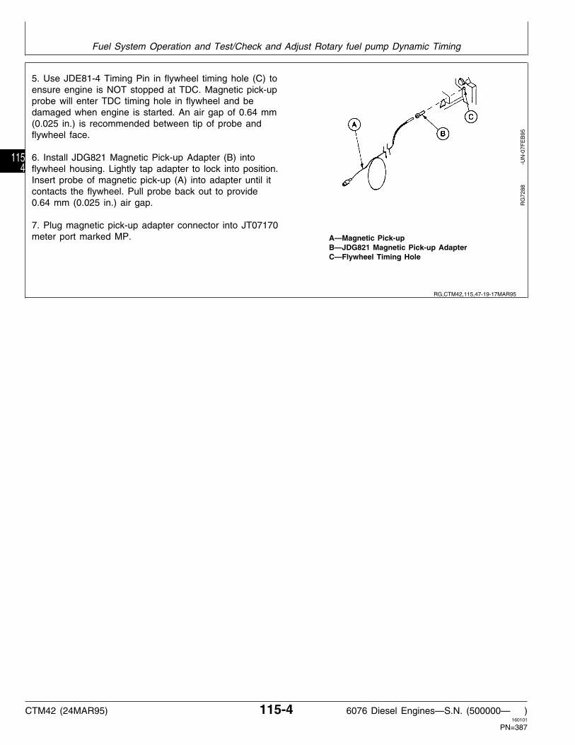
5. Use JDE81-4 Timing Pin in flywheel timing hole (C) toensure engine is NOT stopped at TDC. Magnetic pick-upprobe will enter TDC timing hole in flywheel and bedamaged when engine is started. An air gap of 0.64 mm(0.025 in.) is recommended between tip of probe andflywheel face.
6. Install JDG821 Magnetic Pick-up Adapter (B) intoflywheel housing. Lightly tap adapter to lock into position.Insert probe of magnetic pick-up (A) into adapter until itcontacts the flywheel. Pull probe back out to provide0.64 mm (0.025 in.) air gap.
7. Plug magnetic pick-up adapter connector into JT07170meter port marked MP. A—Magnetic Pick-up
B—JDG821 Magnetic Pick-up AdapterC—Flywheel Timing Hole
RG
7288
-U
N-0
7FE
B95
RG,CTM42,115,47-19-17MAR95
Fuel System Operation and Test/Check and Adjust Rotary fuel pump Dynamic Timing
CTM42 (24MAR95) 115-4 6076 Diesel Engines—S.N. (500000— )160101
PN=387
1154

• Check Injection Pump Rated Load Dynamic Timing:
1. Engine OFF. Push ON/CLEAR button.
Display shows: R=0
2. Push MAG PROBE button.
Display shows: Trig Level: 30%
3. Change to 70% and push ENTER.
RG
7031
-U
N-2
7SE
P94
RG
7032
-U
N-2
7SE
P94
RG,CTM8,G115,23-19-02FEB95
Fuel System Operation and Test/Check and Adjust Rotary fuel pump Dynamic Timing
CTM42 (24MAR95) 115-5 6076 Diesel Engines—S.N. (500000— )160101
PN=388
1155

Display shows: Offset: 20.0˚
4. Change to offset 0˚ and push ENTER.
Display shows: Calibrate?
5. Start engine and push ENTER.
RG
7033
-U
N-2
7SE
P94
RG
7129
-U
N-0
6OC
T94
RG,CTM8,G115,24-19-02FEB95
Fuel System Operation and Test/Check and Adjust Rotary fuel pump Dynamic Timing
CTM42 (24MAR95) 115-6 6076 Diesel Engines—S.N. (500000— )160101
PN=389
1156

6. Run engine at 1300 rpm. Push ENTER.
Display shows: Calibrating then Engine RPM and timing.
NOTE: If display shows NO PROBE, the magneticpick-up probe has not been installed properly [airgap exceeds 0.64 mm (0.025 in.)] or there isdebris on the back of the flywheel. Check forproper air gap or to clean the back side of theflywheel, insert a soft wooden dowel into theengine timing pin hole with the engine running atlow idle speed to clean the debris from flywheel.
7. Warm engine to normal operating temperature, checkslow and fast idle rpm. See FUEL INJECTION PUMPSPECIFICATIONS earlier in this group. Adjust speeds asnecessary.
RG,CTM8,G115,25-19-02FEB95
Fuel System Operation and Test/Check and Adjust Rotary fuel pump Dynamic Timing
CTM42 (24MAR95) 115-7 6076 Diesel Engines—S.N. (500000— )160101
PN=390
1157

IMPORTANT: Many machines have hydraulic pumpsthat have adequate flow to load enginewell below rated load rpm. Someequipment may need to be driven inhigh gear or pull a load to bring enginespeed to rated load rpm.
8. Run engine at wide open throttle (WOT) and loadengine down gradually to rated speed rpm.
NOTE: A negative timing value indicates the clamp-onsensor signal is not adequate. Check sensor andlines for cleanliness and proper installation.
9. Record engine speed (rpm) and timing degrees.
IMPORTANT: Stop engine prior to making timingadjustments. Injection pump can seizeif adjustment is made with enginerunning.
10. Stop engine.
If dynamic timing reading is more than 8 degreesretarded with pump flange and front plate timing marksat original location as shipped from factory, this mayindicate the pump advance is not functioning. Check thefollowing:
• Change fuel filter(s)• Check transfer pump for positive fuel pressure toinjection pump• Check camshaft movement on injection pumps withrectangular timing window.• Check pump drive shaft-to-gear key or pin to ensurekey or pin has not sheared.• If none of the above checks are conclusive, removepump and have necessary repairs made at an authorizeddiesel repair station.
RG
7037
-U
N-2
7SE
P94
RG,CTM8,G115,26-19-02FEB95
Fuel System Operation and Test/Check and Adjust Rotary fuel pump Dynamic Timing
CTM42 (24MAR95) 115-8 6076 Diesel Engines—S.N. (500000— )160101
PN=391
1158

• Adjust Injection Pump Dynamic Timing:
1. Loosen injection pump mounting flange nuts andadjust pump timing.
To advance pump timing, rotate top of pump clockwiseview from rear (flywheel end) of engine. To retard timing,rotate top of pump counterclockwise. Pump flangemovement of 1.524 mm (0.060 in.) is equivalent to 2degrees of engine timing.
2. Tighten injection pump mounting flange nuts to 47N·m (35 lb-ft). Start engine and check injection pumpdynamic timing again. Adjust timing as needed.
3. Grind away original timing mark and stamp new timingmark onto injection pump flange so timing mark (A)aligns after all final adjustments have been made andsatisfactory engine performance is achieved.
RG
6465
-U
N-2
6OC
T92
RG,CTM42,115,48-19-14FEB95
Fuel System Operation and Test/Check and Adjust Rotary fuel pump Dynamic Timing
CTM42 (24MAR95) 115-9 6076 Diesel Engines—S.N. (500000— )160101
PN=392
1159

FUEL SYSTEM OPERATION—IN-LINE FUEL INJECTION PUMP
A—Fuel Filter E—Supply Pump I—Fuel Shut-off Solenoid L—Injection PressureB—Check Valve Assembly F—Injection Pressure Lines J—Supply Pump Outlet M—Supply Pump PressureC—Pump Plungers G—Nozzles K—Round Primary N—Fuel ReturnD—Fuel Galley H—Leak-Off Line Filter/Water Separator O—Gravity Pressure
The supply pump (E) draws fuel from the vented fueltank through the primary filter (K).
The supply pump pressurizes the fuel so that it flowsthrough the filter (A) to the injection pump galley (D).Supply pump output pressure will vary depending onload and application.
The galley is kept full by the supply pump. Injectionpump plungers (C) further pressurize the fuel.Injection pressure lines (F) route the fuel to thenozzles (G).
The high pressure fuel opens the nozzle valve andforces fuel out the small orifices in the nozzle tip.This atomizes the fuel as it enters the combustionchamber.
There are two sources of excess fuel incorporatedinto the system. The supply pump supplies more fuelto the pump than is required by the engine, and thenozzle requires excess fuel to lubricate the nozzlevalve. A leak-off line (H) returns this excess fuel tothe tank from both the pump and nozzles.
RG
6665
-U
N-1
3MA
R93
RG,CTM42,115,3 -19-07APR93
Fuel System Operation and Test/Fuel System Operation—In-Line Fuel Injection Pump
CTM42 (24MAR95) 115-10 6076 Diesel Engines—S.N. (500000— )160101
PN=393
11510

FUEL SYSTEM OPERATION—ROTARY FUEL INJECTION PUMP
A—Electric Fuel Supply D—Injection Pressure Lines G—Fuel Supply Pump I—Fuel Return (Leak-off) LinePump E—Fuel Injection Nozzles Pressure Pressure
B—Fuel Filter F—Fuel Inlet Line H—Fuel Injection PumpC—Fuel Injection Pump Pressure
The electric fuel supply pump (A) draws fuel from thetank and pressurizes it. This pressure permits the fuelto flow through the filter (B) and charge the transferpump of the injection pump (C).
With the fuel injection pump charged with fuel by thefuel supply pump, the injection pump plungerspressurize the fuel to approximately 50 000 kPa (500bar) (7255 psi). Injection pressure lines (D) are usedto route this high pressure fuel to the fuel injectionnozzles (E).
Fuel enters the injection nozzle at a pressure whicheasily overcomes the pressure required to open thenozzle valve. When the nozzle valve opens, fuel isforced out through the orifices in the nozzle tip andatomizes as it enters the combustion chamber.
Incorporated into the fuel system is a means ofreturning excess (or unused) fuel back to the fueltank. Excess fuel comes from two sources:
1. Fuel Injection Pump: A quantity of fuel greater thanthat required by the engine is supplies to the fuelinjection pump.
2. Fuel Injection Nozzles: A small amount of fuelseeps past the nozzle valve for lubrication purposes.
To get the excess fuel back to the tank, a return linefrom the injection pump is connected to the middle ofthe nozzle leak-off line. Fuel from both sources isthen returned to the tank by a return pipe connectedto the front end of the leak-off pipe.
RG
6454
-U
N-2
2OC
T92
RG,CTM42,115,33-19-28OCT92
Fuel System Operation and Test/Fuel System Operation—Rotary Fuel Injection Pump
CTM42 (24MAR95) 115-11 6076 Diesel Engines—S.N. (500000— )160101
PN=394
11511

DIAGNOSE FUEL SYSTEM MALFUNCTIONS
NOTE: The following diagnostics apply to either standardmechanical in-line or rotary fuel pumps, orelectronic governor type fuel pumps. See CTM11for additional electronic pump diagnostics.
Symptom Problem Solution
Fuel Not Reaching Injection Fuel filter restricted Replace fuel filter (See Group 35)Nozzles
Fuel line restricted Clean lines as required
Fuel too heavy at low temperatures Use correct grade of fuel (SeeGroup 02)
Air in system Correct problem and bleed fuelsystem (this group)
Fuel tank valve shut off Open fuel tank valve
Low supply pump pressure Check fuel lines for restrictions;check pump output pressure (thisgroup)
Engine Starts Hard or Won’t Start Fuel too heavy at low temperature Use correct grade of fuel (SeeGroup 02)
Injection nozzles faulty or sticking Repair or replace as required (SeeGroup 35)
Incorrect timing Adjust timing (this group)
Faulty injection pump Repair or replace
Water in fuel Drain water from fuel (or separatorif equipped). Install new filter (SeeGroup 35)
Fuel filter restricted Replace fuel filters (See Group 35)
Low supply pump pressure Check pump output pressure. (Seethis group)
Injection pump return fuel line or Clean lines as requiredfittings restricted
Low cetane fuel Use correct grade of fuel (SeeGroup 02)
Broken starting fuel control shaft Repair (See Group 35)spring
Continued on next page
Fuel System Operation and Test/Diagnose Fuel System Malfunctions
CTM42 (24MAR95) 115-12 6076 Diesel Engines—S.N. (500000— )160101
PN=395
11512

Symptom Problem Solution
Injection pump drive gear teeth Check timing gear backlash andworn or broken check for failed crankshaft vibration
damper.
Engine Starts and Stops Air in system Correct problem and bleed fuelsystem (See this group)
Fuel filter restricted Replace fuel filter (See Group 35)
Fuel lines restricted Clean lines as required
Water in fuel Drain water from fuel, (or separatorif equipped). Install new filter (SeeGroup 35)
Injection pump return fuel line or Clean lines as requiredfittings restricted
Erratic Engine Operations Fuel filter restricted Replace fuel filter (See Group 35)
Fuel too heavy at low temperatures Use correct grade of fuel (SeeGroup 02)
Injection nozzles faulty or sticking Repair (See Group 35)
Fuel lines restricted Clean as required
Incorrect timing Adjust timing (this group)
Governor faulty Repair (See Group 35)
Water in fuel Drain water from fuel (or separator,if equipped). Install new filter
Injection pump return fuel line or Clean lines as requiredfittings restricted
Low cetane fuel Use correct grade of fuel (SeeGroup 02)
Injection nozzle return lines Clean lines as requiredrestricted
Engine Emits Excessive Black Injection nozzles faulty or sticking Repair (See Group 35)Smoke
Injection pump timing incorrect Adjust timing (this group)
Low cetane fuel Use correct grade of fuel (SeeGroup 02)
Continued on next page
Fuel System Operation and Test/Diagnose Fuel System Malfunctions
CTM42 (24MAR95) 115-13 6076 Diesel Engines—S.N. (500000— )160101
PN=396
11513

Symptom Problem Solution
Over-fueling Repair and adjust (See Group 35)
Aneroid defective Repair and adjust (See Group 35)
Engine Emits Excessive Blue or Cranking speed too low Check batteries and electricalWhite Smoke system
Injection pump timing incorrect Adjust timing (this group)
Injection nozzles faulty or sticking Repair (See Group 35)
Excessive wear in liners and/or See Group 10piston rings stuck
Incorrect cetane fuel for ambient Use correct grade of fuel (Seetemperature Group 02)
Engine running too “cold” Check thermostat (See Group 25)
Engine Idles Poorly Injection nozzles faulty or sticking Repair (See Group 35)
Incorrect timing Adjust timing (this group)
Pump slow idle speed not correctly Adjust slow idle speed (this group)adjusted
Fuel lines restricted Clean as required
Water in fuel Drain water from filter, (or separatorif equipped). Install new filters (SeeGroup 35)
Injection pump return lines or Clean as requiredfittings restricted
Injection nozzle return lines clogged Clean as required
Low cetane fuel Use correct grade of fuel (SeeGroup 02)
Engine Does Not Develop Full Low cetane fuel Use correct grade of fuel (SeePower Group 02)
Incorrect timing Adjust timing (this Group)
Injection pump or governor faulty Repair (See Group 35)
Fuel filter clogged Replace fuel filter (See Group 35)
Continued on next page
Fuel System Operation and Test/Diagnose Fuel System Malfunctions
CTM42 (24MAR95) 115-14 6076 Diesel Engines—S.N. (500000— )160101
PN=397
11514

Symptom Problem Solution
Injection nozzles faulty or sticking Repair (See Group 35)
Injection pump return fuel line or Clean as requiredfittings restricted
Engine Does Not Develop Full Water in fuel (or gasoline in fuel) Drain water or replace with cleanPower fuel Install new filters (this Group)
Incorrect fast idle speed Adjust speed (this Group)
Manifold pressure pipe to aneroid Repair as requiredloose or broken
Fuel shut-off cable improperly Adjustadjusted
RG,CTM42,115,2 -19-28OCT92
Fuel System Operation and Test/Diagnose Fuel System Malfunctions
CTM42 (24MAR95) 115-15 6076 Diesel Engines—S.N. (500000— )160101
PN=398
11515

MECHANICAL FUEL SUPPLY PUMP OPERATION
A—Fuel Inlet B—Plunger C—Fuel Outlet D—Hand Primer
Nippondenso pump shown
The plunger-type Robert Bosch or Nippondenso fuelsupply pump is used on 6076 engines. It is mountedon the side of the injection pump housing and isdriven by the injection pump camshaft. Fuel entersthe supply pump at (A), is pressurized by the plunger(B), and discharged through outlet (C). The handprimer (D) provides manual pump operation forbleeding the fuel system.
RG
5926
-U
N-1
9AU
G91
RG,CTM42,115,4 -19-28OCT92
Fuel System Operation and Test/Mechanical Fuel Supply Pump Operation Operation
CTM42 (24MAR95) 115-16 6076 Diesel Engines—S.N. (500000— )160101
PN=399
11516

MECHANICAL FUEL SUPPLY PUMP OPERATION—CONTINUED
A—Camshaft E—Plunger Spring I—Suction Valve M—Intermediate StrokeB—Roller Tappet F—Suction Chamber J—Fuel Inlet PositionC—Pressure Spindle G—Pressure Valve K—Hand Primer Pump N—Suction and DischargeD—Plunger H—Pressure Chamber L—Fuel Outlet Stroke Position
As the pump camshaft (A) rotates toward the “highcam” intermediate stroke position (M), the rollertappet (B) and pressure spindle (C) cause theplunger (D) to move against and compress theplunger spring (E).
Plunger movement forces the fuel out of the suctionchamber (F), through the pressure valve (G), and intothe pressure chamber (H). The amount of fueldischarged from the suction chamber is equal to theamount of fuel delivered for each stroke of theplunger. Towards the end of the intermediate stroke,the spring-loaded pressure valve closes again.
As the camshaft rotates toward the “low cam” orsuction and discharge position (N), plunger springpressure causes the plunger, pressure spindle, androller tappet to follow the camshaft.
Movement of the plunger pushes the fuel from thepressure chamber, and delivers it to the fuel filtersand injection pump. At the same time, plunger suctionpressure is permitting fuel to enter the suctionchamber through the suction valve (I). With thesuction chamber charged with fuel, the pumping cyclebegins again.
Fuel is allowed to flow in around the pressure spindleto lubricate the spindle as it moves back and forth inhousing. To prevent the fuel from entering the pumpcrankcase, a rubber O-ring is positioned in thespindle bore of housing at the roller tappet end.
Unscrewing the knurled knob on the hand primerpump (K) and pulling upward causes the suctionvalve to open and fuel to flow into the suctionchamber. When the hand plunger is pusheddownward, the suction valve closes, and fuel isforced out of the pressure valve.
RG
5787
-U
N-0
6AU
G91
RG,CTM42,115,5 -19-28OCT92
Fuel System Operation and Test/Mechanical Fuel Supply Pump Operation Operation
CTM42 (24MAR95) 115-17 6076 Diesel Engines—S.N. (500000— )160101
PN=400
11517

DIAGNOSING MECHANICAL FUEL SUPPLY PUMP MALFUNCTIONS
IMPORTANT: Visually inspect the fuel inlet fittingand pump filter for possibleplugging before disassembling todetermine cause of malfunction.
Symptom Problem Solution
Low Supply Pump Output Restriction at fuel inlet fitting. Thoroughly clean fuel tank, lines,Pressure or Pump Not filters, and inlet fitting.Functioning Correctly
Hand primer not screwed down Advise customer to tighten handtight, allowing dirt to enter hand primer after use.primer plunger chamber(Nippondenso pumps only).
Worn or pitted valves caused by Replace valves as required.foreign material lodging in valve.
Missing or broken spring(s). Replace spring(s).
Broken spindle. Replace pump.
Out of fuel. Add fuel to fuel tank.
Fuel shut off at tank. Open fuel shut off valve.
Restricted fuel line. Clean as required.
Air leak in fuel line between pump Repair as required.and tank.
Loose or damaged fuel line Repair.connetions.
Hand primer left in upward position Bleed fuel system, gently push hand(Nippondenso pump only) primer down and tighten securely.
Worn or damaged valve Repair or replace.assemblies/
Broken valve spring(s) Repair or replace.
RG,CTM42,G35,48-19-28OCT92
Fuel System Operation and Test/Diagnosing Mechanical Fuel Supply Pump Malfunctions
CTM42 (24MAR95) 115-18 6076 Diesel Engines—S.N. (500000— )160101
PN=401
11518

DIAGNOSE MECHANICAL FUEL SUPPLY PUMP MALFUNCTION—CONTINUED
Symptom Problem Solution
Diesel Fuel Leaking Into Injection Worn spindle and/or pump housing. Replace pump.Pump Crankcase
Defective O-ring seal. Replace O-ring seal.
Supply Pump Will Not Pump on Supply pump from A-Series Install correct supply pump onP-Size Pump Injection pump may have been injection pump.
installed.
Supply Pump Mounting Flange Supply pump from P-Series Install correct supply pump onBreaks When Mounted on A-Size Injection pump may have been injection pump.Pump and Operated installed.
TEST MECHANICAL FUEL SUPPLY PUMPFOR LEAKS
Fuel delivery pressure should be checked beforeremoving supply pump from injection pump. (SeeCHECK MECHANICAL FUEL SUPPLY PUMPOPERATION, in Group 115.)
1. Connect compressed air line (A) to a pressure gauge(B) and to supply pump inlet fitting. Air line should havea regulating valve to control pressure.
2. Cap or plug supply pump outlet fitting (C).
3. Submerge supply pump in a container of clean dieselfuel. Regulate air pressure to 200 kPa (2.0 bar) (29 psi).
4. Move roller tappet (Nippondenso pumps) or spindle(Bosch pumps) in and out by hand. No air bubblesshould appear around roller tappet or spindle bore.
NOTE: If bubbles appear, it is an indication that eitherthe O-ring seal is defective or spindle or tappet isworn (or possibly both).
IMPORTANT: Serious injection pump or enginedamage could occur, if enough dieselfuel leaks past spindle and seal. Fuelleakage past spindle dilutes engine oil.
RG
5894
-U
N-1
9AU
G91
RG,CTM42,115,21-19-28OCT92
RG,CTM42,G35,9 -19-28OCT92
Fuel System Operation and Test/Test Mechanical Fuel Supply Pump for Leaks
CTM42 (24MAR95) 115-19 6076 Diesel Engines—S.N. (500000— )160101
PN=402
11519

CHECK MECHANCIAL FUEL SUPPLY PUMPOPERATION
NOTE: The following test procedures can best beperformed under moderate air temperatureconditions to reduce electrical loads whencranking the engine is required.
• Test fuel supply pump and hand primer for leaks:
1. Make a preliminary inspection of supply pump.Thoroughly clean area around pump. All connectionsmust be tight and not leaking.
2. Start engine and bring to operating temperature.Shut-off engine.
NOTE: If fuel leaks around a Nippondenso hand primerthat is screwed down tight when engine isrunning, replace the hand primer.
Robert Bosch hand primers (A) are spring loadedto remain in the fully extended position. If fuelleaks around a Bosch hand primer while seatedin the extended position, replace the hand primer.
3. Check operation of hand primer. With engine shut-off,unscrew knob (Nippondenso only) and operate handprimer through several strokes. Moderate to heavyleakage of fuel between plunger and barrel indicates sealis defective. Replace hand primer.
NOTE: Appearance of a slight quantity of fuel around theplunger is normal.
IMPORTANT: On Nippondenso pumps, be sure handprimer is seated all the way down inbarrel before tightening to preventinternal thread damage.
4. On Nippondenso pumps only, tighten hand primerknob, but do not overtighten. If knob will not tighten(indicating internal thread damage), replace hand primer.
RG
5903
-U
N-1
9AU
G91
RG,CTM42,115,6 -19-17MAR95
Fuel System Operation and Test/Check Mechanical Fuel Supply Pump Operation
CTM42 (24MAR95) 115-20 6076 Diesel Engines—S.N. (500000— )160101
PN=403
11520

• Test operation of suction side of pump:
1. Disconnect suction and discharge lines at pump.
2. Drain all fuel from pump by operating hand primer.Then reconnect suction line to pump.
3. Operate hand primer until fuel flows from pumpoutlet (discharge). Fuel should flow within 15—25strokes. If not, the suction line may be obstructed orleaking air; (replace in-line filter when used).
NOTE: When operating hand primer, a moderateresistance should be felt. When only a slightresistance (or no resistance) occurs, replacehand primer or repair pump (valves may bedefective).
If fuel does not flow, and if no leak or obstruction isfound, pump is defective. Repair or replace pump.(See Group 35.)
• Test operation of discharge side of pump:
1. Suction line must be connected and discharge(pressure) line disconnected.
2. Tighten hand primer (Nippondenso only) and placeinjection pump fuel shut-off control in “STOP” positionto prevent engine from starting.
3. Crank engine with starting motor. Fuel should flowfrom pump outlet within 10 seconds. If not, thesuction line may be obstructed or leaking air; (replacein-line filter when used).
• Test pump output pressure while cranking engine:
1. Connect a 0—400 kPa (0—4 bar) (0—60 psi)pressure gauge to one end of a pressure hose about250—300 mm (10—12 in.) long. Connect other end ofhose to pump outlet. All air must be out of system.
IMPORTANT: The starting motor must crank theengine at normal cranking speed. Usebooster batteries if necessary.
2. Crank engine for 10 seconds with starting motor(approximately 300 engine rpm). Supply pump minimumoutlet pressure should be 200 kPa (2.0 bar) (29.0 psi).
3. Compare measured output with the minimum pressurespecifications.
If pressure is below the minimum specified and if noobstruction or leak is found, repair or replace the pump. R
G59
27
-
UN
-19A
UG
91
S11,23010,FJ -19-14FEB95
RG,CTM42,115,7 -19-17MAR95
Fuel System Operation and Test/Check Mechanical Fuel Supply Pump Operation
CTM42 (24MAR95) 115-21 6076 Diesel Engines—S.N. (500000— )160101
PN=404
11521

SERVICE MECHANICAL FUEL SUPPLYPUMP
NOTE: Gaining access to the valves on Robert Boschsupply pump requires removal and disassemblyof the supply pump, (See Group 35).
1. To gain access to the valves on Nippondenso supplypump, remove hand primer, banjo fitting, and plug fromtop of supply pump (shown removed).
2. Remove valves (B) and springs (A).
3. Inspect valves and valve seats for foreign material,wear or pitting. Valve springs must not be cracked orbroken. Nippondenso pump
4. Reassemble parts, open tank shut-off valve, andcheck operation. If the pump operation is still not normal,the pump will have to be repaired or replaced. (SeeGroup 35.)
RG
7815
3D1
-U
N-1
4DE
C88
RG,CTM42,115,8 -19-28OCT92
Fuel System Operation and Test/Service Mechanical Fuel Supply Pump
CTM42 (24MAR95) 115-22 6076 Diesel Engines—S.N. (500000— )160101
PN=405
11522

ELECTRIC FUEL SUPPLY PUMP OPERATION
A—Fuel Inlet B—Fuel Outlet
The electric supply pump is used on 6076 Enginesequipped with the rotary fuel injection pump.
As the coil is energized, the plunger is forced down.When the coil de-energizes, a spring forces theplunger back up creating a vacuum. The vacuumdraws fuel in through the inlet valve and fills theplunger area. This fuel is then forced out the top ofthe pump on the subsequent stroke. Maximumpressure delivered by this pump is 69 kPa (0.7 bar)(10 psi) at 2.8 A.
Operation of the pump can be determined by listeningfor a “clicking” sound when the key is “ON”. A sharpclicking is an indication that there is no fuel getting tothe pump. Fuel flowing through the pump muffles theclicking sound. If no clicking sound is heard, checkwiring harness for 12 v. If pumps clicks once thenquits, there is most likely an electrical problem in thepump and the pump will have to be replaced, as it isnot repairable.
RG
6450
-U
N-1
5OC
T92
RG,CTM42,115,24-19-28OCT92
Fuel System Operation and Test/Electric Fuel Supply Pump Operation
CTM42 (24MAR95) 115-23 6076 Diesel Engines—S.N. (500000— )160101
PN=406
11523

DIAGNOSE ELECTRIC FUEL SUPPLY PUMP MALFUNCTION
Symptom Problem Solution
Low Supply Pump Pressure or Out of fuel Add fuel to fuel tank.Pump Not Functioning Correctly
Fuel shut off at tank Open fuel shut-off valve.
Restricted fuel line Clean as required.
Air leak in fuel line between pump Repair as required.and tank
Loose or damaged fuel line Repair.connections
RG,CTM42,115,25-19-28OCT92
Fuel System Operation and Test/Diagnose Electric Fuel Supply Pump Malfunction
CTM42 (24MAR95) 115-24 6076 Diesel Engines—S.N. (500000— )160101
PN=407
11524
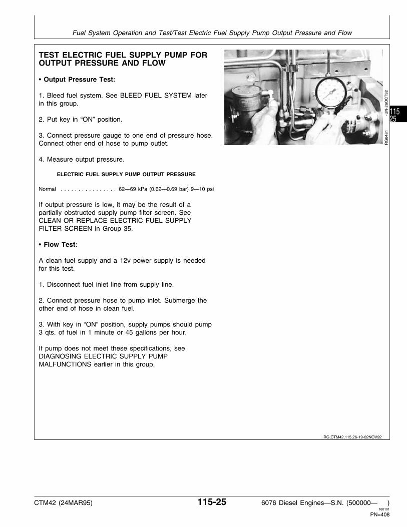
TEST ELECTRIC FUEL SUPPLY PUMP FOROUTPUT PRESSURE AND FLOW
• Output Pressure Test:
1. Bleed fuel system. See BLEED FUEL SYSTEM laterin this group.
2. Put key in “ON” position.
3. Connect pressure gauge to one end of pressure hose.Connect other end of hose to pump outlet.
4. Measure output pressure.
ELECTRIC FUEL SUPPLY PUMP OUTPUT PRESSURE
Normal . . . . . . . . . . . . . . . . 62—69 kPa (0.62—0.69 bar) 9—10 psi
If output pressure is low, it may be the result of apartially obstructed supply pump filter screen. SeeCLEAN OR REPLACE ELECTRIC FUEL SUPPLYFILTER SCREEN in Group 35.
• Flow Test:
A clean fuel supply and a 12v power supply is neededfor this test.
1. Disconnect fuel inlet line from supply line.
2. Connect pressure hose to pump inlet. Submerge theother end of hose in clean fuel.
3. With key in “ON” position, supply pumps should pump3 qts. of fuel in 1 minute or 45 gallons per hour.
If pump does not meet these specifications, seeDIAGNOSING ELECTRIC SUPPLY PUMPMALFUNCTIONS earlier in this group.
RG
6481
-U
N-2
6OC
T92
RG,CTM42,115,26-19-02NOV92
Fuel System Operation and Test/Test Electric Fuel Supply Pump Output Pressure and Flow
CTM42 (24MAR95) 115-25 6076 Diesel Engines—S.N. (500000— )160101
PN=408
11525

FUEL SHUT-OFF SOLENOID OPERATIONALCHECK
1. Observe fuel shut-off lever (A) when key switch isturned from “OFF” to “START” (engine running at slowidle) and then released to “ON” position.
2. Fuel shut-off lever should move from “NO FUEL”position (B) to “RUN” position (C) when starting motorbegins to crank. The lever should remain at the “RUN”position after key switch is released to “ON” position.
If fuel shut-off lever returns to “NO FUEL” position withkey switch at “ON” position, check for:
—Loss of battery voltage to fuel shutoff winding. Check voltage and wiring connection to solenoid.
—Binding of fuel shut-off lever, solenoid rod or linkage does not allow solenoid to lock in position. Repair or replace linkage.
—Torn or leaking rubber boot allowing dirt or moisture to enter at spring end of solenoid rod.
—Improperly adjusted fuel shut-off solenoid linkage. See FUEL SHUT-OFF SOLENOID LINKAGE ADJUSTMENT, later in this group.
3. Start engine and run at slow idle. Turn key switch to“OFF” position.
4. Fuel shut-off lever should move to “NO FUEL” positionand engine should stop.
If the solenoid stops just short of the “NO FUEL”position, slight adjustment of the linkage is required. SeeFUEL SHUT-OFF SOLENOID LINKAGE ADJUSTMENT,later in this group.
If engine continues to run with key switch at “OFF”position, unplug shut-off solenoid 3-way connector.
—If solenoid moves lever to “NO FUEL” position, problem is in the electrical circuit.
—If solenoid does not shut off fuel to engine, check linkage for binding or excessive tightness. Replacement service kit is available with a swivel rod which is less sensitive to misalignment and binding.
RW
1961
2
-U
N-0
4DE
C91
RW
1961
3
-U
N-0
4DE
C91
RG,CTM61,115,29-19-13MAY93
Fuel System Operation and Test/Test Electric Fuel Supply Pump Output Pressure and Flow
CTM42 (24MAR95) 115-26 6076 Diesel Engines—S.N. (500000— )160101
PN=409
11526

FUEL SHUT-OFF SOLENOID RESISTANCETEST
1. Disconnect shut-off solenoid 3-way WEATHERPACK™ connector.
2. Measure “PULL” coil resistance between black leadwire “C” and white lead wire “B”.
3. Measure “HOLD” coil resistance between black leadwire “C” and red lead wire “A”.
Replace solenoid if resistance is not within specificationgiven below.
PULL AND HOLD COIL RESISTANCE SPECIFICATIONS
Solenoid Pull Coil Hold CoilPart Number Resistance Resistance
(Ohms) (Ohms)
12-Volt System:RE53507, RE55415 . . . . . . 0.187—0.281 10.04—12.27RE53559 . . . . . . . . . . . . . 0.140—0.210 6.63—8.11
24-Volt System:RE54747, RE55416 . . . . . . 0.735—0.899 37.22—45.49RE53560 . . . . . . . . . . . . . 0.560—0.684 24.35—29.76
WEATHER PACK is a trademark of Packard Electric.
FUEL SHUT-OFF SOLENOID LINKAGEADJUSTMENT
Shut-off solenoid linkage is factory adjusted and usuallywill not require additional field adjustment. ALWAYScheck linkage and lever for alignment and binding beforemaking adjustments.
1. Thoroughly lubricate all linkage and lever pivot points.
A—Link2. If necessary, adjust linkage (A) so that lever (B) B—Levercontacts stop (C) with key switch “OFF” and engine not C—Stop
D—Stoprunning.
3. Start engine and run at slow idle. Lever shouldcontact stop (D) or nearly contact when the lever isbeing pushed up.
RW
1961
4
-U
N-0
4DE
C91
RW
1961
5
-U
N-0
4DE
C91
RG,CTM42,115,45-19-16AUG94
RG,CTM61,115,30-19-13MAY93
Fuel System Operation and Test/Fuel Shut-Off Solenoid Resistance Test
CTM42 (24MAR95) 115-27 6076 Diesel Engines—S.N. (500000— )160101
PN=410
11527

RECTANGULAR FUEL FILTER OPERATION
Fuel enters the filter at (A) and flows through a firststage filtering media (E) and a second stage filteringmedia (D) before flowing through outlet (B) to theinjection pump. The filtering media is housed in themetal sediment bowl (G) and epoxied to the bowl as oneassembly.
Since water and other contaminants may settle to thebottom of the sediment bowl, a drain plug (F) is providedto permit their removal.
An air vent (C) enables air in the fuel system to beexpelled to the outside through the filters when bleedplug is removed.
A—InletB—OutletC—Air VentD—Second Stage Filtering MediaE—First Stage Filtering MediaF—Drain PlugG—Sediment Bowl
R26
812
-UN
-28A
PR
89
ROUND (FINAL) FUEL FILTER OPERATION
Fuel enters the filter at the inlet (A), then flows through aprimary filter (B) and a secondary filter (C) before exitingfilter through outlet (D) to the fuel injection pump. Thefilter elements are housed in a sediment bowl attachedto the base with a threaded (detent) ring.
Since water and contaminants settle at the bottom of thesediment bowl, a drain plug (E) is provided.
Air in the system can be expelled through the air ventwhen bleed screw is loosened.
A—Fuel InletB—Primary FilterC—Secondary FilterD—Fuel OutletE—Drain Plug
RG
6444
-U
N-1
3OC
T92
RG,CTM42,115,27-19-28OCT92
RG,CTM42,115,28-19-28OCT92
Fuel System Operation and Test/Round (Final) Fuel Filter Operation
CTM42 (24MAR95) 115-28 6076 Diesel Engines—S.N. (500000— )160101
PN=411
11528

BLEED THE FUEL SYSTEM
N CAUTION: Escaping fluid under pressure canpenetrate the skin causing serious injury.Relieve pressure before disconnecting fuel orother lines. Tighten all connections beforeapplying pressure. Keep hands and body awayfrom pinholes and nozzles which eject fluidsunder high pressure. Use a piece of cardboardor paper to search for leaks. Do not use yourhand.
If ANY fluid is injected into the skin, it must besurgically removed within a few hours by adoctor familiar with this type injury organgrene may result. Doctors unfamiliar withthis type of injury may call the Deere &Company Medical Department in Moline,Illinois, or other knowledgeable medicalsource.
Whenever the fuel system has been opened up forservice (lines disconnected or filters removed), it will benecessary to bleed air from the system.
The fuel system may be bled at one of several locations.On some engine applications it may be necessary toconsult your operator’s manual and choose the locationbest for your engine/machine application.
X98
11
-UN
-23A
UG
88
A. At Rectangular Fuel Filter:
1. Loosen bleed plug (A) on fuel filter base.
NOTE: When bleeding the fuel system on enginesequipped with electronic governors, the keyswitch must be at the ’ON’ position so the fuelshutoff valve will be open to allow fuel flow.
RG
5870
-U
N-1
9AU
G91
S11,0408,AC -19-18APR94
RG,CTM42,G35,6 -19-02OCT92
Fuel System Operation and Test/Bleed the Fuel System
CTM42 (24MAR95) 115-29 6076 Diesel Engines—S.N. (500000— )160101
PN=412
11529

2. Unscrew hand primer on fuel supply pump until it canbe pulled by hand (Nippondenso pumps only).
NOTE: Robert Bosch supply pumps use a hand primerthat is spring loaded and remains fully extendedduring normal engine operation.
3. Operate the hand primer (A) on fuel supply pump untila smooth flow of fuel, free of bubbles, comes out of thefilter plug hole.
IMPORTANT: On Nippondenso pumps, be sure handBosch Pump Shownprimer is all the way down in barrel
before tightening to prevent internalthread damage.
4. Simultaneously stroke the hand primer down andclose the filter port plug. This prevents air from enteringthe system. Tighten plug securely. DO NOT overtighten.
5. Lock hand primer in position (Nippondenso pumpsonly).
NOTE: If the engine will not start, it may be necessary toloosen the fuel pipes at the injection nozzles tobleed air from system. Put the hand throttle inslow idle position. Push the engine fuel shut-offcontrol knob all the way in. Turn the engine withthe starter until fuel without air flows from theloose fuel pipe connections. Tighten theconnections.
RG
5903
-U
N-1
9AU
G91
B. At Round Fuel Filter:
NOTE: This procedure is for engine applications withelectric fuel supply pumps.
1. Open air bleed vent screw two full turns by hand.
2. Turn key switch “ON” until a noticeable amount of fueland air comes out of vent opening. Close vent screwwhen fuel starts to flow.
RG
6482
-U
N-2
6OC
T92
RG,CTM42,115,9 -19-28OCT92
RG,CTM42,G35,93-19-02NOV92
Fuel System Operation and Test/Bleed the Fuel System
CTM42 (24MAR95) 115-30 6076 Diesel Engines—S.N. (500000— )160101
PN=413
11530

C. At Fuel Injection Pump:
NOTE: This procedure is for engine applications withelectric fuel supply pumps.
1. Loosen fuel return line at fuel injection pump.
2. Turn key switch “ON”. As soon as fuel flow is freefrom air bubbles, tighten fuel return line.
RG
6483
-U
N-2
6OC
T92
D. At Fuel Injection Nozzles:
1. Place throttle lever in fast idle position.
2. Using two open-end wrenches, loosen fuel lineconnection at No. 1 injection nozzle.
3. Crank engine with starting motor (but do not startengine), until fuel free from bubbles flows out ofloosened connection. Retighten connection.
4. Repeat procedure for remaining injection nozzles (ifnecessary) until all air has been removed from fuelsystem. R
G64
84
-
UN
-26O
CT
92
RG,CTM42,G35,94-19-02NOV92
RG,CTM42,G35,95-19-28OCT92
Fuel System Operation and Test/Bleed the Fuel System
CTM42 (24MAR95) 115-31 6076 Diesel Engines—S.N. (500000— )160101
PN=414
11531

DIAGNOSE IN-LINE FUEL INJECTION PUMP MALFUNCTIONS
Symptom Problem Solution
Engine Starts Hard or Won’t Start Incorrect fuel shut-off lever position Adjust shut-off cable as required.(pump control rack not moving allthe way forward)
Defective injection pump Remove pump from engine andrepair (see Group 35)
Injection pump not correctly timed Check pump timing
Slow Idle Speed Irregular Slow idle stop screw improperly Recheck stop screw adjustmentadjusted
Supplementary idling spring Recheck adjustmentimproperly adjusted
Defective injection pump Remove pump from engine andrepair (See Group 35)
Engine Horsepower Low Pump not properly timed Check timing
Defective injection pump Remove pump from engine andrepair (See Group 35)
RG,CTM42,115,51-19-17MAR95
Fuel System Operation and Test/Diagnose In-Line Fuel Injection Pump Malfunctions
CTM42 (24MAR95) 115-32 6076 Diesel Engines—S.N. (500000— )160101
PN=415
11532

IN-LINE FUEL INJECTION PUMPOPERATION
Filtered fuel under pressure by the supply pump fills theinjection pump fuel gallery (G). As the camshaft rotates,roller tappets (C) riding on the camshaft (B) lobesoperate the plungers (F) to supply high pressure fuelthrough the delivery valves (H) to the injection nozzles.
A governor-operated control rack (D) is connected to thecontrol sleeves (E) and plungers to regulate the quantityof fuel delivered to the engine.
Engine lubricating oil is piped to the injection pumpcrankcase (A) to provide splash lubrication of theworking parts. Two drain holes at the front end of thepump determine the level of oil maintained in thecrankcase. Excess oil drains out these holes and returnsback to the engine through the timing gear housing.
A—CrankcaseB—CamshaftC—Roller TappetD—Control RackE—Control SleeveF—PlungerG—Fuel GalleryH—Delivery ValveI—Delivery PipeJ—Injection PressureK—Supply Pump PressureL—Engine Lubricating Oil
RG
4650
-U
N-1
4DE
C88
S11,23010,GF1 -19-14FEB95
Fuel System Operation and Test/In-Line Fuel Injection Pump Operation
CTM42 (24MAR95) 115-33 6076 Diesel Engines—S.N. (500000— )160101
PN=416
11533

CHECK FAST IDLE SPEED—IN-LINE FUELINJECTION PUMP
1. Remove speed control rod. With the engine running,move governor control lever (A) against the fast idle stopscrew (B).
NOTE: The governor control lever on injection pump maybe inboard (next to engine block) or outboard(away from engine block), depending uponengine application.
2. Using a tachometer, check fast idle speed to see if itis within specification.
NOTE: For each application, refer to the appropriatemachine technical manual for fast idle speedspecifications.
If fast idle speed must be adjusted, see your authorizeddiesel repair station.
NOTE: For some applications such as generator sets,special equipment may be required for fast idleadjustment in conjunction with droop adjustment.See your OEM dealer or John Deere EngineDistributor.
RG
3600
-U
N-1
4DE
C88
RG,CTM42,115,14-19-28OCT92
Fuel System Operation and Test/Check Fast Idle Speed—In-Line Fuel Injection Pump
CTM42 (24MAR95) 115-34 6076 Diesel Engines—S.N. (500000— )160101
PN=417
11534

CHECK AND ADJUST SLOW IDLESPEED—IN-LINE FUEL INJECTION PUMP
NOTE: Both the slow idle stop screw (A) and thebumper spring screw (B) may be used to adjustthe slow idle speed.
IMPORTANT: Minor adjustment of the slow idlespeed may be made with the bumperspring screw. However, it should not beused by itself to change engine speedmore than 50 rpm, as overspeeding of
(Robert Bosch)the engine may result.
If slow idle stop screw and bumperspring screw are not adjustedaccording to instruction, enginedamage could result because ofoverspeeding.
N CAUTION: ALWAYS STOP ENGINE beforemaking adjustments.
1. With the engine running, pull the governor controllever rearward to the slow idle speed position. Checkand adjust slow idle speed to specification. (Nippondenso)
NOTE: For each application, refer to the appropriatemachine technical manual for slow idle speed
A—Slow Idle Stop Screwspecifications. B—Bumper Spring Screw
C—Lock NutD—Lock Nut
RG
5942
-U
N-2
3AU
G91
RG
5943
-U
N-2
3AU
G91
RG,CTM42,115,34-19-16AUG94
Fuel System Operation and Test/Check and Adjust Engine Slow Idle Speed—In-Line Fuel Injection Pump
CTM42 (24MAR95) 115-35 6076 Diesel Engines—S.N. (500000— )160101
PN=418
11535

NOTE: On Nippondenso first remove slow idle stopscrew cover.
2. Loosen lock nut (C) and back out the bumper springadjusting screw (B) three turns.
3. Loosen lock nut (D) and adjust slow idle stop screw(A) to obtain an idle speed 50 rpm less that the desiredslow idle speed setting.
4. Turn the bumper spring adjusting screw in to increaseengine speed a maximum of 50 rpm to desired slow idle
Robert Bosch (Nippondenso similar)speed.
For example, to obtain an 850 rpm slow idle speed, useA—Slow Idle Stop Screwthe slow idle stop screw to set speed at approximatelyB—Bumper Spring Adjusting Screw800 rpm. Then increase speed to 850 rpm using theC—Lock Nutbumper spring adjusting screw.D—Lock Nut
NOTE: Increasing the slow idle speed a slight amountabove the specified speed range may help toreduce engine surge (or hunting). If this occurs,use the procedure given above; but do notexceed 850 rpm.
RG
5943
-U
N-2
3AU
G91
5. If engine surging or hunting persists at slow idle, thebumper spring (A) and adjustment screw (B) may needto be replaced with a new one. Remove the pump fromthe engine and have it repaired by an authorized dieselrepair station (ADS shop). See Group 35 for fuelinjection pump removal and installation.
6. Again check the fast and slow idle speeds. Readjust,slow idle speed if not correct.
7. Check all adjusting screw lock nuts for tightness.Install covers (and copper washers) on slow idle stopscrew and idling spring adjusting screw (on NippondensoPumps).
8. Connect fuel shut-off cable and speed control rod.
R28
387N
-UN
-14D
EC
88
RG,CTM42,115,35-19-16AUG94
RG,CTM42,115,36-19-16AUG94
Fuel System Operation and Test/Check and Adjust Engine Slow Idle Speed—In-Line Fuel Injection Pump
CTM42 (24MAR95) 115-36 6076 Diesel Engines—S.N. (500000— )160101
PN=419
11536
Fuel System Operation and Test/Check and Adjust Engine Slow Idle Speed—In-Line Fuel Injection Pump
CTM42 (24MAR95) 115-37 6076 Diesel Engines—S.N. (500000— )160101
PN=420
11537

ROTARY FUEL INJECTION PUMP OPERATION—STANADYNE DB4
1—Drive Shaft 6—Pressure Regulator 11—Governor 16—Rollers2—Distributor Rotor 7—Discharge Fitting 12—Governor Weights 17—Supply Pump Inlet3—Hydraulic Head 8—Metering Valve 13—Advance 18—Charging Ports4—Delivery Valve 9—Pumping Plungers 14—Drive Shaft Bushing 19—Throttle Lever5—Supply Pump 10—Internal Cam Ring 15—Housing
The main rotating components are the drive shaft (1),distributor rotor (2), supply pump (5), and thegovernor (11).
The drive shaft engages the distributor rotor inhydraulic head (3). The drive end of rotorincorporates two pumping plungers (9).
The plungers are actuated toward each othersimultaneously by an internal cam ring (10) throughrollers (16) and shoes which are carried in slots atdrive end of the rotor. The number of cam lobesnormally equal the number of engine cylinders.
The supply pump at rear of rotor is a positivedisplacement vane-type pump enclosed in the endcap. The end cap also houses supply pump inlet(17), fuel strainer and pressure regulator (6). Supplypump pressure is automatically compensated forviscosity effects due to temperature changes and fuelgrade variations.
The distributor rotor incorporates two charging ports(18) and a single axial bore (passage) with onedischarge port to serve all head outlets (7) to theinjection lines. The rotor rotates in bore of hydraulichead. Metering valve (8) bore, charging ports anddischarge fittings are located in the head.
RG
4910
-U
N-1
4DE
C88
RG,CTM42,115,29-19-28OCT92
Fuel System Operation and Test/Rotary Fuel Injection Pump Operation—Stanadyne DB4
CTM42 (24MAR95) 115-38 6076 Diesel Engines—S.N. (500000— )160101
PN=421
11538

(Refer to illustration on previous page).
This pump contains its own mechanical governor. Thecentrifugal force of the weights (12) in their retainer istransmitted through a sleeve to a governor arm andthrough a positive linkage to the metering valve. Themetering valve can be closed to shut off fuel througha solid linkage by an independently operated shut-offlever.
The automatic speed advance (13), advances orretards (hydraulically) the beginning of fuel deliveryfrom the pump. The advance responds to changes inspeed only, or to a combination of speed and loadchanges.
Fuel is drawn from the supply tank through filters intothe pump inlet through the inlet filter screen by thevane type fuel transfer pump. Some fuel is bypassedthrough the pressure regulator assembly to thesuction side.
Fuel under transfer pump pressure flows through thecenter of the transfer pump rotor, past the rotorretainer into a circular groove on the rotor. It thenflows through a connecting passage in the head tothe automatic advance and up through a radialpassage and then through a connecting passage tothe metering valve. The radial position of themetering valve, controlled by the governor, regulatesflow of the fuel into the radial charging passageswhich incorporates the head charging ports.
As the rotor revolves, the two rotor inlet passagesregister with the charging ports in the hydraulic head,allowing fuel to flow into the pumping chamber. Withfurther rotation, the inlet passages move out ofregistry and the discharge port of the rotor registerswith one of the head outlets. While the discharge portis opened, the rollers contact the cam lobes forcingthe plungers together. Fuel trapped between theplungers is then pressurized and delivered by thenozzle to the combustion chamber.
Self-lubrication is an inherent feature of the pump’sdesign. As fuel at transfer pump pressure reaches thecharging ports, slots on the rotor shank allow fuel andany entrapped air to flow into the pump housingcavity.
Additionally, an air vent passage in the hydraulichead connects the outlet side of the transfer pumpwith the pump housing. This allows air and some fuelto be bled back to the fuel tank via the return line.The fuel thus bypassed fills the housing, lubricatesthe internal components, cools and carries off anysmall air bubbles. The pump operates with thehousing completely full of fuel; there are no dead airspaces anywhere within the pump.
RG,CTM8,G115,3 -19-06FEB95
Fuel System Operation and Test/Rotary Fuel Injection Pump Operation—Stanadyne DB4
CTM42 (24MAR95) 115-39 6076 Diesel Engines—S.N. (500000— )160101
PN=422
11539

DIAGNOSE ROTARY FUEL INJECTION PUMP MALFUNCTIONS
Symptom Problem Solution
Engine Starts Hard or Shut-off solenoid not functioning Repair.Won’t Start properly; or wiring lead loose
or broken
Injection pump not correctly timed Check pump timing (refer to this group).
Defective injection pump Remove pump from engine and repair.
Automatic advance faulty or Adjust or repair.not operating
Slow Idle Speed Nozzle faulty or sticking Repair (See Group 35).Irregular
Automatic advance faulty Inspect and adjust or repair.or not operating
Injection pump not properly Check pump timing (refer to this group).timed
Defective injection pump Remove pump and repair.
Engine Horsepower Low Pump not properly timed Check timing (refer to this group).
Insufficient throttle arm travel Inspect and adjust.
Automatic advance faulty or Adjust or repair.not operating
Nozzle faulty or sticking Repair (See Group 35)
Defective injection pump Remove pump and repair.
RG,CTM42,115,30-19-28OCT92
Fuel System Operation and Test/Diagnose Rotary Fuel Injection Pump Malfunctions
CTM42 (24MAR95) 115-40 6076 Diesel Engines—S.N. (500000— )160101
PN=423
11540

CHECK AND ADJUST ENGINE SPEEDS ON ROTARY PUMP—STANADYNE DB4
A—Fast Idle Adjusting Screw B—Slow Idle Adjusting Screw
NOTE: Before adjusting engine speed, make sureengine has reached its normal operatingtemperature.
• Check Slow and Fast Idle Speeds:
1. Start engine and run at 50% load and rated speeduntil engine reaches normal operating temperature.
2. Stop engine and disconnect speed control rod orcable from injection pump throttle lever.
3. Start engine and run at slow idle and no-load untilengine stabilizes. Move injection pump throttle leverto slow idle position against adjusting screw stop.
4. Measure engine speed using a tachometer.Compare reading with specification.
Adjust slow idle speed if necessary as detailed below.
5. Move throttle lever to the fast idle position againstadjusting screw stop.
6. Read and record engine speed using atachometer. Compare readings with specifications.
IMPORTANT: If fast idle is not withinspecification, have an authorizeddiesel repair station, servicingdealer, or engine distributor adjustas necessary.
• Adjust Slow Idle Speed:
1. Hold pump throttle lever against slow idle stop.
2. Loosen slow idle adjusting screw lock nut. Turnadjusting screw clockwise to increase speed andcounterclockwise to decrease speed.
RG
6485
-U
N-2
6OC
T92
RG,CTM42,115,32-19-14FEB95
Fuel System Operation and Test/Check and Adjust Engine Speeds on Rotary Pump
CTM42 (24MAR95) 115-41 6076 Diesel Engines—S.N. (500000— )160101
PN=424
11541

HOW THE ANEROID WORKS (IFEQUIPPED)—IN-LINE INJECTION PUMPS
Intake manifold pressure (created by the turbocharger)enters aneroid at (A). It is directed to upper side ofdiaphragm chamber (C) and exerts pressure ondiaphragm (D).
When the pressure rises to about 100 kPa (1 bar) (15psi), or about 1000 engine rpm under moderate to heavyloads, spring pressure (E) is overcome. Diaphragm thenmoves adjusting shaft screw (F) downward.
Arm (G) has two “legs”. The inner leg bears on the flatsurface of adjusting shaft screw (F). The outer leg bearsagainst a block riveted to the control rack (H).
NOTE: Diaphragm adjusting screw (B) regulates theminimum fuel delivery quantity at a specified rpmand zero pressure acting on the diaphragm. Thediaphragm spring determines acceleration time(the greater the spring tension, the greater themanifold pressure required to overcome springtension; hence, a slower acceleration).
Downward movement of the adjusting shaft causes armto rotate on starting fuel control shaft (I), permitting
A—Intake Manifold Pressure Openingcontrol rack to move its normal amount. B—Adjusting Screw
C—Diaphragm ChamberIf the intake manifold pressure is below 100 kPa (1 bar) D—Diaphragm
E—Spring(15 psi) because of low engine speed, or is under lightF—Adjusting Shaft Screwload at higher engine speeds, the aneroid springG—Arm
pressure is greater than the intake manifold pressure. As H—Control Racka result, the control rack travel is limited (therefore, fuel I—Starting Fuel Shaftdelivery is limited) by the arm and adjusting shaft.
Aneroid control will be in effect until the manifoldpressure is high enough to overcome diaphragm springpressure.
A hydraulic aneroid activator (described in this group) isused to control the lever arm engagement with thecontrol rack by moving the starting fuel control shaft in orout.
During starting, the hydraulic aneroid activatordisengages the lever arm from the control rack block topermit the rack to move all the way forward to thestarting fuel delivery position.
R27
340N
-UN
-14D
EC
88
S11,23010,IU -19-14FEB95
Fuel System Operation and Test/How the Aneroid Works—In-Line Injection Pumps
CTM42 (24MAR95) 115-42 6076 Diesel Engines—S.N. (500000— )160101
PN=425
11542

DIAGNOSE ANEROID MALFUNCTION
Symptom Problem Solution
Slow Engine Acceleration Loose pipe or broken connection at Repair as required. (See Group 35)inlet fitting
Aneroid cover cracked around inlet Repair as required. (See Group 35)fitting
Defective diaphragm Repair as required. (See Group 35)
Aneroid not correctly adjusted Remove injection pump (See Group35) and adjust on test stand.
Excessive Smoke When Aneroid not correctly adjusted Remove injection pump. (See GroupAccelerating Engine 35) and adjust on test stand.
Use information contained in the chart above to helpdiagnose aneroid malfunctions.
See Group 35 for instructions on how to repair andadjust the aneroid.
The aneroid controls fuel delivery when intakemanifold pressure is about 100 kPa (1 bar) (15 psi)or less. Therefore, all final adjustments are to bemade on the test stand with aneroid mounted oninjection pump.
IMPORTANT: Correct aneroid adjustments areessential for satisfactory engineperformance. Whenever the aneroidhas been disassembled or theadjustments have been altered, theinjection pump (including aneroid)must be calibrated on the test standby an authorized diesel injectionrepair station before releasing thepump for service.
S11,23010,IV -19-17MAR92
S11,23010,IV1 -19-09SEP91
Fuel System Operation and Test/Diagnose Aneroid Malfunctions
CTM42 (24MAR95) 115-43 6076 Diesel Engines—S.N. (500000— )160101
PN=426
11543

HOW THE HYDRAULIC ANEROIDACTIVATOR WORKS (IF EQUIPPED)
The hydraulic aneroid activator mounts on the inboardside of the governor housing. It has an internal piston (F)that is operated by engine oil pressure to hydraulicallymove the starting fuel control shaft inward for aneroidcontrol.
Engine lubricating oil is piped from the oil filter body tooperate the activator. This oil is then piped to theinjection pump housing to lubricate the internal workingparts.
Engine oil upon starting the engine is routed to theaneroid activator housing (I) through a banjo connector(A), special screw (B), and an orifice in the capillary
A—Activator Banjo Connectorvalve (E) to head of piston (F). B—Special Screw
C—Capillary Valve SpringWhenever the engine oil pressure is about 60 kPa (0.6 D—Restrictor Wire
E—Capillary Valvebar) (9 psi) or higher, the piston will overcome resistanceF—Pistonof piston spring (G) and move the starting fuel controlG—Piston Spring
shaft (H) inward to provide aneroid control. H—Starting Fuel Control ShaftI—Activator Housing
Loss of oil pressure permits a return spring on thestarting fuel control shaft to hold the lever arm out ofengagement with the control rack. This prevents theaneroid from limiting rack travel.
A restrictor wire (D) is inserted in the capillary valve fortwo reasons.
(1) To retard engagement of the aneroid when engine iscold.
(2) To help maintain an open passage in the capillaryvalve (oil pressure action moves the wire enough toprevent orifice from plugging).
The length of time required to achieve aneroid controldepends on the ambient air temperature and theviscosity of the engine oil. Warm ambient airtemperatures will permit the aneroid to activate in a fewseconds. Cold temperatures may delay activation forseveral minutes.
R27
342N
-UN
-14D
EC
88
S11,23010,AB -19-28OCT92
Fuel System Operation and Test/How the Hydraulic Aneroid Activator Works
CTM42 (24MAR95) 115-44 6076 Diesel Engines—S.N. (500000— )160101
PN=427
11544

The following table gives the approximate ambienttemperature-engagement time based on different enginelubricating oil viscosities:
Engine EngagementAmbient Temp. Crankcase in Seconds
˚C (˚F) Oil (Approx.)
-1 (30) SAE 30 86-18 (1) 10W-20 255
-29 (-20) 5W-20 360
DIAGNOSE MALFUNCTIONS—HYDRAULIC ANEROID ACTIVATOR
Symptom Problem Solution
Engine Starts Hard Broken return spring on starting fuel Repair (See Group 35)control shaft.
Retaining ring missing from starting Repair (See Group 35)fuel control shaft.
Excessive Smoke When Check for restriction in oil supply Disassemble activator (See GroupAccelerating Engine passages to activator piston. 35)
S11,23010,AC -19-16AUG94
S11,23010,IW -19-28OCT92
Fuel System Operation and Test/Diagnose Malfunctions—Hydraulic Aneroid Activator
CTM42 (24MAR95) 115-45 6076 Diesel Engines—S.N. (500000— )160101
PN=428
11545
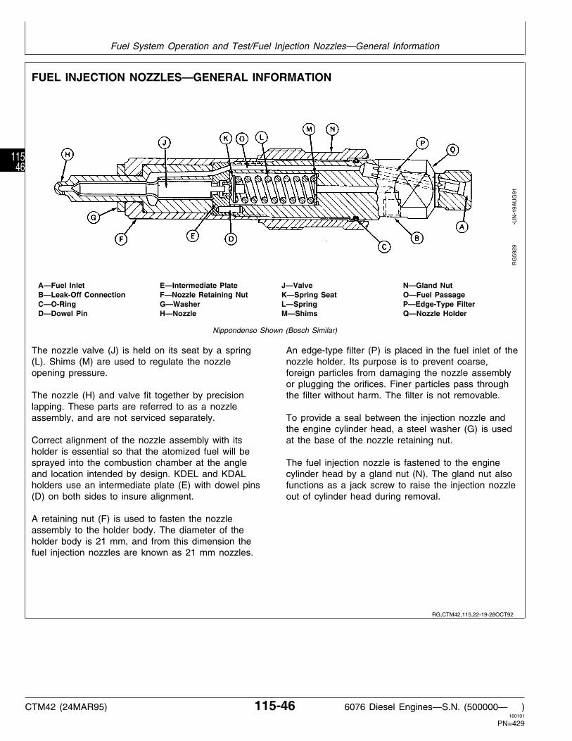
FUEL INJECTION NOZZLES—GENERAL INFORMATION
A—Fuel Inlet E—Intermediate Plate J—Valve N—Gland NutB—Leak-Off Connection F—Nozzle Retaining Nut K—Spring Seat O—Fuel PassageC—O-Ring G—Washer L—Spring P—Edge-Type FilterD—Dowel Pin H—Nozzle M—Shims Q—Nozzle Holder
Nippondenso Shown (Bosch Similar)
The nozzle valve (J) is held on its seat by a spring(L). Shims (M) are used to regulate the nozzleopening pressure.
The nozzle (H) and valve fit together by precisionlapping. These parts are referred to as a nozzleassembly, and are not serviced separately.
Correct alignment of the nozzle assembly with itsholder is essential so that the atomized fuel will besprayed into the combustion chamber at the angleand location intended by design. KDEL and KDALholders use an intermediate plate (E) with dowel pins(D) on both sides to insure alignment.
A retaining nut (F) is used to fasten the nozzleassembly to the holder body. The diameter of theholder body is 21 mm, and from this dimension thefuel injection nozzles are known as 21 mm nozzles.
An edge-type filter (P) is placed in the fuel inlet of thenozzle holder. Its purpose is to prevent coarse,foreign particles from damaging the nozzle assemblyor plugging the orifices. Finer particles pass throughthe filter without harm. The filter is not removable.
To provide a seal between the injection nozzle andthe engine cylinder head, a steel washer (G) is usedat the base of the nozzle retaining nut.
The fuel injection nozzle is fastened to the enginecylinder head by a gland nut (N). The gland nut alsofunctions as a jack screw to raise the injection nozzleout of cylinder head during removal.
RG
5929
-U
N-1
9AU
G91
RG,CTM42,115,22-19-28OCT92
Fuel System Operation and Test/Fuel Injection Nozzles—General Information
CTM42 (24MAR95) 115-46 6076 Diesel Engines—S.N. (500000— )160101
PN=429
11546

FUEL INJECTION NOZZLE OPERATION
Fuel lines (A) deliver the fuel to injection nozzles. Fuelenters the injection nozzle inlet (B), and passes throughthe edge-type filter (C). Coarse foreign particles areretained by the filter.
A passage (D) routes fuel through the nozzle holder tothe nozzle valve (E). The nozzle valve is lifted instantlyoff its seat by the high pressure inlet fuel acting on anannulus in the valve.
NOTE: Since the nozzle valve opening pressure isconsiderably lower than the injection pump outputpressure, the inlet fuel pressure easily overcomesthe resistance of the nozzle valve spring (G).
When the nozzle valve opens, a definite quantity of fuel(determined by the injection pump output for eachplunger stroke) is forced out through orifices (F). Thefuel becomes finely atomized as it is sprayed into thecombustion chamber at high velocity.
The nozzle assembly is lubricated by a small amount offuel which seeps between the lapped surfaces of thenozzle and valve which accumulates around the spring(G, refer to previous illustrations).
The leakage fuel is routed out the nozzle holder througha leak-off connector (H) and returned back to the fueltank by means of a leak-off pipe (I).
Fuel Flow Through KDEL Injection Nozzle
A—Fuel Delivery LineB—Fuel InletC—Edge-Type FilterD—Fuel PassageE—Nozzle ValveF—OrificesG—Nozzle Valve SpringH—Leak-Off ConnectorI—Leak-Off PipeJ—Engine Cylinder HeadK—High Pressure FuelL—Low Pressure (Return) Fuel
RG
4651
-U
N-2
9AU
G94
S55,23010,P -19-16SEP94
Fuel System Operation and Test/Fuel Injection Nozzle Operation
CTM42 (24MAR95) 115-47 6076 Diesel Engines—S.N. (500000— )160101
PN=430
11547

DIAGNOSE MALFUNCTIONS—FUEL INJECTION NOZZLE
Fuel injection nozzles are usually removed from theengine when there is a noticeable loss of power orexcessive smoking.
Listed in the following chart are various malfunctionswhich may occur on the 21 mm nozzles. Onlypossible defects related to these nozzles are listed.Failures in other components of the fuel injectionsystem are listed under their respective headings inthis group.
See Group 35 for repair information.
Symptom Problem Solution
Engine Has Low Horsepower Nozzle orifices plugged Repair (See Group 35)
Incorrect nozzle valve opening Adjust (See Group 35)pressure
Broken or damaged parts Repair as required (See Group 35)
a. Broken nozzle valve springb. Cracked or split nozzle tipc. Cracked or split nozzle bodyd. Internal leak
Wrong nozzle and valve in holder Install correct nozzle assembly (SeeGroup 35)
Nozzle loose in cylinder head Make sure R84472 Steel Washer isinstalled on tip end of injectionnozzle. Tighten to specified torque(See Group 35)
Engine Emits Too Much Smoke Nozzle orifices plugged Repair (See Group 35 Diesel FuelSystem)
Broken or damaged parts Repair as required (See Group 35)Diesel Fuel System
a. Broken nozzle valve springb. Cracked or split nozzle tipc. Cracked or split nozzle bodyd. Internal leak
Wrong nozzle and valve in holder Install nozzle assembly (See Group35 Diesel Fuel System)
Worn nozzle valve seal Replace nozzle assembly (SeeGroup 35 Diesel Fuel System)
RG,CTM42,115,23-19-28OCT92
Fuel System Operation and Test/Diagnose Malfunctions—Fuel Injection Nozzle
CTM42 (24MAR95) 115-48 6076 Diesel Engines—S.N. (500000— )160101
PN=431
11548

TEST FUEL INJECTION NOZZLES (ENGINE RUNNING)
1. Operate engine at intermediate speed and no load.
2. Slowly loosen the fuel pressure line at one of thenozzles until fuel escapes at the connection (fuel notopening nozzle valve).
NOTE: The injection nozzle before and/or after nozzlebeing checked could be the faulty nozzle.
• If engine speed changes, the injection nozzle isprobably working satisfactory.
• If engine speed does not change, a nozzle is faultyand must be checked and repaired (or replaced).
3. Repeat test for each remaining nozzle assembly.
4. Remove faulty injection nozzles and repair asrequired. See Group 35.
FUEL DRAIN BACK TEST PROCEDURE
Fuel draining back through the fuel system maycause hard starting. This procedure will determine ifair is entering the system at connections and allowingfuel to siphon back to the fuel tank.
1. Disconnect fuel supply line and fuel return line atfuel tank.
IMPORTANT: Fuel return line MUST extend belowfuel level in fuel tank beforeperforming this test. Fill fuel tank ifnecessary.
2. Drain all fuel from the system, including the fueltransfer pump, fuel injection pump, fuel filters, andwater separator (if equipped).
3. Securely plug off the end of the fuel return pipe.
4. Using a low pressure air source, pressurize thefuel system at the fuel supply line.
N CAUTION: Maximum air pressure should be100 kPa (1 bar) (15 psi) when performingthis test.
5. Apply liquid soap and water solution to all jointsand connections in the fuel system and inspect forleaks.
NOTE: Connections may allow air to enter the systemwithout allowing fuel to leak out.
6. If any leaks are found, take necessary steps torepair.
7. Reconnect supply and return lines and primesystem.
8. Start engine and run for approximately 10 minutes.
9. Allow engine to sit overnight and try starting thefollowing morning.
S11,23010,HR -19-18APR94
S11,23010,JA -19-28OCT92
Fuel System Operation and Test/Fuel Drain Back Test Procedure
CTM42 (24MAR95) 115-49 6076 Diesel Engines—S.N. (500000— )160101
PN=432
11549

INSTRUCTIONS FOR CHANGING 6076 GEN SET ENGINE RATED SPEED FROM 1800RPM (60 HZ) TO 1500 RPM (50 HZ)—MECHANICAL GOVERNOR
A—Droop Adjusting Screw D—Throttle Lever F—Idle (Bumper) Spring H—Fast Idle (Stop) ScrewB—Governor Housing E—Slow Idle (Adjusting) G—Mechanical Shutoff LeverC—Droop Adjusting Screw Screw
Access Plug
This instruction covers step-by-step adjustmentprocedures for changing 6076 Gen Set Engine ratedspeed from 1800 RPM (60 Hz) to 1500 RPM (50 Hz)while maintaining the desired speed regulation.
IMPORTANT: Only qualified technicians shouldattempt the adjustments covered inthis instruction. If qualifications arein doubt, have your nearest ADSrepair shop perform theseadjustments.
To assure specified power andgoverning during engine operation,the throttle lever must be fixedagainst the fast idle (stop) screw(H).
To assure specified governing, thefast idle screw and bumper springscrew (F) must be readjusted anytime the droop screw (A) isadjusted.
If an electric shutoff solenoid isconnected to the shutoff lever (G)by rigid linkage, it must be adjustedto provide a gap of 0.0762 mm(0.003 in.), (one paper thickness)between the lever and stop. Toomuch gap will limit rack travel, nogap will bind the lever shaft. Ifflexible linkage is used, it should beadjusted for no gap.
RG
5753
-U
N-0
5AU
G91
RG,GENSET4,1 -19-11FEB93
Fuel System Operation and Test/Fuel Drain Back Test Procedure
CTM42 (24MAR95) 115-50 6076 Diesel Engines—S.N. (500000— )160101
PN=433
11550

CHANGE ENGINE RATED SPEED FROM1800 RPM TO 1500 RPM AND ADJUSTDROOP
1. Start engine and apply 50% load at rated speed untilit reaches operating temperature. Remove cap nuts fromadjusting screws before making adjustments.
2. When the engine has reached normal operatingtemperature, adjust fast idle (stop) screw (A) clockwise(CW) to 1500 rpm (50 Hz) with 100 % (full) load.
3. Remove load and back out the idle (bumper) springscrew (E), while observing the corresponding drop inengine rpm’s until engine quits losing speed.
4. Screw in idle (bumper) spring screw until enginespeed increases 5—10 rpm.
5. Check for specified no-load (frequency). If governorregulation is within 5—7% range, proceed to Step 8.
NOTE: A noticable click will occur at each 1/4 turn ofdroop adjusting screw. One click CW willincrease no-load speed approximately 10 rpm,counter-clockwise (CCW) will reduce speed by 10rpm. Maximum 24 clicks out, minimum 4 clicksout with final setting.
A—Fast Idle (Stop) Screw6. If governor regulation is above 7% or below 5%, stop B—Droop Adjusting Screw Access Plug Locationengine and remove droop adjusting screw access plug C—Droop Adjusting Screw
D—Slow Idle (Adjusting) Screw(B, shown removed) from top of governor housing.E—Idle (Bumper) SpringF—Throttle Levera. Back out slow idle (adjusting) screw (D) and andG—Mechanical Shutoff Leverbumper screw. Pull back on throttle lever (F, toward
rear of governor housing) by hand until the droopadjusting screw (C) inside housing can be adjustedthrough the access plug hole.
b. Screw the droop screw in (CW), counting the turnsuntil screw bottoms out. Then, return screw tooriginal setting.
c. Screw in the droop screw (CW) no more than 1/2 turn(two clicks) at a time to reduce governor droop. CCWno more than two clicks at a time to increasegovernor droop (to reduce governor sensitivity).
d. Replace access plug in top of governor housing. Startengine, apply full (100%) load, and readjust highidle adjusting screw until 1500 rpm (50 Hz) isobtained at the specified power.
e. Screw in idle (bumper) spring until engine speedincreases 5—10 rpm.
7. Repeat Steps 6 (a—d) until governor regulation iswithin the 5—7% range.
Replace all cap nuts onto adjusting screws and tightenlock nuts securely.
RG
5752
-U
N-0
5AU
G91
RG,GENSET4,3 -19-11FEB93
Fuel System Operation and Test/Fuel Drain Back Test Procedure
CTM42 (24MAR95) 115-51 6076 Diesel Engines—S.N. (500000— )160101
PN=434
11551

Fuel System Operation and Test/Fuel Drain Back Test Procedure
CTM42 (24MAR95) 115-52 6076 Diesel Engines—S.N. (500000— )160101
PN=435
11552

HOW TO MAKE TOOLS
These tools can be made in a service shop usingcommon shop tools and locally obtained materials.
DFRG3—CYLINDER LINER HOLDING FIXTURE
1—254.0 mm (10 in.) 8—31.8 mm (1.25 in.) 15—2 used 20—111.25 mm (4.38 in.)2—127.0 mm (5 in.) 9—63.5 mm (2.5 in.) 16—304.8 mm (12 in.) 21—60.45 mm (2.38 in.)3—38.1 mm (1.5 in.) 10—25.4 mm (1 in.) 17—5/16 in—18 Tap 22—5/16 in. x 1 in. Cap4—405.4 mm (16 in.) 11—6.35 mm (0.25 in.) 18—69.85 mm (2.75 in.) Screw5—330.2 mm (13 in.) 12—152.4 mm (6 in.) Radius 23—38.1 mm (1.5 in.) Angle6—9.52 mm (0.38 in.) 13—0.328 in. Drill Through 19—101.6 mm (4 in.) Iron7—12.7 mm (0.5 in.) 14—5/16 in.—18 Tap
T36
748N
-UN
-24O
CT
88
S55,DFRG -19-01DEC89
S55,DFRG3 -19-23FEB87
Group 199Dealer Fabricated Tools
CTM42 (24MAR95) 199-1 6076 Diesel Engines—S.N. (500000— )160101
PN=436
1991

Dealer Fabricated Tools/Cylinder Liner Holding Fixture
CTM42 (24MAR95) 199-2 6076 Diesel Engines—S.N. (500000— )160101
PN=437
1992

Page
AAdditives
Coolant . . . . . . . . . . . . . . . . . . . . . . . . 02-10Aftercooler
Inspect . . . . . . . . . . . . . . . . . . . . . . . . 30-26Install horizontally-mounted . . . . . . . . . . . 30-29Install vertically-mounted . . . . . . . . . . . . 30-27Remove horizontally-mounted . . . . . . . . . 30-25Remove vertically-mounted . . . . . . . . . . . 30-23Repair . . . . . . . . . . . . . . . . . . . . . . . . . 30-26
Air cleanerOperation . . . . . . . . . . . . . . . . . . . . . . 110-4
Air intake coverInspect . . . . . . . . . . . . . . . . . . . . . . . . 30-26
Air intake manifold pressureAneroid . . . . . . . . . . . . . . . . . . . . . . . . 110-9Intake manifold . . . . . . . . . . . . . . . . . . 110-10
Air intake systemCheck . . . . . . . . . . . . . . . . . . . . . . . . . 100-7Diagnostics . . . . . . . . . . . . . . . . . . . . . 110-3General information . . . . . . . . . . . . . . . . 110-4Specifications . . . . . . . . . . . . . . . . . . . . . 30-2
Altitude compensation . . . . . . . . . . . . . . . . 100-1Aneroid
Diagnostics . . . . . . . . . . . . . . . . . . . . 115-43General information . . . . . . . . . . . . . . . 115-42Repair . . . . . . . . . . . . . . . . . . . . . . . . . 35-21
Aneroid, hydraulic activatorClean . . . . . . . . . . . . . . . . . . . . . . . . . 35-22Diagnostics . . . . . . . . . . . . . . . . . . . . 115-45Disassemble . . . . . . . . . . . . . . . . . . . . 35-22General information . . . . . . . . . . . . . . . 115-44Install . . . . . . . . . . . . . . . . . . . . . . . . . 35-22Remove . . . . . . . . . . . . . . . . . . . . . . . 35-21
Aneroid, hydrualic activatorAssemble . . . . . . . . . . . . . . . . . . . . . . 35-22
BBearing cap, main
Measure line bore . . . . . . . . . . . . . . . . . 15-33Bearings
Failure analysis . . . . . . . . . . . . . . . . . . . 15-8Measure assembled ID . . . . . . . . . . . . . 15-32
Bearings, connecting rodInspect and measure . . . . . . . . . . . . . . . 10-23
Bearings, flywheel, crankshaftFinal assembly . . . . . . . . . . . . . . . . . . . 15-52
Page
Bearings, mainCheck clearance . . . . . . . . . . . . . . . . . . 15-28Install . . . . . . . . . . . . . . . . . . . . . . . . . 15-41Remove . . . . . . . . . . . . . . . . . . . . . . . 15-27
Bearings, thrustSpecifications . . . . . . . . . . . . . . . . . . . . 15-36
Belt tensioner . . . . . . . . . . . . . . . . . . . . . 25-13Belt, fan
Tension specifications . . . . . . . . . . . . . . 25-26Block, cylinder
Clean and inspect top deck . . . . . . . . . . 05-29Disassemble . . . . . . . . . . . . . . . . . . . . 10-29Inspect and clean . . . . . . . . . . . . . . . . . 10-30Measure . . . . . . . . . . . . . . . . . . . . . . . 10-32
Break-In Engine Oil . . . . . . . . . . . . . . . . . . 02-2Break-in, engine
Guidelines . . . . . . . . . . . . . . . . . . . . . . 100-5Perform . . . . . . . . . . . . . . . . . . . 05-42, 100-6
Bushing, piston pinRemove . . . . . . . . . . . . . . . . . . . . . . . 10-27
Bushings, camshaftService (using JDG602) . . . . . . . . . . . . . 16-15Service (using JDG606) . . . . . . . . . . . . . 16-17
Bushings, piston pinInspect . . . . . . . . . . . . . . . . . . . . . . . . 10-26
Bypass valve, oil filterRemove, inspect, and install . . . . . . . . . . . 20-5
CCamshaft
Assemble . . . . . . . . . . . . . . . . . . . . . . 16-14End play . . . . . . . . . . . . . . . . . . . . . . . . 16-7Inspect . . . . . . . . . . . . . . . . . . . . . . . . 16-12Install . . . . . . . . . . . . . . . . . . . . . . . . . 16-18Measure drive gear backlash . . . . . . . . . . 16-8Remove . . . . . . . . . . . . . . . . . . . . . . . . 16-9Specifications . . . . . . . . . . . . . . . . . . . . . 16-4
Camshaft bushing IDMeasure . . . . . . . . . . . . . . . . . . . . . . . 16-13
Camshaft bushingsService (using JDG602) . . . . . . . . . . . . . 16-15Service (using JDG606) . . . . . . . . . . . . . 16-17
Camshaft followersInspect and measure . . . . . . . . . . . . . . . 16-12
Camshaft gearsInstall . . . . . . . . . . . . . . . . . . . . . . . . . 16-14Remove . . . . . . . . . . . . . . . . . . . . . . . 16-11
Camshaft journal ODMeasure . . . . . . . . . . . . . . . . . . . . . . . 16-13
Index
Index-1 160101
PN=444
INDX1

Page
Camshaft lobe liftMeasure . . . . . . . . . . . . . . . . . . . . . . . 16-13
Camshaft thrust washersMeasure . . . . . . . . . . . . . . . . . . . . . . . 16-11
Cap screws, cylinder headClean, inspect and install . . . . . . . . . . . . 05-34TORQUE-TO-YIELD . . . . . . . . . . . . . . . 05-36TORQUE-TURN . . . . . . . . . . . . . . . . . . 05-35Types . . . . . . . . . . . . . . . . . . . . . . . . . 05-33
Cap, main bearingMeasure line bore . . . . . . . . . . . . . . . . . 15-33
Check valve, fuel filterReplace . . . . . . . . . . . . . . . . . . . . . . . . . 35-7
Compression pressure, engineTest . . . . . . . . . . . . . . . . . . . . . . . . . 105-21
Connecting rod bearingsInspect and measure . . . . . . . . . . . . . . . 10-23
Connecting rodsFailure analysis . . . . . . . . . . . . . . . . . . . 10-8Inspect rod and cap . . . . . . . . . . . . . . . 10-24Install . . . . . . . . . . . . . . . . . . . . . . . . . 10-40Preliminary checks . . . . . . . . . . . . . . . . . 10-8Remove . . . . . . . . . . . . . . . . . . . . . . . . 10-9
CoolantAdditives . . . . . . . . . . . . . . . . . . . . . . . 02-10Disposing . . . . . . . . . . . . . . . . . . . . . . 02-13Products . . . . . . . . . . . . . . . . . . . . . . . . 02-7Recommended . . . . . . . . . . . . . . . . . . . . 02-7Requirements . . . . . . . . . . . . . . . . . . . . . 02-5Tropical . . . . . . . . . . . . . . . . . . . . . . . . 02-11
Coolant heaterInstall . . . . . . . . . . . . . . . . . . . . . . . . . 25-25Remove . . . . . . . . . . . . . . . . . . . . . . . 25-24
Coolant, engine . . . . . . . . . . . . . . . . . . . . . 02-5Coolant, engine
Specifications . . . . . . . . . . . . . . . . . . . . . 02-8Cooler, oil
Clean, inspect, and install . . . . . . . . . . . . . 20-8Remove . . . . . . . . . . . . . . . . . . . . . . . . 20-7
Cooling orifices, pistonRemove and clean . . . . . . . . . . . . . . . . 15-40
Cooling systemFlush . . . . . . . . . . . . . . . . . . . . . . . . . 100-8Flush and service . . . . . . . . . . . . . . . . . 02-12How it works . . . . . . . . . . . . . . . . . . . 105-10Pressure test . . . . . . . . . . . . . . . . . . . 105-23Specifications . . . . . . . . . . . . . . . . . . . . . 25-3
Cover, timing gearInstall . . . . . . . . . . . . . . . . . . . . 15-20, 15-48Install with engine installed . . . . . . . . . . . 15-19
PageCover, timing gear—Continued
Remove . . . . . . . . . . . . . . . . . . . . . . . 15-20Remove with engine installed . . . . . . . . . 15-19
Crankcase ventilation systemCheck . . . . . . . . . . . . . . . . . . . . . . . . . 100-7
CrankshaftGrinding specifications . . . . . . . . . . . . . . 15-37Inspect . . . . . . . . . . . . . . . . . . . . . . . . 15-30Install . . . . . . . . . . . . . . . . . . . . 15-41, 15-42Remove . . . . . . . . . . . . . . . . . . . . . . . 15-29
Crankshaft end playCheck . . . . . . . . . . . . . . . . . . . . . . . . . 15-13
Crankshaft gearReplace . . . . . . . . . . . . . . . . . . . . . . . . 15-39
Crankshaft gear-to-oil pump drive gearCheck backlash . . . . . . . . . . . . . . . . . . . 20-9
Crankshaft pulleyRemove . . . . . . . . . . . . . . . . . . . . . . . . 16-7
Crankshaft rear oil sealInstall . . . . . . . . . . . . . . . . . . . . . . . . . 15-47
Crankshaft rear oil seal & wear sleeveHandling precautions . . . . . . . . . . . . . . . 15-46Install (w/o engine disassembly) . . . . . . . 15-11
Crankshaft rear oil seal housingInstall . . . . . . . . . . . . . . . . . . . . . . . . . 15-43
Crankshaft, journalsMeasure OD . . . . . . . . . . . . . . . . . . . . 15-32
Crankshaft, main bearings, flywheelFinal assembly . . . . . . . . . . . . . . . . . . . 15-52
Crankshaft, rear oil sealRemove . . . . . . . . . . . . . . . . . . . . . . . . 15-9
Cylinder blockClean and inspect top deck . . . . . . . . . . 05-29Disassemble . . . . . . . . . . . . . . . . . . . . 10-29Inspect and clean . . . . . . . . . . . . . . . . . 10-30Measure . . . . . . . . . . . . . . . . . . . . . . . 10-32
Cylinder headCheck flatness . . . . . . . . . . . . . . . . . . . 05-20Check valve lift . . . . . . . . . . . . . . . . 05-9, 16-6Clean and inspect push rods . . . . . . . . . 05-28Clean and inspect valve seats . . . . . . . . . 05-23Clean valve guides . . . . . . . . . . . . . . . . 05-22Clean valves . . . . . . . . . . . . . . . . . . . . 05-18Failure analysis . . . . . . . . . . . . . . . . . . 05-15Final assembly . . . . . . . . . . . . . . . . . . . 05-38Grind valve seats . . . . . . . . . . . . . . . . . 05-25Inspect and clean . . . . . . . . . . . . . . . . . 05-19Inspect and clean nozzle bore . . . . . . . . . 05-27Inspect rotators and wear caps . . . . . . . . 05-17Inspect valve springs . . . . . . . . . . . . . . . 05-17
Index
Index-2 160101
PN=445
INDX2

PageCylinder head—Continued
Inspect ventilator outlet hose . . . . . . . . . . 05-28Install . . . . . . . . . . . . . . . . . . . . . . . . . 05-32Install rocker arm assembly . . . . . . . . . . 05-37Measure valve guides . . . . . . . . . . . . . . 05-22Measure valve recess . . . . . . . . . . . . . . 05-14Measure valve seats . . . . . . . . . . . . . . . 05-24Measure valves . . . . . . . . . . . . . . . . . . 05-18Preliminary checks . . . . . . . . . . . . . . . . 05-15Remove . . . . . . . . . . . . . . . . . . . . . . . 05-10Remove valve seat inserts . . . . . . . . . . . 05-26TORQUE-TO-YIELD cap screws . . . . . . . 05-36TORQUE-TURN cap screws . . . . . . . . . . 05-35Valve clearance adjustment . . . . . . . . . . . 05-7
Cylinder head cap screwsClean, inspect and install . . . . . . . . . . . . 05-34Types . . . . . . . . . . . . . . . . . . . . . . . . . 05-33
Cylinder head gasketFailure diagnostics . . . . . . . . . . . . . . . 105-14Joint construction . . . . . . . . . . . . . . . . 105-12Joint operation . . . . . . . . . . . . . . . . . . 105-12
Cylinder linerDeglaze . . . . . . . . . . . . . . . . . . . . . . . . 10-14Measure height . . . . . . . . . . . . . . 05-30, 10-12
Cylinder liner heightRecheck . . . . . . . . . . . . . . . . . . . . . . . 10-35
Cylinder linersClean . . . . . . . . . . . . . . . . . . . . . . . . . 10-15Date code . . . . . . . . . . . . . . . . . . . . . . 10-20Failure analysis . . . . . . . . . . . . . . . . . . . 10-8Install . . . . . . . . . . . . . . . . . . . . . . . . . 10-38Install liner shims . . . . . . . . . . . . . . . . . 10-36Install O-rings and packings . . . . . . . . . . 10-37Measure . . . . . . . . . . . . . . . . . . . . . . . 10-22Measure flange thickness . . . . . . . . . . . . 10-22Preliminary checks . . . . . . . . . . . . . . . . . 10-8Remove . . . . . . . . . . . . . . . . . . . . . . . 10-13
Cylinder liners Inspect . . . . . . . . . . . . . . . . 10-19
DDamper pulley
Remove . . . . . . . . . . . . . . . . . . . . . . . 15-14Damper, vibration
Inspect . . . . . . . . . . . . . . . . . . . . . . . . 15-12Remove . . . . . . . . . . . . . . . . . . . . . . . . 16-7
DiagnosticsAir intake system . . . . . . . . . . . . . . . . . 110-3Engine . . . . . . . . . . . . . . . . . . . . . . . 105-18Head gasket failure . . . . . . . . . . . . . . . 105-14
Diesel Engine Oil . . . . . . . . . . . . . . . . . . . . 02-3Diesel fuel . . . . . . . . . . . . . . . . . . . . . . . . 02-1
Page
Diesel FuelLubricity . . . . . . . . . . . . . . . . . . . . . . . . 02-1
Drive, fanReplace bearings . . . . . . . . . 25-6, 25-8, 25-10
Dynamometer testProcedure . . . . . . . . . . . . . . . . . . . . . . 100-4
EElectrical system
Check . . . . . . . . . . . . . . . . . . . . . . . . 100-10Elevations
Compensation guideline . . . . . . . . . . . . . 100-1Engine
Assembly Sequence . . . . . . . . . . . . . . . . 04-4Check for excessive tightness . . . . . . . . . 10-43Cleaning . . . . . . . . . . . . . . . . . . . . . . . . 03-4Coolant . . . . . . . . . . . . . . . . . . . . 02-5, 02-13Diagnostics . . . . . . . . . . . . . . . . . . . . 105-18Disassembly Sequence . . . . . . . . . . . . . . 04-1Dynamometer test . . . . . . . . . . . . . . . . . 100-4General tune-up recommendations . . . . . . 100-3Lifting . . . . . . . . . . . . . . . . . . . . . . . . . . 03-3Mounting . . . . . . . . . . . . . . . . . . . . . . . . 03-5Preliminary testing . . . . . . . . . . . . . . . . . 100-2Repair stand . . . . . . . . . . . . . . . . . . . . . 03-1Repair stand adapters . . . . . . . . . . . . . . . 03-2Sealant Guidelines . . . . . . . . . . . . . . . . . 04-2Serial number plate . . . . . . . . . . . . . . . . . 01-4
Engine break-inPerform . . . . . . . . . . . . . . . . . . . 05-42, 100-6
Engine break-in guidelines . . . . . . . . . . . . . 100-5Engine compression pressure
Test . . . . . . . . . . . . . . . . . . . . . . . . . 105-21Engine coolant
Disposing . . . . . . . . . . . . . . . . . . . . . . 02-13Products . . . . . . . . . . . . . . . . . . . . . . . . 02-7Requirements . . . . . . . . . . . . . . . . . . . . . 02-5Specifications . . . . . . . . . . . . . . . . . . . . . 02-8
Engine oilBreak-In . . . . . . . . . . . . . . . . . . . . . . . . 02-2Diesel . . . . . . . . . . . . . . . . . . . . . . . . . . 02-3Drain . . . . . . . . . . . . . . . . . . . . . . . . . . 20-2
Engine oil pressureCheck . . . . . . . . . . . . . . . . . . . . . . . . 105-22
Engine test specifications . . . . . . . . . . . . . 105-3Exhaust manifold
Inspect . . . . . . . . . . . . . . . . . . . . . . . . 30-31Install . . . . . . . . . . . . . . . . . . . . . . . . . 30-31Remove . . . . . . . . . . . . . . . . . . . . . . . 30-31
Index
Index-3 160101
PN=446
INDX3

Page
Exhaust systemCheck . . . . . . . . . . . . . . . . . . . . . . . . . 100-8General information . . . . . . . . . . . . . . . . 110-4Specifications . . . . . . . . . . . . . . . . . . . . . 30-2
FFailure analysis
Head gasket . . . . . . . . . . . . . . . . . . . 105-14Fan belt
Tension specifications . . . . . . . . . . . . . . 25-26Fan drive
Replace bearings . . . . . . . . . . . . . . . . . 25-10Fan drive assembly
Replace bearings . . . . . . . . . . . . . . 25-6, 25-8Fan pulley
Replace bearing . . . . . . . . . . . . . . . . . . 25-12Filter, oil
Assembly . . . . . . . . . . . . . . . . . . . . . . . . 20-3Install . . . . . . . . . . . . . . . . . . . . . . . . . . 20-6
Filter, rectangular fuelOperation . . . . . . . . . . . . . . . . . . . . . 115-28Replace . . . . . . . . . . . . . . . . . . . . . . . . . 35-6
Filter, round fuelBleed fuel system . . . . . . . . . . . . . . . . 115-30Replace . . . . . . . . . . . . . . . . . . . . . . . . . 35-8
Filter,oilRemove . . . . . . . . . . . . . . . . . . . . . . . . 20-4
FlywheelCheck face flatness . . . . . . . . . . . . . . . . 15-21Inspect and measure . . . . . . . . . . . . . . . 15-20Install . . . . . . . . . . . . . . . . . . . . . . . . . 15-51Remove . . . . . . . . . . . . . . . . . . . . . . . 15-22Ring gear, replace . . . . . . . . . . . . . . . . . 15-24
Flywheel housingCheck face runout . . . . . . . . . . . . . . . . . 15-21Remove SAE 1 and SAE 2 . . . . . . . . . . 15-23Remove SAE 3 . . . . . . . . . . . . . . . . . . 15-23
Flywheel housing (SAE 1 & SAE 2)Install . . . . . . . . . . . . . . . . . . . . . . . . . 15-51
Flywheel housing (SAE 3)Install . . . . . . . . . . . . . . . . . . . . . . . . . 15-50
Flywheel, main bearings, crankshaftFinal assembly . . . . . . . . . . . . . . . . . . . 15-52
Followers, camshaftInspect and measure . . . . . . . . . . . . . . . 16-12
Front frame/oil sump Tighten cap screws . . . 20-15Front oil seal
Install (timing cover installed) . . . . 15-18, 15-49,16-21
Remove (timing cover installed) . . . . . . . . 15-16
Page
Front wear sleeveInstall (timing cover installed) . . . . . . . . . 15-17Remove (timing cover installed) . . . . . . . . 15-17
FuelDiesel . . . . . . . . . . . . . . . . . . . . . . . . . . 02-1Lubricity . . . . . . . . . . . . . . . . . . . . . . . . 02-1
Fuel filter check valveReplace . . . . . . . . . . . . . . . . . . . . . . . . . 35-7
Fuel filter, rectangularOperation . . . . . . . . . . . . . . . . . . . . . 115-28Replace . . . . . . . . . . . . . . . . . . . . . . . . . 35-6
Fuel filter, roundBleed fuel system . . . . . . . . . . . . . . . . 115-30Replace . . . . . . . . . . . . . . . . . . . . . . . . . 35-8
Fuel injection nozzleClean and inspect seating surface . . . . . . 35-59General information . . . . . . . . . . . . . . . 115-46Operation . . . . . . . . . . . . . . . . . . . . . 115-47
Fuel injection nozzle boreClean and inspect . . . . . . . . . . . . . . . . . 35-58Inspect and clean . . . . . . . . . . . . . . . . . 05-27
Fuel injection nozzlesAdjustment . . . . . . . . . . . . . . . . . . . . . . 35-57Assemble . . . . . . . . . . . . . . . . . . . . . . 35-54Bleed system . . . . . . . . . . . . . . . . . . . 115-31Chatter and spray test . . . . . . . . . . . . . . 35-46Clean . . . . . . . . . . . . . . . . . . . . 35-49, 35-50Diagnosis . . . . . . . . . . . . . . . . . . . . . . 35-40Diagnostics . . . . . . . . . . . . . . . . . . . . 115-48Disassemble . . . . . . . . . . . . . . . . . . . . 35-47Inspect . . . . . . . . . . . . . . . . . . . 35-49, 35-53Inspect holder . . . . . . . . . . . . . . . . . . . 35-51Install . . . . . . . . . . . . . . . . . . . . . . . . . 35-59Leakage test . . . . . . . . . . . . . . . . . . . . 35-45Remove . . . . . . . . . . . . . . . . . . . . . . . 35-37Slide test . . . . . . . . . . . . . . . . . . . . . . . 35-50Specifications . . . . . . . . . . . . . . . . . . . . 35-44Test . . . . . . . . . . . . . . . . . . . . . . . . . . 35-42Test opening pressure . . . . . . . . . . . . . . 35-43Test, engine running . . . . . . . . . . . . . . 115-49
Fuel injection pumpDiagnose malfunctions . . . . . . . . . . . . . 115-32Identification . . . . . . . . . . . . . . . . . . . . . . 35-9Operation . . . . . . . . . . . . . . . . . . . . . 115-33Service overflow valve . . . . . . . . . . . . . . 35-22
Fuel injection pump, in-lineFast idle speed, check . . . . . . . . . . . . . 115-34Install . . . . . . . . . . . . . . . . . . . . . . . . . 35-29Remove . . . . . . . . . . . . . . . . . . . . . . . 35-26Slow idle speed, check and adjust . . . . . 115-35
Index
Index-4 160101
PN=447
INDX4

Page
Fuel injection pump, rotaryCheck and adjust engine speeds . . . . . . 115-41Diagnose malfunctions . . . . . . . . . . . . . 115-40Operation . . . . . . . . . . . . . . . . . . . . . 115-38Remove . . . . . . . . . . . . . . . . . . . . . . . 35-33
Fuel shut-off solenoidLinkage adjustment . . . . . . . . . . . . . . . 115-27Operational check . . . . . . . . . . . . . . . . 115-26Resistance test . . . . . . . . . . . . . . . . . . 115-27
Fuel shutoff solenoidBracket, remove and install . . . . . . . . . . . 35-24Remove and install . . . . . . . . . . . . . . . . 35-24
Fuel supply pumpDiagnostics . . . . . . . . . . . . . . . . . . . . 115-18Identification . . . . . . . . . . . . . . . . . . . . . . 35-9
Fuel supply pump, electricClean or replace filter screen . . . . . . . . . 35-20Operation . . . . . . . . . . . . . . . . . . . . . 115-23Remove and install . . . . . . . . . . . . . . . . 35-19Test output pressure and flow . . . . . . . . 115-25
Fuel supply pump, mechanicalAssemble (Bosch) . . . . . . . . . . . . . . . . . 35-18Assemble (Nippondenso) . . . . . . . . . . . . 35-15Check operation . . . . . . . . . . . . . . . . . 115-20Disassemble (Bosch) . . . . . . . . . . . . . . . 35-16Disassemble (Nippondenso) . . . . . . . . . . 35-12General information . . . . . . . . . . . . . . . 115-16Inspect (Bosch) . . . . . . . . . . . . . . . . . . 35-17Inspect (Nippondenso) . . . . . . . . . . . . . . 35-14Install . . . . . . . . . . . . . . . . . . . . . . . . . 35-18Remove . . . . . . . . . . . . . . . . . . . . . . . 35-10Service . . . . . . . . . . . . . . . . . . . . . . . 115-22Test . . . . . . . . . . . . . . . . . . . . 35-11, 115-19
Fuel systemBleed . . . . . . . . . . . . . . . . . . . . . . . . 115-29Diagnostics . . . . . . . . . . . . . . . . . . . . 115-12Fuel drain back test . . . . . . . . . . . . . . . 115-49Specifications . . . . . . . . . . . . . . . . 35-4, 115-2
Fuel system, in-line pumpGeneral information . . . . . . . . . . . . . . . 115-10
Fuel system, rotary pumpGeneral information . . . . . . . . . . . . . . . 115-11
GGasket, head
Diagnosing failures . . . . . . . . . . . . . . . 105-14Inspection and repair . . . . . . . . . . . . . . 105-17Joint construction and operation . . . . . . 105-12
GearFlywheel ring, replace . . . . . . . . . . . . . . 15-24
Page
Gear backlashCamshaft-to-crankshaft . . . . . . . . . . . . . . . 16-8
Gear coverInstall . . . . . . . . . . . . . . . . . . . . . . . . . 16-20Remove . . . . . . . . . . . . . . . . . . . . . . . . 16-7
Gear, crankshaftReplace . . . . . . . . . . . . . . . . . . . . . . . . 15-39
Gear, oil pump driveInspect . . . . . . . . . . . . . . . . . . . . . . . . 20-12
Gear, Oil Pump Drive (Crankshaft)Replace . . . . . . . . . . . . . . . . . . . . . . . . 15-38
GearsCamshaft, remove . . . . . . . . . . . . . . . . . 16-11
Gears, camshaftInstall . . . . . . . . . . . . . . . . . . . . . . . . . 16-14
GreaseExtreme pressure and multipurpose . . . . . . 02-4
Grinding, crankshaftGuidelines . . . . . . . . . . . . . . . . . . . . . . 15-34Specifications . . . . . . . . . . . . . . . . . . . . 15-37
Guides, valveClean . . . . . . . . . . . . . . . . . . . . . . . . . 05-22Knurl . . . . . . . . . . . . . . . . . . . . . . . . . 05-23Measure . . . . . . . . . . . . . . . . . . . . . . . 05-22
HHead, cylinder
Check flatness . . . . . . . . . . . . . . . . . . . 05-20Clean and inspect push rods . . . . . . . . . 05-28Clean and inspect valve seats . . . . . . . . . 05-23Clean valve guides . . . . . . . . . . . . . . . . 05-22Failure analysis . . . . . . . . . . . . . . . . . . 05-15Final assembly . . . . . . . . . . . . . . . . . . . 05-38Gasket failure diagnostics . . . . . . . . . . . 105-14Gasket joint construction . . . . . . . . . . . 105-12Gasket joint operation . . . . . . . . . . . . . 105-12Grind valve seats . . . . . . . . . . . . . . . . . 05-25Inspect and clean . . . . . . . . . . . . . . . . . 05-19Inspect rotators and wear caps . . . . . . . . 05-17Install . . . . . . . . . . . . . . . . . . . . . . . . . 05-32Install rocker arm assembly . . . . . . . . . . 05-37Measure valve guides . . . . . . . . . . . . . . 05-22Measure valve recess . . . . . . . . . . . . . . 05-14Measure valve seats . . . . . . . . . . . . . . . 05-24Measure valves . . . . . . . . . . . . . . . . . . 05-18Preliminary checks . . . . . . . . . . . . . . . . 05-15Remove . . . . . . . . . . . . . . . . . . . . . . . 05-10Remove valve seat inserts . . . . . . . . . . . 05-26
Index
Index-5 160101
PN=448
INDX5

PageHead, cylinder—Continued
TORQUE-TO-YIELD cap screws . . . . . . . 05-36TORQUE-TURN cap screws . . . . . . . . . . 05-35Valve clearance adjustment . . . . . . . . . . . 05-7
Heater, coolantInstall . . . . . . . . . . . . . . . . . . . . . . . . . 25-25Remove . . . . . . . . . . . . . . . . . . . . . . . 25-24
Hose, ventilator outletInspect . . . . . . . . . . . . . . . . . . . . . . . . 05-28
Housing, crankshaft rear oilInstall . . . . . . . . . . . . . . . . . . . . . . . . . 15-43
Housing, flywheelCheck face runout . . . . . . . . . . . . . . . . . 15-21Remove SAE 1 and SAE 2 . . . . . . . . . . 15-23Remove SAE 3 . . . . . . . . . . . . . . . . . . 15-23
Housing, flywheel (SAE 1 & SAE 2)Install . . . . . . . . . . . . . . . . . . . . . . . . . 15-51
Housing, flywheel (SAE 3)Install . . . . . . . . . . . . . . . . . . . . . . . . . 15-50
Housing, oil conditioningAssembly . . . . . . . . . . . . . . . . . . . . . . . . 20-3Install . . . . . . . . . . . . . . . . . . . . . . . . . . 20-6
Housing, oil conditioning housingRemove . . . . . . . . . . . . . . . . . . . . . . . . 20-4
Housing, oil sealCheck runout . . . . . . . . . . . . . . . . . . . . 15-45
Housing, rear oil sealRemove . . . . . . . . . . . . . . . . . . . . . . . 15-25
IInch torque values . . . . . . . . . . . . . . . . . . . 01-1Injection nozzle
Adjustment . . . . . . . . . . . . . . . . . . . . . . 35-57General information . . . . . . . . . . . . . . . 115-46Operation . . . . . . . . . . . . . . . . . . . . . 115-47
Injection nozzle boreClean and inspect . . . . . . . . . . . . . . . . . 35-58Inspect and clean . . . . . . . . . . . . . . . . . 05-27
Injection nozzle seating surfaceClean and inspect . . . . . . . . . . . . . . . . . 35-59
Injection nozzlesAssemble . . . . . . . . . . . . . . . . . . . . . . 35-54Bleed system . . . . . . . . . . . . . . . . . . . 115-31Chatter and spray test . . . . . . . . . . . . . . 35-46Clean . . . . . . . . . . . . . . . . . . . . 35-49, 35-50Diagnosis . . . . . . . . . . . . . . . . . . . . . . 35-40Diagnostics . . . . . . . . . . . . . . . . . . . . 115-48Disassemble . . . . . . . . . . . . . . . . . . . . 35-47Inspect . . . . . . . . . . . . . . . . . . . 35-49, 35-53
PageInjection nozzles—Continued
Inspect holder . . . . . . . . . . . . . . . . . . . 35-51Install . . . . . . . . . . . . . . . . . . . . . . . . . 35-59Leakage test . . . . . . . . . . . . . . . . . . . . 35-45Remove . . . . . . . . . . . . . . . . . . . . . . . 35-37Slide test . . . . . . . . . . . . . . . . . . . . . . . 35-50Specifications . . . . . . . . . . . . . . . . . . . . 35-44Test . . . . . . . . . . . . . . . . . . . . . . . . . . 35-42Test opening pressure . . . . . . . . . . . . . . 35-43Test, engine running . . . . . . . . . . . . . . 115-49
Injection pumpBleed system . . . . . . . . . . . . . . . . . . . 115-31Identification . . . . . . . . . . . . . . . . . . . . . . 35-9Service overflow valve . . . . . . . . . . . . . . 35-22
Injection pump, in-lineFast idle speed, check . . . . . . . . . . . . . 115-34Install . . . . . . . . . . . . . . . . . . . . . . . . . 35-29Slow idle speed, check and adjust . . . . . 115-35
Injection pump, in-line fuelRemove . . . . . . . . . . . . . . . . . . . . . . . 35-26
Injection pump, rotary fuelRemove . . . . . . . . . . . . . . . . . . . . . . . 35-33
Inserts, valve seatInstall . . . . . . . . . . . . . . . . . . . . . . . . . 05-27Replace . . . . . . . . . . . . . . . . . . . . . . . . 05-26
Intake manifoldCheck pressure . . . . . . . . . . . . . . . . . . 110-9Inspect . . . . . . . . . . . . . . . . . . . . . . . . 30-26Install . . . . . . . . . . . . . . . . . . . . 30-27, 30-29Remove . . . . . . . . . . . . . . . . . . 30-23, 30-25Remove, inspect, and install . . . . . . . . . . 30-22Repair . . . . . . . . . . . . . . . . . . . . . . . . . 30-26
Intake system, airCheck . . . . . . . . . . . . . . . . . . . . . . . . . 100-7
LLift, valve
Check . . . . . . . . . . . . . . . . . . . . . . 05-9, 16-6Liner, cylinder
Deglaze . . . . . . . . . . . . . . . . . . . . . . . . 10-14Measure height . . . . . . . . . . . . . . 05-30, 10-12Recheck height . . . . . . . . . . . . . . . . . . . 10-35
Liners, cylinderClean . . . . . . . . . . . . . . . . . . . . . . . . . 10-15Date code . . . . . . . . . . . . . . . . . . . . . . 10-20Failure analysis . . . . . . . . . . . . . . . . . . . 10-8Inspect . . . . . . . . . . . . . . . . . . . . . . . . 10-19Install . . . . . . . . . . . . . . . . . . . . . . . . . 10-38Install liner shims . . . . . . . . . . . . . . . . . 10-36
Index
Index-6 160101
PN=449
INDX6

PageLiners, cylinder—Continued
Install O-rings and packings . . . . . . . . . . 10-37Measure . . . . . . . . . . . . . . . . . . . . . . . 10-22Measure flange thickness . . . . . . . . . . . . 10-22Preliminary checks . . . . . . . . . . . . . . . . . 10-8Remove . . . . . . . . . . . . . . . . . . . . . . . 10-13
LubricantAlternative . . . . . . . . . . . . . . . . . . . . . . . 02-5Synthetic . . . . . . . . . . . . . . . . . . . . . . . . 02-5
Lubrication systemHow it works . . . . . . . . . . . . . . . . . . . . 105-6
MMain bearing cap
Measure line bore . . . . . . . . . . . . . . . . . 15-33Main bearings
Check clearance . . . . . . . . . . . . . . . . . . 15-28Install . . . . . . . . . . . . . . . . . . . . . . . . . 15-41Remove . . . . . . . . . . . . . . . . . . . . . . . 15-27
Main bearings, flywheel, crankshaftFinal assembly . . . . . . . . . . . . . . . . . . . 15-52
Manifold, intakeCheck pressure . . . . . . . . . . . . . . . . . . 110-9
Manifold, waterInstall . . . . . . . . . . . . . . . . . . . . . . . . . 25-24Remove . . . . . . . . . . . . . . . . . . . . . . . 25-23
Metric torque values . . . . . . . . . . . . . . . . . . 01-2
NNozzle bore
Clean and inspect . . . . . . . . . . . . . . . . . 35-58Nozzle bore, fuel injection
Inspect and clean . . . . . . . . . . . . . . . . . 05-27Nozzle, fuel injection
Clean and inspect seating surface . . . . . . 35-59General information . . . . . . . . . . . . . . . 115-46Operation . . . . . . . . . . . . . . . . . . . . . 115-47
Nozzles, fuel injectionBleed system . . . . . . . . . . . . . . . . . . . 115-31Chatter and spray test . . . . . . . . . . . . . . 35-46Clean . . . . . . . . . . . . . . . . . . . . . . . . . 35-49Diagnosis . . . . . . . . . . . . . . . . . . . . . . 35-40Disassemble . . . . . . . . . . . . . . . . . . . . 35-47Inspect . . . . . . . . . . . . . . . . . . . . . . . . 35-49Inspect holder . . . . . . . . . . . . . . . . . . . 35-51Install . . . . . . . . . . . . . . . . . . . . . . . . . 35-59Leakage test . . . . . . . . . . . . . . . . . . . . 35-45
PageNozzles, fuel injection—Continued
Remove . . . . . . . . . . . . . . . . . . . . . . . 35-37Slide test . . . . . . . . . . . . . . . . . . . . . . . 35-50Test, engine running . . . . . . . . . . . . . . 115-49
OOil
Filter . . . . . . . . . . . . . . . . . . . . . . . . . . . 20-4Oil conditioning housing
Install . . . . . . . . . . . . . . . . . . . . . . . . . . 20-6Remove . . . . . . . . . . . . . . . . . . . . . . . . 20-4
Oil conditioning housing assembly . . . . . . . . . 20-3Oil cooler
Clean, inspect, and install . . . . . . . . . . . . . 20-8Remove . . . . . . . . . . . . . . . . . . . . . . . . 20-7
Oil filterInstall . . . . . . . . . . . . . . . . . . . . . . . . . . 20-6Remove . . . . . . . . . . . . . . . . . . . . . . . . 20-4
Oil filter adapterReplace . . . . . . . . . . . . . . . . . . . . . . . . . 20-4
Oil filter assembly . . . . . . . . . . . . . . . . . . . 20-3Oil filter bypass valve
Remove, inspect, and install . . . . . . . . . . . 20-5Oil pan
Install . . . . . . . . . . . . . . . . . . . . . . . . . 20-14Remove . . . . . . . . . . . . . . . . . . . . . . . . 20-2
Oil pressureCheck . . . . . . . . . . . . . . . . . . . . . . . . 105-22
Oil pressure regulating valveRemove, inspect, and install . . . . . . . . . . . 20-5
Oil pumpCheck drive shaft endplay . . . . . . . . . . . 20-11Check pumping gear backlash . . . . . . . . . 20-12Check shaft side movement . . . . . . . . . . 20-11Inspect and clean . . . . . . . . . . . . . . . . . 20-10Inspect drive gear . . . . . . . . . . . . . . . . . 20-12Install . . . . . . . . . . . . . . . . . . . . . . . . . 20-13Remove . . . . . . . . . . . . . . . . . . . . . . . . 20-9
Oil Pump Drive Gear (Crankshaft)Replace . . . . . . . . . . . . . . . . . . . . . . . . 15-38
Oil pump drive gear-to crankshaft gearCheck backlash . . . . . . . . . . . . . . . . . . . 20-9
Oil seal housing runoutCheck . . . . . . . . . . . . . . . . . . . . . . . . . 15-45
Oil seal housing, crankshaft rearInstall . . . . . . . . . . . . . . . . . . . . . . . . . 15-43
Oil seal housing, rearRemove . . . . . . . . . . . . . . . . . . . . . . . 15-25
Oil seal, crankshaft rearInstall . . . . . . . . . . . . . . . . . . . . . . . . . 15-47
Index
Index-7 160101
PN=450
INDX7

Page
Oil seal, frontInstall (timing cover installed) . . . . 15-18, 15-49,
16-21Remove (timing cover installed) . . . . . . . . 15-16
Oil seal, rear, and wear sleeveInstall (w/o engine disassembly) . . . . . . . 15-11
Oil, engineDrain . . . . . . . . . . . . . . . . . . . . . . . . . . 20-2
Orifices, piston coolingInstall . . . . . . . . . . . . . . . . . . . . . . . . . 10-34Remove and clean . . . . . . . . . . . . . . . . 10-29
PPan, oil
Install . . . . . . . . . . . . . . . . . . . . . . . . . 20-14Remove . . . . . . . . . . . . . . . . . . . . . . . . 20-2
Pilot bearingCheck bore concentricity . . . . . . . . . . . . 15-22
Pin, pistonInstall in piston . . . . . . . . . . . . . . . . . . . 10-18
PistonMeasure oil control ring groove . . . . . . . . 10-18
Piston cooling orificesInstall . . . . . . . . . . . . . . . . . . . . . . . . . 10-34Remove and clean . . . . . . . . . . . 10-29, 15-40
Piston pinInstall in piston . . . . . . . . . . . . . . . . . . . 10-18
Piston pin bushingInstall . . . . . . . . . . . . . . . . . . . . . . . . . 10-28
Piston Pin BushingRemove . . . . . . . . . . . . . . . . . . . . . . . 10-27
Piston pin bushing boreClean and inspect . . . . . . . . . . . . . . . . . 10-27
Piston ring grooveCheck wear . . . . . . . . . . . . . . . . . . . . . 10-17
Piston ringsRemove . . . . . . . . . . . . . . . . . . . . . . . 10-15
Piston skirt ODMeasure . . . . . . . . . . . . . . . . . . . . . . . 10-21
Piston-to-liner clearanceDetermine . . . . . . . . . . . . . . . . . . . . . . 10-21
PistonsClean . . . . . . . . . . . . . . . . . . . . . . . . . 10-15Failure analysis . . . . . . . . . . . . . . . . . . . 10-8Inspect . . . . . . . . . . . . . . . . . . . . . . . . 10-16Inspect pins and bushings . . . . . . . . . . . 10-26Install . . . . . . . . . . . . . . . . . . . . . . . . . 10-40Preliminary checks . . . . . . . . . . . . . . . . . 10-8Remove . . . . . . . . . . . . . . . . . . . . . . . . 10-9
Page
Pressure, engine compressionTest . . . . . . . . . . . . . . . . . . . . . . . . . 105-21
Pressure, engine oilCheck . . . . . . . . . . . . . . . . . . . . . . . . 105-22
Pulley, crankshaftRemove . . . . . . . . . . . . . . . . . . . . . . . . 16-7
Pulley, damperRemove . . . . . . . . . . . . . . . . . . . . . . . 15-14
Pulley, fanReplace bearing . . . . . . . . . . . . . . . . . . 25-12
Pump, electric fuel supplyDiagnose malfunction . . . . . . . . . . . . . . 115-24Test output pressure and flow . . . . . . . . 115-25
Pump, fuel injectionBleed system . . . . . . . . . . . . . . . . . . . 115-31Diagnose malfunctions . . . . . . . . . . . . . 115-32Identification . . . . . . . . . . . . . . . . . . . . . . 35-9Operation . . . . . . . . . . . . . . . . . . . . . 115-33Service overflow valve . . . . . . . . . . . . . . 35-22
Pump, in-line fuel injectionRemove . . . . . . . . . . . . . . . . . . . . . . . 35-26
Pump, mechanical fuel supplyIdentification . . . . . . . . . . . . . . . . . . . . . . 35-9Remove . . . . . . . . . . . . . . . . . . . . . . . 35-10
Pump, oilCheck drive shaft endplay . . . . . . . . . . . 20-11Check pumping gear backlash . . . . . . . . . 20-12Check shaft side movement . . . . . . . . . . 20-11Inspect and clean . . . . . . . . . . . . . . . . . 20-10Inspect drive gear . . . . . . . . . . . . . . . . . 20-12Install . . . . . . . . . . . . . . . . . . . . . . . . . 20-13Remove . . . . . . . . . . . . . . . . . . . . . . . . 20-9
Pump, rotary fuel injection . . . . . . . . . . . . . 35-33Pump, rotary fuel injection
Diagnose malfunctions . . . . . . . . . . . . . 115-40Operation . . . . . . . . . . . . . . . . . . . . . 115-38
Pump, rotary fuel injection pumpCheck and adjust engine speeds . . . . . . 115-41
Pump, waterAssemble . . . . . . . . . . . . . . . . . . . . . . 25-19Disassemble . . . . . . . . . . . . . . . . . . . . 25-15Inspect . . . . . . . . . . . . . . . . . . . . . . . . 25-18
Push rodsClean and inspect . . . . . . . . . . . . . . . . . 05-28
RRadiator cap
Pressure test . . . . . . . . . . . . . . . . . . . 105-23Radiator, cap
Pressure test . . . . . . . . . . . . . . . . . . . 105-23
Index
Index-8 160101
PN=451
INDX8

Page
Rear crankshaft oil seal housingInstall . . . . . . . . . . . . . . . . . . . . . . . . . 15-43
Rear oil seal and crankshaftHandling precautions . . . . . . . . . . . . . . . 15-46
Rear oil seal and wear sleeveInstall (w/o engine disassembly) . . . . . . . 15-11
Rear oil seal housingRemove with engine disassembled . . . . . . 15-26
Regulating valve, oil pressureRemove, inspect, and install . . . . . . . . . . . 20-5
Ring gear, flywheelReplace . . . . . . . . . . . . . . . . . . . . . . . . 15-24
Rings, pistonRemove . . . . . . . . . . . . . . . . . . . . . . . 10-15
Rocker arm assemblyInstall . . . . . . . . . . . . . . . . . . . . . . . . . 05-37
Rocker arm shaft assemblyAssemble . . . . . . . . . . . . . . . . . . . . . . 05-14Disassemble and inspect . . . . . . . . . . . . 05-12
Rod bearingsInspect and measure . . . . . . . . . . . . . . . 10-23
Rods, connectingFailure analysis . . . . . . . . . . . . . . . . . . . 10-8Inspect rod and cap . . . . . . . . . . . . . . . 10-24
Rods, ConnectingInstall . . . . . . . . . . . . . . . . . . . . . . . . . 10-40
Rods, connectingPreliminary checks . . . . . . . . . . . . . . . . . 10-8Remove . . . . . . . . . . . . . . . . . . . . . . . . 10-9
Rotary fuel injection pumpCheck and adjust engine speeds . . . . . . 115-41Diagnose malfunctions . . . . . . . . . . . . . 115-40Operation . . . . . . . . . . . . . . . . . . . . . 115-38
Rotary Injection pumpDynamic timing . . . . . . . . . . . . . . . . . . . 115-2
SSeal, crankshaft rear oil
Handling precautions . . . . . . . . . . . . . . . 15-46Install . . . . . . . . . . . . . . . . . . . . . . . . . 15-47Install (w/o engine disassembly) . . . . . . . 15-11Remove . . . . . . . . . . . . . . . . . . . . . . . . 15-9
Seal, front oilInstall (timing cover installed) . . . . 15-18, 15-49,
16-21Remove (timing cover installed) . . . . . . . . 15-16
Seal, rear oil housingRemove . . . . . . . . . . . . . . . . . . . . . . . 15-25
Sealant guidelines . . . . . . . . . . . . . . . . . . . 04-2
Page
Seats, valveClean and inspect . . . . . . . . . . . . . . . . . 05-23Grind . . . . . . . . . . . . . . . . . . . . . . . . . 05-25Measure . . . . . . . . . . . . . . . . . . . . . . . 05-24
Serial Number Plate . . . . . . . . . . . . . . . . . . 01-4Shaft, rocker arm assembly
Disassemble and inspect . . . . . . . . . . . . 05-12Shims, cylinder liner
Install . . . . . . . . . . . . . . . . . . . . . . . . . 10-36Shut-off solenoid, fuel
Linkage adjustment . . . . . . . . . . . . . . . 115-27Operational check . . . . . . . . . . . . . . . . 115-26Resistance test . . . . . . . . . . . . . . . . . . 115-27
Skirt, pistonMeasure OD . . . . . . . . . . . . . . . . . . . . 10-21
Sleeve, front wearInstall . . . . . . . . . . . . . . . . . . . . . . . . . 15-48Install (timing cover installed) . . . . . . . . . 15-17Remove (timing cover installed) . . . . . . . . 15-17
Sleeve, rear wearInstall . . . . . . . . . . . . . . . . . . . . . . . . . 15-47Remove (with engine disassembled) . . . . . 15-26
Sleeve, wearRemove . . . . . . . . . . . . . . . . . . . . . . . 15-25
Solenoid, fuel shut-offLinkage adjustment . . . . . . . . . . . . . . . 115-27Operational check . . . . . . . . . . . . . . . . 115-26Resistance test . . . . . . . . . . . . . . . . . . 115-27
Solenoid, fuel shutoffRemove and install . . . . . . . . . . . . . . . . 35-24
SpecificationsAir intake system . . . . . . . . . . . . . . . . . . 30-2Block, Liners, Pistons, and Rods . . . . . . . . 10-4Camshaft and timing gear train . . . . . . . . . 16-4Coolant . . . . . . . . . . . . . . . . . . . . . . . . . 02-8Cooling system . . . . . . . . . . . . . . . . . . . . 25-3Crankshaft . . . . . . . . . . . . . . . . . . . . . . . 15-6Crankshaft grinding . . . . . . . . . . . . . . . . 15-37Cylinder Head and Valves . . . . . . . . . . . . 05-5Exhaust system . . . . . . . . . . . . . . . . . . . 30-2Flywheel . . . . . . . . . . . . . . . . . . . . . . . . 15-6Fuel injection nozzles . . . . . . . . . . . . . . 35-44Fuel system . . . . . . . . . . . . . . . . . 35-4, 115-2Intake manifold pressure . . . . . . . . . . . . 110-9Lubrication System . . . . . . . . . . . . . . . . . 20-1Main Bearings . . . . . . . . . . . . . . . . . . . . 15-6
Specifications,Engine test . . . . . . . . . . . . . . . . . . . . . 105-3
Springs, valveInspect . . . . . . . . . . . . . . . . . . . . . . . . 05-17
Index
Index-9 160101
PN=452
INDX9
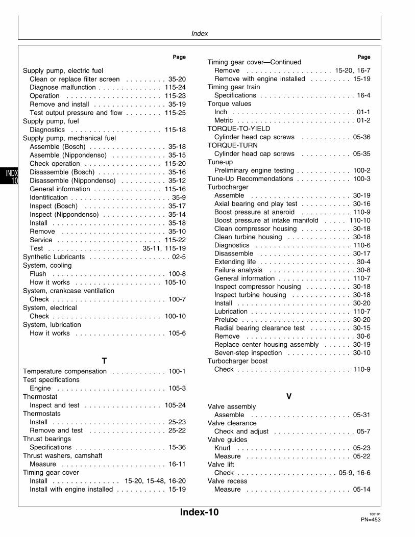
Page
Supply pump, electric fuelClean or replace filter screen . . . . . . . . . 35-20Diagnose malfunction . . . . . . . . . . . . . . 115-24Operation . . . . . . . . . . . . . . . . . . . . . 115-23Remove and install . . . . . . . . . . . . . . . . 35-19Test output pressure and flow . . . . . . . . 115-25
Supply pump, fuelDiagnostics . . . . . . . . . . . . . . . . . . . . 115-18
Supply pump, mechanical fuelAssemble (Bosch) . . . . . . . . . . . . . . . . . 35-18Assemble (Nippondenso) . . . . . . . . . . . . 35-15Check operation . . . . . . . . . . . . . . . . . 115-20Disassemble (Bosch) . . . . . . . . . . . . . . . 35-16Disassemble (Nippondenso) . . . . . . . . . . 35-12General information . . . . . . . . . . . . . . . 115-16Identification . . . . . . . . . . . . . . . . . . . . . . 35-9Inspect (Bosch) . . . . . . . . . . . . . . . . . . 35-17Inspect (Nippondenso) . . . . . . . . . . . . . . 35-14Install . . . . . . . . . . . . . . . . . . . . . . . . . 35-18Remove . . . . . . . . . . . . . . . . . . . . . . . 35-10Service . . . . . . . . . . . . . . . . . . . . . . . 115-22Test . . . . . . . . . . . . . . . . . . . . 35-11, 115-19
Synthetic Lubricants . . . . . . . . . . . . . . . . . . 02-5System, cooling
Flush . . . . . . . . . . . . . . . . . . . . . . . . . 100-8How it works . . . . . . . . . . . . . . . . . . . 105-10
System, crankcase ventilationCheck . . . . . . . . . . . . . . . . . . . . . . . . . 100-7
System, electricalCheck . . . . . . . . . . . . . . . . . . . . . . . . 100-10
System, lubricationHow it works . . . . . . . . . . . . . . . . . . . . 105-6
TTemperature compensation . . . . . . . . . . . . 100-1Test specifications
Engine . . . . . . . . . . . . . . . . . . . . . . . . 105-3Thermostat
Inspect and test . . . . . . . . . . . . . . . . . 105-24Thermostats
Install . . . . . . . . . . . . . . . . . . . . . . . . . 25-23Remove and test . . . . . . . . . . . . . . . . . 25-22
Thrust bearingsSpecifications . . . . . . . . . . . . . . . . . . . . 15-36
Thrust washers, camshaftMeasure . . . . . . . . . . . . . . . . . . . . . . . 16-11
Timing gear coverInstall . . . . . . . . . . . . . . . 15-20, 15-48, 16-20Install with engine installed . . . . . . . . . . . 15-19
PageTiming gear cover—Continued
Remove . . . . . . . . . . . . . . . . . . . 15-20, 16-7Remove with engine installed . . . . . . . . . 15-19
Timing gear trainSpecifications . . . . . . . . . . . . . . . . . . . . . 16-4
Torque valuesInch . . . . . . . . . . . . . . . . . . . . . . . . . . . 01-1Metric . . . . . . . . . . . . . . . . . . . . . . . . . . 01-2
TORQUE-TO-YIELDCylinder head cap screws . . . . . . . . . . . 05-36
TORQUE-TURNCylinder head cap screws . . . . . . . . . . . 05-35
Tune-upPreliminary engine testing . . . . . . . . . . . . 100-2
Tune-Up Recommendations . . . . . . . . . . . . 100-3Turbocharger
Assemble . . . . . . . . . . . . . . . . . . . . . . 30-19Axial bearing end play test . . . . . . . . . . . 30-16Boost pressure at aneroid . . . . . . . . . . . 110-9Boost pressure at intake manifold . . . . . 110-10Clean compressor housing . . . . . . . . . . . 30-18Clean turbine housing . . . . . . . . . . . . . . 30-18Diagnostics . . . . . . . . . . . . . . . . . . . . . 110-6Disassemble . . . . . . . . . . . . . . . . . . . . 30-17Extending life . . . . . . . . . . . . . . . . . . . . . 30-4Failure analysis . . . . . . . . . . . . . . . . . . . 30-8General information . . . . . . . . . . . . . . . . 110-7Inspect compressor housing . . . . . . . . . . 30-18Inspect turbine housing . . . . . . . . . . . . . 30-18Install . . . . . . . . . . . . . . . . . . . . . . . . . 30-20Lubrication . . . . . . . . . . . . . . . . . . . . . . 110-7Prelube . . . . . . . . . . . . . . . . . . . . . . . . 30-20Radial bearing clearance test . . . . . . . . . 30-15Remove . . . . . . . . . . . . . . . . . . . . . . . . 30-6Replace center housing assembly . . . . . . 30-19Seven-step inspection . . . . . . . . . . . . . . 30-10
Turbocharger boostCheck . . . . . . . . . . . . . . . . . . . . . . . . . 110-9
VValve assembly
Assemble . . . . . . . . . . . . . . . . . . . . . . 05-31Valve clearance
Check and adjust . . . . . . . . . . . . . . . . . . 05-7Valve guides
Knurl . . . . . . . . . . . . . . . . . . . . . . . . . 05-23Measure . . . . . . . . . . . . . . . . . . . . . . . 05-22
Valve liftCheck . . . . . . . . . . . . . . . . . . . . . . 05-9, 16-6
Valve recessMeasure . . . . . . . . . . . . . . . . . . . . . . . 05-14
Index
Index-10 160101
PN=453
INDX10
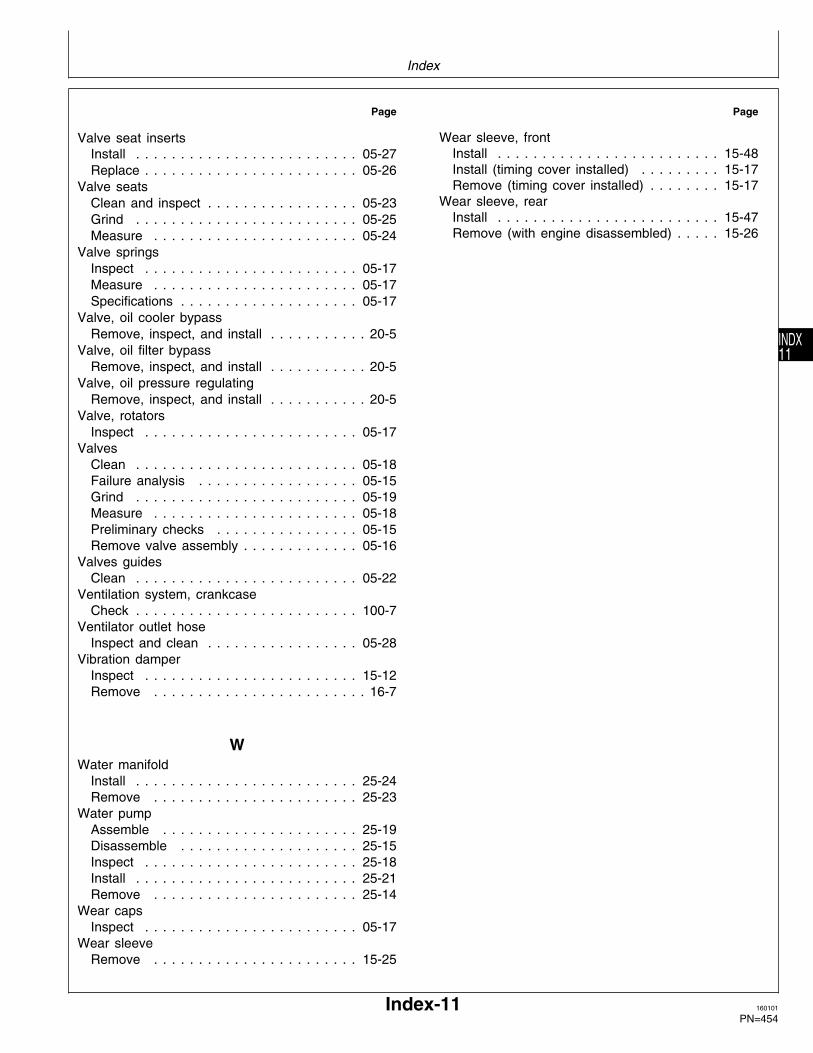
Page
Valve seat insertsInstall . . . . . . . . . . . . . . . . . . . . . . . . . 05-27Replace . . . . . . . . . . . . . . . . . . . . . . . . 05-26
Valve seatsClean and inspect . . . . . . . . . . . . . . . . . 05-23Grind . . . . . . . . . . . . . . . . . . . . . . . . . 05-25Measure . . . . . . . . . . . . . . . . . . . . . . . 05-24
Valve springsInspect . . . . . . . . . . . . . . . . . . . . . . . . 05-17Measure . . . . . . . . . . . . . . . . . . . . . . . 05-17Specifications . . . . . . . . . . . . . . . . . . . . 05-17
Valve, oil cooler bypassRemove, inspect, and install . . . . . . . . . . . 20-5
Valve, oil filter bypassRemove, inspect, and install . . . . . . . . . . . 20-5
Valve, oil pressure regulatingRemove, inspect, and install . . . . . . . . . . . 20-5
Valve, rotatorsInspect . . . . . . . . . . . . . . . . . . . . . . . . 05-17
ValvesClean . . . . . . . . . . . . . . . . . . . . . . . . . 05-18Failure analysis . . . . . . . . . . . . . . . . . . 05-15Grind . . . . . . . . . . . . . . . . . . . . . . . . . 05-19Measure . . . . . . . . . . . . . . . . . . . . . . . 05-18Preliminary checks . . . . . . . . . . . . . . . . 05-15Remove valve assembly . . . . . . . . . . . . . 05-16
Valves guidesClean . . . . . . . . . . . . . . . . . . . . . . . . . 05-22
Ventilation system, crankcaseCheck . . . . . . . . . . . . . . . . . . . . . . . . . 100-7
Ventilator outlet hoseInspect and clean . . . . . . . . . . . . . . . . . 05-28
Vibration damperInspect . . . . . . . . . . . . . . . . . . . . . . . . 15-12Remove . . . . . . . . . . . . . . . . . . . . . . . . 16-7
WWater manifold
Install . . . . . . . . . . . . . . . . . . . . . . . . . 25-24Remove . . . . . . . . . . . . . . . . . . . . . . . 25-23
Water pumpAssemble . . . . . . . . . . . . . . . . . . . . . . 25-19Disassemble . . . . . . . . . . . . . . . . . . . . 25-15Inspect . . . . . . . . . . . . . . . . . . . . . . . . 25-18Install . . . . . . . . . . . . . . . . . . . . . . . . . 25-21Remove . . . . . . . . . . . . . . . . . . . . . . . 25-14
Wear capsInspect . . . . . . . . . . . . . . . . . . . . . . . . 05-17
Wear sleeveRemove . . . . . . . . . . . . . . . . . . . . . . . 15-25
Page
Wear sleeve, frontInstall . . . . . . . . . . . . . . . . . . . . . . . . . 15-48Install (timing cover installed) . . . . . . . . . 15-17Remove (timing cover installed) . . . . . . . . 15-17
Wear sleeve, rearInstall . . . . . . . . . . . . . . . . . . . . . . . . . 15-47Remove (with engine disassembled) . . . . . 15-26
Index
Index-11 160101
PN=454
INDX11

Index
Index-12 160101
PN=455
INDX12


![[XLS]reports.mca.gov.inreports.mca.gov.in/Reports/MasterDataExcels/company... · Web view500000 500000 500000 500000 100000 100000 100000 100000 100000 100000 100000 100000 100000](https://static.fdocuments.in/doc/165x107/5b2c80367f8b9a3d348b8549/xls-web-view500000-500000-500000-500000-100000-100000-100000-100000-100000.jpg)
![[XLS] · Web view100000 100000. 100000 100000. 100000 100000. 200000 100000. 500000 200000. 100000 3000. 500000 200000. 500000 700. 500000 70.](https://static.fdocuments.in/doc/165x107/5ab577a37f8b9a2f438c946c/xls-view100000-100000-100000-100000-100000-100000-200000-100000-500000-200000.jpg)


![[XLS] creditors list.xlsx · Web view1 97571010 9/4/2017 2 30000000 3 20000000 4 1200000 5 3000000 6 1000000 7 5000000 8 500000 9 210000 10 500000 11 500000 12 500000 13 355000 14](https://static.fdocuments.in/doc/165x107/5aaaeb467f8b9a6c188eda50/xls-creditors-listxlsxweb-view1-97571010-942017-2-30000000-3-20000000-4-1200000.jpg)


