Series 1400H - hunterheavyequipment · The mounting configuration shown is based on the Series...
16
product guide features • 127 ft (38.72 m) Five-Section Boom • 33 USt (29.9 t) Rating • Easy Glide Wear Pads • Internal Anti-two-block Series 1400H contents Features 2 Mounting Configurations 3 Specifications 4 Capacities 5 Accessories 11 Dimensions Specifications 12 *Product may be shown with optional equipment. www.manitowoccranegroup.com
Transcript of Series 1400H - hunterheavyequipment · The mounting configuration shown is based on the Series...

productguide
features• 127 ft (38.72 m) Five-Section Boom
• 33 USt (29.9 t) Rating
• Easy Glide Wear Pads
• Internal Anti-two-block
Series 1400H
contents
Features 2
Mounting Configurations 3
Specifications 4
Capacities 5
Accessories 11
Dimensions
Specifications 12
*Product may be shown with optional equipment.
www.manitowoccranegroup.com

features
2
Why Buy a National Crane Series 1400H?
1400
H
• 33 USt (29.9 t) maximum capacity
• 165 ft (50.3 m) maximum vertical reach*
• 135-ft (41.15-m) maximumvertical hydraulic reach*
• Load Moment Indicator system
• Proportional boom extension
• High performance planetary winch
• 99-gallon (375L) hydraulicreservoir with 10 micron returnfilter.
* Maximum vertical reach isground-level to boom tip heightat maximum extension andangle with outriggers/stabilizersfully extended.
• 33 USt (29.9 t) Rating – The 1400H is a 33 USt machine, an 18% increase in capacity over theSeries 1100.
• 127-foot (38.72 m) Five-Section Boom – The longest in its size range. The longer boom allowsthe operator to perform more lifts without the use of a jib, reducing setup time and improvingefficiency. A 100-foot (30.5 m) four-section boom or a 110-foot (33.5 m) four-section boom is alsoavailable.
• Overload Protection – All National cranes are equipped with overload protection:– Load Moment Indicator (LMI) standard on all series 1400H machines.– LCD display is visible in full or low light.– All crane load lifting values are displayed simultaneously.
• Easy Glide Boom Wear Pads – Reduce the conditions that cause boom chatter and vibration.The net result is smoother crane operation.
• Rotation – 375 ˚ non-continuous rotation is standard, with an option for 360 ˚ continuous rotation.
• Internal Anti-two-block Wire – This exclusive design, standard on the Series 1400H, routes thewiring through the inside of the boom. No more snagging the wire on obstructions.
• Crossframe Outriggers – Mainframe outriggers are crossframe H-style, with 24'6" (7.47 m) span,with mid-span setting of 18'6" (5.64 m). Rear stabilizers are H-style with 18'6" (5.64 m) span.Removable ball-and-socket aluminum outrigger pads on mainframe outriggers.
• Adjustable Swing Speed – Standard on the 1400H. A control knob located on the swing motorbrake release valve can be easily adjusted to the crane operator’s swing speed preference.
• Heavier-duty Torsion Box – The stronger standard torsion box improves rigidity, reduces truckframe flex and reduces the need for counterweight.
• Speedy-reeve Boom Tip and Sheave Blocks – These standard features simplify riggingchanges by decreasing the time needed to change line reeving.
• Pre-painted Components – Painting crane components before assembly reduces the possibilityof rust, improves serviceability and enhances the appearance of the machine.
• Oil Cooler – Radiator mounted on truck frame with electric fan is standard, with an option todeduct the cooler for low duty-cycle applications.
• Improved Serviceability –– Bearings on the boom extend and retract cables can be greased through access holes in the
boom side plates. – Number of internal boom parts has been reduced, decreasing service time when rebuilding the
machine.
• Triple Pump Hydraulics – Direct mount triple pump hydraulics.
• National Crane Is the Market Leader – National is number one in the production of commercialtruck-mounted boom trucks. National has many programs and people directly and indirectlyinvolved to provide our customers reliable products.
– National has the boom truck industry’s leading test program. Every structural part of the craneis cycle tested up to 60,000 cycles at full capacity. In addition to cycle testing, each model issubjected to state-of-the-art strain gauge testing that measures metal deformation as small asone one-millionth of an inch. The net result is that any weak areas are caught in test, not on jobsites where costly downtime occurs.
– Parts are available for all National Crane models for the life of the crane.
– National has a formalized quality program and is ISO 9001 approved.
• National Crane’s Quality Management System is ISO 9001:2000 Approved.
– National is number one in the production of commercial truck-mounted boom trucks and hasmany programs and people directly and indirectly involved to provide our customers withreliable products.
• Electronic versions of manuals available through Manitowoc Crane CARE.
*Product may be shown with optional equipment.

3
1400
H
mounting configuration
The mounting configuration shown is based on the Series 1400H with an 85% stability factor. The complete unitmust be installed in accordance with factory requirements and a test performed to determine actual stability andcounterweight requirements since individual truck chassis vary. If bare truck weights are not met, counterweightwill be required. The front bumper stabilizer (SFO) is required for all installations. Chassis must be equipped witha front frame extension suitable for SFO addition. Contact factory for complete chassis specifications.
Working area ...........................................................................................................................................................360°Gross Axle Weight Rating Front.....................................................................................................20,000 lb (9072 kg)*Gross Axle Weight Rating Rear ...................................................................................................40,000 lb (18 144 kg)*Gross Vehicle Weight Rating .......................................................................................................60,000 lb (27 216 kg)*Wheelbase..............................................................................................................................Minimum 268 in (681 cm)Cab to Axle/trunnion (CA/CT) ................................................................................................Minimum 240 in (518 cm)After Frame (AF) ....................................................................................................................120 in (305 cm) minimumFrame Section Modulus (SM), front axle to end of afterframe, w/110,000 PSI (758 MPa) ...................30 in3 (492 cm3)Stability Weight, Front .....................................................................................................9,250 lb (4196 kg) minimum**Stability Weight, Rear.......................................................................................................8,100 lb (3674 kg) minimum**Estimated Average Final Weight ...............................................................................................51,500 lb (23 360 kg)***
The diagram shows the 360° working area that can be achieved with the front stabilizer (standard on the Series1400H). The front stabilizer is required when extending the boom and lifting loads forward of the outriggers. Aminimum of 10-in3 (164 cm3) section modulus at 110,000 psi (759 MPa) is required from the rear of the front springhanger forward to the front stabilizer. Integral front frame extension required.
* Required to mount basic crane with 30-ft (9.15-m) jib option. Additional options or heavier bare chassis weights will require additionalaxles or a GVWR in excess of 60,000 lb (27 216 kg); in some states, special permits for overload are required.
** Estimated axle scale weights prior to installation of crane, stabilizers and subbase for 85% stability.
*** Includes basic crane without jib, 100-gal (379-L) fuel tank, 22' wood flatbed, hydraulic pump & PTO, rear bumper, rear stabilizer,boom rest, and two workers (300 lb, 136kg) in cab.
Note: Chassis will require integral extended front frame rails for SFO addition.
Notes:• Gross Vehicle Weight Rating (GVWR) is dependent on all
components of the vehicle (axles, tires, springs, frame, etc.) meetingmanufacturers’ recommendations; always specify GVWR whenpurchasing trucks.
• Diesel engines require a variable speed governor and energize-to-runfuel solenoid for smooth crane operation. Electronic fuel-injectedengines are required.
• All mounting data is based on a National Series 1400H with thestandard subbase and an 85 percent stability factor.
• The complete unit must be installed in accordance with factoryrequirements, and a test performed to determine actual stability andcounterweight requirements per SAE J765; contact the factory fordetails.
• Transmission neutral safety interlock switch is required.
113"(287 cm)
MIN
SFO
64"(163 cm)
MIN
204"(518 cm)
MIN 8,100 lb(3,674 kg)
RSOD3" (7.6 cm) MIN
*9,250 lb(4,196 kg)
360oFULL CAPACITY
WORK AREA
TRUCK REQUIREMENTS

4
1400
Hspecifications
Boom and Jib Combinations Data
1400A Winch Data
Available in three basic models.
Model 1469H — Equipped with a 31 ft-69 ft five section boom.
Model 14100H — Equipped with a 30 ft 10 in to 100 ft (9.40-30.49 m) four-section boom. This model can be equipped with a 30 ft (9.15 m)single-section jib or a 30-54 ft (9.15-16.46 m) two-section jib. Maximum tip height w/30ft (9.15 m) jib is 137 ft (41.77 m), while maximum tipheight w/30-54 ft (9.15-16.46 m) jib is 161 ft (49.08 m).
14FJ54M 30-54 ft (9.15-16.46 m) two-section jib 30'10" - 100' (9.40-30.49 m) four-section boom
14FJ30M 30 ft (9.15 m) single-section jib30'10" - 100' (9.40-30.49 m) four-section boom
MAXIMUM BOOM LENGTH AT MAXIMUMELEVATION WITH RIGGING SHOWN 127’ 110’ 83’ 64’ 52’ 43’ 36’ 31’WITH LOAD BLOCK AT GROUND LEVEL boom w/ 54’ jib
Average Cable Breaking Lift and Lift and Lift and Lift and Lift and Lift and Lift and Lift and
Winch Supplied Strength Speed Speed Speed Speed Speed Speed Speed Speed
Standard 5/8" DiameterPlanetary Rotation 45,400 lb 9,000 lb (4082 kg) 18,000 lb (8165 kg) 27,000 lb (12 247 kg) 36,000 lb (16 329 kg) 45,000 lb (20 412 kg) 54,000 lb (24 494 kg) 63,000 lb (28 576 kg) 66,000 lb (29 937 kg)
Winch Resistant (20 593 kg) 170 fpm (52 m/min) 85 fpm (26 m/min) 57 fpm (17 m/min) 43 fpm (13 m/min) 34 fpm (10 m/min) 28 fpm (9 m/min) 24 fpm (7 m/min) 21 fpm (6 m/min)Low
SpeedStandard 5/8" DiameterPlanetary Rotation 45,400 lb 4,400 lb (1996 kg) 8,800 lb (3992 kg) 13,200 lb (5987 kg) 17,600 lb (7983 kg) 22,000 lb (9979 kg) 26,400 lb (11 975 kg) 30,800 lb (13 971 kg) 35,200 lb (15 967 kg)
Winch Resistant (20 593 kg) 340 fpm (104 m/min) 170 fpm (52 m/min) 113 fpm (34 m/min) 85 fpm (26 m/min) 68 fpm (21 m/min) 57 fpm (17 m/min) 49 fpm (15 m/min) 43 fpm (13 m/min)High
Speed
1 Part Line 2 Part Line 3 Part Line 4 Part Line 5 Part Line 6 Part Line 7 Part Line• Do not deadhead line block againstboom tip when extending boom.
• Keep at least 3 wraps of loadlineon drum at all times.
• Use only 5/8” diameter rotation-resistant cable with 45,400 poundsbreaking strength on this machine.
8 Part Line
Block Type Rating WeightAux. Boom Head 100 lb (45 kg)Downhaul Weight 5 Ton (4.53t) 180 lb (82 kg)1 Sheave Block 15 Ton (13.60t) 375 lb (170 kg)2 Sheave Block 25 Ton (22.67t) 640 lb (290 kg)3 Sheave Block 35 Ton (31.74t) 870 lb (395 kg)4 Sheave Block 36 Ton (32.65) 970 lb (440 kg)
All winch pulls and speeds in this chart are shown on the fourth layer. Winch line pulls would increase on the first, second and third layers. Winch line speed would decrease on the first, second and third layers. Winch line pulls may be limited by the winch capacity or the ANSI 5 to 1 cable safety factor. These are shown below:
Winch Full Drum Pull Allowable Cable PullStandard planetary 4,400 lb. (1996 kg) (high speed) 9,080 lb. (4119 kg)
9,000 lb. (4082 kg) (low speed)
Model 14127H — Equipped with a 31 ft 7 in to 127 ft (9.63-38.72 m) five-section boom. This model can be equipped with a 30 ft (9.15 m) single-section jib. Maximum tip height w/ 30 ft (9.15 m) jib is 164 ft (50.00 m).
Note: maximum tip height is measured with outriggers/stabilizers fully extended.
31'7" - 127' (9.63-38.72 m) five-section boom 14FJ30M 30 ft (9.15 m) single-section jib
23 FTBOOM
(LB)
LOADEDBOOMANGLE(DEG)
A34 FT
BOOM(LB)
LOADEDBOOMANGLE(DEG)
B46 FT
BOOM(LB)
LOADEDBOOMANGLE(DEG)
C58 FT
BOOM(LB)
LOADEDBOOMANGLE(DEG)
69 FTBOOM
(LB)
LOADEDBOOMANGLE(DEG)
LOADEDRADIUS
(FT)
68
1012141620253035404550556065
66,00060,05052,05046,00041,15036,95026,550
19,750
56,30048,35042,50038,00034,40028,95021,45015,450
12,150
46,10040,30035,85032,35027,15021,70015,75012,050
9,550
8,350
35,60032,55029,50024,95020,90015,90012,200
9,6507,9006,5505,500
5,450
25,70023,85021,20017,20015,10012,200
9,7007,9506,6005,5004,6503,9503,750
74.5696357504215
0
76.57369.565.561.552.54019
0
7875.5737064.557493925.5
0
79777570.56559.5534638.528.511
0
79.577.574.569.56560555043.536.52816
0
5
1400
H
capacities
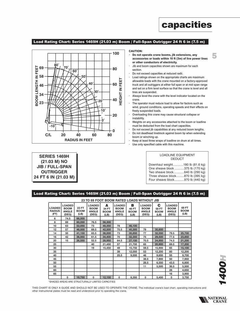
Load Rating Chart: Series 1469H (21.03 m) Boom / Full-Span Outrigger 24 ft 6 in (7.5 m)
Load Rating Chart: Series 1469H (21.03 m) Boom / Full-Span Outrigger 24 ft 6 in (7.5 m)
THIS CHART IS ONLY A GUIDE AND SHOULD NOT BE USED TO OPERATE THE CRANE. The individual crane’s load chart, operating instructions andother instructional plates must be read and understood prior to operating the crane.
RADIUS IN FEET
HE
IGH
TIN
FE
ET
BO
OM
LE
NG
TH
INF
EE
T
C/L 20
23
34
46
58
69
40 60 800
20
40
60
80
100
0˚
-10˚
10˚
20˚
30˚
50˚
60˚70˚
80˚
40˚
CAUTION:• Do not operate crane booms, jib extensions, any
accessories or loads within 10 ft (3m) of live power linesor other conductors of electricity.
• Jib and boom capacities shown are maximum for eachsection.
• Do not exceed capacities at reduced radii.• Load ratings shown on the appropriate charts are maximum
allowable loads with the crane mounted on a factory-approvedtruck and all outriggers at either full span or at mid span rangeand set on a firm level surface so that the crane is level and alltires are suspended.
• Always level the crane with the level indicator located on thecrane.
• The operator must reduce load to allow for factors such aswind, ground conditions, operating speeds and their effects onfreely suspended loads.
• Overloading this crane may cause structural collapse orinstability.
• Weights on any accessories attached to the boom or loadlinemust be deducted from the load chart capacities.
• Do not exceed jib capabilities at any reduced boom lengths.• Do not deadhead lineblock against boom tip when extending
boom or winching up.• Keep at least three wraps of loadline on drum at all times.• Use only specified cable with this machine.
SERIES 1469H(21.03 M) NO
JIB / FULL-SPANOUTRIGGER
24 FT 6 IN (21.03 M)
LOADLINE EQUIPMENTDEDUCT
Downhaul weight............180 lb (81.6 kg)One sheave block ...........375 lb (170 kg)Two sheave block............640 lb (290 kg)Three sheave block.........870 lb (395 kg)Four sheave block...........970 lb (440 kg)
23 TO 69 FOOT BOOM RATED LOADS WITHOUT JIB
*SHADED AREAS ARE STRUCTURALLY LIMITED CAPACITIES

6
1400
Hcapacities
THIS CHART IS ONLY A GUIDE AND SHOULD NOT BE USED TO OPERATE THE CRANE. The individual crane’s load chart, operating instructions andother instructional plates must be read and understood prior to operating the crane.
Load Rating Chart: Series 1469H (21.03 m) Boom / Mid-Span Outrigger 18 in 6 in (5.63 m)
Load Rating Chart: Series 1469H (21.03 m) Boom / Mid-Span Outrigger 18 in 6 in (5.63 m)
RADIUS IN FEET
HE
IGH
TIN
FEE
T
BO
OM
LEN
GT
HIN
FEE
T
C/L 20
23
34
46
58
69
40 60 800
20
40
60
80
100
0˚
-10˚
10˚
20˚
30˚
50˚
60˚70˚
80˚
40˚
23 FTBOOM
(LB)
LOADEDBOOMANGLE(DEG)
A34 FT
BOOM(LB)
LOADEDBOOMANGLE(DEG)
B46 FT
BOOM(LB)
LOADEDBOOMANGLE(DEG)
C58 FT
BOOM(LB)
LOADEDBOOMANGLE(DEG)
69 FTBOOM
(LB)
LOADEDBOOMANGLE(DEG)
LOADEDRADIUS
(FT)
681012141620253035404550556065
66,00060,05052,05046,00041,15034,72021,950
19,750
56,30048,35042,50038,00034,40022,45014,85010,650
9,700
46,10040,30035,85032,35022,80015,10010,9008,1006,200
5,250
35,60032,55029,50022,95015,30011,0508,2506,3505,0003,9003,100
3,050
25,70023,85021,20015,35011,1008,3506,4505,0504,0003,1502,5001,9501,800
74.5696357504215
0
76.57369.565.561.55339.519
0
7875.5737064.557483926.5
0
79777570.565595346382810.5
0
79.577.574.57064.5605549.543.5362814.50
CAUTION:• Do not operate crane booms, jib extensions, any
accessories or loads within 10 ft (3m) of live power linesor other conductors of electricity.
• Jib and boom capacities shown are maximum for each section.• Do not exceed capacities at reduced radii.• Load ratings shown on the load rating charts are maximum
allowable loads with the outriggers properly extended and theoutrigger lock pins engaged on a firm, level surface and thecrane leveled and mounted on a factory recommended truck.
• Always level the crane with the level indicator located on thecrane.
• The operator must reduce load to allow for factors such aswind, ground conditions, operating speeds and their effects onfreely suspended loads.
• Overloading this crane may cause structural collapse orinstability.
• Weights on any accessories attached to the boom or loadlinemust be deducted from the load chart capacities.
• Do not exceed jib capabilities at any reduced boom lengths.• Do not deadhead lineblock against boom tip when extending
boom or winching up.• Keep at least three wraps of loadline on drum at all times.• Use only specified cable with this machine.
SERIES 1469H(21.03 M) NO JIB /
MID-SPANOUTRIGGER
18 FT 6 IN (5.63 M)
LOADLINE EQUIPMENTDEDUCT
Downhaul weight.............180 lb (81.6 kg)One sheave block ............375 lb (170 kg)Two sheave block.............640 lb (290 kg)Three sheave block..........870 lb (395 kg)Four sheave block............970 lb (440 kg)
23 to 69 Foot Boom Rated Loads without Jib
*SHADED AREAS ARE STRUCTURALLY LIMITED CAPACITIES

7
1400
H
68
10121416202530354045505560657075808590
79.174.970.666.361.756.84627.4
0
66,00049,20042,20038,60034,20030,35023,55016,700
11,400
800
LOADRADIUS(FEET)
LOADEDBOOMANGLE
30FTBOOM
(lb)
LOADEDBOOMANGLE
A44FT
BOOM(lb)
LOADEDBOOMANGLE
LOADEDBOOMANGLE
100FTBOOM
(lb)
LOADEDBOOMANGLE
54FTJIB(lb)
LOADEDBOOMANGLE
LOADEDBOOMANGLE
ADD TOCAPACITIES
WHEN NO JIBSTOWED (lb)
LOADEDBOOMANGLE
30FTJIB(lb)
77.274.972.169.263.355.246.13520
0
37,90033,40029,40026,90021,40017,40013,90010,3508,000
7,300
600
79.277.175.170.865.359.553.146.838.82912.3
0
29,55026,55024,55019,25016,05013,55010,6508,2506,5005,1504,150
4,000
450
8078.675.37166.761.957.652.446.740.433.223.8
0
23,05021,05018,05014,65012,55010,5508,4006,6505,3004,2503,4002,750
1850
350
78.474.971.367.764.360.155.951.546.741.535.728.819.6
0
16,80013,70011,450
9,9008,5506,7505,4004,4003,5502,8502,2501,7501,350
900
300
8077.374.571.868.465.361.958.354.650.746.642.237.331.825.2
11,60010,95010,550
9,1508,0506,8505,5004,4503,6002,9002,3001,8001,4001,050
700
250
78.476.574.672.470.167.865.562.759.957.154.151.147.944.5
5,5005,4505,4005,1004,6004,2503,9003,2002,6002,0501,6501,250
950650
78.576.975.273.471.669.867.9666461.859.657.454.852.249.446.6
2,6502,6002,5002,4002,3002,2002,1002,0001,8501,7501,6001,5001,200
950700500
LOADRADIUS(FEET)
3035404550556065707580859095
100105110
B58FT
BOOM(lb)
C72FT
BOOM(lb)
D86FT
BOOM(lb)
capacities
Load Rating Chart: Series 14100H (30.5 m) Boom with 30-54 ft (9.1-16.45 m) Jib / Full-Span Outrigger 24 ft 6 in (7.5 m)
Load Rating Chart: Series 14100H (30.5 m) Boom with 30-54 ft (9.1-16.45 m) Jib / Full-Span Outrigger 24 ft 6 in (7.5 m)
THIS CHART IS ONLY A GUIDE AND SHOULD NOT BE USED TO OPERATE THE CRANE. The individual crane’s load chart, operating instructions andother instructional plates must be read and understood prior to operating the crane.
C/L 10
Operating radius from C/L rotationin feet with unloaded boom
001040302 906050 70 80
Structural limit linewith 54' jib deployed
110
Structural limit line with 30' jib deployed
30
44
58
72
86
100
130
BO
OM
LEN
GT
HIN
FE
ET
Structurallimit linewith 180 lbblock
80°75°
70°
65°
60°
55°
50°
45°
40°
35°
30°
25°
20°
15°
0°
5°
10°
Structurallimit linewith 180 lbblock
154
43°
-10°
42°
Structurallimit line with180 lb block
10
170
160
150
140
130
120
110
100
90
80
70
60
50
40
30
20
HO
OK
ELE
VAT
ION
INF
EE
T
CAUTION:• Do not operate crane booms, jib extensions, any
accessories or loads within 10 ft (3m) of live power linesor other conductors of electricity.
• Jib and boom capacities shown are maximum for eachsection.
• Do not exceed capacities at reduced radii.• Load ratings shown on the appropriate charts are maximum
allowable loads with the crane mounted on a factory-approvedtruck and all outriggers at either full span or at mid span rangeand set on a firm level surface so that the crane is level and alltires are suspended.
• Always level the crane with the level indicator located on thecrane.
• The operator must reduce load to allow for factors such aswind, ground conditions, operating speeds and their effects onfreely suspended loads.
• Overloading this crane may cause structural collapse orinstability.
• Weights on any accessories attached to the boom or loadlinemust be deducted from the load chart capacities.
• Do not exceed jib capabilities at any reduced boom lengths.• Do not deadhead lineblock against boom tip when extending
boom or winching up.• Keep at least three wraps of loadline on drum at all times.• Use only specified cable with this machine.
SERIES 14100HWITH
30-54 FT (9.1-16.45 M)
JIB / FULL-SPANOUTRIGGER
24 FT 6 IN (7.5 M)
NOTE:1. Operate with jib by radius when main
boom is fully extended. If necessaryincrease boom angle to maintain loadedradius.
2. Operate with jib by boom angle whenmain boom is not fully extended. Do notexceed rated jib capacities at anyreduced boom lengths.
LOADLINE EQUIPMENTDEDUCT
Downhaul weight............180 lb (81.6 kg)One sheave block ...........375 lb (170 kg)Two sheave block............640 lb (290 kg)Three sheave block.........870 lb (395 kg)Four sheave block...........970 lb (440 kg)
*SHADED AREAS ARE STRUCTURALLY LIMITED CAPACITIES

8
1400
Hcapacities
THIS CHART IS ONLY A GUIDE AND SHOULD NOT BE USED TO OPERATE THE CRANE. The individual crane’s load chart, operating instructions andother instructional plates must be read and understood prior to operating the crane.
Load Rating Chart: Series 14100H (33.5 m) Boom With 30-54 ft (9.1-16.45 m) Jib / Mid-Span Outrigger 18 ft 6 in (5.63 m)
Load Rating Chart: Series 14100H (33.5 m) Boom With 30-54 ft (9.1-16.45 m) Jib / Mid-Span Outrigger 18 ft 6 in (5.63 m)
90
Structural limit linewith 54' jib deployed
Structural limit line with 30' jib deployed
Structural limit linewith 180 lb block
55°
50°
45°
30°
25°
20°
15°
0°
5°
10°
Structural limit linewith 180 lb block
53°
Structural limit linewith 180 lb block
C/L 10Operating radius from C/L rotation
in feet with unloaded boom
20 30 40 6050 70 80
40°
35°
-10°
80°75°
70°
65°
60°
30
44
58
72
86
100
130
BO
OM
LEN
GT
HIN
FE
ET
154
10
170
160
150
140
130
120
110
100
90
80
70
60
50
40
30
20
HO
OK
ELE
VAT
ION
INF
EE
T
C72FT
BOOM(lb)
ADD TOCAPACITIES
WHEN NO JIBSTOWED (lb)
68
101214162025303540455055606570
79.174.970.666.361.756.845.927.4
0
58,60049,20042,20038,60034,20030,35019,65012,450
10,000
800
77.274.972.169.263.254.945.835.719.4
0
37,90033,40029,40026,90020,40013,150
9,1506,5504,850
4,650
600
79.277.175.170.865.159.55346.638.728.812
0
29,55026,55024,55019,25013,450
9,4506,8505,1503,8502,8502,050
1,850
450
78.576.975.273.471.669.867.965.56360.658.1
2,6502,6002,5002,4002,3002,2002,0501,6001,200
850550
78.476.574.672.169.566.864.261.558.755.8
5,5005,4505,4004,4503,4502,6501,9501,400
950600
8077.374.271.46864.661.157.653.950.146
11,60010,950
9,8507,2505,4504,1503,1502,3501,7001,200
750
250
78.474.971.167.563.659.555.350.946.14135.2
16,80013,7009,7007,1005,4004,1003,1002,3001,6501,150
700
300
80.278.675.370.966.36257.151.946.24032.723.4
0
23,05021,05018,05013,600
9,5507,0005,3004,0003,0002,2001,5501,050
850
350
LOADRADIUS(FEET)
LOADEDBOOMANGLE
30FTBOOM
(lb)
LOADEDBOOMANGLE
A44FT
BOOM(lb)
LOADEDBOOMANGLE
LOADEDBOOMANGLE
100FTBOOM
(lb)
LOADEDBOOMANGLE
54FTJIB(lb)
LOADEDBOOMANGLE
LOADEDBOOMANGLE
LOADEDBOOMANGLE
30FTJIB(lb)
LOADRADIUS(FEET)
B58FT
BOOM(lb)
D86FT
BOOM(lb)
303540455055606570758085
CAUTION:• Do not operate crane booms, jib extensions, any
accessories or loads within 10 ft (3m) of live power linesor other conductors of electricity.
• Jib and boom capacities shown are maximum for each section.• Do not exceed capacities at reduced radii.• Load ratings shown on the load rating charts are maximum
allowable loads with the outriggers properly extended and theoutrigger lock pins engaged on a firm, level surface and thecrane leveled and mounted on a factory recommended truck.
• Always level the crane with the level indicator located on thecrane.
• The operator must reduce load to allow for factors such aswind, ground conditions, operating speeds and their effects onfreely suspended loads.
• Overloading this crane may cause structural collapse orinstability.
• Weights on any accessories attached to the boom or loadlinemust be deducted from the load chart capacities.
• Do not exceed jib capabilities at any reduced boom lengths.• Do not deadhead lineblock against boom tip when extending
boom or winching up.• Keep at least three wraps of loadline on drum at all times.• Use only specified cable with this machine.
SERIES 14100HBOOM WITH
30-54 FT (9.1-16.45 M)
JIB / MID-SPANOUTRIGGER
18 FT 6 IN (5.63 M)
LOADLINE EQUIPMENTDEDUCT
Downhaul weight.............180 lb (81.6 kg)One sheave block ............375 lb (170 kg)Two sheave block.............640 lb (290 kg)Three sheave block..........870 lb (395 kg)Four sheave block............970 lb (440 kg)
*SHADED AREAS ARE STRUCTURALLY LIMITED CAPACITIES
NOTE:1. Operate with jib by radius when main
boom is fully extended. If necessaryincrease boom angle to maintain loadedradius.
2. Operate with jib by boom angle whenmain boom is not fully extended. Do notexceed rated jib capacities at anyreduced boom lengths.

C89FT
BOOM(lb)
78.176.173.669.867.864.661.457.454.651.147.343.238.9
68
101215202530354045505560657075808590
79.97671.967.761.149.533.1
0
66,00047,55040,75035,80030,20023,95017,700
12,150
500
LOADRADIUS(FEET)
LOADEDBOOMANGLE
31FTBOOM
(lb)
LOADEDBOOMANGLE
A51FT
BOOM(lb)
LOADEDBOOMANGLE
LOADEDBOOMANGLE
127FTBOOM
(lb)
LOADEDBOOMANGLE
30FTJIB(lb)
LOADEDBOOMANGLE
LOADEDBOOMANGLE
79.777.472.867.761.254.146.236.525.7
0
32,70029,75025,90020,45016,75014,00010,550
8,1006,250
4,800
300
78.174.870.465.961.155.250.94538.329.819.1
0
22,55018,95015,35012,85010,650
8,3506,5005,1004,0003,1502,400
2,000
250
78.874.772.268.664.361.557.453.248.14438.732.624.514
0
16,60014,20011,850
9,7008,3006,7005,3004,2003,3002,6002,0001,4501,000
650
500
200
12,25010,550
9,0507,8506,7505,4004,3003,4002,7002,1001,5501,100
750
150
80.378.576.473.871.569.566.863.661.358.455.552.249.445.6
8,2007,9007,6007,2006,4005,5004,4003,5002,8002,1501,6501,200
800500
100
79.979.177.575.974.272.570.768.966.464.462.159.757.354.8
3,9003,8503,7003,5503,4003,2503,1002,9502,6002,0501,6001,200
850550
ADD TOCAPACITIES
WHEN NO JIBSTOWED (lb)
LOADRADIUS(FEET)
3035404550556065707580859095
B70FT
BOOM(lb)
D108FTBOOM
(lb)
9
1400
H
capacities
Load Rating Chart: Series 14127H (38.7 m) Boom With 30-54 ft (9.1-16.45 m) Jib / Full-Span Outrigger 24 ft 6 in (7.5 m)
Load Rating Chart: Series 14127H (38.7 m) Boom With 30-54 ft (9.1-16.45 m) Jib / Full-Span Outrigger 24 ft 6 in (7.5 m)
THIS CHART IS ONLY A GUIDE AND SHOULD NOT BE USED TO OPERATE THE CRANE. The individual crane’s load chart, operating instructions andother instructional plates must be read and understood prior to operating the crane.
CAUTION:• Do not operate crane booms, jib extensions, any
accessories or loads within 10 ft (3m) of live power lines orother conductors of electricity.
• Jib and boom capacities shown are maximum for each section.• Do not exceed capacities at reduced radii.• Load ratings shown on the appropriate charts are maximum
allowable loads with the crane mounted on a factory-approvedtruck and all outriggers at either full span or at mid span rangeand set on a firm level surface so that the crane is level and alltires are suspended.
• Always level the crane with the level indicator located on thecrane.
• The operator must reduce load to allow for factors such as wind,ground conditions, operating speeds and their effects on freelysuspended loads.
• Overloading this crane may cause structural collapse orinstability.
• Weights on any accessories attached to the boom or loadlinemust be deducted from the load chart capacities.
• Do not exceed jib capabilities at any reduced boom lengths.• Do not deadhead lineblock against boom tip when extending
boom or winching up.• Keep at least three wraps of loadline on drum at all times.• Use only specified cable with this machine.
SERIES 14127H(38.7 M) BOOMWITH 30-54 FT (9.1-16.45 M)
JIB / FULL-SPANOUTRIGGER
24 FT 6 IN (7.5 M)
NOTE:1. Operate with jib by radius when main
boom is fully extended. If necessaryincrease boom angle to maintain loadedradius.
2. Operate with jib by boom angle whenmain boom is not fully extended. Do notexceed rated jib capacities at anyreduced boom lengths.
LOADLINE EQUIPMENTDEDUCT
Downhaul weight............180 lb (81.6 kg)One sheave block ...........375 lb (170 kg)Two sheave block............640 lb (290 kg)Three sheave block.........870 lb (395 kg)Four sheave block...........970 lb (440 kg)
*SHADED AREAS ARE STRUCTURALLY LIMITED CAPACITIES
C/L 20 40 60 80 100
RADIUS IN FEET
0
20
40
60
80
100
120
140
160
HE
IGH
TIN
FEE
T
30' Jib
BO
OM
LEN
GT
HIN
FEE
T
70
108
127
89
31
51
C
B
A
D
80˚75˚
70˚65˚
60˚
50˚
45˚
52˚55˚
40˚
30˚
20˚
10˚
35˚
25˚
15˚
5˚
0˚
-10˚

10
1400
Hcapacities
THIS CHART IS ONLY A GUIDE AND SHOULD NOT BE USED TO OPERATE THE CRANE. The individual crane’s load chart, operating instructions andother instructional plates must be read and understood prior to operating the crane.
Load Rating Chart: Series 14127H (38.7 m) Boom With 30-54 ft (9.1-16.45 m) Jib / Mid-Span Outrigger 18 ft 6 in (5.63 m)
Load Rating Chart: Series 14127H (38.7 m) Boom With 30-54 ft (9.1-16.45 m) Jib / Mid-Span Outrigger 18 ft 6 in (5.63 m)
Structurallimit line with180 lb block.
Structural limitline with 30' jibdeployed.
C/L 20 40 60 80
RADIUS IN FEET
0
20
40
60
80
100
120
140
160
HE
IGH
TIN
FEE
T
30' Jib
BO
OM
LEN
GT
HIN
FEE
T
70
108
127
89
31
51
80˚75˚
70˚65˚
-10˚
60˚
50˚
45˚
63˚
55˚
40˚
30˚
20˚
10˚
35˚
25˚
15˚
5˚
0˚
Structurallimit line with180 lb block.
C
B
A
D
B70FT
BOOM(lb)
C89FT
BOOM(lb)
ADD TOCAPACITIES
WHEN NO JIBSTOWED (lb)
68
10121520253035404550556065
80.17671.967.861.248.933
0
58,80047,55040,75035,80030,20020,10012,550
8,200
500
79.777.473.867.76153.846.637.525.4
0
32,70029,75025,90020,45013,450
9,2506,6004,8003,450
2,900
300
7974.870.365.56155.950.544.537.929.918.7
22,55018,95013,8009,5506,8505,0503,7002,6501,8001,100
550
250
78.875.571.868.464.760.856.852.648.243.4
16,60014,0009,7507,0505,2503,9002,8502,0001,300
750
200
78.87673.170.16763.960.757.453.9
12,2509,9007,2005,4004,0002,9502,1001,400
850
150
80.478.576.473.771.168.465.863.160.4
8,2007,9007,3505,5004,1003,0502,2001,500
950
100
80.679.177.575.974.27269.767.465.1
3,9003,8503,7003,5503,4002,6501,9501,350
850
LOADRADIUS(FEET)
LOADEDBOOMANGLE
31FTBOOM
(lb)
LOADEDBOOMANGLE
A51FT
BOOM(lb)
LOADEDBOOMANGLE
LOADEDBOOMANGLE
127FTBOOM
(lb)
LOADEDBOOMANGLE
30FTJIB(lb)
LOADEDBOOMANGLE
LOADEDBOOMANGLE
LOADRADIUS(FEET)
D108FTBOOM
(lb)
303540455055606570
CAUTION:• Do not operate crane booms, jib extensions, any
accessories or loads within 10 ft (3m) of live power linesor other conductors of electricity.
• Jib and boom capacities shown are maximum for each section.• Do not exceed capacities at reduced radii.• Load ratings shown on the load rating charts are maximum
allowable loads with the outriggers properly extended and theoutrigger lock pins engaged on a firm, level surface and thecrane leveled and mounted on a factory recommended truck.
• Always level the crane with the level indicator located on thecrane.
• The operator must reduce load to allow for factors such aswind, ground conditions, operating speeds and their effects onfreely suspended loads.
• Overloading this crane may cause structural collapse orinstability.
• Weights on any accessories attached to the boom or loadlinemust be deducted from the load chart capacities.
• Do not exceed jib capabilities at any reduced boom lengths.• Do not deadhead lineblock against boom tip when extending
boom or winching up.• Keep at least three wraps of loadline on drum at all times.• Use only specified cable with this machine.
SERIES 14127H(38.7 M) BOOM WITH 30-54 FT (9.1-16.45 M)
JIB / MID-SPANOUTRIGGER
18 FT 6 IN (5.63 M)
LOADLINE EQUIPMENTDEDUCT
Downhaul weight.............180 lb (81.6 kg)One sheave block ............375 lb (170 kg)Two sheave block.............640 lb (290 kg)Three sheave block..........870 lb (395 kg)Four sheave block............970 lb (440 kg)
*SHADED AREAS ARE STRUCTURALLY LIMITED CAPACITIES
NOTE:1. Operate with jib by radius when main
boom is fully extended. If necessaryincrease boom angle to maintain loadedradius.
2. Operate with jib by boom angle whenmain boom is not fully extended. Do notexceed rated jib capacities at anyreduced boom lengths.

1400
H
accessories
THIS CHART IS ONLY A GUIDE AND SHOULD NOT BE USED TO OPERATE THE CRANE. The individual crane’s load chart, operating instructions andother instructional plates must be read and understood prior to operating the crane.
11
Radio Remote Controls –Eliminate the handling and maintenance concerns that accompany cabled remotes. Operate to a range of about 250 feet (76 m), varying with conditions. • NB4R
One-Person Basket –Strong but lightweight steel basket with 300-lb. (139-kg) capacity, gravity hung • B1-Swith swing lock and full body harness. • 2B1-S (for dual locking baskets)
Heavy-duty Personnel Basket –1,200-lb. (544-kg) capacity steel basket with safety loops for four passengers. Gravityleveling 72- x 42-inch (183- x 107-cm) platform. Fast attachment and secure locking • BSA-1systems. Load chart must show 2,300 lb. (1043 kg) minimum to operate this accessory. • BSA-R1 (provides rotation)
Air Conditioning –Back of cab mounted – self contained modular unit with in-cab cool air outlets. • ACRequires 130+ amp. chassis alternator.
Last Layer Indicator Option on winch with indicator in cab. • LLI
Winchdown Rotation Indicator –Has “thumper” in the cab winch lever to indicate to the operator that the winch • WDRJis in motion.
Outrigger Controls at operator’s seat in addition to ground controls. • ICORC
Hour MeterHour meter in truck cab to record crane operation hours. • HRM
Steel Tool Box Options
Spanish-Language Danger Decals, Control Knobs, • SDDand Operators’ Manuals • SOM

12
1400
H
Dimensions Specifications
TAIL
SWIN
GR
R63
.47
(161
2)
1410
0HBO
OM
30'1
0"[9
.40M
]RET
RAC
TED
100'
[30.
48M
]EXT
END
ED
1412
7HBO
OM
31'7
"[9.
63M
]RET
RAC
TED
127'
[38.
71M
]EXT
END
ED(7
62)
30.0
0
81o
G
(203
8)80
.25
(184
5)72
.63
(102
2)40
.25
294.
63(7
484)
FULL
EXTE
NSI
ON
222.
0(5
639)
MID
SPAN
EXTE
NSI
ON
(593
)23
.36
(257
1)10
1.24
(241
9)95
.25
(197
8)77
.88
RET
RAC
TED
(290
9)11
4.53
(271
1)10
6.75
(189
9)74
.76
(136
5)53
.75
(692
)27
.25 (2
48)
9.75
(524
)20
.63
(730
)28
.75
MO
UN
TIN
GSU
RFA
CE
Dim
ensi
ons
Spec
ifica
tions
:Al
ldim
ensi
ons
are
inin
ches
(mm
)unl
ess
othe
rwis
esp
ecifi
ed.
dimensions specifications

13
1400
H
notes

14
1400
Hnotes

15
1400
H
notes

AmericasBrazilAlphavilleTel: +55 11 3103 0200Fax: +55 11 4688 2013
MexicoMonterreyTel: +52 81 8124 0128Fax: +52 81 8124 0129
Europe, Middle East, AfricaAlgeriaHydraTel: +21 3 21 48 1173Fax: +21 3 21 48 1454
Czech RepublicNetvoriceTel: +420 317 78 9313Fax: +420 317 78 9314
FranceBaudemontTel: +33 385 28 2589Fax: +33 385 28 0430
CergyTel: +33 130 31 3150Fax: +33 130 38 6085
DecinesTel: +33 472 81 5000Fax: +33 472 81 5010
GermanyLangenfeldTel: +49 21 73 8909-0Fax: +49 21 73 8909 30
HungaryBudapestTel: +36 13 39 8622Fax: +36 13 39 8622
ItalyParabiagoTel: +390 331 49 3311Fax: +390 331 49 3330
NetherlandsBredaTel: +31 76 578 3999 Fax: +31 76 578 3978
PolandWarsawTel: +48 22 843 3824Fax: +48 22 843 3471
PortugalAlfenaTel: +351 229 69 8840Fax: +351 229 69 8848
LisbonTel: +351 212 109 340Fax: +351 212 109 349
RussiaMoscowTel: +7 495 641 2359Fax: +7 495 641 2358
U.A.E.DubaiTel: +971 4 3381 861Fax: +971 4 3382 343
U. K.MiddlesexTel: +44 1 895 43 0053Fax: +44 1 895 45 9500
SunderlandTel: +44 191 522 2000Fax: +44 191 522 2052
Asia – PacificAustraliaMelbourneTel: +61 3 9 336 1300Fax: +61 3 9 336 1322
SydneyTel: +61 2 9 896 4433Fax: +61 2 9 896 3122
ChinaBeijingTel: +86 10 58674761Fax: +86 10 58674760
Xi’anTel: +86 29 87891465Fax: +86 29 87884504
KoreaSeoulTel: +82 2 3439 0400Fax: +82 2 3439 0405
PhilippinesMakati CityTel: +63 2 844 9437Fax: +63 2 844 4712
Factories
BrazilAlphaville
ChinaZhangjiagang
FranceCharlieuLa ClayetteMoulins
GermanyWilhelmshaven
IndiaCalcuttaPune
ItalyNiella Tanaro
PortugalBaltarFânzeres
SlovakiaSaris
U.S.A.ManitowocPort WashingtonShady Grove
Regional Offices
AmericasManitowoc, Wisconsin, USATel: +1 920 684 6621Fax: +1 920 683 6278
Shady Grove, Pennsylvania, USATel: +1 717 597 8121Fax: +1 717 597 4062
Europe, Middle East, AfricaEcully, FranceTel: +33 472 18 2020Fax: +33 472 18 2000
Asia – PacificShanghai, ChinaTel: +86 21 51113579Fax: +86 21 51113578
SingaporeTel: +65 6264 1188Fax: +65 6862 4142
Regional Headquarters
Constant improvement and engineering progressmake it necessary that we reserve the right to makespecification, equipment and price changes withoutnotice. Illustrations shown may include optionalequipment and accessories, and may not include allstandard equipment.
©2007 MANITOWOCPrinted in USA Form No. 1400H Part No. 1400H / 1007 / 2M
www.manitowoccranegroup.com


![Removal and installation of counterweight assembly [For ... · Removal and installation of counterweight assembly [For machines with additional counterweight] (PC138-H700-924-K-00-A)](https://static.fdocuments.in/doc/165x107/5e7c187268933c73834968bc/removal-and-installation-of-counterweight-assembly-for-removal-and-installation.jpg)