Counterweight Roof Anchor with D-ring - Technical Datasheet
11
User Instructions Datasheet No.: 65640_96 DAR No.: 2949 Issue: 7 Issue Date: 11/07/08 Approved: T.Bissett Sheet 1 of 11 Counterweight Roof Anchor with D-ring Distributed by CAI Safety Systems
Transcript of Counterweight Roof Anchor with D-ring - Technical Datasheet

User Instructions
Datasheet No.: 65640_96 DAR No.: 2949 Issue: 7 Issue Date: 11/07/08 Approved: T.Bissett Sheet 1 of 11
Counterweight Roof Anchor with D-ring
Distributed byCAI Safety Systems

User Instructions
Datasheet No.: 65640_96 DAR No.: 2949 Issue: 7 Issue Date: 11/07/08 Approved: T.Bissett Sheet 2 of 11
Contents
1. Key points
2. Control
3. Requirements for use
4. Warning signs
5. The anchor device
6. Connecting to and from the anchor
7. Ground clearance
8. Inspection, maintenance and storage
DISTRIBUTED BY CAI SAFETY SYSTEMS | Phone: (888) 246 6999 | Web: caisafety.com | Email: [email protected]

User Instructions
Datasheet No.: 65640_96 DAR No.: 2949 Issue: 7 Issue Date: 11/07/08 Approved: T.Bissett Sheet 3 of 11
1. Key Points
1. Read and understand these instructions before use of the anchor device.
2. The freestanding constant force post is a deadweight anchor device conforming to BS EN 795 class E.
3. The controlling notified body number is 0194.
4. For use on nominally flat roofs with a max slope of 5°.
5. The anchor device is a modular design to ease transportation and re-sitting of the anchor device.
6. The anchor device must never be used during periods when frost, ice or if snow is present on the roof surface or when freezing conditions are imminent.
7. The anchor device must never be used where there is contamination of the roof surface and/or anchor device by oil grease, etc. or by growth of algae.
8. The anchor device should be positioned avoiding areas where water accumulates.
9. For roof surfaces that are covered with stone chippings, all loose stones should be removed by sweeping with a hard brush before sitting and assembling the anchor device.
10. The anchor device is for the attachment of a single user only.
11. Always connect to the anchor device using an energy absorbing lanyard conforming to national standards in force.
12. Always install the anchor device so no part of the device is less 2.5 m from the edge of the roof or opening. During installation and assembly of the anchor device ensure that the installer is not less that 2 m from any edge or opening.
13. Not for use as an abseiling point.
14. If the anchor device is to be positioned on Sarnafil PVC membrane then before the anchor device is situated there must be a 1.15m sq additional layer of membrane heat welded to the existing membrane, in between this layer of membrane and the original there must be a 1m sq sheet of Sarnafil ‘T’ type fleece. The anchor device can then be built up on the new membrane.
DISTRIBUTED BY CAI SAFETY SYSTEMS | Phone: (888) 246 6999 | Web: caisafety.com | Email: [email protected]

User Instructions
Datasheet No.: 65640_96 DAR No.: 2949 Issue: 7 Issue Date: 11/07/08 Approved: T.Bissett Sheet 4 of 11
2. Control
Important: the user shall ensure that the recommendations for use with other components within a system, as advised on the record card for the system or component, are complied with.
The Latchways freestanding constant force post should be under control of site management. Site supervisors are advised to procure and maintain records cards for each anchor device. These cards should contain information similar to that shown.
Record card
System details Manufacturer Latchways plc
Hopton Park, Devizes Wiltshire SN10 2JP, uk
Tel: +44 (0)1380 732700 Fax: +44 (0)1380 732701
Identification numbers Year of manufacture Date of purchase Date first put into service Maintenance period Personal protective equipment to be used
Authorized user (s) Comments
DISTRIBUTED BY CAI SAFETY SYSTEMS | Phone: (888) 246 6999 | Web: caisafety.com | Email: [email protected]

User Instructions
Datasheet No.: 65640_96 DAR No.: 2949 Issue: 7 Issue Date: 11/07/08 Approved: T.Bissett Sheet 5 of 11
3. Requirements For Use
1. All users of the anchor device should be trained and competent in its safe use. Ensure all users have read and fully understand these instructions. Personnel using this device should be trained and competent in safe methods for working at height. If any part of these instructions are not understood please contact your supplier.
2. Before undertakening work at height and regular intervals during the period of work, a risk
assessment should be carried out.
3. All attached ppe (e.g. harness, lanyard, energy absorbers etc.) shall comply with national standards in force.
4. Full body safety harnesses only should be worn.
5. The recommended attachment point for energy absorbing lanyard to the full body harness is the
rear dorsal position.
6. The anchor device must only be used by persons deemed to be competent and their names recorded on the record card. All users should confirm in writing that they have read and fully understood the user instructions and any other pertinent safety information.
7. All users of the system should comply with the instructions and guidance contained in the user
instructions and highlighted on the warning label attached to the anchor device.
8. Important: where a manujust rope lanyard or a retractable type fall arrester are used, the manufacturer for any such device must be consulted for its suitability and conformity. Manufacturers of these devices must also be consulted as to their suitability for horizontal use, including over edge falls, as not all types are acceptable.
9. Where the user intends to combine any fall arrest PPE with deadweight anchor devices they
should seek guidance from the manufacturer of the fall arrest PPE first.
DISTRIBUTED BY CAI SAFETY SYSTEMS | Phone: (888) 246 6999 | Web: caisafety.com | Email: [email protected]
User Instructions
Datasheet No.: 65640_96 DAR No.: 2949 Issue: 7 Issue Date: 11/07/08 Approved: T.Bissett Sheet 6 of 11
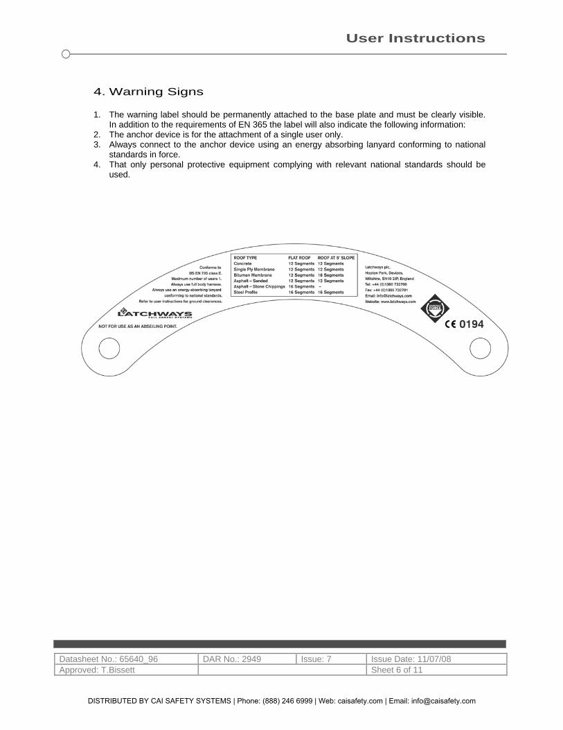
4. Warning Signs
1. The warning label should be permanently attached to the base plate and must be clearly visible.
In addition to the requirements of EN 365 the label will also indicate the following information: 2. The anchor device is for the attachment of a single user only. 3. Always connect to the anchor device using an energy absorbing lanyard conforming to national
standards in force. 4. That only personal protective equipment complying with relevant national standards should be
used.
DISTRIBUTED BY CAI SAFETY SYSTEMS | Phone: (888) 246 6999 | Web: caisafety.com | Email: [email protected]
User Instructions
Datasheet No.: 65640_96 DAR No.: 2949 Issue: 7 Issue Date: 11/07/08 Approved: T.Bissett Sheet 7 of 11
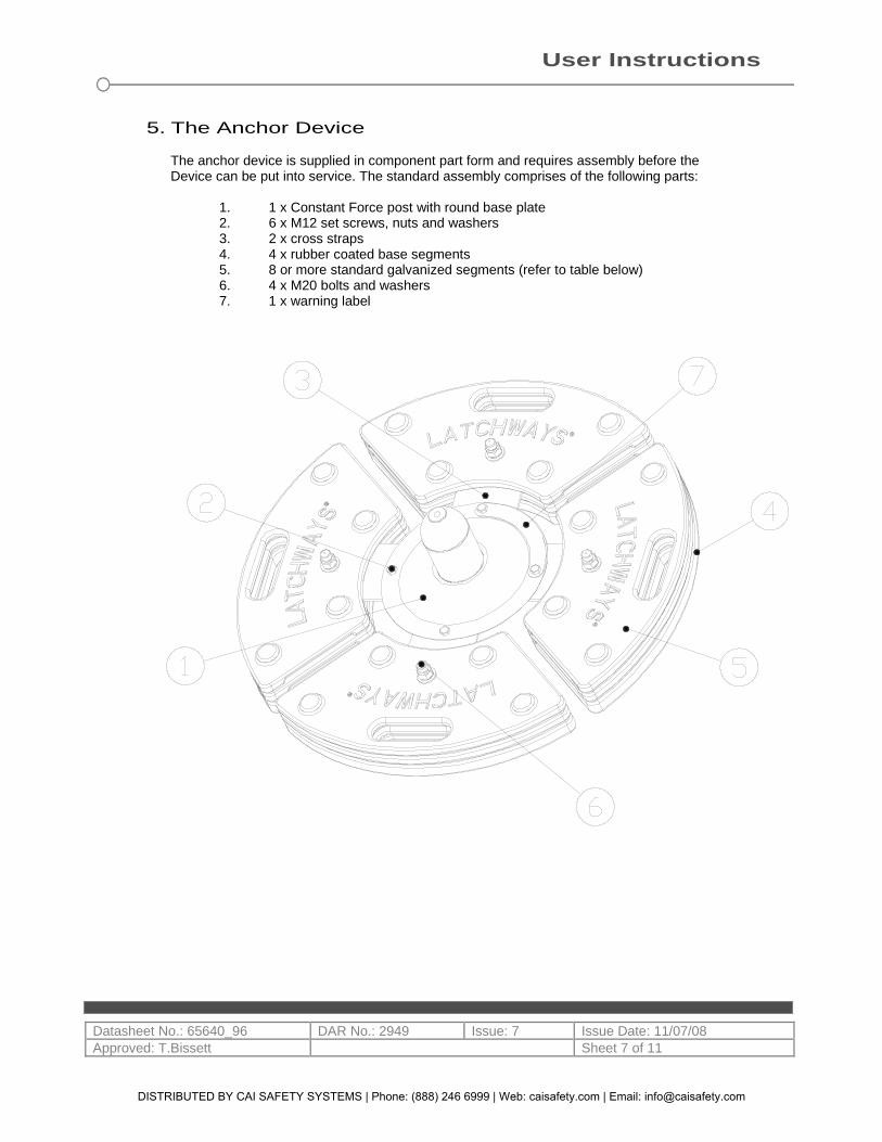
5. The Anchor Device
The anchor device is supplied in component part form and requires assembly before the Device can be put into service. The standard assembly comprises of the following parts: 1. 1 x Constant Force post with round base plate 2. 6 x M12 set screws, nuts and washers 3. 2 x cross straps 4. 4 x rubber coated base segments 5. 8 or more standard galvanized segments (refer to table below) 6. 4 x M20 bolts and washers 7. 1 x warning label
DISTRIBUTED BY CAI SAFETY SYSTEMS | Phone: (888) 246 6999 | Web: caisafety.com | Email: [email protected]
User Instructions
Datasheet No.: 65640_96 DAR No.: 2949 Issue: 7 Issue Date: 11/07/08 Approved: T.Bissett Sheet 8 of 11
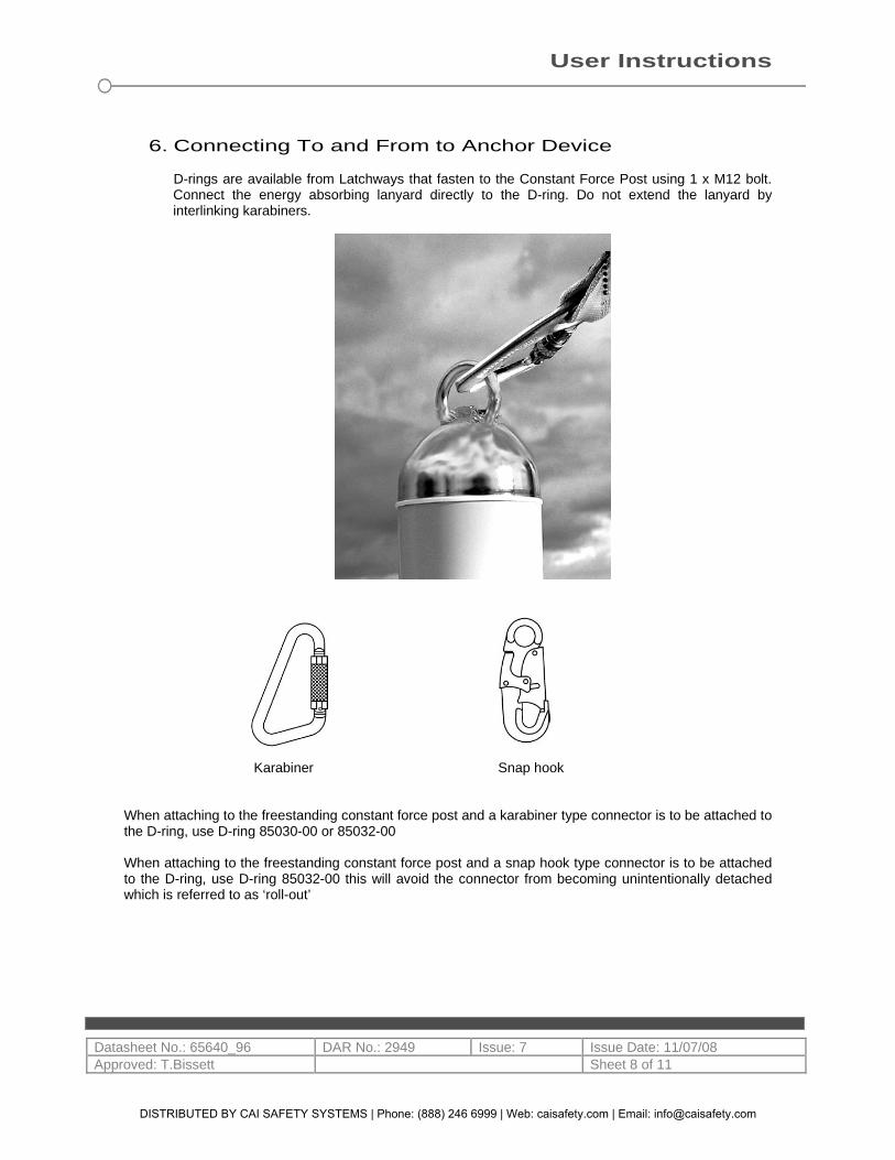
6. Connecting To and From to Anchor Device
D-rings are available from Latchways that fasten to the Constant Force Post using 1 x M12 bolt. Connect the energy absorbing lanyard directly to the D-ring. Do not extend the lanyard by interlinking karabiners.
Karabiner Snap hook
When attaching to the freestanding constant force post and a karabiner type connector is to be attached to the D-ring, use D-ring 85030-00 or 85032-00 When attaching to the freestanding constant force post and a snap hook type connector is to be attached to the D-ring, use D-ring 85032-00 this will avoid the connector from becoming unintentionally detached which is referred to as ‘roll-out’
DISTRIBUTED BY CAI SAFETY SYSTEMS | Phone: (888) 246 6999 | Web: caisafety.com | Email: [email protected]
User Instructions
Datasheet No.: 65640_96 DAR No.: 2949 Issue: 7 Issue Date: 11/07/08 Approved: T.Bissett Sheet 9 of 11
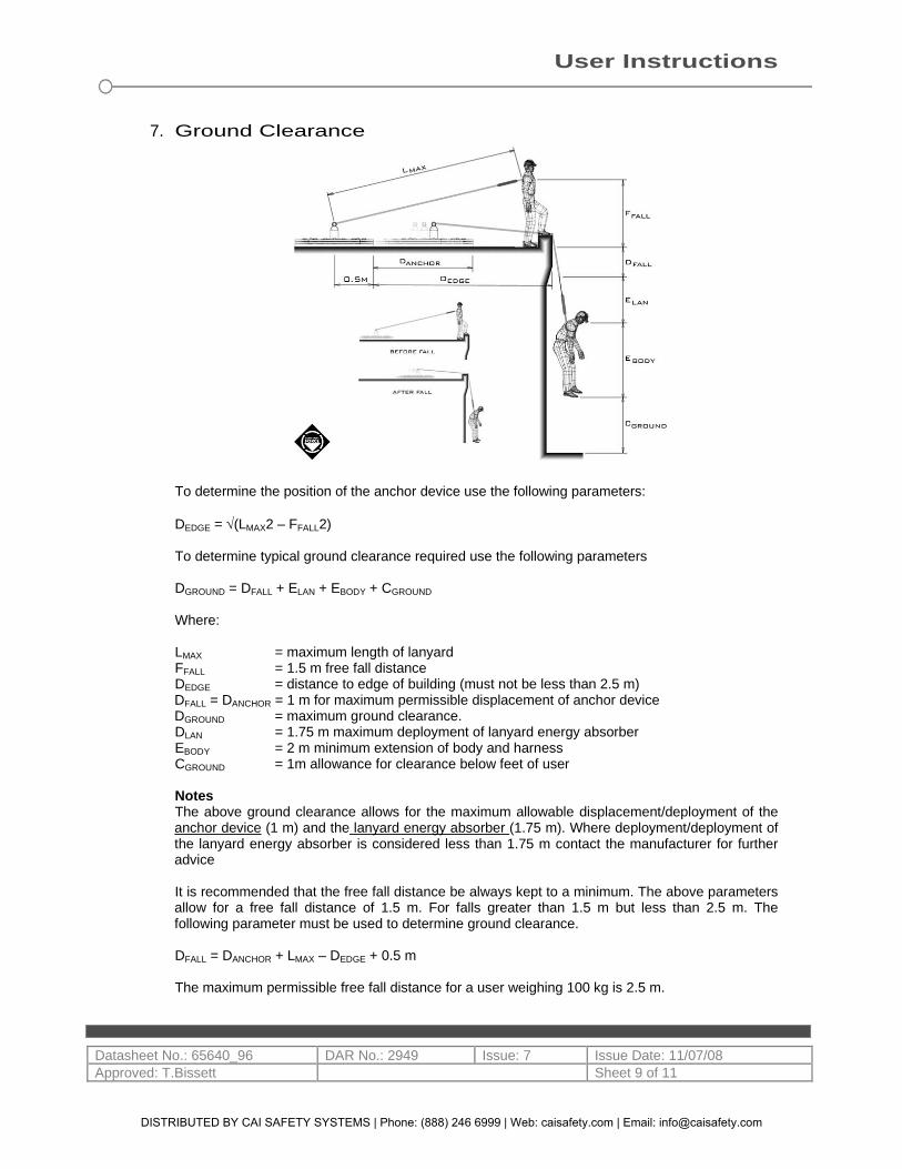
7. Ground Clearance
To determine the position of the anchor device use the following parameters: DEDGE = √(LMAX2 – FFALL2) To determine typical ground clearance required use the following parameters DGROUND = DFALL + ELAN + EBODY + CGROUND Where:
LMAX = maximum length of lanyard FFALL = 1.5 m free fall distance DEDGE = distance to edge of building (must not be less than 2.5 m) DFALL = DANCHOR = 1 m for maximum permissible displacement of anchor device DGROUND = maximum ground clearance. DLAN = 1.75 m maximum deployment of lanyard energy absorber EBODY = 2 m minimum extension of body and harness CGROUND = 1m allowance for clearance below feet of user Notes The above ground clearance allows for the maximum allowable displacement/deployment of the anchor device (1 m) and the lanyard energy absorber (1.75 m). Where deployment/deployment of the lanyard energy absorber is considered less than 1.75 m contact the manufacturer for further advice It is recommended that the free fall distance be always kept to a minimum. The above parameters allow for a free fall distance of 1.5 m. For falls greater than 1.5 m but less than 2.5 m. The following parameter must be used to determine ground clearance. DFALL = DANCHOR + LMAX – DEDGE + 0.5 m The maximum permissible free fall distance for a user weighing 100 kg is 2.5 m.
DISTRIBUTED BY CAI SAFETY SYSTEMS | Phone: (888) 246 6999 | Web: caisafety.com | Email: [email protected]
User Instructions
Datasheet No.: 65640_96 DAR No.: 2949 Issue: 7 Issue Date: 11/07/08 Approved: T.Bissett Sheet 10 of 11
8. Inspection, Maintenance And Storage Inspection before use checks - always inspect the following:
1. No part of the anchor device is less than 2.5 m from any edge including ROOF LIGHTS, hatches
etc. 2. The anchor device is installed so that the rubber coated segments are always in contact with the
roof. 3. The anchor device is assembled using the correct number of segments. 4. The roof surface is an appropriate type as described on the warning label and in these
instructions. 5. The warning label is present and securely attached to the post base plate. 6. All bolts securing the D-ring, constant force post, cross straps and segments are tight. 7. There is no damage to the complete anchor device. 8. There is no damage to the roof area immediately around the anchor device. 9. There is no contamination from oil, grease etc or by growth of algae. 10. Any loose chippings have been removed. 11. The record card has been completed. 12. Signs of corrosion, wear, deformation or other defects to the segments, constant force post
(including the base plate), D-ring.
Annual inspection – the anchor device should be inspected every 12 months by an authorised installer or agent.
1. All of the above checks shall be carried out. 2. Check for deployment of the constant force post. This will be indicated by deployment of the
constant force post by leaning away from the vertical position. For more SEVERE loading the constant force post will be in a horizontal position showing the internal energy absorbing mechanism.
3. Check for signs of modification. The anchor device must not be MODIFIED in any way without written CONSENT from the manufacturer.
4. Record this inspection on the record card as described in section 2.
If the anchor device is damaged, do not attempt repair. Contact your authorised installer or agent for further advice. If there is any doubt about the safe condition of the anchor device, it shall be withdrawn from service. This shall be recorded on the record card. Contact your authorised installer or agent for further advice.
Maintenance
1. Dealing with any defects found during inspection before use and annual inspection. 2. Dismantling and cleaning may be required particularly if algae has formed on the base segments.
Clean the segments using clean water of domestic quality (up to 40°C). If required it may be washed in a domestic grade detergent. All parts should be thoroughly rinsed and dried before re-assembly.
DISTRIBUTED BY CAI SAFETY SYSTEMS | Phone: (888) 246 6999 | Web: caisafety.com | Email: [email protected]

User Instructions
Datasheet No.: 65640_96 DAR No.: 2949 Issue: 7 Issue Date: 11/07/08 Approved: T.Bissett Sheet 11 of 11
Storage
1. The anchor device should be stored away from direct heat, high humidity, sharp edges, corrosives or other foreseeable causes of damage. The equipment should not be subjected to unnecessary stress, pressure or rough handling. Wet equipment should be dried naturally away from direct heat.
2. During storage, all equipment should be kept away from contaminants such as acids, alkalis, oils and grease.
!! CAUTION !! This is a fall protection system. The system must be used in strict conformance with the manufacturer’s instructions. Failure to do so may result in serious injury or death. Do not use or operate this system unless you are properly trained.
DISTRIBUTED BY CAI SAFETY SYSTEMS | Phone: (888) 246 6999 | Web: caisafety.com | Email: [email protected]
Distributed byCAI Safety Systems1609 S Grove Ave, Ste 104Ontario CA 91761Phone: (951) 465-7386Fax: (951) 405-2796Email: [email protected]: https://caisafety.com