Series 11-CRA1 Rotary actuator: Size 30, 50 - SMC ETechcontent2.smcetech.com/pdf/CRA1_Clean.pdf ·...
22
Rotary actuator: Size 30, 50 How to Order Rack & Pinion type Series 11-CRA1 1 5 Size Suction flow rate l/min (ANR) 30 50 Suction flow rate of vacuum suction type (Reference values) Specifications Size Fluid With air cushion Without air cushion With air cushion Max. operating pressure Min. operating pressure Ambient and fluid temperature Cushion Cushion angle Mounting style Adjustable range of rotation time Port size Grease Particle generation grade (Refer to front matter pages 13 to 22 for details.) Allowable kinetic energy (mJ) Air (Non-lube) 0 to 60°C 0.1MPa 1MPa 30 Not available 10 0.2 to 1 s/90° — — M5 x 0.8 50 Without air cushion, With air cushion 50 980 35° 0.2 to 2 s/90° Rc1/8 Fluorine grease Basic style, Flange style Grade 2 11 Vacuum suction type Clean series Nil Auto switch No D With auto switch Shaft type S ∗ Single shaft W Double shaft B Mounting style Basic style L Foot style 30 Size 50 Number of auto switches Nil S 2 pcs. 1 pc. 30 Auto switch A73, J79, F79 50 A54, J59, F59 Cushion Nil C ∗ Without air cushion With air cushion on both ends Standard Rotating angle Option 90° 180° 100° ∗ 190° ∗ 90 180 100 190 11 - C D R A 1 B S 50 - 90 C - A53 ∗ Not available for ø30 ∗ Not available for ø30 ∗ Not available for ø30 ∗ The maximum absorbed energy under proper adjustment of the cushion needle 198
Transcript of Series 11-CRA1 Rotary actuator: Size 30, 50 - SMC ETechcontent2.smcetech.com/pdf/CRA1_Clean.pdf ·...
Rotary actuator: Size 30, 50
How to Order
Rack & Pinion type
Series 11-CRA1
15
Size Suction flow rate l/min (ANR)3050
Suction flow rate of vacuum suction type (Reference values)Specifications
SizeFluid
With air cushionWithout air cushionWith air cushion
Max. operating pressureMin. operating pressureAmbient and fluid temperatureCushion
Cushion angle
Mounting style
Adjustable range of rotation timePort size
Grease
Particle generation grade (Refer to front matter pages 13 to 22 for details.)
Allowable kinetic energy (mJ)
Air (Non-lube)
0 to 60°C0.1MPa1MPa
30
Not available10
0.2 to 1 s/90°
——
M5 x 0.8
50
Without air cushion, With air cushion50
98035°
0.2 to 2 s/90°Rc1/8
Fluorine greaseBasic style, Flange style
Grade 2
11 Vacuum suction type
Clean series
Nil
Auto switchNo
D With auto switch
Shaft typeS∗ Single shaftW Double shaft
B
Mounting styleBasic style
L Foot style
30
Size
50
Number of auto switches
NilS
2 pcs.1 pc.
30
Auto switchA73, J79, F79
50 A54, J59, F59
Cushion
NilC ∗
Without air cushion
With air cushion on both ends
Standard
Rotating angle
Option
90°180°100°∗
190°∗
90180100190
11 - C D R A 1 B S 50 - 90 C - A53
∗ Not available for ø30
∗ Not available for ø30
∗ Not available for ø30
∗ The maximum absorbed energy under proper adjustment of the cushion needle
198
Air
cylin
der
Rot
ary
actu
ator
Air
grip
per
Dire
ctio
nal c
ontr
olva
lve
Fitt
ings
& T
ubin
gP
ress
ure
switc
hC
lean
gas
filte
rF
low
con
trol
equi
pmen
tF
ilter
, Pre
ssur
eco
ntro
l equ
ipm
ent
Air
prep
arat
ion
equi
pmen
t
Auto switch specifications (Refer to Best Pneumatics catalog for further information on auto switches.)
TypeReed switch
2-wire3-wire
Solid stateswitch
Auto switch model
D-A73D-J79D-F79
Load voltage
24 VDC/100 VAC24 VDC (10 to 28 VDC)
28 VDC or less
5 to 40 mA, 5 to 20 mA5 to 150 mA
150 mA or less
Load current range Indicator lightYesYesYes
Applicable load
24 VDC relay, PLC
Rotary actuator 11-CRA1
30
Reed switch2-wire3-wire
Solid stateswitch
D-A54D-J59D-F59
24 VDC/100 VAC/200 VAC24 VDC (10 to 28 VDC)
28 VDC or less
5 to 50 mA, 5 to 25 mA, 5 to 12.5 mA5 to 150 mA
150 mA or less
YesYesYes
Relay, PLC50 24 VDC relay, PLC
Relay, PLC
Relay, PLC, IC circuit
Relay, PLC, IC circuit
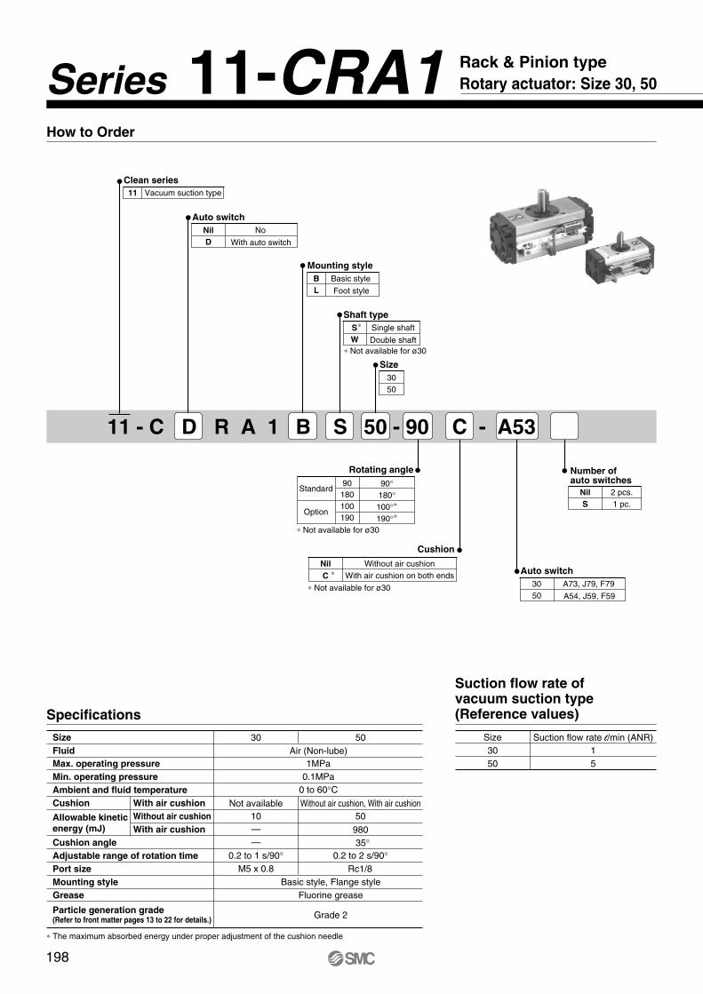
Proper auto switch mounting position
11-CDRA1W30-90/18011-CDRA150-90/180
A (mm)9 (19)9 (26)
Operating range95°65°
Hysteresis range20°20°
Model
∗ The dimensions inside ( ) are for 180°.∗∗ Up to 2 auto switches can be mounted per actuator.
Size 30 Size 50
Auto switch
A A
Auto switch
A A
PLC: Programmable Logic ControllerRefer to page 212 for a list of applicable auto switches.
199
11-CRA1Rotary actuator
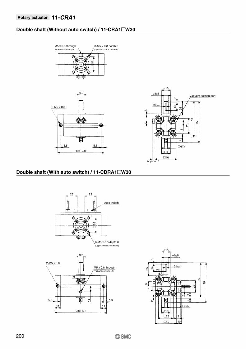
Double shaft (Without auto switch) / 11-CRA1W30
Double shaft (With auto switch) / 11-CDRA1W30
M5 x 0.8 through(Vacuum suction port)
8-M5 x 0.8 depth 6(Opposite side 4 locations)
2
89.2
2-M5 x 0.8
5.5 5.5
84(103)
ø16
ø8g6
3-0.0250
29
314
25
65
75
28
112
40
ø16
Approx. 5
Vacuum suction port
9.2
2-M5 x 0.8
11
5.5
98(117)
ø16
ø8g6
3-0.0250
2
9
31425
65
75
2
40
ø16
23 23
Auto switch
8-M5 x 0.8 depth 6(Opposite side 4 locations)
2
8
M5 x 0.8 through(Vacuum suction port)
9
5.5
11
11
28 7
10
8
8 9
22
5
6-0.20
6-0.20
200
Air
cylin
der
Rot
ary
actu
ator
Air
grip
per
Dire
ctio
nal c
ontr
olva
lve
Fitt
ings
& T
ubin
gP
ress
ure
switc
hC
lean
gas
filte
rF
low
con
trol
equi
pmen
tF
ilter
, Pre
ssur
eco
ntro
l equ
ipm
ent
Air
prep
arat
ion
equi
pmen
t
Rotary actuator 11-CRA1
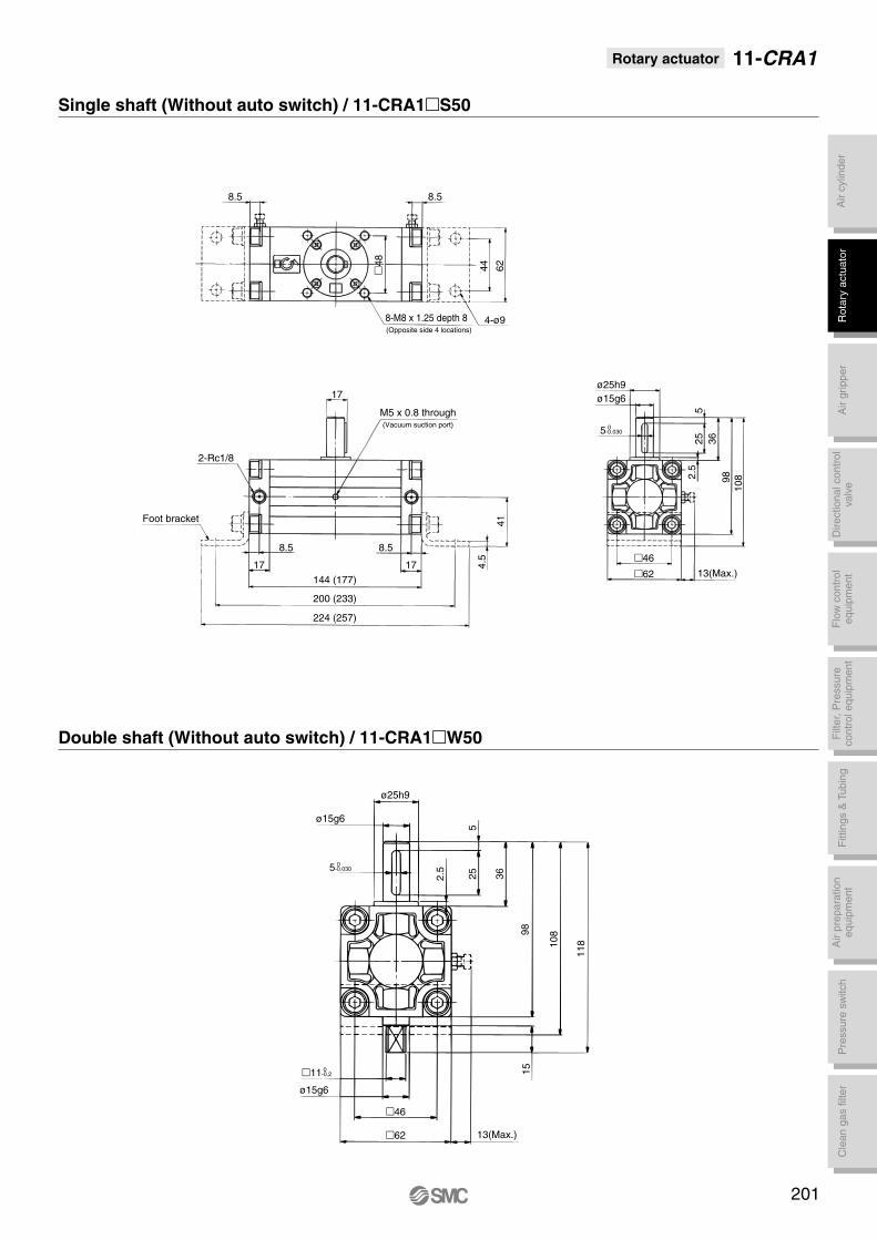
Single shaft (Without auto switch) / 11-CRA1S50
Double shaft (Without auto switch) / 11-CRA1W50
8-M8 x 1.25 depth 8(Opposite side 4 locations)
48
8.5
2-Rc1/8
8.5 8.5
4-ø9
5-0.0300
41
525
46
ø15g6
ø25h9
9815
13(Max.)
8.5
44 62
Foot bracket
17
144 (177)
224 (257)
200 (233)
17 4.5
ø25h9ø15g6
36
2.5
9810
8
62 13(Max.)
M5 x 0.8 through(Vacuum suction port)
17
ø15g6
5-0.0300
46
62
108
118
36252.5
5
11-0.20
201
11-CRA1Rotary actuator
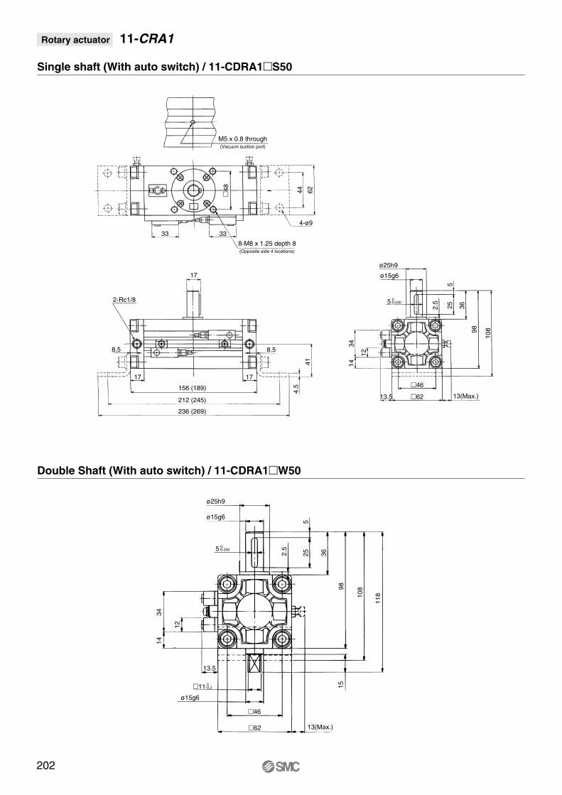
Single shaft (With auto switch) / 11-CDRA1S50
Double Shaft (With auto switch) / 11-CDRA1W50
8-M8 x 1.25 depth 8(Opposite side 4 locations)
48
2-Rc1/8
8.5
4-ø9
5-0.0300
41
525
46
ø15g6
ø25h9
98
34
13(Max.)
44 62
17
156 (189)
236 (269)
212 (245)
4.5
ø25h9
ø15g6
362.5
98
108
6213.5 13(Max.)
M5 x 0.8 through(Vacuum suction port)
33
ø15g6
5-0.0300
46
62
108
118
36252.5
5
33
8.5
17
14
12
13.5
15
17
12
3414
202
11-0.20

Air
cylin
der
Rot
ary
actu
ator
Air
grip
per
Dire
ctio
nal c
ontr
olva
lve
Fitt
ings
& T
ubin
gP
ress
ure
switc
hC
lean
gas
filte
rF
low
con
trol
equi
pmen
tF
ilter
, Pre
ssur
eco
ntro
l equ
ipm
ent
Air
prep
arat
ion
equi
pmen
t
Rotation range of keyway / Switch mounting position
11-CDRA1W30 11-CDRA150
Proper auto switch mounting position at rotation end11-CDRA1W30 11-CDRA150 to 100
Auto switch
Direction indicatinglabel
Ang
le a
djus
tmen
t ra
nge
±3°
Angle adjustmentrange ±3°
Stopper screw
Ang
le a
djus
tmen
t ra
nge
±3°
Ang
le a
djus
tmen
t ra
nge
±3°
A port
Rotation range of keyway 180°
Rotation range
ofke
yway
90°
Rotation range of keyway 190° 0+4°
Rotation range of keyway 180° 0+4°
Rotation range ofke
yway
90°
0 +4°
Rotation range
ofke
yway
100°
0+4°
Auto switch
Direction indicating label
A portB portB port
∗ If air pressure is applied from the A side of the direction indicating label, the shaft rotates clockwise. If air pressure is applied from the B side, the shaft rotates counterclockwise.
Model A (mm)
9 (19)
9 (26)
11 (30)
15 (37)
27 (60)
Operating angle θ m95°65°60°45°35°
Hysteresis angle
20°20°10° 7° 5°
11-CDRA1W 30-90
11-CDRA150-90
11-CDRA163-90
11-CDRA180-90
11-CDRA1100-90
∗ The dimensions inside ( ) are for 180. ∗∗ Up to 2 auto switches can be mounted per actuator.
The dimensions in the table are the values that represent the most sensitive positions of the auto switches.
Thus, they are not the dimensions that represent the mounting position at the time of shipment. Please consult with SMC concerning the angles for the auto switches other than the models D-A73 and D-A53.
Operating angle θ m: Converts the operating range (Lm) of the auto switch into the rotation angle.Angle of hysteresis: The hysteresis of the auto switch is converted to degrees.
Note 1)
203
Rotary actuator 11-CRA1

Rotary ActuatorsPrecautions 1Be sure to read this before handling.
Design/Selection
Warning1. Confirm the specifications.
Products represented in this catalog are designed only for use in compressed air systems (including vacuum).Do not operate at pressures or temperatures, etc., beyond the range of specifications, as this can cause damage or malfunc-tion. (Refer to the specifications.)Please contact SMC when using a fluid other than com-pressed air (including vacuum).We do not guarantee against any damage if the product is used outside of the specification range.
2. If the operation involves load fluctuations, ascending/descending movements, or chang-es in frictional resistance, make sure to pro-vide safety measures. Operating speed will increase, and bodily injury may occur, or damage to the machinery itself may occur.
3. If there is a chance that the product will pose a hazard to humans, install a protective cover.If the moving portion of the product will pose a hazard to hu-mans or will damage machinery or equipment, provide a con-struction that prevents direct contact with those areas.
4. Be certain that the secured portions will not loosen.Be certain to adopt a reliable connecting method if the rotary actuator is used very frequently or if it is used in a location that is exposed to a large amount of vibration.
5. There may be cases in which a speed reduc-tion circuit or a shock absorber is required.If the driven object moves at high speeds or is heavy, it will be unfeasible for only the rotary actuator’s cushion to absorb the shock. Therefore, provide a speed-reduction circuit to reduce the rotary actuator’s speed before the thrust is applied to the cushion, or an external shock absorber to dampen the shock. If these countermeasures are taken, make sure to take the ri-gidity of the machinery and equipment into consideration.
6. Consider the possibility of a reduction in the circuit air pressure caused by a power failure.When an actuator is used as clamping mechanism, there is a danger of workpiece dropping if there is a decrease in clamp-ing force, due to a drop in circuit pressure caused by a power failure. Therefore, safety equipment should be installed to pre-vent damage to machinery/equipment and bodily injury.
7. Consider the possibility of power source re-lated malfunctions that could occur.For the machinery and equipment that rely on power sources such as compressed air, electricity, or hydraulic pressure, adopt a countermeasure to prevent the equipment from causing a hazard to humans or damage to the machinery and equipment in the event of malfunction.
8. If a speed controller is provided in the exhaust restrictor, implement a safety design taking the residual pressure into consideration.If air pressure is applied to the air supply side without residual pressure in the exhaust side, the rotary actuator will operate at abnormally high speed, which could pose a hazard to humans and can damage the machinery and equipment.
9. Consider the behavior of the rotary actuator in the event of an emergency stop.Devise a safe system so that if a person engages the emergen-cy stop, or if a safety device is tripped during a system malfunc-tion such as a power failure, the movement of the rotary actua-tor will not cause a hazard to humans or damage the equipment.
10. Consider the action of the rotary actuator when restarting after an emergency stop.Devise a safe design so that the restarting of the rotary actua-tor will not pose a hazard to humans or damage the equip-ment. Install manually controlled equipment for safety when the actuator has to be reset to the starting position.
11. Do not use the product as a shock absorber.If an abnormal pressure or air leakage occurs, the rotary actuator’s speed reduction capability could become severely effected, which could pose a hazard to humans and damage the machinery and equipment.
12. Select a speed within the product’s allow-able energy value.If the product’s kinetic energy of the load exceeds the allow-able value, it could damage the product, and cause a hazard to humans and damage the machinery and equipment.
13. Provide a shock absorber if the kinetic ener-gy that is applied to the product exceeds the allowable value.If the product’s kinetic energy exceeds the allowable value, it could damage the product, and cause a hazard to humans and damage the machinery or equipment.
14. Do not stop or hold the product at midpoint by keeping air pressure in the product.For a product lacking an external stopping mechanism, if the directional control valve is closed to keep the air pressure in the product, in an attempt to stop the product at midpoint, it might not be possible to maintain that stopped position due to an air leakage. As a result, it could pose a hazard to humans and cause damage to machinery and/or equipment.
15. Give consideration to the decline in strength caused by changes of the shaft type.Some shaft types, such as simple specials, may have shapes and dimensions that result in decreased strength when com-pared with standard models. Consider this carefully when using.
16. Do not use two or more rotary actuators with the aim of synchronized movement.One of the actuators may bear the load of operation, making synchronized movement impossible, and possibly leading to deformation of the equipment.
17. Do not use in a location where adverse ef-fect could be occurred by the oozing of the lubricant to the exterior.The lubricant coating the interior of the product may leak to the outside of the product from the portion of the connection of the rotary shaft, body cover, etc.
18. Do not disassemble the product or make any modifications, including additional machining.It may cause human injury and/or an accident.
19. Refer to the Auto Switches Precautions (pages 13 to 16) for using with an auto switch.
23
Design/Selection
CautionMounting
1. Do not use below the speed adjustment range specified for the product.If the product is used below the specified speed adjustment range, it could cause the product to stick, slip, or the move-ment to stop.
2. Do not apply an external torque to the prod-uct that exceeds the rated output.If an external force that exceeds the product’s rated output is applied to the product, it could damage the product.
3. The holding torque of the rotating end of the double piston type.If the internal piston of a double piston product comes in contact with the angle adjustment screen or the cover and stops, the holding torque at the rotating end is one half of the actual output.
4. If it is necessary to provide repeatability of the rotation angle, directly stop the load externally.Even with a product that is equipped with an angle adjuster, there are times in which the initial rotation angle could change.
5. Do not use under hydraulic pressure.The product will be damaged if it is used by applying hydraulic pressure.
6. There is a possibility of backlash being gen-erated when stopping the double piston style in the middle with a valve of the closed center type.
7. For the vane type product, if it is necessary to ensure a rotation angle, make sure to use a minimum pressure of 0.3 MPa.
8. Do not use the made-to-order -XC30 at low speeds. Although fluorine grease is used, it is not designed for low-speed applications.For information on fluorine grease, refer to the Material Safety Data Sheet (MSDS).
9. Do not use in places where there are many temperature fluctuations. When using in lower temperature applications, use caution so that frost does not occur inside the cylin-der or the piston rod.Operation may be unstable.
10. Adjust the speed control in the environment in which it will be used in.Speed adjustment may be changed if the environment is different.
2. Ensure sufficient space for maintenance activities.When installing the products, allow access for maintenance.
3. Tighten threads with the proper tightening torque.When installing the products, follow the listed torque specifications.
4. Before adjusting the angle by supplying air pressure, take appropriate measures to prevent the equipment from rotating unnecessarily.When an adjustment is performed under air pressure, the equipment could rotate and fall during the adjustment, depending on the mounted placement of the equipment. As a result, it could pose a hazard to humans and damage the machinery and equipment.
5. Do not loosen the angle adjustment screw beyond the allowable adjustment range.The angle adjustment screw could fall out if it is loosened beyond its allowable adjustment range and cause a hazard to humans and damage to machinery and equipment.
6. Do not place a magnetic object near the product.The auto switch is a magnetic sensing type. If a magnetic object is placed close to it, the rotary actuator could operate suddenly, which could pose a hazard to humans and damage the machinery and equipment.
7. Do not perform additional machining to the product.Additional machining to the product can result in insufficient strength and cause damage to the product. This can lead to pos-sible human injury and damage to the surrounding equipment.
8. Do not enlarge the fixed throttle by modify-ing the pipe connectors.If the hole diameter is enlarged, the product’s rotation speed will increase, causing the shock force to increase and damage to the product. As a result, it could pose a hazard to humans and damage the machinery and equipment.
9. If shaft couplings are used, use those with angular freedom.If shaft couplings that lack angular freedom are used, they could scrape due to eccentricity, leading to equipment malfunction and product damage. As a result, it could pose a hazard to humans and damage the machinery and equipment.
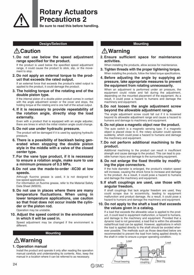
10. Do not apply to the shaft a load that exceeds the values given in a catalog.If a load that exceeds the allowable value is applied to the prod-uct, it could lead to equipment malfunction, a hazard to humans, and damage to the machinery and equipment. Provided that a dynamic load is not generated, a load that is within the allowable radial/thrust load can be applied. However, applications in which the load is applied directly to the shaft should be avoided wher-ever possible. The methods such as those described below are recommended to prevent the load from being applied directly to the shaft in order to ensure a proper operating condition.
Mounting
Warning1. Operation manual
Install the product and operate it only after reading the operation manual carefully and understanding its contents. Also, keep the manual in a location where it can be referred to as necessary.
Load
Thrust bearingFlexiblecoupling
Load
Bearing
Warning
Rotary ActuatorsPrecautions 2Be sure to read this before handling.
24
Mounting
12. Do not use springs, etc., to add force in the rotational movement direction.When rotational force from an external spring, etc., acts and generates negative pressure on the product’s interior, break-age of the internal seal or acceleration of abrasion may occur.
Piping
Caution1. Refer to the Fittings and Tubing Precautions
(pages 38 to 41) for handling one-touch fit-tings.
2. Preparation before pipingBefore piping is connected, it should be thoroughly blown out with air (flushing) or washed to remove chips, cutting oil and other debris from inside the pipe.
3. Wrapping of pipe tapeWhen screwing piping or fittings into ports, ensure that chips from the pipe threads or sealing material do not enter the piping. Also, if pipe tape is used, leave 1.5 to 2 thread ridges exposed at the end of the threads.
Windingdirection
Pipe tapeExpose approx. 2 threads
Caution1. Observe the specified torque to secure the
block of the angle adjustment unit.If it is secured with a torque that is lower than the specified torque, the block could become loosened during use, causing the angle to exceed the set angle.
2. Do not use organic solvent to wipe the area of the name plate that shows the model.It will erase what is indicated on the name plate.
3. Do not hit the rotating shaft by securing the body or hit the body by securing the rotating shaft.These actions could cause the shaft to bend or damage the bearing. When a load must be coupled to the rotating shaft, secure the rotating shaft.
4. Do not place your foot directly on the shaft or on the equipment that is coupled to the shaft.Placing one’s weight directly onto the rotating shaft could cause the rotating shaft or the bearing to become damaged.
5. If a product is equipped with an angle ad-justment function, use it within the specified adjustment range.If the product is used outside the specified adjustment range, it could lead to equipment malfunction or product damage. Refer to the product specifications for details on the adjust-ment range of the products.
Stopper
Rotary actuator
θ
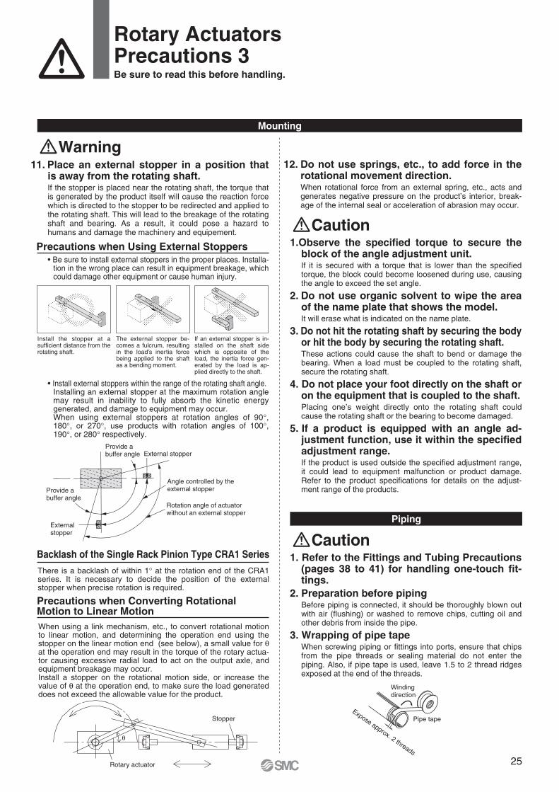
When using a link mechanism, etc., to convert rotational motion to linear motion, and determining the operation end using the stopper on the linear motion end (see below), a small value for θ at the operation end may result in the torque of the rotary actua-tor causing excessive radial load to act on the output axle, and equipment breakage may occur.Install a stopper on the rotational motion side, or increase the value of θ at the operation end, to make sure the load generated does not exceed the allowable value for the product.
Precautions when Converting Rotational Motion to Linear Motion
There is a backlash of within 1° at the rotation end of the CRA1 series. It is necessary to decide the position of the external stopper when precise rotation is required.
Backlash of the Single Rack Pinion Type CRA1 Series
The external stopper be-comes a fulcrum, resulting in the load’s inertia force being applied to the shaft as a bending moment.
Install the stopper at a sufficient distance from the rotating shaft.
If an external stopper is in-stalled on the shaft side which is opposite of the load, the inertia force gen-erated by the load is ap-plied directly to the shaft.
External stopper
External stopper
Provide a buffer angle
Angle controlled by the external stopper
Rotation angle of actuator without an external stopper
Provide a buffer angle
Rotary ActuatorsPrecautions 3Be sure to read this before handling.
11. Place an external stopper in a position that is away from the rotating shaft.If the stopper is placed near the rotating shaft, the torque that is generated by the product itself will cause the reaction force which is directed to the stopper to be redirected and applied to the rotating shaft. This will lead to the breakage of the rotating shaft and bearing. As a result, it could pose a hazard to humans and damage the machinery and equipement.
Precautions when Using External Stoppers• Be sure to install external stoppers in the proper places. Installa-
tion in the wrong place can result in equipment breakage, which could damage other equipment or cause human injury.
• Install external stoppers within the range of the rotating shaft angle.Installing an external stopper at the maximum rotation angle may result in inability to fully absorb the kinetic energy generated, and damage to equipment may occur.When using external stoppers at rotation angles of 90°, 180°, or 270°, use products with rotation angles of 100°, 190°, or 280° respectively.
Warning
25
Speed and Cushion Adjustment
Warning1. To make a speed adjustment, gradually ad-
just starting from the low speed end.If the speed adjustment is performed from the high speed end, it could damage the product. As a result, it could pose a hazard to humans and damage the machinery and equipment.
2. The cushion needle is not adjusted at the time of shipment. Therefore, an adjustment must be made in accordance with the operating speed and the moment of inertia of the load.The absorption of kinetic energy by the bumper is regulated by the adjustment of the needle. An improper adjustment could lead to damage of the equipment and the product. As a result, it could pose a hazard to humans and damage the machinery and equipment.
3. Do not operate with the cushion needle in a fully closed condition.This could tear the seal, which could pose a hazard to humans and damage the machinery and equipment.
4. Do not apply an excessive force to loosen the cushion needle.The needle itself is provided with a pull stop. However, the pullstop could be damaged if the needle is loosened through the application of excessive force. As a result, it could pose a hazard to humans and damage the machinery and equipment.
5. For products with shock absorbers, when the shock absorber stops motion before reaching the stroke end using a stopper mechanism with the objective of shortening takt time, be sure the shock absorber is stopped in a position where it has adequately absorbed the kinetic energy.Failure to do so can result in damage to equipment.
Air Supply
Warning1. Type of fluids
Please consult with SMC when using the product in applications other than compressed air.
2. When there is a large amount of drainage.Compressed air containing a large amount of drainage can cause malfunction of pneumatic equipment. An air dryer or water separator should be installed upstream from filters.
3. Drain flushingIf condensation in the drain bowl is not emptied on a regular basis, the bowl will overflow and allow the condensation to enter the compressed air lines. It causes malfunction of pneumatic equipment.If the drain bowl is difficult to check and remove, installation of a drain bowl with an auto drain option is recommended.
For compressed air quality, refer to SMC’s Best Pneumatics catalog.
4. Use clean air.Do not use compressed air that contains chemicals, synthetic oils including organic solvents, salt or corrosive gases, etc., as it can cause damage or malfunction.
Caution1. When extremely dry air is used as the fluid,
degradation of the lubrication properties inside the equipment may occur, resulting in reduced reliability (or reduced service life) of the equipment. Please consult with SMC.
2. Install an air filter.Install an air filter upstream near the valve. Select an air filter with a filtration size of 5 µm or smaller.
3. Take measures to ensure air quality, such as by installing an aftercooler, air dryer, or water separator.Compressed air that contains a large amount of drainage can cause malfunction of pneumatic equipment such as rotary actuators. Therefore, take appropriate measures to ensure air quality, such as by providing an aftercooler, air dryer, or water separator.
4. Ensure that the fluid and ambient tempera-ture are within the specified range.If the fluid temperature is 5°C or less, the moisture in the circuit could freeze, causing damage to the seals and equip-ment malfunction. Therefore, take appropriate measures to prevent freezing.
For compressed air quality, refer to SMC’s Best Pneumatics catalog.
Rotary ActuatorsPrecautions 4Be sure to read this before handling.
Lubrication
Warning1. This product should be used without lubrica-
tion. If it is lubricated, it could lead to stick-ing or slipping.
26

Maintenance
Warning1. Perform maintenance inspection according
to the procedures indicated in the operation manual.If handled improperly, malfunction and damage of machinery or equipment may occur.
2. Maintenance workIf handled improperly, compressed air can be dangerous. Assembly, handling, repair and element replacement of pneumatic systems should be performed by a knowledgeable and experienced person.
3. Drain flushingRemove drainage from air filters regularly.
4. Removal of equipment, and supply/exhaust of compressed airWhen components are removed, first confirm that measures are in place to prevent workpieces from dropping, run-away equipment, etc. Then, cut off the supply pressure and electric power, and exhaust all compressed air from the system using the residual pressure release function.When machinery is restarted, proceed with caution after confirming that appropriate measures are in place to prevent cylinders from sudden movement.
Caution1. For lubrication, use the designated grease
for each specific product.The use of a non-designated lubricant could damage the seals.
Rotary ActuatorsPrecautions 5Be sure to read this before handling.
Operating Environment
1. Do not use in an atmosphere having corro-sive gases, chemicals, sea water, water, water steam, or where there is direct contact with any of these.Refer to the construction for information on the rotary actuators material.
2.Do not expose the product to direct sunlight for an extended period of time.
3. Do not use in a place subject to heavy vibration and/or shock.
4.Do not mount the product in locations where it is exposed to radiant heat.
5.Do not use in dusty locations or where water or oil, etc., splash on the equipment.
Warning
27
Design
Warning1. Do not use the product near flames, or in
equipment or machinery that exceeds an ambient temperatures of 60°C.There is a danger of causing a fire because the air-hydro type uses a flammable hydraulic fluid.Refer to the Material Safety Data Sheet (MSDS) of the hydraulic fluid when supplying the fluid.
2. Do not use the product in a clean room.
Caution1. Do not use in an environment, equipment, or
machine that is not compatible with oil mist.The air-hydro type generates an oil mist during operation which may affect the environment.
2. Be certain to install an exhaust cleaner on the directional control valve for the air-hydro type.A very small amount of hydraulic fluid is discharged from the exhaust port of a directional control valve, which may contami-nate the surrounding area.
3. Install the air-hydro type in locations where it can be serviced easily.Since the air-hydro type requires maintenance, such as refilling of hydraulic fluid and bleeding of air, ensure sufficient space for these activities.
Selection
Caution1. Select an air-hydro type in combination with
an air-hydro unit.Since good operation of an air-hydro type depends on its combination with an air-hydro unit, carefully select an appro-priate air-hydro unit.
Piping
Warning1. For air-hydro type piping, use self-aligning
fittings.Do not use one-touch fittings in the piping for an air-hydro type, because oil leakage may occur.
2. For air-hydro type piping, use hard nylon tubing or copper piping.As in the case of hydraulic circuits, surge pressures greater than the operating pressure may occur in an air-hydro type piping, making it necessary to use safer piping materials.
Lubrication
Warning1. Completely discharge the compressed air in
the system before filling the air-hydro unit with hydraulic oil.When supplying hydraulic fluid to the air-hydro unit, first confirm that safety measures are implemented to prevent dropping of objects and the release of clamped objects, etc. Then, shut off the air supply and the equipment’s electric power and exhaust the compressed air in the system.If the air-hydro unit’s supply port is opened with compressed air still remaining in the system, there is a danger of hydraulic fluid being blown out.Refer to the Material Safety Data Sheet (MSDS) of the hydraulic fluid when supplying the fluid.
2. Use petroleum hydraulic fluid which can be used as turbine oil.If non-flammable hydraulic fluid is used, it may cause problems.Suitable viscosity is in the range of approximately 40 to 100 mm2/s in operating temperature.The suitable operating temperature for ISO VG32 is the range of 15 to 35°C. If the operating temperature range is beyond ISO VG32, select ISO VG46 (suitable for 25 to 45°C range).
Note) Refer to SMC’s website for details about each manufactur-er’ s brand name of class 1 turbine oil (no additive) ISO VG32. Additionally, please contact SMC for details about class 2 turbine oil (with additives) ISO VG32.
For Air-hydro TypePlease read this page along with the Rotary Actuators Precautions.
Rotary ActuatorsPrecautions 6Be sure to read this before handling.
Caution1. Bleed air from the air-hydro type on a regu-
lar basis.Since air may accumulate inside the air-hydro type, bleed air from it, for example before starting work. Bleed air from a bleeder valve provided on the air-hydro type or the piping.
2. Verify the oil level of the air-hydro system on a regular basis.Since a very small amount of hydraulic fluid is discharged from the air-hydro type and the air-hydro unit circuit, the fluid will gradually decrease. Therefore, check the fluid regularly and refill as necessary.The oil level can be checked with a level gauge in the air-hydro converter.
Maintenance
28
Cylinders or actuators include cylinders, air grippers, rotary actuators, and electrical actuators/cylinders.
Design/Selection
Warning1. Confirm the specifications.
If the product is used with excess load applied or beyond the specification range, this may cause the product to break or malfunction. We do not guarantee against any damage if the product is used outside of the specification range.
2. Cautions for use in an interlock circuitWhen an auto switch is used for an interlock signal requiring high reliability, devise a double interlock system to avoid trouble by providing a mechanical protection function, or by also using another switch (sensor) together with the auto switch. Also, perform periodic maintenance and confirm proper operation.
3. Do not attempt to disassemble, modify (including exchanging the printed circuit boards), or repair the product.An injury or failure can result.
Caution4. Do not mount the cylinder or actuator with
the auto switch on a footing. If work personnel gets on or puts the work personnel’s foot on the footing accidentally, an excessive load is applied to the cylinder or actuator, causing the cylinder or actuator to break.
5. Design the circuit so that any back-flow cur-rent does not flow in if a short-circuit trouble occurs or forced operation is performed to check the operation.If a back-flow current occurs, this may cause the switch to malfunction or break.
6. When multiple auto switches are required.“n” indicates the number of auto switches which can be physi-cally mounted on the cylinders/actuators. Detection intervals depends on the auto switch mounting structure and set position, therefore some required interval and set positions may not be available.
7. Limitations on detectable positionThere are positions or surfaces (bottom surface of the foot bracket, etc.) where the auto switch cannot be mounted due to the physical interference depending on the cylinder or actu-ator mounting status or mounting bracket. Select an appropri-ate auto switch setting position where the auto switch does not interfere with the cylinder or actuator mounting bracket (trunnion or reinforcing ring) after checking it sufficiently.
Auto SwitchesPrecautions 1Be sure to read this before handling.
Caution1. Pay attention to the length of time that a switch
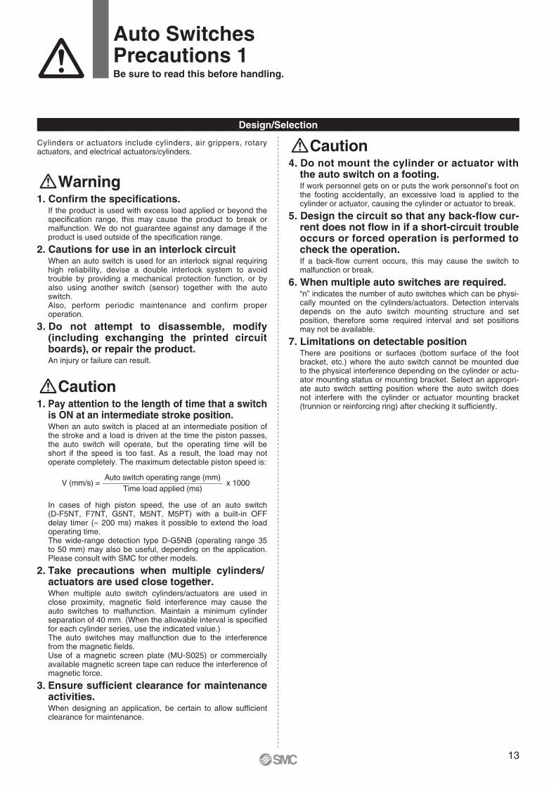
is ON at an intermediate stroke position.When an auto switch is placed at an intermediate position of the stroke and a load is driven at the time the piston passes, the auto switch will operate, but the operating time will be short if the speed is too fast. As a result, the load may not operate completely. The maximum detectable piston speed is:
In cases of high piston speed, the use of an auto switch (D-F5NT, F7NT, G5NT, M5NT, M5PT) with a built-in OFF delay timer (≈ 200 ms) makes it possible to extend the load operating time.The wide-range detection type D-G5NB (operating range 35 to 50 mm) may also be useful, depending on the application. Please consult with SMC for other models.
2. Take precautions when multiple cylinders/actuators are used close together.When multiple auto switch cylinders/actuators are used in close proximity, magnetic field interference may cause the auto switches to malfunction. Maintain a minimum cylinder separation of 40 mm. (When the allowable interval is specified for each cylinder series, use the indicated value.)The auto switches may malfunction due to the interference from the magnetic fields.Use of a magnetic screen plate (MU-S025) or commercially available magnetic screen tape can reduce the interference of magnetic force.
3. Ensure sufficient clearance for maintenance activities.When designing an application, be certain to allow sufficient clearance for maintenance.
Auto switch operating range (mm)Time load applied (ms)
x 1000V (mm/s) =
13

1.Do not drop or bump.Do not drop, bump, or apply an excessive impact (300m/s2 or more for reed auto switches, 1000m/s2 or more for solid state auto switches) while handing the auto switch. It may cause the auto switch to break or malfunction.
2. Observe the proper tightening torque for mounting an auto switch.When an auto switch is tightened beyond the range of tighten-ing torque, auto switch mounting screws, auto switch mounting brackets or auto switch may be damaged. On the other hand, tightening below the range of tightening torque may allow the auto switch to slip out of position.
3. Do not carry a cylinder by the auto switch lead wires.This may cause disconnection of the lead wire or the internal element to break.
4. Do not use screws other than the set screws installed on the auto switch body to secure the auto switch.If using other screws, auto switch may be damaged.
5. Mount an auto switch at the center of the operating range. In the case of 2-color display auto switch, mount it at the cen-ter of the green LED illuminating range.Adjust the mounting position of the auto switch so that the pis-ton stops at the center of the operating range. (The mounting position shown in the catalog indicates the optimum position at stroke end.) If mounted at the end of the operating range (around the bor-derline of ON and OFF), operation will be unstable depending on the operating environment. Also there are some cylinders or actuators with individual setting methods for auto switches. If so, mount it in accordance with the indicated method.
6. Check the actual actuation status and adjust the auto switch mounting position. According to the installation environment, the cylinder or ac-tuator may not operate even at its proper mounting position. Even when setting at a midpoint of the stroke, check the ac-tuation status and make the adjustment in the same manner.
1.Confirm proper insulation of wiring.If there is any improper insulation (mixed contact with other circuit, grounding fault, or improper insulation between terminals, etc.) in the wiring, an over-current flows in, causing the auto switch to break.
2. Wire separately from power lines or high voltage lines, avoiding parallel wiring or wir-ing in the same conduit with these lines.If an inrush current is generated, the noise may cause the au-to switch to malfunction.
3. Avoid repeatedly bending or stretching lead wires.Broken lead wires will result from repeatedly applying bending stress or stretching force to the lead wires.Stress and tensile force applied to the connection between the lead wire and auto switch increases the possibility of discon-nection.Keep the lead wire from moving especially in the area where it connects with the auto switch.
4. Be certain to connect the load before power is applied.<2-wire type>If the power is turned ON when an auto switch is not connected to a load, the auto switch will be instantly damaged because of excess current (short circuit).It is the same as when the 2-wire brown lead wire (+, output) is directly connected to the (+) power supply terminal.
Wiring
CautionCaution
Auto SwitchesPrecautions 2Be sure to read this before handling.
Mounting/Adjustment
Even if 2-color indication solid state auto switches are fixed at a proper operating range (the green light lights up), the operation may become unstable depending on the installation environment or magnetic field distur-bance.(Magnetic body, external magnetic field, proximal installa-tion of cylinders with built-in magnet and actuators, temperature change, other factors for magnetic force fluctuation during operation, etc.)
14
Maintenance
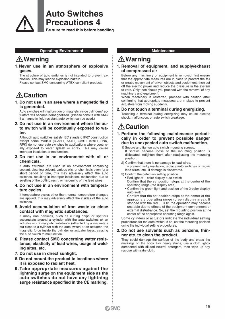
Warning1. Removal of equipment, and supply/exhaust
of compressed airBefore any machinery or equipment is removed, first ensure that the appropriate measures are in place to prevent the fall or erratic movement of driven objects and equipment, then cut off the electric power and reduce the pressure in the system to zero. Only then should you proceed with the removal of any machinery and equipment.When machinery is restarted, proceed with caution after confirming that appropriate measures are in place to prevent actuators from moving suddenly.
2. Do not touch a terminal during energizing.Touching a terminal during energizing may cause electric shock, malfunction, or auto switch breakage.
Caution1. Perform the following maintenance periodi-
cally in order to prevent possible danger due to unexpected auto switch malfunction.1) Secure and tighten auto switch mounting screws.
If screws become loose or the mounting position is dislocated, retighten them after readjusting the mounting position.
2) Confirm that there is no damage to lead wires.To prevent faulty insulation, replace auto switches or repair lead wires, etc., if damage is discovered.
3) Confirm the detection setting position.• Red light of 1-color display auto switch
Confirm that the set position stops at the center of the operating range (red display area).
• Confirm the green light and position of the 2-color display auto switch.Confirm that the set position stops at the center of the appropriate operating range (green display area). If stopped with the red LED lit, the operation may become unstable due to effects of the equipment environment or external disturbance. So, set the mounting position at the center of the appropriate operating range again.
Some cylinders or actuators indicate the individual setting procedures for the auto switch. If so, set the mounting position using the individual setting procedures.
2. Do not use solvents such as benzene, thin-ner etc. to clean the product.They could damage the surface of the body and erase the markings on the body. For heavy stains, use a cloth lightly dampened with diluted neutral detergent, then wipe up any residue with a dry cloth.
Operating Environment
Warning1.Never use in an atmosphere of explosive
gases.The structure of auto switches is not intended to prevent ex-plosion. This may lead to explosion hazard.Please contact SMC concerning ATEX compliant products.
Caution1. Do not use in an area where a magnetic field
is generated.Auto switches will malfunction or magnets inside cylinders/ ac-tuators will become demagnetized. (Please consult with SMC if a magnetic field resistant auto switch can be used.)
2. Do not use in an environment where the au-to switch will be continually exposed to wa-ter.Although auto switches satisfy IEC standard IP67 construction except some models (D-A3, A44, G39, K39, RNK, RPK) do not use auto switches in applications where continu-ally exposed to water splash or spray. This may cause improper insulation or malfunction.
3. Do not use in an environment with oil or chemicals.If auto switches are used in an environment containing coolant, cleaning solvent, various oils, or chemicals even for a short period of time, this may adversely affect the auto switches, resulting in improper insulation, malfunction due to swelling of the potting resin, or hardening of the lead wires.
4. Do not use in an environment with tempera-ture cycles.If temperature cycles other than normal temperature changes are applied, this may adversely affect the insides of the auto switches.
5. Avoid accumulation of iron waste or close contact with magnetic substances.If many iron particles, such as cutting chips or spatters accumulate around a cylinder with the auto switches or an actuator or if a magnetic substance (attracted by a magnet) is put close to a cylinder with the auto switch or an actuator, the magnetic force inside the cylinder or actuator loses, causing the auto switch to malfunction.
6. Please contact SMC concerning water resis-tance, elasticity of lead wires, usage at weld-ing sites, etc.
7. Do not use in direct sunlight.8. Do not mount the product in locations where
it is exposed to radiant heat.9. Take appropriate measures against the
lightning surge on the equipment side as the auto switches do not have any lightning surge resistance specified in the CE marking.
Auto SwitchesPrecautions 4Be sure to read this before handling.
15

1. Keep wiring as short as possible.Be sure to use a wire length of 100 m or less. When the wire length is long, we recommend the ferrite core is attached to the both ends of the cable to prevent excess noise. A contact protection box is not necessary for solid state switches due to the nature of this product construction.
2. Do not exceed the trimmer switch sensor ca-ble length 3 m.If the sensor cable length exceeds 3 m, the CE marking does not apply to the auto switch.
3. Do not use a load that generates surge volt-age.If driving a load such as a relay that generates a surge voltage, use a built-in surge absorbing element type device.
4. Pay attention to the internal voltage drop of the auto switch.Generally, the internal voltage drop of the solid state auto switch is larger than that of the reed auto switch. When the auto switches (“n” pcs.) are connected in series, the voltage drop is multiplied by “n”. In this case, the auto switches operate correctly, but the loads may not operate. Additionally, note that the 12 VDC relay does not apply to the auto switch.
5. Pay attention to leakage current.<2-wire type>Current (leakage current) flows to the load to operate the inter-nal circuit when in the OFF state.
If the criteria given in the above formula are not met, it will not reset correctly (stays ON). Use a 3-wire auto switch if this specification will not be satisfied.Moreover, leakage current flow to the load will be “n” times larger when “n” auto switches are connected in parallel.
6.Output operation of the solid state auto switch is not stable for 50 [ms] after powered ON.In the output operation immediately after powered ON or AND connection operation, the input device (PLC or relay, etc.) may judge the ON position as OFF output or the OFF position as ON output. So, please make the setting on the equipment so that the input judgement signal is set disabled for 50 [ms] im-mediately after powered ON or AND connection. When using SMC’s AHC system (Auto Hand Changing System) Series MA, please also make this setting.
1.Do not allow short-circuit of loads.All models of D-J51, G5NB and PNP output type auto switches do not have built-in short circuit protection circuits. Carefully handle as the auto switch may be damaged.
2.Avoid incorrect wiring.1) If connections are reversed on a 2-wire type auto switch,
the auto switch will not be damaged if protected by a protection circuit, but the auto switch will always stay in an ON state. However, it is still necessary to avoid reversed connections, since the auto switch could be damaged by a load short circuit in this condition.
2) If connections are reversed (power supply line + and power supply line –) on a 3-wire type auto switch, the auto switch will be protected by a protection circuit. However, if the power supply line (+) is connected to the blue wire and the power supply line (–) is connected to the black wire, the auto switch will be damaged.
3. When the lead wire sheath is stripped, con-firm the stripping direction. The insulator may be split or damaged depending on the direction. (D-M9 only)
4. Do not disconnect the cable between the sen-sor and amplifier of the heat resistant 2-color display solid state auto switch by the customer.Even when the sensor and amplifier are connected again, a contact resistance is produced, causing the auto switch to malfunction. Additionally, the sensor and amplifier are paired and they do not operate correctly in different combinations.
Recommended ToolDescription
Wire stripperModel
D-M9N-SWY
∗ Stripper for a round cable (ø2.0) can be used for a 2-wire type cable.
1.Do not use in an area where surges are gen-erated.If there is an equipment unit (electromagnetic lifter, high-fre-quency induction furnace, motor, or radio, etc.) that generates large surges or electromagnetic waves around cylinders with solid state auto switches or actuators, this may cause the cir-cuit element inside the auto switch to break.
Wiring
CautionCaution
Solid State Auto SwitchesPrecautionsBe sure to read this before handling.
Design/Selection
>Operating current of load (OFF condition) Leakage current
Operating Environment
Caution
16

1. Keep wiring as short as possible.As the length of the wiring to a load gets longer, the rush current at switching ON becomes greater, and this may shorten the product’s life. (The switch will stay ON all the time.)1) Use a contact protection box when the wire length is 5 m or
longer.2) Even if an auto switch has a built-in contact protection
circuit, when the wiring is more than 30 m long, it is not able to adequately absorb the rush current and its life may be reduced. It is again necessary to connect a contact protection box in order to extend its life. Please consult with SMC in this case.
2. Do not use a load that generates surge volt-age. If a surge voltage is generated, the discharge occurs at the contact, possibly resulting in the shortening of product life.If driving a load such as a relay that generates a surge volt-age, use an auto switch with built-in contact protection circuit or use a contact protection box.
3. Pay attention to the internal voltage drop of the auto switch.1) Auto switch with an indicator light (Except D-A56, A76H,
A96, A96V, C76, E76A, Z76)• If auto switches are connected in series as shown below,
take note that there will be a large voltage drop because of internal resistance in the light emitting diodes. (Refer to the internal voltage drop in the auto switch specifications.)[The voltage drop will be “n” times larger when “n” auto switches are connected.]Even though an auto switch operates normally, the load may not operate.
• In the same way, when operating under a specified voltage, although an auto switch may operate normally, the load may not operate. Therefore, the formula below should be satisfied after confirming the minimum operat-ing voltage of the load.
2) If the internal resistance of a light emitting diode causes a problem, select an auto switch without an indicator light (D-A6, A80, A80H, A90, A90V, C80, R80, 90, E80A, Z80).
Caution1. Do not allow short-circuit of loads.
If the power is turned ON with a load in a short circuited condition, the auto switch will be instantly damaged because of excess current flow into the switch.
2. Avoid incorrect wiring.A 24 VDC auto switch with indicator light has polarity. The brown lead wire or terminal No. 1 is (+), and the blue lead wire or terminal No. 2 is (–).[For D-97, (+) is on the no-displayed side, (–) is on the black line side.]1) If connections are reversed, an auto switch will operate,
however, the light emitting diode will not light up.Also, take note that a current greater than that specified will damage a light emitting diode and it will no longer operate.Applicable model:D-A73, A73H, A73C, A93, A93V, A53, A54, B53, B54, C73, C73C, E73A, Z73, D-R73, R73C, 97, 93A, A33, A34, A33A, A34A, A44, A44A
2) When using a 2-color indicator type auto switch (D-A79W, A59W and B59W), the auto switch will constantly remain ON if the connections are reversed.
Reed Auto SwitchesPrecautionsBe sure to read this before handling.
Supplyvoltage
– >Internal voltagedrop of auto switch
Minimum operatingvoltage of load
Load
WiringDesign/Selection
Caution
あああ
1.Do not use in an environment where there is excessive impact shock.When excessive impact (300 m/s2 or more) is applied to a reed auto switch during operation, the contact point will mal-function and generate or cut off a signal momentarily (1 ms or less). Please consult with SMC if a solid state auto switch can be used according to the environment.
Operating Environment
Caution
17

Auto Switches Common Specifications
Type
Leakage current
Operating time
Impact resistance
Insulation resistance
Withstand voltage
Ambient temperature
Enclosure
Reed auto switch
None
1.2 ms
300 m/s2
1500 VAC for 1 minute∗1)
(Between lead wire and case)
Solid state auto switch
3-wire: 100 µA or less, 2-wire: 0.8 mA or less
1ms or less∗3)
1000 m/s2 ∗4)
1000 VAC for 1 minute
(Between lead wire and case)
50 MΩ or more (500 VDC measured via megohmmeter) (Between lead wire and case)
−10 to 60°C
IEC60529 Standard IP67∗2)
Refer to the Auto Switch Precautions on pages 8 to 11 before using auto switches.
∗ 1) Electrical entry: Connector type (A73C/A80C/C73C/C80C): 1000 VAC/min.(Between lead wire and the case)
∗ 2) The terminal conduit type (D-A3/A3A/A3C/G39/G39A/G39C/K39/K39A/K39C), DIN terminal type (D-A44/A44A/A44C) and heat resistant auto switch (D-F7NJ) conform to IEC60529 Standard IP63. The trimmer type amplifier section (D-RK) conforms to IP40.
∗ 3) Excluding the solid state auto switches with a timer (D-M5T/G5NT/F7NT/F5NT types) and magnetic field resistant 2-color indication solid state auto switch (D-P3DW/P4DW).The operating time for D-J51 is 2 ms or less and for D-P3DW/P4DW are 40 ms or less.
∗ 4) 980 m/s2 for the trimmer type sensor section, 98 m/s2 for the amplifier section.
Lead wire length indication
L(Example)
Model
D-LC05
D-LC30
D-LC50
Lead wire length
0.5 m
3 m
5 m
Part No. of Lead Wires with Connectors(Applicable only for connector type)
D-M9BW
NilMLZ
N∗1)
SAPCMAPCSBPCMBPCSDPCMDPCLDPC
Length0.5 m1 m3 m5 m
None0.5 m1 m
0.5 m1 m
0.5 m1 m3 m
Tolerance±15 mm±30 mm±90 mm
±150 mm−
±15 mm±30 mm±15 mm±30 mm±15 mm±30 mm±90 mm
Connector Specifications
M8-3 pinPlug connector
M8-4 pinPlug connector
M12-4 pin A code (Normal key)Plug connector
Solid state
∗2)
Reed
−
∗3)
−−−−−−−
Symbol
Lead wire length
:Standard :Produced upon receipt of order (Standard)
∗ 1) Applicable to the connector type (D-C) only.∗ 2) Applicable to the D-M9 (V), D-M9W (V), and D-M9A (V) only.∗ 3) Applicable to the D-B53/B54, D-C73(C)/C80C, D-A93(V), D-A73(C)/A80C, D-
A53/A54, D-Z73, and D-90/97/90A/93A only.∗ 4) For reed auto switches M8 and M12 type with connector, please contact SMC.∗ 5) The standard lead wire length of the trimmer auto switch is 3 m.∗ 6) The standard lead wire length of the solid state auto switch with the timer except
for the D-P3DW and D-M9A (V), water-resistant 2-color display solid state auto switch, wide range detection auto switch, heat resistant 2-color display solid state auto switch, and strong magnetic field resistant 2-color display solid state auto switch is 3 m or 5 m. (Product with a lead wire length of 0.5 m is not avail-able.)
Auto switchmodel
Lead Wire
Lead wires with a connector indication
Prior to UseAuto Switches Common Specifications 1
18

Refer to the Auto Switch Precautions on pages 8 to 11 before using auto switches.
A position (sensor layout position) where the sensitivity is highest on the detection surface of the auto switch enclosure.When the center of the magnet is aligned with this position, this becomes almost the center of the operating range and stable operation can be obtained.
One of elements making up the sequence control.The PLC is so designed that it receives signals, such as auto switch output and outputs them to other devices so as to perform the electrical control according to the preset program.
A temperature range, in which the auto switch can be used.If significant temperature change or freezing occurs even in this temperature range, this may cause the auto switch to malfunction.
A voltage, at which the auto switch can be used.The operating voltage is indicated using generally used voltage (24 VDC or 100 VAC, etc.).For 2-wire type, the operating voltage has the same meaning as the power supply voltage or load voltage.
A range of the current value that can be flowed to the output of the auto switch.If the operating current is lower than this range, the auto switch does not operate correctly. Conversely, if the operating current is higher than this range, this may cause the auto switch to break.
This current value is necessary for the 3-wire type auto switch to operate the circuit through the power cable.For 2-wire type, as the current consumption is a part of the load current, it is not defined.
A resistance between the electric circuit and enclosure.Unless otherwise described particularly, 50MΩ (Min) is used for auto switch.
An auto switch, for which measures against effects arising from external (welding) magnetic field generated in the spot weld-ing process, etc. are taken.The solid state auto switch functions as it detects the frequency of the applied magnetic field. If the external magnetic field (AC) is applied, the last signal is retained not to be affected by the external magnetic field. This system can be used by the cylinder with normal magnetic force.The reed auto switch built-in a magnetic field shielded sensor with a low sensitivity to make the effect of the external mag-netic field (DC or AC magnetic field) insusceptible. Therefore, a dedicated cylinder built-in the strong magnet needs to be selected and there is also an operable range (conditions).
A minimum acceleration that may cause the auto switch to malfunction or break when the standard impact is applied.
A model, long-term water resistance of which is improved by taking structural measures for the general (general purpose) product.
A tolerance dose when the voltage is applied to the portion between the electrical circuit and enclosure.The withstand voltage shows a strength level of the product against the voltage. If a voltage exceeding the withstand voltage is applied, this may cause the product to break. (The voltage described here is different from the power supply voltage nec-essary to operate the product.)
A dimension that shows the mounting position when the position is detected at the stroke end of the cylinder.As this position is set, the maximum sensitivity position is aligned with the center of the magnet. However, make the adjust-ment with the actual machine by considering the characteristic difference during actual setting.When an adjustment allowance is needed for the detection before the stroke, set a value with an adjustment allowance added to the proper mounting position.
A device that is assumed as a target load of the auto switch.
A period of time until the auto switch output becomes stable after the magnetic force to operate the auto switch has been received.
An auto switch operating range in response to the cylinder piston movement (ON length in response to the stroke). The oper-ating range is determined by the magnetic force of the magnet (range, in which the magnetic force acts) and switch sensitivity. So, the operating range may vary as these conditions are changed by the ambient environment, etc.The operating range in the standard status (normal temperature, single cylinder, magnetic force, and sensitivity, etc.) is described in the catalog.
Note) Hysteresis may fluctuate due to the operating environment.Please contact SMC if hysteresis causes an operational problem.
MeaningTerm
Hysteresis
Prior to UseAuto Switches Common Specifications 2
Auto switch
Switch operating position(ON) Hysteresis Reed auto switch: 2 mm or less
Solid state auto switch: 1 mm or less
Switch operating position(OFF)
Most sensitive position
Programmable LogicController (PLC)
Operatingtemperature range
Operating voltage
Operatingcurrent range
Current consumption
Insulation resistance
Magnetic field resistantauto switch
Impact resistance valueWater-resistant type auto switchWithstand voltage
Proper mountingposition
Operating range
Operating timeApplicable load
A deviation amount between the ON position and OFF position caused by auto switch characteristics (difference in sensitivity between ON and OFF).When the switch is turned ON once and the switch (or piston) is moved in the opposite direction, a symptom occurs that the position where the switch turns OFF deviates to a position where it is further returned from the ON po-sition. This deviation amount is called “hysteresis”.
19

Refer to the Auto Switch Precautions on pages 8 to 11 before using auto switches.
A switch that detects the magnetic field by the MR element and incorporates the judgement circuit to turn ON or OFF the out-put regardless of the contact or non-contact of the mechanical contact like transistor (non-contact part).A current that flows to operate the internal circuit when the ON-OFF output is OFF. In particular, if this leak current exceeds the detection current in the 2-wire type auto switch or PLC, this may cause reset fault. So, take great care when selecting a device.A switch that uses the reed switch to detect the magnetic field and turn ON or OFF the output by the contact or non-contact of the mechanical contact (contact part is provided like relay or limit switch).
A load that has the coil. The connection target of the auto switch is a relay.A minimum bending radius (reference value) of the lead wire when the lead wire is secured and constructed (oscillation or ro-tation is not considered).(As the temperature or current value conforms to the auto switch specifications, this lead wire bending radius differs from the value disclosed by the electric wire manufacturer.)A structure, in which the lead wire of the auto switch is taken out in the horizontal direction when the cylinder is laid out hori-zontally (cylinder rod is horizontal), is called “in-line entry”. A structure, in which the lead wire is taken out in a direction per-pendicular to the cylinder axis center, is called “perpendicular entry”.
MeaningTerm
Minimum Stroke forAuto Switch Mounting
Internal voltage drop
Solid state auto switch
Leak current
Reed auto switch
Induction loadRecommended leadwire bending radius
Electrical entry
2-Color Indication
Load
Load current
Enclosure
IP
First characteristic numeral
Second characteristic numeral
Example) In the case of stipulated as IP65, we can know the degrees of protection is dusttight and water jet-proof on the grounds that the first characteristic numeral is 6 and the second characteristic numeral is 5 respectively, that gives it will not be adversely affected by direct water jets from any direction.
Non-protectedProtected against vertically falling water dropsProtected against vertically falling water drops when enclosure tilted up to 15°Protected against rainfall when enclosure tilted up to 60°Protected against splashing waterProtected against water jetsProtected against powerful water jetsProtected against the effects of temporary immersion in waterProtected against the effects of continuous immersion in water
01
2
345678
Second Characteristics: Degrees of protection against water
Non-protectedProtected against solid foreign objects of 50 mm ø and greaterProtected against solid foreign objects of 12 mm ø and greaterProtected against solid foreign objects of 2.5 mm ø and greaterProtected against solid foreign objects of 1.0 mm ø and greaterDust-protectedDusttight
0123456
First Characteristics: Degrees of protection against solid foreign objects
A minimum stroke value of the auto switch that can be mounted on the cylinder.The minimum stroke is determined by the specification limit (auto switch operation or position setting ability, etc.) and physi-cal limit (mechanical interference associated with the auto switch mounting).Note that the catalog shows the value assuming that the position detection is performed at the stroke end and this value does not consider the adjustment allowance.When an adjustment allowance is needed, such as detection before the stroke, a value is set that this adjustment allowance is added to the minimum stroke.
A voltage that is applied to the portion between the COM and signal line when the auto switch is ON.As only a value that the internal voltage drop is subtracted from the power supply voltage is applied to the input side of the PLC, the detection fault (incorrect input) may occur if this value is lower than the minimum operating voltage. So, take great care when selecting a device.
As the end part of the auto switch operating range (boundary between ON and OFF) is an area where is susceptible to the external disturbance or stroke change during cylinder operation, this function is intended to quickly and properly make the setting at the center of the operating range where the stable operation can be obtained by changing the operation indication color of the auto switch.
A device that is connected to the output of the auto switch so as to do any work is called “load”.For example, the load is a relay or PLC, etc.To check the operation of the auto switch, a device equivalent to the load (such as resistor, etc.) is connected.
A current that flows to the load when the ON-OFF output is ON.
A class of protection against solid or water entry of the electrical machinery and apparatus specified in IEC60529.
Prior to UseAuto Switches Common Specifications 3
20
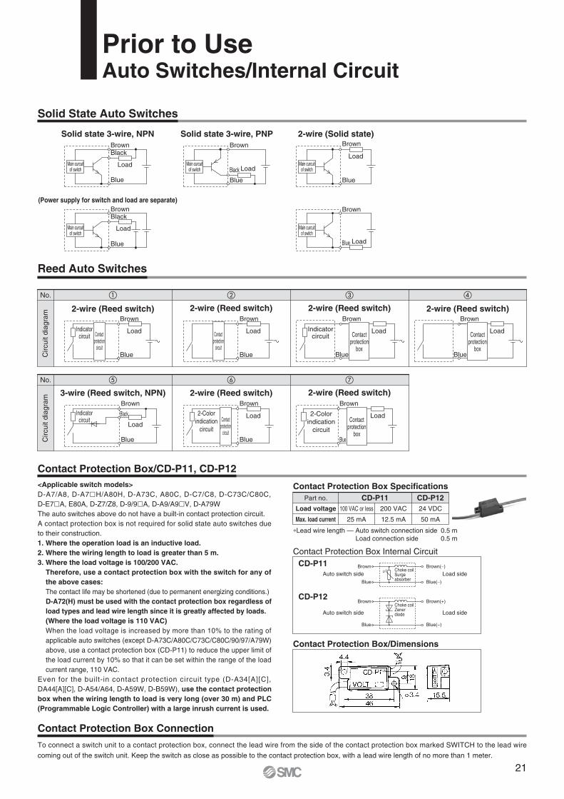
Reed Auto Switches
Solid State Auto Switches
Contact Protection Box/CD-P11, CD-P12
Contact Protection Box SpecificationsPart no.
Load voltage
Max. load current
CD-P11 CD-P12
∗Lead wire length — Auto switch connection side 0.5 m Load connection side 0.5 m
100 VAC or less
25 mA
200 VAC
12.5 mA
24 VDC
50 mA
To connect a switch unit to a contact protection box, connect the lead wire from the side of the contact protection box marked SWITCH to the lead wire
coming out of the switch unit. Keep the switch as close as possible to the contact protection box, with a lead wire length of no more than 1 meter.
Contact Protection Box Connection
Contact Protection Box/Dimensions
Contact Protection Box Internal CircuitCD-P11
CD-P12
<Applicable switch models>D-A7/A8, D-A7H/A80H, D-A73C, A80C, D-C7/C8, D-C73C/C80C, D-E7A, E80A, D-Z7/Z8, D-9/9A, D-A9/A9V, D-A79WThe auto switches above do not have a built-in contact protection circuit.A contact protection box is not required for solid state auto switches due to their construction.1. Where the operation load is an inductive load.2. Where the wiring length to load is greater than 5 m.3. Where the load voltage is 100/200 VAC.
Therefore, use a contact protection box with the switch for any of the above cases:The contact life may be shortened (due to permanent energizing conditions.)D-A72(H) must be used with the contact protection box regardless of load types and lead wire length since it is greatly affected by loads.(Where the load voltage is 110 VAC)When the load voltage is increased by more than 10% to the rating of applicable auto switches (except D-A73C/A80C/C73C/C80C/90/97/A79W) above, use a contact protection box (CD-P11) to reduce the upper limit of the load current by 10% so that it can be set within the range of the load current range, 110 VAC.
Even for the built-in contact protection circuit type (D-A34[A][C], DA44[A][C], D-A54/A64, D-A59W, D-B59W), use the contact protection box when the wiring length to load is very long (over 30 m) and PLC (Programmable Logic Controller) with a large inrush current is used.
2-Colorindication
circuit
2-wire (Reed switch)
Load
2-wire (Reed switch)
Load2-Colorindication
circuitLoad
Black
2-wire (Reed switch)
LoadContactprotection
box
Contactprotection
box
Contactprotection
box
2-wire (Reed switch)
Load
3-wire (Reed switch, NPN)
Indicatorcircuit
Indicatorcircuit
2-wire (Reed switch)
LoadContactprotection
circuit
Contactprotection
circuit
Contactprotection
circuit
2-wire (Reed switch)
Load
Brown
Blue Blue
Blue
(Power supply for switch and load are separate)
2-wire (Solid state)Solid state 3-wire, PNPSolid state 3-wire, NPN
Load
Load
LoadLoad
Load
Blue
BlueBlue
Black
Blue
Black
Blue
BlackBrown Brown Brown
BrownBrown
Main curcuitof switch
Main curcuitof switch
Main curcuitof switch
Main curcuitof switch
Main curcuitof switch
No.
Circ
uit d
iagr
amC
ircui
t dia
gram
No.
Brown
Blue Blue(−)
Brown(+)
Load sideAuto switch sideChoke coilZenerdiode
Brown
Blue Blue(∼)
Brown(∼)
Load sideAuto switch sideChoke coilSurgeabsorber
Indicatorcircuit
Brown Brown
BrownBrownBrown
Brown
Blue
Blue
Blue
Blue
21
Prior to UseAuto Switches/Internal Circuit

Relay
Relay
Input
COM
COM
Input
COM
Input
COM
Input
2-wire OR connection2-wire AND connection
3-wire OR connection for PNP output
(Performed with auto switches only)(Using relays)
3-wire AND connection for PNP output
3-wire OR connection for NPN output(Performed with auto switches only)(Using relays)
3-wire AND connection for NPN output
(PLC internal circuit)
(PLC internal circuit)
(PLC internal circuit)
(PLC internal circuit)
2-wire
3-wire, PNP
2-wire
3-wire, NPN
Load
Load
Load
Load Load
Load Load
Load
Blue
Black
Brown
Auto switch 2
Blue
Black
Brown
Auto switch 1
Blue
Black
Brown
Auto switch 2
Blue
Black
Brown
Auto switch 1
Blue
Black
Brown
Auto switch 2
Blue
Black
Brown
Auto switch 1
Blue
Black
Brown
Auto switch 2
Blue
Black
Brown
Auto switch 1
Blue
Brown
Auto switch 2
Blue
Brown
Auto switch 1
Blue
Black
Brown
Auto switch 2
Blue
Black
Brown
Auto switch 1
Blue
Brown
Auto switch 2
Blue
Brown
Auto switch 1
Blue
Black
Brown
Auto switch 2
Blue
Black
Brown
Auto switch 1
Blue
Brown
Blue
Brown
Blue
Black
Brown
Blue
Black
Brown
Auto switch
Auto switch
Auto switch
Auto switch
Prior to UseAuto Switch Connection and Example
Example of AND (Series) and OR (Parallel) Connection
Sink Input Specifications Source Input Specifications
Load voltage at ON = Power supply voltage – Residual voltage x 2 pcs.
= 24 V − 4 V x 2 pcs.= 16 V
Example: Power supply is 24 VDCInternal voltage drop in auto switch is 4 V.
Load voltage at OFF = Leakage current x 2 pcs. x Load impedance
= 1 mA x 2 pcs. x 3 kΩ= 6 V
Example: Load impedance is 3 kΩ.Leakage current from auto switch is 1 mA.
(Solid state) (Reed auto switch)When two auto switches are connected in series, a load may malfunction because the load voltage will decline when in the ON state.The indicator lights will light up when both of the auto switches are in the ON state.Auto switches with load voltage less than 20V cannot be used.
When two auto switches are connected in parallel, malfunction may occur because the load voltage will increase when in the OFF state.
Because there is no current leakage, the load voltage will not increase when turned OFF. However, depending on the number of auto switches in the ON state, the indicator lights may sometimes grow dim or not light up, due to the dispersion and reduction of the current flowing to the auto switches.
Connect according to the applicable PLC input specifications, as the connection method will vary depending on the PLC input specifications.
∗ When using solid state auto switches, ensure the application is setup so the signals for the first 50 ms are invalid.
22