Series 100 Valves Technical Data - Dorot Control Valves€¦ · · 2017-12-17Technical Data...
6
Series 100 Valves Edition 10/2017 6 Technical Data Available Models Pattern Type 44 45 53 47 87 77 82 84 53A 91 67 94 Connection Threaded Threaded Victaulic® Flanged Flanged Flanged Flanged Threaded Victaulic® Threaded Flanged Threaded Material Cast Iron Bronze Cast Iron Cast Iron Bronze Ductile Iron Cast Iron Cast Iron Cast Iron Bronze Ductile Iron Ductile Iron Max. Pressure 16bar / 250psi 25bar / 360psi Available Sizes mm inch 20 3 /4 ● ● 25 1 ● ● 40 1 1 /2 ● ● ● ● ● 50 2 ● ● ● ● ● ● ● ● ● ● 65 2 1 /2 ● ● ● 80R 3R ● ● ● ● ● ● 80 3 ● ● ● ● ● ● ● ● ● ● 100 4 ● ● ● ● ● ● ● 150 6 ● ● ● ● ● ● 200R 8R ● ● ● 200 8 ● ● ● ● 250 10 ● ● ● ● 300 12 ● ● ● 350 14 ● ● ● 400 16 ● ● 450 18 ● ● 500 20 ● ● 600 24 ● ● Design Specifications Materials Standard Optional * Body and Bonnet Cast Iron, Ductile Iron, Bronze Cast Steel, Stainless Steel Diaphragm Natural Rubber NBR ,EPDM ,Neoprene Spring SST 302 SST 316 Nuts And Bolts Coated Steel SST Coating Polyester Epoxy, Nylon, Rubber * Others Upon Request Non Standard Bonnets Connections Standard Optional * Flanges ISO 2084, 2441, 5752 ANSI B16 JIS B22 AS 10 Threads F-BSP F-NPT Control Bores 1/8”,1/4”,1/2” NPT Throttling Bonnet Position Indicating Bonnet
Transcript of Series 100 Valves Technical Data - Dorot Control Valves€¦ · · 2017-12-17Technical Data...

Series 100 Valves
Edition 10/2017
6
Technical Data
Available Models
Pattern
Type 44 45 53 47 87 77 82 84 53A 91 67 94Connection Threaded Threaded Victaulic® Flanged Flanged Flanged Flanged Threaded Victaulic® Threaded Flanged Threaded
Material Cast Iron Bronze Cast Iron Cast Iron Bronze Ductile Iron Cast Iron Cast Iron Cast Iron Bronze Ductile Iron Ductile IronMax. Pressure 16bar / 250psi 25bar / 360psi
Avail
able
Size
s
mm inch20 3/4 ● ●25 1 ● ●40 11/2 ● ● ● ● ●50 2 ● ● ● ● ● ● ● ● ● ●65 21/2 ● ● ●
80R 3R ● ● ● ● ● ●80 3 ● ● ● ● ● ● ● ● ● ●
100 4 ● ● ● ● ● ● ●150 6 ● ● ● ● ● ●200R 8R ● ● ●200 8 ● ● ● ●250 10 ● ● ● ●300 12 ● ● ●350 14 ● ● ●400 16 ● ●450 18 ● ●500 20 ● ●600 24 ● ●
Design Specifications
Materials Standard Optional *
Body and Bonnet Cast Iron, Ductile Iron, Bronze
Cast Steel, Stainless Steel
Diaphragm Natural Rubber NBR ,EPDM ,Neoprene
Spring SST 302 SST 316
Nuts And Bolts Coated Steel SST
Coating Polyester Epoxy, Nylon, Rubber* Others Upon Request
Non Standard Bonnets
Connections Standard Optional *
Flanges ISO 2084, 2441, 5752 ANSI B16JIS B22AS 10
Threads F-BSP F-NPT
Control Bores 1/8”,1/4”,1/2” NPT
Throttling Bonnet Position Indicating Bonnet

Series 100 Valves
Edition 10/2017
7
Technical Data
Diaphragm Selection Table*
Diameter Type No. Pressure Range
mm inch mwc psi
20, 25 3/4”, 1” Standard 18 12-160 17-250Low Pressure 85 5-100 7-140
40 11/2”Standard 13 12-160 17-250
S. Low Pressure 82 5-50 7-70
50, 65, 80R 2”, 21/2”, 3R
Standard 03 15-160 21-250EPDM for potable-water use 198 15-160 21-250
Low Pressure 02 7-100 10-140S. Low Pressure 12 4-50 6-70
Extreme 60 20-160 28-25050HP 2”HP High Pressure 69 10-250 15-360
80, 100 3”, 4”
Standard 32 12-160 17-250EPDM for potable-water use 199 12-160 17-250
Low Pressure 05 4-100 6-140Extreme 61 20-160 28-250
80HP 3”HP High Pressure 70 10-250 15-360100HP 4”HP High Pressure 71 10-250 15-360
150, 200R 6”, 8R
Standard 62 20-160 28-250EPDM for potable-water use 200 20-160 28-250
Low Pressure 09 5-100 7-140S. Low Pressure 91 2-60 3-85
150HP 6”HP High Pressure 72 10-250 15-360
200, 300, 350 8”, 12”, 14”
Standard 36 7-160 10-250EPDM for potable-water use 326 7-160 10-250
Low Pressure 37 2-100 3-140Extreme 63 20-160 28-250
200HP 8”HP High Pressure 73 10-250 15-360
250 10”Standard 40 7-160 10-250
EPDM for potable-water use 360 7-160 10-250Low Pressure 50 2-50 3-70
250HP, 400HP, 500HP, 600HP
10”HP, 16”HP, 20”HP, 24”HP
High Pressure 78 10-250 15-360Low Pressure 92 2-100 3-140
* Standard Diaphragm: Nylon Reinforced Natural Rubber.Optional diaphragm materials such as NBR, Neoprene, EPDM etc. are available. These include potable-water compatible diaphragms for different pressure-ratings and valve-models other than the ones specified above.
** HP = High Pressure
Pressure RatingPressure rating of series 100 valves is body strength, connection standard and diaphragm type.Pressure rating of valve body of standard models: 16 Bar / 250 psi.Pressure rating of valve body of high pressure models: 25 Bar / 360 psi.Connection standard is marked on the identification plate, assembled on the valve body.Diaphragms operation pressure range is presented at the above table.
Series 100 Valves
Edition 10/2017
8
Technical Data
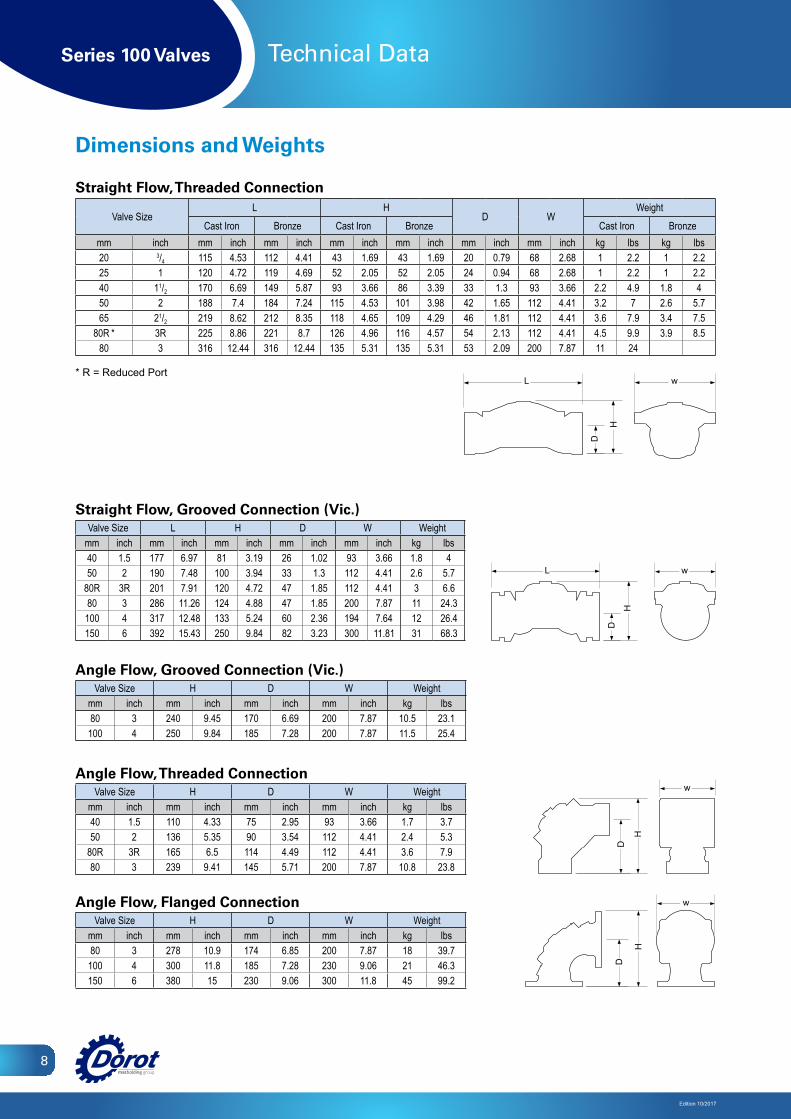
Dimensions and Weights
Straight Flow, Threaded Connection
Valve SizeL H
D WWeight
Cast Iron Bronze Cast Iron Bronze Cast Iron Bronzemm inch mm inch mm inch mm inch mm inch mm inch mm inch kg lbs kg lbs20 3/4 115 4.53 112 4.41 43 1.69 43 1.69 20 0.79 68 2.68 1 2.2 1 2.225 1 120 4.72 119 4.69 52 2.05 52 2.05 24 0.94 68 2.68 1 2.2 1 2.240 11/2 170 6.69 149 5.87 93 3.66 86 3.39 33 1.3 93 3.66 2.2 4.9 1.8 450 2 188 7.4 184 7.24 115 4.53 101 3.98 42 1.65 112 4.41 3.2 7 2.6 5.765 21/2 219 8.62 212 8.35 118 4.65 109 4.29 46 1.81 112 4.41 3.6 7.9 3.4 7.5
80R * 3R 225 8.86 221 8.7 126 4.96 116 4.57 54 2.13 112 4.41 4.5 9.9 3.9 8.580 3 316 12.44 316 12.44 135 5.31 135 5.31 53 2.09 200 7.87 11 24
* R = Reduced Port
Straight Flow, Grooved Connection (Vic.)Valve Size L H D W Weight
mm inch mm inch mm inch mm inch mm inch kg lbs40 1.5 177 6.97 81 3.19 26 1.02 93 3.66 1.8 450 2 190 7.48 100 3.94 33 1.3 112 4.41 2.6 5.7
80R 3R 201 7.91 120 4.72 47 1.85 112 4.41 3 6.680 3 286 11.26 124 4.88 47 1.85 200 7.87 11 24.3100 4 317 12.48 133 5.24 60 2.36 194 7.64 12 26.4150 6 392 15.43 250 9.84 82 3.23 300 11.81 31 68.3
Angle Flow, Grooved Connection (Vic.)Valve Size H D W Weight
mm inch mm inch mm inch mm inch kg lbs80 3 240 9.45 170 6.69 200 7.87 10.5 23.1
100 4 250 9.84 185 7.28 200 7.87 11.5 25.4
Angle Flow, Threaded ConnectionValve Size H D W Weight
mm inch mm inch mm inch mm inch kg lbs40 1.5 110 4.33 75 2.95 93 3.66 1.7 3.750 2 136 5.35 90 3.54 112 4.41 2.4 5.3
80R 3R 165 6.5 114 4.49 112 4.41 3.6 7.980 3 239 9.41 145 5.71 200 7.87 10.8 23.8
Angle Flow, Flanged ConnectionValve Size H D W Weight
mm inch mm inch mm inch mm inch kg lbs80 3 278 10.9 174 6.85 200 7.87 18 39.7
100 4 300 11.8 185 7.28 230 9.06 21 46.3150 6 380 15 230 9.06 300 11.8 45 99.2
w
H
L
D
w
D
H
L
H
D
w
H
D
w
w
H
L
Dw
D
H
LH
D
w
H
D
w
w
H
L
D
w
D
H
L
H
D
w
H
D
w
w
H
L
D
w
D
H
L
H
D
w
H
D
w

Series 100 Valves
Edition 10/2017
9
Technical Data
Dimensions and Weights
Straight Flow, Flanged Connection - Standard Models 16 Bar / 250 psi
Valve Size L H D WWeight
Cast Iron Duct. Iron Bronzemm inch mm inch mm inch mm inch mm inch kg lbs kg lbs kg lbs40 11/2 186 7.32 153 6.02 76.5 3.01 76.5 3.01 5.8 13 6.2 14 6.5 14.350 2 200 7.87 166 6.54 85 3.35 166 6.54 7.2 15.8 7.7 17 8 17.665 21/2 214 8.43 185 7.28 92.5 3.64 185 7.28 10.3 22.7 10.3 22.7
80R 3R 200 7.87 202 7.95 105 4.13 200 7.87 11 24.3 11.8 2680 3 285 11.22 200 7.87 105 4.13 200 7.87 17 37.5 18.2 40.1 19 42100 4 305 12.01 230 9.06 110 4.33 230 9.06 22 48.5 24 53 24 53150 6 390 15.35 314 12.36 145 5.71 300 11.8 46 101 49 108 51 112
200R 8R 385 15.16 350 13.78 170 6.69 365 14.4 50 110 54 119200 8 460 18.11 400 15.75 170 6.69 365 14.4 80 176 86 190 89 196250 10 535 21.06 445 17.52 205 8.07 440 17.3 117 258 125 276 131 289300 12 580 22.83 495 19.49 240 9.45 490 19.3 156 344 167 368 147 324350 14 580 22.83 495 19.49 270 10.6 530 20.9 182 401 172 379 180 397
Straight Flow, Flanged Connection - High Pressure Models 25 Bar / 360 psiValve Size L H D W Weight
mm inch mm inch mm inch mm inch mm inch kg lbs50 2 228 8.98 169 6.65 85 3.35 175 6.9 10 22
50TH 2TH 250 8.98 120 6.65 42 1.65 175 6.9 6 1365 21/2 233 9.18 185 7.28 92.5 3.64 185 7.28 14.5 3280 3 310 12.2 237 9.33 105 4.13 200 7.87 30 66.1100 4 356 14.02 263 10.35 120 4.72 260 10.24 38 83.8150 6 436 17.17 378 14.88 150 5.91 320 12.6 75 165.3200 8 530 20.87 481 18.94 180 7.09 400 15.75 123 271250 10 636 25.04 546 21.5 215 8.46 495 19.49 190 419400 16 709 27.91 830 32.68 310 12.2 830 32.68 433 955450 18 715 28.15 830 32.68 340 13.39 830 32.68 460 1014500 20 900 35.43 970 38.19 490 19.29 980 38.58 674 1486600 24 900 35.43 970 38.19 490 19.29 980 38.58 696 1534
* TH = Threaded
L
D
H
w
D
H
wL
L
D
H
w
D
H
wL
L
D
H
w
D
H
wL
L
D
H
w
D
H
wL

Series 100 Valves
10
Edition 10/2017
Technical Data
Hydraulic Performance
Valve Sizemm 20 25 40 50 65 80R 80 100 150 200R 200 250 300 350 400 450 500 600inch 3/4 1 11/2 2 21/2 3R 3 4 6 8R 8 10 12 14 16 18 20 24
Max. Flow Continuance
m3/hr 6 10 25 40 40 40 100 160 350 350 620 970 1400 1400 2500 2500 3890 5500gpm 26.4 44 110 176 176 176 440 700 1540 1540 2730 4268 6160 6160 11000 11000 17116 24200
Max. Flow Intermittent
m3/hr 16 27 68 109 109 109 245 273 955 955 1309 2645 3818 3818 6818 6818 10609 10609gpm 72 120 300 480 480 480 1080 1200 4200 4200 5760 11640 16800 16800 30000 30000 46680 46680
Minimal Flowm3/hr < 1gpm < 5
Kv m3/hr @ 1 bar 17 17 64 95 95 95 170 220 600 670 800 1250 1900 1900 2600 2600 4600 4600Cv gpm @ 1 psi 20 20 75 110 110 110 200 260 700 780 930 1460 2220 2220 3030 3030 5370 5370Kv* m3/hr @ 1 bar - - - 78 - - 120 200 550 - 800 1300 - - 2600 2600 4600 4600Cv* gpm @ 1 psi - - - 91 - - 140 230 640 - 930 1520 - - 3030 3030 5370 5370
* High pressure models
Cavitation Data
Ups
tream
Pre
ssur
e
Downstream Pressure
3/4” 1
”
1 1/2”
2”, 2
1/2”, 3
R
3” 4”, 5”
6”, 8R
10”
12”, 1
4”16
”, 18”
20”, 2
4”
8”
2
3
456789
10
2
3
4
56789
10
1 10 100 1000 5000
10000100010010
350
300
250
200
150
100
50
25
20
15
10
5
00 1 2 3 4 5 6 7 8
10 20 30 40 50 60 70 80 90 100 110barpsi
psi bar
m3/hrgpm
psi
P (Bar) = KvQ[ ] 2
)( P (Psi) = CvQ[gpm] 2
)(m3
hr
mwcHeadloss Chart
3/4” 1
”
1 1/2”
2”, 2
1/2”, 3
R
3” 4”, 5”
6”, 8R
10”
12”, 1
4”16
”, 18”
20”, 2
4”
8”
2
3
456789
10
2
3
4
56789
10
1 10 100 1000 5000
10000100010010
350
300
250
200
150
100
50
25
20
15
10
5
00 1 2 3 4 5 6 7 8
10 20 30 40 50 60 70 80 90 100 110barpsi
psi bar
m3/hrgpm
psi
P (Bar) = KvQ[ ] 2
)( P (Psi) = CvQ[gpm] 2
)(m3
hr
mwc
Safe zone for Bronze valves
Cavitation zone
Safe operationzone

Series 100 Valves
Edition 10/2017
11
Technical Data
ComponentsComponent No. Description
1 Body
2 Bonnet
3 Diaphragm
4 Spring
5 Spring Disc
6 Bolt
7 Short Bolt
8 Washer
9 Nut
10 Suspension Ring (Hook)
Main Components
Pilot valves for superb regulation at high reliability
Internal SST spring:allows the use of wide range of diaphragmrubber types
Polymeric coating, UV and corrosion resistant
Wide materialsvariety
Flexible reinforoeddiaphragm-nobearing, guides orinternal seals used
Unique DesignCreating low losses at high flow rates
2
3
4 569810 7
1
3
1245689
3
12
3
45689
2
3
4 569810 7
1
3
1245689
3
12
3
45689
2
3
4 569810 7
1
3
1245689
3
12
3
45689