
Serial NoTender No.SDPO/DMN/PMSUT AAP 10 …daman.gov.in/tenders/2012/police_department/B P...
26
ADMINISTRATION OF DAMAN & DIU (U.T) POLICE DEPARTMENT, DAMAN & DIU DAMAN Serial No....Tender No.SDPO/DMN/PMSUT AAP 10-11/Bullet Proof Jacket/2012/569 Serial No. Price 1000/- TENDERFORM A) Tender reference No. : - DIGP/DMN/PMSUT AAP 09-10 & 10-11/Bullet Proof Jacket/2012/569 B) Date of issue Tender: - From 20/11/2012 C) Date of submissionof Tender:-From 07/12/2012,15.00 hours during office hours D) Date of Technical Bid opening: - From 11/12/2012, 15.30hours E) Validity of Tender :- 120 days from the date of opening of tender F) Seri al o. Item Tendered Quantity in Nos. Tender Document Fee 1 BULLET PROOF JACKET :- AS PER SPECIFICATIONS ATTACHED ALONGWITH 06 1000/- TermsandConditions :- (1) T enders are invited in ‘Two Envelope System’ (Technical Bid & Commercial Bid) Tenderer can download the tender form and specifications from the www.daman.nic.in or www.ddpolice.gov.in . (2) Tenderer has to submit separate Demand Drafts towards Tender Document Fees and Earnest Money Deposit (wherever applicable) in the name of “Dy. Inspector General of Police” payable at Daman on or before 15.00 hours on 07.12.2012 ( The reference and equipment name should be written on envelope.) This envelope should be submitted at the O/o the Sub Divisional Police Officer, PHQ, Airport Road, Daman 396 210. The Technical Bid envelope shall accompany a scanned copy of Demand Drafts. If Tenderer fails to submit tender document fees in the form of Demand Draft, his offer will be rejected. The tender document fees will not be refunded under any circumstances.
Transcript of Serial NoTender No.SDPO/DMN/PMSUT AAP 10 …daman.gov.in/tenders/2012/police_department/B P...

ADMINISTRATION OF DAMAN & DIU (U.T)POLICE DEPARTMENT, DAMAN & DIU
DAMAN
Serial No....Tender No.SDPO/DMN/PMSUT AAP 10-11/Bullet Proof Jacket/2012/569
Serial No. Price 1000/-TENDERFORM
A) Tender reference No. : - DIGP/DMN/PMSUT AAP 09-10 & 10-11/Bullet Proof Jacket/2012/569
B) Date of issue Tender: - From 20/11/2012
C) Date of submission of Tender:-From 07/12/2012,15.00 hours during office hours
D) Date of Technical Bid opening: - From 11/12/2012, 15.30hours
E) Validity of Tender :- 120 days from the date of opening of tender
F)
Serialo.
Item Tendered Quantity inNos.
TenderDocument Fee
1 BULLET PROOF JACKET :-
AS PER SPECIFICATIONSATTACHED ALONGWITH
061000/-
TermsandConditions :-
(1) T enders are invited in ‘Two Envelope System’ (Technical Bid & Commercial
Bid) Tenderer can download the tender form and specifications from the www.daman.nic.in orwww.ddpolice.gov.in.
(2) Tenderer has to submit separate Demand Drafts towards Tender Document Fees and
Earnest Money Deposit (wherever applicable) in the name of “Dy. Inspector General of
Police” payable at Daman on or before 15.00 hours on 07.12.2012 ( The reference and
equipment name should be written on envelope.) This envelope should be submitted at the
O/o the Sub Divisional Police Officer, PHQ, Airport Road, Daman 396 210. The Technical
Bid envelope shall accompany a scanned copy of Demand Drafts. If Tenderer fails to
submit tender document fees in the form of Demand Draft, his offer will be rejected. The
tender document fees will not be refunded under any circumstances.
(3) Tenderers are requested to submit their bid in two separate envelopes marked as “Technical
Envelope” and “Commercial Envelope” .
(4) The various activities required to be executed by the Bidders to submit their Bids for these
items have time and date limit. The Bidders are requested to execute all the activities
related to their bids within the prescribed time limits. Tender Inviting Authority shall not
be responsible for any delay.
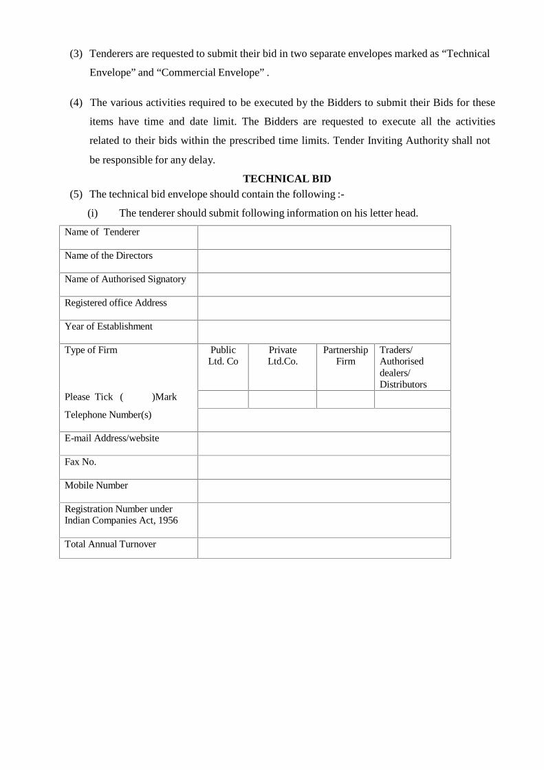
TECHNICAL BID(5) The technical bid envelope should contain the following :-
(i) The tenderer should submit following information on his letter head.
Name of Tenderer
Name of the Directors
Name of Authorised Signatory
Registered office Address
Year of Establishment
Type of Firm PublicLtd. Co
PrivateLtd.Co.
PartnershipFirm
Traders/Authoriseddealers/Distributors
Please Tick ( )Mark
Telephone Number(s)
E-mail Address/website
Fax No.
Mobile Number
Registration Number underIndian Companies Act, 1956
Total Annual Turnover
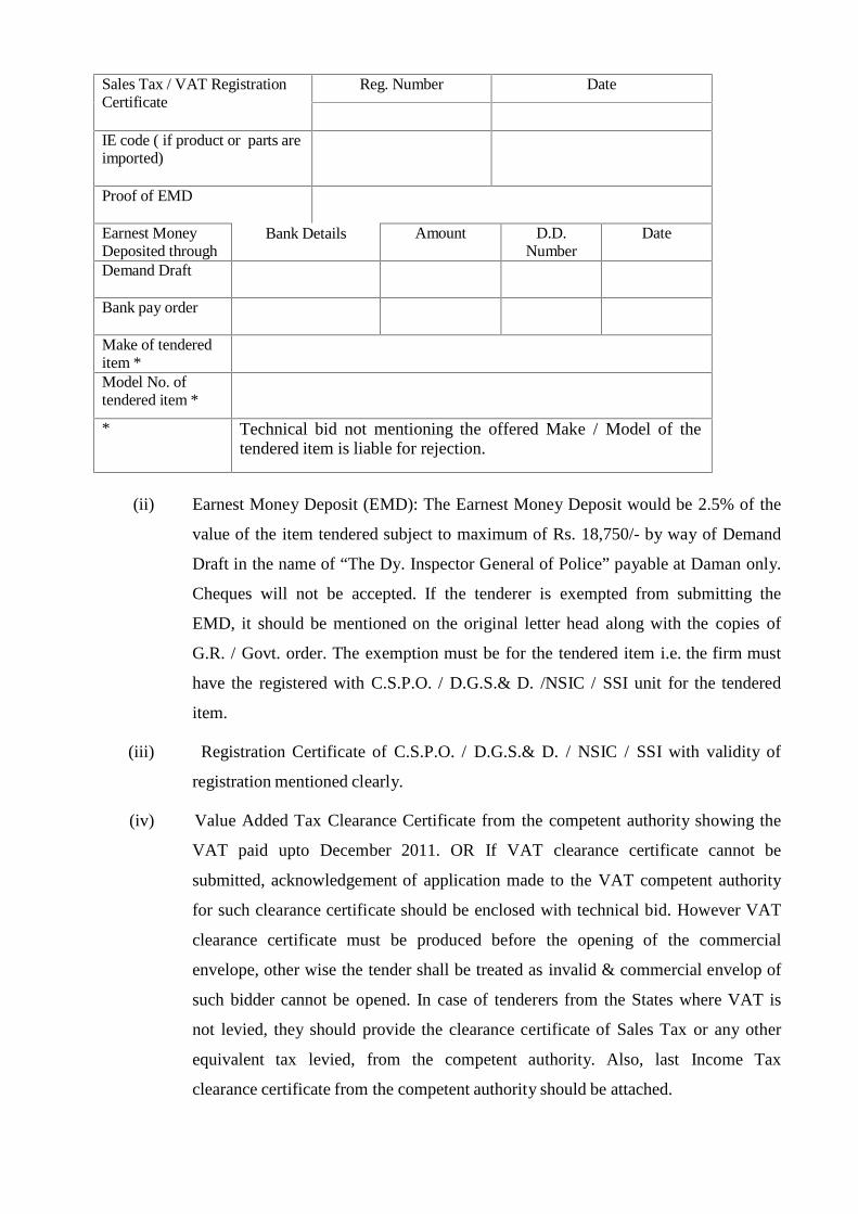
Sales Tax / VAT RegistrationCertificate
Reg. Number Date
IE code ( if product or parts areimported)
Proof of EMD
Earnest MoneyDeposited through
Bank Details Amount D.D.Number
Date
Demand Draft
Bank pay order
Make of tendereditem *Model No. oftendered item *
* Technical bid not mentioning the offered Make / Model of thetendered item is liable for rejection.
(ii) Earnest Money Deposit (EMD): The Earnest Money Deposit would be 2.5% of the
value of the item tendered subject to maximum of Rs. 18,750/- by way of Demand
Draft in the name of “The Dy. Inspector General of Police” payable at Daman only.
Cheques will not be accepted. If the tenderer is exempted from submitting the
EMD, it should be mentioned on the original letter head along with the copies of
G.R. / Govt. order. The exemption must be for the tendered item i.e. the firm must
have the registered with C.S.P.O. / D.G.S.& D. /NSIC / SSI unit for the tendered
item.
(iii) Registration Certificate of C.S.P.O. / D.G.S.& D. / NSIC / SSI with validity of
registration mentioned clearly.
(iv) Value Added Tax Clearance Certificate from the competent authority showing the
VAT paid upto December 2011. OR If VAT clearance certificate cannot be
submitted, acknowledgement of application made to the VAT competent authority
for such clearance certificate should be enclosed with technical bid. However VAT
clearance certificate must be produced before the opening of the commercial
envelope, other wise the tender shall be treated as invalid & commercial envelop of
such bidder cannot be opened. In case of tenderers from the States where VAT is
not levied, they should provide the clearance certificate of Sales Tax or any other
equivalent tax levied, from the competent authority. Also, last Income Tax
clearance certificate from the competent authority should be attached.
(v) The tenderer should be an authorized distributor / dealer for the tendered item and he
should furnish current year valid Authorization Letter / Dealerships certificates
from the Original Equipment Manufacturer (OEM). The Authorization letter should
be specific for the tendered item. Xerox copy of Authorization letter should be
attested with valid dates. The name of item should be clearly mentioned in
Authorization Letter. (Original authorization letter should be submitted for
verification at the time of commercial bid opening).
(vi) The tenderer should obtain a letter from the manufacturer that the Model quoted in
the tender conforms to the specifications of the products manufactured as on date
and latest. Also the product should not be of old model and service be provided for
the period as mentioned in the specifications, or upto 03 years whichever is higher
from the date of acceptance of stores /date of installation. Also a letter showing that
he is an authorized distributor/ dealer for a minimum period of next 3 years.
(vii) Power of Attorney in favour of person signing the bids to be given in Technical
envelope (if applicable)
(viii) Product Brochure clearly mentioning the features, Make/Model No. etc. If Brochure
is not available then Photograph of tendered product should be submitted.
(ix) Latest Test Report alongwith letter of the tenderer giving technical specifications to
the laboratory asking for latest report i.e. on or after December 2011, of the
tendered item should be submitted.
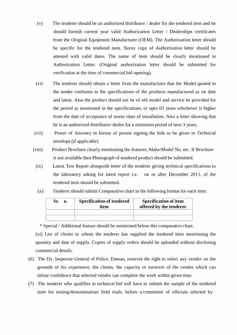
(x) Tenderer should submit Comparative chart in the following format for each item.
Sr. o. Specification of tendereditem
Specification of itemoffered by the tenderer
* Special / Additional feature should be mentioned below this comparative chart.
(xi) List of clients to whom the tenderer has supplied the tendered item mentioning the
quantity and date of supply. Copies of supply orders should be uploaded without disclosing
commercial details.
(6) The Dy. Inspector General of Police, Daman, reserves the right to select any vendor on the
grounds of his experience, the clients, the capacity or turnover of the vendor which can
infuse confidence that selected vendor can complete the work within given time.
(7) The tenderer who qualifies in technical bid will have to submit the sample of the tendered
item for testing/demonstration/ field trials, before a committee of officials selected by
Dy. Inspector General of Police, Daman within four days positively from opening of
technical envelop, on 'No cost, No commitment' basis. If the tenderer fails in/ to show the
demonstration/ field trials within given period, his offer will be liable to disqualify.
(8) The tenderer shall give an undertaking for supply of spare parts / batteries for the period
specified in specifications of the tendered item.
Note: - The tenderer should submit all above mentioned compulsory documents in specifiedformat from Sr.1 to 5 (xi) If the tenderer fails to submit any single document in thetechnical envelope the tender shall be treated as invalid / rejected.
No information related to Price bid should be furnished/disclosed in theTechnical Bid Envelope otherwise the Bid shall be disqualified.
COMMERICAL BID
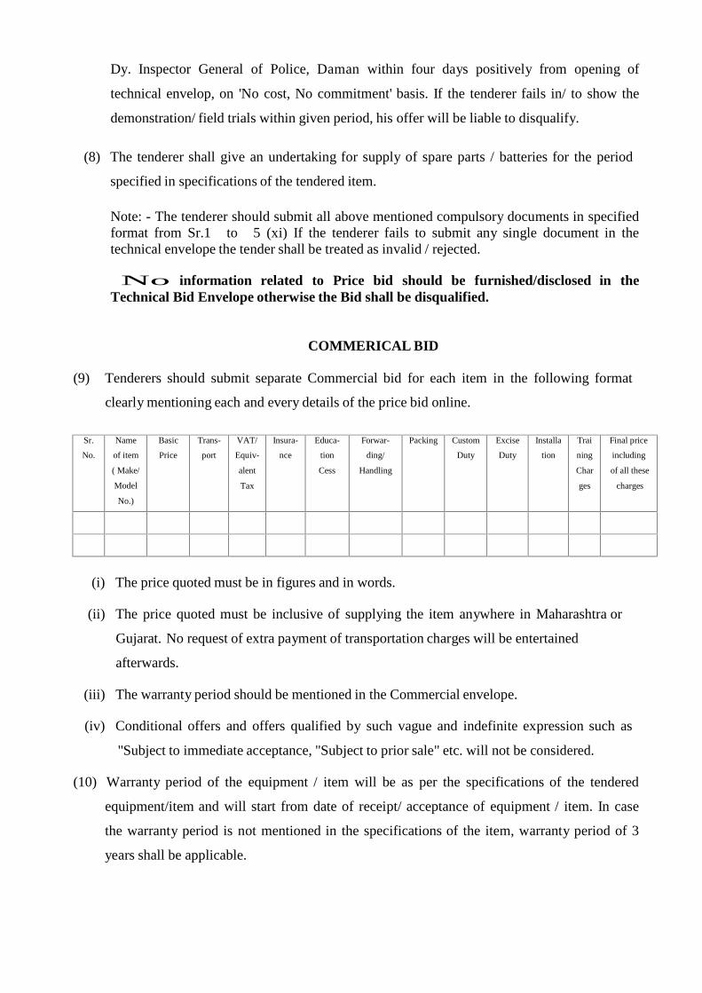
(9) Tenderers should submit separate Commercial bid for each item in the following format
clearly mentioning each and every details of the price bid online.
Sr.
No.
Name
of item
( Make/
Model
No.)
Basic
Price
Trans-
port
VAT/
Equiv-
alent
Tax
Insura-
nce
Educa-
tion
Cess
Forwar-
ding/
Handling
Packing Custom
Duty
Excise
Duty
Installa
tion
Trai
ning
Char
ges
Final price
including
of all these
charges
(i) The price quoted must be in figures and in words.
(ii) The price quoted must be inclusive of supplying the item anywhere in Maharashtra or
Gujarat. No request of extra payment of transportation charges will be entertained
afterwards.
(iii) The warranty period should be mentioned in the Commercial envelope.
(iv) Conditional offers and offers qualified by such vague and indefinite expression such as
"Subject to immediate acceptance, "Subject to prior sale" etc. will not be considered.
(10) Warranty period of the equipment / item will be as per the specifications of the tendered
equipment/item and will start from date of receipt/ acceptance of equipment / item. In case
the warranty period is not mentioned in the specifications of the item, warranty period of 3
years shall be applicable.

(11) Comprehensive and Non-comprehensive Annual Maintenance Contract (AMC) rates
(if applicable ) must be mentioned after lapse of warranty period in Commercial envelope.
(12) Quantity of tendered item may vary subject to the final availability of funds.
(13) The selected vendor should be in position to supply the equipment within sixty
days or earlier from the date of placing of technically clear order / custom duty
exemption certificate
/ license copy etc.
(14) The testing charges for Government approved laboratories, if any of the samples
tendered will have to be paid by the shortlisted Bidders after the shortlisting of
Technical Bids. The rates of testing charges are likely to vary & the tenderer will have
to pay the current charges before sending the samples for testing. The samples will not be
returned to the tenderer.
(15) Octroi Exemption Certificate, if required, will be provided from this office on
the requirement and intimation by the tenderer.
(16) The commercial envelopes of only those participants will be opened who have passed
in demonstration/ laboratory tests/ field trials.
(17) Though any vendor can participate in the tender, the Dy. Inspector General of Police,
Daman reserves the right to select the vendor who has a manufacturing facility, service
center or repair workshop in Maharashtra or Gujarat.
(18) Participant should have after sales and service facilities at major cities in
Maharashtra, Gujarat wherever applicable.
(19) The Dy. Inspector General of Police, Daman, reserves the right to inspect the
manufacturing unit where ever found necessary, while considering the tender.
(20) It is responsibility of the vender to take back Earnest Money Deposit (EMD)
after finalization of the tender. No interest will be paid at any cost on Earnest Money
Deposit.

(21) The Dy. Inspector General of Police, Daman, reserves the right to reject any part or the
whole tender, or all tenders without assigning any reason.
(22) The right to ignore any tender which fails to comply with the above instruction is reserved.
(23) Tenderers have liberty to remain present or to authorize their representative at the
opening of technical or commercial tender at the time and date specified. Dates quoted
for opening of technical and commercial tender are subject to changes in case there is
any holiday abruptly declared by the Government or under certain unavoidable
circumstances.
(24) The Dy. Inspector General of Police, Daman does not pledge himself to accept the
lowest or any tender and reserves to himself the right of accepting the whole or any
part of the tender or portion of the quantity offered against any item and tenderer should
supply the same at the rate quoted.
(25) In the event of the order being placed against any of the tenderers and if such tenderers
fails to supply any stores according to specifications or the terms and conditions of
Acceptance of Tender or fails to replace any stores rejected by the Dy. Inspector General
of Police, Daman. or by any person on his behalf within such time as may be stipulated,
the Dy. Inspector General of Police, Daman, reserves the right to purchase such stores
from any other sources and at such price as the Dy. Inspector General of Police, Daman
shall in his sole discretions thinks fit.
If action as stipulated above is taken
(i) The offer of the defaulting contractor will not be considered.
(ii) The defaulting contractor will be penalized to the extent of the differences in
the rates or 10% of the value of the earlier orders whichever is higher.
(iii) If the defaulting contractor fails to pay the penalty he will be permanently de-
listed from the list of approved contractors of the Dy. Inspector General of
Police, Daman and the registration deposit of the contractors will be forfeited to
Government .
(26) In case of no delivery and /or delayed delivery against an order placed after Acceptance
of Tender the Dy. Inspector General of Police, Daman reserves to himself the right to
impose such penalty in his sole discretion as he thinks fit.
(a) Successful Tenderer will be required to pay security deposit as fixed by the Dy.
Inspector General of Police, Daman and enter in to agreement for the performance
of the contract.
(b) Tenderers convicted or involved in any criminal offence shall be considered
ineligible for awarding contract.
(27) As soon as is apparent that contract dates cannot be adhered to, an application shall be
sent to the Dy. Inspector General of Police, Daman.
(28) Without prejudice to the foregoing rights, if such failure to delivery in stipulated time
as aforesaid shall have arisen from any cause, which the Dy. Inspector General of Police,
Daman may admit as a reasonable ground for an extension of the time (and his decision
shall be final), he may allow such additional time considering the circumstances of the
case, which are justified. However, the decision taken by the Dy. Inspector General of
Police, Daman will be final.
(29) Provided always that any failure or delay on the part of sub-contractors through
their employee shall not be admitted as a reasonable ground for any extension of time or
for exempting the tenderer from liability for any such loss or damage, as aforesaid and
provided further that no extension shall be allowed unless applied for and if shall, in the
opinion of the Dy. Inspector General of Police, Daman. (Which shall be final) have been
made and in his opinion, are justified.
(30) Any statutory increases or decreases as an Act of State or the Central Governmentrelating to Sales Tax and other taxes shall be to the account of the contractor.
(31) Tenderers should state the place of inspection of the stores offered, if the goods are
offered for inspection outside Maharashtra State, the tenderer will have to bear all
expenditure of inspection carried out by this office.

(32) Goods should be dispatched at carrier’s risk failing which they should be properly
covered by transit insurance with Govt.Insurance Fund, Mumbai – 400 032. However,
the supplier will be responsible till the entire Stores contracted for arrive in good
condition at destination.
(33) The tenderer should specifically mention whether they are licensed under Industries
Development and Regulation (IDR) ACT 1951 for the production of the item in
quotation and if not, how prescribed and from whom they proposed to procure the
material and what arrangements are proposed for assembly to supply.
I agree with all the above terms and conditions.
Sub Divisional Police OfficerPolice Head Quarter
Daman
Date and Place ( N a m e , Signature and Rubber seal of Bidder)
SPECIFICATION FOR BULLET PROOF JACKETS
DESIGN PARAMETERS FOR BP JACKETS
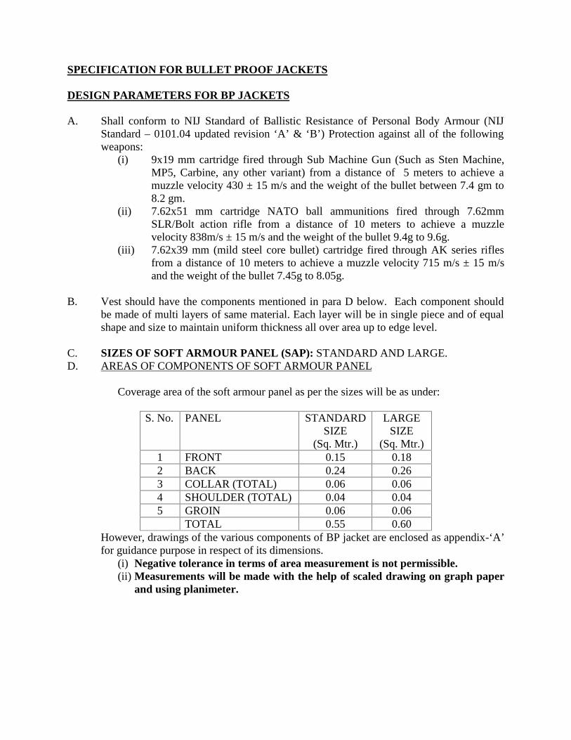
A. Shall conform to NIJ Standard of Ballistic Resistance of Personal Body Armour (NIJStandard – 0101.04 updated revision ‘A’ & ‘B’) Protection against all of the followingweapons:
(i) 9x19 mm cartridge fired through Sub Machine Gun (Such as Sten Machine,MP5, Carbine, any other variant) from a distance of 5 meters to achieve amuzzle velocity 430 ± 15 m/s and the weight of the bullet between 7.4 gm to8.2 gm.
(ii) 7.62x51 mm cartridge NATO ball ammunitions fired through 7.62mmSLR/Bolt action rifle from a distance of 10 meters to achieve a muzzlevelocity 838m/s ± 15 m/s and the weight of the bullet 9.4g to 9.6g.
(iii) 7.62x39 mm (mild steel core bullet) cartridge fired through AK series riflesfrom a distance of 10 meters to achieve a muzzle velocity 715 m/s ± 15 m/sand the weight of the bullet 7.45g to 8.05g.
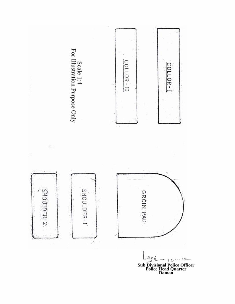
B. Vest should have the components mentioned in para D below. Each component shouldbe made of multi layers of same material. Each layer will be in single piece and of equalshape and size to maintain uniform thickness all over area up to edge level.
C. SIZES OF SOFT ARMOUR PANEL (SAP): STANDARD AND LARGE.D. AREAS OF COMPONENTS OF SOFT ARMOUR PANEL
Coverage area of the soft armour panel as per the sizes will be as under:
S. No. PANEL STANDARDSIZE
(Sq. Mtr.)
LARGESIZE
(Sq. Mtr.)1 FRONT 0.15 0.182 BACK 0.24 0.263 COLLAR (TOTAL) 0.06 0.064 SHOULDER (TOTAL) 0.04 0.045 GROIN 0.06 0.06
TOTAL 0.55 0.60However, drawings of the various components of BP jacket are enclosed as appendix-‘A’for guidance purpose in respect of its dimensions.
(i) Negative tolerance in terms of area measurement is not permissible.(ii) Measurements will be made with the help of scaled drawing on graph paper
and using planimeter.

E. WEIGHT OF THE JACKET
Total weight of BP Jacket including HAPs, SAPs, trauma pads and outer carriershould not exceed as mentioned below:-(i) Standard size - 6.31 kg(ii) Large size - 6.62 kg
F. Size of Hard Armour Panel –305mm X 254mmNegative tolerance in dimensions of HAP is not permissible.
G. Shall consist of an outer carrier, removable Soft Armour Panels (SAP) of aramidfiber/suitable material and Hard armour panel (HAP) made of High PerformancePolyethylene.
H. BP JACKET - CONSTRUCTION:(i) It should be in the form of jacket to provide protection against 9mm bullet (Threat
level IIIA of NIJ). It should not restrict overall vertical movement of the neck of thewearer.
(ii) It should have provision to accommodate two HAP plates in front and back as perdimensions specified in tender documents. Shall be lightweight and comfortableproviding optimum mobility and speed.
(iii)Adjustable at the shoulders, waist and groin with appropriate fasteners (Velcro’s). Anadjustable nylon belt of minimum 10 cm width should be provided with doublelocking of jacket with velcro.
(iv)The vendor has to declare the type of materials, number of layers and their aerialdensity in technical bid of tender and they have to maintain the same in bulk supply.
(v) SAP should be encased in polyurethane coated materials so as to make it water proof.
(vi) VELCRO FASTENERSAll the clothing flaps of the jackets should have high quality velcro fasteners, so thatit can be worn and taken off easily/quickly. The quality and report of Velcroincluding shears strength and peel strength should be as per Bureau of IndianStandards specification IS: 8156-1994. The IS: 8156-1994 may be available in theoffice of Bureau of Indian Standards. Vendors will submit test reports on Velcro fromany NABL accredited lab or DMSRD (MoD), Kanpur.
(vii) POCKET WITH FLAPSThe jacket should be provided with two external pockets in outer carrier to house twomagazines of 5.56mm LMG in each pocket. Two pockets should also be provided toaccommodate one grenade (HE 36) in each pocket. The size of each magazine is 19cm X 7.6cm X 3.5cm and size of HE 36 grenade is 110 mm X 65 mm.
(viii) BELT/KAMARBANDHAn additional belt of nylon/polyester weaving with minimum width of 10 cm shouldbe provided around the waist to properly secure the B.P. jackets with the body of thewearer around waist, so that weight of jacket is distributed on waist/shoulders.Kamarbandh should be of same material as outer carrier with velcro.

(ix) Two pouches (one each on front and rear of outer carrier) should be provided toaccommodate two 305 mm x 254 mm Hard Armour Plates so that jacket protects vitalorgans of body.
(x) Ballistic panels (SAPs & HAPs) shall be removable from outer carrier.(xi) Outer carrier shall be machine washable
(xii) TRAUMA PAD FOR TRAUMA ATTENUATION(a) Trauma pad must be provided behind the SAPs, so that it remains to body surface
to provide proper cushioning.(b) It must cover uniformly up to edge level of the SAPs.(c) Back face Signature (BFS) should not exceed 25 mm in plasticine block at 30±
2.9 degree centigrade temperature of plasticine.(d) Drop test will be carried out as per NIJ standards.
I. MATERIALS The outer carrier shall be made of high tenacity, heavy duty, aBPasion Proof and
100% vest integrity fabric PU coated Nylon. The Fabric weight should not be less than 95 gm/m2. The fabric shall be treated for protection against water, fire (fire retardant) and ultra
violet rays’ exposure. The fabric must be suitable to wear in the Indian conditions of heat, rain and
humidity. The inner side (body side) shall also be of a similar faBPic and shall be treated for
moisture and water repellency. The cloth of the carrier must be pre-shrunk before stitching. BP Jackets should be UV Proof.
Note:The methods of testing criteria for measuring the properties of outer carrier shall beas per IS: 11871-1986, IS: 3417-1979 (reaffirmed 1997), IS: 392-1989 and IS 391 –1975. Duration of flame after removal of burner-maximum 5 seconds (Test Method
IS11871) Duration of flame afterglow- maximum 5seconds (Test method IS11871) Hydrostatic Head-Minimum 100 cms of water (Test Method IS391-1975) Water penetration should be zero (Test Method IS392-1989) Mean Ultra Violet Penetration Factor- Minimum 100 (Test Method IS 3417) Important - Vendor should supply 3 meters of each faBPics used both at the time
of tender and from actual production for testing.
The tests specified will be conducted at a government institute, having required technicalexpertise. The institute will be selected by Technical Evaluation Committee inconsultation with experts. All tests will be in accordance with the SOP. Any changes inthe SOP will be decided by Technical Evaluation Committee.
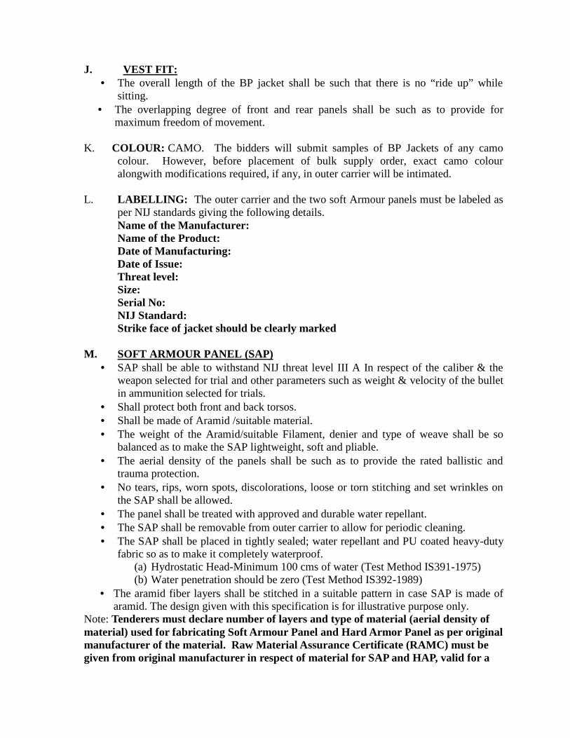
J. VEST FIT: The overall length of the BP jacket shall be such that there is no “ride up” while
sitting. The overlapping degree of front and rear panels shall be such as to provide for
maximum freedom of movement.
K. COLOUR: CAMO. The bidders will submit samples of BP Jackets of any camocolour. However, before placement of bulk supply order, exact camo colouralongwith modifications required, if any, in outer carrier will be intimated.
L. LABELLING: The outer carrier and the two soft Armour panels must be labeled asper NIJ standards giving the following details.Name of the Manufacturer:Name of the Product:Date of Manufacturing:Date of Issue:Threat level:Size:Serial No:NIJ Standard:Strike face of jacket should be clearly marked
M. SOFT ARMOUR PANEL (SAP) SAP shall be able to withstand NIJ threat level III A In respect of the caliber & the
weapon selected for trial and other parameters such as weight & velocity of the bulletin ammunition selected for trials.
Shall protect both front and back torsos. Shall be made of Aramid /suitable material. The weight of the Aramid/suitable Filament, denier and type of weave shall be so
balanced as to make the SAP lightweight, soft and pliable. The aerial density of the panels shall be such as to provide the rated ballistic and
trauma protection. No tears, rips, worn spots, discolorations, loose or torn stitching and set wrinkles on
the SAP shall be allowed. The panel shall be treated with approved and durable water repellant. The SAP shall be removable from outer carrier to allow for periodic cleaning. The SAP shall be placed in tightly sealed; water repellant and PU coated heavy-duty
fabric so as to make it completely waterproof.(a) Hydrostatic Head-Minimum 100 cms of water (Test Method IS391-1975)(b) Water penetration should be zero (Test Method IS392-1989)
The aramid fiber layers shall be stitched in a suitable pattern in case SAP is made ofaramid. The design given with this specification is for illustrative purpose only.
Note: Tenderers must declare number of layers and type of material (aerial density ofmaterial) used for fabricating Soft Armour Panel and Hard Armor Panel as per originalmanufacturer of the material. Raw Material Assurance Certificate (RAMC) must begiven from original manufacturer in respect of material for SAP and HAP, valid for a

period of six months from the closing date of tender. The vender has to declare thenumbers of layers used for fabricating SAP and HAP of tender samples and they haveto maintain the same in bulk supplies.N. HARD ARMOUR PLATE (HAP)
Shall be made of high performance polyethylene fiber. Shall provide NIJ threat level III protection against cartridge 7.62x51 mm
ammunition and 7.62x39 mm ammunition (mild steel core bullet) from a distanceof 10 meters in conjunction with Soft Armour Panel.
Each plate should not weigh more than 1.5 kg. Shall be of minimum size 305mm x 254mm to cover the vital parts of the body. Curvature of the HAP shall be suitable to fit the body contour. HAP shall be shielded water repellant and PU coated heavy-duty faBPic so as to
make it completely water proof.O. OTHER STIPULATIONS
JACKET STYLE : POLICESERVICEABILITY : 10 YEARS (HAP, SAP & trauma pad)
GUARANTEE : The Outer Carrier along with trauma padding shall beguaranteed for a period of 2 years against all manufacturing defects
TEMPERATURE : -500 C to +500C (Operating temperature)HUMIDITY : 95% at 400CSTORAGE : Normal Room Temp.
P. IMMUNITY LEVEL:(a) Hard Armour Plates: The HAPs are to be tested in conjunction with SAPs.
Six bullets NATO ball (9.4g to 9.6gms) fired from 7.62 MM SLR/bolt action riflefrom a distance of 10 meters at zero angle of incidence.
Six bullets (mild steel core), from 7.62 mm of AK rifle from a distance of 10 Mts.at zero angle of incidence on separate plates.
(b) Soft Armour Panels: Six shots fired through 9mm Sub Machine Gun (Such as Sten Machine, MP-5,Carbine, any other variant) from a distance 5 meters. with a muzzle velocity 430 ± 15m/s and the weight of the bullet between 7.4 gm to 8.2 gm as specified in standard.The velocities of bullets fired through weapons are given as follows:
ArmourType
TestBullet
Bulletweight
ReferenceVelocitym/s
Hits perArmor partat 0º angle ofincidence
BFS*DepthMaximum
ShotsperPanel
III A 9mmFMJ RN
7.4gmto 8.2
gm
430 ± 15 4+ 2 at 300
angle25 mm 6
III 7.62mmNATOFMJ
9.4 to9.6g
838 ± 15 6 25 mm 6
7.62mmmild steelcore
7.45gto
8.05g
715 ± 15 6 25 mm 6
BFS – Back Face Signature on Plasticine.

Selected weapon and lot of ammunition, for which reference velocity hasbeen once achieved, will remain the same throughout ballistic testing of alltender samples of various firms.
All tests will be in accordance with the SOP. Any changes in the SOP will be decidedby Technical Evaluation Committee.
Q. Testing Criteria(i) Scientific inspections/ballistic trial of these BP jackets will be conducted as NIJ
standard 0101-04 incorporating revision 'A'&'B' for BP jackets.(ii) Groin Pad will be tested ballistically with 9mm SMC. Three evenly spaced fair
hits at zero degree angle incidences shall be taken and BFS should not exceed25mm.
R. Miscellaneous.
(i) The supplier /manufacturer shall provide one number of BP jackets of the ordersize along with HAP at their cost from the lot of every 500 numbers but minimumfour numbers per lot of jackets for the purpose of the ballistic test/evaluation ofthe tendered specifications at the time of materializing the supply. These will beselected prior to dispatch at random in the factory premises.
(ii) While submitting the samples for tender, the supplier shall mention the exact areaof SAP and HAP and give the template of the jackets as per the area, so thatimport of raw materials of the BP jackets will be allowed accordingly.
(iii) Five tender samples are required for technical evaluation from a firm.(iv) Each model/BP and of BP jackets should be submitted against a separate tender
form.S. Testing facilities
Ballistic trials as per the QRs will be held at TBPL, Chandigarh or any other facility asdecided by Technical Evaluation Committee.
STANDARD OPERATING PROCEDURES (SOP) FOR TESTING OF LIGHT WEIGHTBULLET PROOF JACKET.
A. General Information:
1. Before commencement of ballistic trial vendors shall be briefed about test procedures.They will be asked to sign certain certificates (Annexure A). Tests will be conducted asper laid down procedure. No deviation shall be allowed.
2. The decision of Technical Evaluation Committee as appointed by the MHA will be finaland binding. The test results will be recorded on the same day and firms' signatory shallbe required to sign Compliance Test Report (CTR) Annexure-B1 & B2. No re-testing oftested samples on the firm’s request will be undertaken.
3. Test sequence will be decided through draw of lots.4. Fair and unfair shots will be given due weightage.5. Ballistic trial will be conducted firstly on wet samples for each weapon (AK-47 Rifle,
7.62mm SLR/bolt action rifle and 9 mm Sub Machine Gun (Such as Sten Machine, MP-5,Carbine, any other variants), followed by dry test.
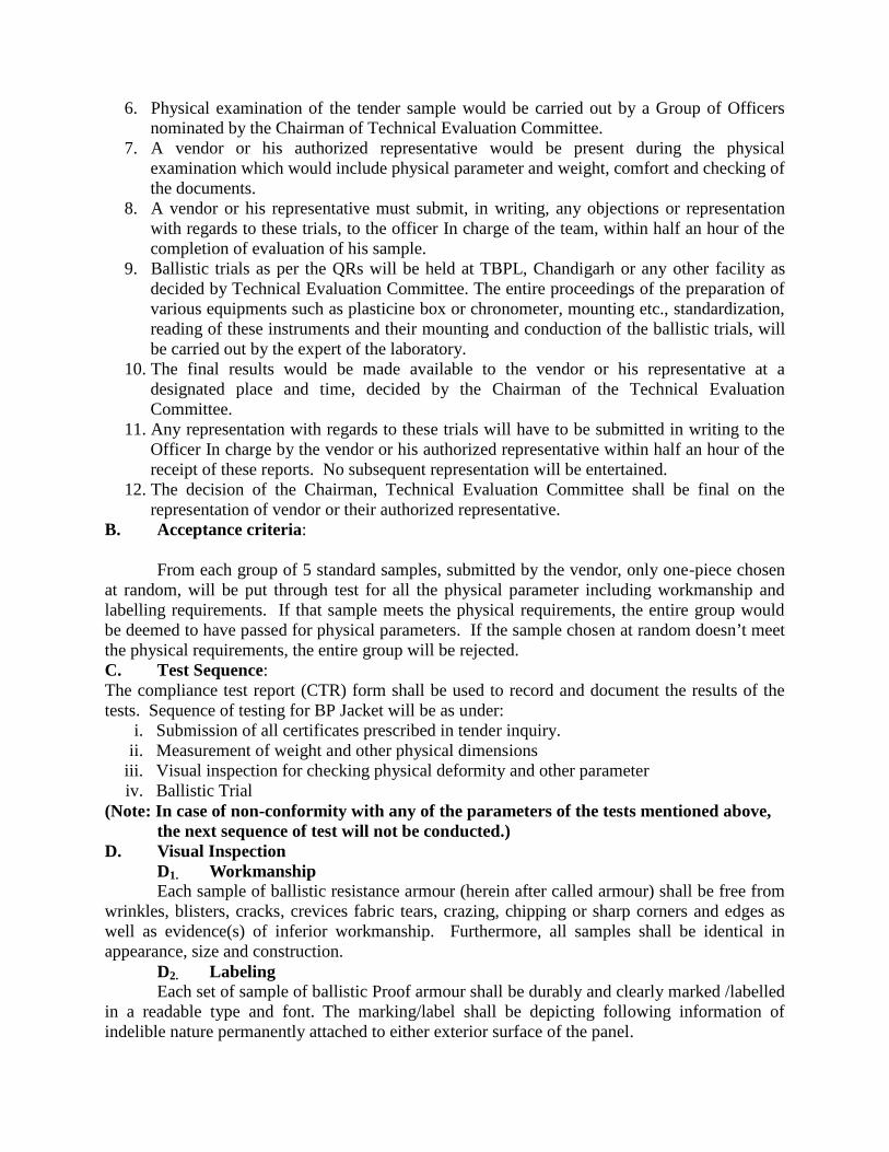
6. Physical examination of the tender sample would be carried out by a Group of Officersnominated by the Chairman of Technical Evaluation Committee.
7. A vendor or his authorized representative would be present during the physicalexamination which would include physical parameter and weight, comfort and checking ofthe documents.
8. A vendor or his representative must submit, in writing, any objections or representationwith regards to these trials, to the officer In charge of the team, within half an hour of thecompletion of evaluation of his sample.
9. Ballistic trials as per the QRs will be held at TBPL, Chandigarh or any other facility asdecided by Technical Evaluation Committee. The entire proceedings of the preparation ofvarious equipments such as plasticine box or chronometer, mounting etc., standardization,reading of these instruments and their mounting and conduction of the ballistic trials, willbe carried out by the expert of the laboratory.
10. The final results would be made available to the vendor or his representative at adesignated place and time, decided by the Chairman of the Technical EvaluationCommittee.
11. Any representation with regards to these trials will have to be submitted in writing to theOfficer In charge by the vendor or his authorized representative within half an hour of thereceipt of these reports. No subsequent representation will be entertained.
12. The decision of the Chairman, Technical Evaluation Committee shall be final on therepresentation of vendor or their authorized representative.
B. Acceptance criteria:
From each group of 5 standard samples, submitted by the vendor, only one-piece chosenat random, will be put through test for all the physical parameter including workmanship andlabelling requirements. If that sample meets the physical requirements, the entire group wouldbe deemed to have passed for physical parameters. If the sample chosen at random doesn’t meetthe physical requirements, the entire group will be rejected.C. Test Sequence:The compliance test report (CTR) form shall be used to record and document the results of thetests. Sequence of testing for BP Jacket will be as under:
i. Submission of all certificates prescribed in tender inquiry.ii. Measurement of weight and other physical dimensions
iii. Visual inspection for checking physical deformity and other parameteriv. Ballistic Trial
(Note: In case of non-conformity with any of the parameters of the tests mentioned above,the next sequence of test will not be conducted.)
D. Visual InspectionD1. WorkmanshipEach sample of ballistic resistance armour (herein after called armour) shall be free from
wrinkles, blisters, cracks, crevices fabric tears, crazing, chipping or sharp corners and edges aswell as evidence(s) of inferior workmanship. Furthermore, all samples shall be identical inappearance, size and construction.
D2. LabelingEach set of sample of ballistic Proof armour shall be durably and clearly marked /labelled
in a readable type and font. The marking/label shall be depicting following information ofindelible nature permanently attached to either exterior surface of the panel.
(a) Name of the manufacturer. XYZ(b) Name of the product. aabb(c) Date of manufacturing dd:mm:yyyy(d) Date of Issue (to be filled by user)(e) Protection level III/ IIIA(f) Size standard/ Large(g) Identification Number ABCD……(h) NIJ Standard 0101.04 (Revision A & B)
Note: Strike face of jacket should be clearly marked.
E. TEST METHODSE1. Workmanship Examination
a) Armour CarriersAll armour samples carriers and ballistic panel coverings received for compliance testing will bevisually and individually inspected for damage, material flaws, or poor workmanship as definedin specifications. All flaw(s) will be noted on the CTR form.
b) Ballistic PanelsPre-test:- Before testing, all armour samples ballistic panels and inserts received as
tender sample will be individually inspected for damage, material flaws, or poor workmanship asdefined in specifications. All identified flaws will be noted on the CTR form(s) for use indeficiency notification reporting.F. Conduct of Test –
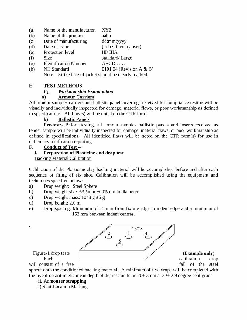
i. Preparation of Plasticine and drop testBacking Material Calibration
Calibration of the Plasticine clay backing material will be accomplished before and after eachsequence of firing of six shot. Calibration will be accomplished using the equipment andtechniques specified below:a) Drop weight: Steel Sphereb) Drop weight size: 63.5mm ±0.05mm in diameterc) Drop weight mass: 1043 g ±5 gd) Drop height: 2.0 me) Drop spacing: Minimum of 51 mm from fixture edge to indent edge and a minimum of
152 mm between indent centres.
.
Figure-1 drop tests (Example only)Each calibration drop
will consist of a free fall of the steelsphere onto the conditioned backing material. A minimum of five drops will be completed withthe five drop arithmetic mean depth of depression to be 20± 3mm at 30± 2.9 degree centigrade.
ii. Armourer strappinga) Shot Location Marking
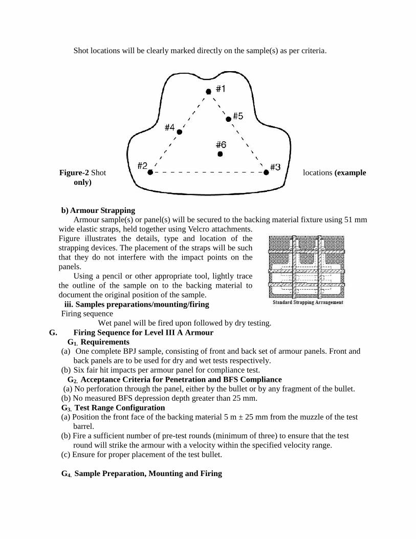
Shot locations will be clearly marked directly on the sample(s) as per criteria.
Figure-2 Shot locations (exampleonly)
b) Armour StrappingArmour sample(s) or panel(s) will be secured to the backing material fixture using 51 mm
wide elastic straps, held together using Velcro attachments.Figure illustrates the details, type and location of thestrapping devices. The placement of the straps will be suchthat they do not interfere with the impact points on thepanels.
Using a pencil or other appropriate tool, lightly tracethe outline of the sample on to the backing material todocument the original position of the sample.
iii. Samples preparations/mounting/firingFiring sequence
Wet panel will be fired upon followed by dry testing.G. Firing Sequence for Level III A Armour
G1. Requirements(a) One complete BPJ sample, consisting of front and back set of armour panels. Front and
back panels are to be used for dry and wet tests respectively.(b) Six fair hit impacts per armour panel for compliance test.
G2. Acceptance Criteria for Penetration and BFS Compliance(a) No perforation through the panel, either by the bullet or by any fragment of the bullet.
(b) No measured BFS depression depth greater than 25 mm.G3. Test Range Configuration(a) Position the front face of the backing material 5 m ± 25 mm from the muzzle of the test
barrel.(b) Fire a sufficient number of pre-test rounds (minimum of three) to ensure that the test
round will strike the armour with a velocity within the specified velocity range.(c) Ensure for proper placement of the test bullet.
G4. Sample Preparation, Mounting and Firing

i. Start with the wet conditioned back panel of armour sample. Place the exposed surface ofthe calibrated backing material in intimate contact with the back face of the armour panelunder test and restrict the movement of the panel from its original position by securing itwith two vertical and three horizontal elastic straps, 51 mm wide with Velcro closures. Usinga pencil or other appropriate tool, lightly trace the outline of the sample onto the backingmaterial to document the original position of the sample.
ii. The straps shall be positioned to restrict the movement of the panel from its originalposition, leaving the strike face impact area(s) exposed.
iii. Position the backing material fixture to assure proper impact placement and angle ofincidence (0 degree) of the test round at location one, as shown in figure 2.
iv. Measurement of Back Face Signature :-(a) Measure the BFS of first shot.(b) Measure the BFS of 2nd or 3rd shot (which is having higher velocity).(c) The maximum value of Back Face Signature (BSF) will be necessarily recorded
on Compliance Test Report (CTR) form between (a) and (b) which is havinghigher value.
v. Fire Shot No. 1: Fire the first test round against the armour panel at location one (fig. 2).Examine the armour panel and the backing material to determine whether the bullet made afair hit and whether complete penetration occurred. If no complete penetration (CP)occurred and the bullet made a fair hit, measure and record the BFS depression. Record theBFS on the CTR.
vi. If no complete penetration occurred and the bullet made an unfair hit, a second attempt willbe made to attain a fair hit. This second attempt will be made to impact the same generalarea of the panel as the first shot but more than 51 mm from the previous shot and morethan 51 mm from any edge of the panel. If a fair hit is still not attained, the firingsequence will be terminated. No more than a total of eight impacts are permitted onany armour panel.
vii. Remount Armour Sample: Adjust the armour panel back to its original condition (i.e.smooth and manipulate the ballistic material to return it to its original configuration) andreplace it on the backing material in its original position using the traced outline in thebacking material as a guide. Do not recondition the backing material; do not remove thetest bullet if it is trapped in the panel. When conducting the remaining firing sequence,inspect the armour panel following each impact to verify that the impact was a fair hit withno complete penetration, and smooth out the panel in preparation for the next shot.
viii. Fire Shot No. 2: Reposition the backing material fixture with the armour panel in positionso that the shot will impact the panel at location two. Fire the test round. Do not change theposition of the armour panel on the backing material, but adjust the panel and mountingstraps as necessary to restore its original condition. Do not remove any trapped bulletsfrom the panel.
ix. Fire Shot No. 3: Reposition the backing material fixture with the armour panel in positionso that the shot will impact the panel at location three. Fire the test round. Do not change theposition of the armour panel on the backing material, but adjust the panel and mountingstraps as necessary to restore its original condition. Do not remove any trapped bulletsfrom the panel.
x. Fire Shot No. 4: Reposition the backing material fixture with the armour panel in positionso that the shot will impact the panel at location four. Fire the test round. Do not change the

position of the armour panel on the backing material, but adjust the panel and mountingstraps as necessary to restore its original condition. Do not remove any trapped bulletsfrom the panel.
xi. Fire Shot No. 5: Reposition the backing material fixture with the armour panel in positionso that the shot will impact the panel at location five. Fire the test round. Do not change theposition of the armour panel on the backing material, but adjust the panel and mountingstraps as necessary to restore its original condition. Do not remove any trapped bulletsfrom the panel.
xii. Fire Shot No. 6: Reposition the backing material fixture with the armour panel in positionso that the defined angle of incidence between the perpendicular to the armour and the lineof flight of the test round is 0 degree and the bullet will impact the armour at location six.Fire the test round. Remove and thoroughly examine the armour panel and backingmaterial for complete penetrations by bullets or fragments.
xiii. Post Test Drop Calibration: Perform five drop tests on the backing material in the generalareas of figure 1. Post test drop locations shall be at least 51 mm away from any other dropimpact. Record all measurements on the CTR and determine compliance with dropcalibration criteria. If the backing material meets post test drop specifications, repair thebacking material and repeat the pre-test drop calibration. If the repaired backing materialfixture passes the pre-test calibration, it may be reused for the second panel firing sequence,subject to passing another post test drop upon conclusion of the firings.
xiv. Test Front Panel: Mount the front panel of the armour sample to a pre-test drop calibratedbacking material fixture, and repeat the test sequence above using the same ammunition.Record all results on the CTR.
xv. Record Results: Record the results of all testing in the CTR (appendix-B2).
H. P-BFS Test for Groin PadGroin pad shall be impacted with three fair hits evenly spaced not less than 51 mm apart,
and not less than 51mm from an edge, at 0 degree obliquity. The BFS due to the first fair hitshall be measured to determine compliance. Any fair hit bullet that penetrates the groinpad, the complete jacket shall be rejected.
I. Firing Sequence for Level III ArmourI1. Requirements
(a) Two complete BPJ sample or two each- front and back SAP and four HAP.(b) Front panel with plate and back with plate will be put to dry and wet tests respectively.(c) Six fair hit impacts against each of front and back SAP and HAP combine.I2. Acceptance Criteria for Penetration and BFS Compliance(a) No perforation either by the bullet or any fragment of the bullet through the armour (SAP
and HAP combine).(b) No measured BFS depression depth greater than 25 mm.I3. Test Range Configuration
(a) Position the front face of the backing material 10m±25 mm from the muzzle of the testbarrel.
(b) Fire a sufficient number of pre-test rounds (minimum of three) to ensure that theammunition will strike the armour with a velocity within the specified velocity range.
(c) Ensure for proper placement of the test bullet.

I4. Sample Preparation, Mounting, and Firingi. For armour that utilizes a rigid plate or plates such that the armour panel does not make full
contact with the backing material surface, the backing material will be built up in a mannerthat conforms to the armour panel's shape. This build up will require use of additional claybacking material conditioned in the same manner as the backing material fixture.
ii. Mark the front armour panel, plate for six impacts, evenly spaced on the panel according tothe spacing criteria of a minimum of 51 mm from any edge to armour and 51 mm from anyprevious impact. Start with Wet conditioned back armour panel and plate.
iii. Place the exposed surface of the conditioned and drop test caliBPated backing material inintimate contact with the back face of the armour panel, plate and secure it with twovertical and three horizontal elastic straps, 51 mm wide with Velcro closures.
iv. The straps shall be positioned to leave the strike face impact areas exposed while notpermitting the armour to shift on the backing material when impacted.
v. Firing Sequence: Conduct all six of the firings in accordance with the sequence specified infigure 3 below. All shots for Type III armour samples will be at zero degree obliquity.
vi. Front Panel Testing: Repeat the above tests on dry front ballistic panel and plate combine.vii. Record Test Results: Record the result of all testing in the CTR (appendix-B2).
Figure-3 (Example only)viii. Measurement of Back Face Signature (BFS):-
(a) Measure the BFS of all shots.(b) The highest value of Back Face Signature (BSF) will be recorded on Compliance
Test Report (CTR) form.
J4. Sample Preparation, Mounting, and Firingi. For armour that utilizes a rigid plate or plates such that the armour panel does not make full
contact with the backing material surface, the backing material will be built up in a mannerthat conforms to the armour panel's shape. This build up will require use of additional claybacking material conditioned in the same manner as the backing material fixture.
ii. Mark centrally the plate for an impact according to the spacing criteria of a minimum of51 mm from any edge of armour. Start with wet conditioned and followed by dry.
iii. Place the exposed surface of the conditioned and drop test calibrated backing material inintimate contact with the back face of the armour panel, plate and secure it with twovertical and three horizontal elastic straps, 51 mm wide with Velcro closures.
iv. The straps shall be positioned to leave the strike face impact areas exposed while notpermitting the armour to shift on the backing material when impacted.
v. Firing Sequence: Conduct a test shot centrally on HAP with zero degree obliquity.vi. Front Panel Testing: Repeat the above tests on dry front SAP and HAP combine.vii. Record Test Results: Record the result of all testing in the CTR (appendix-B2).
K. Fair Hit:A bullet that impacts the armour sample or panel at an angle of incidence no greater than
±5° from the intended angle of incidence, no closer to the edge of the ballistic panel than 51 mmand no closer to a prior hit than 51 mm at an impact velocity within ±15 m/s of the requiredreference test velocity.
A bullet that impacts the sample of panel at an angle of incidence no greater than ±5°from the intended angle of incidence, no closer to the edge of the ballistic panel than 51 mm andno closer to a prior hit than 51 mm at an impact velocity less than 15 m/s below the requiredreference test velocity which produces a penetration or an excessive back face signature.
A bullet that impacts the armour sample or panel at an angle of incidence no greater than±5° from the intended, no closer to the edge of the ballistic panel than 51 mm and no closer to aprior hit than 51 mm at an impact velocity more than 15 m/s above the required test velocitywhich does not produces a penetration or an excessive back face signature.Note: Selected weapon and lot of ammunition for which reference velocity has been once
established, will be deemed standardised throughout the ballistic testing for all thesubsequent tests of all tenderers.
L. Post test: - each armour samples ballistic components (e.g., front and back panels) will bephysically inspected immediately after testing and their respective configuration reported forlayer, weave, stitching, material, etc.
(a) Label Examination:The complete armour sample and each part (carrier and ballistic panels) will be examined
for conformance to the labelling requirements of specifications. Note any deviations fromrequirements will be recorded in the CTR form.
(b) Inspection Deficiency NotificationsThe MHA/Competent Authority will be informed within two (2) working days of
discovery of any shipping damage, major product flaws, or poor quality workmanship, or labelinconsistency. Such discoveries and notice will result in suspension of the compliance test untilapproval of MHA/ Competent Authority is received by the testing Committee to further proceedwith the tests/ evaluation.M. Sampling:
Out of five tender samples, one will be used for physical dimension measurement andfrom remaining four samples; for every ballistic test one will be selected randomly.
N. Ballistic Penetration and Back face Signature Test (P-BFS):i. All armour samples submitted to compliance testing will undergo a series of ballistic
impact tests using the ammunition specified in specifications. Depth of back facesignature will be measured by using callipers after removing the deformation in the claywith the help of metal scrappers. A measurement of 25 mm or less is a passing test.
ii. Average of two reading by placing measuring instrument putting horizontally acrossthe back face material will be recorded in CTR.

O. Velocity Measurement Equipment (Example only)Test round velocities will be determined using a velocity measurement equipment.
P. Wet ConditioningBody armour undergoing P-BFS performance testing will be tested in a wet condition.
Dipping armour panel under test for thirty minutes in a large vessel where vertical column ofwater is minimum 15 centimetres will produce this condition.Q. Test Duration
After wet conditioning the first shot must be fired within ten minute and entire shots firedwithin 30 minutes. Test start and stop times will be recorded in the CTR form.R. Backing Material Fixture Preparation
a) Backing Material Fixtures
A minimum of three backing material fixtures filled with appropriate backing material isrequired. The inside dimensions of the backing material fixture shall be 610 mm x 610 mm x 140mm ± 2 mm deep. The tolerance on all dimensions will be ± 2 mm.
b) Surface Preparation
The clay in each BMF will be manipulated to produce a block free of voids, and with asmooth, flat front surface for the accurate and consistent measurement of depression depths. Thefront surface of the backing material shall be even with the surface plane defined by the fixtureedges. Additional clay, conditioned along with each BMF, shall be used to fill voids and restorethe front surface as needed.
c) Backing Material Conditioning
The clay of backing material shall be initially conditioned at a temperature of 302.9degree centigrade. The actual conditioning temperature and recovery time between uses will bedetermined by drop test results. The failure to meet drop test result will require reconditioning ofback face material.

d) Backing Material Fixture Rotation:
In case back face material is not giving prescribed drop test result, then it should bereplaced with newly conditioned material. All drop test calibration results will be recorded in theCTR. It is recommended that a minimum of two fixtures be rotated between the test andconditioning cycles to ensure fulfilment of these requirements.
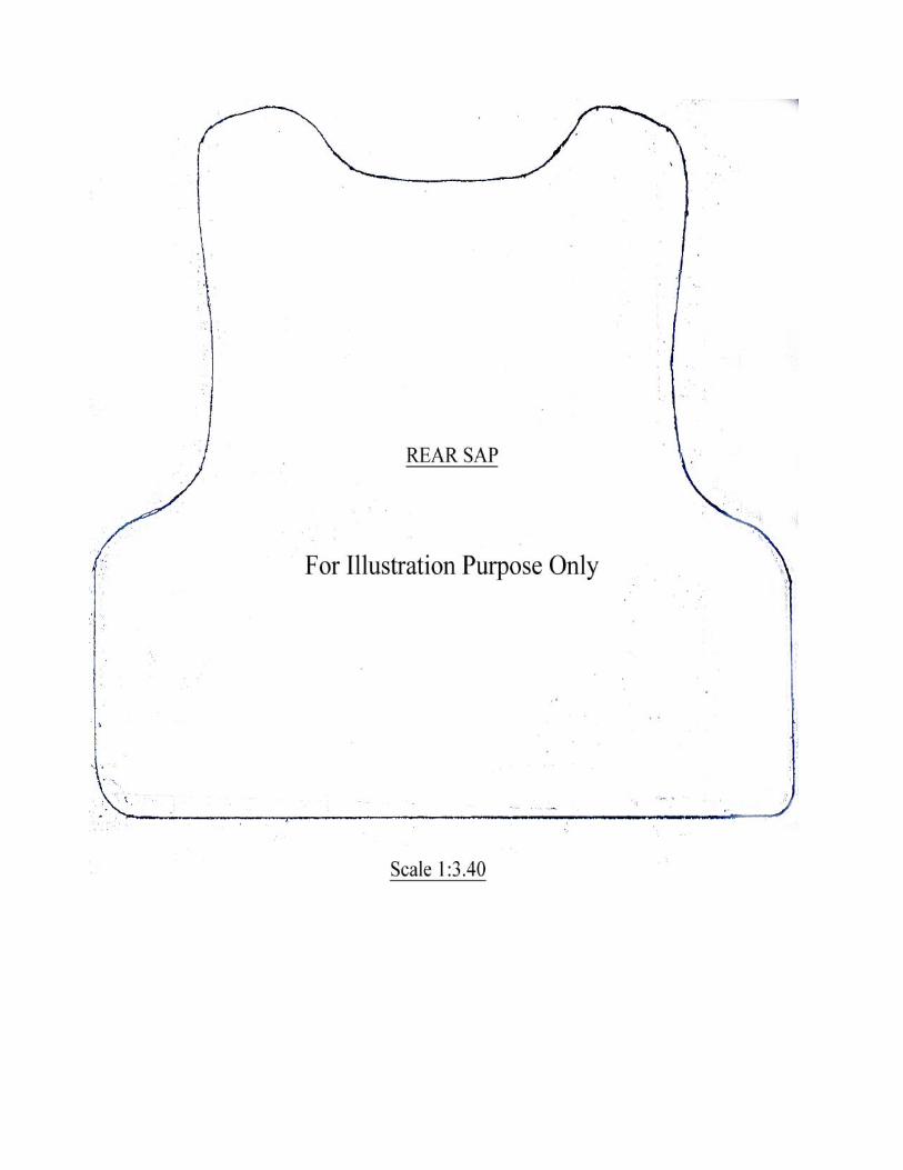
For illustration purpose only
FRONT SAP
Scale 1:2.77
Sub Divisional Police OfficerPolice Head Quarter
Daman


