Serial Communication Expansion...
58
Serial Communication Expansion Boards Catalog No. EXB001A01 Catalog No. EXB002A01 Catalog No. EXB012A01 Installation and Operating Manual 4/03 MN1310
-
Upload
hoanghuong -
Category
Documents
-
view
223 -
download
1
Transcript of Serial Communication Expansion...

Serial CommunicationExpansion Boards
Catalog No. EXB001A01Catalog No. EXB002A01Catalog No. EXB012A01
Installation and Operating Manual
4/03 MN1310

Table of Contents
Table of Contents i
Section 1General Information 1-1. . . . . . . . . . . . . . . . . . . . . . . . . . . . . . . . . . .
Introduction 1-1. . . . . . . . . . . . . . . . . . . . . . . . . . . . . . . . . . . . . . . . . Limited Warranty 1-2. . . . . . . . . . . . . . . . . . . . . . . . . . . . . . . . . . . . . Safety Notice 1-3. . . . . . . . . . . . . . . . . . . . . . . . . . . . . . . . . . . . . . . .
Precautions 1-3. . . . . . . . . . . . . . . . . . . . . . . . . . . . . . . . . . . . . . . Section 2Expansion Board Description 2-1. . . . . . . . . . . . . . . . . . . . . . . . . .
Introduction 2-1. . . . . . . . . . . . . . . . . . . . . . . . . . . . . . . . . . . . . . . . . Section 3Installation 3-1. . . . . . . . . . . . . . . . . . . . . . . . . . . . . . . . . . . . . . . . . . . .
Board Installation 3-1. . . . . . . . . . . . . . . . . . . . . . . . . . . . . . . . . . . . AC Controls 3-2. . . . . . . . . . . . . . . . . . . . . . . . . . . . . . . . . . . . . . . . .
Single Expansion Board Installation 3-2. . . . . . . . . . . . . . . . . . Dual Expansion Board Installation 3-4. . . . . . . . . . . . . . . . . . .
SCR DC Controls 3-6. . . . . . . . . . . . . . . . . . . . . . . . . . . . . . . . . . . . Single Expansion Board Installation 3-6. . . . . . . . . . . . . . . . . . Dual Expansion Board Installation 3-7. . . . . . . . . . . . . . . . . . .
Section 4Hardware Setup 4-1. . . . . . . . . . . . . . . . . . . . . . . . . . . . . . . . . . . . . . .
Termination 4-1. . . . . . . . . . . . . . . . . . . . . . . . . . . . . . . . . . . . . . . . . EXB001A01 Setup 4-2. . . . . . . . . . . . . . . . . . . . . . . . . . . . . . . . . . .
DIP Switch Settings 4-2. . . . . . . . . . . . . . . . . . . . . . . . . . . . . . . . Jumper Setting 4-2. . . . . . . . . . . . . . . . . . . . . . . . . . . . . . . . . . . . Cable Connection 4-2. . . . . . . . . . . . . . . . . . . . . . . . . . . . . . . . .
EXB002A01 Setup 4-4. . . . . . . . . . . . . . . . . . . . . . . . . . . . . . . . . . . DIP Switch Settings 4-4. . . . . . . . . . . . . . . . . . . . . . . . . . . . . . . . Jumper Setting 4-4. . . . . . . . . . . . . . . . . . . . . . . . . . . . . . . . . . . . Cable Connection 4-4. . . . . . . . . . . . . . . . . . . . . . . . . . . . . . . . .
EXB012A01 Setup 4-7. . . . . . . . . . . . . . . . . . . . . . . . . . . . . . . . . . . DIP Switch Settings 4-7. . . . . . . . . . . . . . . . . . . . . . . . . . . . . . . . Jumper Settings 4-7. . . . . . . . . . . . . . . . . . . . . . . . . . . . . . . . . . . Cable Connection 4-7. . . . . . . . . . . . . . . . . . . . . . . . . . . . . . . . .
Control Terminal Strip Connections 4-14. . . . . . . . . . . . . . . . . . . . .

ii Table of Contents
Section 5Software Setup 5-1. . . . . . . . . . . . . . . . . . . . . . . . . . . . . . . . . . . . . . . .
Configure Control Software for Serial Operating Mode 5-1. . . . Host Computer Setup 5-3. . . . . . . . . . . . . . . . . . . . . . . . . . . . . . . . .
Setup Windows 3.1 Terminal Emulation 5-3. . . . . . . . . . . . . . . Serial Mode Control Setup 5-5. . . . . . . . . . . . . . . . . . . . . . . . . .
Section 6Serial Command Language 6-1. . . . . . . . . . . . . . . . . . . . . . . . . . . .
ACK_ON 6-1. . . . . . . . . . . . . . . . . . . . . . . . . . . . . . . . . . . . . . . . . ACK_OFF 6-1. . . . . . . . . . . . . . . . . . . . . . . . . . . . . . . . . . . . . . . . Ax(Address) 6-1. . . . . . . . . . . . . . . . . . . . . . . . . . . . . . . . . . . . . . AA(Address All) 6-2. . . . . . . . . . . . . . . . . . . . . . . . . . . . . . . . . . . AUn (Auto-Tune) 6-2. . . . . . . . . . . . . . . . . . . . . . . . . . . . . . . . . . C (Clear) 6-2. . . . . . . . . . . . . . . . . . . . . . . . . . . . . . . . . . . . . . . . . CALC 6-2. . . . . . . . . . . . . . . . . . . . . . . . . . . . . . . . . . . . . . . . . . . . D (Disable) 6-3. . . . . . . . . . . . . . . . . . . . . . . . . . . . . . . . . . . . . . . DL (Download) 6-3. . . . . . . . . . . . . . . . . . . . . . . . . . . . . . . . . . . . E (Enable) 6-3. . . . . . . . . . . . . . . . . . . . . . . . . . . . . . . . . . . . . . . . ECHO_ON 6-3. . . . . . . . . . . . . . . . . . . . . . . . . . . . . . . . . . . . . . . . ECHO_OFF 6-3. . . . . . . . . . . . . . . . . . . . . . . . . . . . . . . . . . . . . . . F (Fault) 6-4. . . . . . . . . . . . . . . . . . . . . . . . . . . . . . . . . . . . . . . . . . GO (Process Target Register Command) 6-4. . . . . . . . . . . . . H (Home) 6-4. . . . . . . . . . . . . . . . . . . . . . . . . . . . . . . . . . . . . . . . . HF (Help Fault) 6-4. . . . . . . . . . . . . . . . . . . . . . . . . . . . . . . . . . . . HL (Help Log) 6-5. . . . . . . . . . . . . . . . . . . . . . . . . . . . . . . . . . . . . HP or HPxxxx or HPxxxx nnnn (Help Parameters) 6-5. . . . . . ID (Power Base ID) 6-5. . . . . . . . . . . . . . . . . . . . . . . . . . . . . . . . IO (IO Status) 6-6. . . . . . . . . . . . . . . . . . . . . . . . . . . . . . . . . . . . . Jx (Jog) 6-6. . . . . . . . . . . . . . . . . . . . . . . . . . . . . . . . . . . . . . . . . . L (Log) 6-6. . . . . . . . . . . . . . . . . . . . . . . . . . . . . . . . . . . . . . . . . . . M or Mxxxx (Absolute Move) 6-6. . . . . . . . . . . . . . . . . . . . . . . . m or mxxxxx (Incremental Move) 6-7. . . . . . . . . . . . . . . . . . . . . NULL 6-7. . . . . . . . . . . . . . . . . . . . . . . . . . . . . . . . . . . . . . . . . . . . Ox (Report) 6-7. . . . . . . . . . . . . . . . . . . . . . . . . . . . . . . . . . . . . . . P or Pxxxx or Pxxxx nnnn 6-8. . . . . . . . . . . . . . . . . . . . . . . . . . . S (STOP) 6-9. . . . . . . . . . . . . . . . . . . . . . . . . . . . . . . . . . . . . . . . . SCxxxx (Security Code) 6-9. . . . . . . . . . . . . . . . . . . . . . . . . . . .
Table of Contents iii
ST (STATUS) 6-9. . . . . . . . . . . . . . . . . . . . . . . . . . . . . . . . . . . . . STATUS (FULL STATUS) 6-9. . . . . . . . . . . . . . . . . . . . . . . . . . . T or Tnnnn (Torque command) 6-10. . . . . . . . . . . . . . . . . . . . . . TAR xxxx (Target Register) 6-10. . . . . . . . . . . . . . . . . . . . . . . . . . TP (Test Points) 6-11. . . . . . . . . . . . . . . . . . . . . . . . . . . . . . . . . . . TPF (Test Point File) 6-11. . . . . . . . . . . . . . . . . . . . . . . . . . . . . . . TPT (Test Point Trigger) 6-11. . . . . . . . . . . . . . . . . . . . . . . . . . . . UL (Upload) 6-11. . . . . . . . . . . . . . . . . . . . . . . . . . . . . . . . . . . . . . . V or Vnnnn (Velocity Command) 6-12. . . . . . . . . . . . . . . . . . . . . VX or VXnnn (Velocity Command/256) 6-12. . . . . . . . . . . . . . . . v or vxxxx (Positioning Speed) 6-12. . . . . . . . . . . . . . . . . . . . . . . W (Position to Zero) 6-12. . . . . . . . . . . . . . . . . . . . . . . . . . . . . . . . Z (Set Current Position to Zero) 6-12. . . . . . . . . . . . . . . . . . . . . .
Section 7Communication Using a Modem 7-1. . . . . . . . . . . . . . . . . . . . . . . .
Series H Controls Remote Modem Setup 7-1. . . . . . . . . . . . . . . . Set Modem Switches 7-1. . . . . . . . . . . . . . . . . . . . . . . . . . . . . . .

iv Table of Contents

Section 1General Information
General Information 1-1
IntroductionThe Baldor controls represent the latest technology in microprocessorbased motor controls. In addition to the user programmable parametersavailable in every control, many different expansion boards are availablefrom Baldor to further customize the control to most any application.Expansion boards are categorized by compatibility into two groups:Group 1 and Group 2, see Table 1-1. A board from either group may beused alone in a control. If two boards are to be used, one board mustbe from Group 1 and the other from Group 2.Note: Using two Group 1 or two Group 2 boards in the same control is
not allowed.Table 1-1 Group 1 and Group 2 Board Categories
No Group 1 or 2 Connectors Catalog No. Manual No.Isolated I/O Relay Accessory Board ACB003A0X MN1325
Group 1 Board Name Catalog No. Manual No.Isolated Input EXB003A0X MN1314Master Pulse Reference/ Isolated Pulse Follower
EXB005A0X MN1312
DC Tachometer Interface EXB006A0X MN1311Isolated Encoder EXB008A0X MN1317Resolver to Digital Interface EXB009A0X MN1313Group 2 Board NameRS-232 Serial EXB001A0X MN1310RS-422/RS-485 Serial EXB002A0X MN1310RS-232/485 Serial EXB012A0X MN1310Four Output Relays/3-15 PSI Pneumatic
EXB004A0X MN1315
High Resolution Analog I/O EXB007A0X MN13162 Isolated Analog Output/ 3 RelayOutput
EXB010A0X MN1319
Device Net EXB013A0X MN1320Modbus Plus EXB015A0X MN1322Profibus DP EXB014A0X MN1323

1-2 General Information
Limited Warranty
For a period of two (2) years from the date of original purchase,BALDOR will repair or replace without charge controls andaccessories which our examination proves to be defective inmaterial or workmanship. This warranty is valid if the unit has notbeen tampered with by unauthorized persons, misused, abused, orimproperly installed and has been used in accordance with theinstructions and/or ratings supplied. This warranty is in lieu of anyother warranty or guarantee expressed or implied. BALDOR shallnot be held responsible for any expense (including installation andremoval), inconvenience, or consequential damage, includinginjury to any person or property caused by items of our manufactureor sale. (Some states do not allow exclusion or limitation ofincidental or consequential damages, so the above exclusion maynot apply.) In any event, BALDOR’s total liability, under allcircumstances, shall not exceed the full purchase price of thecontrol. Claims for purchase price refunds, repairs, orreplacements must be referred to BALDOR with all pertinent dataas to the defect, the date purchased, the task performed by thecontrol, and the problem encountered. No liability is assumed forexpendable items such as fuses.
Goods may be returned only with written notification including aBALDOR Return Authorization Number and any return shipmentsmust be prepaid.

General Information 1-3
Safety NoticeThis equipment contains voltages that may be as great as 1000 volts!Electrical shock can cause serious or fatal injury. Only qualifiedpersonnel should attempt the start-up procedure or troubleshoot thisequipment.This equipment may be connected to other machines that have rotatingparts or parts that are driven by this equipment. Improper use cancause serious or fatal injury. Only qualified personnel should attemptthe start-up procedure or troubleshoot this equipment.
PRECAUTIONS
WARNING: Do not touch any circuit board, power device orelectrical connection before you first ensure that power hasbeen disconnected and there is no high voltage presentfrom this equipment or other equipment to which it isconnected. Electrical shock can cause serious or fatalinjury. Only qualified personnel should attempt the start-upprocedure or troubleshoot this equipment.
WARNING: Be sure that you are completely familiar with thesafe operation of this equipment. This equipment may beconnected to other machines that have rotating parts orparts that are controlled by this equipment. Improper usecan cause serious or fatal injury. Only qualified personnelshould attempt the start-up procedure or troubleshoot thisequipment.

1-4 General Information
WARNING: Be sure the system is properly grounded beforeapplying power. Do not apply AC power before you ensurethat all grounding instructions have been followed.Electrical shock can cause serious or fatal injury.
WARNING: Do not remove cover for at least five (5) minutesafter AC power is disconnected to allow capacitors todischarge. Dangerous voltages are present inside theequipment. Electrical shock can cause serious or fatalinjury.
WARNING: Improper operation of control may cause violentmotion of the motor shaft and driven equipment. Be certainthat unexpected motor shaft movement will not cause injuryto personnel or damage to equipment. Peak torque ofseveral times the rated motor torque can occur duringcontrol failure.
WARNING: Motor circuit may have high voltage presentwhenever AC power is applied, even when motor is notrotating. Electrical shock can cause serious or fatal injury.
Caution: To prevent equipment damage, be certain that theelectrical service is not capable of delivering more than themaximum line short circuit current amperes listed in theappropriate control manual, 230 VAC, 460 VAC or 575 VACmaximum per control rating.

Section 2Expansion Board Description
Description 2-1
IntroductionAny computer that provides an RS–232, RS–422, RS–485 serialinterface may be used to setup and operate the control using one of theavailable serial communication expansion boards. A proprietary SerialCommand Language is built into the control for this purpose. Acomputer or terminal capable of serial communications using thestandard ASCII character set is required to use the Serial CommandLanguage. A typical system consists of an MS–DOS compatiblecomputer running communications software. The Serial CommandLanguage can control any aspect of the control including running themotor, changing parameters, and viewing output conditions. Somecontrol features are unique to the Serial Operating Mode, such aspositioning and file transfer commands. Note that the SerialCommunication Expansion Boards can be used with controls inoperating modes other than SERIAL to change parameters and viewoutput conditions. When used in operating modes other than Serial, thedrive will not accept commands from the Host Computer.RS-232 Serial Communications Expansion Board
Catalog No. EXB001A01RS-422/485 Serial Communications Expansion Board
Catalog No. EXB002A01RS-232/485 Serial Communications Expansion Board
Catalog No. EXB012A01 – Not compatible with 19H and 20H

2-2 Description

Section 3Installation
Installation 3-1
Board InstallationThis section describes the Expansion Board installation procedure.
Caution: Before you proceed, be sure to read and becomefamiliar with the safety precautions at the beginning of thismanual. Do not proceed if you are unsure of the safetyprecautions described. If you have any questions, contactBALDOR before you proceed.
1. Remove the expansion board from the shipping container.2. Remove all packing material from the board.
Caution: Be sure all packing materials are removed from theboard. Conductive foam may be present on the connectorsto prevent static build up during shipping. This can preventproper circuit operation.
If you are installing only one board, refer to the “Single Expansion BoardInstallation” procedure. If you are installing two expansion boards (or asecond board) refer to the “Dual Expansion Board Installation”procedure.

3-2 Installation
AC Controls(For all 15H Inverter, 21H Line Regen Inverter, 18H Vector, 22H LineRegen Vector and 23H Servo).Single Expansion Board InstallationProcedure:1. Be sure drive operation is terminated and secured.2. Remove all power sources from the control.3. Wait at least 5 minutes for internal capacitors to discharge.4. Remove the four (4) Phillips head screws (1/4 turn) that secure the
control cover. (For A & B size, remove four screws that secure thecover. On floor mounted G size enclosures, open the enclosuredoor).
5. Remove the control cover.6. Slide the expansion board male connector into the female
connector of the control board. See Figure 3-1.7. Securely mount the expansion board to the sheet metal mounting
plate using the #6 screws provided in the installation hardware.See Figure 3-2.
8. The mechanical installation of the expansion board is nowcomplete. Refer to Section 4 of this manual and configure thejumpers as desired. Also complete the wiring before you proceedto step 9.
9. When complete, install the control cover using the four (4) Phillipshead screws (1/4 turn). (For A & B size, install four screws thatsecure the cover. On floor mounted G size enclosures, close theenclosure door).
10. Restore all power sources to the control.11. Restore drive operation.

Installation 3-3
AC ControlsSingle Expansion Board Installation (Continued)
Figure 3-1 Single Expansion Board Installation Expansion Board Motor Control Board
Terminal tightening torque is 7 lb-in (0.8 Nm) maximum.Figure 3-2 Single Expansion Board Installation
#6 Screw
Group 1 or 2 Expansion Board
Sheet Metal Mounting Plate

3-4 Installation
AC Controls (Continued)Dual Expansion Board InstallationProcedure:1. Be sure drive operation is terminated and secured.2. Remove all power sources from the control.3. Wait at least 5 minutes for internal capacitors to discharge.4. Remove the four (4) Phillips head screws (1/4 turn) that secure the
control cover. (For A & B size, remove four screws that secure thecover. On floor mounted G size enclosures, open the enclosuredoor).
5. Remove the control cover.6. Slide the Group 1 expansion board male connector into the female
connector of the control board. See Figure 3-1.7. Securely mount the Group 1 expansion board to the sheet metal
mounting plate using the short standoffs provided in the installationhardware. See Figure 3-3.
8. The mechanical installation of the expansion board is nowcomplete. Refer to the manual for the Group 1 board and configurethe jumpers as desired. Also complete the wiring before youproceed to step 9.
9. Install the Group 2 board on top of the previously installed Group 1board by plugging the female connector onto the male connector ofthe Group 1 board as shown in Figure 3-3.
10. Secure this Group 2 board to the Group 1 board using the #6screws provided. See Figure 3-3.
11. The mechanical installation of the expansion board is nowcomplete. Refer to the manual for the Group 2 board and configureany jumpers and switches as desired. Also complete the wiring forthis board before you install or close the cover.

Installation 3-5
AC ControlsDual Expansion Board Installation (Continued)12. When complete, install the control cover using the four (4) Phillips
head screws (1/4 turn). (For A & B size, install four screws thatsecure the cover. On floor mounted G size enclosures, close theenclosure door).
13. Restore all power sources to the control.14. Restore drive operation.
Figure 3-3 Dual Expansion Board Installation
#6 Screw
ShortAluminumStandoff
Group 2 Expansion Board
Group 1 Expansion Board
Control Board Mounting Plate
Female Connector
Male Connector

3-6 Installation
SCR DC Controls(For 19H and 20H SCR DC Controls).Single Expansion Board InstallationProcedure:1. Be sure drive operation is terminated and secured.2. Remove all power sources from the control.3. Wait at least 5 minutes for internal capacitors to discharge.4. Slide the expansion board male connector into the female
connector of the control board. See Figure 3-1.5. Securely mount the expansion board to the sheet metal mounting
plate using the #6 screws provided in the installation hardware.See Figure 3-2.
6. The mechanical installation of the expansion board is nowcomplete. Refer to the Group 1 manual and configure the jumpersas desired. Also complete the wiring before you proceed to step 7.
7. Restore all power sources to the control.8. Restore drive operation.

Installation 3-7
SCR DC Controls (Continued)Dual Expansion Board InstallationProcedure:1. Be sure drive operation is terminated and secured.2. Remove all power sources from the control.3. Wait at least 5 minutes for internal capacitors to discharge.4. Slide the Group 1 board male connector into the female connector
of the control board. See Figure 3-1.5. Securely mount the Group 1 expansion board to the sheet metal
mounting plate using the short standoffs provided in the installationhardware. See Figure 3-3.
6. The mechanical installation of the expansion board is nowcomplete. Refer to the Group 1 manual and configure the jumpersas desired. Also complete the wiring before you proceed to step 7.
7. Install the Group 2 board on top of the previously installed Group 1board by plugging the female connector onto the male connector ofthe Group 1 board as shown in Figure 3-3.
8. Secure this Group 2 board to the Group 1 board using the #6screws provided. See Figure 3-3.
9. The mechanical installation of the expansion board is nowcomplete. Refer to the manual for the Group 2 board and configureany jumpers and switches as desired. Also complete the wiring forthis board before you proceed to step 10.
10. Restore all power sources to the control.11. Restore drive operation.

3-8 Installation

Section 4Hardware Setup
Setup 4-1
TerminationFirst, a few brief words about termination resistance.What does termination or a termination resistor do?Termination resistance is used to match the impedance of the load tothe impedance of the transmission line (cable) being used. Unmatchedimpedance causes the transmitted signal to not be fully absorbed by theload. This causes a portion of the signal to be reflected back into thetransmission line (noise). If the Source impedance, Transmission Lineimpedance, and Load impedance are all equal, these reflections (noise)are eliminated.Termination does increase load current and sometimes changes thebias requirements and increases the complexity of the system.What is a termination resistor?A resistor is added in parallel with the receiver input to match theimpedance of the cable being used. Typically, the resistor value that isused is 100 ohm or 120 ohm. Resistors with 90 ohms or less shouldnever be used.Where are these resistors placed?Terminators or Termination resistors are placed in parallel with thereceiver at both ends of a transmission line. This means that youshould never have more than two terminators in the system (unlessrepeaters are being used).How many resistors should my system have?Terminators or Termination resistors are placed in parallel with thereceiver at both ends of a transmission line. This means that youshould never have more than two terminators in the system (unlessrepeaters are being used).

4-2 Setup
EXB001A01 SetupDIP Switch SettingsThis procedure will configure the RS-232 Expansion Board (DCE orData Communications Equipment) for communication with a computeror other DTE (Data Terminal Equipment). Refer to Figure 4-1 for thefollowing procedure.
Set DIP switches 1, 2 and 4 for the desired data format and baudrate. The RS-232 board can communicate at speeds of 1200,4800, 9600 or19200 baud.
Note: Baud rates greater than 9600 are not recommended for cablelengths greater than 12 feet (3.66m).
Note: Switches 3, 5, 6, 7 and 8 are not used.
Jumper SettingPlace JP3 in the RS-232 position as shown in Figure 4-1.
Cable Connection (Null modem connection required)A “Null Modem” cable connection is required. Connect thecustomer supplied null modem cable between the DB9 connectoron the expansion board (DCE) and the DB9 or DB25 RS-232 serialport of the computer or DTE equipment. Refer to Figure 4-4.Proceed to Section 5 of this manual.

Setup 4-3
Figure 4-1 RS-232 Switch Settings
12
34
Side View
56
78
ON OFF
All switches shown in OFF position.
OFF
OFF
OFF
OFF
8
OFF
OFF
OFF
OFF
7
OFF
OFF
OFF
OFF
6
OFF
OFF
OFF
OFF
5
OFF
OFF
OFF
OFF
43
OFF
ON
OFF
ON
2
ON
OFF
OFF
ON
1
DB9 Connector
OFF
OFF
OFF
OFF
OFF
OFF
OFF
OFF
ON
OFF
OFF
OFF
OFF
OFF
1200 Baud
4800 Baud
9600 Baud
19200 Baud
Description
E, 7, 1
N, 8, 1
Switch Number
RS-232 Serial Communications Expansion BoardCatalog No. EXB001A01
DIP Switch
DB9Pin Description2 RXD3 TXD5 GND

4-4 Setup
EXB002A01 SetupDIP Switch Settings Refer to Table 4-1.This procedure will configure the Expansion Board for communicationwith a PC or other equipment.Determine the address of the EXB in your system, the Baud rate of thesystem and if Half or Full duplex operation is being used. Set theswitches as required for your installation.
Jumper Setting Refer to Figure 4-2.RS232Place JP3 in the “RS-232” position as shown.
Note: JP1 and JP2 are ignored in RS-232 mode and may remain ineither position.
RS422 or RS485Place JP3 in the “OTHER” position.Place JP1 in the “TERM R” or “NO TERM” position as required.Place JP2 in the “2 WIRE” or “4 WIRE” position as required.
Cable ConnectionRS232 (Figure 4-4)A “Null Modem” cable connection is required. Connect thecustomer supplied null modem cable between the DB9 connectoron the expansion board (DCE) and the DB9 or DB25 RS-232 serialport of the computer or DTE equipment.Proceed to Section 5 of this manual.
RS422/485Connection diagrams for RS422 and RS485 systems are providedin this section. Locate the diagram for your system configurationand make the proper connections and termination resistorinstallation if required. Refer to Figures 4-5 to 4-7.Proceed to Section 5 of this manual.

Setup 4-5
Figure 4-2 RS232/422/485 Switch & Jumper Location
12
34
Side View5
67
8
ON OFF
All switches shown inOFF position.
DIP Switch
OTHER
JP3RS232
JP24 WIRE
2 WIRE
NO TERM
TERM R
JP1
61 62 63 64 65 66 67 68
Terminal Description61 GND62 TXA63 TXB64 SIG GND65 RXA66 RXB67 TXD (RS232 only)68 RXD (RS232 only)
Refer to Table 4-1.
RS232/422/485 Serial Communications Expansion BoardCatalog No. EXB002A01

4-6 Setup
Table 4-1 Switch SettingsSwitch Number
Description 1 2 3 4 5 6 7 8Address 0 OFF OFF OFF OFF OFFAddress 1 ON OFF OFF OFF OFFAddress 2 OFF ON OFF OFF OFFAddress 3 ON ON OFF OFF OFFAddress 4 OFF OFF ON OFF OFFAddress 5 ON OFF ON OFF OFFAddress 6 OFF ON ON OFF OFFAddress 7 ON ON ON OFF OFFAddress 8 OFF OFF OFF ON OFFAddress 9 ON OFF OFF ON OFFAddress 10 OFF ON OFF ON OFFAddress 11 ON ON OFF ON OFFAddress 12 OFF OFF ON ON OFFAddress 13 ON OFF ON ON OFFAddress 14 OFF ON ON ON OFFAddress 15 ON ON ON ON OFFAddress 16 OFF OFF OFF OFF ONAddress 17 ON OFF OFF OFF ONAddress 18 OFF ON OFF OFF ONAddress 19 ON ON OFF OFF ONAddress 20 OFF OFF ON OFF ONAddress 21 ON OFF ON OFF ONAddress 22 OFF ON ON OFF ONAddress 23 ON ON ON OFF ONAddress 24 OFF OFF OFF ON ONAddress 25 ON OFF OFF ON ONAddress 26 OFF ON OFF ON ONAddress 27 ON ON OFF ON ONAddress 28 OFF OFF ON ON ONAddress 29 ON OFF ON ON ONAddress 30 OFF ON ON ON ONAddress 31 ON ON ON ON ONFull Duplex OFFHalf Duplex ON9600 Baud OFF OFF
19,200 Baud ON OFF38,400 Baud OFF ON115,200 Baud ON ON

Setup 4-7
EXB012A01 SetupDIP Switch SettingsNo switches are present on this expansion board.The Baud Rate, Communication Protocol, and Address selections aremade using the Baldor Keypad. Refer to the appropriate control manualfor the parameter selections and ranges.
Jumper Settings refer to Figure 4-3RS232No Jumper change required.
Note: JP1 and JP2 are ignored in RS-232 mode and may remain ineither position.
RS485JP1 RS485 “B” TerminationPlace jumper in the “120” or “NO TERM” position as required.JP2 RS485 “A” TerminationPlace jumper in the “120” or “NO TERM” position as required.JP3 is not used and must remain open.
Cable ConnectionRS232 (Figure 4-4)A “Null Modem” cable connection is required. Connect thecustomer supplied null modem cable between the DB9 connectoron the expansion board (DCE) and the DB9 or DB25 RS-232 serialport of the computer or DTE equipment.Proceed to Section 5 of this manual.
RS485 (Figures 4-5 through 4-8)Connection diagrams for RS485 systems are provided in thissection. Refer to Figure 4-8 and make the proper connections andtermination resistor installation if required. RS485 connections aremade at terminals 61, 62 and 63.Proceed to Section 5 of this manual.

4-8 Setup
Figure 4-3 RS-232/485 Switch & Jumper Location
JP3
JP2
JP1
No Termination as shown
No Jumper Installed
DB 9Connector
6162
6364
Terminal Description61 GND (Shield)62 TXA63 TXB64 N/C
DB9Pin Description2 RXD3 TXD5 GND
Jumper position for no termination
No Termination as shown
JP1 and JP2Jumper position for 120 ohm termination
RS232/485 Serial Communications Expansion BoardCatalog No. EXB012A01
Terminal tightening torque is 7 lb-in (0.8 Nm) maximum.

Setup 4-9
Figure 4-4 9 & 25 Pin RS-232 Cable Connections
25 Pin Connector
9 Pin Connector
A null modem cable (also called a modem eliminator cable) must be used toconnect the expansion board and the computer COM port. This will ensure thatthe transmit and receive lines are properly connected. Either a 9 pin or a 25 Dconnector can be used.
Pin Signal3 RXD2 TXD7 GND
Pin Signal2 RXD3 TXD5 GND
Null Modem Cable Connections
Serial Expansion
Board
(DCE)
ComputerCOMPort
(DTE)
RXD
TXD
GND
RXD
TXD
GND

4-10 Setup
Figure 4-5 RS-422/485 Single Drop (EXB002 only)
Use shielded twisted pair cable with overall shield. Connect shields at expansion board only.
Note: For single receiver less than 50 feet (15m) from host, set for No Term.For single receiver more than 50 feet (15m) from host, set for Term R.
RXA
RXB
TXA
TXB
SIG GND
TXA
TXB
RXA
RXB
Shields
ExpansionBoard
HostComputer
SIG GND
GNDGND

Setup 4-11
Figure 4-6 RS422/485 2 Wire Multi Drop (EXB002 only)
Use 3 wire shielded twisted pair cable with overall shield
* Contact PC and cable manufacturer todetermine if terminating resistor isrequired for 2 wire RS-485 connection. If so, 120 Ω is typical value for TR.
TXA
TXB
ExpansionBoard
HostComputer
SIG GND
GND
TXA
TXB
Shields
ExpansionBoard
SIG GND
GND
RXA
RXB
SIG GND
GND
TR*
TXA
TXB
RXA
RXB
RXA
RXB
Two Wire Multi Drop connections only available with ExpansionBoard Catalog No. EXB002A01
TR*

4-12 Setup
Figure 4-7 RS422/485 4 Wire Multi-Drop (EXB002 only)
Connect all shields to GND terminal and setJP1=Term R on last expansion board only.
* Contact PC and cable manufacturerto determine if terminating resistor is required for half duplex, 2 wire, RS-485 connection. If so, 120 Ω is typical valueat PC and last expansion board.
Four Wire Multi Drop connections only available withExpansion Board Catalog No. EXB002A01
TXA
TXB
ExpansionBoard
HostComputer
SIG GND
GND
TXA
TXB
Shields
ExpansionBoard
SIG GND
GND
*RXA
RXB
SIG GND
GND
TR
*TR
TXA
TXB
RXA
RXB
RXA
RXB
Setup 4-13
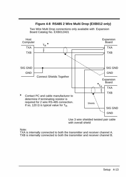
Figure 4-8 RS485 2 Wire Multi Drop (EXB012 only)
Use 3 wire shielded twisted pair cable with overall shield
* Contact PC and cable manufacturer todetermine if terminating resistor isrequired for 2 wire RS-485 connection. If so, 120 Ω is typical value for TR.
TXA
TXB
ExpansionBoard
HostComputer
SIG GND
GND
TXA
TXB
Shields
ExpansionBoard
SIG GND
GND
*TXA
TXB
SIG GND
GND
TR
*TR
Connect Shields Together
Note:TXA is internally connected to both the transmitter and receiver channel A.TXB is internally connected to both the transmitter and receiver channel B.
Two Wire Multi Drop connections only available with ExpansionBoard Catalog No. EXB012A01

4-14 Setup
Control Terminal Strip ConnectionsFor Serial Mode operation, the Input/Output terminal strip of the control(J1 of the Vector and DC controls and J4 of the Inverters) is wired asshown in Figure 4-9. Connect the Enable, Forward Enable Switch,Reverse Enable Switch, External Trip and Opto Common connectionsas shown.Note: All opto-isolated outputs and analog outputs remain active while
operating in the Serial Mode.When these connections are complete, refer to Section 5 of this manualand set the software for Serial Mode.
Figure 4-9 Serial Opto Input Connections
8
9
10
16
17Common
J1*
8
9
10
16
17Common
J4**
Enable
ForwardEnable
ReverseEnable
ExternalTrip
Enable
ForwardEnable
ReverseEnable
ExternalTrip
* Series 18H, 19H, 20H, 22H and 23H controls.** Series 15H and 21H controls.Note: Open both the Forward and Reverse switches to Stop.

Section 5Software Setup
Software 5-1
Configure Control Software for Serial Operating ModeMany commands in the Serial Command Language can be usedregardless of the setting of the control’s Operating Mode parameter(such as changing and viewing parameters). However, serialcommands intended to control the motor shaft require the control be inthe Serial Mode.
Note: For EXB012A01 only, the Baud Rate, Communication Protocol,and Address selections are made using the Baldor Keypad.Refer to the appropriate control manual for the parameterselections and ranges.

5-2 Software
Action Description Display CommentsApplyPower
Display illuminates BALDORMOTORS & DRIVES
Logo isdisplayed for 5seconds.
If no fault is found andcontrol is programmed forlocal mode,OR,
STP MOTOR SPEEDLOCAL 0RPM
Display mode.
If no fault is found andcontrol is programmed forremote mode
STP MOTOR SPEEDREMOTE 0RPM
Display mode.
PressPROG key
Access programming mode. PRESS ENTER FORPRESET SPEEDS
First screen inprogrammingmode
Press or key
Scroll to Level 1 Input block PRESS ENTER FORINPUT
Input Block.
PressEnter key
First selection choice OPERATING MODEP: KEYPAD
Now in keypadmode.
PressEnter key
Flashing cursor indicatesmode can be changed
OPERATING MODEKEYPAD
Press or key
Scroll to Serial mode OPERATING MODESERIAL
Change toSerial mode.
PressEnter key
Saves mode change value OPERATING MODEP: SERIAL
Press key
Scroll to Command Selectparameter
COMMAND SELECTP: +/–10VOLTS
Now in ±10 Voltinput mode.
PressEnter key
Flashing cursor indicatesmode can be changed
COMMAND SELECT+/–10VOLTS
Press or key
Scroll to Serial mode COMMAND SELECTSERIAL
Change toSerial mode.
PressEnter key
Saves change to serialcommand select
COMMAND SELECTP: SERIAL
Control is nowin Serial mode.
PressDISP key
Returns to Display mode STP MOTOR SPEEDLOCAL 0RPM
PressLOCALkey
Changes to REMOTE(Serial) Operation
STP MOTOR SPEEDSERIAL 0RPM
Control is readyfor Serialoperation.
The control is now configured for Serial mode and the Host software canbe setup

Software 5-3
Host Computer SetupBe sure that the following items are complete:1. The Serial expansion board is installed.2. The Serial expansion board is configured for RS232, RS422 or
RS485 communication.3. The communications cable is connected between the Serial
expansion board and the PC or terminal (Host Computer).4. The Control terminal strip (J1 or J4) is wired for Serial mode.5. A Host Computer is setup and operating with a communications
software program. (If not, the Windows 3.1 Terminal Emulationprogram may be used. Microsoft Windows 3.1 or higher must beinstalled.)
If you have a communications software package installed on the Host,skip this procedure. This procedure is only for those who do not have acommunications program installed or may not know how to install one.Setup Windows 3.1 Terminal Emulation1. Power up the Host and start Windows software.2. In the “Windows Accessories Group” select “Terminal” ICON shown
in Figure 5-1.Figure 5-1 Terminal ICON

5-4 Software
3. Select “Communications” from the Settings pull down menu withinTerminal program.
4. Set the communications settings as shown in Figure 5-2 or asappropriate for the Communications expansion board settings.Settings shown are:
9600 Baud rate8 Data Bits1 Stop BitNo ParityNone Flow ControlCOM1 port of Host
Figure 5-2 Communications Settings

Software 5-5
5. Select “Binary Transfers” from the Settings pull down menu withinTerminal program.
6. Set the Binary Transfer protocol to XModem/CRC.7. Close menu and save the settings.8. Terminal Communications settings are now complete.
Serial Mode Control Setup1. Power up the control.2. Type “ID” at the host keyboard. A list of Power Base ID settings,
and other information should appear on your CRT display. Asample display is shown in Figure 5-3.
Note: You must use upper case characters. The control will not recognize lower case commands.
Figure 5-3 Sample Power Base ID DisplayIDPower Base ID = 1000 - 0000 - 0101
STD CT STD VT QT CT QT VT PRESENTCONT CUR = 15.2 9.6 15.2 15.2 15.2 A RMSPEAK CUR = 30.4 17.5 19.2 17.5 30.4 A RMSRATED PWM = 2.5 2.5 8.0 8.0 2.5KHzCURRENT SCALING = 6.08 A/VDC BUS VOLTAGE = 325VCONTROLLER TEMP = 24.6 C
Use the Serial Command Language described in Section 6 of thismanual to communicate with the Control. As an example:P1001 700 changes the value of parameter 1001 (Preset Speed
#1 refer to control manual parameters) from itspresent value to 700 RPM.
V30 Changes the velocity to 30 RPM.E Enables the drive, motor rotates.S Stops and disables the drive.

5-6 Software
If you type P (by itself) and press enter, a listing of all parameter valuesis displayed as follows:PP1001 =0.00 P1002 =0.00 P1003 =0.00 P1004 =0.00 P1005 =0.00P1006 =0.00 P1007 =0.00 P1008 =0.00 P1009 =0.00 P1010 =0.00P1011 =0.00 P1012 =0.00 P1013 =0.00 P1014 =0.00 P1015 =0.00P1101 =3.0 P1102 =3.0 P1103 =0 P1104 =3.0 P1105 =3.0P1106 =0 P1201 =7.00 P1202 =3.0 P1203 =3.0 P1204 =0P1301 =0 P1302 =0 P1303 =1 P1304 =1 P1305 =1P1306 =1 P1307 =0 P1308 =0 P1309 =0 P1401 =1P1402 =1 P1403 =0 P1404 =0.00 P1405 =2.00 P1406 =0P1501 =0 P1502 =1 P1503 =2 P1504 =6 P1505 =200P1506 =100 P1507 =1750 P1508 =0 P1509 =8 P1510 =100P1511 =100 P1512 =1 P1601 =1750 P1602 =0 P1603 =0P1604 =0 P1605 =150 P1606 =10 P1607 =1.00 P1608 =0P1609 =31 P1610 =0 P1611 =61.200 P1612 =61.200 P2001 =0P2002 =0 P2003 =1750 P2004 =31.00 P2005 =2.5 P2006 =0.004P2101 =5 P2102 =0/1000P2103 =– P2201 =1 P2202 =0P2203 =0 P2204 =0 P2205 =0 P2301 =1 P2302 =0P2303 =0 P2304 =1 P2305 =100 P2306 =0 P2401 =0P2402 =0.00 P2403 =9999 P2501 =460 P2502 =61.2 P2503 =1750P2504 =60.0 P2505 =0 P2506 =1024 P2507 =0 P2508 =1P2601 =0 P2602 =0 P2603 =0 P2701 =8 P2702 =0P2703 =1 P2704 =0.0 P2705 =10.0 P2706 =10 P2707 =0P2708 =0.00 P2709 =0 P2710 =1:1 P2711 =1:1 P2712 =1024P2801 =0 P2802 =0 P2803 = 0

Section 6Serial Command Language
Serial Commands 6-1
All commands are entered as ASCII characters followed by Enter key(hex OD). The Enter “End of Line” character prompts the control toprocess the command. The Backspace character (hex 08 or Control-H)deletes the character to the left of the cursor. Control-X (hex18) deletesthe line the cursor is on.Some commands in the Serial Command Language require the controlto be in the Serial Operating Mode. These commands are considered“Protected Commands”. All commands are case sensitive(UPPERCASE and lowercase).ACK_ONThis command reports the total character string received.Note: This command is not available for Vector, DC or Servo
controls.ACK_OFFThis command turns off the “ACK_ON” command.Note: This command is not available for Vector, DC or Servo
controls.Ax(Address) Multi-Drop CommandThe address command is used in multi-drop systems to select thecontrol identified by x, for communication. Where x = control addressfrom 0 - 31. Commands will be received and processed by the controlwith x address until another address is given, or a global AA (AddressAll) command is given. The control address is set by the DIP switcheslocated on the serial expansion board.When the control receives an address command it echoes back itscontrol address to acknowledge that it is now on line. The Controladdress 0 will receive and process commands unless another addressis given.

6-2 Serial Commands
AA(Address All) Multi-Drop CommandThis command is used in multi-drop systems to direct a command(s) toALL controls regardless of their individual control ID. The Address Allremains active until another address is given.AUn (Auto-Tune) Protected CommandThe Auto-Tune command starts the motor tuning procedure. The controlmust be externally enabled (pin 8 of the terminal strip, see Figure 4-9).Refer to the parameter list in the Control Installation and OperatingManual for the auto-tuning numbers (AU1-AU6) that correspond to thetest. The test will either pass or fail. If the test fails, refer to the controlmanual.Note: This command is not available for Series 15H or 21H
Inverters.Note: The CALC command MUST be given before running the
auto-tuning tests.C (Clear)This command clears an existing fault. The control will resume operationif an E (Enable) command is given and no faults are present.CALCCalculates specific parameters based on motor rating values. Thiscommand must be given before the auto-tune tests are run. Motor ratinginformation must be programmed into control using the operator keypador “P” serial command before CALC command is run.Note: This command is not available for Series 15H or 21H
Inverters.

Serial Commands 6-3
D (Disable) Protected commandDisables control output.Note: The current status of the control can be retrieved by using the ST
(STATUS) command.DL (Download)Begins the download procedure. All parameters for the currentparameter table of the control are downloaded to a host file using thestandard XMODEM protocol. Control-X can be used to cancel theprocedure. If the XMODEM procedure is not started within 60 seconds,the DL command aborts.E (Enable) Protected commandEnables control output. External enables at the control terminal stripmust be closed and the control must be in the Serial Operating Mode.For safety reasons the control will not enable unless a valid Vnnnn,Tnnnn or Mxxxxx command was previously issued.Note: The current status of the control can be retrieved by using the ST
(STATUS) command.ECHO_ONTurns on the echo character function. (Preset to do so when not in multi-drop).ECHO_OFFTurns off the echo character function. (Preset to do so when in multi-drop).

6-4 Serial Commands
F (Fault)This command returns the current fault code. Returns 0 if no faultcondition exists. See HF command.GO (Process Target Register Command)The command stored in target register will be processed. See TAR command.H (Home) Protected CommandCommands the control to go to the predefined home position atpredefined homing speed. This command is not the same as the W(position to zero) command and not intended to be used with positioningcommands.Note: This command is not available for Series 15H or 21H
Inverters.HF (Help Fault)This command returns the current fault code and gives a text definitionof the fault. Consult the troubleshooting section of your control manualfor recommended corrective action. Fault codes are defined as follows:
FaultCode Description
FaultCode Description
FaultCode Description
0 No Faults 10 Logic Supply Fault 20 User Fault Text1 Line Regen Fault 11 Overcurrent Fault 21 Lost User Data2 Encoder Loss 12 DC Bus High 22 µP Reset Fault3 Invalid Base ID 13 Following Error 23 Memory Fault4 Low Init. Bus Volts 14 Torque Proving
Fault24 Overload 1-Minute
5 Regen R PowerFault
15 DC Bus Low 25 Inverter Base ID
6 Current Sense Fault 16 Overload 3-Second 26 New Base ID7 Power Base Fault 17 Overspeed Fault 27 No EXB Installed8 Ground Fault 18 External Trip 28 Power Module Fault9 Resolver Loss 19 Int Over-Temp Fault

Serial Commands 6-5
HL (Help Log)Reports last 15 faults with time stamps. Most recent fault shown first.Gives text description of faults.HP or HPxxxx or HPxxxx nnnn (Help Parameters)The HP command can be used in three ways:1. HP gives a full list of all the parameters with a text description of the
parameter and the current parameter setting.2. HPxxxx gives a text description and current setting of a single
parameter, where xxxx is the parameter number.3. When the HPxxxx command is followed by a space and nnnn,
parameter xxxx is changed to value of nnnn. Where xxxx is a value from 0 - 9999, and nnnn is a value from 0 -9999 this is the same as Pxxxx nnnn.
Example: HP1201 P1201 JOG SPEED = 400 RPMMin value = 0, Max value = 1750, Factory value = 200
ID (Power Base ID)This command returns a listing of power base settings with control busvolts, current scaling and control temperature.Example:IDPower Base ID = 1000 - 0000 - 0101
STD CT STD VT QT CT QT VT PRESENTCONT CUR = 15.2 9.6 15.2 15.2 15.2 A RMSPEAK CUR = 30.4 17.5 19.2 17.5 30.4 A RMSRATED PWM = 2.5 2.5 8.0 8.0 2.5KHzCURRENT SCALING = 6.08 A/VDC BUS VOLTAGE = 325VCONTROLLER TEMP = 24.6 C

6-6 Serial Commands
IO (IO Status)This command returns current state of all terminal strip connections (J1for Vector, Servo and DC controls and J4 for Inverters). The J1 or J4status is as follows:Pins 2, 4, and 5 give the status of the analog inputs. A value of 0 = –10 V, 512 = 0V and 1024 = 10 V.Pins 6 and 7 are the analog outputs. They are scaled 0 - 256, where256 = the maximum value of 5 V.Jx (Jog) Protected commandJogs the motor at the rate set by the Level 1, Jog Settings Block. A Jcommand given with an x value of + or – (J+ or J–) determines thedirection of the jog. A J command given with an x value of S (JS) willstop the jog command at the decel rate specified in the Level 1, JogSettings Block.L (Log)Sends a report of the last 31 faults with time stamps, the most recentfault first. The fault numbers displayed correspond to the fault codesfound in the Troubleshooting section of the Control Installation andOperating Manual. See also HL command.M or Mxxxxx (Absolute Move) Protected commandThe M command by itself (without xxxxx) returns the last positioncommand.The M command followed by xxxxx, causes the control to enter theposition mode and move to the absolute position of xxxxx encodercounts relative to the Z (zero) position. Speed is the rate defined withthe V (positioning speed) command. Where xxxxx is an absoluteposition (signed) in encoder counts X4. Positions negative to zeroposition must be preceded with a minus sign, (–xxxxx). Maximum valueof xxxxx is 231–1 encoder counts.Note: This command is not available for Series 15H or 21H
Inverters.
Serial Commands 6-7
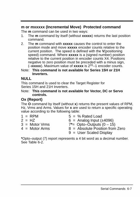
m or mxxxxx (Incremental Move) Protected commandThe m command can be used in two ways:1. The m command by itself (without xxxxx) returns the last position
command.2. The m command with xxxxx causes the control to enter the
position mode and move xxxxx encoder counts relative to thecurrent position. The speed is defined with the V(positioningspeed) command. Where xxxxx is a (signed number) positionrelative to the current position in encoder counts X4. Positionsnegative to zero position must be preceded with a minus sign,(–xxxxx). Maximum value of xxxxx is 231–1 encoder counts.
Note: This command is not available for Series 15H or 21HInverters.
NULL This command is used to clear the Target Register for Series 15H and 21H Inverters.Note: This command is not available for Vector, DC or Servo
controls.Ox (Report)The O command by itself (without x) returns the present values of RPM,Hz, Vrms and Arms. Values for x are used to return a specific operatingvalue according to the following table:1 = RPM 5 = % Rated Load 2 = HZ 6 = Analog Input (±4096) 3 = Motor Vrms 7*= Opto–Outputs (0 – 15) 4 = Motor Arms 8 = Absolute Position from Zero
9 = User Scaled Display
*Opto–output (7) report represents a 4 bit word as a decimal number.See Table 6-2.

6-8 Serial Commands
Table 6-2 Opto–Output 7
Decimal Number 4 Bit Word20, 21, 22, 23
Output Status
0 0000 No outputs are on.1 1000 Output #1 is on.2 0100 Output #2 is on.3 1100 Output #1 and 2 are on.4 0010 Output #3 is on.5 1010 Output #1 and 3 are on.6 0110 Output #2 and 3 are on.7 1110 Output #1, 2 and 3 are on.8 0001 Output #4 is on.9 1001 Output #1 and 4 are on.
10 0101 Output #2 and 4 are on.11 1101 Output #1, 2 and 4 are on.12 0011 Output #3 and 4 are on.13 1011 Output #1, 3 and 4 are on.14 0111 Output #2, 3 and 4 are on.15 1111 All outputs are on.
P or Pxxxx or Pxxxx nnnn Protected commandThe P command can be used in three ways:1. The P command by itself (without xxxx) returns a list of all the
parameter values.2. When the command is Pxxxx the current value of parameter xxxx
is returned. (Refer to the control manual Parameter List for the“Serial Mode Parameter Number” xxxx).
3. When the Pxxxx command is followed by a space and nnnn,parameter xxxx is changed to the value of nnnn. Where xxxx isthe “Serial Mode Parameter Number”, and nnnn is a value from 0 –9999.
Serial Commands 6-9
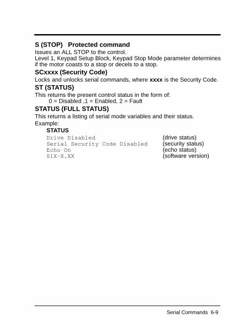
S (STOP) Protected commandIssues an ALL STOP to the control. Level 1, Keypad Setup Block, Keypad Stop Mode parameter determinesif the motor coasts to a stop or decels to a stop.SCxxxx (Security Code) Locks and unlocks serial commands, where xxxx is the Security Code.ST (STATUS)This returns the present control status in the form of:
0 = Disabled ,1 = Enabled, 2 = FaultSTATUS (FULL STATUS)This returns a listing of serial mode variables and their status.Example:
STATUSDrive Disabled (drive status)Serial Security Code Disabled (security status) Echo On (echo status) S1X–X.XX (software version)

6-10 Serial Commands
T or Tnnnn (Torque command) Protected commandThe T command can be used in two ways.1. When the T command is alone it enters torque control and returns
the last torque command given.2. When followed by a numeric value it enters the torque mode and
commands the value, where nnnn is a numeric value. nnnn =±2048 is equal to the control current limit. nnnn = ±1024 is equal to half of the control current limit.
Note: This command is not available for Series 15H or 21HInverters.
Note: Negative torques are indicated by a –nnnn (positive values maybe entered by +nnnn but this is optional). T+ or T– will(depending on the present torque direction) cause the control toreverse direction using the last commanded torque value.
TAR xxxx (Target Register)Store a command to the Target Register for execution at a later time(GO command) where xxxx is any serial command in it normal format.This TAR command uses a target register (temporary data storagelocation) to store the command xxxx given after the space. This xxxxcommand is stored and processed when a GO command is given. Thisis useful when synchronizing multiple controls on a common mark. Forexample, on a 3 axis system, each control could be given a “target”position and all 3 could be started at the same time with a global GOcommand.

Serial Commands 6-11
TP (Test Points)View the list of captured test point data in the buffer.The test point bufferconsists of two channels. When the control is enabled the buffercontinuously captures data. When the control becomes disabled or afault occurs, the data capture stops and the buffer retains the last 32points of data per channel.Each channel can be set to buffer internal variables by setting P3001(channel 1) and P3002 (channel 2) as follows:Note: Not all of the variables listed are used with the Series 15H
and 21H Inverters.0 = Velocity 8 = Field Weaken 16 = Speed Command1 = Elec Angle 9 = Following ERR 17 = Overload Accum2 = ABS Command 10 = Quad Control 18 = Phase 2 Current 3 = PWM Voltage 11 = Direct Control 19 = Phase 3 Current 4 = Direct Current 12 = AC Voltage 20 = Position 5 = CMD Direct CUR 13 = Bus Voltage 21 = Serial Command6 = Quad Current 14 = Vector Angle 22 = Delta Count 7 = CMD Quad CUR 15 = Power
TPF (Test Point File)This command starts a download of all the test points to a hostcomputer file. Follow the same procedure as the DL command.TPT (Test Point Trigger)The test point buffer is normally filled when the control is enabled andthe buffer stops filling when the control is disabled or a fault occurs. Ifthe TPT command is given, the test point buffer is filled for 255 pointsafter the next “Enter” is received (example: TPT, Enter, Vnnnn, Enter).The test points can then be viewed by using the TP command.UL (Upload)This command begins the Upload procedure using XMODEM protocol.It uploads a parameter file from the computer to the control. Control–Xcan be used to cancel the procedure. If the XMODEM procedure is notstarted within 60 seconds the command aborts.

6-12 Serial Commands
V or Vnnnn (Velocity Command) Protected commandThe V command can be used in two ways:1. The V command by itself returns the last velocity command.2. The V command is followed by a numeric value nnnn, it enters the
velocity mode and commands that value equal to RPM (for thevector, servo and DC controls) or Hz (for Inverters).
Note: Negative velocities are denoted by –nnnn (positive values maybe entered by +nnnn but this is optional). V+ or V– (dependingon the current direction) will cause the control to reversedirection using the last commanded velocity value.
VX or VXnnn (Velocity Command/256) Protected commandThe VX is similar to the V command except that it is used to commandfractional RPM or less than 1 RPM.Example:VX128 = 0.5 RPM; VX256 = 1RPM; VX384 = 1.5 RPM.v or vxxxx (Positioning Speed)vxxxx changes the maximum speed used in positioning commands.Where xxxx is a velocity value.Note: Value is preset to 0 at control power up.Note: This command is not available for Series 15H or 21H Inverters.W (Position to Zero)This command positions the control to the absolute ZERO position asdefined with the Z command. The command moves at the definedpositioning “speed” as set by a v command. This is NOT the same asthe H (Home) command.Note: This command is not available for Series 15H or 21H
Inverters.Z (Set Current Position to Zero)This command sets the current position to zero. It is to be used onlywith positioning commands.Note: This command is not available for Series 15H or 21H Inverters.

Section 7Communication Using a Modem
Communication Using a Modem 7-1
Series H Controls Remote Modem Setup WARNING: Use extreme care when in the Remote mode.
You can gain complete control of the Series H control andmotor operation from any phone line available. You caninitiate an operation that could be hazardous to personnelor equipment from a remote location. Baldor assumes no liability for use, installation orapplication of the information contained in this document.
You must have a PC compatible computer to configure the modem. Youwill temporarily connect the modem to the computer, configure themodem then install the modem at the Series H control.Modem Type: US Robotics Sportster 28,800 (External).Modem Setup: Stand alone operation setup (3 wire interface).A three wire interface consists of Receive data, Transmit data, andground. Hardware flow control is not supported. Use the followingsteps to setup the modem for software flow control.Set Modem Switches (Switches are located on rear panel.)1. Rotate modem so rear panel faces you Figure 7-1. (Table 7-1
defines the function of each switch.)2. Set switches 1 - 8 as follows:
1 & 2 = Down 4 = Down 8 = Down3 = Up 5, 6 & 7 = Up
Figure 7-1 Modem Rear Panel

7-2 Communication Using a Modem
3. Temporarily set Switch 7 Down to prevent loading defaults at powerup.
4. Connect the modem to your computer and AC power as instructedin the modem manual. You must have communications softwareloaded on your computer to perform this procedure.
5. Start your communications software and download the followingcommands to the modem (make a software flow control templateand disable flow control): AT&F2&W<ENTER> AT&H0<ENTER> AT&K0<ENTER> AT&W0<ENTER>
6. Turn modem power OFF then back ON to load the changes.7. Set Switch 7 UP to its normal position. The modem is now ready to
use.Note: You only need to do this procedure during the initial installation
and if the modem is replaced with a different modem for somereason.
Table 7-1 Modem Switch Settings
DIPSwitch
Position Description(Applies to US Robotics Sportster 28,800 Only)
1 Down Data Terminal Ready; Down – override DTR2 Down Result Codes; Down – Numeric Codes3 Up Result Codes; Up – Suppress Codes4 Down Off–line Commands; Down – No echo commands5 Up Auto Answer; Up – On first ring (or more if set in RAM)6 Up Carrier Detect; Up – Normal7 Up Load Defaults; Up – Load NV RAM defaults8 Down Smart/Dumb Mode; Down – Smart Mode

Communication Using a Modem 7-3
8. Turn OFF modem power.9. Disconnect the modem from your computer.10. Connect the modem to the RS232 port of the Series H control.11. Connect the phone line to the modem Phone Jack.12. Apply power to the modem. The modem is now ready to auto
answer.
WARNING: Use extreme care when in the Remote mode.You can gain complete control of the Series H control andmotor operation from any phone line available. You caninitiate an operation that could be hazardous to personnelor equipment from a remote location.
Baldor assumes no liability for use, installation orapplication of the information contained in this document.
You may communicate with the drive from any where in the world. Usethe instructions located in this manual to set parameter values andoperate the control. You should always call someone at the site toinform them to keep personnel away from the drive during your remotetesting.Auto answer modems from other manufacturers may be used as long asthey are configured in a similar manner as outlined in these instructions.

7-4 Communication Using a Modem
RS
232
Cab
leR
S23
2 C
able
Mod
em,
US
Rob
otic
sM
odem
, any
14,
400
or28
,800
BP
S E
xter
nal.
28,8
00B
PS
mod
em.
Lapt
op o
rO
ther
Com
pute
r

Baldor Electric Company Printed in USAMN1310 4/03 C&J1500
BALDOR ELECTRIC COMPANYP.O. Box 2400
Fort Smith, AR 72902–2400(479) 646–4711
Fax (479) 648–5792

Serial Command LanguageAll commands are entered as ASCII charactersfollowed by Enter key (hex OD). Enter = “End of Line” character The Backspace (hex 08 or Control-H) deletescharacter to left. Control-X (hex18) deletes the line the cursor is on.
“Protected Commands” require the control to be inthe Serial Operating Mode.
All commands are case sensitive (uppercase andlowercase).
ACK_ON
This command reports the total character stringreceived.
Note: This command is not available forVector, DC or Servo controls.
ACK_OFF
This command turns off the “ACK_ON” command.
Note: This command is not available forVector, DC or Servo controls.
Ax(Address) Multi-Drop Command
In multi-drop systems, selects the control ataddress x (0-31).Normally address 0 unless another address isgiven.
AA(Address All) Multi-Drop Command
Used in multi-drop systems to direct a command(s)to ALL controls.
AUn (Auto-Tune) Protected Command
Note: The CALC command MUST be givenbefore running the auto-tuning tests.
For Auto-Tune, the control must be externallyenabled (pin 8 of the terminal strip. AU1-AU6 canbe commanded. The test will either pass or fail. Ifthe test fails, refer to the control manual.
Note: This command is not available forSeries 15H or 21H Inverters.
C (Clear)
This command clears an existing fault. The controlwill resume operation if an E command (Enable) isgiven and no faults are present.
CALC
Calculates values for specific parameters based onmotor rating values. Motor rating information mustbe programmed into control using the operatorkeypad or “P” serial command before CALCcommand is run. The CALC command must begiven before the auto-tune tests are run.
Note: This command is not available forSeries 15H or 21H Inverters.
D (Disable) Protected command
Disables control output.
Note: The current status of the control can beretrieved by using the ST (STATUS)command.
DL (Download)
Begins the download of all parameters for thecurrent parameter table. Download to the hostusing XMODEM protocol. Control-X cancels theprocedure.
E (Enable) Protected command
Enables control output. External enables at controlterminal strip must be closed and control must be inSerial Operating Mode.
For safety reasons the control will not be Enabledunless a valid Vnnnn, Tnnnn or Mxxxxx commandwas previously issued.
Note: The current status of the control can beretrieved by using the ST (STATUS)command.
ECHO_ON
Turns on the echo character function. (Preset to do so when not in multi-drop).
ECHO_OFF
Turns off the echo character function. (Preset to do so when in multi-drop).
F (Fault)
This command returns the current fault code. 0 =no fault.
GO (Process Target Register Command)
Processes commands stored in target register. SeeTAR.
H (Home) Protected Command
Commands the drive to the home position.
Note: This command is not available forSeries 15H or 21H Inverters.
HF (Help Fault)
Returns the current fault code with a text definitionof the fault.
FaultCode Description
FaultCode Description
FaultCode Description
0 No Faults 10 Logic SupplyFault
20 User FaultText
1 Line RegenFault
11 OvercurrentFault
21 Lost UserData
2 EncoderLoss
12 DC Bus High 22 µP ResetFault
3 Invalid BaseID
13 Following Error
23 MemoryFault
4 Low Init. BusVolts
14 Torque Prov-ing Fault
24 Overload1-Minute
5 Regen RPower Fault
15 DC Bus Low 25 Inverter BaseID
6 CurrentSense Fault
16 Overload3-Seconds
26 New Base ID
7 Power BaseFault
17 OverspeedFault
27 No EXBInstalled
8 Ground Fault 18 External Trip 28 Power Mod-ule Fault
9 ResolverLoss
19 Int Over-Temp Fault
HL (Help Log)
Reports last 15 faults with time stamps.
HP or HPxxxx or HPxxxx nnnn (HelpParameters)
1. HP lists all parameters with a text descriptionof the parameter and the current parametersetting.
2. HPxxxx gives description and current settingof a single parameter, where xxxx is theparameter number.
3. HPxxxx nnnn, causes parameter xxxx to bechanged to value of nnnn.
ID (Power Base ID)
Llists power base settings with control bus volts,current scaling and control temperature.
IO (I/O Status)
Displays current state of all terminal strip I/Oconnections. For pins 2, 4, and 5; 0 = –10 V, 512 =0V and 1024 = 10 V. For pins 6 and 7; 0 - 256 = 0-5V.
Jx (Jog) Protected command
Jogs the motor. (J+ or J–) sets jog direction. JS will stop the jog command.
L (Log)
Displays the last 31 faults with time stamps. Seealso HL.
M or Mxxxx (Absolute Move) Protectedcommand
M command by itselfreturns the last positioncommand.
Mxxxxx commandcauses the control to enterposition mode and move to the absolute position ofxxxxx encoder counts relative to the Z (zero)position. xxxxx is an absolute position (signed)and a maximum value of xxxxx is 231–1 encodercounts.
Note: This command is not available forSeries 15H or 21H Inverters.
m or mxxxxx (Incremental Move) Protectedcommand
The m command can be used in two ways:
1. m command returns the last positioncommand.
2. mxxxxx causes the control to enter positionmode and move xxxxx encoder countsrelative to the current position. Maximumvalue of xxxxx is 231–1 encoder counts.
Note: This command is not available forSeries 15H or 21H Inverters.
NULL
Clear the Target Register for Inverters.
Note: This command is not available forVector, DC or Servo controls.
FL1310 Serial Command Summary

Ox (Report)
Displays present values according to the following:
1 = RPM 5 = % Rated Load 2 = HZ 6 = Analog Input (+/– 4096) 3 = Motor Vrms 7*= Opto–Outputs (0 - 15) 4 = Motor Arms 8 = Absolute Position from Zero
9 = User Scaled Display
*Opto-output (7) reports a 4 bit word.
DecimalNumber
4 Bit Word20, 21, 22, 23
Output Status
0 0000 No outputs are on.1 1000 Output #1 is on.2 0100 Output #2 is on.3 1100 Output #1 and 2 are on.4 0010 Output #3 is on.5 1010 Output #1 and 3 are on.6 0110 Output #2 and 3 are on.7 1110 Output #1, 2 and 3 are on.8 0001 Output #4 is on.9 1001 Output #1 and 4 are on.10 0101 Output #2 and 4 are on.11 1101 Output #1, 2 and 4 are on.12 0011 Output #3 and 4 are on.13 1011 Output #1, 3 and 4 are on.14 0111 Output #2, 3 and 4 are on.15 1111 All outputs are on.
P or Pxxxx or Pxxxx nnnn Protected command
1. P command displays a list of all parametervalues.
2. Pxxxx displays the current value of parameterxxxx.
3. Pxxxx nnnn, parameter xxxx is changed tovalue nnnn.
S (STOP) Protected command
Issues an ALL STOP to the control.
SCxxxx (Security Code)
Lock/unlock serial commands, xxxx =SecurityCode.
ST (STATUS)
Displays control status: 0 = Disabled ,1 = Enabled,or 2 = Fault
STATUS (FULL STATUS)
Displays listing of serial mode variables and status.
T or Tnnnn (Torque command) Protectedcommand
1. T command displays the last torque commandgiven.
2. Tnnnn commands torque mode with controlcurrent limit (±2048 = the control current limit,±1024= 1/2 control current limit. + or – valuescause direction to reverse).
Note: This command is not available forSeries 15H or 21H Inverters.
TAR xxxx (Target Register)
Store a command in Target Register
TP (Test Points)
Display test point data in the buffer.
P3001 (channel 1) and P3002 (channel 2) asfollows:
0 = Velocity 8 = Field Weaken 16 = Speed Command1 = Elec Angle 9 = Following ERR 17 = Overload Accum2 = ABS Command 10 = Quad Control 18 = Phase 2 Current 3 = PWM Voltage 11 = Direct Control 19 = Phase 3 Current 4 = Direct Current 12 = AC Voltage 20 = Position 5 = CMD Direct CUR 13 = Bus Voltage 21 = Serial Command6 = Quad Current 14 = Vector Angle 22 = Delta Count 7 = CMD Quad CUR 15 = Power
Note: Not all of the variables listed are usedwith the Series 15H and 21H Inverters.
TPF (Test Point File)
Download all the test points to a host computer file.
TPT (Test Point Trigger)
The test point buffer is filled for 255 points after thenext “Enter”.
UL (Upload)
Upload from host using XMODEM protocol.Control–X cancels.
V or Vnnnn (Velocity Command) Protectedcommand
1. V displays the last velocity command.2. Vnnnn enters the velocity mode at that RPM
or Hz. + or – values cause direction to reverse.
v or vxxxx (Positioning Speed)
vxxxx changes the maximum spped used inpositioning commands. Where xxxx is a velocityvalue.
W (Position to Zero)
Positions the drive to the absolute ZERO position(Z).
Note: This command is not available forSeries 15H or 21H Inverters.
Z (Set Current Position to Zero)
This command sets the current position to zero. It is to be used only with positioning commands.
Note: This command is not available forSeries 15H or 21H Inverters.
RS-232 Switch Settings
12
34
Side View
56
78
ON OFF
All switches shown in OFF
position.
OFF
OFF
OFF
OFF
8
OFF
OFF
OFF
OFF
7
OFF
OFF
OFF
OFF
6
OFF
OFF
OFF
OFF
5
OFF
OFF
OFF
OFF
43
OFF
ON
OFF
ON
2
ON
OFF
OFF
ON
1
OFF
OFF
OFF
OFF
OFF
OFF
OFF
OFF
ON
OFF
OFF
OFF
OFF
OFF
1200 Baud
4800 Baud
9600 Baud
19200 Baud
Description
E, 7, 1
N, 8, 1
Switch Number
DIP Switch
OTHER
JP3RS232
JP24 WIRE
2 WIRE
NO TERM
TERM R
JP1
RS422/485EXB002A01
RS232EXB001A01
RS-422/485 Switch Settings
Switch NumberDescription 1 2 3 4 5 6 7 8Address 0 OFF OFF OFF OFF OFF
Address 1 ON OFF OFF OFF OFF
Address 2 OFF ON OFF OFF OFF
Address 3 ON ON OFF OFF OFF
Address 4 OFF OFF ON OFF OFF
Address 5 ON OFF ON OFF OFF
Address 6 OFF ON ON OFF OFF
Address 7 ON ON ON OFF OFF
Address 8 OFF OFF OFF ON OFF
Address 9 ON OFF OFF ON OFF
Address 10 OFF ON OFF ON OFF
Address 11 ON ON OFF ON OFF
Address 12 OFF OFF ON ON OFF
Address 13 ON OFF ON ON OFF
Address 14 OFF ON ON ON OFF
Address 15 ON ON ON ON OFF
Address 16 OFF OFF OFF OFF ON
Address 17 ON OFF OFF OFF ON
Address 18 OFF ON OFF OFF ON
Address 19 ON ON OFF OFF ON
Address 20 OFF OFF ON OFF ON
Address 21 ON OFF ON OFF ON
Address 22 OFF ON ON OFF ON
Address 23 ON ON ON OFF ON
Address 24 OFF OFF OFF ON ON
Address 25 ON OFF OFF ON ON
Address 26 OFF ON OFF ON ON
Address 27 ON ON OFF ON ON
Address 28 OFF OFF ON ON ON
Address 29 ON OFF ON ON ON
Address 30 OFF ON ON ON ON
Address 31 ON ON ON ON ON
Full Duplex OFF
Half Duplex ON
9600 Baud OFF OFF
19,200 Baud ON OFF
38,400 Baud OFF ON
115,200 Baud ON ON
US Robotics Modem Rear Panel
Set switches 1 - 8 as follows:1 & 2 = Down 3 = Up 4 = Down5, 6 & 7 = Up 8 = Down