TCS3 Servo System Proposed Design. Why Model? Meet Resolution Requirements What Resolution Encoder...
51
TCS3 Servo System Proposed Design
-
Upload
liliana-bryan -
Category
Documents
-
view
215 -
download
0
Transcript of TCS3 Servo System Proposed Design. Why Model? Meet Resolution Requirements What Resolution Encoder...

TCS3 Servo System
Proposed Design

Why Model?
Meet Resolution Requirements What Resolution Encoder to use? Velocity Configuration PID Values Wind Loading Tests
Tests
10 arcsec Offset 15 arcsec/sec Track Open/Closed Loop Response Wind Loading Frequency Sweep
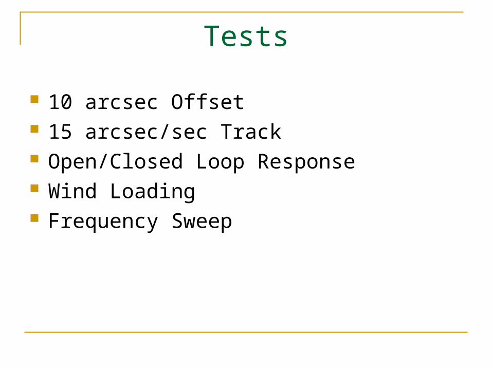
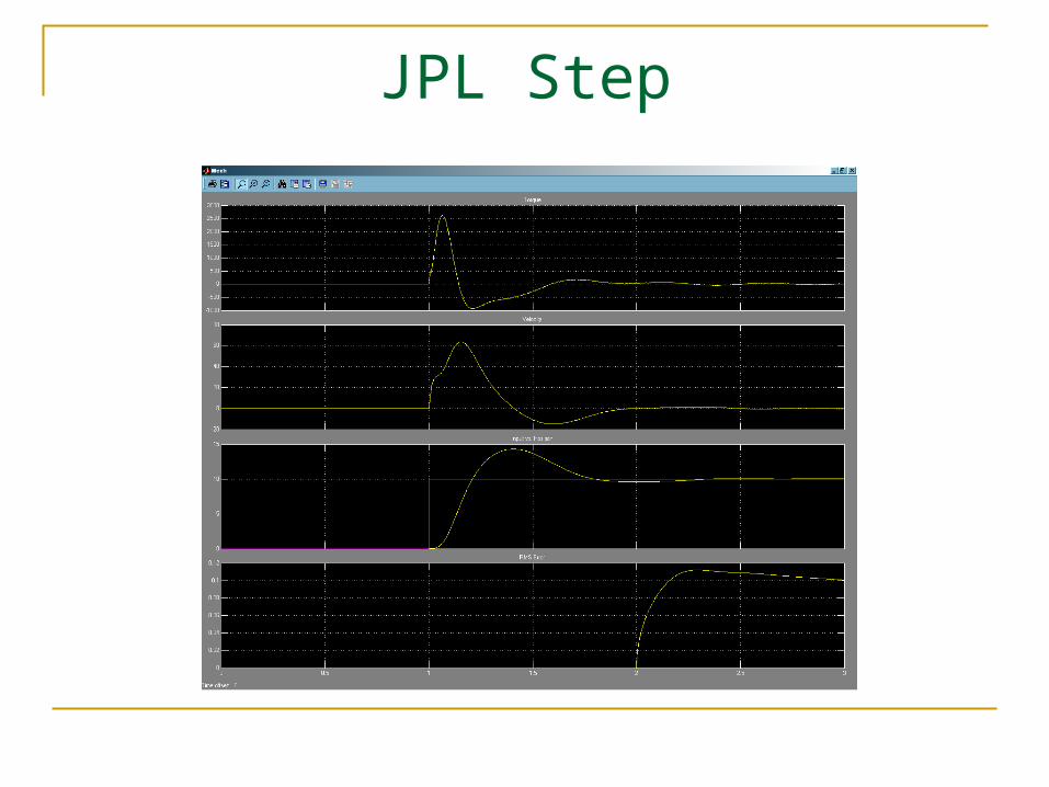
JPL System
torqueposition
v elocity
mechanical_system
s+alpha
s+beta
Transfer Fcn
Step1
Step
Ramp
Product
Mech
Manual Switch
1s
Integrator
206271
Gain9
206271
Gain8
-K-
Gain7
m
Gain6
kk1
Gain5
a1
Gain4
c3
Gain3
a2
Gain2
206271
Gain10
c4
Gain1
c1
Gain
ContinuousRMS
CRMS
|u|
Abs
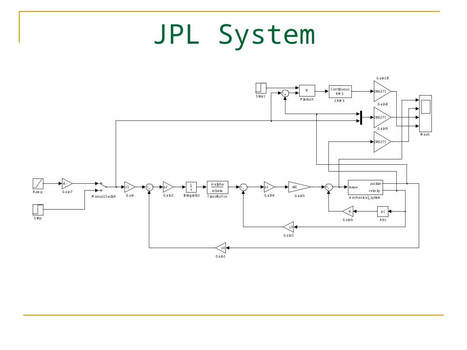
JPL Step

JPL Track

Present System vs. JPL System
Added Transfer Functions Added Quantization Blocks Added Rate Limiter Dual Opposing Motor Mechanical Model Disturbance Rejection in Velocity loop Adjust C3 and C4 gains to reflect present
system components

JPL 5 DOF Mechanical Model

Matlab 5 DOF Mechanical Model
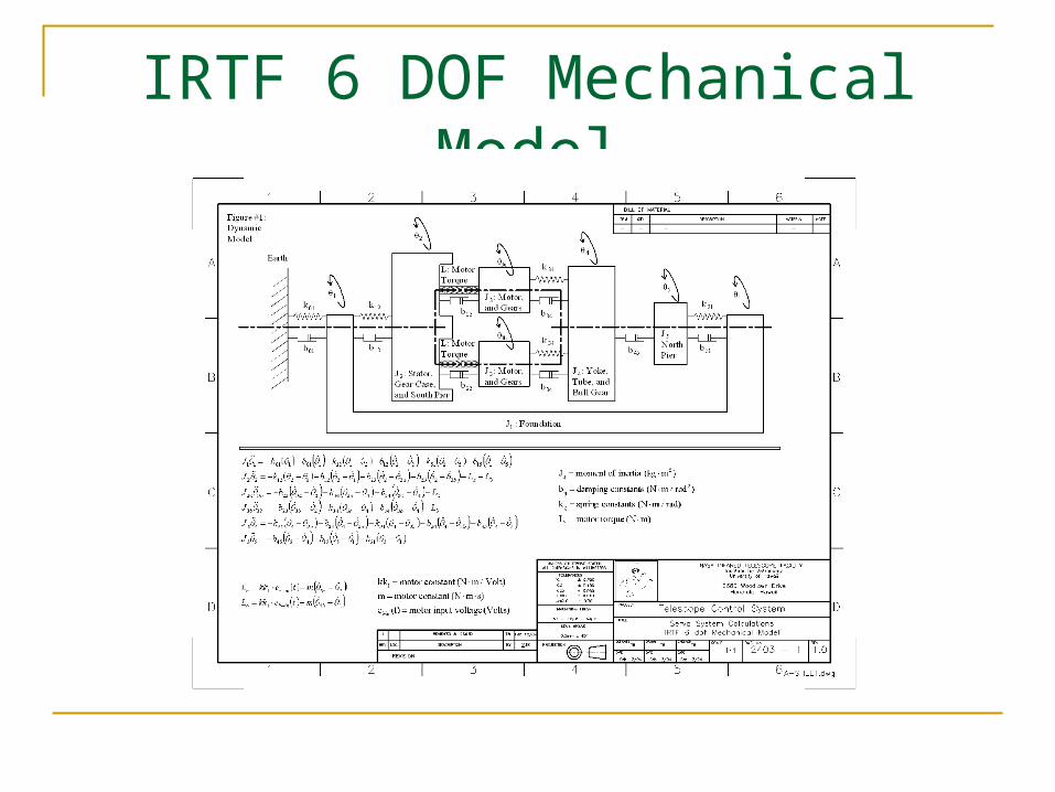
IRTF 6 DOF Mechanical Model

Matlab 6 DOF Mechanical Model
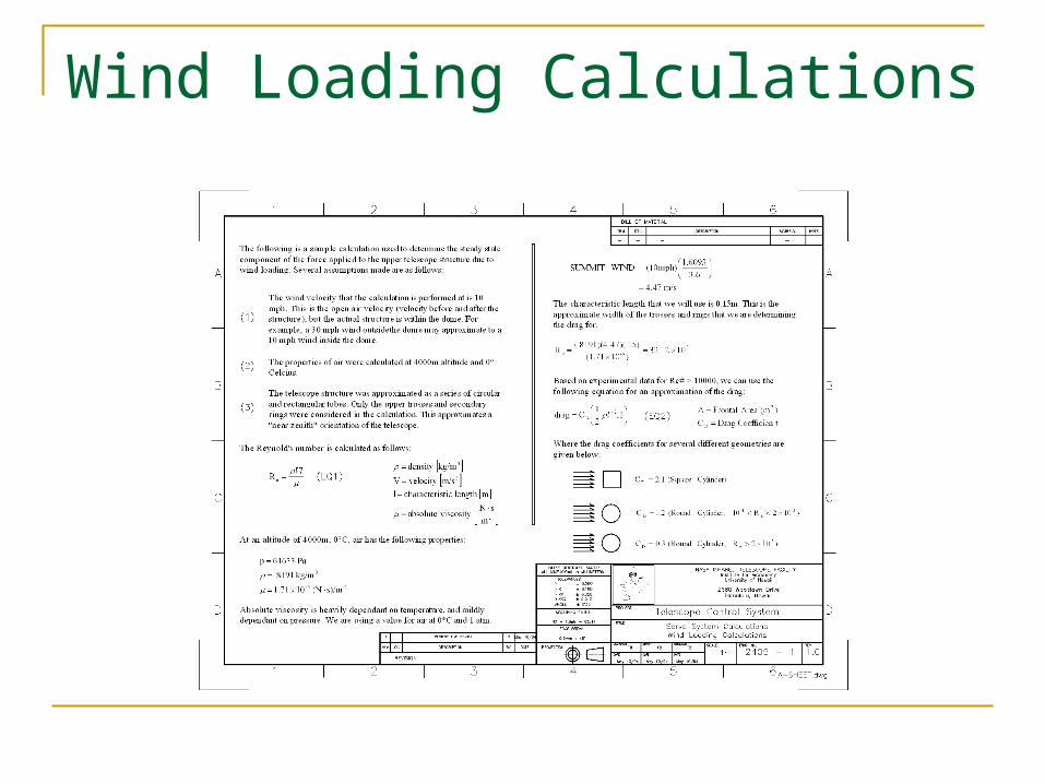
Wind Loading Calculations
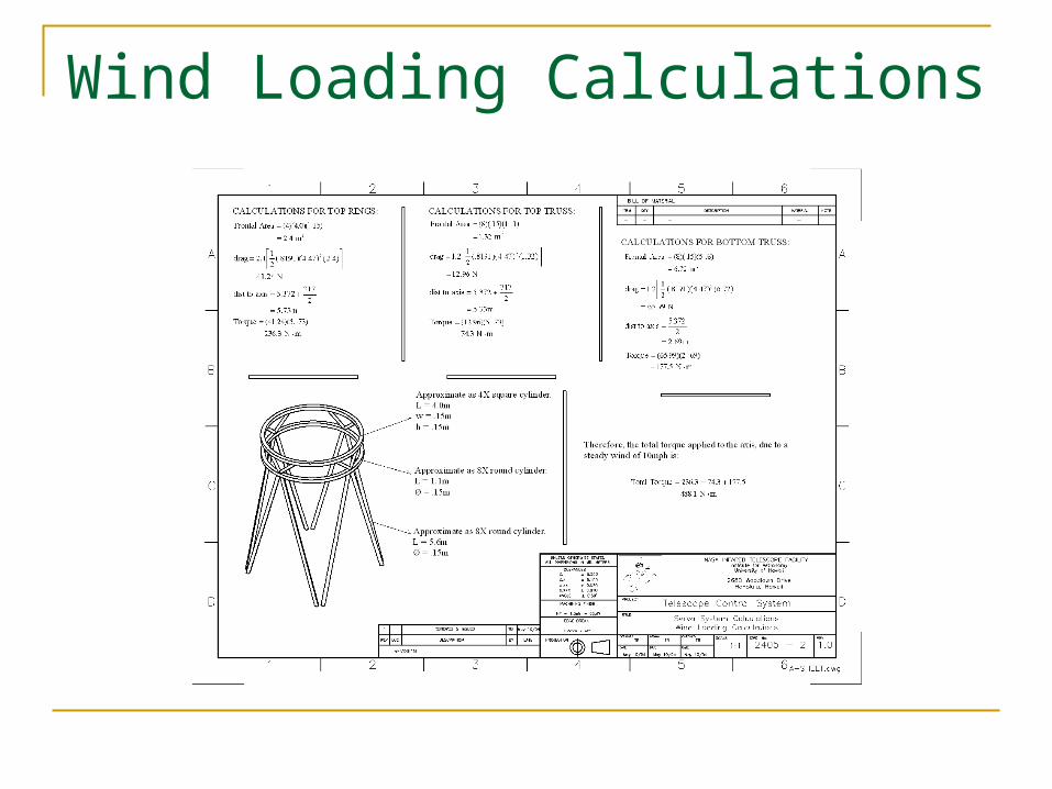
Wind Loading Calculations
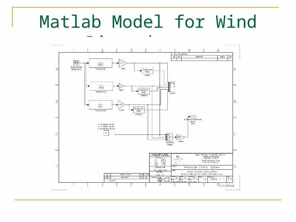
Matlab Model for Wind Disturbances

Mechanical Model Simulation
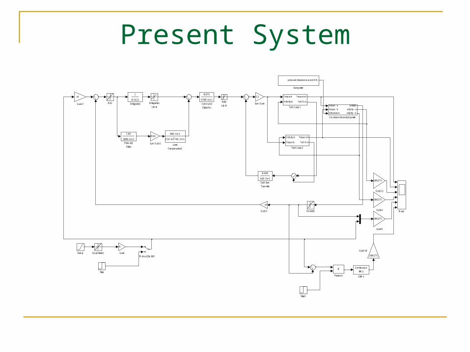
Present System
0.488
42E- 3s+1
Tach Sum
Transfer
Velocity in
Torque in
Torque out
Tach Out
Tach Loop 2
Torque in
Velocity in
Torque out
Tach Out
Tach Loop 1
0.84
Sum Gain1
1.2
Sum Gain
produced disturbance (wind) N*m
Subsystem
Step1
Step
Rate
Limit
Ramp Quantizer1
Product
Mech
Manual Switch
90E- 3s+1
3.5E- 6s +8E- 3s+12
Lead
Compensator1
Integrator
Limit
0.162s
1
Integrator
c4
Gain7
206271
Gain5
206271
Gain4
c4
Gain3
206271
Gain12
206271
Gain10
- K-
Gain
1.96
100E- 6s+1
Forward
Filter
Encoder
DAC
0.875
470E- 6s+1
Command
Filter Fcn
Continuous
RMS
CRMS
torque - a
torque - b
disturbance
position
velocity - a
velocity - b
2 motor mechanical system

Present Tachometer Loop
2
Tach Out
1
Torque out
3
660E- 6s+1
Sum Filter Positive2
0.215
220E- 6s+1
Input filter Fcn3
450E- 6s +99E- 3s2
59.4E- 9s +121.7E- 6s +48.7E- 3s+13 2
High pass
filter Fcn1
m
Gain6
kk1
Gain5
c3
Gain4
1.33
Gain
0.35
Constant
| u|
Abs
2
Velocity in
1
Torque in

Present Step

Present Track
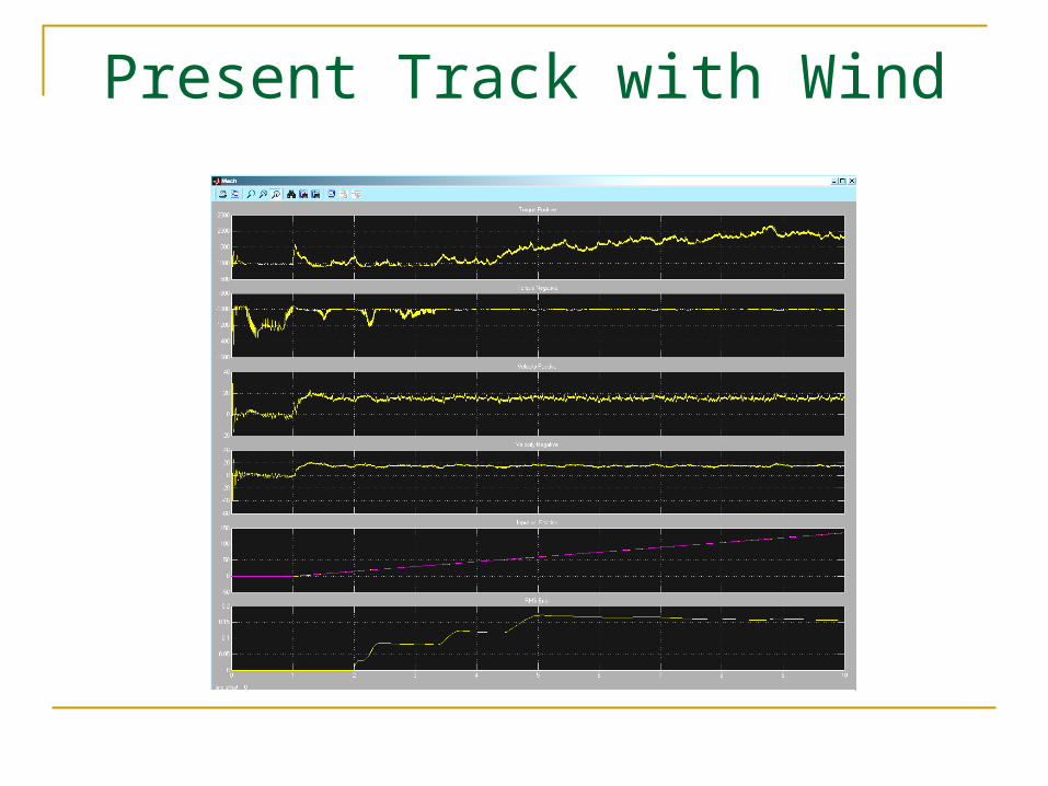
Present Track with Wind

Present System Response Testing
0.488
42E- 3s+1
Tach Sum
Transfer
Velocity in
Torque in
Torque out
Tach Out
Tach Loop 2
Torque in
Velocity in
Torque out
Tach Out
Tach Loop 1
0.84
Sum Gain1
1.2
Sum Gain
Step3
Step2
Step1
Spectrum
Analyzer2
Spectrum
Analyzer1
Rate
Limit
Pulse
Generator
Product2
Product1
Product
Mech
90E- 3s+1
3.5E- 6s +8E- 3s+12
Lead
Compensator1
Integrator
Limit
0.162s
1
Integrator
c4
Gain7
206271
Gain5
206271
Gain4
c4
Gain3
206271
Gain2
206271
Gain12
206271
Gain10
206271
Gain1
1.96
100E- 6s+1
Forward
Filter
Encoder
DAC
0
Constant
0.875
470E- 6s+1
Command
Filter Fcn
Continuous
RMS
CRMS
torque - a
torque - b
disturbance
position
velocity - a
velocity - b
2 motor mechanical system

Present Open Loop
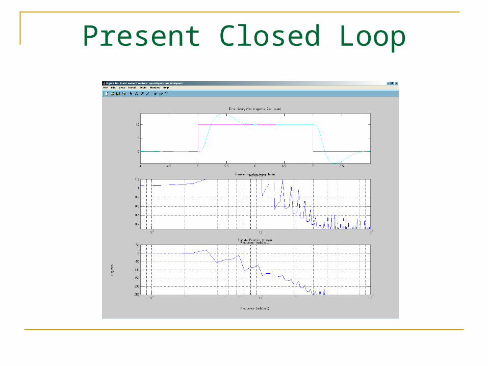
Present Closed Loop

HA 15srcsec/sec Track
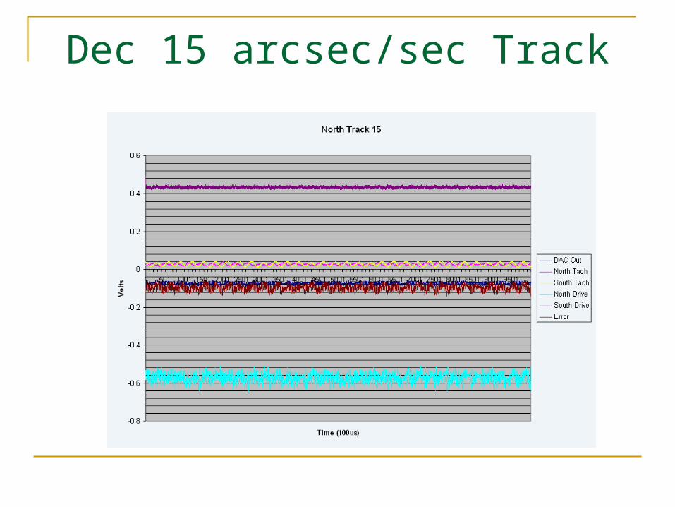
Dec 15 arcsec/sec Track

HA 600 arcsec Offset

HA 1200 arcsec Offset

Dec 1200 arcsec Offset

HA Slew
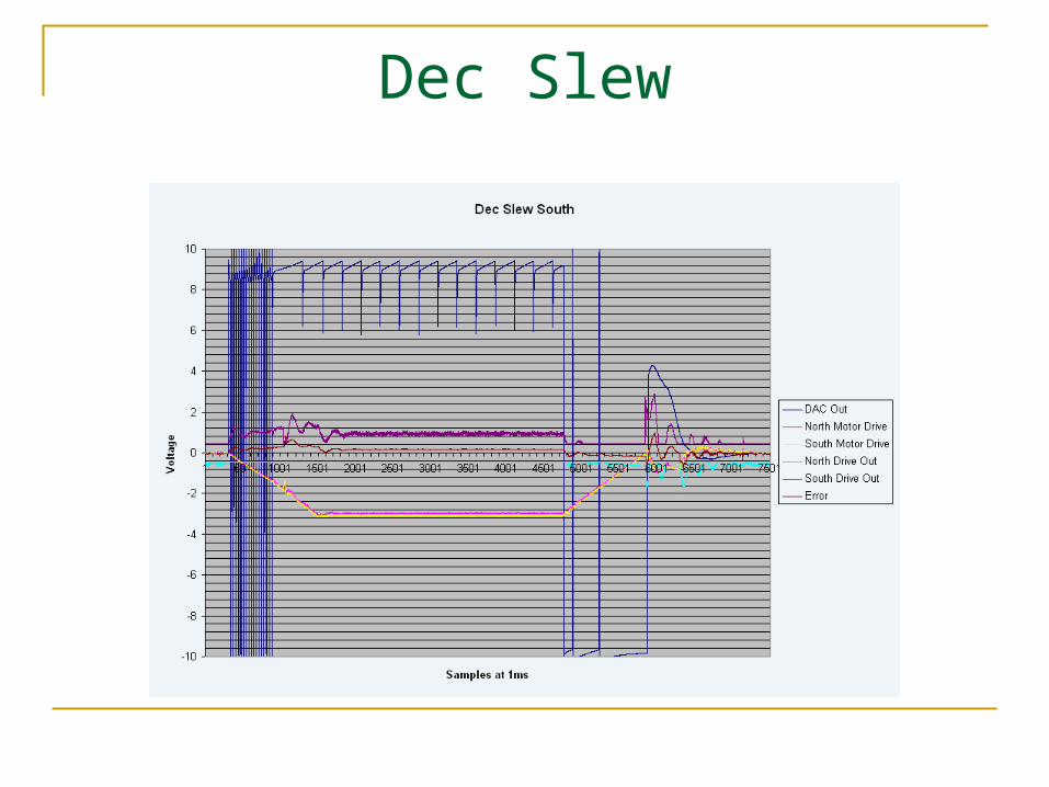
Dec Slew

Proposed System vs. Present
Delta Tau PMAC Configuration for PID Use present Tachometer Loop Adjust C4 gain for 16 bit DAC
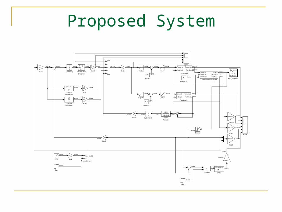
Proposed System
NCD
OutPort 1
NCD_Outport1
0.488
42E- 3s+1
Tach Sum
Transfer
Torque in
Velocity in
Torque out
Tach Out
Tach Loop 2
Torque in
Velocity in
Torque out
Tach Out
Tach Loop 1
Step1
Step
Signal
Ramp
Product
Positive
Negative
Mech
Manual Switch
Ki
Gain9
Kp
Gain8
c4
Gain7
Kfv
Gain6
206271
Gain5
206271
Gain4
c4
Gain3
Kfa
Gain2
206271
Gain12
206271
Gain10
Kd
Gain1
- K-
Gain
Encoder
T
z- 1
Discrete- Time
Integrator
z- 1
z
Discrete
Transfer Fcn1
z - 2z+12
z 2
Discrete
Transfer Fcn
DAC1
DAC
z
1
Cycle Delay1
z
1
Cycle Delay
0
Constant2
0.35
Constant1
- 0.35
Constant
Continuous
RMS
CRMS
torque - a
torque - b
disturbance
position
velocity - a
velocity - b
2 motor mechanical system
double
double
double doubledouble
double
double
double
double
double
doubledouble
double
double
double
double
double
double
doubledouble
double
double
double
double double
double double
double
double
double
double double
double
double
double
double doubledouble
double
double
doubledoubledouble
double
double
double

Proposed Tachometer Loop
2
Tach Out
1
Torque out
1
660E- 6s+1
Sum Filter1
0.215
220E- 6s+1
Input filter Fcn3
450E- 6s +99E- 3s2
59.4E- 9s +121.7E- 6s +48.7E- 3s+13 2
High pass
filter Fcn1
m
Gain6
kk1
Gain5
c3
Gain4
| u|
Abs
2
Velocity in
1
Torque in

Proposed Step 8P
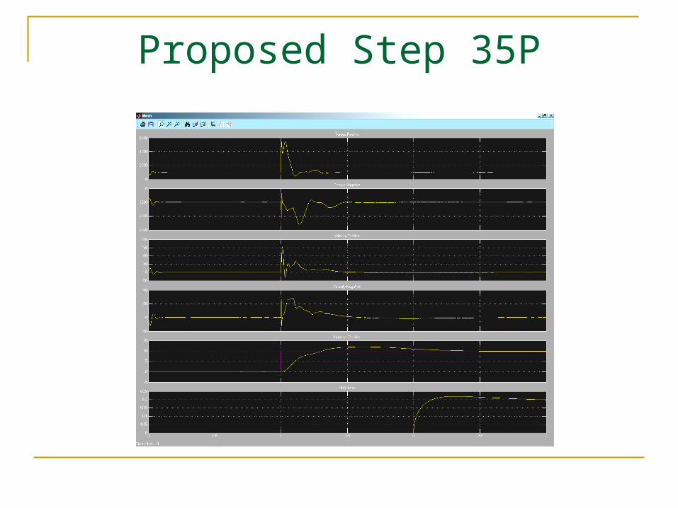
Proposed Step 35P
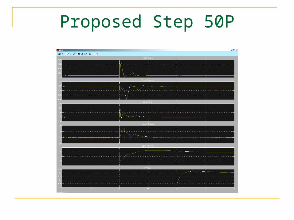
Proposed Step 50P

Proposed Step 100P
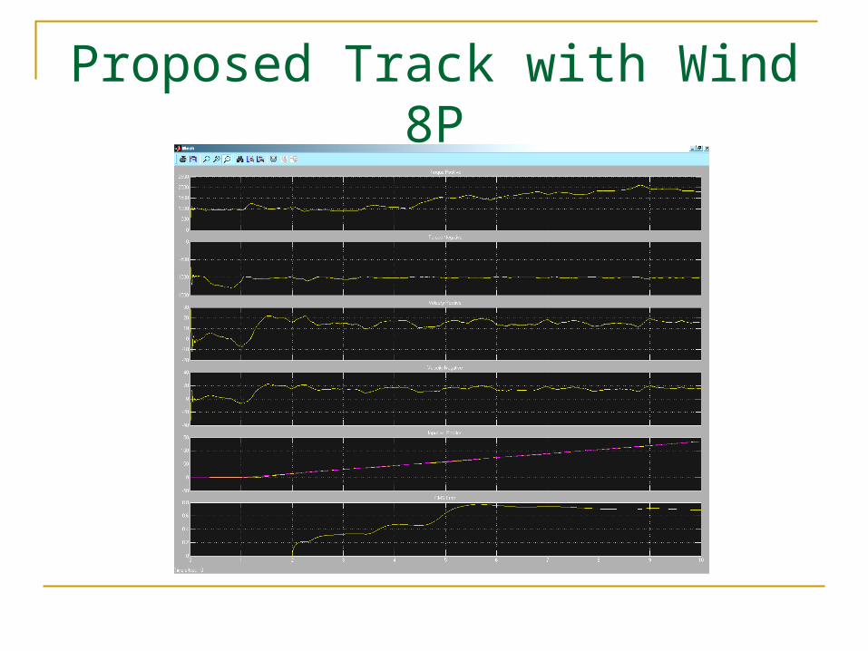
Proposed Track with Wind 8P
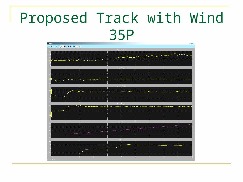
Proposed Track with Wind 35P

Proposed Track with Wind 50P
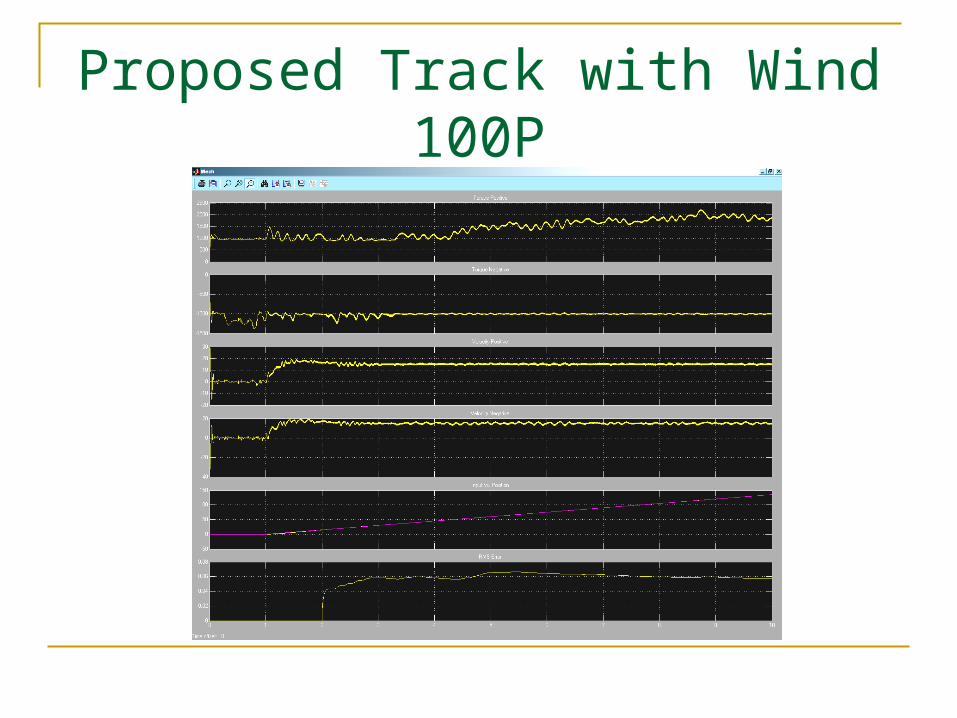
Proposed Track with Wind 100P

Proposed Track without Wind 50P

Proposed Negative Track without Wind 50P
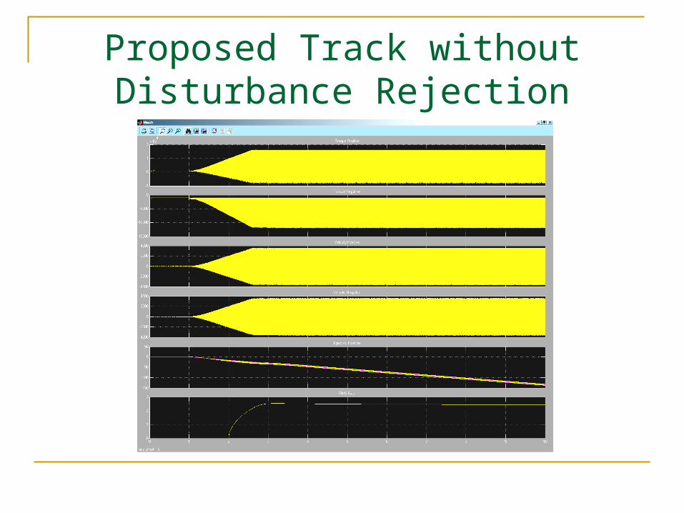
Proposed Track without Disturbance Rejection

Proposed System Response Testing
0.488
42E- 3s+1
Tach Sum
Transfer
Torque in
Velocity in
Torque out
Tach Out
Tach Loop 2
Torque in
Velocity in
Torque out
Tach Out
Tach Loop 1
Step3
Step2
Step1
Spectrum
Analyzer2
Spectrum
Analyzer1
Signal
Pulse
Generator
Product2
Product1
Product
Positive
Negative
Mech
Ki
Gain9
Kp
Gain8
c4
Gain7
Kfv
Gain6
206271
Gain5
206271
Gain4
c4
Gain3
Kfa
Gain2
206271
Gain13
206271
Gain12
206271
Gain11
206271
Gain10
Kd
Gain1
Encoder
T
z- 1
Discrete- Time
Integrator
z- 1
z
Discrete
Transfer Fcn1
z - 2z+12
z 2
Discrete
Transfer Fcn
DAC1
DAC
z
1
Cycle Delay1
z
1
Cycle Delay
0
Constant2
0.35
Constant1
- 0.35
Constant
Continuous
RMS
CRMS
torque - a
torque - b
disturbance
position
velocity - a
velocity - b
2 motor mechanical system
double
double
double
double
double
double
double
doubledouble
double
double
double
double
double
double
doubledouble
double
double
double
double double
double double
double
double
double
double double
double
double
double
double doubledoubledouble
doubledoubledouble
double
double
double
double
double
double
double
double
double
double

Proposed Open Loop
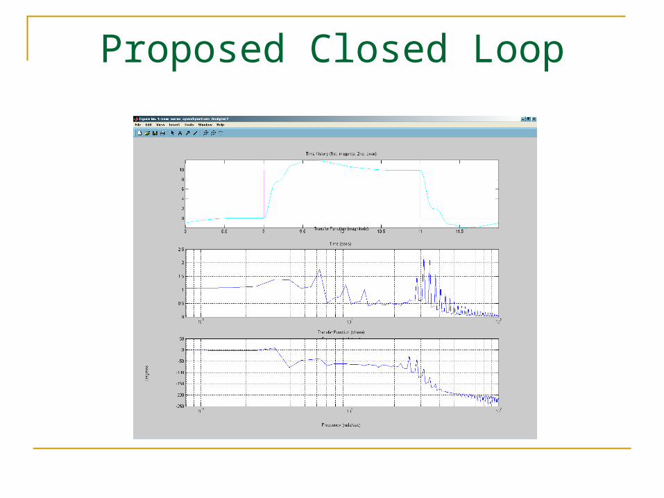
Proposed Closed Loop
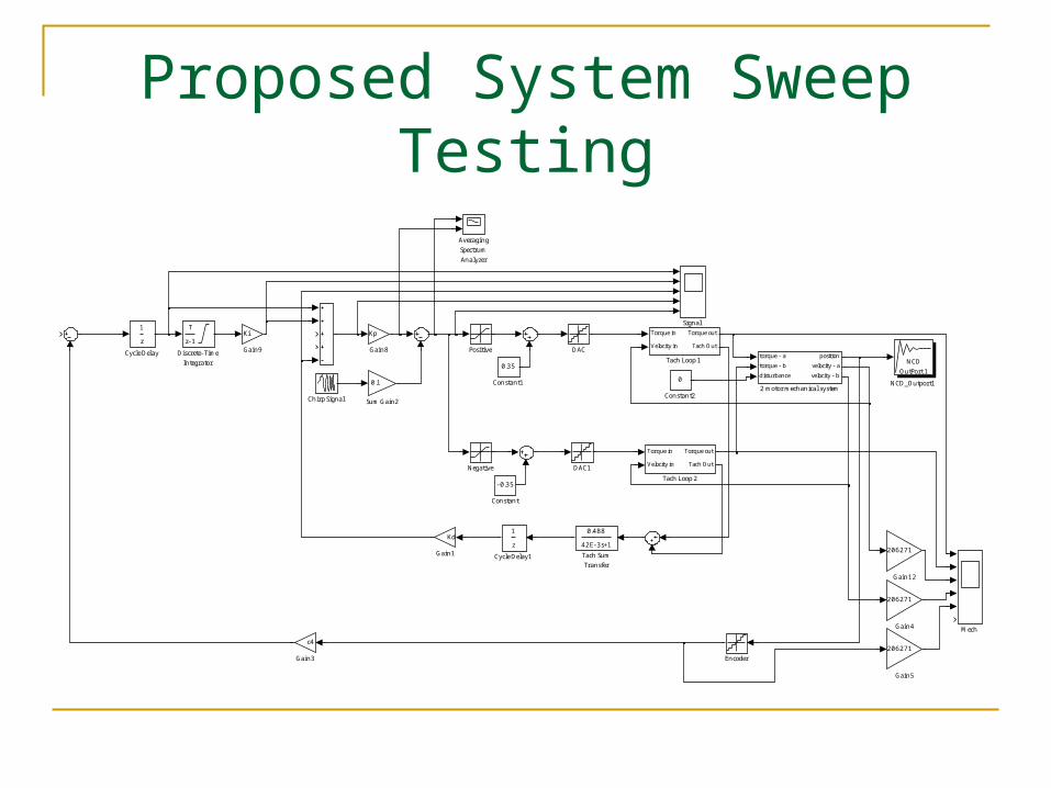
Proposed System Sweep Testing
NCD
OutPort 1
NCD_Outport1
0.488
42E- 3s+1
Tach Sum
Transfer
Torque in
Velocity in
Torque out
Tach Out
Tach Loop 2
Torque in
Velocity in
Torque out
Tach Out
Tach Loop 1
0.1
Sum Gain2
Signal
Positive
Negative
Mech
Ki
Gain9
Kp
Gain8
206271
Gain5
206271
Gain4
c4
Gain3
206271
Gain12
Kd
Gain1
Encoder
T
z- 1
Discrete- Time
Integrator
DAC1
DAC
z
1
Cycle Delay1
z
1
Cycle Delay
0
Constant2
0.35
Constant1
- 0.35
Constant
Chirp Signal
Averaging
Spectrum
Analyzer
torque - a
torque - b
disturbance
position
velocity - a
velocity - b
2 motor mechanical system
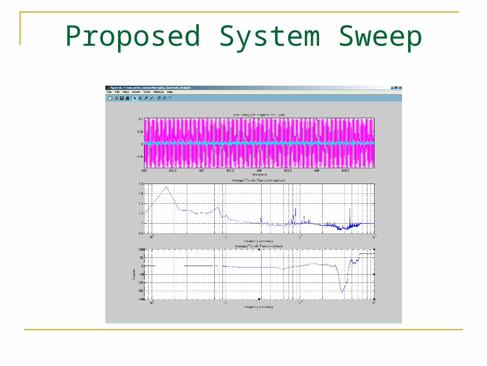
Proposed System Sweep
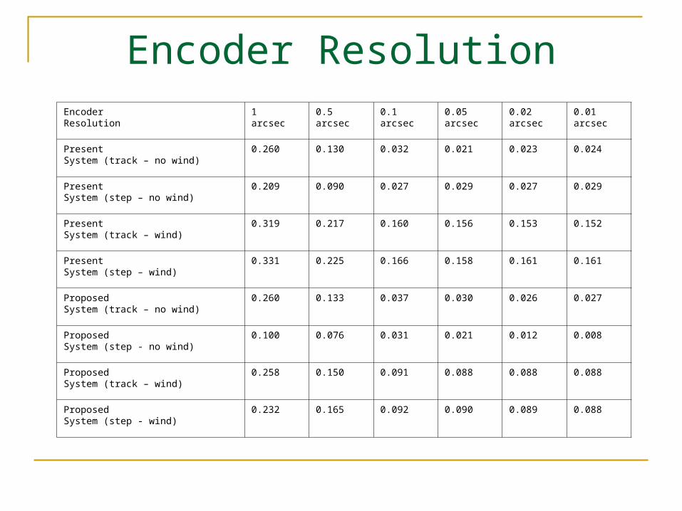
Encoder ResolutionEncoderResolution
1arcsec
0.5arcsec
0.1arcsec
0.05arcsec
0.02arcsec
0.01arcsec
PresentSystem (track – no wind)
0.260 0.130 0.032 0.021 0.023 0.024
PresentSystem (step – no wind)
0.209 0.090 0.027 0.029 0.027 0.029
PresentSystem (track – wind)
0.319 0.217 0.160 0.156 0.153 0.152
PresentSystem (step – wind)
0.331 0.225 0.166 0.158 0.161 0.161
ProposedSystem (track – no wind)
0.260 0.133 0.037 0.030 0.026 0.027
ProposedSystem (step - no wind)
0.100 0.076 0.031 0.021 0.012 0.008
ProposedSystem (track – wind)
0.258 0.150 0.091 0.088 0.088 0.088
ProposedSystem (step - wind)
0.232 0.165 0.092 0.090 0.089 0.088

Conclusion
PMAC will meet 0.1 arcsec resolution requirement
Present Encoder will meet resolution requirement
Present Tachometer loop is necessary Starting PID Values