Ser 600 Catalogue - Drive Technology
7
TORQUE LIMITER SERIES 600 Airjustor
Transcript of Ser 600 Catalogue - Drive Technology

TORQUE LIMITERSERIES 600
Airjustor

AUTOGARD SERIES 600
Quality and Autogard are synonymous with overload protection. The Company's reputation for high quality products is derived from over 40 years of design, innovation and production. Autogard products are manufactured to meet ISO 9001 using the latest machine tools and high quality materials.
D
A
E
F
C
B
2
The specifications contained within this brochure are correct at the time of going to print. Autogard is continually reviewing and updating the specifications on all its product ranges and therefore reserves the right to change any details.
The drive is transmitted through balls 'A' held in detents 'B' in opposing plates 'C' by adjustable air pressure acting on a large annular piston or a number of small pistons depending on the torque required.
The air cylinder / piston assembly 'D' is separated from the rotating drive plate / adapter 'E' and plates by two deep groove ball bearings 'F'. This allows air to be supplied radially for shaft to shaft and line shaft applications and gives a long maintenance free life.
As a Disengaging Clutch
When required to act as a disengaging clutch, the air is dumped at the press of a button, the balls roll out of the seats without skidding to disengage the drive, and the plates are held apart by spring pressure so that no drive is transmitted by the coupling. Two more ball bearings are provided between the hub and main drive plate / adapter to give a completely free running clutch.
As a Torque Limiter
The overload protection for the drive is provided by the same mechanism. The supply air pressure may be set in the range 1.35 - 5.4 Bar (20-80 psi) to give the precise overload torque requirement using a pressure regulator. This can be done manually during normal running to take account of changing loads, or automatically using a dual regulator system with a timer or other control. This allows high start torque to be accommodated before switching to a lower running torque. When the torque setting is exceeded, the balls begin to roll out of their seating, forcing plates apart against the air pressure. This motion operates a pneumatic limit switch which 'dumps' the air pressure, disengages the clutch and releasing the drive from the overloaded machine.
Re-engagement is effected in both cases simply by operating a Push Button Initiating Valve. Rotation of the drive at slow speed will then engage the clutch.
AUTOGARD SERIES 600
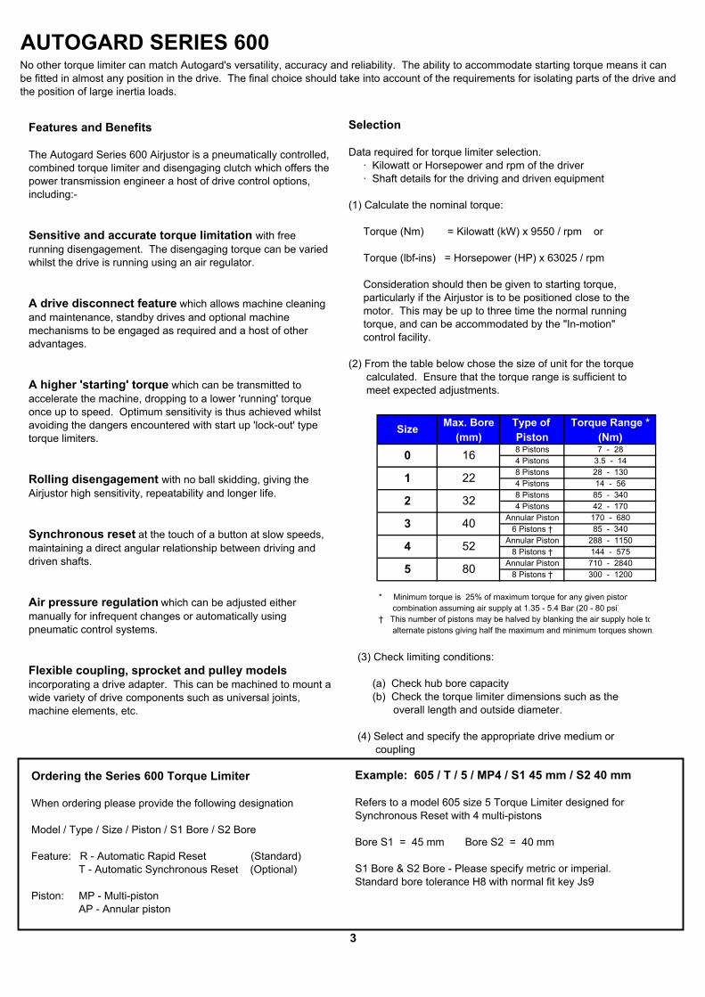
Max. Bore Type of Torque Range *(mm) Piston (Nm)
8 Pistons 7 - 284 Pistons 3.5 - 148 Pistons 28 - 1304 Pistons 14 - 568 Pistons 85 - 3404 Pistons 42 - 170
Annular Piston 170 - 6806 Pistons † 85 - 340
Annular Piston 288 - 11508 Pistons † 144 - 575
Annular Piston 710 - 28408 Pistons † 300 - 1200
* Minimum torque is 25% of maximum torque for any given piston combination assuming air supply at 1.35 - 5.4 Bar (20 - 80 psi)† This number of pistons may be halved by blanking the air supply hole to alternate pistons giving half the maximum and minimum torques shown.
Size
4
3
5
16
22
32
40
52
80
0
1
2
3
Example: 605 / T / 5 / MP4 / S1 45 mm / S2 40 mm
Refers to a model 605 size 5 Torque Limiter designed for Synchronous Reset with 4 multi-pistons
Bore S1 = 45 mm Bore S2 = 40 mm
S1 Bore & S2 Bore - Please specify metric or imperial.Standard bore tolerance H8 with normal fit key Js9
Ordering the Series 600 Torque Limiter
When ordering please provide the following designation
Model / Type / Size / Piston / S1 Bore / S2 Bore
Feature: R - Automatic Rapid Reset (Standard) T - Automatic Synchronous Reset (Optional)
Piston: MP - Multi-piston AP - Annular piston
No other torque limiter can match Autogard's versatility, accuracy and reliability. The ability to accommodate starting torque means it can be fitted in almost any position in the drive. The final choice should take into account of the requirements for isolating parts of the drive and the position of large inertia loads.
Features and Benefits
The Autogard Series 600 Airjustor is a pneumatically controlled, combined torque limiter and disengaging clutch which offers the power transmission engineer a host of drive control options, including:-
Sensitive and accurate torque limitation with free running disengagement. The disengaging torque can be varied whilst the drive is running using an air regulator.
A drive disconnect feature which allows machine cleaning and maintenance, standby drives and optional machine mechanisms to be engaged as required and a host of other advantages.
A higher 'starting' torque which can be transmitted to accelerate the machine, dropping to a lower 'running' torque once up to speed. Optimum sensitivity is thus achieved whilst avoiding the dangers encountered with start up 'lock-out' type torque limiters.
Rolling disengagement with no ball skidding, giving the Airjustor high sensitivity, repeatability and longer life.
Synchronous reset at the touch of a button at slow speeds, maintaining a direct angular relationship between driving and driven shafts.
Air pressure regulation which can be adjusted either manually for infrequent changes or automatically using pneumatic control systems.
Flexible coupling, sprocket and pulley models incorporating a drive adapter. This can be machined to mount a wide variety of drive components such as universal joints, machine elements, etc.
Selection
Data required for torque limiter selection. · Kilowatt or Horsepower and rpm of the driver · Shaft details for the driving and driven equipment
(1) Calculate the nominal torque:
Torque (Nm) = Kilowatt (kW) x 9550 / rpm or
Torque (lbf-ins) = Horsepower (HP) x 63025 / rpm
Consideration should then be given to starting torque, particularly if the Airjustor is to be positioned close to the motor. This may be up to three time the normal running torque, and can be accommodated by the "In-motion" control facility.
(2) From the table below chose the size of unit for the torque calculated. Ensure that the torque range is sufficient to meet expected adjustments.
(3) Check limiting conditions:
(a) Check hub bore capacity (b) Check the torque limiter dimensions such as the overall length and outside diameter.
(4) Select and specify the appropriate drive medium or coupling

AUTOGARD SERIES 600MODEL 602For use with sprockets, pulleys or gears.
Technical Data
1) For higher torque applications please consult Autogard.2) Higher speeds may be allowed under certain conditions. Please consult Autogard3) Weights and moments of inertia apply to maximum bore (S1).
Dimensional Data - mm
3/81/25/83/4
1
4) For sizes 2 and above when using maximum bores, use rectangular parallel keys5) Tolerance for diameter M is k76) Movement on disengagement7) The diameter quoted is to the bottom of a V pulley groove or the ID of the flange on a timing pulley
75160 190
16
152 245
160 210 230
235140 180 210
67.7
56
APMP
PCD
GHJLMN
W
Standard
20
195
Torque Nm
Speed rpmWeight Kg
Size
E
3 - M8 3 - M86 - 106 - 8
3 - M46 - 46 - 3
3 - M5
129
17 22 42 40
4
Max. Bore S1
B
6 - 5 6 - 6
Smallest Sprocket(No. of teeth) ins. pitch
ins. pitch
MP AP MP
2227
-
2.43 - M3
110
AP
34
6.04.0
753040 25
2 10.3
60 82
33
18095 140
100
62
1 2
10005.4
0.003
ins. pitch -
ins. pitchins. pitch
262017-
200
43
6.0
125
100
3 - M6
41 50 6231 3826 31 39
17 21 25
-6049 53
-
22 27 33-
Smallest Pulley Diameter (mm) 68 94 112 140 180
65
32 34228 248
41 44
48
310
55 70 10510 12
80 78 88
0.25 0.301
7.7 8.5
184 255
220 305
59
80
16.3 27.8
168 230159
3
15948 46
0.024
150 71043 170 72 288
AP340 680 575 1150 1200 2840
MP AP MPSize 0 4 52 31
MP AP
0.001
0
D17A
Mass Moment of inertia Kgm2
MountingHole Pattern
116
U 47
X 30
52
No. & Size of HolesNo. & Size of Dowels
146 165
15
32 805240
4510
143
70 85
16 22
13465 9870 102
44 55 70
25 358 8
0.064
4 5
Min 421000 Max
143.5
0.008
500 500
Max 28 130 340
500 500
75 5332 37
125
135 130
53 47
L
PCDG dia
HJ
A
N dia
X
Tapped Holes for Anti-Rotation AttachmentSize 0 - 1 x M3Sizes 1 to 4 - 2 x M6 (Except Size 3 MP 2 x M8)Size 5 - 2 x M8

AUTOGARD SERIES 600MODEL 605Design including the Autogard Autoflex EB torsionally rigid metal membrane coupling for angular misalignment. The AutogardAutoflex ES coupling can also be supplied which accommodates angular and parallel offset misalignment.
Technical Data
1) For higher torque applications please consult Autogard.2) Higher speeds may be allowed under certain conditions. Please consult Autogard3) Weights and moments of inertia apply to maximum bores (S1 & S2).
Dimensional Data - mm
4) For maximum bores greater than 25 mm use rectangular parallel keys.5) Movement on disengagement
5
Min
0.74½
0.49
331
8045
4090
340 68043 170
340
0.608
½
59 59
72
110
55
22 42
1200 2840575
4 / 150HVII 5 / 480HVII2 / 70HVIIMP AP
3 / 150HVIIMP APAPMP
75
200123
58190
8.8133 170
91180
160 190
32 37 75 5395 133 159100
6 6 7.7 8.52.4 4
140
B
9.4
30 40
UV
R
95
220 305
235
8.8170 230
15
123
129134 159
225
78
Size 0 / 8HVII
3017
Max. Bore S1Max. Bore S2
A
Size 0 / 8HVII
Misalignments Angular ( o )
Kg1000
Mass Moment of inertia Kgm2
Axial (mm) Max Coupling
Weight
3.513014
28
1 / 35HVII
Torque
Speed
Nm
rpm 1000
Max
Max
0.00827.2
0.0190.56
8.7
½1.0
½0.3
½0.74
3.40.0016
½
1150
0.059 0.11115.7500
40.5
42 288 150 710
0.602
245
5 / 480HVIIMP AP
80
255
110
2 / 70HVII
5022 32
66
1 / 35HVII
16
130
142 162 305
75270
80
454150
9.4
MP AP3 / 150HVII
135
90
152 143 168 168184
25X 53 47
12575
16
6246
110
71
98102
75
57 76 89
1770
44
47
7.495
65
46
23 33167 195
70 88230
T1T2 33
116
DEJK
44LM
80
NP (nominal gap)
500 500 500
56
5240
4 / 150HVIIMP AP
48
N dia
P
Tapped Holes for Anti-Rotation AttachmentSize 0 - 1 x M3Sizes 1 to 4 - 2 x M6 (Except Size 3 MP 2 x M8)Size 5 - 2 x M8

AUTOGARD SERIES 600MODEL 606NDesign including a torsionally soft flexible coupling for parallel and angular misalignment
Technical Data
1) For higher torque applications please consult Autogard.2) Higher speeds may be allowed under certain conditions. Please consult Autogard3) Weights and moments of inertia apply to maximum bores (S1 & S2).
Dimensional Data - mm
4) For maximum bores greater than 25 mm use rectangular parallel keys.5) Movement on disengagement
0.434
0.648
125 160 200 2503
129
500
Max CouplingMisalignments
112
4 50.28 0.33
0.152
11501501200 2840
710288
Size 5 / 250MP AP
4 / 200MP AP575
Axial (mm) Parallel (mm)
0.09
Torque
Angular ( o )
72500
0.13
2.90.0011
0.182
0.009
70 102
48241617
6 7.7 8.5
4 4 5.5
30560 80 100
6
65 85 100
159 184 255
190 235
235
2.4 4
- 78
3
11620 40
68 1103
140 202
65 9855
134
55
5 / 2500 / 68 1 / 110 2 / 125 4 / 2003 / 160AP MP
0.1
0.65548.4
2
0.1
15.60.051
0.20.1 0.1
0 / 68 2 / 125 3 / 160
3.5130 34014
2843 170
1 / 110MP AP
42340 680 Max
Max Min
Nm
Size
0.019Mass Moment of inertia Kgm2
0.09
24.9Speed rpm
Kg1000 1000
9.9500 500
Weight
MP AP16 22 32 40 52 80
MP AP
80152 143 168
70 80 78- 13 19 21
162
90448
108 140 165280 340
180 200P (nominal gap)
Max. Bore S1Max. Bore S2
DEJKLM
30 40
RT1T2
142
V 57 76
50190
B
N 95 140
U 47 62
X95 133 159
7589
88168
220 305
135 13033 40
230 245
6
48 46 56
44
47 75
100 160
40
53
A 17 22 42
25 32 37 53
125
N dia
P
Tapped Holes for Anti-Rotation AttachmentSize 0 - 1 x M3Sizes 1 to 4 - 2 x M6 (Except Size 3 MP 2 x M8)Size 5 - 2 x M8

AUTOGARD SERIES 600GENERAL INFORMATIONGraphs plotting torque (Nm) against air pressure for each size.
7
The Autogard Torque Limiter is a reliable unit, built to high standards of workmanship. Similar to all mechanical devices, each application must be considered on its own merits with reference to safety (i.e. lifting equipment, explosive conditions, etc.). As a rotating component, adequate guarding must be provided, in accordance with local codes. Autogard staff are always available to discuss particular applications.
Maintenance
The Autogard torque limiter uses journal and needle thrust bearings. The latter are packed with grease on assembly as are the driving balls. Under reasonably clean conditions the unit will operate with a minimum of maintenance and re-lubrication. The frequency of maintenance is dependant on many operating factors, but in adverse conditions please consult Autogard.
Protective Finish
The standard finish provides a high level of corrosive resistance. Units can be supplied with a suitable alternative finish for special machinery requirements, or for adverse environmental conditions. Please consult Autogard to discuss special requirements.
Pneumatic Controls.
This suggested system permits simple torque adjustment of the Airjustor. The torque may be varied from 25% of the maximum torque to maximum torque of the piston configuration used (that is 1.35 - 5.4 Bar or 20 - 80 psi). This can be accomplished either when the drive is stationary or 'In-motion'
The use of a quick exhaust valve is strongly recommended to aid disengagement.
General Safety