Catalogue Servomotors - BERGER LAHR Servis...
32
Catalogue Servomotors
Transcript of Catalogue Servomotors - BERGER LAHR Servis...
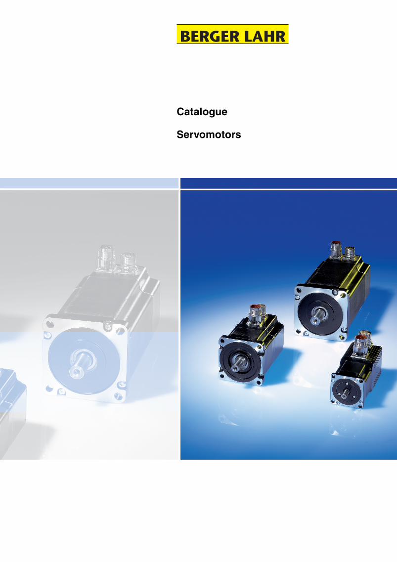
Catalogue
Servomotors

Berger Lahr Catalogue Servomotors 1
Servomotors Table of contents
SER servomotors
Product description . . . . . . . . . . . . . . . . . . . . . . . . . . . . . . . . . . . . . . 2
SER 36•
Technical data . . . . . . . . . . . . . . . . . . . . . . . . . . . . . . . . . . . . . . . . 4
Dimensional drawings . . . . . . . . . . . . . . . . . . . . . . . . . . . . . . . . . . 7
Type code . . . . . . . . . . . . . . . . . . . . . . . . . . . . . . . . . . . . . . . . . . . . 8
SER 39•
Technical data . . . . . . . . . . . . . . . . . . . . . . . . . . . . . . . . . . . . . . . . 9
Dimensional drawings . . . . . . . . . . . . . . . . . . . . . . . . . . . . . . . . . 12
Type code . . . . . . . . . . . . . . . . . . . . . . . . . . . . . . . . . . . . . . . . . . . 13
SER 311•
Technical data . . . . . . . . . . . . . . . . . . . . . . . . . . . . . . . . . . . . . . . 14
Dimensional drawings . . . . . . . . . . . . . . . . . . . . . . . . . . . . . . . . . 17
Type code . . . . . . . . . . . . . . . . . . . . . . . . . . . . . . . . . . . . . . . . . . . 18
Options
Holding brake . . . . . . . . . . . . . . . . . . . . . . . . . . . . . . . . . . . . . . . . . 20
Position capture . . . . . . . . . . . . . . . . . . . . . . . . . . . . . . . . . . . . . . . 21
Gearing for SER servomotors . . . . . . . . . . . . . . . . . . . . . . . . . . . . 23
Appendix
Conversion tables . . . . . . . . . . . . . . . . . . . . . . . . . . . . . . . . . . . . . . 27
2 Catalogue Servomotors Berger Lahr
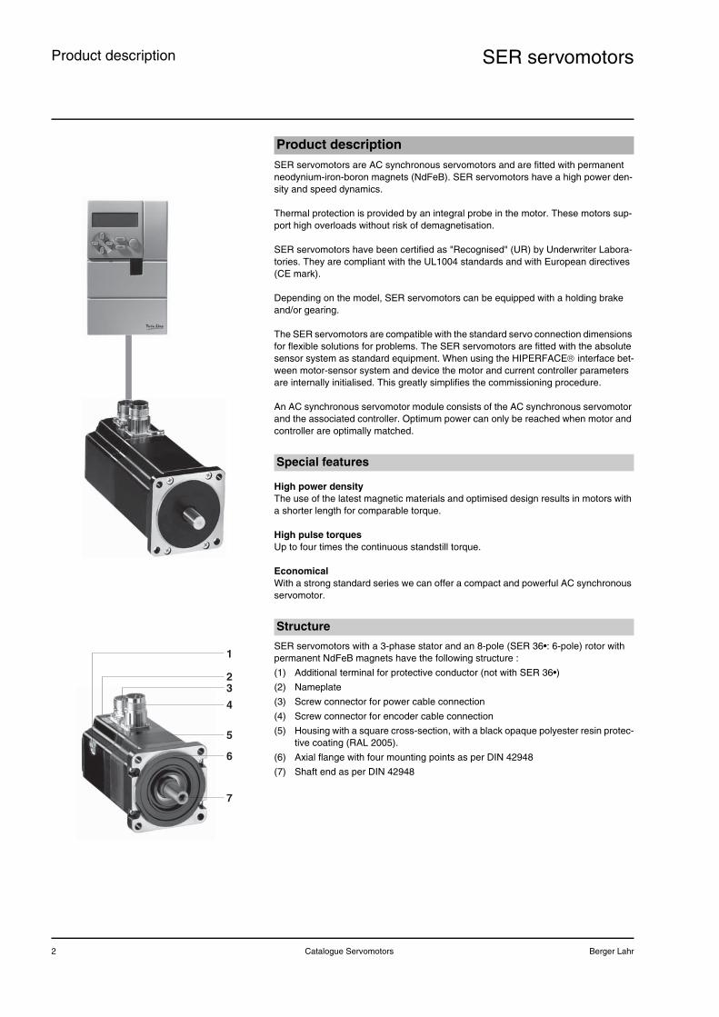
SER servomotorsProduct description
SER servomotors are AC synchronous servomotors and are fitted with permanent neodynium-iron-boron magnets (NdFeB). SER servomotors have a high power den-sity and speed dynamics.
Thermal protection is provided by an integral probe in the motor. These motors sup-port high overloads without risk of demagnetisation.
SER servomotors have been certified as "Recognised" (UR) by Underwriter Labora-tories. They are compliant with the UL1004 standards and with European directives (CE mark).
Depending on the model, SER servomotors can be equipped with a holding brake and/or gearing.
The SER servomotors are compatible with the standard servo connection dimensions for flexible solutions for problems. The SER servomotors are fitted with the absolute sensor system as standard equipment. When using the HIPERFACE® interface bet-ween motor-sensor system and device the motor and current controller parameters are internally initialised. This greatly simplifies the commissioning procedure.
An AC synchronous servomotor module consists of the AC synchronous servomotor and the associated controller. Optimum power can only be reached when motor and controller are optimally matched.
High power densityThe use of the latest magnetic materials and optimised design results in motors with a shorter length for comparable torque.
High pulse torquesUp to four times the continuous standstill torque.
EconomicalWith a strong standard series we can offer a compact and powerful AC synchronous servomotor.
SER servomotors with a 3-phase stator and an 8-pole (SER 36•: 6-pole) rotor with permanent NdFeB magnets have the following structure :
(1) Additional terminal for protective conductor (not with SER 36•)
(2) Nameplate
(3) Screw connector for power cable connection
(4) Screw connector for encoder cable connection
(5) Housing with a square cross-section, with a black opaque polyester resin protec-tive coating (RAL 2005).
(6) Axial flange with four mounting points as per DIN 42948
(7) Shaft end as per DIN 42948
Product description
Special features
Structure
1
23
4
6
5
7
Berger Lahr Catalogue Servomotors 3
SER servomotors Product description
Note: For combination options see type code
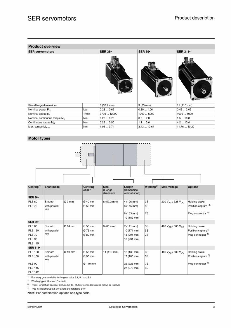
Product overviewSER servomotors SER 36• SER 39• SER 311•
Size (flange dimension) 6 (57.2 mm) 9 (85 mm) 11 (110 mm)
Nominal power PN kW 0.28 ... 0.62 0.30 ... 1.06 0.42 ... 2.09
Nominal speed nN 1/min 3700 ... 12000 1200 ... 6000 1000 ... 6000
Nominal continuous torque MN Nm 0.26 ... 0.78 0.6 ... 2.8 1.5 ... 10.8
Continuous torque M0 Nm 0.29 ... 0.90 1.1 ... 3.6 4.2 ... 13.4
Max. torque Mmax Nm 1.03 ... 3.74 3.43 ... 12.67 11.76 ... 40.20
Motor types
Gearing 1) Shaft model Centring collar
Size(Flange dimension)
Length(Dimension without shaft)
Winding 2) Max. voltage Options
SER 36•
PLE 60 Smooth Ø 9 mm Ø 40 mm 6 (57.2 mm) 4 (126 mm) 3S 230 VAC / 325 VDC Holding brake
PLS 70 with parallel key
Ø 50 mm 6 (145 mm) 5S Position capture 3)
8 (163 mm) 7S Plug connector 4)
10 (182 mm)
SER 39•
PLE 80 Smooth Ø 14 mm Ø 50 mm 9 (85 mm) 7 (141 mm) 3S 480 VAC / 680 VDC Holding brake
PLE 120 with parallel key
Ø 73 mm 10 (171 mm) 5S Position capture3)
PLS 70 Ø 80 mm 13 (201 mm) 7S Plug connector 4)
PLS 90 16 (231 mm)
PLS 115
SER 311•
PLE 120 Smooth Ø 19 mm Ø 56 mm 11 (110 mm) 12 (132 mm) 3S 480 VAC / 680 VDC Holding brake
PLE 160 with parallel key
Ø 95 mm 17 (180 mm) 5S Position capture 3)
PLS 90 Ø 110 mm 22 (228 mm) 7S Plug connector 4)
PLS 115 27 (276 mm) 5D
PLS 142
1) Planetary gear available in the gear ratios 3:1, 5:1 and 8:12) Winding types: S = star; D = delta3) Types: Singleturn encoder SinCos (SRS), Multiturn encoder SinCos (SRM) or resolver4) Type 1: straight; type 2: 90° angle and rotatable 310°
4 Catalogue Servomotors Berger Lahr
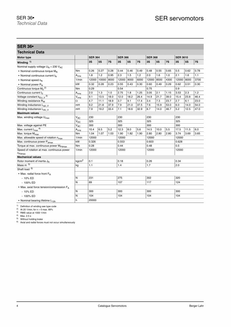
SER servomotorsSER 36•Technical Data
SER 36•Technical DataMotor type SER 364 SER 366 SER 368 SER 3610
Winding 1) 3S 5S 7S 3S 5S 7S 3S 5S 7S 3S 5S 7S
Nominal supply voltage UN = 230 VAC
• Nominal continuous torque MN Nm 0.26 0.27 0.28 0.44 0.46 0.49 0.48 0.55 0.65 0.5 0.62 0.78
• Nominal continuous current IN Arms 1.8 1.2 0.95 2.3 1.5 1.2 2.0 1.6 1.0 2.1 1.6 1.1
• Nominal speed nN 1/min 12000 10000 8000 12000 9000 6000 12000 8500 4300 12000 8000 3700
• Nominal power PN kW 0.32 0.28 0.23 0.55 0.43 0.30 0.60 0.49 0.29 0.62 0.51 0.30
Continuous torque M02) Nm 0.29 0.54 0.75 0.9
Continuous current I0 Arms 2.0 1.3 1.0 2.75 1.8 1.25 3.05 2.1 1.15 3.53 2.3 1.2
Voltage constant kEU_V3) Vrms 9.1 13.5 18.0 12.0 18.2 26.4 14.9 21.7 39.0 15.4 23.8 46.4
Winding resistance RW Ω 4.7 11.1 18.9 3.7 9.1 17.4 3.4 7.3 23.7 2.7 6.1 23.0
Winding inductance LqU_V mH 9.2 21.8 37.9 7.9 21.0 37.5 7.6 15.9 53.0 6.0 14.0 54.0
Winding inductance LdU_V mH 7.9 19.2 33.4 7.1 18.6 32.9 6.7 14.0 46.7 5.2 12.5 47.0
Maximum values
Max. winding voltage Umax VAC 230 230 230 230
VDC 325 325 325 325
Max. voltage against PE VAC 300 300 300 300
Max. current Imax4) Arms 10.4 6.5 5.2 12.3 8.0 5.6 14.5 10.0 5.5 17.5 11.5 6.0
Max. torque Mmax Nm 1.04 1.07 1.03 1.90 1.82 1.90 2.80 2.80 2.80 3.74 3.69 3.65
Max. allowable speed of rotation nmax 1/min 12000 12000 12000 12000
Max. continuous power Pdmax kW 0.326 0.553 0.603 0.628
Torque at max. continuous power MPdmax Nm 0.28 0.44 0.48 0.5
Speed of rotation at max. continuous power nPdmax
1/min 12000 12000 12000 12000
Mechanical values
Rotor moment of inertia JR kgcm2 0.1 0.18 0.26 0.34
Mass m 5) kg 1.1 1.4 1.7 2.0
Shaft load 6)
• Max. radial force front FR
- 10% ED N 231 275 302 320
- 100% ED N 89 107 117 124
• Max. axial force tension/compression FA
- 10% ED N 300 300 300 300
- 100% ED N 104 104 104 104
• Nominal bearing lifetime L10h h 20000
1) Definition of winding see type code2) At 20 1/min; for n = 0 max. 89%3) RMS value at 1000 1/min4) Max. 2.5 s 5) Without holding brake6) Axial and radial forces must not occur simultaneously
Berger Lahr Catalogue Servomotors 5
SER servomotors SER 36•Technical Data
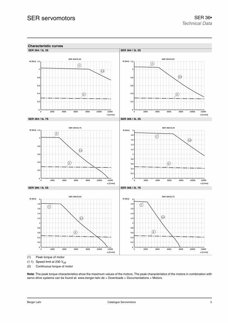
(1) Peak torque of motor
(1.1) Speed limit at 230 Veff
(2) Continuous torque of motor
Note: The peak torque characteristics show the maximum values of the motors. The peak characteristics of the motors in combination withservo drive systems can be found at: www.berger-lahr.de > Downloads > Documentations > Motors.
Characteristic curvesSER 364 / 3L 3S SER 364 / 3L 5S
SER 364 / 3L 7S SER 366 / 3L 3S
SER 366 / 3L 5S SER 366 / 3L 7S
SER 364/3L3S
020000 4000 6000 8000 10000 12000
n [1/min]
1,2M [Nm]
1.1
2
1
1
0,8
0,6
0,4
0,2
SER 364/3L5S
020000 4000 6000 8000 10000 12000
n [1/min]
1,2M [Nm]
1.1
2
1
1
0,8
0,6
0,4
0,2
SER 364/3L7S
020000 4000 6000 8000 10000 12000
n [1/min]
1,2M [Nm]
1.1
2
1
1
0,8
0,6
0,4
0,2
1
0,6
0,2
SER 366/3L3S
020000 4000 6000 8000 10000 12000
n [1/min]
M [Nm]
1.1
2
1,8
1,6
1,4
1,2
0,8
0,4
1
2
1
0,6
0,2
SER 366/3L5S
020000 4000 6000 8000 10000 12000
n [1/min]
M [Nm] 2
1,8
1,6
1,4
1,2
0,8
0,4
1
1.1
2
1
0,6
0,2
SER 366/3L7S
020000 4000 6000 8000 10000 12000
n [1/min]
M [Nm] 2
1,8
1,6
1,4
1,2
0,8
0,4
1
1.1
2
6 Catalogue Servomotors Berger Lahr
SER servomotorsSER 36•Technical Data
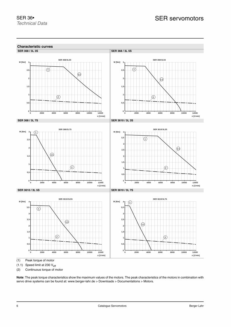
(1) Peak torque of motor
(1.1) Speed limit at 230 Veff
(2) Continuous torque of motor
Note: The peak torque characteristics show the maximum values of the motors. The peak characteristics of the motors in combination withservo drive systems can be found at: www.berger-lahr.de > Downloads > Documentations > Motors.
Characteristic curvesSER 368 / 3L 3S SER 368 / 3L 5S
SER 368 / 3L 7S SER 3610 / 3L 3S
SER 3610 / 3L 5S SER 3610 / 3L 7S
SER 368/3L3S
020000 4000 6000 8000 10000 12000
n [1/min]
2,5
M [Nm]
1.1
2
1
0,5
3
2
1,5
1
SER 368/3L5S
020000 4000 6000 8000 10000 12000
n [1/min]
2,5
M [Nm]
1.1
2
1
0,5
3
2
1,5
1
SER 368/3L7S
020000 4000 6000 8000 10000 12000
n [1/min]
2,5
M [Nm]
1.1
2
1
0,5
3
2
1,5
1
1
1,5
2
0,5
SER 3610/3L3S
020000 4000 6000 8000 10000 12000
n [1/min]
M [Nm] 4
2,5
1
3
3,5
2
1.1
1
1,5
2
0,5
SER 3610/3L5S
020000 4000 6000 8000 10000 12000
n [1/min]
M [Nm] 4
2,5
1
3
3,5
2
1.1
1
1,5
2
0,5
SER 3610/3L7S
020000 4000 6000 8000 10000 12000
n [1/min]
M [Nm] 4
2,5
1
3
3,5
2
1.1
Berger Lahr Catalogue Servomotors 7
SER servomotors SER 36•Dimensional drawings
Dimensional drawing SER 36•
Ambient conditionsOperating / ambient temperature without power reduction
°C 20 ... 40
Installation height without power reduction m above MSL
1000
Transport and storage temperature °C -25 ... +70
Relative humidity % 15 … 85 (non-condensing)
Vibration magnitude in operation as per DIN EN 60034-14
A
Vibration strain as per DIN EN 60068-2-6
• Acceleration amplitude m/s² 20
• Frequency range Hz 10 ... 500
• Number of cycles 10
Degree of protection as per DIN EN 60034-5
• Shaft exit frontwithout shaft seal ring
IP 41
• Shaft exit frontwith shaft seal ring
IP 56 1)
• Motor housing IP 56
Thermal class as per DIN EN 60034-1 155 (F)
Shaft wobble and run-out accuracy as per DIN 42955 N (IEC 60072-1)
Max. rotary acceleration rad/s2 200000
1) Speed restriction by shaft seal ring at 6000 1/min; with mounting position IM V3 (drive shaft vertical, shaft end up) only degree of protection IP 41 is guaranteed.
Dimensional drawings
SER 368
SER 366
SER 364
SER 3610
50
50
50
50
40
40
40
40
Ø9
j6
20
4
L
52
4931
Optionca. 100°
ca. 210°Option
Encoder 12-pinMotor 8-pin
ca. 100°Option
Option ca. 210°
DIN 332 - DS M3
3x3x12 DIN 6885Fitting spring AOption
5.8
ØD
-0.0
5
21.7
1.6 Ø5.2
R5
57.2
47.242.4
34.8
Length Lwithout brake
Length Lwith brake
ØDStandard
ØDOption
162.8
181.3
144.3
125.8
202.3
220.8
183.8
165.3
8 Catalogue Servomotors Berger Lahr
SER servomotorsSER 36•Type code
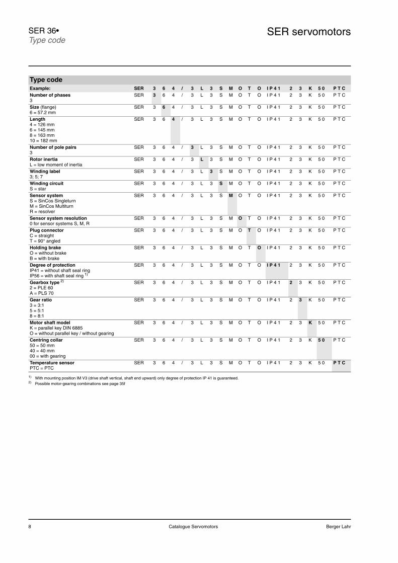
Type codeExample: SER 3 6 4 / 3 L 3 S M O T O I P 4 1 2 3 K 5 0 P T CNumber of phases3
SER 3 6 4 / 3 L 3 S M O T O I P 4 1 2 3 K 5 0 P T C
Size (flange) 6 = 57.2 mm
SER 3 6 4 / 3 L 3 S M O T O I P 4 1 2 3 K 5 0 P T C
Length4 = 126 mm6 = 145 mm8 = 163 mm10 = 182 mm
SER 3 6 4 / 3 L 3 S M O T O I P 4 1 2 3 K 5 0 P T C
Number of pole pairs3
SER 3 6 4 / 3 L 3 S M O T O I P 4 1 2 3 K 5 0 P T C
Rotor inertiaL = low moment of inertia
SER 3 6 4 / 3 L 3 S M O T O I P 4 1 2 3 K 5 0 P T C
Winding label3; 5; 7
SER 3 6 4 / 3 L 3 S M O T O I P 4 1 2 3 K 5 0 P T C
Winding circuitS = star
SER 3 6 4 / 3 L 3 S M O T O I P 4 1 2 3 K 5 0 P T C
Sensor systemS = SinCos SingleturnM = SinCos MultiturnR = resolver
SER 3 6 4 / 3 L 3 S M O T O I P 4 1 2 3 K 5 0 P T C
Sensor system resolution0 for sensor systems S, M, R
SER 3 6 4 / 3 L 3 S M O T O I P 4 1 2 3 K 5 0 P T C
Plug connectorC = straightT = 90° angled
SER 3 6 4 / 3 L 3 S M O T O I P 4 1 2 3 K 5 0 P T C
Holding brakeO = without brakeB = with brake
SER 3 6 4 / 3 L 3 S M O T O I P 4 1 2 3 K 5 0 P T C
Degree of protectionIP41 = without shaft seal ringIP56 = with shaft seal ring 1)
SER 3 6 4 / 3 L 3 S M O T O I P 4 1 2 3 K 5 0 P T C
Gearbox type 2)
2 = PLE 60A = PLS 70
SER 3 6 4 / 3 L 3 S M O T O I P 4 1 2 3 K 5 0 P T C
Gear ratio3 = 3:15 = 5:18 = 8:1
SER 3 6 4 / 3 L 3 S M O T O I P 4 1 2 3 K 5 0 P T C
Motor shaft modelK = parallel key DIN 6885O = without parallel key / without gearing
SER 3 6 4 / 3 L 3 S M O T O I P 4 1 2 3 K 5 0 P T C
Centring collar50 = 50 mm40 = 40 mm00 = with gearing
SER 3 6 4 / 3 L 3 S M O T O I P 4 1 2 3 K 5 0 P T C
Temperature sensorPTC = PTC
SER 3 6 4 / 3 L 3 S M O T O I P 4 1 2 3 K 5 0 P T C
1) With mounting position IM V3 (drive shaft vertical, shaft end upward) only degree of protection IP 41 is guaranteed.2) Possible motor-gearing combinations see page 35f
Berger Lahr Catalogue Servomotors 9
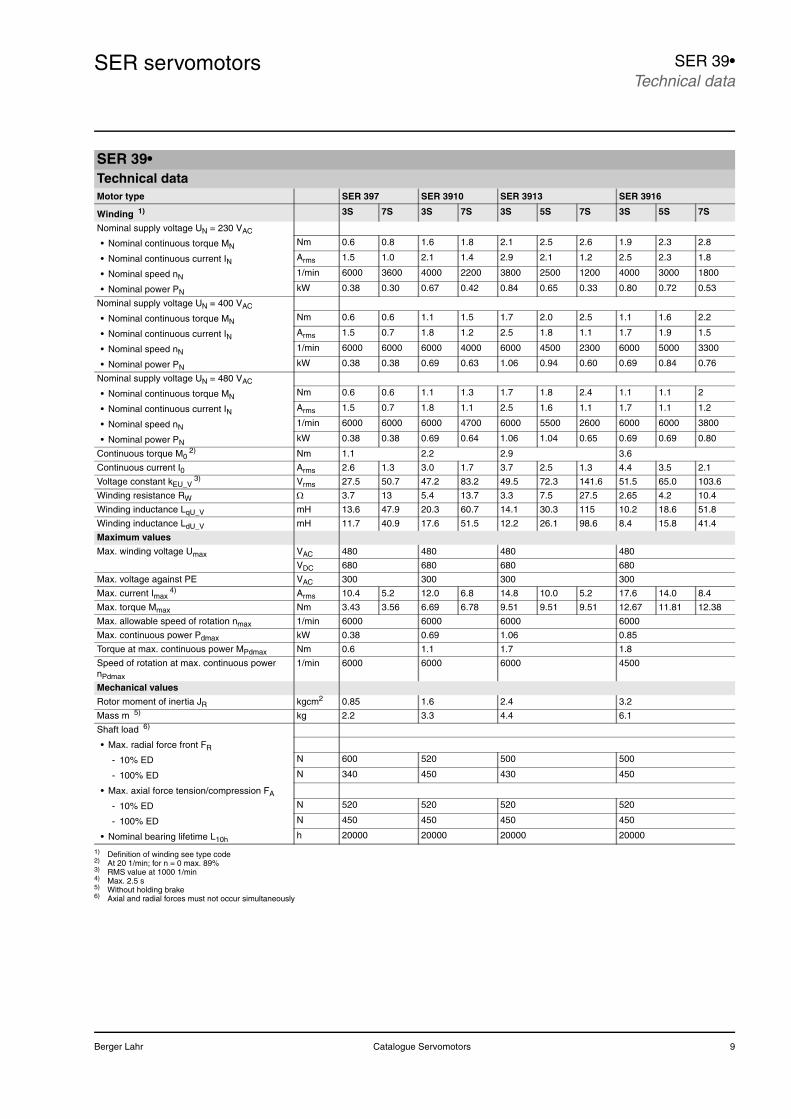
SER servomotors SER 39•Technical data
SER 39•Technical dataMotor type SER 397 SER 3910 SER 3913 SER 3916
Winding 1) 3S 7S 3S 7S 3S 5S 7S 3S 5S 7S
Nominal supply voltage UN = 230 VAC
• Nominal continuous torque MN Nm 0.6 0.8 1.6 1.8 2.1 2.5 2.6 1.9 2.3 2.8
• Nominal continuous current IN Arms 1.5 1.0 2.1 1.4 2.9 2.1 1.2 2.5 2.3 1.8
• Nominal speed nN 1/min 6000 3600 4000 2200 3800 2500 1200 4000 3000 1800
• Nominal power PN kW 0.38 0.30 0.67 0.42 0.84 0.65 0.33 0.80 0.72 0.53
Nominal supply voltage UN = 400 VAC
• Nominal continuous torque MN Nm 0.6 0.6 1.1 1.5 1.7 2.0 2.5 1.1 1.6 2.2
• Nominal continuous current IN Arms 1.5 0.7 1.8 1.2 2.5 1.8 1.1 1.7 1.9 1.5
• Nominal speed nN 1/min 6000 6000 6000 4000 6000 4500 2300 6000 5000 3300
• Nominal power PN kW 0.38 0.38 0.69 0.63 1.06 0.94 0.60 0.69 0.84 0.76
Nominal supply voltage UN = 480 VAC
• Nominal continuous torque MN Nm 0.6 0.6 1.1 1.3 1.7 1.8 2.4 1.1 1.1 2
• Nominal continuous current IN Arms 1.5 0.7 1.8 1.1 2.5 1.6 1.1 1.7 1.1 1.2
• Nominal speed nN 1/min 6000 6000 6000 4700 6000 5500 2600 6000 6000 3800
• Nominal power PN kW 0.38 0.38 0.69 0.64 1.06 1.04 0.65 0.69 0.69 0.80
Continuous torque M02) Nm 1.1 2.2 2.9 3.6
Continuous current I0 Arms 2.6 1.3 3.0 1.7 3.7 2.5 1.3 4.4 3.5 2.1
Voltage constant kEU_V3) Vrms 27.5 50.7 47.2 83.2 49.5 72.3 141.6 51.5 65.0 103.6
Winding resistance RW Ω 3.7 13 5.4 13.7 3.3 7.5 27.5 2.65 4.2 10.4
Winding inductance LqU_V mH 13.6 47.9 20.3 60.7 14.1 30.3 115 10.2 18.6 51.8
Winding inductance LdU_V mH 11.7 40.9 17.6 51.5 12.2 26.1 98.6 8.4 15.8 41.4
Maximum values
Max. winding voltage Umax VAC 480 480 480 480
VDC 680 680 680 680
Max. voltage against PE VAC 300 300 300 300
Max. current Imax4) Arms 10.4 5.2 12.0 6.8 14.8 10.0 5.2 17.6 14.0 8.4
Max. torque Mmax Nm 3.43 3.56 6.69 6.78 9.51 9.51 9.51 12.67 11.81 12.38
Max. allowable speed of rotation nmax 1/min 6000 6000 6000 6000
Max. continuous power Pdmax kW 0.38 0.69 1.06 0.85
Torque at max. continuous power MPdmax Nm 0.6 1.1 1.7 1.8
Speed of rotation at max. continuous power nPdmax
1/min 6000 6000 6000 4500
Mechanical values
Rotor moment of inertia JR kgcm2 0.85 1.6 2.4 3.2
Mass m 5) kg 2.2 3.3 4.4 6.1
Shaft load 6)
• Max. radial force front FR
- 10% ED N 600 520 500 500
- 100% ED N 340 450 430 450
• Max. axial force tension/compression FA
- 10% ED N 520 520 520 520
- 100% ED N 450 450 450 450
• Nominal bearing lifetime L10h h 20000 20000 20000 20000
1) Definition of winding see type code2) At 20 1/min; for n = 0 max. 89%3) RMS value at 1000 1/min4) Max. 2.5 s 5) Without holding brake6) Axial and radial forces must not occur simultaneously
10 Catalogue Servomotors Berger Lahr
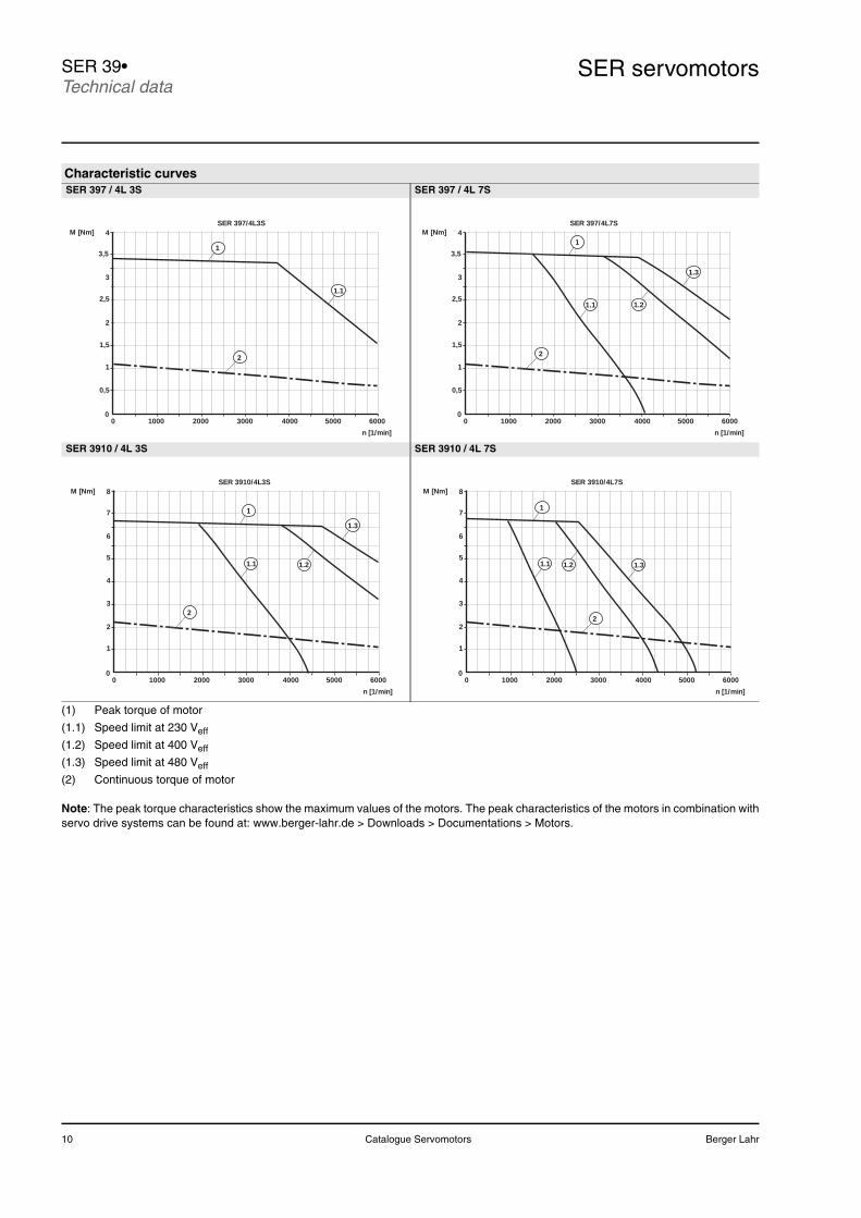
SER servomotorsSER 39•Technical data
(1) Peak torque of motor
(1.1) Speed limit at 230 Veff
(1.2) Speed limit at 400 Veff
(1.3) Speed limit at 480 Veff
(2) Continuous torque of motor
Note: The peak torque characteristics show the maximum values of the motors. The peak characteristics of the motors in combination withservo drive systems can be found at: www.berger-lahr.de > Downloads > Documentations > Motors.
Characteristic curvesSER 397 / 4L 3S SER 397 / 4L 7S
SER 3910 / 4L 3S SER 3910 / 4L 7S
1
1,5
2
0,5
SER 397/4L3S
010000 2000 3000 4000 5000 6000
n [1/min]
M [Nm] 4
2,5
1
3
3,5
2
1.1
1
1,5
2
0,5
SER 397/4L7S
010000 2000 3000 4000 5000 6000
n [1/min]
M [Nm] 4
2,5
1
3
3,5
2
1.1 1.2
1.3
1
3
SER 3910/4L3S
010000 2000 3000 4000 5000 6000
n [1/min]
M [Nm] 8
1
6
2
1.1 1.2
1.3
2
4
5
7
1
3
SER 3910/4L7S
010000 2000 3000 4000 5000 6000
n [1/min]
M [Nm] 8
1
6
2
1.1 1.2 1.3
2
4
5
7
Berger Lahr Catalogue Servomotors 11
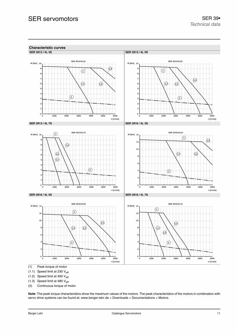
SER servomotors SER 39•Technical data
(1) Peak torque of motor
(1.1) Speed limit at 230 Veff
(1.2) Speed limit at 400 Veff
(1.3) Speed limit at 480 Veff
(2) Continuous torque of motor
Note: The peak torque characteristics show the maximum values of the motors. The peak characteristics of the motors in combination withservo drive systems can be found at: www.berger-lahr.de > Downloads > Documentations > Motors.
Characteristic curvesSER 3913 / 4L 3S SER 3913 / 4L 5S
SER 3913 / 4L 7S SER 3916 / 4L 3S
SER 3916 / 4L 5S SER 3916 / 4L 7S
8
5
3
2
1
SER 3913/4L3S
010000 2000 3000 4000 5000 6000
n [1/min]
M [Nm]
91
6
2
1.1 1.2
1.3
4
7
10
8
5
3
2
1
SER 3913/4L5S
010000 2000 3000 4000 5000 6000
n [1/min]
M [Nm]
91
6
2
1.1 1.2
1.3
4
7
10
8
5
3
2
1
SER 3913/4L7S
010000 2000 3000 4000 5000 6000
n [1/min]
M [Nm]
9
6
2
1.1
1.2
1.3
4
7
10 1
10
6
12
8
4
2
SER 3916/4L3S
010000 2000 3000 4000 5000 6000
n [1/min]
M [Nm]
2
1.1 1.2
1.3
14
1
10
6
12
8
4
2
SER 3916/4L5S
010000 2000 3000 4000 5000 6000
n [1/min]
M [Nm]
2
1.1 1.2
1.3
14
1
10
6
12
8
4
2
SER 3916/4L7S
010000 2000 3000 4000 5000 6000
n [1/min]
M [Nm]
2
1.1
1.2
1.3
14
1
12 Catalogue Servomotors Berger Lahr
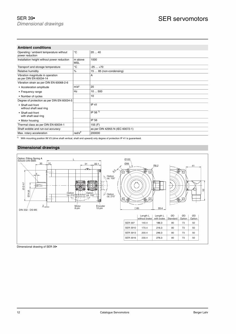
SER servomotorsSER 39•Dimensional drawings
Dimensional drawing of SER 39•
Ambient conditionsOperating / ambient temperature without power reduction
°C 20 ... 40
Installation height without power reduction m above MSL
1000
Transport and storage temperature °C -25 ... +70
Relative humidity % 15 … 85 (non-condensing)
Vibration magnitude in operation as per DIN EN 60034-14
A
Vibration strain as per DIN EN 60068-2-6
• Acceleration amplitude m/s² 20
• Frequency range Hz 10 ... 500
• Number of cycles 10
Degree of protection as per DIN EN 60034-5
• Shaft exit frontwithout shaft seal ring
IP 41
• Shaft exit frontwith shaft seal ring
IP 56 1)
• Motor housing IP 56
Thermal class as per DIN EN 60034-1 155 (F)
Shaft wobble and run-out accuracy as per DIN 42955 N (IEC 60072-1)
Max. rotary acceleration rad/s2 200000
1) With mounting position IM V3 (drive shaft vertical, shaft end upward) only degree of protection IP 41 is guaranteed.
Dimensional drawings
Ø14
j6
Ø D
h7
5
31
L
12
285
Ø100
Ø99
33.4
41
52
DIN 332 - DS-M5
30
SER 3913
SER 3910
SER 397
SER 3916
80
80
80
80
73
73
73
73
50
50
50
50
Option: Fitting Spring A5x5x20 DIN 6885
22.1
ca. 210˚Option
ca. 100˚Option
Motor8-pin
Encoder12-pin
ca. 210˚Option
Option ca. 100˚
6.5
Length Lwithout brake
Length Lwith brake
ØDStandard
ØDOption
ØDOption
200.4
230.4
170.4
140.4
246.3
276.3
216.3
186.3
R8.2
Berger Lahr Catalogue Servomotors 13
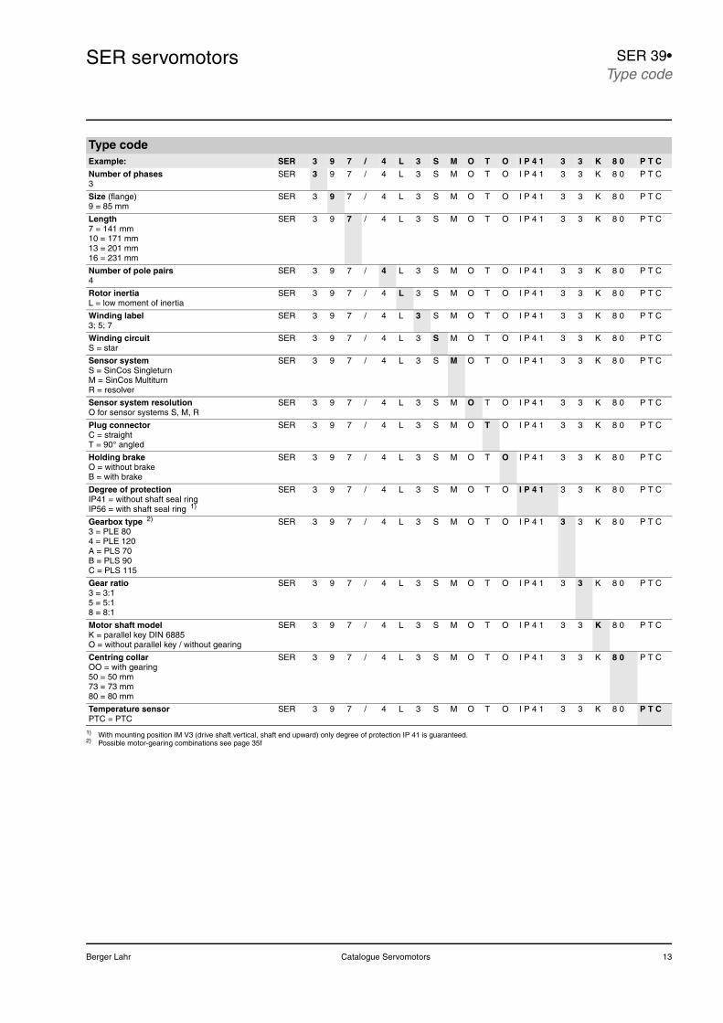
SER servomotors SER 39•Type code
Type codeExample: SER 3 9 7 / 4 L 3 S M O T O I P 4 1 3 3 K 8 0 P T C
Number of phases3
SER 3 9 7 / 4 L 3 S M O T O I P 4 1 3 3 K 8 0 P T C
Size (flange) 9 = 85 mm
SER 3 9 7 / 4 L 3 S M O T O I P 4 1 3 3 K 8 0 P T C
Length7 = 141 mm10 = 171 mm13 = 201 mm16 = 231 mm
SER 3 9 7 / 4 L 3 S M O T O I P 4 1 3 3 K 8 0 P T C
Number of pole pairs4
SER 3 9 7 / 4 L 3 S M O T O I P 4 1 3 3 K 8 0 P T C
Rotor inertiaL = low moment of inertia
SER 3 9 7 / 4 L 3 S M O T O I P 4 1 3 3 K 8 0 P T C
Winding label3; 5; 7
SER 3 9 7 / 4 L 3 S M O T O I P 4 1 3 3 K 8 0 P T C
Winding circuitS = star
SER 3 9 7 / 4 L 3 S M O T O I P 4 1 3 3 K 8 0 P T C
Sensor systemS = SinCos SingleturnM = SinCos MultiturnR = resolver
SER 3 9 7 / 4 L 3 S M O T O I P 4 1 3 3 K 8 0 P T C
Sensor system resolutionO for sensor systems S, M, R
SER 3 9 7 / 4 L 3 S M O T O I P 4 1 3 3 K 8 0 P T C
Plug connectorC = straightT = 90° angled
SER 3 9 7 / 4 L 3 S M O T O I P 4 1 3 3 K 8 0 P T C
Holding brakeO = without brakeB = with brake
SER 3 9 7 / 4 L 3 S M O T O I P 4 1 3 3 K 8 0 P T C
Degree of protectionIP41 = without shaft seal ringIP56 = with shaft seal ring 1)
SER 3 9 7 / 4 L 3 S M O T O I P 4 1 3 3 K 8 0 P T C
Gearbox type 2)
3 = PLE 804 = PLE 120A = PLS 70B = PLS 90C = PLS 115
SER 3 9 7 / 4 L 3 S M O T O I P 4 1 3 3 K 8 0 P T C
Gear ratio3 = 3:15 = 5:18 = 8:1
SER 3 9 7 / 4 L 3 S M O T O I P 4 1 3 3 K 8 0 P T C
Motor shaft modelK = parallel key DIN 6885O = without parallel key / without gearing
SER 3 9 7 / 4 L 3 S M O T O I P 4 1 3 3 K 8 0 P T C
Centring collarOO = with gearing50 = 50 mm73 = 73 mm80 = 80 mm
SER 3 9 7 / 4 L 3 S M O T O I P 4 1 3 3 K 8 0 P T C
Temperature sensorPTC = PTC
SER 3 9 7 / 4 L 3 S M O T O I P 4 1 3 3 K 8 0 P T C
1) With mounting position IM V3 (drive shaft vertical, shaft end upward) only degree of protection IP 41 is guaranteed.2) Possible motor-gearing combinations see page 35f
14 Catalogue Servomotors Berger Lahr
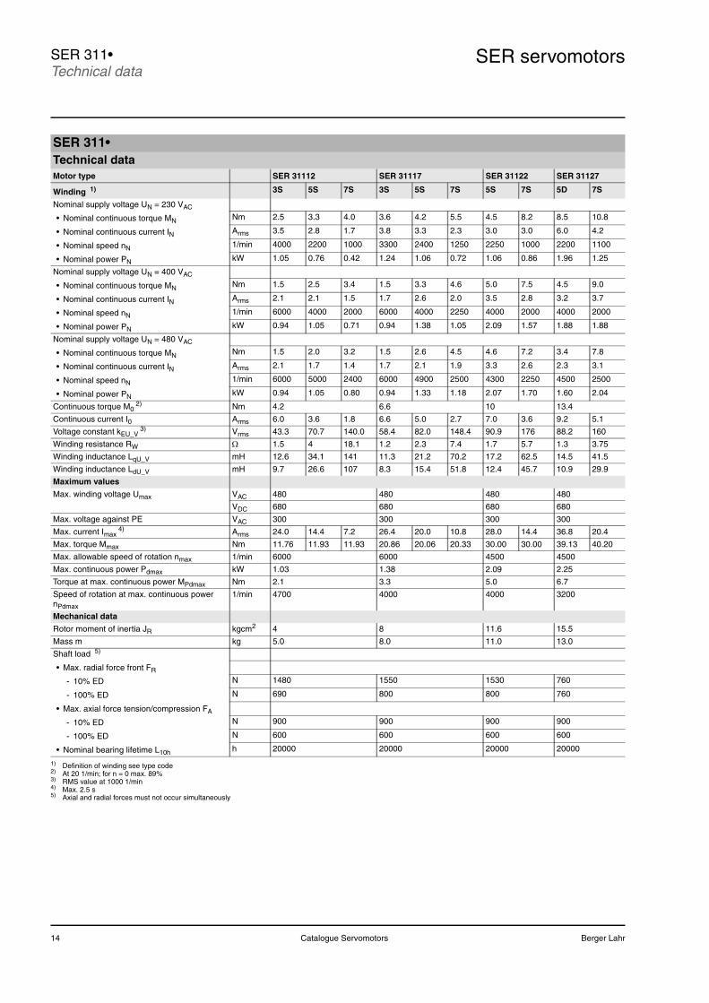
SER servomotorsSER 311•Technical data
SER 311•Technical dataMotor type SER 31112 SER 31117 SER 31122 SER 31127
Winding 1) 3S 5S 7S 3S 5S 7S 5S 7S 5D 7S
Nominal supply voltage UN = 230 VAC
• Nominal continuous torque MN Nm 2.5 3.3 4.0 3.6 4.2 5.5 4.5 8.2 8.5 10.8
• Nominal continuous current IN Arms 3.5 2.8 1.7 3.8 3.3 2.3 3.0 3.0 6.0 4.2
• Nominal speed nN 1/min 4000 2200 1000 3300 2400 1250 2250 1000 2200 1100
• Nominal power PN kW 1.05 0.76 0.42 1.24 1.06 0.72 1.06 0.86 1.96 1.25
Nominal supply voltage UN = 400 VAC
• Nominal continuous torque MN Nm 1.5 2.5 3.4 1.5 3.3 4.6 5.0 7.5 4.5 9.0
• Nominal continuous current IN Arms 2.1 2.1 1.5 1.7 2.6 2.0 3.5 2.8 3.2 3.7
• Nominal speed nN 1/min 6000 4000 2000 6000 4000 2250 4000 2000 4000 2000
• Nominal power PN kW 0.94 1.05 0.71 0.94 1.38 1.05 2.09 1.57 1.88 1.88
Nominal supply voltage UN = 480 VAC
• Nominal continuous torque MN Nm 1.5 2.0 3.2 1.5 2.6 4.5 4.6 7.2 3.4 7.8
• Nominal continuous current IN Arms 2.1 1.7 1.4 1.7 2.1 1.9 3.3 2.6 2.3 3.1
• Nominal speed nN 1/min 6000 5000 2400 6000 4900 2500 4300 2250 4500 2500
• Nominal power PN kW 0.94 1.05 0.80 0.94 1.33 1.18 2.07 1.70 1.60 2.04
Continuous torque M02) Nm 4.2 6.6 10 13.4
Continuous current I0 Arms 6.0 3.6 1.8 6.6 5.0 2.7 7.0 3.6 9.2 5.1
Voltage constant kEU_V3) Vrms 43.3 70.7 140.0 58.4 82.0 148.4 90.9 176 88.2 160
Winding resistance RW Ω 1.5 4 18.1 1.2 2.3 7.4 1.7 5.7 1.3 3.75
Winding inductance LqU_V mH 12.6 34.1 141 11.3 21.2 70.2 17.2 62.5 14.5 41.5
Winding inductance LdU_V mH 9.7 26.6 107 8.3 15.4 51.8 12.4 45.7 10.9 29.9
Maximum values
Max. winding voltage Umax VAC 480 480 480 480
VDC 680 680 680 680
Max. voltage against PE VAC 300 300 300 300
Max. current Imax4) Arms 24.0 14.4 7.2 26.4 20.0 10.8 28.0 14.4 36.8 20.4
Max. torque Mmax Nm 11.76 11.93 11.93 20.86 20.06 20.33 30.00 30.00 39.13 40.20
Max. allowable speed of rotation nmax 1/min 6000 6000 4500 4500
Max. continuous power Pdmax kW 1.03 1.38 2.09 2.25
Torque at max. continuous power MPdmax Nm 2.1 3.3 5.0 6.7
Speed of rotation at max. continuous power nPdmax
1/min 4700 4000 4000 3200
Mechanical data
Rotor moment of inertia JR kgcm2 4 8 11.6 15.5
Mass m kg 5.0 8.0 11.0 13.0
Shaft load 5)
• Max. radial force front FR
- 10% ED N 1480 1550 1530 760
- 100% ED N 690 800 800 760
• Max. axial force tension/compression FA
- 10% ED N 900 900 900 900
- 100% ED N 600 600 600 600
• Nominal bearing lifetime L10h h 20000 20000 20000 20000
1) Definition of winding see type code2) At 20 1/min; for n = 0 max. 89%3) RMS value at 1000 1/min4) Max. 2.5 s 5) Axial and radial forces must not occur simultaneously
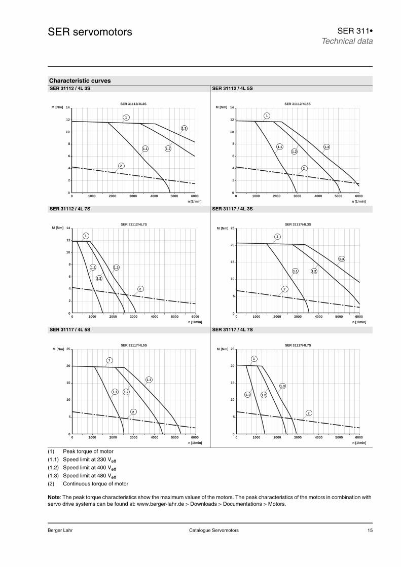
Berger Lahr Catalogue Servomotors 15
SER servomotors SER 311•Technical data
(1) Peak torque of motor
(1.1) Speed limit at 230 Veff
(1.2) Speed limit at 400 Veff
(1.3) Speed limit at 480 Veff
(2) Continuous torque of motor
Note: The peak torque characteristics show the maximum values of the motors. The peak characteristics of the motors in combination with servo drive systems can be found at: www.berger-lahr.de > Downloads > Documentations > Motors.
Characteristic curvesSER 31112 / 4L 3S SER 31112 / 4L 5S
SER 31112 / 4L 7S SER 31117 / 4L 3S
SER 31117 / 4L 5S SER 31117 / 4L 7S
10
6
12
8
4
2
SER 31112/4L3S
010000 2000 3000 4000 5000 6000
n [1/min]
M [Nm]
2
1.1 1.2
1.3
14
1
10
6
12
8
4
2
SER 31112/4L5S
010000 2000 3000 4000 5000 6000
n [1/min]
M [Nm]
2
1.11.2
1.3
14
1
10
6
12
8
4
2
SER 31112/4L7S
010000 2000 3000 4000 5000 6000
n [1/min]
M [Nm]
2
1.1
1.2
1.3
14
1
10
SER 31117/4L3S
010000 2000 3000 4000 5000 6000
n [1/min]
M [Nm]
1.1
2
1
5
15
20
25
1.2
1.3
10
SER 31117/4L5S
010000 2000 3000 4000 5000 6000
n [1/min]
M [Nm]
1.1
2
1
5
15
20
25
1.2
1.3
10
SER 31117/4L7S
010000 2000 3000 4000 5000 6000
n [1/min]
M [Nm]
2
1
5
15
20
25
1.3
1.1 1.2
16 Catalogue Servomotors Berger Lahr
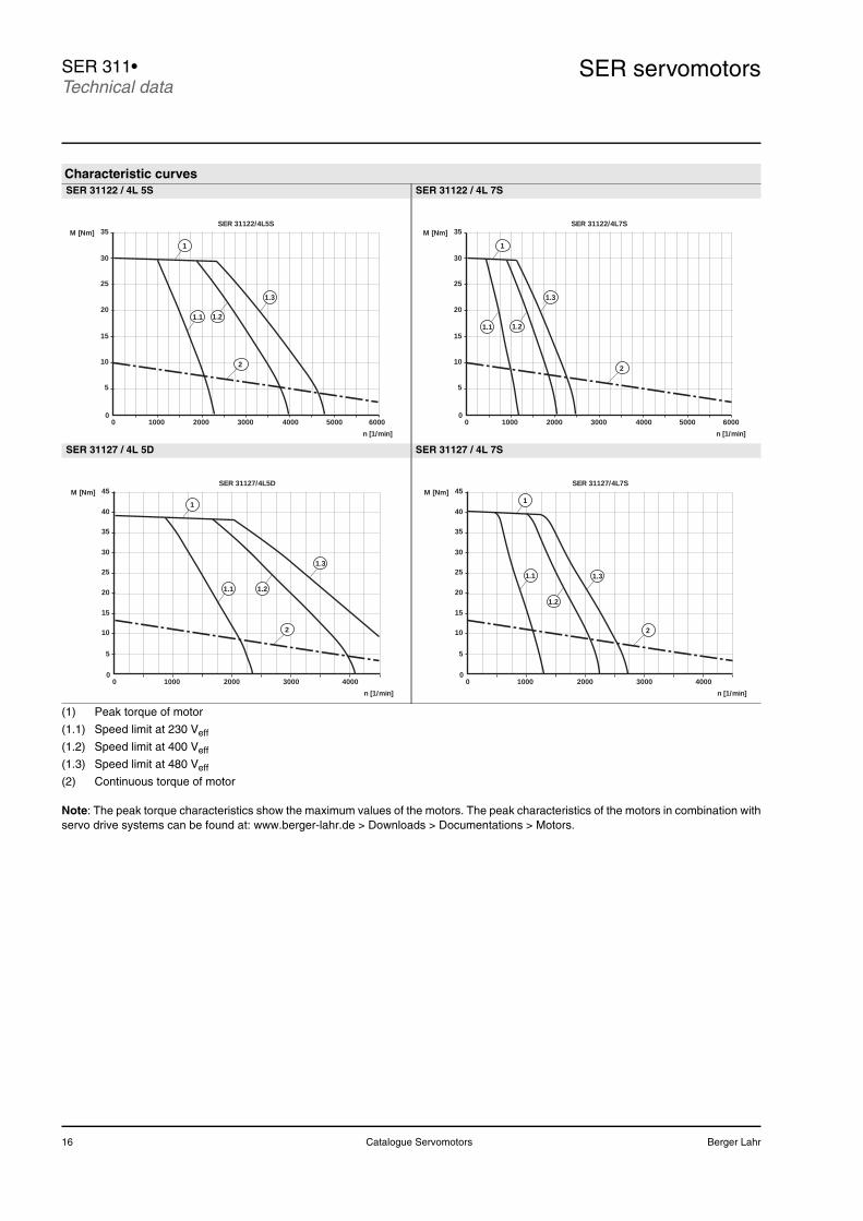
SER servomotorsSER 311•Technical data
(1) Peak torque of motor
(1.1) Speed limit at 230 Veff
(1.2) Speed limit at 400 Veff
(1.3) Speed limit at 480 Veff
(2) Continuous torque of motor
Note: The peak torque characteristics show the maximum values of the motors. The peak characteristics of the motors in combination withservo drive systems can be found at: www.berger-lahr.de > Downloads > Documentations > Motors.
Characteristic curvesSER 31122 / 4L 5S SER 31122 / 4L 7S
SER 31127 / 4L 5D SER 31127 / 4L 7S
30
5
10
SER 31122/4L5S
010000 2000 3000 4000 5000 6000
n [1/min]
M [Nm]
1
15
20
25
35
2
1.1
1.3
1.2
30
5
10
SER 31122/4L7S
010000 2000 3000 4000 5000 6000
n [1/min]
M [Nm]
1
15
20
25
35
2
1.1
1.3
1.2
20
15
10
5
SER 31127/4L5D
010000 2000
n [1/min]
M [Nm]
1
2
25
30
35
40
45
3000 4000
1.2
1.3
1.1 20
15
10
5
SER 31127/4L7S
010000 2000
n [1/min]
M [Nm]1
2
25
30
35
40
45
3000 4000
1.2
1.31.1
Berger Lahr Catalogue Servomotors 17
SER servomotors SER 311•Dimensional drawings
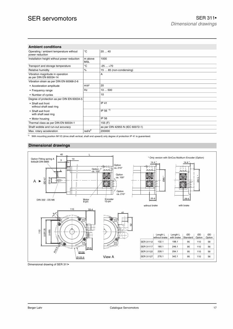
Dimensional drawing of SER 311•
Ambient conditionsOperating / ambient temperature without power reduction
°C 20 ... 40
Installation height without power reduction m above MSL
1000
Transport and storage temperature °C -25 ... +70
Relative humidity % 15 … 85 (non-condensing)
Vibration magnitude in operation as per DIN EN 60034-14
A
Vibration strain as per DIN EN 60068-2-6
• Acceleration amplitude m/s² 20
• Frequency range Hz 10 ... 500
• Number of cycles 10
Degree of protection as per DIN EN 60034-5
• Shaft exit frontwithout shaft seal ring
IP 41
• Shaft exit frontwith shaft seal ring
IP 56 1)
• Motor housing IP 56
Thermal class as per DIN EN 60034-1 155 (F)
Shaft wobble and run-out accuracy as per DIN 42955 N (IEC 60072-1)
Max. rotary acceleration rad/s2 200000
1) With mounting position IM V3 (drive shaft vertical, shaft end upward) only degree of protection IP 41 is guaranteed.
Dimensional drawings
SER 31122
SER 31117
SER 31112
SER 31127
95
95
95
95
110
110
110
110
56
56
56
56
with brake
14.4 *
Ø8
5 *
28.6
without brake
L
Ø19
j6
ØD
h7
40
14314.4 *
Ø85
*
5
DIN 332 - DS M612-pinEncoder
8-pinMotor
Option Fitting spring A6x6x28 DIN 6885
Option ca. 100°
Optionca. 210°
Length Lwithout brake
Length Lwith brake
ØDStandard
ØDOption
ØDOption
228.1
276.1
180.1
132.1
294.1
342.1
246.1
198.1
( 9
1.9)
( 8
9)
Ø125.9
110
Ø130R10
.5
9
11041
33.4
23.6
52
* Only version with SinCos Multiturn Encoder (Option)
Optionca. 100°
Optionca. 210°
25.6
A
View A
18 Catalogue Servomotors Berger Lahr
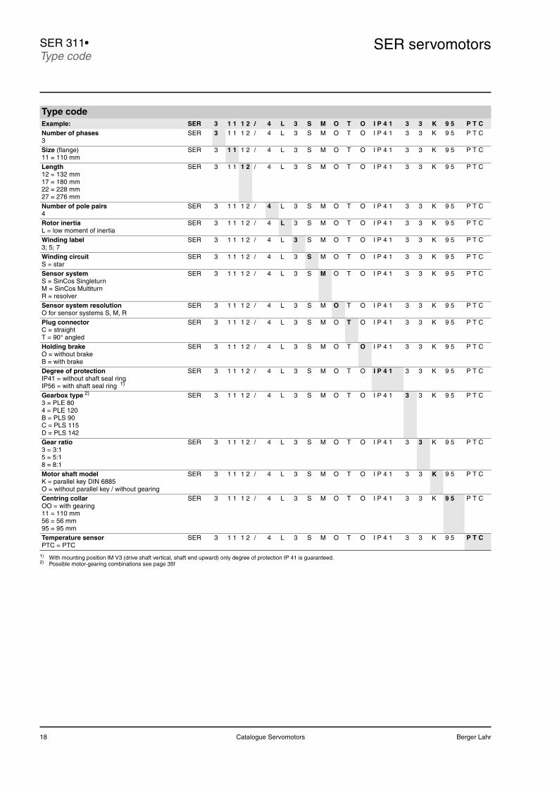
SER servomotorsSER 311•Type code
Type codeExample: SER 3 1 1 1 2 / 4 L 3 S M O T O I P 4 1 3 3 K 9 5 P T CNumber of phases3
SER 3 1 1 1 2 / 4 L 3 S M O T O I P 4 1 3 3 K 9 5 P T C
Size (flange) 11 = 110 mm
SER 3 1 1 1 2 / 4 L 3 S M O T O I P 4 1 3 3 K 9 5 P T C
Length12 = 132 mm17 = 180 mm22 = 228 mm27 = 276 mm
SER 3 1 1 1 2 / 4 L 3 S M O T O I P 4 1 3 3 K 9 5 P T C
Number of pole pairs4
SER 3 1 1 1 2 / 4 L 3 S M O T O I P 4 1 3 3 K 9 5 P T C
Rotor inertiaL = low moment of inertia
SER 3 1 1 1 2 / 4 L 3 S M O T O I P 4 1 3 3 K 9 5 P T C
Winding label3; 5; 7
SER 3 1 1 1 2 / 4 L 3 S M O T O I P 4 1 3 3 K 9 5 P T C
Winding circuitS = star
SER 3 1 1 1 2 / 4 L 3 S M O T O I P 4 1 3 3 K 9 5 P T C
Sensor systemS = SinCos SingleturnM = SinCos MultiturnR = resolver
SER 3 1 1 1 2 / 4 L 3 S M O T O I P 4 1 3 3 K 9 5 P T C
Sensor system resolutionO for sensor systems S, M, R
SER 3 1 1 1 2 / 4 L 3 S M O T O I P 4 1 3 3 K 9 5 P T C
Plug connectorC = straightT = 90° angled
SER 3 1 1 1 2 / 4 L 3 S M O T O I P 4 1 3 3 K 9 5 P T C
Holding brakeO = without brakeB = with brake
SER 3 1 1 1 2 / 4 L 3 S M O T O I P 4 1 3 3 K 9 5 P T C
Degree of protectionIP41 = without shaft seal ringIP56 = with shaft seal ring 1)
SER 3 1 1 1 2 / 4 L 3 S M O T O I P 4 1 3 3 K 9 5 P T C
Gearbox type 2)
3 = PLE 804 = PLE 120B = PLS 90C = PLS 115D = PLS 142
SER 3 1 1 1 2 / 4 L 3 S M O T O I P 4 1 3 3 K 9 5 P T C
Gear ratio3 = 3:15 = 5:18 = 8:1
SER 3 1 1 1 2 / 4 L 3 S M O T O I P 4 1 3 3 K 9 5 P T C
Motor shaft modelK = parallel key DIN 6885O = without parallel key / without gearing
SER 3 1 1 1 2 / 4 L 3 S M O T O I P 4 1 3 3 K 9 5 P T C
Centring collarOO = with gearing11 = 110 mm56 = 56 mm95 = 95 mm
SER 3 1 1 1 2 / 4 L 3 S M O T O I P 4 1 3 3 K 9 5 P T C
Temperature sensorPTC = PTC
SER 3 1 1 1 2 / 4 L 3 S M O T O I P 4 1 3 3 K 9 5 P T C
1) With mounting position IM V3 (drive shaft vertical, shaft end upward) only degree of protection IP 41 is guaranteed.2) Possible motor-gearing combinations see page 35f
Berger Lahr Catalogue Servomotors 19
SER servomotors SER 311•
20 Catalogue Servomotors Berger Lahr
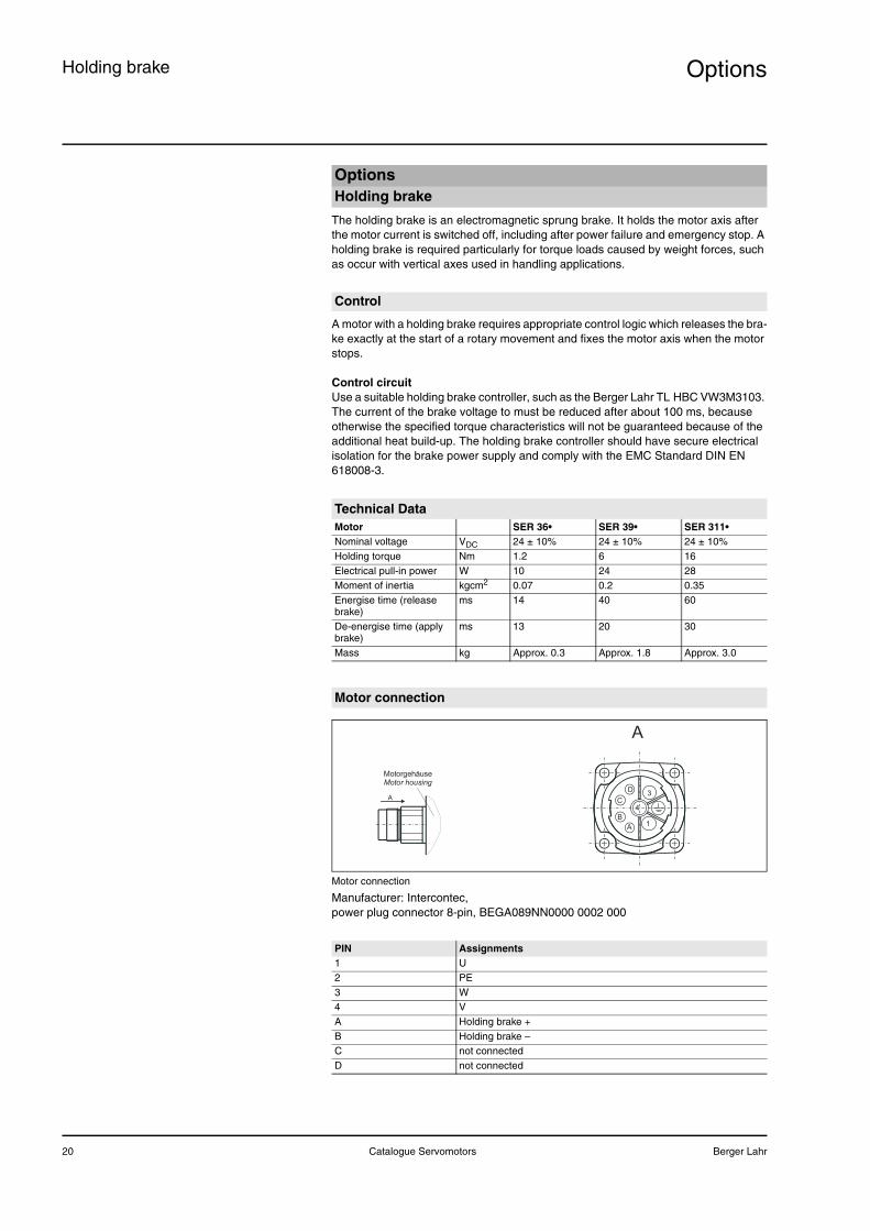
OptionsHolding brake
The holding brake is an electromagnetic sprung brake. It holds the motor axis after the motor current is switched off, including after power failure and emergency stop. A holding brake is required particularly for torque loads caused by weight forces, such as occur with vertical axes used in handling applications.
A motor with a holding brake requires appropriate control logic which releases the bra-ke exactly at the start of a rotary movement and fixes the motor axis when the motor stops.
Control circuitUse a suitable holding brake controller, such as the Berger Lahr TL HBC VW3M3103. The current of the brake voltage to must be reduced after about 100 ms, because otherwise the specified torque characteristics will not be guaranteed because of the additional heat build-up. The holding brake controller should have secure electrical isolation for the brake power supply and comply with the EMC Standard DIN EN 618008-3.
Motor connection
Manufacturer: Intercontec, power plug connector 8-pin, BEGA089NN0000 0002 000
OptionsHolding brake
Control
Technical DataMotor SER 36• SER 39• SER 311•Nominal voltage VDC 24 ± 10% 24 ± 10% 24 ± 10%Holding torque Nm 1.2 6 16Electrical pull-in power W 10 24 28Moment of inertia kgcm2 0.07 0.2 0.35Energise time (release brake)
ms 14 40 60
De-energise time (apply brake)
ms 13 20 30
Mass kg Approx. 0.3 Approx. 1.8 Approx. 3.0
Motor connection
PIN Assignments1 U2 PE3 W4 VA Holding brake +B Holding brake –C not connectedD not connected
A
B
C
D
1
4
3
A
A
MotorgehäuseMotor housing
Berger Lahr Catalogue Servomotors 21
Options Position capture
SinCos (SRS50) SingleturnThe "SinCos (SRS50) Singleturn" sensor system measures an absolute value within one revolution after being switched on and continues to count incrementally from this point.
For more information see www.stegmann.de
SinCos (SRSM50) MultiturnThe "SinCos (SRM50) Multiturn" sensor system measures an absolute value within 4096 revolutions after being switched on and continues to count incrementally from this point.
For more information see www.stegmann.de
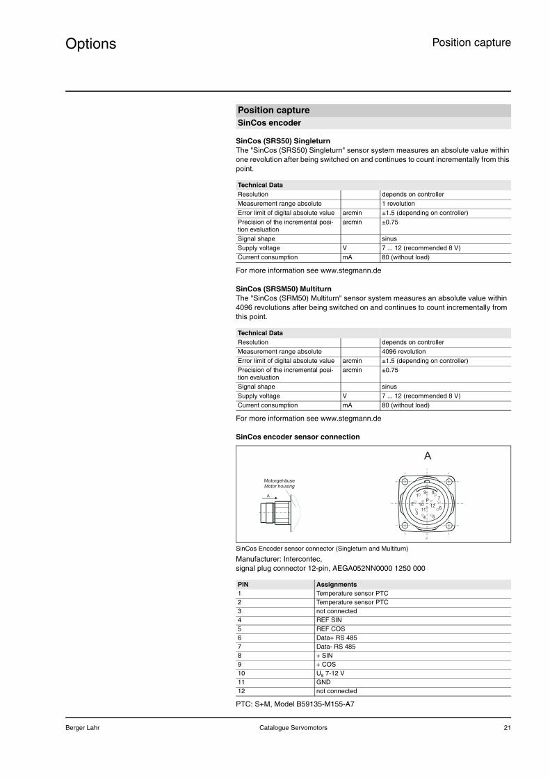
SinCos encoder sensor connection
SinCos Encoder sensor connector (Singleturn and Multiturn)
Manufacturer: Intercontec, signal plug connector 12-pin, AEGA052NN0000 1250 000
PTC: S+M, Model B59135-M155-A7
Position captureSinCos encoder
Technical DataResolution depends on controllerMeasurement range absolute 1 revolutionError limit of digital absolute value arcmin ±1.5 (depending on controller)Precision of the incremental posi-tion evaluation
arcmin ±0.75
Signal shape sinusSupply voltage V 7 ... 12 (recommended 8 V)Current consumption mA 80 (without load)
Technical DataResolution depends on controllerMeasurement range absolute 4096 revolutionError limit of digital absolute value arcmin ±1.5 (depending on controller)Precision of the incremental posi-tion evaluation
arcmin ±0.75
Signal shape sinusSupply voltage V 7 ... 12 (recommended 8 V)Current consumption mA 80 (without load)
PIN Assignments1 Temperature sensor PTC2 Temperature sensor PTC3 not connected4 REF SIN5 REF COS6 Data+ RS 4857 Data- RS 4858 + SIN9 + COS10 Us 7-12 V11 GND12 not connected
A
MotorgehäuseMotor housing
11
9
6
5
7
12
8
34
10
1
2P
A
22 Catalogue Servomotors Berger Lahr
OptionsPosition capture
The "resolver" sensor system is a very robust system. Absolute position capture is possible within one revolution.
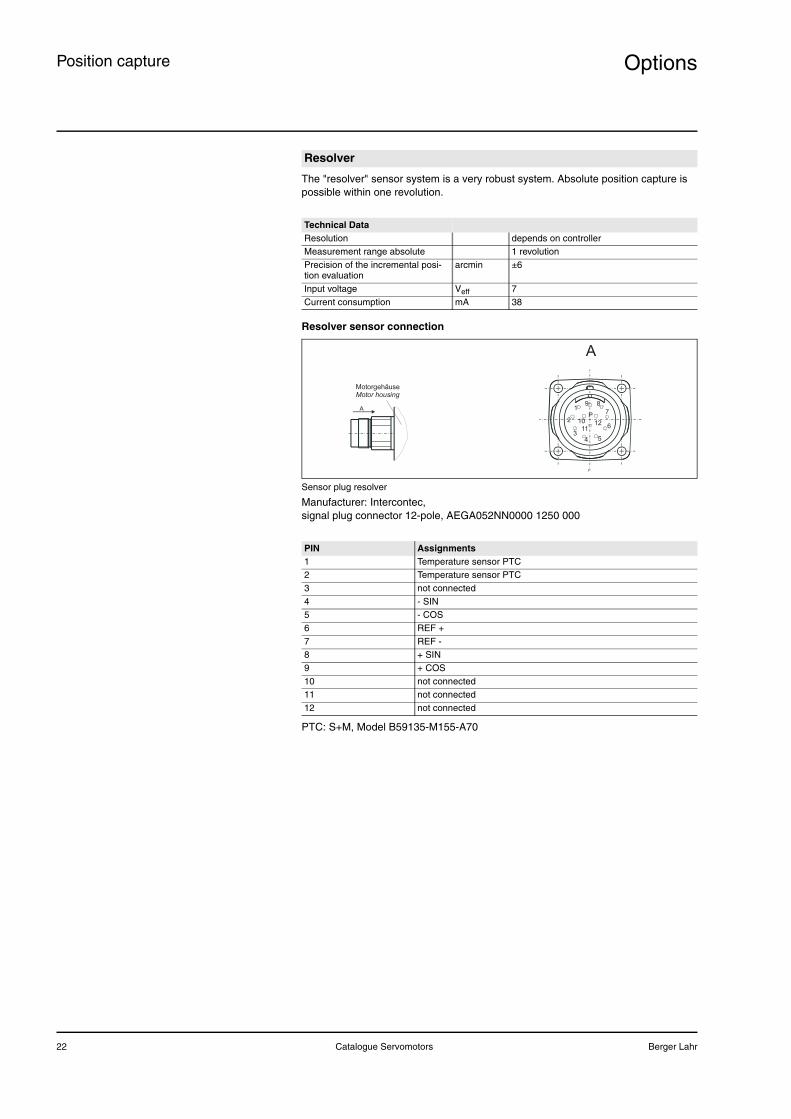
Resolver sensor connection
Sensor plug resolver
Manufacturer: Intercontec, signal plug connector 12-pole, AEGA052NN0000 1250 000
PTC: S+M, Model B59135-M155-A70
Resolver
Technical DataResolution depends on controllerMeasurement range absolute 1 revolutionPrecision of the incremental posi-tion evaluation
arcmin ±6
Input voltage Veff 7Current consumption mA 38
PIN Assignments1 Temperature sensor PTC2 Temperature sensor PTC3 not connected4 - SIN 5 - COS6 REF +7 REF -8 + SIN9 + COS10 not connected11 not connected12 not connected
A
MotorgehäuseMotor housing
11
9
6
5
7
12
8
34
10
1
2P
A
Berger Lahr Catalogue Servomotors 23
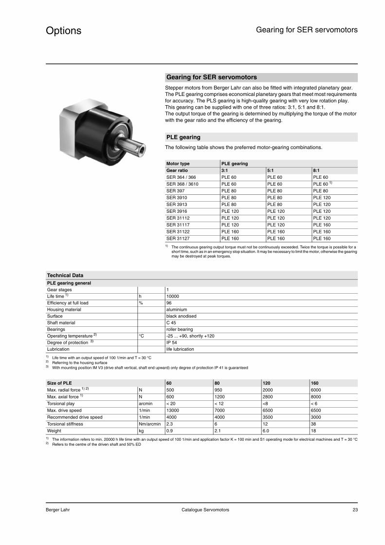
Options Gearing for SER servomotors
Stepper motors from Berger Lahr can also be fitted with integrated planetary gear. The PLE gearing comprises economical planetary gears that meet most requirements for accuracy. The PLS gearing is high-quality gearing with very low rotation play.This gearing can be supplied with one of three ratios: 3:1, 5:1 and 8:1.The output torque of the gearing is determined by multiplying the torque of the motor with the gear ratio and the efficiency of the gearing.
The following table shows the preferred motor-gearing combinations.
Gearing for SER servomotors
PLE gearing
Motor type PLE gearing
Gear ratio 3:1 5:1 8:1
SER 364 / 366 PLE 60 PLE 60 PLE 60
SER 368 / 3610 PLE 60 PLE 60 PLE 60 1)
1) The continuous gearing output torque must not be continuously exceeded. Twice the torque is possible for a short time, such as in an emergency stop situation. It may be necessary to limit the motor, otherwise the gearing may be destroyed at peak torques.
SER 397 PLE 80 PLE 80 PLE 80
SER 3910 PLE 80 PLE 80 PLE 120
SER 3913 PLE 80 PLE 80 PLE 120
SER 3916 PLE 120 PLE 120 PLE 120
SER 31112 PLE 120 PLE 120 PLE 120
SER 31117 PLE 120 PLE 120 PLE 160
SER 31122 PLE 160 PLE 160 PLE 160
SER 31127 PLE 160 PLE 160 PLE 160
Technical DataPLE gearing generalGear stages 1
Life time 1) h 10000
Efficiency at full load % 96
Housing material aluminium
Surface black anodised
Shaft material C 45
Bearings roller bearing
Operating temperature 2) °C -25 ... +90, shortly +120
Degree of protection 3) IP 54
Lubrication life lubrication
1) Life time with an output speed of 100 1/min and T = 30 °C2) Referring to the housing surface3) With mounting position IM V3 (drive shaft vertical, shaft end upward) only degree of protection IP 41 is guaranteed
Size of PLE 60 80 120 160
Max. radial force 1) 2) N 500 950 2000 6000
Max. axial force 1) N 600 1200 2800 8000
Torsional play arcmin < 20 < 12 <8 < 6
Max. drive speed 1/min 13000 7000 6500 6500
Recommended drive speed 1/min 4000 4000 3500 3000
Torsional stiffness Nm/arcmin 2.3 6 12 38
Weight kg 0.9 2.1 6.0 18
1) The information refers to min. 20000 h life time with an output speed of 100 1/min and application factor K = 100 min and S1 operating mode for electrical machines and T = 30 °C2) Refers to the centre of the driven shaft and 50% ED
24 Catalogue Servomotors Berger Lahr
OptionsGearing for SER servomotors
The following table shows the recommended motor-gearing combinations.
PLS gearing
Motor type PLS gearingGear ratio 3:1 5:1 8:1SER 36• PLS 70 PLS 70 PLS 70SER 397 PLS 70 PLS 70 PLS 70SER 3910 PLS 70 PLS 70 PLS 90SER 3913 PLS 70 PLS 90 PLS 115SER 3916 PLS 90 PLS 90 PLS 115SER 31112 PLS 90 PLS 90 PLS 115SER 31117 PLS 90 PLS 115 PLS 142SER 31122 PLS 115 PLS 115 PLS 142SER 31127 PLS 115 PLS 142 PLS 142
Technical DataPLS gearing general
Gear stages 1
Life time 1) h 20000
Efficiency at full load % 98
Housing material aluminium
Surface black anodised
Shaft material C 45
Bearings tapered roller bearings
Operating temperature 2) °C -25 ... +100, shortly +124
Degree of protection 3) IP 65
Lubrication life lubrication
1) Life time with an output speed of 100 1/min and T = 30 °C2) Referring to the housing surface3) With mounting position IM V3 (drive shaft vertical, shaft end upward) only protection class IP 41 is guaranteed
Size of PLS 70 90 115 142
Max. radial force 1) 2) N 3000 4000 5000 9000
Max. axial force 1) N 6000 9000 12000 15000
Torsional play arcmin <3 <3 <3 <3
Max. drive speed 1/min 14000 10000 8500 6500
Recommended drive speed 1/min 5000 4500 4000 3000
Torsional stiffness Nm/arcmin 6 9 20 44
Weight kg 3.0 4.3 9.0 15.4
1) The information refers to min. 20000 h life time with an output speed of 100 1/min and application factor K = 100 min and S1 operating mode for electrical machines and T = 30 °C2) Refers to the centre of the driven shaft and 50% ED
Berger Lahr Catalogue Servomotors 25
Options Gearing for SER servomotors
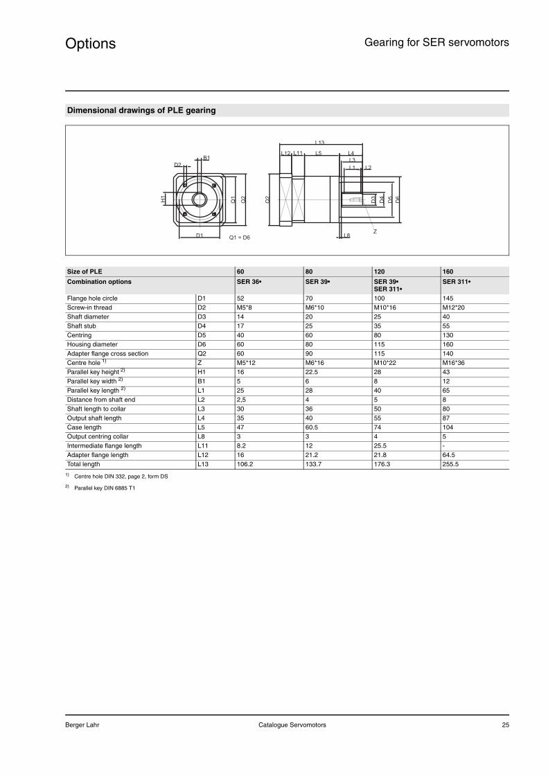
Dimensional drawings of PLE gearing
D3
D4
D5
D6
L1 L2
L3
L4L5L11L12
L13
L8
Q2
D1
D2H
1B1
Q1
Q2
Q1 = D6Z
Size of PLE 60 80 120 160
Combination options SER 36• SER 39• SER 39• SER 311•
SER 311•
Flange hole circle D1 52 70 100 145Screw-in thread D2 M5*8 M6*10 M10*16 M12*20Shaft diameter D3 14 20 25 40Shaft stub D4 17 25 35 55Centring D5 40 60 80 130Housing diameter D6 60 80 115 160Adapter flange cross section Q2 60 90 115 140Centre hole 1) Z M5*12 M6*16 M10*22 M16*36Parallel key height 2) H1 16 22.5 28 43Parallel key width 2) B1 5 6 8 12Parallel key length 2) L1 25 28 40 65Distance from shaft end L2 2,5 4 5 8Shaft length to collar L3 30 36 50 80Output shaft length L4 35 40 55 87Case length L5 47 60.5 74 104Output centring collar L8 3 3 4 5Intermediate flange length L11 8.2 12 25.5 -Adapter flange length L12 16 21.2 21.8 64.5Total length L13 106.2 133.7 176.3 255.5
1) Centre hole DIN 332, page 2, form DS
2) Parallel key DIN 6885 T1
26 Catalogue Servomotors Berger Lahr
OptionsGearing for SER servomotors
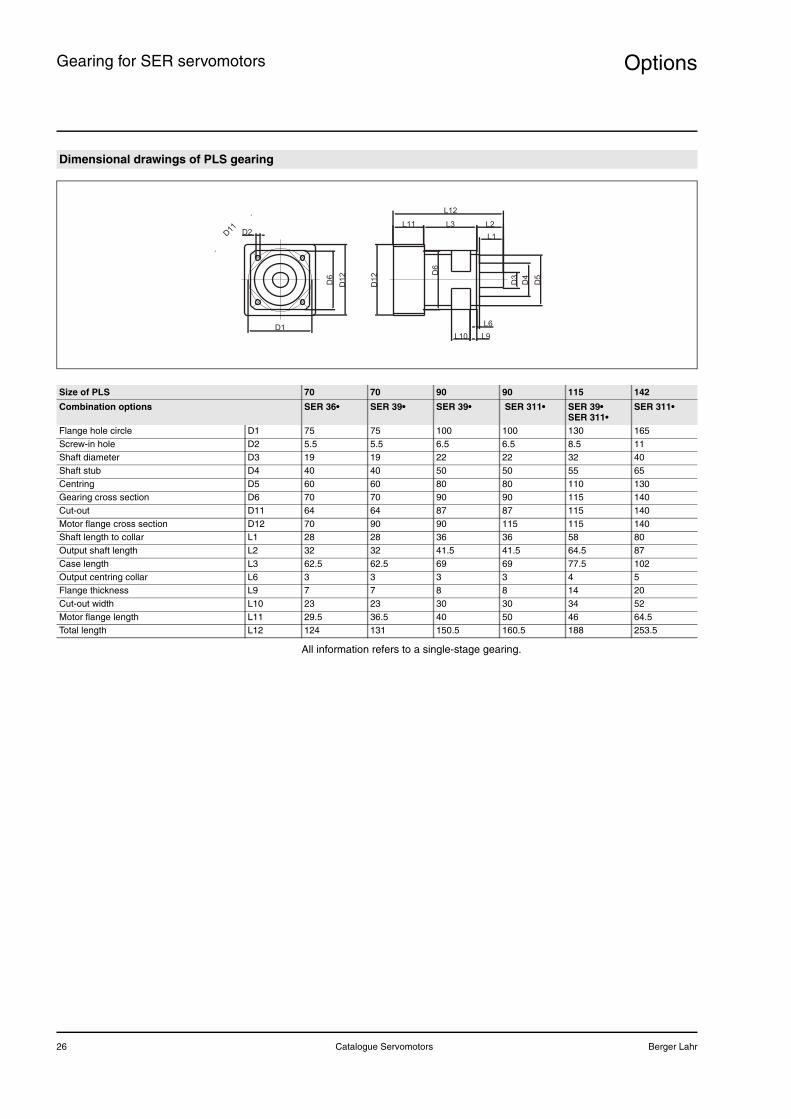
All information refers to a single-stage gearing.
Dimensional drawings of PLS gearing
D1
D2
D3
D4
D5
L1
L2
L6
L9L10
L3
L12
L11
D1
2 D6
D6
D1
2
D11
Size of PLS 70 70 90 90 115 142
Combination options SER 36• SER 39• SER 39• SER 311• SER 39• SER 311•
SER 311•
Flange hole circle D1 75 75 100 100 130 165Screw-in hole D2 5.5 5.5 6.5 6.5 8.5 11Shaft diameter D3 19 19 22 22 32 40Shaft stub D4 40 40 50 50 55 65Centring D5 60 60 80 80 110 130Gearing cross section D6 70 70 90 90 115 140Cut-out D11 64 64 87 87 115 140Motor flange cross section D12 70 90 90 115 115 140Shaft length to collar L1 28 28 36 36 58 80Output shaft length L2 32 32 41.5 41.5 64.5 87Case length L3 62.5 62.5 69 69 77.5 102Output centring collar L6 3 3 3 3 4 5Flange thickness L9 7 7 8 8 14 20Cut-out width L10 23 23 30 30 34 52Motor flange length L11 29.5 36.5 40 50 46 64.5Total length L12 124 131 150.5 160.5 188 253.5
Berger Lahr Catalogue Servomotors 27
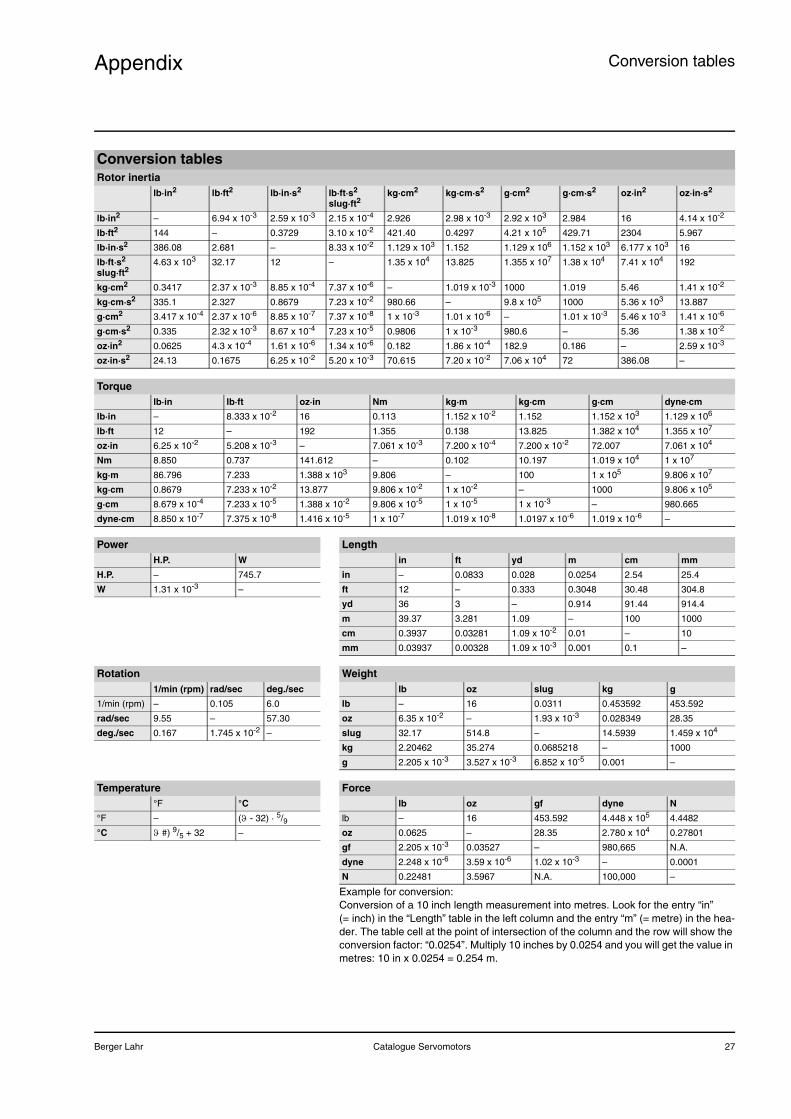
Appendix Conversion tables
Example for conversion:Conversion of a 10 inch length measurement into metres. Look for the entry “in” (= inch) in the “Length” table in the left column and the entry “m” (= metre) in the hea-der. The table cell at the point of intersection of the column and the row will show the conversion factor: “0.0254”. Multiply 10 inches by 0.0254 and you will get the value in metres: 10 in x 0.0254 = 0.254 m.
Conversion tablesRotor inertia
lb·in2 lb·ft2 lb·in·s2 lb·ft·s2
slug·ft2kg·cm2 kg·cm·s2 g·cm2 g·cm·s2 oz·in2 oz·in·s2
lb·in2 – 6.94 x 10⁻³ 2.59 x 10⁻³ 2.15 x 10⁻⁴ 2.926 2.98 x 10⁻³ 2.92 x 10³ 2.984 16 4.14 x 10⁻²
lb·ft2 144 – 0.3729 3.10 x 10⁻² 421.40 0.4297 4.21 x 10⁵ 429.71 2304 5.967
lb·in·s2 386.08 2.681 – 8.33 x 10⁻² 1.129 x 10³ 1.152 1.129 x 10⁶ 1.152 x 10³ 6.177 x 10³ 16
lb·ft·s2
slug·ft24.63 x 103 32.17 12 – 1.35 x 10⁴ 13.825 1.355 x 10⁷ 1.38 x 10⁴ 7.41 x 10⁴ 192
kg·cm2 0.3417 2.37 x 10⁻³ 8.85 x 10⁻⁴ 7.37 x 10⁻⁶ – 1.019 x 10⁻³ 1000 1.019 5.46 1.41 x 10⁻²
kg·cm·s2 335.1 2.327 0.8679 7.23 x 10⁻² 980.66 – 9.8 x 10⁵ 1000 5.36 x 10³ 13.887
g·cm2 3.417 x 10⁻⁴ 2.37 x 10⁻⁶ 8.85 x 10⁻⁷ 7.37 x 10⁻⁸ 1 x 10⁻³ 1.01 x 10⁻⁶ – 1.01 x 10⁻³ 5.46 x 10⁻³ 1.41 x 10⁻⁶
g·cm·s2 0.335 2.32 x 10⁻³ 8.67 x 10⁻⁴ 7.23 x 10⁻⁵ 0.9806 1 x 10⁻³ 980.6 – 5.36 1.38 x 10⁻²
oz·in2 0.0625 4.3 x 10⁻⁴ 1.61 x 10⁻⁶ 1.34 x 10⁻⁶ 0.182 1.86 x 10⁻⁴ 182.9 0.186 – 2.59 x 10⁻³
oz·in·s2 24.13 0.1675 6.25 x 10⁻² 5.20 x 10⁻³ 70.615 7.20 x 10⁻² 7.06 x 10⁴ 72 386.08 –
Torquelb·in lb·ft oz·in Nm kg·m kg·cm g·cm dyne·cm
lb·in – 8.333 x 10⁻² 16 0.113 1.152 x 10⁻² 1.152 1.152 x 10³ 1.129 x 10⁶
lb·ft 12 – 192 1.355 0.138 13.825 1.382 x 10⁴ 1.355 x 10⁷
oz·in 6.25 x 10⁻² 5.208 x 10⁻³ – 7.061 x 10⁻³ 7.200 x 10⁻⁴ 7.200 x 10⁻² 72.007 7.061 x 10⁴
Nm 8.850 0.737 141.612 – 0.102 10.197 1.019 x 10⁴ 1 x 10⁷
kg·m 86.796 7.233 1.388 x 10³ 9.806 – 100 1 x 10⁵ 9.806 x 10⁷
kg·cm 0.8679 7.233 x 10⁻² 13.877 9.806 x 10⁻² 1 x 10⁻² – 1000 9.806 x 10⁵
g·cm 8.679 x 10⁻⁴ 7.233 x 10⁻⁵ 1.388 x 10⁻² 9.806 x 10⁻⁵ 1 x 10⁻⁵ 1 x 10⁻³ – 980.665
dyne·cm 8.850 x 10⁻⁷ 7.375 x 10⁻⁸ 1.416 x 10⁻⁵ 1 x 10⁻⁷ 1.019 x 10⁻⁸ 1.0197 x 10⁻⁶ 1.019 x 10⁻⁶ –
Power LengthH.P. W in ft yd m cm mm
H.P. – 745.7 in – 0.0833 0.028 0.0254 2.54 25.4
W 1.31 x 10⁻³ – ft 12 – 0.333 0.3048 30.48 304.8
yd 36 3 – 0.914 91.44 914.4
m 39.37 3.281 1.09 – 100 1000
cm 0.3937 0.03281 1.09 x 10⁻² 0.01 – 10
mm 0.03937 0.00328 1.09 x 10⁻³ 0.001 0.1 –
Rotation Weight1/min (rpm) rad/sec deg./sec lb oz slug kg g
1/min (rpm) – 0.105 6.0 lb – 16 0.0311 0.453592 453.592
rad/sec 9.55 – 57.30 oz 6.35 x 10⁻² – 1.93 x 10⁻³ 0.028349 28.35
deg./sec 0.167 1.745 x 10⁻² – slug 32.17 514.8 – 14.5939 1.459 x 10⁴
kg 2.20462 35.274 0.0685218 – 1000
g 2.205 x 10⁻³ 3.527 x 10⁻³ 6.852 x 10⁻⁵ 0.001 –
Temperature Force°F °C lb oz gf dyne N
°F – (ϑ - 32) · 5/9 lb – 16 453.592 4.448 x 10⁵ 4.4482
°C ϑ #) 9/5 + 32 – oz 0.0625 – 28.35 2.780 x 10⁴ 0.27801
gf 2.205 x 10⁻³ 0.03527 – 980,665 N.A.
dyne 2.248 x 10⁻⁶ 3.59 x 10⁻⁶ 1.02 x 10⁻³ – 0.0001
N 0.22481 3.5967 N.A. 100,000 –
28 Catalogue Servomotors Berger Lahr

Berger Lahr offers you the positioning and automation solutions you need, based on our technology and proven series of products. Our comprehensive engineering and consulting service is ready to support and advise you every step of the way.Berger Lahr is a member company of the Schneider Electric Group. With its Merlin Gerlin, Square D and Telemecanique brands, Schneider Electric is one of the leading providers of electrical and automation-engineering solutions.
Berger Lahr GmbH & Co. KGBreslauer Str. 7, D-77933 Lahr 17.2
01 G
B07
.07
rein
isch
AG
· T
echn
isch
e Ä
nder
unge
n vo
rbeh
alte
n · P
rinte
d in
Ger
man
y