September 2015 - Manuals - Geniemanuals.gogenielift.com/Parts And Service...
175
Transcript of September 2015 - Manuals - Geniemanuals.gogenielift.com/Parts And Service...


Z-45/25 DC • Z-45/25J DC Part No. 107939
September 2015
ii
Introduction
Important
Read, understand and obey the safety rules andoperating instructions in the appropriate operator'smanual on your machine before attempting anymaintenance or repair procedure.
This manual provides detailed scheduledmaintenance information for the machine owner anduser. It also provides troubleshooting fault codesand repair procedures for qualified serviceprofessionals.
Basic mechanical, hydraulic and electrical skills arerequired to perform most procedures. However,several procedures require specialized skills, tools,lifting equipment and a suitable workshop. In theseinstances, we strongly recommend thatmaintenance and repair be performed at anauthorized Genie dealer service center.
Compliance
Machine ClassificationGroup B/Type 3 as defined by ISO 16368
Machine Design LifeUnrestricted with proper opeation, inspection andscheduled maintenance.
Technical Publications
Genie has endeavored to deliver the highest degreeof accuracy possible. However, continuousimprovement of our products is a Genie policy.Therefore, product specifications are subject tochange without notice.
Readers are encouraged to notify Genie of errorsand send in suggestions for improvement. Allcommunications will be carefully considered forfuture printings of this and all other manuals.
Contact Us:
www.genielift.come-mail: [email protected]
Copyright © 1999 by Terex Corporation
107939 Rev D September 2015Third Edition, Fourth Printing
Genie is a registered trademark of Terex SouthDakota, Inc. in the USA and many othercountries. "Z" is a trademark of Terex SouthDakota, Inc.
Printed on recycled paper
Printed in U.S.A.
Serial Number Information
Genie offers the following Service Manuals forthese models:
Title Part No.
Z-45/25 DC and Z-45/25J DCService Manual, Second Edition(before serial number 23236) ............................ 106726
Introduction

Part No. 107939 Z-45/25 DC • Z-45/25J DC
September 2015
iii
Revision History
Revision Date Section Procedure / Schematic Page / Description
C2 11/2014 3 - Maint. B-16
D 9/1015 Added ending serial break to front cover.
REFERENCE EXAMPLES:
Kubota Engine_Section 2_Specifications.A-6,B-3,C-7_Section 3_Maintenance Procedure.3-2, 6-4, 9-1_Section 4_Repair Procedure.Fault Codes_Section 5.6-35, 6-56, 6-104_Section 6_Schematic Page #.
Electronic Version
Click on any procedure or page numberhighlighted in blue to view the update.

Z-45/25 DC • Z-45/25J DC Part No. 107939
September 2015
iv
REVISION HISTORY, CONTINUED
Revision Date Section Procedure / Schematic Page / Description
REFERENCE EXAMPLES:
Kubota Engine_Section 2_Specifications.A-6,B-3,C-7_Section 3_Maintenance Procedure.3-2, 6-4, 9-1_Section 4_Repair Procedure.Fault Codes_Section 5.6-35, 6-56, 6-104_Section 6_Schematic Page #.
Electronic Version
Click on any procedure or page numberhighlighted in blue to view the update.

Part No. 107939 Z-45/25 DC • Z-45/25J DC
September 2015
INTRODUCTION
Serial Number Legend
v
Z4525 05 A - 12345
Model
Model year Sequence
number
PN - 77055
Country of manufacture: USA
This machine complies with:
Model: Z-45/25
Serial number: Z452512A-12345
Electrical schematic number: ESXXXX
Machine unladen weight:
Rated work load (including occupants): XXX lb / XXX kg
Maximum allowable inclination of the chassis:
0 deg
Gradeability: N/A
Maximum allowable side force : XXX lb / XXX N
Maximum number of platfrm occupants: X
Model year: Manufacture date: 04/12/052005
Maximum wind speed : XX mph/ XX m/s
Maximum platform height : XX ft / XX m
Maximum platform reach : XX ft / XX m
Serial number
stamped on chassis
Serial label
(located under cover)
Terex South Dakota, Inc.500 Oak Wood RoadWatertown, SD 57201USA
Facility
code

Z-45/25 DC • Z-45/25J DC Part No. 107939
September 2015
This page intentionally left blank.
vi

Part No. 107939 Z-45/25 DC • Z-45/25J DC
September 2015
vii
DangerFailure to obey the instructions and safety rulesin this manual and the appropriate operator'smanual on your machine will result in death orserious injury.
Many of the hazards identified in theoperator’s manual are also safety hazardswhen maintenance and repair proceduresare performed.
Do Not Perform MaintenanceUnless:
You are trained and qualified to performmaintenance on this machine.
You read, understand and obey:- manufacturer’s instructions and safety rules- employer’s safety rules and worksite
regulations- applicable governmental regulations
You have the appropriate tools, liftingequipment and a suitable workshop.
Safety Rules

Z-45/25 DC • Z-45/25J DC Part No. 107939
September 2015
SAFETY RULES
Personal SafetyAny person working on or around a machine mustbe aware of all known safety hazards. Personalsafety and the continued safe operation of themachine should be your top priority.
Read each procedure thoroughly. Thismanual and the decals on the machine,use signal words to identify the following:
Safety alert symbol—used to alertpersonnel to potential personalinjury hazards. Obey all safetymessages that follow this symbolto avoid possible injury or death.
Indicates an imminently hazardoussituation which, if not avoided, willresult in death or serious injury.
Indicates a potentially hazardoussituation which, if not avoided,could result in death or seriousinjury.
Indicates a potentially hazardoussituation which, if not avoided,may cause minor or moderateinjury.
Indicates a potentially hazardoussituation which, if not avoided,may result in property damage.
viii
Be sure to wear protective eye wear andother protective clothing if the situationwarrants it.
Be aware of potential crushing hazardssuch as moving parts, free swinging orunsecured components when lifting or
placing loads. Always wear approved steel-toedshoes.
Workplace SafetyBe sure to keep sparks, flames andlighted tobacco away from flammable andcombustible materials like battery gases
and engine fuels. Always have an approved fireextinguisher within easy reach.
Be sure that all tools and working areasare properly maintained and ready for use.Keep work surfaces clean and free of
debris that could get into machine components andcause damage.
Be sure any forklift, overhead crane orother lifting or supporting device is fullycapable of supporting and stabilizing the
weight to be lifted. Use only chains or straps thatare in good condition and of ample capacity.
Be sure that fasteners intended for onetime use (i.e., cotter pins and self-lockingnuts) are not reused. These components
may fail if they are used a second time.
Be sure to properly dispose of old oil orother fluids. Use an approved container.Please be environmentally safe.
Be sure that your workshop or work area isproperly ventilated and well lit.

Part No. 107939 Z-45/25 DC • Z-45/25J DC
September 2015
Table of Contents
ix
Introduction
Important Information ................................................................................................... ii
Serial Number Information............................................................................................ ii
Serial Number Legend ................................................................................................. iii
Section 1 Safety Rules
General Safety Rules .................................................................................................. v
Section 2 Specifications
Machine Specifications .......................................................................................... 2 - 1
Performance Specifications ................................................................................... 2 - 2
Hydraulic Specifications ........................................................................................ 2 - 3
Manifold Component Specifications ....................................................................... 2 - 4
Machine Torque Specifications .............................................................................. 2 - 4
Hydraulic Hose and Fitting Torque Specifications .................................................. 2 - 5
SAE and Metric Fasteners Torque Charts .............................................................. 2 - 6
Section 3 Scheduled Maintenance Procedures
Introduction ............................................................................................................ 3 - 1
Pre-delivery Preparation ......................................................................................... 3 - 3
Maintenance Inspection Report .............................................................................. 3 - 5
Checklist A Procedures
A-1 Inspect the Manuals and Decals .................................................................. 3 - 7
A-2 Perform Pre-operation Inspection ................................................................. 3 - 8
A-3 Perform Function Tests ................................................................................ 3 - 8
A-4 Perform 30 Day Service ............................................................................... 3 - 9
A-5 Grease the Turntable Rotation Bearing and Rotate Gear .............................. 3 - 9
A-6 Replace the Drive Hub Oil .......................................................................... 3 - 10

Z-45/25 DC • Z-45/25J DC Part No. 107939
September 2015
TABLE OF CONTENTS
x
Section 3 Scheduled Maintenance Procedures, continued
Checklist B Procedures
B-1 Check the Batteries.................................................................................... 3 - 11
B-2 Inspect the Electrical Wiring ....................................................................... 3 - 12
B-3 Test the Key Switch ................................................................................... 3 - 13
B-4 Check the Tires, Wheels and Lug Nut Torque ............................................ 3 - 14
B-5 Confirm the Proper Brake Configuration...................................................... 3 - 14
B-6 Check the Oil Level in the Drive Hubs and Mounting Bolt Torque ............... 3 - 15
B-7 Test the Ground Control Override ............................................................... 3 - 16
B-8 Test the Platform Self-leveling ................................................................... 3 - 16
B-9 Test the Drive Brakes ................................................................................ 3 - 17
B-10 Test the Drive Speed - Stowed Position ..................................................... 3 - 17
B-11 Test the Drive Speed - Raised or Extended Position .................................. 3 - 18
B-12 Test the Alarm Package (if equipped) ........................................................ 3 - 18
B-13 Test the Turntable Rotation Stop ................................................................ 3 - 19
B-14 Check the Electrical Contactors ................................................................. 3 - 20
B-15 Perform Hydraulic Oil Analysis ................................................................... 3 - 20
B-16 Test the Emergency Power System ........................................................... 3 - 21
Checklist C Procedures
C-1 Grease the Platform Overload Mechanism (if equipped) ............................. 3 - 22
C-2 Test the Platform Overload Mechanism (if equipped) ................................. 3 - 23
Checklist D Procedures
D-1 Check the Primary Boom Wear Pads ......................................................... 3 - 26
D-2 Check the Turntable Rotation Bearing Bolts ............................................... 3 - 26
D-3 Check the Free-wheel Configuration ........................................................... 3 - 28
D-4 Replace the Drive Hub Oil .......................................................................... 3 - 29
D-5 Replace the Hydraulic Tank Return Filter Element ..................................... 3 - 30
D-6 Inspect for Turntable Bearing Wear ............................................................ 3 - 30
Checklist E Procedures
E-1 Test or Replace the Hydraulic Oil ............................................................... 3 - 32
E-2 Grease the Steer Axle Wheel Bearings ...................................................... 3 - 33

Part No. 107939 Z-45/25 DC • Z-45/25J DC
September 2015
TABLE OF CONTENTS
xi
Section 4 Repair Procedures
Introduction ............................................................................................................ 4 - 1
Platform Controls
1-1 Controllers .................................................................................................... 4 - 2
Platform Components
2-1 Platform Leveling Slave Cylinder .................................................................. 4 - 4
2-2 Platform Rotator ........................................................................................... 4 - 6
2-3 Platform Overload System (if equipped) ....................................................... 4 - 8
Jib Boom Components, Z-45/25J
3-1 Jib Boom.................................................................................................... 4 - 10
3-2 Jib Boom Lift Cylinder ................................................................................ 4 - 12
Primary Boom Components
4-1 Cable Track ................................................................................................ 4 - 13
4-2 Primary Boom ............................................................................................ 4 - 17
4-3 Primary Boom Lift Cylinder ......................................................................... 4 - 20
4-4 Primary Boom Extension Cylinder .............................................................. 4 - 21
4-5 Platform Leveling Master Cylinder .............................................................. 4 - 22
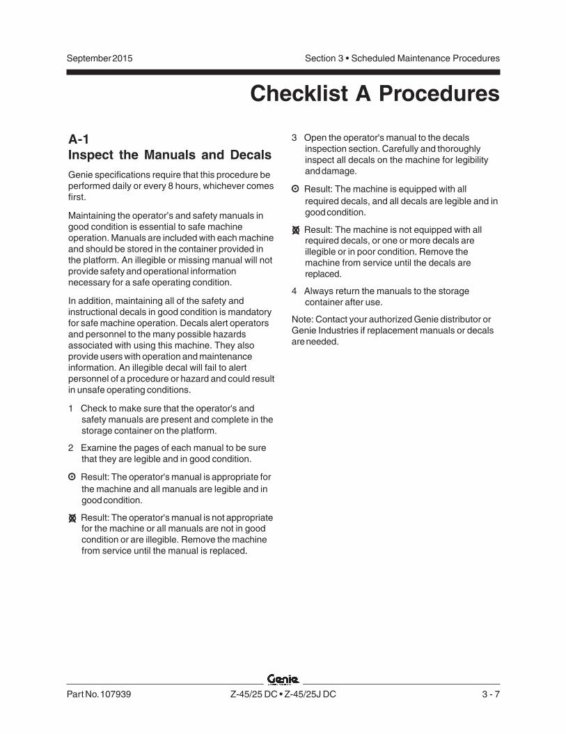
Secondary Boom Components
5-1 Secondary Boom........................................................................................ 4 - 23
5-2 Secondary Boom Lift Cylinders .................................................................. 4 - 28
Hydraulic Pumps
6-1 Auxiliary and Function Pump...................................................................... 4 - 29

Z-45/25 DC • Z-45/25J DC Part No. 107939
September 2015
TABLE OF CONTENTS
xii
Section 4 Repair Procedures, continued
Manifolds
7-1 Function Manifold Components .................................................................. 4 - 30
7-2 Valve Adjustments - Function Manifold ...................................................... 4 - 32
7-3 Jib Boom / Platform Rotate Manifold Components ..................................... 4 - 33
7-4 Turntable Rotation Manifold Components ................................................... 4 - 34
7-5 Valve Coils ................................................................................................. 4 - 35
Turntable Rotation Components
8-1 Turntable Rotation Assembly ..................................................................... 4 - 37
Motor Controller
9-1 Motor Controller .......................................................................................... 4 - 38
Section 5 Fault Codes
Introduction ............................................................................................................ 5 - 1
Fault Code Chart .................................................................................................... 5 - 3
Section 6 Schematics
Introduction ............................................................................................................ 6 - 1
Electrical Symbols Legend .................................................................................... 6 - 2
Hydraulic Symbols Legend .................................................................................... 6 - 3
Electrical Schematic, Z-45/25 and Z-45/25J, ANSI • CSA • AS(before serial number 31015) ........................................................................ 6 - 6
Ground Control Box Terminal Strip Wiring Diagram, Z-45/25 and Z-45/25J,ANSI • CSA • AS (before serial number 31015) .......................................... 6 - 10
Ground Control Box Switch Panel Wiring Diagram, Z-45/25 and Z-45/25J,ANSI • CSA • AS (before serial number 31015) .......................................... 6 - 11
Platform Control Box Wiring Diagram, Z-45/25 and Z-45/25J,ANSI • CSA • AS (before serial number 31015) .......................................... 6 - 13

Part No. 107939 Z-45/25 DC • Z-45/25J DC
September 2015
TABLE OF CONTENTS
xiii
Section 6 Schematics, continued
Electrical Schematic, Z-45/25 and Z-45/25J, CE(before serial number 31015) ...................................................................... 6 - 16
Ground Control Box Terminal Strip Wiring Diagram, Z-45/25 and Z-45/25J, CE(before serial number 31015) ...................................................................... 6 - 20
Ground Control Box Switch Panel Wiring Diagram, Z-45/25 and Z-45/25J, CE(before serial number 31015) ...................................................................... 6 - 21
Platform Control Box Wiring Diagram, Z-45/25 and Z-45/25J, CE(before serial number 31015) ...................................................................... 6 - 23
Electrical Schematic, Z-45/25 and Z-45/25J, ANSI • CSA • AS(from serial number 31015 to 39313) .......................................................... 6 - 26
Ground Control Box Terminal Strip Wiring Diagram, Z-45/25 and Z-45/25J,ANSI • CSA • AS (from serial number 31015 to 39313) .............................. 6 - 30
Ground Control Box Switch Panel Wiring Diagram, Z-45/25 and Z-45/25J,ANSI •CSA • AS (from serial number 31015 to 39313) ............................... 6 - 31
Platform Control Box Wiring Diagram, Z-45/25 and Z-45/25J,ANSI • CSA • AS (from serial number 31015 to 39313) .............................. 6 - 33
Electrical Schematic, Z-45/25 and Z-45/25J, CE(from serial number 31015 to 39313) .......................................................... 6 - 36
Ground Control Box Terminal Strip Wiring Diagram, Z-45/25 and Z-45/25J, CE(from serial number 31015 to 39313) .................................................................... 6 - 40
Ground Control Box Switch Panel Wiring Diagram, Z-45/25 and Z-45/25J, CE(from serial number 31015 to 39313) .................................................................... 6 - 41
Platform Control Box Wiring Diagram, Z-45/25 and Z-45/25J, CE(from serial number 31015 to 39313) .......................................................... 6 - 43
Electrical Schematic, Z-45/25 and Z-45/25J, ANSI • CSA • AS(after serial number 39313) ......................................................................... 6 - 46
Ground Control Box Terminal Strip Wiring Diagram, Z-45/25 and Z-45/25J,ANSI • CSA • AS (after serial number 39313) ............................................ 6 - 50
Ground Control Box Switch Panel Wiring Diagram, Z-45/25 and Z-45/25J,ANSI •CSA • AS (after serial number 39313).............................................. 6 - 51
Platform Control Box Wiring Diagram, Z-45/25 and Z-45/25J,ANSI • CSA • AS (after serial number 39313) ............................................ 6 - 53

Z-45/25 DC • Z-45/25J DC Part No. 107939
September 2015
xiv
Section 6 Schematics, continued
Electrical Schematic, Z-45/25 and Z-45/25J, CE(after serial number 39313) ......................................................................... 6 - 56
Ground Control Box Terminal Strip Wiring Diagram, Z-45/25 and Z-45/25J, CE(after serial number 39313) ......................................................................... 6 - 60
Ground Control Box Switch Panel Wiring Diagram, Z-45/25 and Z-45/25J, CE(after serial number 39313) ......................................................................... 6 - 61
Platform Control Box Wiring Diagram, Z-45/25 and Z-45/25J, CE(after serial number 39313) ......................................................................... 6 - 64
Power Cable Wiring Diagram ................................................................................ 6 - 65
CTE Option, CE ................................................................................................... 6 - 68
Charger Interlock Option ...................................................................................... 6 - 69
Platform Control Box LVI / BCI Option Wiring Diagram(before serial number 31015) ...................................................................... 6 - 72
Platform Control Box LVI / BCI Option Wiring Diagram(after serial number 31014) ......................................................................... 6 - 73
Hydraulic Schematic ............................................................................................ 6 - 75
TABLE OF CONTENTS

Part No. 107939 Z-45/25 DC • Z-45/25J DC 2 - 1
Section 2 • SpecificationsSeptember 2015
Specifications
Machine Specifications
Tires and wheels
Wheel diameter 14.5 inches
Wheel width 7 inches
Wheel lugs 9 @ 5/8 -18
Lug nut torque, lubricated 94 ft-lbs127.5 Nm
Lug nut torque, dry 125 ft-lbs169.5 Nm
Tire size 9-14.5 LT
Tire ply rating Tread 8Sidewall 6
Tire weight, new foam-filled (minimum) 175 lbs79 kg
Tire contact area 43.5 sq in280 sq cm
Overall tire diameter 28 in71 cm
For operational specifications, refer to theOperator's Manual.
Fluid capacities
Hydraulic tank 8 gallons30.3 liters
Hydraulic system 11 gallons(including tank) 41.6 liters
Drive hubs (refer to tag on drive hub to determine type)EW1 type 17 fl oz
0.51 literW1 type 23 fl oz
0.68 liter
Drive hub oil type: EP 80-90W gear oilAPI service classification GL5
Batteries
Type 6V DC
Quantity 8
Capacity 350 AH
Reserve capacity @ 25A rate 750 minutes
Weight, each 106 lbs48 kg

2 - 2 Z-45/25 DC • Z-45/25J DC Part No. 107939
Section 2 • Specifications September 2015
SPECIFICATIONS
Performance Specifications
Drive speeds, maximum
Drive speed, stowed 3 mphAll models 4.8 km/h
40 ft/9 sec12.2 m/9 sec
Drive speed, boom 0.6 mphraised or extended, 1 km/hall models 40 ft/45 sec
12.2 m/45 sec
Braking distance, maximum
High range on paved surface 5 to 7 ft1.5 to 2 m
Gradeability See Operator's Manual
Boom function speeds, maximumfrom platform controls
Jib boom up, Z-45/25J 26 to 40 seconds
Jib boom down, Z-45/25J 22 to 28 seconds
Primary boom up 32 to 40 seconds
Primary boom down 26 to 30 seconds
Secondary boom up 38 to 46 seconds
Secondary boom down 38 to 46 seconds
Primary boom extend 14 to 18 seconds
Primary boom retract 17 to 21 seconds
Turntable rotate, 355° 95 to 125 secondsprimary boom retracted
Platform rotate, 180°, Z-45/25 6 to 10 seconds
Platform rotate, 160°, Z-45/25J 6 to 10 seconds

Part No. 107939 Z-45/25 DC • Z-45/25J DC 2 - 3
Section 2 • SpecificationsSeptember 2015
Hydraulic Specifications
Hydraulic Oil Specifications
Hydraulic oil type Chevron Rykon MV equivalentApproximate SAE grade 5W-20Viscosity index rating 200
Cleanliness level, minimum 15/13
Water content, maximum 200 ppm
Chevron Rando HD MV oil is fully compatible andmixable with Shell Donax TG (Dexron III) oils.Genie specifications require hydraulic oils which aredesigned to give maximum protection to hydraulicsystems, have the ability to perform over a widetemperature range, and the viscosity index shouldexceed 140. They should provide excellent antiwear,oxidation, corrosion inhibition, seal conditioning, andfoam and aeration suppression properties.
Optional fluids
Biodegradable Petro Canada Environ MV46Statoil Hydra Way Bio Pa 32
BP Biohyd SE-S
Fire resistant UCON Hydrolube HP-5046Quintolubric 822
Mineral based Shell Tellus T32Shell Tellus T46
Chevron Aviation A
Continued use of Chevron AviationA hydraulic oil when ambienttemperatures are consistentlyabove 32°F / 0°C may result incomponent damage.
Note: Use Chevron Aviation A hydraulic oil whenambient temperatures consistently below0°F / -18°C.
Note: Use Shell Tellus T46 hydraulic oil when oiltemperatures consistently exceed 205°F / 96°C.
Note: Genie specifications require additionalequipment and special installation instructions forthe approved optional fluids. Consult the GenieIndustries Service Department before use.
Function pump
Type: Fixed displacement gear pump
Displacement 0.183 cu in3 cc
Flow rate 2.1 gpm7.9 L/min
Hydraulic tank 10 micron withreturn filter 25 psi / 1.7 bar bypass
Function manifold
Function relief valve pressure 3200 psi220.6 bar
Secondary boom down 2100 psirelief valve pressure 145 bar
Platform level flow regulator 0.6 gpm2.27 L/min
Jib boom/platform rotate flow regulator 0.4 gpm1.5 L/min
Auxiliary pump
Type: Fixed displacement gear pump
Displacement 0.5 gpm1.9 L/min
SPECIFICATIONS

2 - 4 Z-45/25 DC • Z-45/25J DC Part No. 107939
Section 2 • Specifications September 2015
Manifold ComponentSpecifications
Plug torque
SAE No. 2 36 in-lbs / 4 Nm
SAE No. 4 10 ft-lbs / 13 Nm
SAE No. 6 14 ft-lbs / 19 Nm
SAE No. 8 38 ft-lbs / 51 Nm
SAE No. 10 41 ft-lbs / 55 Nm
SAE No. 12 56 ft-lbs / 76 Nm
Valve Coil Resistance Specification
Solenoid valve, 3 position 4 way, 20V DC 25 to 29 Ω(schematic items B, C, D, E, F and H)
Solenoid valve, 2 position 3 way, 20V DC 25 to 29 Ω(schematic items A, K, S and AA)
Proportional solenoid valve, 24V DC 17 to 21 Ω(schematic item I)
SPECIFICATIONS
Machine Torque Specifications
Platform rotator
3/4 -10 center bolt, GR 8 380 ft-lbs515 Nm
3/8 -16 bolts, GR 8 44 ft-lbs60 Nm
Turntable rotate assembly
Rotate bearing mounting bolts, lubricated 180 ft-lbs244 Nm
Drive motor/brake mounting bolts, dry 110 ft-lbs149 Nm
Drive motor/brake mounting bolts, lubricated 80 ft-lbs108 Nm
Drive motor and hubs
Drive hub mounting bolts, lubricated 180 ft-lbs244 Nm
Drive motor mounting bolts, lubricated 55 ft-lbs75 Nm

Part No. 107939 Z-45/25 DC • Z-45/25J DC 2 - 5
Section 2 • SpecificationsSeptember 2015
SPECIFICATIONS
Hydraulic Hose and FittingTorque SpecificationsYour machine is equipped with Parker Seal-Lok®fittings and hose ends. Genie specifications requirethat fittings and hose ends be torqued tospecification when they are removed and installedor when new hoses or fittings are installed.
SAE O-ring Boss Port(tube fitting - installed into Aluminum)
SAE Dash size Torque
-4 11 ft-lbs / 14.9 Nm
-6 23 ft-lbs / 31.2 Nm
-8 40 ft-lbs / 54.2 Nm
-10 69 ft-lbs / 93.6 Nm
-12 93 ft-lbs / 126.1 Nm
-16 139 ft-lbs / 188.5 Nm
-20 172 ft-lbs / 233.2 Nm
-24 208 ft-lbs / 282 Nm
SAE O-ring Boss Port(tube fitting - installed into Steel)
SAE Dash size Torque
-4 16 ft-lbs / 21.7 Nm
-6 35 ft-lbs / 47.5 Nm
-8 60 ft-lbs / 81.3 Nm
-10 105 ft-lbs / 142.4 Nm
-12 140 ft-lbs / 190 Nm
-16 210 ft-lbs / 284.7 Nm
-20 260 ft-lbs / 352.5 Nm
-24 315 ft-lbs / 427.1 Nm
Seal-Lok® Fittings(hose end)
SAE Dash size Torque
-4 18 ft-lbs / 25 Nm
-6 30 ft-lbs / 40 Nm
-8 40 ft-lbs / 55 Nm
-10 60 ft-lbs / 80 Nm
-12 85 ft-lbs / 115 Nm
-16 110 ft-lbs / 150 Nm
-20 140 ft-lbs / 190 Nm
-24 180 ft-lbs / 245 Nm
Seal-Lok® fittings
1 Replace the O-ring. The O-ring must be replacedanytime the seal has been broken. The O-ringcannot be re-used if the fitting or hose end hasbeen tightened beyond finger tight.
Note: The O-rings used in the Parker Seal Lok®fittings and hose ends are custom-size O-rings.They are not standard SAE size O-rings. They areavailable in the O-ring field service kit (Genie partnumber 49612).
2 Lubricate the O-ring before installation.
3 Be sure that the face seal O-ring is seated andretained properly.
4 Position the tube and nut squarely on the faceseal end of the fitting and tighten the nut fingertight.
5 Tighten the nut or fitting to the appropriatetorque per given size as shown in the table.
6 Operate all machine functions and inspect thehoses and fittings and related components toconfirm that there are no leaks.

2 - 6 Z-45/25 DC • Z-45/25J DC Part No. 107939
Section 2 • Specifications September 2015
SPECIFICATIONS
Size
(mm)in- lbs N m in-lbs N m in- lbs N m in- lbs N m in- lbs N m in- lbs N m in- lbs N m in- lbs N m
5 16 1.8 21 2.4 41 4.63 54 6.18 58 6.63 78 8.84 68 7.75 91 10.36 19 3.05 36 4.07 69 7.87 93 10.5 100 11.3 132 15 116 13.2 155 17.67 45 5.12 60 6.83 116 13.2 155 17.6 167 18.9 223 25.2 1.95 22.1 260 29.4
f t - lbs N m ft-lbs N m ft- lbs N m ft- lbs N m ft- lbs N m ft- lbs N m ft- lbs N m ft- lbs N m
8 5.4 7.41 7.2 9.88 14 19.1 18.8 25.5 20.1 27.3 26.9 36.5 23.6 32 31.4 42.610 10.8 14.7 14.4 19.6 27.9 37.8 37.2 50.5 39.9 54.1 53.2 72.2 46.7 63.3 62.3 84.412 18.9 25.6 25.1 34.1 48.6 66 64.9 88 69.7 94.5 92.2 125 81 110 108 14714 30.1 40.8 40 54.3 77.4 105 103 140 110 150 147 200 129 175 172 23416 46.9 63.6 62.5 84.8 125 170 166 226 173 235 230 313 202 274 269 36518 64.5 87.5 86.2 117 171 233 229 311 238 323 317 430 278 377 371 50320 91 124 121 165 243 330 325 441 337 458 450 610 394 535 525 71322 124 169 166 225 331 450 442 600 458 622 612 830 536 727 715 97024 157 214 210 285 420 570 562 762 583 791 778 1055 682 925 909 1233
LUBED DRY LUBED DRYLUBED DRY LUBED DRY
LUBEDDRYLUBED
Class 12.9Class 4.6
DRYLUBED
METRIC FASTENER TORQUE CHART• This chart is to be used as a guide only unless noted elsewhere in this manual •
LUBED DRY
Class 10.9Class 8.8
DRY
SIZE THREAD
in-lbs Nm in-lbs Nm in-lbs Nm in-lbs Nm in-lbs Nm
20 80 9 100 11.3 110 12.4 140 15.8 130 14.728 90 10.1 120 13.5 120 13.5 160 18 140 15.8
ft-lbs Nm ft-lbs Nm ft-lbs Nm ft-lbs Nm ft-lbs Nm18 13 17.6 17 23 18 24 25 33.9 21 28.424 14 19 19 25.7 20 27.1 27 36.6 24 32.516 23 31.2 31 42 33 44.7 44 59.6 38 51.524 26 35.2 35 47.4 37 50.1 49 66.4 43 58.314 37 50.1 49 66.4 50 67.8 70 94.7 61 82.720 41 55.5 55 74.5 60 81.3 80 108.4 68 92.113 57 77.3 75 101.6 80 108.4 110 149 93 12620 64 86.7 85 115 90 122 120 162 105 14212 80 108.4 110 149 120 162 150 203 130 17618 90 122 120 162 130 176 170 230 140 18911 110 149 150 203 160 217 210 284 180 24418 130 176 170 230 180 244 240 325 200 27110 200 271 270 366 280 379 380 515 320 43316 220 298 300 406 310 420 420 569 350 4749 320 433 430 583 450 610 610 827 510 69114 350 474 470 637 500 678 670 908 560 7598 480 650 640 867 680 922 910 1233 770 104412 530 718 710 962 750 1016 990 1342 840 11397 590 800 790 1071 970 1315 1290 1749 1090 147712 670 908 890 1206 1080 1464 1440 1952 1220 16547 840 1138 1120 1518 1360 1844 1820 2467 1530 207412 930 1260 1240 1681 1510 2047 2010 2725 1700 23046 1460 1979 1950 2643 2370 3213 3160 4284 2670 362012 1640 2223 2190 2969 2670 3620 3560 4826 3000 4067
5/16
3/8
7/16
1/2
1 1/2
9/16
5/8
3/4
7/8
1
1 1/8
1 1/4
LUBED
1/4
LUBED DRY LUBED DRY
LUBEDDRYLUBED
SAE FASTENER TORQUE CHART
Grade 5
DRYLUBED
• This chart is to be used as a guide only unless noted elsewhere in this manual •A574 High Strength Black Oxide BoltsGrade 8
10.9 12.98.84.6

Part No. 107939 Z-45/25 DC • Z-45/25J DC 3 - 1
September 2015 Section 3 • Scheduled Maintenance Procedures
About This Section
This section contains detailed procedures for eachscheduled maintenance inspection.
Each procedure includes a description, safetywarnings and step-by-step instructions.
Symbols Legend
Safety alert symbol—used to alertpersonnel to potential personalinjury hazards. Obey all safetymessages that follow this symbolto avoid possible injury or death.
Indicates an imminently hazardoussituation which, if not avoided, willresult in death or serious injury.
Indicates a potentially hazardoussituation which, if not avoided,could result in death or seriousinjury.
Indicates a potentially hazardoussituation which, if not avoided,may cause minor or moderateinjury.
Indicates a potentially hazardoussituation which, if not avoided,may result in property damage.
Indicates that a specific result is expected afterperforming a series of steps.
Indicates that an incorrect result has occurredafter performing a series of steps.
Scheduled Maintenance Procedures
Observe and Obey:
Maintenance inspections shall be completed bya person trained and qualified on themaintenance of this machine.
Scheduled maintenance inspections shall becompleted daily, quarterly, semi-annually,annually and every 2 years as specified on theMaintenance Inspection Report. The frequencyand extent of periodic examinations and testsmay also depend on national regulations.
Failure to properly complete eachinspection when required maycause death, serious injury orsubstantial machine damage.
Immediately tag and remove from service adamaged or malfunctioning machine.
Repair any machine damage or malfunctionbefore operating the machine.
Unless otherwise specified, perform eachprocedure with the machine in the followingconfiguration:
• Machine parked on a firm, level surface
• Boom in the stowed position
• Turntable rotated with the boom betweenthe non-steer wheels
• Turntable secured with the turntablerotation lock
• Key switch in the off position with thekey removed
• Wheels chocked
• All external AC power supply disconnected from the machine

3 - 2 Z-45/25 DC • Z-45/25J DC Part No. 107939
September 2015Section 3 • Scheduled Maintenance Procedures
Maintenance Symbols Legend
The following symbols have been used in thismanual to help communicate the intent of theinstructions. When one or more of the symbolsappear at the beginning of a maintenanceprocedure, it conveys the meaning below.
Indicates that tools will be required toperform this procedure.
Indicates that new parts will be requiredto perform this procedure.
Indicates that a cold motor or pump willbe required to perform this procedure.
Indicates that a warm motor or pump willbe required to perform this procedure.
Indicates that dealer service will berequired to perform this procedure.
Maintenance Schedule
There are five types of maintenance inspectionsthat must be performed according to a schedule—daily, quarterly, six months, annual, and two year.The Scheduled Maintenance Procedures Sectionand the Maintenance Inspection Report have beendivided into five subsections—A, B, C, D and E.Use the following chart to determine which group(s)of procedures are required to perform a scheduledinspection.
Inspection Checklist
Daily or every 8 hours A
Quarterly or every 250 hours A + B
Six months or every 500 hours A + B + C
Annual or every 1000 hours A + B + C + D
Two year or every 2000 hours A + B + C + D + E
Maintenance Inspection Report
The maintenance inspection report containschecklists for each type of scheduled inspection.
Make copies of the Maintenance Inspection Reportto use for each inspection. Maintain completedforms for a minimum of 4 years or in compliancewith employer, jobsite and govermental regulationsand requirements.
SCHEDULED MAINTENANCE PROCEDURES

Part No. 107939 Z-45/25 DC • Z-45/25J DC 3 - 3
September 2015 Section 3 • Scheduled Maintenance Procedures
Genie Industries USA18340 NE 76th StreetPO Box 97030Redmond, WA 98073-9730(425) 881-1800
Copyright © 2002 by Genie Industries. Genie® is a registered trademark of Genie Industries.Rev B
Genie UKThe Maltings, Wharf Road
Grantham, LincolnshireNG31- 6BH England
(44) 1476-584333
Pre-DeliverPre-DeliverPre-DeliverPre-DeliverPre-Delivery Preparationy Preparationy Preparationy Preparationy Preparation
Pre-Delivery Preparation Y N R
Pre-operation inspection completed
Maintenance items completed
Function tests completed
Model
Serial number
Date
Machine owner
Inspected by (print)
Inspector signature
Inspector title
Inspector company
Instructions
Use the operator’s manual on your machine.
The Pre-delivery Preparation consists of completing thePre-operation Inspection, the Maintenance items and theFunction Tests.
Use this form to record the results. Place a check in theappropriate box after each part is completed. Follow theinstructions in the operator’s manual.
If any inspection receives an N, remove the machine fromservice, repair and re-inspect it. After repair, place a checkin the R box.
LegendY = yes, completedN = no, unable to completeR = repaired
Comments
Fundamentals
It is the responsibility of the dealer to perform thePre-delivery Preparation.
The Pre-delivery Preparation is performed prior to eachdelivery. The inspection is designed to discover if anythingis apparently wrong with a machine before it is put intoservice.
A damaged or modified machine must never be used. Ifdamage or any variation from factory delivered condition isdiscovered, the machine must be tagged and removedfrom service.
Repairs to the machine may only be made by a qualifiedservice technician, according to the manufacturer'sspecifications.
Scheduled maintenance inspections shall be performed byqualified service technicians, according to themanufacturer's specifications and the requirements listedin the responsibilities manual.

3 - 4 Z-45/25 DC • Z-45/25J DC Part No. 107939
September 2015Section 3 • Scheduled Maintenance Procedures
This page intentionally left blank.

Part No. 107939 Z-45/25 DC • Z-45/25J DC 3 - 5
September 2015 Section 3 • Scheduled Maintenance Procedures
Checklist A Y N R
A-1 Manuals and Decals
A-2 Pre-operationinspection
A-3 Function tests
Perform after 40 hours:
A-4 30 Day Service
Perform every 100 hours:
A-5 Grease rotationbearing
Perform after 150 hours:
A-6 Replace drive hub oil
Checklist B Y N R
B-1 Batteries
B-2 Electrical wiring
B-3 Key Switch
B-4 Tires and wheels
B-5 Brake configuration
B-6 Drive hub oil level
B-7 Ground controloverride
B-8 Platform leveling
B-9 Drive brakes
B-10 Drive speed - stowed
B-11 Drive speed - raised
B-12 Alarm package(if equipped)
B-13 Turntable rotation stop
B-14 Electrical contactors
B-15 Hydraulic oil analysis
B-16 Emergency power
Checklist C Y N R
C-1 Grease platformoverload (if equipped)
C-2 Test platformoverload (if equipped)
Checklist D Y N R
D-1 Boom wear pads
D-2 Turntable bearing bolts
D-3 Free-wheelconfiguration
D-4 Drive hub oil
D-5 Hydraulic return filter
D-6 Turntable bearing wear
Checklist E Y N R
E-1 Hydraulic oil
E-2 Wheel bearings
Instructions• Make copies of this page to use for
each inspection.
• Select the appropriate checklist(s) forthe type of inspection to beperformed.
Daily or 8 hourInspection: A
Quarterly or 250 hourInspection: A+B
Semi-annual or 500 hourInspection: A+B+C
Annual or 1000 hoursInspection: A+B+C+D
2 Year or 2000 hourInspection: A+B+C+D+E
• Place a check in the appropriate boxafter each inspection procedure iscompleted.
• Use the step-by-step procedures inthis section to learn how to performthese inspections.
• If any inspection receives an “N”, tagand remove the machine fromservice, repair and re-inspect it. Afterrepair, place a check in the “R” box.
LegendY = yes, acceptableN = no, remove from serviceR = repaired
Maintenance Inspection Report
Model
Serial number
Date
Hour meter
Machine owner
Inspected by (print)
Inspector signature
Inspector title
Inspector company
Comments

3 - 6 Z-45/25 DC • Z-45/25J DC Part No. 107939
September 2015Section 3 • Scheduled Maintenance Procedures
This page intentionally left blank.
Part No. 107939 Z-45/25 DC • Z-45/25J DC 3 - 7
September 2015 Section 3 • Scheduled Maintenance Procedures
A-1Inspect the Manuals and DecalsGenie specifications require that this procedure beperformed daily or every 8 hours, whichever comesfirst.
Maintaining the operator’s and safety manuals ingood condition is essential to safe machineoperation. Manuals are included with each machineand should be stored in the container provided inthe platform. An illegible or missing manual will notprovide safety and operational informationnecessary for a safe operating condition.
In addition, maintaining all of the safety andinstructional decals in good condition is mandatoryfor safe machine operation. Decals alert operatorsand personnel to the many possible hazardsassociated with using this machine. They alsoprovide users with operation and maintenanceinformation. An illegible decal will fail to alertpersonnel of a procedure or hazard and could resultin unsafe operating conditions.
1 Check to make sure that the operator's andsafety manuals are present and complete in thestorage container on the platform.
2 Examine the pages of each manual to be surethat they are legible and in good condition.
Result: The operator's manual is appropriate forthe machine and all manuals are legible and ingood condition.
Result: The operator's manual is not appropriatefor the machine or all manuals are not in goodcondition or are illegible. Remove the machinefrom service until the manual is replaced.
3 Open the operator's manual to the decalsinspection section. Carefully and thoroughlyinspect all decals on the machine for legibilityand damage.
Result: The machine is equipped with allrequired decals, and all decals are legible and ingood condition.
Result: The machine is not equipped with allrequired decals, or one or more decals areillegible or in poor condition. Remove themachine from service until the decals arereplaced.
4 Always return the manuals to the storagecontainer after use.
Note: Contact your authorized Genie distributor orGenie Industries if replacement manuals or decalsare needed.
Checklist A Procedures

3 - 8 Z-45/25 DC • Z-45/25J DC Part No. 107939
September 2015Section 3 • Scheduled Maintenance Procedures
A-2Perform Pre-operationInspectionGenie specifications require that this procedure beperformed daily or every 8 hours, whichever comesfirst.
Completing a pre-operation inspection is essentialto safe machine operation. The pre-operationinspection is a visual inspection performed by theoperator prior to each work shift. The inspection isdesigned to discover if anything is apparently wrongwith a machine before the operator performs thefunction tests. The pre-operation inspection alsoserves to determine if routine maintenanceprocedures are required.
Complete information to perform this procedure isavailable in the appropriate operator's manual. Referto the Operator's Manual on your machine.
A-3Perform Function TestsGenie specifications require that this procedure beperformed daily or every 8 hours, whichever comesfirst.
Completing the function tests is essential to safemachine operation. Function tests are designed todiscover any malfunctions before the machine isput into service. A malfunctioning machine mustnever be used. If malfunctions are discovered, themachine must be tagged and removed fromservice.
Complete information to perform this procedure isavailable in the appropriate operator's manual. Referto the Operator's Manual on your machine.
CHECKLIST A PROCEDURES

Part No. 107939 Z-45/25 DC • Z-45/25J DC 3 - 9
September 2015 Section 3 • Scheduled Maintenance Procedures
A-4Perform 30 Day Service
The 30 day maintenance procedure is a one-timesequence of procedures to be performed after thefirst 30 days or 40 hours of usage. After thisinterval, refer to the maintenance checklists forcontinued scheduled maintenance.
1 Perform the following maintenance procedures:
• A-5 Grease the Turntable RotationBearing and Worm Drive Gear
• B-4 Check the Tires, Wheels and Lug NutTorque
• D-2 Check the Turnable RotationBearing Bolts
• D-5 Replace the Hydraulic TankReturn Filter Element
A-5Grease the Turntable RotationBearing and Rotate Gear
Genie specifications require that this procedure beperformed every 100 hours.
Frequent application of lubrication to the turntablebearing and rotate drive gear is essential to goodmachine performance and service life. Continueduse of an insufficently greased gear will result incomponent damage.
1 Before serial number 27001: Locate the greasefitting on the front turntable cover.
After serial number 27000: Locate the greasefitting near the ground control box.
2 Pump grease into the turntable rotation bearing.Rotate the turntable in increments of4 to 5 inches / 10 to 13 cm at a time and repeatthis step until the entire bearing has beengreased.
3 Apply grease to each tooth of the drive gear,located under the turntable.
Grease Specification
Chevron Ultra-duty grease, EP NLGI 2 (lithium based)or equivalent
CHECKLIST A PROCEDURES

3 - 10 Z-45/25 DC • Z-45/25J DC Part No. 107939
September 2015Section 3 • Scheduled Maintenance Procedures
A-6Replace the Drive Hub Oil
Manufacturer drive hub specifications require thatthis one-time procedure be performed after the first150 hours.
Replacing the drive hub oil is essential for goodmachine performance and service life. Failure toreplace the drive hub oil after the first 150 hours ofuse may cause the machine to perform poorly andcontinued use may cause component damage.
1 Select the drive hub to be serviced. Drive themachine until one of the two plugs is at thelowest point.
2 Remove both plugs and drain the oil into asuitable container.
3 Drive the machine until one plug is at the topand the other is at 90 degrees.
a drive hub plugs
4 Fill the hub with oil from the top hole until the oillevel is even with the bottom of the side plughole. Refer to Section 2, Specifications.
5 Install the plugs into the drive hub.
6 Repeat this procedure for the other drive hub.
a
CHECKLIST A PROCEDURES

Part No. 107939 Z-45/25 DC • Z-45/25J DC 3 - 11
September 2015 Section 3 • Scheduled Maintenance Procedures
B-1Check the Batteries
Genie specifications require that this procedure beperformed every 250 hours or quarterly, whichevercomes first.
Proper battery condition is essential to goodmachine performance and operational safety.Improper fluid levels or damaged cables andconnections can result in component damage andhazardous conditions.
Electrocution/burn hazard. Contactwith hot or live circuits could resultin death or serious injury. Removeall rings, watches and otherjewelry.
Bodily injury hazard. Batteriescontain acid. Avoid spilling orcontacting battery acid. Neutralizebattery acid spills with baking sodaand water.
1 Disconnect each battery pack from the machine.
2 Release the battery pack latches and rotateeach battery pack out and away from thechassis.
3 Remove the cover from each battery box.
4 Be sure that the battery cable connections arefree of corrosion.
Note: Adding terminal protectors and a corrosionpreventative sealant will help eliminate corrosion onthe battery terminals and cables.
5 Be sure that the battery retainers and cableconnections are tight.
6 Fully charge the batteries. Allow the batteries torest 24 hours before continuing this procedure toallow the battery cells to equalize.
7 Put on protective clothing and eye wear.
8 Remove the battery vent caps and check thespecific gravity of each battery cell with ahydrometer. Note the results.
9 Check the ambient air temperature and adjustthe specific gravity reading for each cell asfollows:
• Add 0.004 to the reading of each cell forevery 10° / 5.5° C above 80° F / 26.7° C.
• Subtract 0.004 from the reading of each cell forevery 10° / 5.5° C below 80° F / 26.7° C.
Result: All battery cells display an adjustedspecific gravity of 1.277 or higher. The batteryis fully charged. Proceed to step 13.
Result: One or more battery cells display aspecific gravity of 1.217 or below. Proceed tostep 10.
10 Perform an equalizing charge OR fully chargethe batteries and allow the batteries to rest atleast 6 hours.
11 Remove the battery vent caps and check thespecific gravity of each battery cell with ahydrometer. Note the results.
Checklist B Procedures

3 - 12 Z-45/25 DC • Z-45/25J DC Part No. 107939
September 2015Section 3 • Scheduled Maintenance Procedures
12 Check the ambient air temperature and adjustthe specific gravity reading for each cell asfollows:
• Add 0.004 to the reading of each cell forevery 10° / 5.5° C above 80° F / 26.7° C.
• Subtract 0.004 from the reading of each cell forevery 10° / 5.5° C below 80° F / 26.7° C.
Result: All battery cells display a specificgravity of 1.277 or greater. The battery is fullycharged. Proceed to step 13.
Result: The difference in specific gravityreadings between cells is greater than 0.1 ORthe specific gravity of one or more cells is lessthan 1.217. Replace the battery.
13 Check the battery acid level. If needed,replenish with distilled water to 1/
8 inch / 3 mm
below the bottom of the battery fill tube. Do notoverfill.
14 Install the vent caps and neutralize anyelectrolyte that may have spilled.
B-2Inspect the Electrical Wiring
Genie specifications require that this procedure beperformed every 250 hours or quarterly, whichevercomes first.
Maintaining electrical wiring in good condition isessential to safe operation and good machineperformance. Failure to find and replace burnt,chafed, corroded or pinched wires could result inunsafe operating conditions and may causecomponent damage.
Electrocution/burn hazard. Contactwith hot or live circuits could resultin death or serious injury. Removeall rings, watches and otherjewelry.
1 Inspect the following areas for burnt, chafed,corroded and loose wires:
• Power units
• Inside of the ground control box
• Turntable manifold wiring
2 Inspect for a liberal coating of dielectric greaseat the following location:
• All wire harness connectors to the groundcontrol box
3 Raise the secondary boom until the mid-pivot isapproximately 10 feet / 3 m off the ground.
CHECKLIST B PROCEDURES

Part No. 107939 Z-45/25 DC • Z-45/25J DC 3 - 13
September 2015 Section 3 • Scheduled Maintenance Procedures
CHECKLIST B PROCEDURES
4 Remove the center turntable cover.
5 Inspect the turntable center area for burnt,chafed and pinched cables.
6 Install the center turntable cover.
7 Lower the boom to the stowed position and turnthe machine off.
8 Inspect the following areas for burnt, chafed,corroded, pinched and loose wires:
• Cable track on the primary, jib andsecondary booms
• Jib boom to platform cable harness
• Inside of the platform control box
9 Inspect for a liberal coating of dielectric greaseat the following location:
• All wire harness connectors to the platformcontrol box
B-3Test the Key SwitchGenie specifications require that this procedure beperformed every 250 hours or quarterly, whichevercomes first.
Proper key switch action and response is essentialto safe machine operation. The machine can beoperated from the ground or platform controls andthe activation of one or the other is accomplishedwith the key switch. Failure of the key switch toactivate the appropriate control panel could result ina hazardous operating situation.
1 Pull out the red Emergency Stop button to theon position at both the ground and platformcontrols.
2 Turn the key switch to platform controls.
3 Check the machine functions from the groundcontrols.
Result: The machine functions should notoperate.
4 Turn the key switch to ground controls.
5 Check the machine functions from the platformcontrols.
Result: The machine functions should notoperate.
6 Turn the key switch to the off position.
Result: No function should operate.

3 - 14 Z-45/25 DC • Z-45/25J DC Part No. 107939
September 2015Section 3 • Scheduled Maintenance Procedures
B-5Confirm the ProperBrake Configuration
Genie specifications require that this procedure beperformed every 250 hours or quarterly, whichevercomes first.
Proper brake configuration is essential to safeoperation and good machine performance.Hydraulically released, spring-applied individualwheel brakes can appear to operate normally whenthey are actually not fully operational.
1 Check each drive hub disconnect cap to be sureit is in the engaged position.
brake disengaged position
brake engaged position
B-4Check the Tires, Wheels andLug Nut Torque
Genie specifications require that this procedure beperformed every 250 hours or quarterly, whichevercomes first.
Maintaining the tires and wheels, including properwheel fastener torque, is essential to safe operationand good performance. Tire and/or wheel failurecould result in a machine tip-over. Componentdamage may also result if problems are notdiscovered and repaired in a timely fashion.
1 Check all tire treads and sidewalls for cuts,cracks, punctures and unusual wear.
2 Check each wheel for damage, bends andcracked welds.
3 Check each lug nut for proper torque.Refer to Section 2, Specifications.
CHECKLIST B PROCEDURES

Part No. 107939 Z-45/25 DC • Z-45/25J DC 3 - 15
September 2015 Section 3 • Scheduled Maintenance Procedures
CHECKLIST B PROCEDURES
2 Remove the plug located at 90 degrees andcheck the oil level.
Result: The oil level should be even with thebottom of the plug hole.
3 If necessary, remove the top plug and add oiluntil the oil level is even with the bottom of theplug hole. Refer to Section 2, Specifications.
4 Models with pipe plugs: Apply pipe threadsaelant to the plugs and install the plugs intothe drive hub.
5 Models with O-ring plugs: Install the plugs intothe drive hub.
6 Check the torque of the drive hub bolts.Refer to Section 2, Specifications.
7 Repeat this procedure for each drive hub.
B-6Check the Oil Level in the DriveHubs and Mounting Bolt Torque
Genie specifications require that this procedure beperformed every 250 hours or quarterly, whichevercomes first.
Failure to maintain proper drive hub oil levels,including proper drive hub fastener torque, maycause the machine to perform poorly and continueduse may cause component damage.
1 Drive the machine to rotate the hub until one ofthe plugs is located on top and the other is at90 degrees.
models with pipe plugs
a models with o-ring plugs
a

3 - 16 Z-45/25 DC • Z-45/25J DC Part No. 107939
September 2015Section 3 • Scheduled Maintenance Procedures
B-7Test the Ground ControlOverrideGenie specifications require that this procedure beperformed every 250 hours or quarterly, whichevercomes first.
A properly functioning ground control override isessential to safe machine operation. The groundcontrol override function is intended to allow groundpersonnel to operate the machine from the groundcontrols whether or not the red Emergency Stopbutton on the platform controls is in the on or offposition. This function is particularly useful if theoperator at the platform controls cannot return theboom to the stowed position.
1 Push in the platform red Emergency Stopbutton to the off position.
2 Turn the key switch to ground control and pullout the red Emergency Stop button to the onposition.
3 Operate each boom function through apartial cycle at the ground controls.
Result: All boom functions should operate.
CHECKLIST B PROCEDURES
B-8Test the Platform Self-leveling
Genie specifications require that this procedure beperformed every 250 hours or quarterly, whichevercomes first.
Automatic platform self-leveling throughoutthe full cycle of boom raising and lowering isessential for safe machine operation. Theplatform is maintained level by the platform levelingslave cylinder which is controlled by the platformleveling master cylinder located at the base of theprimary boom. A platform self-leveling failurecreates an unsafe working condition for platformand ground personnel.
1 Turn the key switch to ground control and pullout the red Emergency Stop button to the onposition.
2 Lower the boom to the stowed position.
3 Hold the function enable toggle switch to eitherside and adjust the platform to a level positionusing the platform level toggle switch.
4 Raise and lower the primary boom througha full cycle.
Result: The platform should remain level atall times to within ±5 degrees.

Part No. 107939 Z-45/25 DC • Z-45/25J DC 3 - 17
September 2015 Section 3 • Scheduled Maintenance Procedures
CHECKLIST B PROCEDURES
B-9Test the Drive Brakes
Genie specifications require that this procedure beperformed every 250 hours or quarterly, whichevercomes first.
Proper brake action is essential to safe machineoperation. The drive brake function should operatesmoothly, free of hesitation, jerking and unusualnoise. Hydraulically-released individual wheelbrakes can appear to operate normally when theyare actually not fully operational.
Collision hazard. Be sure that themachine is not in free-wheel orpartial free-wheel configuration.Refer to B-5, Confirm the ProperBrake Configuration.
1 Select a test area that is firm, level and free ofobstructions.
2 Mark a test line on the ground for reference.
3 Lower the boom to the stowed position.
4 Turn the key switch to platform controls.
5 Choose a reference point on the machine; i.e.,contact patch of a tire, as a visual reference foruse when crossing the test line.
6 Bring the machine to top drive speed beforereaching the test line. Release the drive joystickwhen your reference point on the machinecrosses the test line.
7 Measure the distance between the test line andyour machine reference point. Refer toSection 2, Specifications.
Note: The brakes must be able to hold the machineon any slope it is able to climb.
B-10Test the Drive Speed -Stowed Position
Genie specifications require that this procedure beperformed every 250 hours or quarterly, whichevercomes first.
Proper drive function movement is essential to safemachine operation. The drive function shouldrespond quickly and smoothly to operator control.Drive performance should also be free of hesitation,jerking and unusual noise over the entireproportionally controlled speed range.
1 Select a test area that is firm, level and free ofobstructions.
2 Create start and finish lines by marking two lineson the ground 40 feet / 12.2 m apart.
3 Turn the key switch to platform control and pullout the red Emergency Stop button to the onposition at both the ground and platformcontrols.
4 Choose a reference point on the machine; i.e.,contact patch of a tire, as a visual reference foruse when crossing the start and finish lines.
5 Bring the machine to maximum drive speedbefore reaching the start line. Begin timing whenyour reference point on the machine crosses thestart line.
6 Continue at full speed and note the time whenyour machine reference point passes over thefinish line. Refer to Section 2, Specifications.

3 - 18 Z-45/25 DC • Z-45/25J DC Part No. 107939
September 2015Section 3 • Scheduled Maintenance Procedures
CHECKLIST B PROCEDURES
B-11Test the Drive Speed -Raised or Extended Position
Genie specifications require that this procedure beperformed every 250 hours or quarterly, whichevercomes first.
Proper drive function movement is essential to safemachine operation. The drive function shouldrespond quickly and smoothly to operator control.Drive performance should also be free of hesitation,jerking and unusual noise over the entireproportionally controlled speed range.
1 Select a test area that is firm, level and free ofobstructions.
2 Create start and finish lines by marking two lineson the ground 40 feet / 12.2 m apart.
3 Turn the key switch to platform control and pullout the red Emergency Stop button to the onposition at both the ground and platformcontrols.
4 Raise the primary boom more than5 feet / 1.5 m.
5 Choose a reference point on the machine; i.e.,contact patch of a tire, as a visual reference foruse when crossing the start and finish lines.
6 Bring the machine to maximum drive speedbefore reaching the start line. Begin timing whenyour reference point on the machine crosses thestart line.
7 Continue at full speed and note the time whenyour machine reference point passes over thefinish line. Refer to Section 2, Specifications.
B-12Test the Alarm Package(if equipped)Genie specifications require that this procedure beperformed every 250 hours or quarterly, whichevercomes first.
The alarm package includes:
• Travel alarm
• Descent alarm
• Flashing beacon
Alarms and a beacon are installed to alert operatorsand ground personnel of machine proximity andmotion. The alarm package is installed on theground controls side turntable cover.
1 Turn the key switch to ground control and pullout the red Emergency Stop button to the onposition at both the ground and platformcontrols.
Result: The flashing beacon should be on andflashing.
2 Move the function enable switch to either sideand activate the primary boom toggle switch inthe down position, hold for a moment and thenrelease it.
Result: The descent alarm should sound whenthe switch is held down.
3 Move the function enable switch to either sideand activate the secondary boom toggle switchin the down position, hold for a moment andthen release it.
Result: The descent alarm should sound whenthe switch is held down.

Part No. 107939 Z-45/25 DC • Z-45/25J DC 3 - 19
September 2015 Section 3 • Scheduled Maintenance Procedures
B-13Test the Turntable Rotation StopGenie specifications require that this procedure beperformed every 250 hours or quarterly, whichevercomes first.
The turntable is capable of rotating the boom 359degrees and is stopped midpoint between the steerwheels by the rotation stop. Detecting a rotationstop malfunction is essential to safe operation andgood machine performance. If the turntable rotatespast the rotation stop, component damage mayresult.
1 Turn the key switch to platform control and pullout the red Emergency Stop button to the onposition at both the ground and platformcontrols.
2 Rotate the turntable to the left as far as itwill go.
Result: Movement should stop when the primaryboom reaches mid-point between the steer tires.
3 Rotate the turntable to the right full circle as faras it will go.
Result: Movement should stop when theprimary boom reaches mid-point between thesteer tires.
4 Z-45/25J: Move the function enable toggleswitch to either side and activate the jib boomtoggle switch in the down position, hold for amoment and then release it.
Result: The descent alarm should sound whenthe switch is held down.
5 Turn the key switch to platform control.
Result: The flashing beacon should be onand flashing.
6 Press down the foot switch. Activate theprimary boom toggle switch in the downposition, hold for a moment and then release it.
Result: The descent alarm should sound whenthe control handle is held down.
7 Press down the foot switch. Activate thesecondary boom toggle switch in the downposition, hold for a moment and then release it.
Result: The descent alarm should sound whenthe control handle is held down.
8 Z-45/25J: Press down the foot switch. Activatethe jib boom toggle switch in the down position,hold for a moment and then release it.
Result: The descent alarm should sound whenthe switch is held down.
9 Press down the foot switch. Move the drivecontrol handle off center, hold for a momentand then release it. Move the drive controlhandle off center in the opposite direction, holdfor a moment and then release it.
Result: The travel alarm should sound when thedrive control handle is moved off center ineither direction.
CHECKLIST B PROCEDURES

3 - 20 Z-45/25 DC • Z-45/25J DC Part No. 107939
September 2015Section 3 • Scheduled Maintenance Procedures
B-14Check the Electrical Contactors
Genie specifications require that this procedure beperformed every 250 hours or quarterly, whichevercomes first.
Maintaining the electrical contactors in goodcondition is essential to safe machine operation.Failure to locate a worn or damaged contactor couldresult in an unsafe working condition andcomponent damage.
Electrocution/burn hazard. Contactwith hot or live circuits could resultin death or serious injury. Removeall rings, watches and otherjewelry.
1 Remove the drive chassis cover from the non-steer end of the machine and locate theelectrical contactors mounted on the electricalcomponent mounting panel.
2 Visually inspect the contact points of eachcontactor for the following items:
• Excessive burns
• Excessive pitting
Note: Replace the contactors if any damage isfound.
CHECKLIST B PROCEDURES
B-15Perform Hydraulic Oil Analysis
Genie specifications require that this procedure beperformed every 250 hours or quarterly, whichevercomes first.
Replacement or testing of the hydraulic oil isessential for good machine performance andservice life. Dirty oil and suction strainers maycause the machine to perform poorly and continueduse may cause component damage. Extremelydirty conditions may require oil changes to beperformed more often.
Note: Before replacing the hydraulic oil, the oil maybe tested by an oil distributor for specific levels ofcontamination to verify that changing the oil isnecessary. If the hydraulic oil is not replaced atthe two year inspection, test the oil quarterly.Replace the oil when it fails the test. See E-1,Test or Replace the Hydraulic Oil.

Part No. 107939 Z-45/25 DC • Z-45/25J DC 3 - 21
September 2015 Section 3 • Scheduled Maintenance Procedures
B-16Test the Emergency PowerSystem
Genie specifications require that this procedure beperformed every 250 hours or quarterly, whichevercomes first.
Testing the emergency power system is essentialto safe operation if the primary power source fails.
1 Turn the key switch to ground control and pullout the red Emergency Stop button to the onposition at both the ground and platformcontrols.
2 At the ground controls, break the security tieand lift the emergency power switch cover (ifequipped).
3 Simultaneously hold the emergency powerswitch on and activate each boom functiontoggle switch.
Note: To conserve battery power, test eachfunction through a partial cycle.
Result: All boom functions operate.
4 Close the emergency power switch cover andsecure the cover with a security tie (ifequipped).
5 Turn the key switch to platform controls.
6 At the platform controls, break the security tieand lift the emergency power switch cover (ifequipped).
7 Simultaneously hold the emergency powerswitch on and activate each boom function.
Note: To conserve battery power, test eachfunction through a partial cycle.
Result: All boom functions operate.
8 Close the emergency power switch cover andsecure the cover with a security tie (ifequipped).
CHECKLIST B PROCEDURES

3 - 22 Z-45/25 DC • Z-45/25J DC Part No. 107939
September 2015Section 3 • Scheduled Maintenance Procedures
Checklist C Procedures
C-1Grease the Platform OverloadMechanism (if equipped)
Genie specifications require that this procedure beperformed every 500 hours or 6 months, whichevercomes first. Perform this procedure more often ifdusty conditions exist.
Application of lubrication to the platform overloadmechanism is essential to safe machine operation.Continued use of an improperly greased platformoverload mechanism could result in the system notsensing an overloaded platform condition and willresult in component damage.
1 Locate the grease fittings on each pivot pin ofthe platform overload assembly.
2 Thoroughly pump grease into each grease fittingusing a multi-purpose grease.
Grease Specification
Chevron Ultra-duty grease, EP NLGI 2 (lithium based)or equivalent

Part No. 107939 Z-45/25 DC • Z-45/25J DC 3 - 23
September 2015 Section 3 • Scheduled Maintenance Procedures
C-2Test the Platform OverloadSystem (if equipped)
Genie specifications require that this procedure beperformed every 500 hours or six months,whichever comes first.
Testing the platform overload system regularly isessential to safe machine operation. Continued useof an improperly operating platform overloadsystem could result in the system not sensing anoverloaded platform condition. Machine stablitycould be compromised resulting in the machinetipping over.
The platform overload system is designed to detectan overloaded platform and prevent machineoperation anytime the machine is turned on. Whenactivated, the system halts all normal boomoperation, giving visual and audible warning to theoperator.
Models equipped with the platform overload optionare provided with additional machine components:an adjustable spring-loaded platform supportsubassembly, a limit switch, an electronic modulewhich receives the overload signal and interruptspower, and an audio/visual warning indication toalert the operator of the overload.
The platform support subassembly utilizes two loadsupport arms that are opposed in a fullparallelogram link. This isolates platform loads intoa shear or vertical state, which translates into acompressive load. A spring in the parallelogram linksupports this purely compressive load regardless ofwhere the load is placed in the platform.
As weight is added to the platform, the spring willcompress until, when the platform is overloaded,the lower arm contacts a limit switch and therebyactivating the overload signal. When adjustedcorrectly, the platform overload system willdeactivate normal boom operation at platformcapacity.
Note: Perform this procedure with the machine on afirm, level surface.
1 Turn the key switch to platform control. Start theengine and level the platform.
2 Determine the maximum platform capacity.Refer to the machine serial plate.
3 Remove all weight, tools and accessories fromthe platform.
Note: Failure to remove all weight, tools andaccessories from the platform will result in aninaccurate test.
4 Using a suitable lifting device, place a testweight equal to that of the available capacityone of the locations shown.Refer to Illustration 1.
Result: The platform overload indicator lightsshould be off at both the ground and platformcontrols and the alarm should not sound.
Result: The platform overload indicator lights areon and the alarm is sounding. Calibrate theplatform overload system. Refer to RepairProceedure 2-3, How to Calibrate the PlatformOverload System (if equipped).
CHECKLIST C PROCEDURES

3 - 24 Z-45/25 DC • Z-45/25J DC Part No. 107939
September 2015Section 3 • Scheduled Maintenance Procedures
5 Carefully move the test weight to eachremaining location. Refer to Illustration 1.
Result: The platform overload indicator lightsshould be off at both the ground and platformcontrols and the alarm should not sound.
Result: The platform overload indicator lights areon and the alarm is sounding. Calibrate theplatform overload system. Refer to RepairProceedure 2-3, How to Calibrate the PlatformOverload System (if equipped).
Illustration 1
6 Using a suitable lifting device, place anadditional 10 lbs / 4.5 kg of weight onto theplatform.
Result: The alarm should sound.The platform overload indicator lights should beflashing at both the ground and platformcontrols.
Result: The alarm does not sound and theplatform overload indicator lights are notflashing. Calibrate the platform overloadsystem. Refer to Repair Proceedure 2-3,How to Calibrate the Platform Overload System(if equipped).
Note: There may be a 2 second delay before theoverload indicator lights flash and the alarmsounds.
CHECKLIST C PROCEDURES
7 Carefully move the test weights to eachremaining location on the platform.Refer to Illustration 1.
Result: The alarm should sound.The platform overload indicator lights should beflashing at both the ground and platformcontrols.
Result: The alarm does not sound and theplatform overload indicator lights are notflashing. Calibrate the platform overloadsystem. Refer to Repair Proceedure 2-3,How to Calibrate the Platform OverloadSystem (if equipped).
Note: There may be a 2 second delay before theoverload indicator lights flash and the alarmsounds.
8 Test all machine functions from the platformcontrols.
Result: All platform control functions should notoperate.
9 Turn the key switch to ground control.
10 Test all machine functions from the groundcontrols.
Result: All ground control functions should notoperate.
11 Using auxiliary power, test all machine functionsfrom the ground controls.
Result: All ground control functions shouldoperate.

Part No. 107939 Z-45/25 DC • Z-45/25J DC 3 - 25
September 2015 Section 3 • Scheduled Maintenance Procedures
12 Using a suitable lifting device, lift the additionaltest weight from the platform.
Result: The platform overload indicator lightsshould turn off at both the ground and platformcontrols and the alarm should not sound.
Note: There may be an 2 second delay before theoverload indicator lights and alarm turn off.
13 Start the engine and test all machine functionsfrom the ground controls.
Result: All ground control functions shouldoperate normally.
14 Turn the key switch to platform control.
15 Test all machine functions from the platformcontrols.
Result: All platform control functions shouldoperate.
Note: If the platform overload system is notoperating properly, Refer to Repair Procedure 2-3,How to Calibrate the Platform Overload System(if equipped).
16 Using a suitable lifting device, remove theremaining test weights from the platform.
CHECKLIST C PROCEDURES

3 - 26 Z-45/25 DC • Z-45/25J DC Part No. 107939
September 2015Section 3 • Scheduled Maintenance Procedures
D-1Check the Primary BoomWear Pads
Genie specifications require that this procedure beperformed every 1000 hours or annually, whichevercomes first.
Maintaining the primary boom wear pads in goodcondition is essential to safe machine operation.Wear pads are placed on boom tube surfaces toprovide a low friction, replaceable wear padbetween moving parts. Improperly shimmed wearpads or continued use of worn out wear pads mayresult in component damage and unsafe operatingconditions.
1 Measure each wear pad. Replace the wear padonce it reaches the minimum allowablethickness. If the wear pad is still withinspecifications, shim as necessary to obtainminimum clearance with zero binding.
2 Extend and retract the primary boom through theentire range of motion to check for tight spotsthat could cause binding or scraping.
Note: Always maintain squareness between theprimary boom outer and inner tubes.
Primary boom wearpad specifications Minimum
Top, bottom and side wear pads 5/8 inch(platform end of boom) 15.9 mm
Side and bottom wear pads 1/2 inch(pivot end of boom) 12.7 mm
Top wear pads 5/8 inch(pivot end of boom) 15.9 mm
D-2Check the Turntable RotationBearing Bolts
Genie specifications require that this procedure beperformed every 1000 hours or annually, whichevercomes first.
Maintaining proper torque on the turntable bearingbolts is essential to safe machine operation.Improper bolt torque could result in an unsafeoperating condition and component damage
1 Raise the primary boom and place a safetychock on the lift cylinder rod. Carefully lowerthe boom onto the lift cylinder safety chock.
Crushing hazard. Keep handsaway from cylinder and all movingparts when lowering the boom.
Note: A lift cylinder safety chock is availablethrough Genie Service Parts (Genie part no.36555).
Checklist D Procedures

Part No. 107939 Z-45/25 DC • Z-45/25J DC 3 - 27
September 2015 Section 3 • Scheduled Maintenance Procedures
CHECKLIST D PROCEDURES
2 Check to be sure that each turntable mountingbolt is torqued in sequence to specification.Refer to Section 2, Specifications.
Bolt torque sequence(from serial number 23332 to 26999)
Bolt torque sequence(after serial number 26999)
3 Lower the boom to the stowed position.
4 Remove drive chassis covers from both thesteer end and the non-steer end of themachine.
5 Check to be sure that each bearing mountingbolt under the drive chassis is torqued insequence to specification. Refer to Section 2,Specifications.
Bolt torque sequence(after serial number 23332)
15
1013618
311
8
16
2
914 5 17
4
12
7
1
Counterweight
115
7
12
4
5
14
9216
8
3
11
6
1310
Counterweight15
1013618
311
8
16
2
914 5 17
4
12
7
1
1920
Counterweight

3 - 28 Z-45/25 DC • Z-45/25J DC Part No. 107939
September 2015Section 3 • Scheduled Maintenance Procedures
CHECKLIST D PROCEDURES
D-3Check the Free-wheelConfiguration
Genie specifications require that this procedure beperformed every 1000 hours or annually, whichevercomes first.
Proper use of the free-wheel configuration isessential to safe machine operation. Thefree-wheel configuration is used primarily for towing.A machine configured to free-wheel without operatorknowledge may cause death or serious injury andproperty damage.
Collision hazard. Select a work sitethat is firm and level.
Component damage hazard. If themachine must be towed, do notexceed 2 mph / 3.2 km/h.
1 Chock the steer wheels to prevent the machinefrom rolling.
2 Center a lifting jack of ample capacity(15,000 lbs / 7000 kg) under the drive chassis4Disengage the drive hubs by turning over thedrive hub disconnect caps on eachnon-steer wheel hub.
3 Lift the wheels off the ground and place jackstands under the drive chassis for support.
4 Disengage the drive hubs by turning over thedrive hub disconnect caps on eachnon-steer wheel hub.
5 Manually rotate each non-steer wheel.
Result: Each non-steer wheel should rotate withminimum effort.
6 Engage the drive hubs by turning overthe drive hub disconnect caps.
7 Carefully remove the blocks, lower the machineand remove the jack.
Collision hazard. Failure to engagethe drive hubs could result in deathor serious injury and propertydamage.
brake disengagedposition
brake engaged position

Part No. 107939 Z-45/25 DC • Z-45/25J DC 3 - 29
September 2015 Section 3 • Scheduled Maintenance Procedures
CHECKLIST D PROCEDURES
D-4Replace the Drive Hub Oil
Genie specifications require that this procedure beperformed every 1000 hours or annually, whichevercomes first.
Replacing the drive hub oil is essential for goodmachine performance and service life. Failure toreplace the drive hub oil at yearly intervals maycause the machine to perform poorly and continueduse may cause component damage.
1 Select the drive hub to be serviced. Drive themachine until one of the two plugs is at thelowest point.
2 Remove both plugs and drain the oil into asuitable container.
3 Drive the machine until one plug is at the topand the other is at 90 degrees.
models with pipe plugs
a
models with o-ring plugs
4 Fill the hub with oil from the top hole until the oillevel is even with the bottom of the plug hole.Refer to Section 2, Specifications.
5 Models with pipe plugs: Apply pipe threadsealant to the plugs and install the plugs.
Models with O-ring plugs: Install the plugsinto the drive hub.
6 Repeat this procedure for each drive hub.
a

3 - 30 Z-45/25 DC • Z-45/25J DC Part No. 107939
September 2015Section 3 • Scheduled Maintenance Procedures
D-5Replace the Hydraulic TankReturn Filter Element
Genie specifications require that this procedure beperformed every 1000 hours or annually, whichevercomes first. Perform this procedure more often ifdusty conditions exist.
Replacement of the hydraulic return filter element isessential for good machine performance andservice life. A dirty or clogged filter element maycause the machine to perform poorly and continueduse may cause component damage. Extremelydirty conditions may require that the filter elementbe replaced more often.
Bodily injury hazard. Beware of hotoil. Contact with hot oil may causesevere burns.
1 Locate the hydraulic return filter next to thehydraulic tank.
2 Place a suitable container under the hydraulicfilter.
3 Remove the filter with an oil filter wrench.
4 Apply a thin layer of oil to the new oil filtergasket.
5 Install the new filter and tighten it securely byhand. Clean up any oil that may have spilledduring the installation procedure.
6 Turn the key switch to ground controls and pullthe red Emergency Stop button out to the onposition at both the ground and platformcontrols.
7 Activate any boom function and inspect the filterand related components to be sure that thereare no leaks.
8 Use a permanent ink marker to write the dateand number of hours from the hour meter on theoil filter.
CHECKLIST D PROCEDURES
D-6Inspect for Turntable BearingWear
Genie requires that this procedure be performedevery 1000 hours or annually, whichever comesfirst.
Periodic inspection of turntable bearing wear isessential to safe machine operation, good machineperformance and service life. Continued use of aworn turntable bearing could create an unsafeoperating condition, resulting in death or seriousinjury and component damage.
1 Grease the turntable bearing. See A-5, Greasethe Turntable Bearing and Rotate Gear.
2 Torque the turntable bearing bolts tospecification. See D-3, Check the TurntableRotation Bearing Bolts.
3 Raise the primary and secondary booms to fullheight using the ground controls. Do not extendthe primary boom.

Part No. 107939 Z-45/25 DC • Z-45/25J DC 3 - 31
September 2015 Section 3 • Scheduled Maintenance Procedures
4 Place a dial indicator between the drive chassisand the turntable at a point that is directlyunder, or in line with, the boom and no morethan 1 inch / 2.5 cm from the bearing.
Note: To obtain an accurate measurement, placethe dial indicator no more than 1 inch / 2.5 cm fromthe turntable rotation bearing.
a turntableb dial indicatorc drive chassisd turntable rotation bearing
5 Adjust the dial indicator to "0".
6 Lower the secondary boom to the stowedposition and lower the primary boom to ahorizontal position. Fully extend the primaryboom.
7 Note the reading on the dial indicator.
Result: The measurement is less than0.055 inch / 1.4 mm. The bearing is good.
Result: The measurement is more than0.055 inch / 1.4 mm. The bearing is worn andneeds to be replaced.
8 Fully retract the primary boom. Raise theprimary and secondary booms to full height.Visually inspect the the dial indicator to be surethe needle returns to the "0" position.
9 Remove the dial indicator and rotate theturntable 90°.
10 Repeat steps 4 through 9 until the rotationbearing has been checked in at least fourequally spaced areas 90° apart.
11 Lower the primary and secondary booms to thestowed position and turn the machine off.
12 Remove the dial indicator from the machine.
CHECKLIST D PROCEDURES
a
b
c
d

3 - 32 Z-45/25 DC • Z-45/25J DC Part No. 107939
September 2015Section 3 • Scheduled Maintenance Procedures
E-1Test or Replace the Hydraulic Oil
Genie specifications require that this procedure beperformed every 2000 hours or every two years,whichever comes first. Perform this procedure moreoften if dusty conditions exist.
Replacement or testing of the hydraulic oil isessential for good machine performance andservice life. Dirty oil and suction strainers maycause the machine to perform poorly and continueduse may cause component damage. Extremelydirty conditions may require that the oil be changedmore often.
Note: Before replacing the hydraulic oil, the oil maybe tested by an oil distributor for specific levels ofcontamination to verify that changing the oil isnecessary. If the hydraulic oil is not replaced atthe two year inspection, test the oil quarterly.Replace the oil when it fails the test.
Note: When removing a hose assembly or fitting,the O-ring on the fitting and/or hose end must bereplaced and then torqued to specification duringinstallation. Refer to Section 2, Hydraulic Hose andFitting Torque Specifications.
Checklist E Procedures
1 Place a suitable container under the hydraulictank. See capacity specifications.
2 Remove the drain plug from the hydraulic tank.
3 Completely drain the tank into a container ofsuitable capacity. Refer to Section 2,Specifications.
Bodily injury hazard. Beware of hotoil. Contact with hot oil may causesevere burns.
4 Tag, disconnect and plug the hydraulic hosefrom the hydraulic tank filter at the tank.
Bodily injury hazard. Sprayinghydraulic oil can penetrate andburn skin. Loosen hydraulicconnections very slowly to allowthe oil pressure to dissipategradually. Do not allow oil to squirtor spray.
Bodily injury hazard. Beware ofhot oil. Contact with hot oil maycause severe burns.
5 Remove the hydraulic tank mounting fasteners.
6 Pull the hydraulic tank out slightly to access thetwo suction hoses.
7 Tag, disconnect and plug the two suction hoseson the back of the hydraulic tank.
Bodily injury hazard. Sprayinghydraulic oil can penetrate andburn skin. Loosen hydraulicconnections very slowly to allowthe oil pressure to dissipategradually. Do not allow oil to squirtor spray.

Part No. 107939 Z-45/25 DC • Z-45/25J DC 3 - 33
September 2015 Section 3 • Scheduled Maintenance Procedures
8 Remove the hydraulic tank from the machine.
Component damage hazard. Thehydraulic tank is plastic and maybecome damaged if allowed to fall.
9 Remove the suction strainer from the tank andclean it using a mild solvent.
10 Rinse out the inside of the tank using a mildsolvent.
11 Install the suction strainer and drain plug usinga thread sealer on the threads.
12 Place the hydraulic tank onto the machine.
13 Install the hydraulic hoses.
14 Install the hydraulic tank retaining strap.
Component damage hazard. Thehydraulic tank may becomedamaged if the tank strapfasteners are over tightened.
15 Fill the tank with hydraulic oil until the fluid iswithin the FULL and ADD marks on the hydraulictank. Do not overfill.
16 Clean up any oil that may have spilled. Properlydiscard the used oil.
17 Operate all machine functions through a fullcycle and check for leaks.
E-2Grease the Steer AxleWheel Bearings
Genie requires that this procedure be performedevery 2000 hours or every two years, whichevercomes first.
Maintaining the steer axle wheel bearings isessential for safe machine operation and servicelife. Operating the machine with loose or wornwheel bearings may cause an unsafe operatingcondition and continued use may result incomponent damage. Extremely wet or dirtyconditions or regular steam cleaning and pressurewashing of the machine may require that thisprocedure be performed more often.
1 Loosen the wheel lug nuts. Do not remove them.
2 Block the non-steer wheels and center a liftingjack under the steer axle.
3 Raise the machine 6 inches / 15 cm and placeblocks under the drive chassis for support.
4 Remove the lug nuts. Remove the tire and wheelassembly.
5 Check for wheel bearing wear by attempting tomove the wheel hub side to side, then up anddown.
Result: There should be no side to side or upand down movement.
Skip to step 10 if there is no movement.
CHECKLIST E PROCEDURES

3 - 34 Z-45/25 DC • Z-45/25J DC Part No. 107939
September 2015Section 3 • Scheduled Maintenance Procedures
CHECKLIST E PROCEDURES
6 Remove the dust cap from the hub. Remove thecotter pin from the castle nut.
7 Tighten the castle nut to 158 ft-lbs / 214 Nm toseat the bearings.
Note: Rotate the hub by hand while torquing thecastle nut to make sure the bearings seat properly.
8 Loosen the castle nut one full turn and thentorque to 35 ft-lbs / 47 Nm.
9 Check for wheel bearing wear by attempting tomove the wheel hub side to side, then up anddown.
Result: If there is no side to side or up anddown movement, continue with step 10 togrease the wheel bearings.
Result: If there is side to side or up and downmovement, continue to step 10 and replace thewheel bearings with new ones.
Note: When replacing a wheel bearing, both theinner and outer bearings, including the pressed-inraces, must be replaced.
10 Remove the castle nut.
11 Pull the hub off of the spindle. The washer andouter bearing should fall loose from the hub.
12 Place the hub on a flat surface and gently prythe bearing seal out of the hub. Remove the rearbearing.
13 Pack both bearings with clean, fresh grease.
Grease Specification
Chevron Ultra-duty grease, EP NLGI 2 (lithium based)or equivalent
14 Place the large inner bearing into the rear of thehub.
15 Install a new bearing grease seal into the hub bypressing it evenly into the hub until it is flush.
Note: Always replace the bearing grease seal whenthe hub has been removed.
16 Slide the hub onto the yoke spindle.
Component damage hazard. Donot apply excessive force ordamage to the lip of the seal mayoccur.
17 Fill the hub cavity with clean, fresh grease.
18 Place the outer bearing into the hub.
19 Install the washer and castle nut.
20 Tighten the castle nut to 158 ft-lbs / 214 Nm toseat the bearings.
Note: Rotate the hub by hand while torquing thecastle nut to make sure the bearings seat properly.
21 Loosen the castle nut one full turn and thentorque to 35 ft-lbs / 47 Nm.
22 Install a new cotter pin. Bend the cotter pinto lock it in.
Note: Always use a new cotter pin when installing acastle nut.
23 Install the dust cap, then the tire and wheelassembly. Torque the wheel lug nuts tospecification. Refer to Section 2, Specifications.

Part No. 107939 Z-45/25 DC • Z-45/25J DC 4 - 1
September 2015 Section 4 • Repair Procedures
Repair Procedures
Observe and Obey:Repair procedures shall be completed by aperson trained and qualified on the repair of thismachine.
Immediately tag and remove from service adamaged or malfunctioning machine.
Repair any machine damage or malfunctionbefore operating the machine.
Before Repairs Start:Read, understand and obey the safety rules andoperating instructions in the appropriateOperator's Manual on your machine.
Be sure that all necessary tools and parts areavailable and ready for use.
Read each procedure completely and adhereto the instructions. Attempting shortcuts mayproduce hazardous conditions.
Unless otherwise specified, perform eachrepair procedure with the machine in thefollowing configuration:
• Machine parked on a firm, level surface
• Boom in stowed position
• Turntable rotated with the boom between the non-steer wheels
• Turntable secured with the turntable rotation lock
• Key switch in the off position with the key removed
• Wheels chocked
• All external AC power supply disconnectedfrom the machine
About This SectionMost of the procedures in this section should onlybe performed by a trained service professionalin a suitably equipped workshop. Select theappropriate repair procedure after troubleshootingthe problem.
Perform disassembly procedures to the pointwhere repairs can be completed. Then tore-assemble, perform the disassembly steps inreverse order.
Symbols Legend
Safety alert symbol—used to alertpersonnel to potential personalinjury hazards. Obey all safetymessages that follow this symbolto avoid possible injury or death.
Indicates an imminently hazardoussituation which, if not avoided, willresult in death or serious injury.
Indicates a potentially hazardoussituation which, if not avoided,could result in death or seriousinjury.
Indicates a potentially hazardoussituation which, if not avoided,may cause minor or moderateinjury.
Indicates a potentially hazardoussituation which, if not avoided,may result in property damage.
Indicates that a specific result is expected afterperforming a series of steps.
Indicates that an incorrect result has occurredafter performing a series of steps.

4 - 2 Z-45/25 DC • Z-45/25J DC Part No. 107939
September 2015Section 4 • Repair Procedures
1-1Controllers
Platform ControlsThe drive joystick is connected to the drive motorcontroller located under the non-steer end drivechassis cover. The drive motor controller can alsorecognize machine drive malfunctions and displaycontroller fault codes by flashing an LED at theground controls. Refer to Section 5, Fault Codesfor a list of fault codes and additional information.There are no adjustments needed on the drivejoystick controller. For further information orassistance, consult the Genie Industries ServiceDepartment.
a boom function speed controllerb drive joystick
Boom Function SpeedController Adjustments
Electrocution/burn hazard. Contactwith electrically charged circuitscould result in death or seriousinjury. Remove all rings, watchesand other jewelry.
Note: Do not adjust the boom function speedcontroller unless the static battery supply voltage isabove 24V DC.
1 Turn the key switch to platform control and pullout the red Emergency Stop button to the onposition at both the ground and platformcontrols.
2 Open the platform control box lid and locate theboom function speed controller.
a threshold adjustable trimpotb max-out adjustable trimpotc white/red wire to TP6d boom function speed controller
Platform Controls
ab
c
d
b
a

Part No. 107939 Z-45/25 DC • Z-45/25J DC 4 - 3
September 2015 Section 4 • Repair Procedures
3 Disconnect the blk/red wire of the boom functionspeed controller from the wht/red wire.
4 Connect the red (+) lead from an amp meter tothe blk/red wire. Connect the black (-) lead tothe wht/red wire.
5 Turn the boom function speed controller to theCREEP position.
6 Set the threshold: With the boom in the stowedposition, press down the foot switch and movethe primary boom toggle switch in the downposition until the amperage reading appears.Adjust the amperage to 0.17 to 0.18A. Turn thethreshold trimpot adjustment screw clockwise toincrease the amperage or counterclockwise todecrease the amperage.
7 Turn the boom function speed controller tothe 9 position.
8 Set the max-out: Press down the foot switch,then move the primary boom toggle switch inthe down position. Adjust the amperage to 0.54to 0.55A. Turn the max-out trimpot adjustmentscrew clockwise to increase the amperage orcounterclockwise to decrease the amperage.
Boom function speedcontroller specifications
Threshold 0.17 to 0.18A
Max-out 0.45 to 0.46A
PLATFORM CONTROLS

4 - 4 Z-45/25 DC • Z-45/25J DC Part No. 107939
September 2015Section 4 • Repair Procedures
Platform Components
2-1Platform Leveling Slave Cylinder
The slave cylinder and the rotator pivot are thetwo primary supports for the platform. The slavecylinder keeps the platform level through theentire range of boom motion. It operates in aclosed-circuit hydraulic loop with the mastercylinder. The slave cylinder is equipped withcounterbalance valves to prevent movement inthe event of a hydraulic line failure.
How to Remove the SlaveCylinderNote: Before cylinder removal is considered, bleedthe slave cylinder to be sure there is noair in the closed loop hydraulic circuit.
Note: When removing a hose assembly or fitting,the O-ring on the fitting and/or hose end must bereplaced and then torqued to specification duringinstallation. Refer to Section 2, Hydraulic Hose andFitting Torque Specifications.
1 Z-45/25J: Extend the primary boom until theslave cylinder barrel-end pivot pin is accessible.
2 Raise the primary boom slightly and placeblocks under the platform for support.
3 Lower the primary boom until the platform isresting on the blocks just enough to support theplatform.
Note: Do not rest the entire weight of the boom onthe blocks.
4 Tag, disconnect and plug the hydraulic hosesfrom the slave cylinder at the unions andconnect them together using a connector.Connect the hoses from the cylinder togetherusing a connector.
Bodily injury hazard. Sprayinghydraulic oil can penetrate andburn skin. Loosen hydraulicconnections very slowly to allowthe oil pressure to dissipategradually. Do not allow oil tosquirt or spray.
5 Remove the pin retaining fastener from theslave cylinder rod-end pivot pin. Do not removethe pin.
6 Z-45/25J: Remove the external snap rings fromthe slave cylinder barrel-end pivot pin. Do notremove the pin.
Z-45/25: Remove the pin retaining fastenerfrom the slave cylinder barrel-end pivot pin. Donot remove the pin.
7 Place a block under the slave cylinder forsupport. Protect the cylinder rod from damage.
8 Use a soft metal drift to drive the rod-end pivotpin out.
Crushing hazard. The platformcould fall when the slave cylinderrod-end pivot pin is removed if notproperly supported.
Component damage hazard. Theslave cylinder rod may becomedamaged if it is allowed to fall ifnot properly supported by thelifting device.
9 Use a soft metal drift and drive the barrel-endpin out.
10 Carefully pull the cylinder out of the primaryboom.

Part No. 107939 Z-45/25 DC • Z-45/25J DC 4 - 5
September 2015 Section 4 • Repair Procedures
PLATFORM COMPONENTS
How to Bleed the Slave CylinderNote: This procedure will have to be preformedoutside.
1 Z45/25J: Raise the jib to a horizontal postionand raise the secondary boom 3 feet.
Z45/25: Raise the secondary boom 4 feet.
2 Move the function enable toggle switch to eitherside. Simultaneously activate and hold theprimary boom up and platform level up toggleswitches until the primary boom is fully raised.
The platform should be facing in an upwardposition. As shown.
3 While still holding the function enable toggleswitch, simultaneously activate the primaryboom down and platform level down toggleswitches until the primary boom is fully lowered.
The platform should be facing in a downposition. As shown.
4 Level the platform and return the boom to thestowed position.Z-45/25
Z-45/25J
Z-45/25
Z-45/25J

4 - 6 Z-45/25 DC • Z-45/25J DC Part No. 107939
September 2015Section 4 • Repair Procedures
PLATFORM COMPONENTS
2-2Platform Rotator
How to Bleed the PlatformRotatorNote: This procedure will require two people.
1 Move the function enable toggle switch to eitherside. Activate the platform rotate toggle switchto the right, then the left through two platformrotation cycles, then hold the switch to the rightposition until the platform is fully rotated to theright.
Before serial number 24304:
2 Connect a clear hose to the top bleed valve.Place the other end of the hose in a container tocollect any drainage. Secure the container tothe boom.
3 Open the top bleed valve on the rotator, but donot remove it.
a top bleed valveb bottom bleed valvec containerd clear hose
4 Move the function enable toggle switch to eitherside and hold the platform rotate toggle switchto the left position until the platform is fullyrotated to the left. Continue holding the toggleswitch until air stops coming out of the bleedvalve. Close the bleed valve.
Crushing hazard. Keep clear ofthe platform during rotation.
5 Connect the clear hose to the bottom bleedvalve and open the valve. Do not remove thebleed valve.
6 Move the function enable toggle switch to eitherside and hold the platform rotate toggle switchto the right position until the platform is fullyrotated to the right. Continue holding the toggleswitch until air stops coming out of the bleedvalve. Close the bleed valve.
Crushing hazard. Keep clear ofthe platform during rotation.
7 Remove the hose from the bleed valve andclean up any hydraulic oil that may have spilled.
8 Rotate the platform fully in both directions andinspect the bleed valves for leaks.
After serial number 24303:
2 Place a suitable container underneath theplatform rotator.
3 Open the top bleed screw on the rotator, but donot remove it.
Bodily injury hazard. Sprayinghydraulic oil can penetrate andburn skin. Loosen hydraulicconnections very slowly to allowthe oil pressure to dissipategradually. Do not allow oil tosquirt or spray.
a
d c b

Part No. 107939 Z-45/25 DC • Z-45/25J DC 4 - 7
September 2015 Section 4 • Repair Procedures
4 Move the function enable toggle switch to eitherside and hold the platform rotate toggle switch tothe left position until the platform is fully rotatedto the left. Continue holding the toggle switchuntil air stops coming out of the bleed screw.Close the bleed screw.
Crushing hazard. Keep clear of theplatform during rotation.
5 Open the bottom bleed screw on the rotator, butdo not remove it.
Bodily injury hazard. Sprayinghydraulic oil can penetrate and burnskin. Loosen hydraulic connectionsvery slowly to allow the oil pressureto dissipate gradually. Do not allowoil tosquirt or spray.
6 Move the function enable toggle switch to eitherside and hold the platform rotate toggle switch tothe right position until the platform is fully rotatedto the right. Continue holding the toggle switchuntil air stops coming out of the bleed screw.Close the bleed screw.
Crushing hazard. Keep clear of theplatform during rotation.
7 Clean up any hydraulic oil that may have spilled.
8 Rotate the platform fully in both directions andinspect the bleed screws for leaks.
PLATFORM COMPONENTS

4 - 8 Z-45/25 DC • Z-45/25J DC Part No. 107939
September 2015Section 4 • Repair Procedures
2-3Platform Overload System(if equipped)
How to Calibrate the PlatformOverload SystemCalibration of the platform overload system isessential to safe machine operation. Continued useof an improperly calibrated platform overloadsystem could result in the system failing to sensean overloaded platform. The stability of themachine is compromised and it could tip over.
Note: Perform this procedure with the machine on afirm, level surface.
1 Turn the key switch to platform control.
2 Determine the maximum platform capacity.Refer to the machine serial plate.
3 Remove all weight, tools and accessories fromthe platform.
Note: Failure to remove all weight, tools andaccessories from the platform will result in anincorrect calibration.
4 Using a suitable lifting device, place a testweight equal to the maximum platform capacityat the center of the platform floor.
5 Move the platform up and down by hand, so itbounces approximately 2.5 to 5 cm / 1 to 2inches. Allow the platform to settle.
Result: The overload indicator lights are off andthe alarm does not sound. Proceed to step 6.
Result: The overload indicator lights are flashingat the platform and ground controls, and thealarm is sounding. Slowly tighten the load springadjustment nut in a clockwise direction in 10°increments until the overload indicator lightturns off, and the alarm does not sound.Proceed to step 8.
Note: The platform will need to be moved up anddown and allowed to settle between eachadjustment.
Note: There may be a 2 second delay before theplatform overload indicator light and alarmresponds.
6 Move the platform up and down by hand, so itbounces approximately 2.5 to 5 cm / 1 to 2inches. Allow the platform to settle.
Result: The overload indicator lights are off atthe platform and ground controls, and the alarmdoes not sound. Slowly loosen the load springadjustment nut in a counterclockwise directionin 10° increments until the overload indicatorlight flashes at both the platform and groundcontrols, and the alarm sounds.Proceed to step 7.
Result: The overload indicator lights are flashingat the platform and ground controls, and thealarm is sounding. Repeat this procedurebeginning with step 5.
Note: The platform will need to be moved up anddown and allowed to settle between eachadjustment.
Note: There may be a 2 second delay before theplatform overload indicator lights and alarmresponds.
PLATFORM COMPONENTS

Part No. 107939 Z-45/25 DC • Z-45/25J DC 4 - 9
September 2015 Section 4 • Repair Procedures
7 Move the platform up and down by hand, so itbounces approximately 2.5 to 5 cm / 1 to 2inches. Allow the platform to settle.
Result: The overload indicator lights are off andthe alarm does not sound. Proceed to step 8.
Result: The overload indicator lights are flashingat the platform and ground controls, and thealarm is sounding. Repeat this procedurebeginning with step 5.
Note: There may be a 2 second delay before theplatform overload indicator light and alarmresponds.
8 Add an additional 10 lb / 4.5 kg test weight tothe platform.
Result: The overload indicator light is flashing atboth the ground and platform controls, and thealarm is sounding. Proceed to step 9.
Result: The overload indicator light is off at boththe ground and platform controls, and the alarmdoes not sound. Remove the additional 10 lb /4.5 kg test weight. Repeat this procedurebeginning with step 6.
Note: There may be a 2 second delay before theplatform overload indicator light and alarmresponds.
9 Test all machine functions from the platformcontrols.
Result: All platform control functions should notoperate.
10 Turn the key switch to ground control.
11 Test all machine functions from the groundcontrols.
Result: All ground control functions should notoperate.
12 Using a suitable lifting device, lift the test weightoff the platform floor.
Result: The platform overload indicator lightshould be off at both the ground and platformcontrols and the alarm should not sound.
Note: There may be a 2 second delay before theoverload indicator lights and alarm turn off.
13 Test all machine functions from the groundcontrols.
Result: All ground control functions shouldoperate normally.
14 Turn the key switch to platform control.
15 Test all machine functions from the platformcontrols.
Result: All platform control functions shouldoperate normally.
PLATFORM COMPONENTS

4 - 10 Z-45/25 DC • Z-45/25J DC Part No. 107939
September 2015Section 4 • Repair Procedures
3-1Jib Boom
How to Remove the Jib BoomBodily injury hazard. Thisprocedure requires specific repairskills, lifting equipment and asuitable workshop. Attempting thisprocedure without these skills andtools could result in death orserious injury and significantcomponent damage. Dealerservice is strongly recommended.
Note: Perform this procedure with the boom in thestowed position.
Note: When removing a hose assembly or fitting,the O-ring on the fitting and/or hose end must bereplaced and then torqued to specification duringinstallation.Refer to Section 2, Hydraulic Hose and FittingTorque Specifications.
1 Remove the platform.
2 Tag and disconnect the electrical connectorsfrom the jib boom/platform rotate selectmanifold mounted to the platform support.
3 Tag, disconnect and plug all of the hydraulichoses from the jib boom/platform rotate selectvalve manifold. Cap the fittings on the manifoldand pull the hoses out through the platformrotator.
Bodily injury hazard. Sprayinghydraulic oil can penetrate andburn skin. Loosen hydraulicconnections very slowly to allowthe oil pressure to dissipategradually. Do not allow oil tosquirt or spray.
4 Remove the platform mounting weldment.
5 Attach a lifting strap from an overhead crane tothe platform rotator for support.
6 Remove the pin retaining fastener from the jibboom lift cylinder rod-end pivot pin. Do notremove the pin.
7 Remove the pin retaining fasteners from bothplatform rotator pivot pins. Do not remove thepins.
8 Use a soft metal drift to remove the leveling armpivot pin. Let the leveling arms hang down.
9 Use a soft metal drift to remove the platformrotator pivot pin and remove the platform rotatorfrom the machine.
10 Slide both of the jib boom leveling arms off ofthe jib boom cylinder rod-end pivot pin.
11 Remove the hose and cable cover from the sideof the jib boom. Remove the hose and cableseparators.
Jib Boom Components, Z-45/25J

Part No. 107939 Z-45/25 DC • Z-45/25J DC 4 - 11
September 2015 Section 4 • Repair Procedures
12 Attach a lifting strap from an overhead crane tothe jib boom.
13 Support the barrel end of the jib boom liftcylinder with a suitable lifting device.
14 Tag, disconnect and plug the jib boom liftcylinder hydraulic hoses. Cap the fittings on thecylinder.
Bodily injury hazard. Sprayinghydraulic oil can penetrate andburn skin. Loosen hydraulicconnections very slowly to allowthe oil pressure to dissipategradually. Do not allow oil tosquirt or spray.
15 Remove the pin retaining fastener from the jibboom lift cylinder barrel-end pivot pin.
16 Use a soft metal drift to remove the pin. Let thecylinder hang down.
Crushing hazard. The jib boomcould fall when when the barrel-end pivot pin is removed if notproperly supported by theoverhead crane.
17 Remove the pin retaining fastener from the jibboom pivot pin. Use a soft metal drift to removethe pin, then remove the jib boom from thebellcrank.
Crushing hazard. The jib boomcould become unbalanced and fallwhen removed from the machine ifnot properly attached to theoverhead crane.
JIB BOOM COMPONENTS, Z-45/25J
18 Attach a lifting strap from an overhead crane tothe lug on the rod end of the jib boom liftcylinder.
19 Use a soft metal drift to remove the jib boom liftcylinder rod-end pivot pin, then remove the jibboom lift cylinder from the bellcrank.
Crushing hazard. The jib boom liftcylinder could become unbalancedand fall when removed from themachine if not properly attached tothe overhead crane.

4 - 12 Z-45/25 DC • Z-45/25J DC Part No. 107939
September 2015Section 4 • Repair Procedures
JIB BOOM COMPONENTS, Z-45/25J
3-2Jib Boom Lift Cylinder
How to Remove the Jib BoomLift CylinderNote: When removing a hose assembly or fitting,the O-ring on the fitting and/or hose end must bereplaced and then torqued to specification duringinstallation. Refer to Section 2, Hydraulic Hose andFitting Torque Specifications.
1 Raise the jib boom slightly and place blocksunder the platform mounting weldment. Thenlower the jib boom until the platform is restingon the blocks just enough to support theplatform.
Note: Do not rest the entire weight of the boom onthe blocks.
2 Tag, disconnect and plug the jib boom liftcylinder hydraulic hoses. Cap the fittings on thecylinder.
Bodily injury hazard. Sprayinghydraulic oil can penetrate andburn skin. Loosen hydraulicconnections very slowly to allowthe oil pressure to dissipategradually. Do not allow oil tosquirt or spray.
3 Remove the pin retaining fasteners from the jibboom lift cylinder rod-end pivot pin. Do notremove the pin.
4 Use a soft metal drift to tap the jib boom liftcylinder rod-end pivot pin halfway out. Lowerone of the leveling arms to the ground. Tap thepin the other direction and lower the oppositeleveling arm. Do not remove the pin.
5 Support the jib boom lift cylinder with a suitablelifting device.
6 Remove the pin retaining fastener from the jibboom lift cylinder barrel-end pivot pin. Use asoft metal drift to remove the barrel-end pin.Let the cylinder hang down.
Crushing hazard. The jib boomcould fall when the barrel-endpivot pin is removed if not properlysupported by the overhead crane.
7 Attach a lifting strap from an overhead crane tothe lug on the rod end of the jib boom liftcylinder.
8 Use a soft metal drift to remove the jib boom liftcylinder rod-end pin. Remove the jib boom liftcylinder from the machine.
Crushing hazard. The jib boom liftcylinder could become unbalancedand fall when removed from themachine if not properly attached tothe overhead crane.

Part No. 107939 Z-45/25 DC • Z-45/25J DC 4 - 13
September 2015 Section 4 • Repair Procedures
4-1Cable Track
The primary boom cable track guides the cablesand hoses running up the boom. It can be repairedlink by link without removing the cables and hosesthat run through it. Removing the entire primaryboom cable track is only necessary whenperforming major repairs that involve removing theprimary boom.
How to Remove the Cable Track,Z-45/25Note: When removing a hose assembly or fitting,the O-ring on the fitting and/or hose end must bereplaced and then torqued to specification duringinstallation. Refer to Section 2, Hydraulic Hose andFitting Torque Specifications.
1 Locate the cables from the primary boom cabletrack to the platform control box. Tag eachcable and its entry location at the platformcontrol box.
2 Disconnect the cables from the platform controlbox.
3 Pull all of the electrical cables out of the plasticcable track. Do not pull out the hydraulic hoses.
4 Raise the primary boom to a horizontal position.
Primary Boom Components
5 Tag, disconnect and plug the platform rotatorhydraulic hoses at the union located above theprimary boom lift cylinder. Cap the fittings onthe unions.
Bodily injury hazard. Sprayinghydraulic oil can penetrate andburn skin. Loosen hydraulicconnections very slowly to allowthe oil pressure to dissipategradually. Do not allow oil tosquirt or spray.
6 Tag, disconnect and plug the hydraulic hosesfrom the V1 and V2 ports on the counterbalancevalve manifold at the platform rotator. Cap thefittings on the manifold.
Bodily injury hazard. Sprayinghydraulic oil can penetrate andburn skin. Loosen hydraulicconnections very slowly to allowthe oil pressure to dissipategradually. Do not allow oil tosquirt or spray.
7 Tag, disconnect and plug the hydraulic hosesfrom the platform leveling master cylinder. Capthe fittings on the cylinder.
Bodily injury hazard. Sprayinghydraulic oil can penetrate andburn skin. Loosen hydraulicconnections very slowly to allowthe oil pressure to dissipategradually. Do not allow oil tosquirt or spray.

4 - 14 Z-45/25 DC • Z-45/25J DC Part No. 107939
September 2015Section 4 • Repair Procedures
PRIMARY BOOM COMPONENTS
8 Tag and disconnect the hydraulic hoses fromthe platform leveling slave cylinder and connectthem together using a connector. Cap thefittings on the cylinder.
Bodily injury hazard. Sprayinghydraulic oil can penetrate andburn skin. Loosen hydraulicconnections very slowly to allowthe oil pressure to dissipategradually. Do not allow oil tosquirt or spray.
9 Pull the four hydraulic hoses toward theplatform to clear the rod end of the primaryboom lift cylinder.
10 Place blocks between the upper and lowercable tracks and secure the upper and lowertracks together.
Crushing hazard. If the upper andlower cable tracks are not properlysecured together, the cable trackcould become unbalanced and fallwhen removed from the machine.
11 Remove all hose and cable clamps from theunderside of the primary boom.
12 Attach a strap from an overhead crane to thecable track.
13 Remove the mounting fasteners from the uppercable track at the platform end of the extensionboom.
14 Remove the cable track mounting fasteners thatattach the lower cable track to the primaryboom.
15 Remove the cable track from the machine andplace it on a structure capable of supporting it.
Crushing hazard. The cable trackcould become unbalanced and fallif not properly attached to theoverhead crane.
Component damage hazard.Cables and hoses can bedamaged if they are kinked orpinched.
How to Remove the Cable Track,Z-45/25JNote: When removing a hose assembly or fitting,the O-ring on the fitting and/or hose end must bereplaced and then torqued to specification duringinstallation. Refer to Section 2, Hydraulic Hose andFitting Torque Specifications.
1 Locate the cables from the primary boom cabletrack to the platform control box. Tag eachcable and its entry location at the platformcontrol box.
2 Disconnect the cables from the platform controlbox.
3 Remove the hose and cable cover from the sideof the jib boom. Remove the hose and cableseparators.

Part No. 107939 Z-45/25 DC • Z-45/25J DC 4 - 15
September 2015 Section 4 • Repair Procedures
4 Remove the hose clamp on the primary boombellcrank.
5 Pull all of the electrical cables out of the plasticcable track. Do not pull out the hydraulic hoses.
6 Tag, disconnect and plug the hydraulic hosesfrom the V1 and V2 ports of the counterbalancevalve manifold at the platform rotator. Cap thefittings on the manifold.
Bodily injury hazard. Sprayinghydraulic oil can penetrate andburn skin. Loosen hydraulicconnections very slowly to allowthe oil pressure to dissipategradually. Do not allow oil tosquirt or spray.
7 Tag and disconnect the hydraulic hoses fromthe platform leveling slave cylinder at the unionand connect them together using a connector.Connect the hoses from the cylinder togetherusing a connector.
Bodily injury hazard. Sprayinghydraulic oil can penetrate andburn skin. Loosen hydraulicconnections very slowly to allowthe oil pressure to dissipategradually. Do not allow oil tosquirt or spray.
8 Tag, disconnect and plug the hydraulic hosesfrom the jib boom/platform rotate manifold. Capthe fittings on the manifold.
Bodily injury hazard. Sprayinghydraulic oil can penetrate andburn skin. Loosen hydraulicconnections very slowly to allowthe oil pressure to dissipategradually. Do not allow oil tosquirt or spray.
9 Tag, disconnect and plug the platform rotatorhydraulic hoses at the union located above theprimary boom lift cylinder. Cap the fittings onthe unions.
Bodily injury hazard. Sprayinghydraulic oil can penetrate andburn skin. Loosen hydraulicconnections very slowly to allowthe oil pressure to dissipategradually. Do not allow oil tosquirt or spray.
10 Tag, disconnect and plug the hydraulic hosesfrom the platform leveling master cylinder. Capthe fittings on the cylinder.
Bodily injury hazard. Sprayinghydraulic oil can penetrate andburn skin. Loosen hydraulicconnections very slowly to allowthe oil pressure to dissipategradually. Do not allow oil tosquirt or spray.
PRIMARY BOOM COMPONENTS

4 - 16 Z-45/25 DC • Z-45/25J DC Part No. 107939
September 2015Section 4 • Repair Procedures
PRIMARY BOOM COMPONENTS
11 Raise the boom to a horizontal position.
12 Place blocks between the upper and lowercable tracks and secure the upper and lowertracks together.
Crushing hazard. If the upper andlower cable tracks are not properlysecured together, the cable trackcould become unbalanced and fallwhen removed from the machine.
13 Attach a lifting strap from an overhead 5 ton /5,000 kg capacity crane to the platform end ofthe primary boom for support. Do not lift it.
14 Remove all hose and cable clamps from theunderside of the primary boom.
15 Support the rod end of the primary boom liftcylinder with a suitable lifting device.
16 Remove the pin retaining fasteners from theprimary boom lift cylinder rod-end pivot pin. Donot remove the pin.
17 Raise the primary boom slightly with theoverhead crane to relieve the pressure on theprimary boom lift cylinder rod-end pivot pin.
18 Use a soft metal drift to remove the primaryboom lift cylinder rod-end pivot pin.
Crushing hazard. The primaryboom lift cylinder could becomeunbalanced and fall if not properlysupported by the lifting device.
19 Lower the rod end of the primary boom liftcylinder approximately 12 inches / 30 cm.
20 Pull all of the hoses and cables out and awayfrom the mounting ears for the rod end of theprimary boom lift cylinder.
21 Raise the rod end of the primary boom liftcylinder back into position and install the rod-end pivot pin. Install the pin retaining fasteners.
22 Attach a strap from an overhead crane to thecable track.
23 Remove the mounting fasteners from the uppercable track at the platform end of the extensionboom.
24 Remove the cable track mounting fasteners thatattach the lower cable track to the primaryboom.
25 Remove the cable track from the machine andplace it on a structure capable of supporting it.
Crushing hazard. The cable trackcould become unbalanced and fallif not properly attached to theoverhead crane.
Component damage hazard.Cables and hoses can bedamaged if they are kinked orpinched.

Part No. 107939 Z-45/25 DC • Z-45/25J DC 4 - 17
September 2015 Section 4 • Repair Procedures
How to Repair the Primary BoomCable Track
Component damage hazard. Theprimary boom cable track can bedamaged if it is twisted.
Note: A 7 link repair section of cable track isavailable through the Genie Industries ServiceParts Department.
a link separation pointb lower clip
1 Use a slotted screwdriver to pry down on thelower clip.
2 To remove a single link, open the lower clipand then use a screw driver to pry the link tothe side.
3 Repeat steps 1 and 2 for each link to beremoved.
a
b
4-2Primary Boom
How to Remove the PrimaryBoom
Bodily injury hazard. Thisprocedure requires specific repairskills, lifting equipment and asuitable workshop. Attempting thisprocedure without these skills andtools could result in death orserious injury and significantcomponent damage. Dealerservice is strongly recommended.
Note:Perform this procedure with the boom in thestowed position.
Note: When removing a hose assembly or fitting,the O-ring on the fitting and/or hose end must bereplaced and then torqued to specification duringinstallation.Refer to Section 2, Hydraulic Hose and FittingTorque Specifications.
1 Remove the platform.
2 Z-45/25: Remove the platform rotator andplatform mounting weldment.
Z-45/25J: Remove the jib boom.See 3-1, How to Remove the Jib Boom.
3 Remove the cable track. See 4-1, How toRemove the Cable Track.
4 Raise the primary boom to a horizontal position.
PRIMARY BOOM COMPONENTS

4 - 18 Z-45/25 DC • Z-45/25J DC Part No. 107939
September 2015Section 4 • Repair Procedures
5 Remove the hose and cable cover from theupper pivot.
6 Remove the pin retaining fastener from themaster cylinder barrel-end pivot pin. Use a softmetal drift to remove the pin. Lower the cylinderand let it hang down.
Component damage hazard.When lowering the master cylinderdown, be sure not to damage themaster cylinder hoses or fittings.
7 Locate the primary boom drive speed limitswitch inside of the upper pivot.
8 Remove the primary boom drive speed limitswitch mounting fasteners. Do not disconnectthe wiring.
9 Locate the primary extension boom drive speedlimit switch inside of the extension boom.
10 Remove the primary extension boom drivespeed limit switch mounting fasteners. Do notdisconnect the wiring.
11 Pull the limit switch and the wiring out of theextension tube and move it out of the way.
12 Tag, disconnect and plug the primary boomextension cylinder hydraulic hoses. Cap thefittings on the cylinder.
Bodily injury hazard. Sprayinghydraulic oil can penetrate andburn skin. Loosen hydraulicconnections very slowly to allowthe oil pressure to dissipategradually. Do not allow oil tosquirt or spray.
13 Remove the hose clamp at the pivot end of theboom.
14 Attach a 5 ton / 5,000 kg overhead crane to thecenter point of the primary boom.
15 Attach a similar lifting device to the primaryboom lift cylinder.
16 Place support blocks under the primary boomlift cylinder.
17 Remove the pin retaining fasteners from theprimary boom lift cylinder rod-end pivot pin. Usea soft metal drift to remove the pin.
Crushing hazard. The boom liftcylinder and primary boom will fallif not properly supported.
18 Lower the rod end of the primary boom liftcylinder onto support blocks. Protect thecylinder rod from damage.
19 Remove the pin retaining fasteners from theprimary boom pivot pin.
20 Remove the primary boom pivot pin with a softmetal drift. Carefully remove the primary boomfrom the machine and place it on a structurecapable of supporting it.
Crushing hazard. The primaryboom could become unbalancedand fall when removed from themachine if not properly attached tothe overhead crane.
PRIMARY BOOM COMPONENTS

Part No. 107939 Z-45/25 DC • Z-45/25J DC 4 - 19
September 2015 Section 4 • Repair Procedures
PRIMARY BOOM COMPONENTS
How to Disassemble the PrimaryBoomNote: Complete disassembly of the boom is onlynecessary if the outer or inner boom tube must bereplaced. The extension cylinder can be removedwithout completely disassembling the boom.See 4-4, How to Remove the Primary BoomExtension Cylinder.
1 Remove the primary boom. See How to Removethe Primary Boom.
2 Place blocks under the barrel end of the primaryboom extension cylinder for support.
3 Remove the pin retaining fastener from theextension cylinder barrel-end pivot pin at thepivot end of the primary boom. Use a soft metaldrift to remove the pin.
4 Remove and label the location of the wear padsfrom the platform end of the primary boom.
Note: Pay careful attention to the location andamount of shims used with each wear pad.
5 Support and slide the extension tube andextension cylinder assembly out of the boomtube.
Crushing hazard. The primaryboom extension tube couldbecome unbalanced and fall whenremoved from the primary boomtube if not properly supported.
Note: During removal, the overhead crane strap willneed to be carefully adjusted for proper balancing.
6 Remove the external snap rings from theextension cylinder rod-end pivot pin at theplatform end of the extension tube. Use a softmetal drift to remove the pin.
7 Support and slide the extension cylinder out ofthe base end of the extension tube. Place theextension cylinder on blocks for support.
Crushing hazard. The extensioncylinder could become unbalancedand fall when removed fromprimary boom extension tube if notproperly supported.
Note: During removal, the overhead crane strap willneed to be carefully adjusted for proper balancing.

4 - 20 Z-45/25 DC • Z-45/25J DC Part No. 107939
September 2015Section 4 • Repair Procedures
4-3Primary Boom Lift Cylinder
The primary boom lift cylinder raises and lowers theprimary boom. The primary boom lift cylinder isequipped with a counterbalance valve to preventmovement in the event of a hydraulic line failure.
How to Remove the PrimaryBoom Lift Cylinder
Bodily injury hazard. Thisprocedure requires specific repairskills, lifting equipment and asuitable workshop. Attempting thisprocedure without these skills andtools could result in death orserious injury and significantcomponent damage. Dealerservice is strongly recommended.
Note: When removing a hose assembly or fitting,the O-ring on the fitting and/or hose end must bereplaced and then torqued to specification duringinstallation. Refer to Section 2, Hydraulic Hose andFitting Torque Specifications.
1 Raise the primary boom to a horizontal position.
2 Raise the secondary boom until the primaryboom lift cylinder barrel-end pivot pin is abovethe turntable covers.
3 Attach a 5 ton / 5000 kg overhead crane to theprimary boom for support.
4 Raise the primary boom with the overheadcrane slightly to take the pressure off theprimary boom lift cylinder pivot pins.
5 Support the rod end and the barrel end of theprimary boom lift cylinder with a secondoverhead crane or similar lifting device.
6 Tag, disconnect and plug the primary boom liftcylinder hydraulic hoses. Cap the fittings on thecylinder.
Bodily injury hazard. Sprayinghydraulic oil can penetrate andburn skin. Loosen hydraulicconnections very slowly to allowthe oil pressure to dissipategradually. Do not allow oil tosquirt or spray.
7 Remove the pin retaining fasteners from theprimary boom lift cylinder rod-end pivot pin. Usea soft metal drift to remove the pin.
Crushing hazard. The primaryboom will fall if not properlysupported when the primary boomrod-end pivot pin is removed.
8 Place a support block across both turntablecovers under the primary boom lift cylinder.
9 Lower the rod end of the lift cylinder onto theblock. Protect the cylinder rod from damage.
Crushing hazard. The primaryboom lift cylinder could fall if notproperly supported.
10 Support the barrel end of the primary boom liftcylinder with an overhead crane or similar liftingdevice.
11 Remove the primary boom lift cylinder barrel-end pivot pin retaining fasteners. Use a slidehammer to remove the barrel-end pivot pin.Carefully remove the primary boom lift cylinderfrom the machine.
Crushing hazard. The lift cylindercould become unbalanced and fallif not properly supported andsecured to the lifting device.
PRIMARY BOOM COMPONENTS

Part No. 107939 Z-45/25 DC • Z-45/25J DC 4 - 21
September 2015 Section 4 • Repair Procedures
4-4Primary Boom ExtensionCylinder
The primary boom extension cylinder extends andretracts the primary boom extension tube.Theprimary boom extension cylinder is equipped withcounterbalance valves to prevent movement in theevent of a hydraulic line failure.
How to Remove the PrimaryBoom Extension Cylinder
Bodily injury hazard. Thisprocedure requires specific repairskills, lifting equipment and asuitable workshop. Attempting thisprocedure without these skills andtools could result in death orserious injury and significantcomponent damage. Dealerservice is strongly recommended.
Note: When removing a hose assembly or fitting,the O-ring on the fitting and/or hose end must bereplaced and then torqued to specification duringinstallation. Refer to Section 2, Hydraulic Hose andFitting Torque Specifications.
1 Raise the primary boom to a horizontal position.
2 Extend the primary boom until the primaryboom extension cylinder rod-end pivot pin isaccessible in the primary boom extension tube.
3 Remove the hose and cable guard from theupper pivot.
4 Tag, disconnect and plug the primary boomextension cylinder hydraulic hoses. Cap thefittings on the cylinder.
Bodily injury hazard. Sprayinghydraulic oil can penetrate andburn skin. Loosen hydraulicconnections very slowly to allowthe oil pressure to dissipategradually. Do not allow oil tosquirt or spray.
5 At the platform end of the boom, remove theexternal snap rings from the extension cylinderrod-end pivot pin. Use a soft metal drift toremove the pin.
6 Remove the barrel-end pivot pin retainingfasteners.
7 Place a rod through the barrel-end pivot pin andtwist to remove the pin.
8 Support and slide the extension cylinder out ofthe upper pivot.
Crushing hazard. The extensioncylinder could fall when removedfrom the extension boom if notproperly supported.
Component damage hazard. Becareful not to damage thecounterbalance valves on theprimary boom extension cylinderwhen removing the cylinder fromthe primary boom.
Component damage hazard. Hosesand cables can be damaged if theprimary boom extension cylinder isdragged across them.
Note: Be sure to note the length of the cylinderafter removal. The cylinder must be at the samelength for installation.
PRIMARY BOOM COMPONENTS

4 - 22 Z-45/25 DC • Z-45/25J DC Part No. 107939
September 2015Section 4 • Repair Procedures
4-5Platform LevelingMaster Cylinder
The master cylinder acts as a pump for the slavecylinder. It is part of the closed circuit hydraulicloop that keeps the platform level through theentire range of boom motion. The master cylinderis located at the base of the primary boom.
How to Remove the PlatformLeveling Master CylinderNote: When removing a hose assembly or fitting,the O-ring on the fitting and/or hose end must bereplaced and then torqued to specification duringinstallation. Refer to Section 2, Hydraulic Hose andFitting Torque Specifications.
1 Raise the secondary boom until both the rod-endand barrel-end pivot pins on the master cylinderare accessible.
2 Tag, disconnect and plug the master cylinderhydraulic hoses. Cap the fittings on thecylinder.
Bodily injury hazard. Sprayinghydraulic oil can penetrate andburn skin. Loosen hydraulicconnections very slowly to allowthe oil pressure to dissipategradually. Do not allow oil tosquirt or spray.
3 Attach an overhead crane or similar liftingdevice to the master cylinder.
4 Remove the pin retaining fasteners from themaster cylinder barrel-end pivot pin.
5 Place a rod through the barrel-end pivot pin andtwist to remove the pin.
6 Remove the pin retaining fastener from the rod-end pivot pin.
7 Place a rod through the rod-end pivot pin andtwist to remove the pin.
8 Remove the master cylinder from the machine.
Crushing hazard. The mastercylinder could become unbalancedand fall if not properly attached tothe overhead crane.
PRIMARY BOOM COMPONENTS
Part No. 107939 Z-45/25 DC • Z-45/25J DC 4 - 23
September 2015 Section 4 • Repair Procedures
Secondary Boom componentsa upper secondary boom
(number 1 arm)b upper tension link
(number 2 arm)c lower tension link
(number 3 arm)d mid-pivote compression linkf secondary boom lift cylinder (2)g lower secondary boom
(number 4 arm)h turntable pivoti boom restj upper pivot
Secondary Boom Components
j
a b c
d
e
i
g
f
h
4 - 24 Z-45/25 DC • Z-45/25J DC Part No. 107939
September 2015Section 4 • Repair Procedures
5 Attach a lifting strap from an overhead crane toto the lug on the rod end of the primary boomlift cylinder. Raise the primary boom lift cylinderwith the crane, to a vertical position.
6 Tag, disconnect and plug the hydraulic hoses atthe primary boom lift cylinder. Cap the fittingson the cylinder.
Bodily injury hazard. Sprayinghydraulic oil can penetrate andburn skin. Loosen hydraulicconnections very slowly to allowthe oil pressure to dissipategradually. Do not allow oil to squirtor spray.
7 Remove the pin retaining fastener from theprimary boom lift cylinder barrel-end pivot pin.
8 Use a slide hammer to remove the pin. Removethe primary boom lift cylinder from the machine.
Crushing hazard. The primaryboom lift cylinder could becomeunbalanced and fall if not properlysupported by the overhead crane.
9 Tag, disconnect and plug the hydraulic hoseson both of the secondary boom lift cylinders.Cap the fittings on the cylinders.
Bodily injury hazard. Sprayinghydraulic oil can penetrate andburn skin. Loosen hydraulicconnections very slowly to allowthe oil pressure to dissipategradually. Do not allow oil to squirtor spray.
SECONDARY BOOM COMPONENTS
5-1Secondary Boom
How to Disassemble theSecondary Boom
Bodily injury hazard. Theprocedures in this section requirespecific repair skills, liftingequipment and a suitableworkshop. Attempting thisprocedure without these skills andtools could result in death orserious injury and significantcomponent damage. Dealerservice is required.
Follow the disassembly steps to the point requiredto complete the repair. Then re-assemble thesecondary boom by following the disassemblysteps in reverse order.
Note: When removing a hose assembly or fitting,the O-ring on the fitting and/or hose end must bereplaced and then torqued to specification duringinstallation. Refer to Section 2, Hydraulic Hose andFitting Torque Specifications.
1 Remove the platform.
2 Z-45/25J: Remove the jib boom.See 3-1, How to Remove the Jib Boom.
3 Remove the primary boom. See 4-2, How toRemove the Primary Boom.
4 Remove the master cylinder. See 4-5, How toRemove the Platform Leveling Master Cylinder.

Part No. 107939 Z-45/25 DC • Z-45/25J DC 4 - 25
September 2015 Section 4 • Repair Procedures
SECONDARY BOOM COMPONENTS
10 Remove the pin retaining fasteners from bothsides of the secondary boom lift cylinder rod-end pivot pin and barrel-end pivot pin. Do notremove the pins.
11 Attach a strap from an overhead crane to thelug on the rod end of one of the secondaryboom lift cylinders for support. Do not apply anylifting pressure.
12 Use a soft metal drift to drive the barrel-endpivot pin half way out. Lower the barrel end ofthe secondary boom lift cylinder and let it hangdown.
13 Use a soft metal drift to drive the rod-end pivotpin half way out.
14 Remove the secondary boom lift cylinder fromthe machine.
15 Repeat steps 11 through 14 for the othersecondary boom lift cylinder.
Crushing hazard. The secondaryboom lift cylinder could becomeunbalanced and fall whenremoved from the machine if notproperly attached to the overheadcrane.
Component damage hazard. Whenremoving a secondary boom liftcylinder from the machine, becareful not to damage thecounterbalance valve at the barrelend of the cylinder.
16 Attach a lifting strap from an overhead crane tothe upper pivot for support. Do not lift it.
17 Attach a lifting strap from a second overheadcrane to the number 1 arm at the mid-pointbetween the upper pivot and mid-pivot.
18 Remove the pin retaining fasteners from thenumber 1 arm pivot pins at the mid-pivot andthe upper pivot. Do not remove the pins.
19 Use a soft metal drift to drive both pins out.
20 Remove the number 1 arm from the machine.
Crushing hazard. The number 1arm could become unbalancedand fall when removed from themachine if not properly attached tothe overhead crane.
Crushing hazard. The upper pivotcould fall when the number 1 armis removed from the machine if notproperly supported by theoverhead crane.
21 Using the overhead crane attached to the upperpivot, raise the secondary boom assemblyapproximately 30 inches / 76 cm.
22 Insert a 4 x 4 x 11 inch / 10 x 10 x 28 cm blockbetween the number 2 arm and the boom rest.Lower the secondary boom assembly onto theblock.
Crushing hazard. The secondaryboom assembly could fall if notproperly supported by the block.

4 - 26 Z-45/25 DC • Z-45/25J DC Part No. 107939
September 2015Section 4 • Repair Procedures
SECONDARY BOOM COMPONENTS
23 Pull all of the cables and hoses out through theupper pivot.
Component damage hazard.Cables and hoses can bedamaged if they are kinked orpinched.
24 Remove the hose and cable covers from the topof the number 2 arm.
25 Pull all of the hoses and cables out of the upperpivot and out through the mid-pivot. Lay thehoses and cables on the ground.
Component damage hazard.Cables and hoses can bedamaged if they are kinked orpinched.
26 Remove the pin retaining fastener from thenumber 2 arm pivot pin at the upper pivot. Usea soft metal drift to remove the pin.
27 Remove the upper pivot from the machine.
Crushing hazard. The upper pivotcould become unbalanced and fallwhen removed from the machine ifnot properly attached to theoverhead crane.
28 Attach the lifting strap from an overhead craneto the number 2 arm at the upper pivot end.
29 Raise the number 2 arm slightly and remove the4 x 4 x 11 inch / 10 x 10 x 28 cm block.
30 Lower the number 2 arm onto the boom restpad.
31 Insert a 4 x 4 x 81/2 inch / 10 x 10 x 22 cmblock between the number 3 arm and thenumber 4 arm at the mid-pivot end.
32 Attach a lifting strap from the overhead crane tothe mid-pivot for support. Do not lift it.
33 Remove the pin retaining fasteners from thenumber 2, 3 and 4 arm pivot pins at themid-pivot. Do not remove the pins.
34 Use a soft metal drift to drive each pin out.Remove the mid-pivot from the secondaryboom assembly.
Crushing hazard. The mid-pivotcould become unbalanced and fallwhen removed from thesecondary boom assembly if notproperly supported by theoverhead crane.
35 Attach the lifting strap from an overhead craneto the center point of the number 2 arm forsupport. Do not lift it.
36 Remove the pin retaining fasteners from bothcompression link pivot pins. Do not remove thepins.
37 Use a soft metal drift to remove the lowercompression link pivot pin at the number 3 arm.
38 Support the compression link with anappropriate lifting device.
39 Use a soft metal drift to remove the uppercompression link pivot pin from the number 2arm. Remove the compression link from themachine.
Crushing hazard. The number 2arm could fall when thecompression link is disconnectedfrom the number 2 arm if notproperly supported by the overheadcrane.
Crushing hazard. The compressionlink may fall if not properlysupported when removed from thesecondary boom assembly.

Part No. 107939 Z-45/25 DC • Z-45/25J DC 4 - 27
September 2015 Section 4 • Repair Procedures
SECONDARY BOOM COMPONENTS
40 Remove the number 2 arm from the machine.
Crushing hazard. The number 2arm could become unbalancedand fall when removed from thesecondary boom assembly if notproperly supported by the overheadcrane.
41 Remove the upper and lower hose and cablecovers from the number 3 arm.
42 Pull all of the cables and hoses from thenumber 3 arm and lay them over the turntablecounterweight.
Component damage hazard.Cables and hoses can bedamaged if they are kinked orpinched.
43 Open the ground controls side turntable cover.
44 Remove the retaining fastener from the groundcontrol box and function manifold pivot plate.
45 Lower the ground control box and functionmanifold pivot plate to access the number 3arm pivot pin.
46 Attach the lifting strap from the overhead craneto the centerpoint of the number 3 arm forsupport. Do not lift it.
47 Remove the mounting fasteners from the coverlocated in the boom storage area to access thenumber 3 and number 4 arm pivot pin retainingfasteners at the turntable riser.
48 Remove the pin retaining fasteners from thenumber 3 arm at the turntable riser. Do notremove the pin.
49 Use a slide hammer to remove the number 3arm pivot pin from the turntable pivot throughthe access hole behind the ground control box.
50 Remove the number 3 arm from the machine.
Crushing hazard. The number 3arm could become unbalancedand fall when removed from themachine if not properly supportedby the overhead crane.
51 Remove the upper and lower hose and cablecovers from the number 3 arm.
52 Remove the secondary boom drive speed limitswitch mounting fasteners from the number 4arm at the mid-pivot end. Do not disconnect thewiring.
53 Remove the pin retaining fasteners from thenumber 4 arm at the turntable riser. Do notremove the pin.
54 Attach a lifting strap from the overhead crane tothe center point of the number 4 arm. Do notlift it.
55 Use a slide hammer to remove the number 4arm from the turntable riser through the groundcontrols side bulkhead.
56 Remove the number 4 arm from the machine.
Crushing hazard. The number 4arm could become unbalancedand fall when removed from themachine if not properly supportedby the overhead crane.

4 - 28 Z-45/25 DC • Z-45/25J DC Part No. 107939
September 2015Section 4 • Repair Procedures
5-2Secondary Boom Lift Cylinders
There are two secondary boom lift cylindersincorporated in the structure of the secondaryboom assembly. These cylinders operate inparallel and require hydraulic pressure to extendand retract. Each secondary boom lift cylinder isequipped with a counterbalance valve to preventmovement in the event of a hydraulic line failure.
How to Remove a SecondaryBoom Lift Cylinder
Bodily injury hazard. Thisprocedure requires specific repairskills, lifting equipment and asuitable workshop. Attempting thisprocedure without these skills andtools could result in death orserious injury and significantcomponent damage. Dealerservice is strongly recommended.
Note: When removing a hose assembly or fitting,the O-ring on the fitting and/or hose end must bereplaced and then torqued to specification duringinstallation. Refer to Section 2, Hydraulic Hose andFitting Torque Specifications.
1 Lower the secondary boom to the stowedposition.
2 Raise the primary boom so that it is above thesecondary boom lift cylinder rod-end pivot pin.
3 Tag, disconnect and plug the hydraulic hoseson the secondary boom lift cylinder.
Bodily injury hazard. Sprayinghydraulic oil can penetrate andburn skin. Loosen hydraulicconnections very slowly to allowthe oil pressure to dissipategradually. Do not allow oil to squirtor spray.
4 Remove the pin retaining fasteners from thesecondary boom lift cylinder rod-end pivot pinand barrel-end pivot pin. Do not remove thepins.
5 Attach a strap from an overhead crane to thelug on the rod end of the secondary boom liftcylinder for support. Do not apply any liftingpressure.
6 Use a soft metal drift to drive the barrel-endpivot pin half way out. Lower the barrel end ofthe secondary boom lift cylinder and let it hangdown.
7 Use a soft metal drift to drive the rod-end pivotpin half way out.
8 Remove the secondary boom lift cylinder fromthe machine.
Crushing hazard. The secondaryboom lift cylinder could becomeunbalanced and fall whenremoved from the machine if notproperly attached to the overheadcrane.
Component damage hazard. Whenremoving a secondary boom liftcylinder from the machine, becareful not to damage thecounterbalance valve at the barrelend of the cylinder.
SECONDARY BOOM COMPONENTS

Part No. 107939 Z-45/25 DC • Z-45/25J DC 4 - 29
September 2015 Section 4 • Repair Procedures
Hydraulic Pumps
6-1Auxiliary and Function Pump
How to Remove the AuxiliaryPump or Function PumpNote: When removing a hose assembly or fitting,the O-ring on the fitting and/or hose end must bereplaced and then torqued to specification duringinstallation. Refer to Section 2, Hydraulic Hose andFitting Torque Specifications.
1 Place a suitable container under the hydraulictank. See capacity specifications.
2 Remove the drain plug from the hydraulic tank.
3 Completely drain the hydraulic tank into acontainer of suitable capacity. Refer toSection 2, Specifications.
Bodily injury hazard. Beware ofhot oil. Contact with hot oil maycause severe burns.
4 Tag and disconnect the cables from the auxiliarypump or function pump.
Electrocution/burn hazard. Contactwith electrically charged circuitscould result in death or seriousinjury. Remove all rings, watchesand other jewelry.
5 Tag, disconnect and plug the hydraulic hosesfrom the auxiliary pump or function pump.
Bodily injury hazard. Sprayinghydraulic oil can penetrate andburn skin. Loosen hydraulicconnections very slowly to allowthe oil pressure to dissipategradually. Do not allow oil to squirtor spray.
6 Remove the pump mounting bolts. Carefullyremove the pump.

4 - 30 Z-45/25 DC • Z-45/25J DC Part No. 107939
September 2015Section 4 • Repair Procedures
7-1Function Manifold Components
The function manifold is located next to the hydraulic tank underneath the ground controls side cover.
Index SchematicNo. Description Item Function Torque
1 Solenoid valve, 2 position 3 way ....... A ........... Primary boom retract ................................... 20 ft-lbs / 27 Nm
2 Solenoid valve, 3 position 4 way ....... B ........... Primary boom up/down ................................ 25 ft-lbs / 34 Nm
3 Solenoid valve, 3 position 4 way ....... C ........... Secondary boom up/down ........................... 25 ft-lbs / 34 Nm
4 Solenoid valve, 3 position 4 way ....... D ........... Turntable rotate left/right .............................. 25 ft-lbs / 34 Nm
5 Solenoid valve, 3 position 4 way ....... E ........... Platform rotate left/right andjib boom up/down (Z-45/25J) ....................... 25 ft-lbs / 34 Nm
6 Solenoid valve, 3 position 4 way ....... F ........... Platform level up/down ................................ 25 ft-lbs / 34 Nm
7 Shuttle valve ...................................... G ........... Platform level circuit ............................ 4-5 ft-lbs / 5.5-6.7 Nm
8 Solenoid valve, 3 position 4 way ....... H ........... Steer left/right ............................................... 25 ft-lbs / 34 Nm
9 Proportional solenoid valve ............... I ............ Controls flow to functions ............................. 27 ft-lbs / 37 Nm
10 Pressure switch ................................. J ............ Brake circuit
11 Solenoid valve, 2 position 3 way ....... K ........... Primary boom extend ................................... 20 ft-lbs / 27 Nm
12 Flow regulator valve,0.4 gpm / 1.5 L/min ............................ L ........... Platform rotate and turntable
rotate circuits ................................................ 20 ft-lbs / 27 Nm
13 Needle valve ...................................... M .......... Platform level circuit ..................................... 20 ft-lbs / 27 Nm
14 Relief valve, 2500 psi / 172 bar ......... N ........... Platform level circuit ..................................... 20 ft-lbs / 27 Nm
15 Relief valve, 3200 psi / 220.6 bar ...... O ........... System relief ................................................ 20 ft-lbs / 27 Nm
16 Check valve, 5 psi / 0.3 bar ............... P ........... Brake circuit ...................................... 12-14 ft-lbs / 16-19 Nm
17 Orifice, 0.060 inch / 1.5 mm .............. Q ........... Steer circuit
18 Orifice, 0.030 inch / 0.76 mm ............ R ........... Proportional valve circuit
19 Solenoid valve, 2 position 3 way ....... S ........... Brake circuit ................................................. 20 ft-lbs / 27 Nm
— Orifice, 0.030 inch / 0.76 mm(from serial number 22566 to 22628and after serial number 23235)(located under item S) ....................... T ........... Brake circuit
20 Orifice, 0.037 inch / 0.94 mm ............ U ........... Secondary boom down circuit
21 Check valve, pilot operated ............... V ........... Platform level circuit ..................................... 20 ft-lbs / 27 Nm
22 Relief valve, 2100 psi / 145 bar ......... W .......... Secondary boom down circuit ...................... 20 ft-lbs / 27 Nm
Manifolds

Part No. 107939 Z-45/25 DC • Z-45/25J DC 4 - 31
September 2015 Section 4 • Repair Procedures
MANIFOLDS
1 2 3 4 5 6 7 8
12131415
22
21
19
20
17
16
18
10
9
11
A B C D E F G
I
J
LMNO
W
V
U
S, T
R
Q
P
H
K

4 - 32 Z-45/25 DC • Z-45/25J DC Part No. 107939
September 2015Section 4 • Repair Procedures
7-2Valve Adjustments -Function Manifold
How to Adjust the SystemRelief Valve1 Connect a 0 to 5000 psi / 0 to 350 bar pressure
gauge to the test port on the function manifold.
2 With the boom fully retracted, move and holdthe function enable toggle switch to either sideand hold the primary boom extend/retracttoggle switch in the retract direction. Observethe pressure reading on the pressure gauge.Refer to Section 2, Specifications.
3 Turn the machine off. Hold the system reliefvalve with a wrench and remove the cap(item O).
4 Adjust the internal hex socket. Turn it clockwiseto increase the pressure or counterclockwise todecrease the pressure. Install the relief valvecap.
Tip-over hazard. Do not adjustthe relief valve higher thanspecified.
5 Repeat steps 2 through 4 and recheck reliefvalve pressure.
MANIFOLDS
How to Adjust the SecondaryBoom Down Relief Valve1 Connect a 0 to 5000 psi / 0 to 350 bar pressure
gauge to the test port on the function manifold.
2 With the secondary boom fully lowered, moveand hold the function enable toggle switch toeither side and hold the secondary boomup/down toggle switch in the down direction.Observe the pressure reading on the pressuregauge. Refer to Section 2, Specifications.
3 Turn the machine off. Hold the secondary boomdown relief valve with a wrench and removethe cap (item W).
4 Adjust the internal hex socket. Turn it clockwiseto increase the pressure or counterclockwise todecrease the pressure. Install the relief valvecap.
Tip-over hazard. Do not adjustthe relief valve higher thanspecified.
5 Repeat steps 2 through 4 and recheck reliefvalve pressure.

Part No. 107939 Z-45/25 DC • Z-45/25J DC 4 - 33
September 2015 Section 4 • Repair Procedures
7-3Jib Boom / Platform Rotate Manifold Components
The jib boom / platform rotate manifold is mounted to the platform support.
Index SchematicNo. Description Item Function Torque
1 Solenoid valve, 2 position 3 way ...... AA ........ Jib boom / platform rotate select .................. 20 ft-lbs / 27 Nm
MANIFOLDS
AA
1

4 - 34 Z-45/25 DC • Z-45/25J DC Part No. 107939
September 2015Section 4 • Repair Procedures
7-4Turntable Rotation Manifold Components
The turntable rotation manifold is mounted to the turntable rotation motor located in the boom storage
compartment.
Index SchematicNo. Description Item Function Torque
1 Counterbalance valve ......................... Y ......... Turntable rotate right ........................30-35 ft-lbs / 41-47 Nm
3 Counterbalance valve ......................... Z .......... Turntable rotate left ...........................30-35 ft-lbs / 41-47 Nm
MANIFOLDS
1 2
Y Z
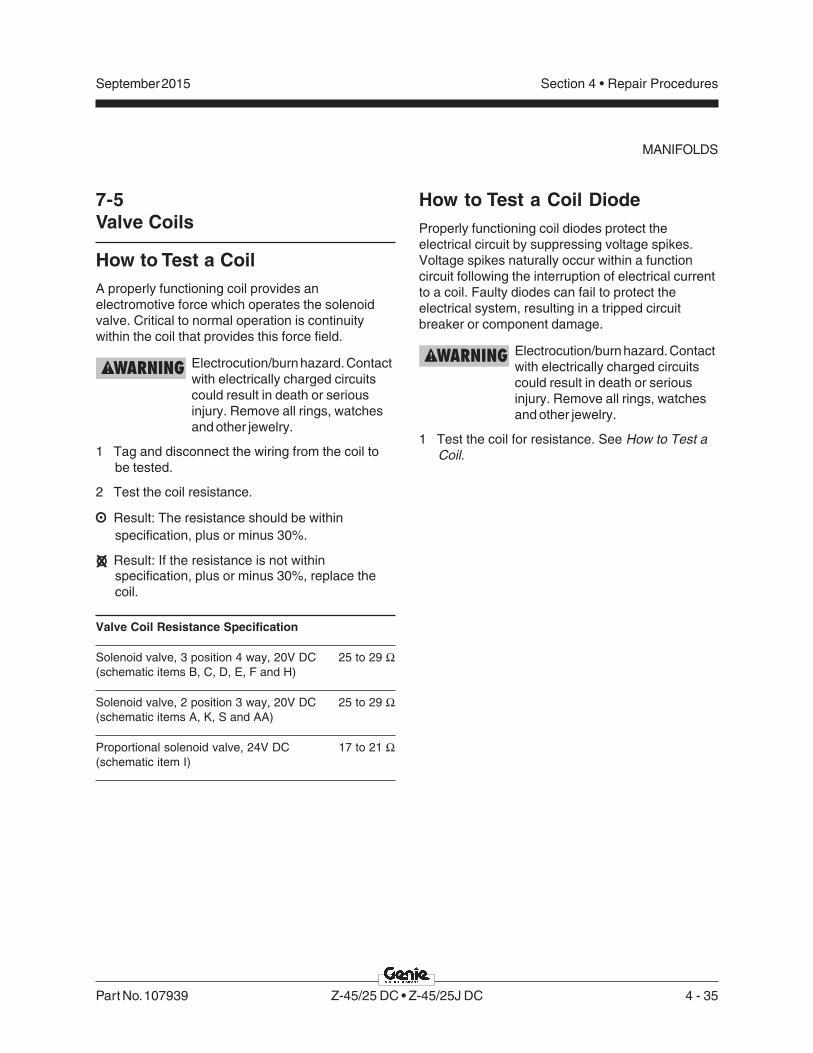
Part No. 107939 Z-45/25 DC • Z-45/25J DC 4 - 35
September 2015 Section 4 • Repair Procedures
7-5Valve Coils
How to Test a CoilA properly functioning coil provides anelectromotive force which operates the solenoidvalve. Critical to normal operation is continuitywithin the coil that provides this force field.
Electrocution/burn hazard. Contactwith electrically charged circuitscould result in death or seriousinjury. Remove all rings, watchesand other jewelry.
1 Tag and disconnect the wiring from the coil tobe tested.
2 Test the coil resistance.
Result: The resistance should be withinspecification, plus or minus 30%.
Result: If the resistance is not withinspecification, plus or minus 30%, replace thecoil.
Valve Coil Resistance Specification
Solenoid valve, 3 position 4 way, 20V DC 25 to 29 Ω(schematic items B, C, D, E, F and H)
Solenoid valve, 2 position 3 way, 20V DC 25 to 29 Ω(schematic items A, K, S and AA)
Proportional solenoid valve, 24V DC 17 to 21 Ω(schematic item I)
How to Test a Coil DiodeProperly functioning coil diodes protect theelectrical circuit by suppressing voltage spikes.Voltage spikes naturally occur within a functioncircuit following the interruption of electrical currentto a coil. Faulty diodes can fail to protect theelectrical system, resulting in a tripped circuitbreaker or component damage.
Electrocution/burn hazard. Contactwith electrically charged circuitscould result in death or seriousinjury. Remove all rings, watchesand other jewelry.
1 Test the coil for resistance. See How to Test aCoil.
MANIFOLDS

4 - 36 Z-45/25 DC • Z-45/25J DC Part No. 107939
September 2015Section 4 • Repair Procedures
2 Connect a 10Ω resistor to the negative terminalof a known good 9V DC battery. Connect theother end of the resistor to a terminal on thecoil.
Resistor, 10ΩΩΩΩΩGenie part number 27287
Note: The battery should read 9V DC or more whenmeasured across the terminals.
a multimeterb 9V DC batteryc 10Ω resistord coil
Note: Dotted lines in illustration indicate areversed connection as specified instep 6
3 Set a multimeter to read DC current.
Note: The multimeter, when set to read DC current,should be capable of reading up to 800 mA.
4 Connect the negative lead to the other terminalon the coil.
5 Momentarily connect the positive lead from themultimeter to the positive terminal on the 9V DCbattery. Note and record the current reading.
6 At the battery or coil terminals, reverse theconnections. Note and record the currentreading.
Result: Both current readings are greater than0 mA and are different by a minimum of 20%.The coil is good.
Result: If one or both of the current readings are0 mA, or if the two current readings do not differby a minimum of 20%, the coil and/or itsinternal diode are faulty and the coil should bereplaced.
9VBATTERY
10
RESISTOR
�
MULTIMETER
COIL
+
-
+
-
d
b
b
a
c
c
MANIFOLDS

Part No. 107939 Z-45/25 DC • Z-45/25J DC 4 - 37
September 2015 Section 4 • Repair Procedures
3 Remove the retaining fasteners from the centerturntable cover. Remove the cover from themachine.
4 Disconnect the battery backs from the machine.
Electrocution/burn hazard. Contactwith electrically charged circuitscould result in death or seriousinjury. Remove all rings, watchesand other jewelry.
5 Tag, disconnect and plug the hydraulic hosesfrom the turntable rotation motor manifold. Capthe fittings on the manifold.
Bodily injury hazard. Sprayinghydraulic oil can penetrate andburn skin. Loosen hydraulicconnections very slowly to allowthe oil pressure to dissipategradually. Do not allow oil to squirtor spray.
6 Attach a lifting strap from an overhead crane orother suitable lifting device to the turntablerotation assembly.
7 Remove the turntable rotation assemblymounting fasteners.
8 Carefully remove the turntable rotationassembly from the machine.
Crushing hazard. The machinecould tip over when the turntablerotation assembly is removed ifthe turntable rotation lock is not inthe locked position.
Crushing hazard. The turntablerotation assembly could becomeunbalanced and fall whenremoved from the machine if notproperly supported by theoverhead crane.
8-1Turntable Rotation Assembly
How to Remove the TurntableRotation AssemblyNote: When removing a hose assembly or fitting,the O-ring on the fitting and/or hose end must bereplaced and then torqued to specification duringinstallation. Refer to Section 2, Hydraulic Hose andFitting Torque Specifications.
Note: Perform this procedure with the machine on afirm, level surface.
1 Raise the secondary boom until the upper pivotis above the turntable covers. Turn the machineoff.
2 Secure the turntable from rotating with theturntable rotation lock pin.
Crushing hazard. The machinecould tip over when the turntablerotation assembly is removed ifthe turntable rotation lock is not inthe locked position.
Unlocked position
Locked position
Turntable Rotation Components

4 - 38 Z-45/25 DC • Z-45/25J DC Part No. 107939
September 2015Section 4 • Repair Procedures
Motor Controller
9-1Motor Controller
The drive motor controller is located under the non-steer end drive chassis cover. The drive motorcontroller can recognize machine drivemalfunctions and display controller fault codes byflashing a LED at the ground controls and on themotor controller. See the Fault Code section of thismanual for a list of fault codes and additionalinformation. There are no adjustments needed onthe drive joystick controller. For further informationor assistance, consult the Genie Industries ServiceDepartment.
How to Test the Motor ControllerNote: Use the following procedure to test the motorcontroller. If the motor controller is found to befaulty, note which test failed and which fault code(if any) was present at the time of failure.
1 Turn the key switch to the off position anddisconnect the battery packs from the machine.
2 Tag and disconnect all power cables from themotor controller.
Electrocution/burn hazard. Contactwith electrically charged circuitscould result in death or seriousinjury. Remove all rings, watchesand other jewelry.
3 Press the release tab on the motor controllerharness connector and remove the motorcontroller harness connector from the motorcontroller.
4 Set an ohmmeter to diode test mode.
5 Connect the leads from an ohmmeter to testeach motor controller terminal combinationlisted below and check the forward / reversebias (diode test).
Result: All desired results must be within thespecified range. If any test has a result notwithin the specified range, replace the motorcontroller.
Forward Bias:
Test Desired result
Positive Lead Negative Lead
M- B+ 0.4 to 0.45
B- M- 0.4 to 0.45
F1 B+ 0.45 to 0.5
F2 B+ 0.45 to 0.5
B- F1 0.45 to 0.5
B- F2 0.45 to 0.5
Reverse Bias:
Test Desired result
Positive Lead Negative Lead
B+ M- Rises to .0L V
M- B- Rises to .0L V
B+ F1 Rises to .0L V
B+ F2 Rises to .0L V
F1 B- Rises to .0L V
F2 B- Rises to .0L V

Part No. 107939 Z-45/25 DC • Z-45/25J DC 5 - 1
September 2015 Section 5 • Fault Codes
Before Troubleshooting:
Read, understand and obey the safety rules andoperating instructions in the appropriateOperator's Manual on your machine.
Be sure that all necessary tools and testequipment are available and ready for use.
Be aware of the following hazards and followgenerally accepted safe workshop practices.
Crushing hazard. When testingor replacing any hydrauliccomponent, always supportthe structure and secure itfrom movement.
Electrocution/burn hazard. Contactwith electrically charged circuitscould result in death or seriousinjury. Remove all rings, watchesand other jewelry.
Bodily injury hazard. Sprayinghydraulic oil can penetrate andburn skin. Loosen hydraulicconnections very slowly to allowthe oil pressure to dissipategradually. Do not allow oil tosquirt or spray.
Note: Two persons will be required to safelyperform some troubleshooting procedures.
Fault Codes
Observe and Obey:
Troubleshooting and repair procedures shall becompleted by a person trained and qualified onthe repair of this machine.
Immediately tag and remove from service adamaged or malfunctioning machine.
Repair any machine damage or malfunctionbefore operating the machine.
Unless otherwise specified, perform eachrepair procedure with the machine in thefollowing configuration:
• Machine parked on a firm, level surface
• Boom in stowed position
• Turntable rotated with the boom between the non-steer wheels
• Key switch in the off position with the key removed
• Wheels chocked
• All external AC power supply disconnectedfrom the machine

5 - 2 Z-45/25 DC • Z-45/25J DC Part No. 107939
September 2015Section 5 • Fault Codes
FAULT CODES
Tip-over hazard. When adjustingthe raised drive speed settings,the maximum raised drive speedmust not exceed specification.Refer to Section 2, Specifications.If the machine is allowed to drivefaster than specification, themachine could become unstableand will tip over.
Note: Additional troubleshooting of the fault codesmay be accomplished by using the hand-heldpendant motor controller programmer (Genie partnumber 56303-S).
Note: When using the hand-held pendant motorcontroller programmer, the M1 MAX SPEED needsto be set to 33. If needed, adjust the M1 MAXSPEED higher or lower to achieve the maximumraised drive speed. Refer to Section 2,Specifications.
The controller status indicator light will flash a faultcode to aid in troubleshooting. This indicator lightis mounted on the left side of the ground controlbox.
Fault codes are two digits. The controller statusindicator light will blink the first digit of a two digitcode, pause for 1 second, and then blink thesecond digit. There will be a 2 second pausebetween codes.
For example: the indicator light blinks 4consecutive times, pauses for 1 second, and thenblinks 1 time. That would indicate Fault Code 41.

Part No. 107939 Z-45/25 DC • Z-45/25J DC 5 - 3
September 2015 Section 5 • Fault Codes
Fault Code Chart
Continued on next page
Fault CodeProgrammer
Diagnostic DisplayCondition Possible Causes Solution
Controller status indicator light is OFF or is ON but not
blinking
COMMUNICATION ERROR
Machine will not drive.
The key switch or red Emergency Stop button(s) was cycled on and off faster than 5 seconds OR controller sensed an internal error during start up.
Push in the ground control red Emergency Stop button to the OFF position and wait for 5 seconds. Pull out the ground control red Emergency Stop button out to the ON position. If problem persists, replace the motor controller.
01 Normal operation.
12 HW FAILSAFE 1-2-3 Machine will not drive.The motor controller failed self test.
Replace the motor controller.
13 M- SHORTED Machine will not drive.
The motor controller has a internal short between M- and B- terminals.
Test the motor controller, see the Repair Section.
FIELD OPEN Machine will not drive.
Motor wiring is loose OR motor is defective OR motor controller has an internal short.
Check for loose or open connections at the drive motors and motor controller OR replace the defective drive motor OR test the motor controller. See the Repair Section.
ARM SENSOR Machine will not drive.Defective motor controller.
Replace the motor controller.
FLD SENSOR Machine will not drive.Defective motor controller.
Replace the motor controller.

5 - 4 Z-45/25 DC • Z-45/25J DC Part No. 107939
September 2015Section 5 • Fault Codes
FAULT CODE CHART
Fault CodeCode Scanner
DisplayCondition Possible Causes Solution
21 THROTTLE FAULT 1 Machine will not drive.
Open in wht/red wire #32 at pin 14 or red/wht wire #29 at pin 16 on the motor controller going from drive joystick to pins 14 and 16 at the motor controller OR pin 14 is internally shorted to power or ground OR the potentiometer on the drive joystick defective.
Consult Genie Industries Service Department.
THROTTLE FAULT 2 Machine will not drive.
Pin 14 (wht/red #32) is shorted to power or ground OR the potentiometer on the drive joystick is defective.
Consult Genie Industries Service Department.
31 CONT DRVR OC Machine will not drive.
Main contactor (PR1) coil defective OR brake release relay CR5 defective.
Replace main contactor PR1 or brake release relay CR5 OR replace the motor controller.
32 MAIN CONT WELDED Machine will not drive.
Main contactor (PR1) contacts stuck closed OR grn wire at pin 17 on motor controller shorted to ground OR open in motor armature wiring OR motor controller has a internal short to ground.
Consult Genie Industries Service Department.
33 PRECHARGE FAULT Machine will not drive.
External short between B+ terminal on motor controller and ground OR motor controller is defective.
Repair short between B+ terminal on motor controller and ground OR replace motor controller. Note: Short can be on any part of circuit connected to the B+ terminal on the motor controller.

Part No. 107939 Z-45/25 DC • Z-45/25J DC 5 - 5
September 2015 Section 5 • Fault Codes
FAULT CODE CHART
Fault CodeCode Scanner
DisplayCondition Possible Causes Solution
34 MISSING CONTACTOR Machine will not drive.
Motor controller does not detect the main contactor PR1 or brake release relay CR5.
Consult Genie Industries Service Department.
MAIN CONT DNC Machine will not drive.
Main contactor PR1 or brake release relay CR5 did not close OR open in org/red wire to PR1 and/or CR5 OR main contactor and/or brake release relay is defective.
Consult Genie Industries Service Department.
41 LOW BATTERY VOLTAGE
Machine will not drive.Battery supply voltage to motor controller less than 32V DC.
Completely charge batteries OR check battery cable condition OR check for corrosion or loose connections at battery terminals and motor controller.
42 OVERVOLTAGE Machine will not drive.
Battery supply voltage to motor controller more than 55V DC OR machine is being operated with the battery charger plugged in.
Be sure the battery charger is disconnected OR check for loose battery cables or poor connections
43 THERMAL CUTBACK Machine will not drive.
Machine being operated outside of temperature range of -13°F to 185°F / -25°C to 85°C OR machine being driven under excessive load OR motor controller is not being cooled sufficently.
Operate machine within specified temperature limits OR check for debris around motor controller preventing proper cooling of the controller OR check for mechanical restrictions causing excessive load on the machine.

5 - 6 Z-45/25 DC • Z-45/25J DC Part No. 107939
September 2015Section 5 • Fault Codes
This page intentionally left blank.

Part No. 107939 Z-45/25 DC • Z-45/25J DC 6 - 1
September 2015 Section 6 • Schematics
Schematics
Observe and Obey:
Troubleshooting and repair procedures shall becompleted by a person trained and qualified onthe repair of this machine.
Immediately tag and remove from service adamaged or malfunctioning machine.
Repair any machine damage or malfunctionbefore operating the machine.
Before Troubleshooting:
Read, understand and obey the safety rules andoperating instructions in the appropriateOperator's Manual on your machine.
Be sure that all necessary tools and testequipment are available and ready for use.
About This SectionThere are two groups of schematics in this section.
Electrical Schematics
Electrocution/burn hazard. Contactwith electrically charged circuitscould result in death or seriousinjury. Remove all rings, watchesand other jewelry.
Hydraulic Schematics
Bodily injury hazard. Sprayinghydraulic oil can penetrate andburn skin. Loosen hydraulicconnections very slowly to allowthe oil pressure to dissipategradually. Do not allow oil to squirtor spray.
General Repair Process
Malfunctiondiscovered
Identifysymptoms
Troubleshoot
Performrepair
Return toservice problem
solved
problemstill exists
Inspectand test

6 - 2 Z-45/25 DC • Z-45/25J DC Part No. 107939
September 2015Section 6 • Schematics
Electrical Symbols Legend
+
-
Battery
OR
G/B
LK-1
Wire colorwith cablenumber
15AMP.
Circuit breaker
Connectionno terminal
P1
Red EmergencyStop buttonnormally closed
KS1
GRND
PLAT
Key switch
PR4
Relay panelcontactor
Solenoid orrelay coil
Horn
Tilt sensor
NCLS2
Limit switchnormally closedheld open
NOLS1
Limit switchnormally openheld closed
HORN P4
Horn buttonnormally open
T-circuitsconnect
L1 FB
Light
TP29
Quick disconnectterminal
Diode
CR
4
Relay contactnormally open
TS3
PLAT.
DW
NP
LAT.U
P
Toggle switch SPDT
Circuits crossingno connection
TS6
RIG
HT
LEFT
Toggle switch DPDT
Limit switch
NO
LS3
NC
GR
N/B
LK
TB17
Groundsupressioncircuit
speed controllerBoom function
WH
T
GRNRED
BP1
BL
K/R
EDTB20
Terminal
BLK #21TB21
T-circuits connectat terminal

Part No. 107939 Z-45/25 DC • Z-45/25J DC 6 - 3
September 2015 Section 6 • Schematics
Hydraulic Symbols Legend
M
Pressure gauge
Filter
Fixed displacement pump
Bi-directional motor
Pump prime mover (motor)
Cylinder
Orifice with size
0.035”
Variable orificeor shut-off valve
Check valve
2 position 2 waysolenoid valve
Solenoid operatedproportional valve
(before serial number 22566)
Solenoid operated 2 pos.,3 way, directional valve
3 position 4 way directionalsolenoid valve
Shuttle valve
Counterbalance valve
Priority flow regulator
Differential sensing valve
Relief valve
Spring applied,hydraulically releasedbrake
Pressure switch
COM
N.O.
N.C.
Solenoid operatedproportional valve
(after serial number 22565)
Check valve, pilot operated

6 - 4 Z-45/25 DC • Z-45/25J DC Part No. 107939
September 2015Section 6 • Schematics

Section 6 • Schematics September 2015
6 - 5
Electrical Schematic, Z-45/25 and Z-45/25J,ANSI • CSA • AS (before serial number 31015)
6 - 6

Section 6 • Schematics September 2015
1
2
3
4
5
6
7
8
A B C D E F G H I J K L M N
6 - 6 Z-45/25 DC • Z-45/25J DC Part No. 107939
Electrical Schematic, Z-45/25 and Z-45/25J,ANSI • CSA • AS (before serial number 31015)
P2
2L
SB
K
L48
C1
33
PL
AB
L/R
DC
2P
-1C
2B
-1
C32
U6ACURTIS 1244
SEPEX CONTROLLER
F4500A
1
2
C3
B-9
C1
B-1
2
D2
H2
GR/BK
WH
TB134
C1P-12C132PLI BL/WH
C7
B-1
LS18
C7
B-2
C7
P-2
P2
3B
AT
WH
1 3
4
6 7
5
12 8
OROR
C6
B-4
0O
R
C6
B-2
4
C4
0L
SO
RC
2P
-2C
2B
-2
TB40
C29JSH RD/WH
C32JSL WH/RD
C30FWD WH
C31REV WH/BK
BK
2G
AC
HA
SS
ISG
RO
UN
D
BK
-6
WH
-7
BK
-5
RD
-5
WH
-4
WH
-5
BK
-5
RD
RD
/BK
BK P26BAT
WH
-6
13LS1
(EXT)14
1
P2
2B
AT
C7P-1
HO
RN
C8
-BC
8-A
C8
-C
P42BAT OR/RD C6B-3
C6
B-2
5C
FIL
BK
C6B-22
C12DRE BL/WH
C6
B-1
2
BK
C6
B-2
0R
D
C11
-3
C11
-4
C11
-1
C11
-2C
10
-2
C1
0-1
C1
0-4
C1
0-3
BK
BK
BK
-7
C6
B-3
4
C6
B-9
BK
/RD
C6
B-2
8
C6
B-2
9
C6
B-3
2
C6
B-3
1
C6
B-3
0
C7
B-4
P2
0B
AT
RD
C2
B-4
C3
B-3
C1
B-2
C2
B-5
C1
B-3
C1
B-4
C1
B-5
C1
B-6
C9P-2
C9P-3
R4
2B
AT
OR
/RD
C2
P-4
C3
BA
TR
D/W
HC
3P
-3
C2
8T
TA
RD
/BK
C1
P-2
C1
34
PW
RG
RC
2P
-5
C9
HR
NB
K/R
DC
3P
-9
C2
9JS
HR
D/W
HC
1P
-3
C3
2JS
LW
H/R
DC
1P
-6
C3
1R
EV
WH
/BK
C1
P-5
CR5
PR3
PR2
PR3
PR2
BK
P42BAT OR/RD
R42BAT OR/RD
P24BAT WH
RD
C12DRE BL/WH
BK
(GND)
TILTALARM
RD
WH-(FS)
FS1
H1
RD-(FS)
PLATFORM
GROUND
P1 KS1 TB22
P3HORN
P2
RD
C9P-1 BK
+
RD
P20BAT RD
BK-(FS)
OR
/RD
CR1
CR2
TB42
RD
/WH
30
8785
86
30
87
86
85
BR
N
BR
N
HM
CO
IL-P
R1
OF
F-L
MT
SP
DIN
P
INT
ER
LO
CK
53 17
GR
BK
/RD
BK
-4
LS4(SEC)
BL
/WH
OR
/RD
LS2(PRI)
TB23
RD
/BK
OR
/RD
C6
B-3
9C
R5
RD
/BK
OR
/RD
20
CR
5
_
+
22
21
22
21
86
85
CB1
10 A
C1
P-4
RD
20
AP2
24V
FO
RW
AR
D
PO
T.
LO
W
DIO
DE
RE
TU
RN
+4
8V
INP
UT
PO
T.H
I
RE
VE
RS
E
101 9 11 1614
PR1
AP248V
OR
/RD
WH
WH
/BK
WH
/RD
RD
/WH
F1200A
F510A
F2200A
+
++
+
LEFTBOX
_
__
_
+48 V
C3
0F
WD
WH
2
CR
14
8V
DC
PO
WE
RR
EL
AY
FL
AS
HIN
GB
EA
CO
N(O
PT
ION
)
CR
24
8V
DC
PO
WE
RR
EL
AY
FB
+
HO
UR
ME
TE
R
HO
RN
RE
LA
Y
BA
SE
CO
NT
RO
LB
OX
GR
OU
ND
CR4
TIL
TS
EN
SO
R
RD
WH
BK
BR
N
F1
+
86
85
30
87
RIGHTMOTOR
BR
N
CR
5B
RA
KE
RE
LE
AS
EC
OIL
PR
1S
EP
EX
CO
NT
RO
LL
ER
CO
NTA
CT
OR
CO
IL
AP1
AU
XIL
IAR
YL
IFT
PU
MP
PR
IMA
RY
LIF
TP
UM
P
PR3 PR2
WH
BK
AC POWER
F2 F1
A2
A1
A2
A1+
_
PUMPPUMP
+
++
+
CH
AR
GE
R
LEFTMOTOR
RIGHTBOX
_
__
_
GR
OU
ND
+24V
SWITCH SHOWN WITH BOOM EXTENDED.NOTES:1. ALL LIMIT SWITCHES SHOWN WITH BOOM IN STOWED POSITION EXCEPT AS NOTED.2. ALL SOLENOID AND RELAY COILS ARE 24VDC EXCEPT WHERE NOTED.
SWITCH SHOWN WITH BOOM ROTATED PAST EITHER NON-STEER WHEEL.
F2
F2F1 B+M-AP1 B-
L37
WH
ES0273G (NON-JIB MODELS)ES0274G (JIB MODELS)
D79

Section 6 • SchematicsSeptember 2015
1
2
3
4
5
6
7
8
N M L K J I H G F E D C B A
Part No. 107939 Z-45/25 DC • Z-45/25J DC 6 - 7
Electrical Schematic , Z-45/25 and Z-45/25J,ANSI • CSA • AS (before serial number 31015)
C6
B-4
WH
BK
(GND)
TU
RN
TA
BL
ER
OTA
TE
LE
FT
SE
CO
ND
AR
YB
OO
MU
P
SE
CO
ND
AR
YB
OO
MD
OW
N
DE
SC
EN
TA
LA
RM
(OP
TIO
N)
C12DRE BL/WH
RD
TS55 FUNCTIONENABLE
TB5 TB11 TB10TB4
TURNTABLEROTATE
RD
TS62 TS60
SECONDARYBOOM
C32JSL WH/RD
C31REV WH/BK
C29JSH RD/WH
TS12
TURNTABLEROTATE
SECONDARYBOOMTS10 TS11
PRIMARYBOOM
C30FWD WH
RD
/WH
RD
PR
IMA
RY
BO
OM
DO
WN
PL
AT
FO
RM
LE
VE
LU
P
PR
IMA
RY
BO
OM
EX
TE
ND
PR
IMA
RY
BO
OM
RE
TR
AC
T
PR
IMA
RY
BO
OM
UP
PL
AT
FO
RM
LE
VE
LD
OW
N
PR
OP
OR
TIO
NA
LF
LO
WC
ON
TR
OL
PR
2P
RIM
AR
YP
UM
PC
ON
TA
CT
OR
CO
IL
GR
/WH
PS
1B
RA
KE
PR
ES
SU
RE
SW
ITC
H
ST
EE
RL
EF
T
PR
3A
UX
ILIA
RY
PU
MP
CO
NTA
CT
OR
RE
LA
Y
ST
EE
RR
IGH
T
CR
3A
UX
ILIA
RY
PU
MP
CO
NTA
CT
OR
CO
IL
C6
B-2
7
CR3
N.C
.B
RA
KE
RE
LE
AS
EV
ALV
E
TR
AV
EL
AL
AR
M
LS3
BR
N-8
RD
-8
JIB MANIFOLD
RE
TR
AC
T
TB7TB2 TB1 TB8 TB15 TB14
TS61
PRIMARYBOOM
TS63
PRIMARYBOOM
TS59
PLATFORMLEVEL
TB18
TB6
GR/WH
TB17
TB19
TS57
PLATFORMROTATE
TS58
JIBBOOM
TS7TS9
PRIMARYBOOMTS13
PLATFORMLEVEL
PLATFORMROTATE
BRN
RD
BK/RD
ROTARYOEMFLOWCONTROL
BP1
TB27
GR/WH
TB36
TB37
PS
1
RD
AUXILIARYPUMP
TS51
WH
-8
OR
/RD
BK
-8
TB12
F
E
AUXILIARYPUMP
2
3
4
5
1
DP1
RL
7
8
9
10
6
BR
N
RD/BK-R6
ENABLEDRIVE
CR6
CR5
L1DRIVEENABLELED
STEER
DRIVE
LIFT
RD
-AU
X
CR7
DR
IVE
EN
AB
LE
LIM
ITS
WIT
CH
2
13
14
22
21
+
TS8
JIBBOOM
PL
AT
FO
RM
RO
TA
TE
LE
FT
(JIB
UP
-O
PT
ION
)
RIG
HT
LE
FT
DO
WN
UP
UP
DO
WN
EX
TE
ND
UP
DO
WN
LE
FT
UP
RIG
HT
DO
WN
DO
WN
UP
PL
AT
FO
RM
RO
TA
TE
RIG
HT
(JIB
DO
WN
-O
PT.)
UP
DO
WN
EX
TE
ND
RE
TR
AC
T
UP
DO
WN
UP
DO
WN
RIG
HT
LE
FT
LE
FT
RIG
HT
H3
+
TU
RN
TA
BL
ER
OTA
TE
RIG
HT
+
H4
30
87a
86
85
30
87
86
8587
30
86
85
30
87a 87
OR/BK-R6R
DREV
FWD
20K
CR19A
BRN
BK
WH
OR
/RD
CR19B
CR19A30
87
30
87 CR19B
BCIOPTION
P42BAT OR/RD
85
86 30
87
CR20
PR2
CR
20
PR
IMA
RY
PU
MP
CO
NTA
CT
OR
RE
LA
Y
BK
OR/RD
PR2
PR3
PR3
CR5CR5
TB44
C3
P-4
C4
TR
LW
H
C3
P-5
C4
TR
RW
H/B
K
C3
P-1
1C
11
SB
DB
L/B
K
C3
P-1
0C
10
SB
UB
L
C3
P-2
C2
PB
DR
D/B
K
C3
P-1
C1
PB
UR
D
C3
P-8
C8
PB
RB
K/W
H
C3
P-7
C7
PB
EB
K
C4
P-2
C1
4P
LU
OR
C4
P-3
C1
5P
LD
OR
/BK
C4
5JS
VG
R/W
H
C3
7S
TC
BL
/BK
C3
6S
TC
CB
L
R4
1D
RE
OR
/BK
C4
P-4
C1
6D
RE
OR
/RD
C3
P-1
2C
12
DR
EB
L/W
H
C4
P-1
C1
3D
RE
LB
L/R
D
C1
P-1
0
C1
P-1
1
C2
P-3
C1
P-1
C2
7A
UX
RD
C1
9L
PM
PG
R/W
H
C6
LF
CW
H/R
D
C2
P-7
C3
P-6
C4
P-7
C2
P-6
C4
4JD
AG
R/B
K
C4
P-6
C1
8P
RR
GR
/BK
C4
P-5
C1
7P
RL
GR
C3
B-4
C3
B-5
C3
B-1
0
C3
B-1
1
C3
B-2
C3
B-1
C3
B-7
C3
B-8
C4
B-2
C4
B-3
C6
B-5
WH
/BK
C6
B-1
0B
L
C6
B-1
1B
L/B
K
C6
B-1
RD
C6
B-2
RD
/BK
C6
B-7
BK
C6
B-8
BK
/WH
C6
B-1
4O
R
C6
B-1
5O
R/B
K
C6
B-1
8G
R/B
K
C6
B-1
7G
R
C4
B-5
GR
C4
B-6
GR
/BK
C2
B-6
C3
B-6
WH
/RD
C4
B-7
GR
/WH
C6
B-6
WH
/RD
C6
B-3
7B
L/B
K
C6
B-3
6B
L
C6
B-3
5
RD
/WH
C4
B-4
C3
B-1
2
C4
B-1
C2
B-3
C1
B-1
1
C1
B-1
0
C1
B-1
C6B-38 GR/WH
C2
B-7
C6
B-2
6C
12
DR
EB
L/W
H
C44DA BK
RD
GR
/WH
C6
B-1
9
C6
B-1
6C
16
DR
E
C6
B-1
3C
13
DR
EL
BL
/RD
C6
B-2
1D
RE
GN
DB
RN
C7
B-3
BA
TG
ND
BR
NC
7P
-3B
AT
GN
DB
RN
GR/WH
C1
3-1
C1
2-1
C1
3-2
C1
2-2
C1
6-1
C1
7-1
C1
8-2
C1
6-2
C2
0-1
C2
1-1
C2
1-2
C2
0-2
C2
3-1
C2
2-1
C2
2-2
C2
3-2
C1
8-1
C1
9-1
C1
9-2
C1
8-2
C1
5-1
C1
4-1
C1
4-2
C1
5-2
C2
4-1
C2
5-1
C2
4-2
C2
5-2
C2
6-1
C2
6-2
C31REV WH/BK
C30FWD WH
C32JSL WH/RD
C29JSH RD/WH
P24BAT WHP24BAT WH
R42BAT OR/RD
BR
N
RD
/WH
OR
/RD
WH
WH
BK
TS1BCI
4 5 3
OR
/BK
OR
/RD
OR
8 7 6 5 4 3 2 1
86
85
85
86
RESET
SET TO “B”
DISCHARGE
SET TO “N”
L.V.I.
LVI/BCI OPTION
TS15
C4
4D
AB
K
C6
B-3
3C
44
DA
BK
33�
33�
D81 D82
D27
D69
D71
D73
D78
D85
D60
D59
D76
D4
D28
D74
D72
D80
D82
D50
D30
D29

September 2015 Section 6 • Schematics
6 - 86 - 7
Electrical Schematic , Z-45/25 and Z-45/25J,ANSI • CSA • AS (before serial number 31015)

Section 6 • Schematics September 2015
6 - 9 6 - 10
Ground Control Box Terminal Strip Wiring Diagram,Z-45/25 and Z-45/25J, ANSI • CSA • AS(before serial number 31015)

Section 6 • Schematics September 2015
1
2
3
4
5
6
7
8
A B C D E F G H I J K L M N
6 - 10 Z-45/25 DC • Z-45/25J DC Part No. 107939
Ground Control Box Terminal Strip Wiring Diagram, Z-45/25 and Z-45/25J,ANSI • CSA • AS (before serial number 31015)
DC
PR
IMA
RY
BO
OM
UP
1 2 4 5 6 7 8 10
PR
IMA
RY
BO
OM
DO
WN
TU
RN
TA
BL
ER
OTA
TE
LE
FT
TU
RN
TA
BL
ER
OTA
TE
RIG
HT
LIF
TF
LO
WC
ON
TR
OL
PR
IMA
RY
BO
OM
EX
TE
ND
PR
IMA
RY
BO
OM
RE
TR
AC
T
SE
CO
ND
AR
YB
OO
MU
P
LIF
TP
UM
P
LIF
TP
UM
P
PL
AT
FO
RM
LE
VE
LD
OW
N
PL
AT
FO
RM
LE
VE
LU
P
FO
OT
SW
ITC
HP
OW
ER
#2
SE
CO
ND
AR
YB
OO
MD
OW
N
19
1911
15
17
18
14
12
AU
XIL
IAR
YP
UM
PS
EL
EC
T
KE
YS
WIT
CH
PO
WE
R
+2
4V
DC
TO
PL
AT
FO
RM
27
22
23
ST
EE
RR
IGH
T
ST
EE
RL
EF
T
34
36
37
35
33
OF
F-L
IMIT
SP
EE
D4
0
BA
C3
B-1
C1
PB
UR
DR
D-T
S6
1
RD
/BK
-TS
61
WH
-TS
62
WH
/BK
-TS
62
BK
-TS
63
BK
/WH
-TS
63
BL
-TS
60
BL
/BK
-TS
60
C1
2D
RE
BL
/WH
OR
-TS
59
WH
-HM
OR
/BK
-TS
59
GR
-TS
57
GR
/BK
-TS
57
GR
/WH
GR
/WH
-J1
9
WH
-KS
1(D
2)
RD
-CR
3
GR
/WH
-J1
9
GR
/WH
-J1
9
OR
/RD
-LE
D
OR
/RD
-CR
1
GR
/WH
RD
-TS
51
GR
/WH
-TS
60
L3
7
TE
RM
INA
LB
AS
E(T
B)
1 2 4 5 6 7 8 10
19
1911
15
17
18
14
12
27
22
23
34
36
37
35
33
42
40
GR
OU
ND
CO
NT
RO
LH
AR
NE
SS
TO
SW
ITC
HP
AN
EL
GR
/BK
-TS
58
OR
/RD
CR
4
RD
/WH
OR
/RD
CR
1C
R2
87
A
30
86
85
BR
N
87
BK
87
87
A8
58
6
30
BR
N
CR
20
OR
/RD
BR
N
87
A8
6
30 8
5
87
BRN
OR
/RD
RD/BK
OR/BK
RD/WH
OR/RD
87
87
A8
5
30
86
GR/WH
CR
3
BR
N
87
A8
6
30 8
5
RD
87
GR
/WH
BRN
CR
5
GR
/WH
87
A8
6
30 8
5
87
C9
HR
NB
K/R
D
C6
B-9
R9
HR
N
C6
B-3
9C
R5
RD
/BK
C2
B-3
C4
1D
RE
OR
/BK
C6
B-3
5R
48
BR
KR
D/W
H
C3
B-3
C3
BA
TR
D/W
H
C6
B-3
P4
2B
AT
OR
/RD
C6
B-2
7R
27
AU
X
C6
B-1
9R
19
LP
EG
R/W
H
C3
B-2
C2
PB
DR
D/B
K
C3
B-4
C4
TR
LW
H
C3
B-5
C5
TR
RW
H/B
K
C3
B-6
C6
LF
CW
H/R
D
C3
B-7
C7
PB
EB
K
C3
B-8
C8
PB
RB
K/W
H
C3
B-1
0C
10
SB
UB
L
C3
B-1
1C
11
SB
DB
L/B
K
C3
B-1
2C
12
DR
EB
L/W
H
C4
B-2
C1
4P
LU
OR
C4
B-3
C1
5P
LD
OR
/BK
C4
B-5
C1
7P
RL
GR
C4
B-6
C1
8P
RR
GR
/BK
C4
B-7
C1
9L
PE
GR
/WH
C1
B-1
C2
7A
UX
RD
C1
B-1
1C
37
ST
CB
L/B
K
C1
B-1
0C
36
ST
CC
BL
C2
B-4
R4
2B
AT
OR
/RD
C2
B-6
C4
4JD
AG
R/B
K
C6
B-1
C1
PB
UR
D
C6
B-2
C2
PB
DR
D/B
K
C6
B-4
C4
TR
LW
H
C6
B-5
C5
TR
RW
H/B
K
C6
B-6
C6
LF
CW
H/R
D
C6
B-7
C7
PB
EB
K
C6
B-8
C8
PB
RB
K/W
H
C6
B-1
0C
10
SB
UB
L
C6
B-1
1C
11
SB
DB
L/B
K
C6
B-1
4C
14
PL
UO
R
C6
B-1
5C
15
PL
DO
R/B
K
C6
B-1
7C
17
PR
LG
R
C6
B-1
8C
18
PR
RG
R/B
K
C6
B-3
8C
19
LP
EG
R/W
H
C6
B-2
0P
22
LS
BK
C6
B-3
6C
36
ST
CC
BL
C6
B-3
7C
37
ST
CB
L/B
K
C6
B-2
2R
42
BA
TO
R/R
D
BK
-CR
4
C28TTA RD/BK
C29JSH RD/WH
C30FWD WH
C31REV WH/BK
C32JSL WH/RD
C16DRE OR/RD
C13DREL BL/RD C4B-1
C4B-4
C6
B-2
5
C1B-2
C1B-3
C1B-4
C1B-5
C1B-6
C6
B-2
6C
12
DR
EB
L/W
H
C3
B-9
C6B-13
C6B-16
C6B-28
C6B-29
C6B-30
C6B-31
C6B-32
P2
0B
AT
RD
C7
B-2
P2
3B
AT
WH
GR
OU
ND
ST
UD
C7B-3 BATGND BRN
BR
N
P20BAT RD C7B-4
BK
OR
/RD
OR
/RD
GR
/WH
-CR
3
C6
B-1
2C
12
DR
EB
L/W
H
OR
/RD
-42
A
C6
B-3
3C
44
DA
BK
PL
AT.
RO
TA
TE
RIG
HT
-(JIB
DO
WN
-OP
T)
PL
AT.
RO
TA
TE
LE
FT
-(JIB
UP
-OP
T)
D5
0B
KA
LA
RM
D3
0B
K-A
LA
RM
D2
9B
K-A
LA
RM
BK-ALARM
(JIB
-O
PT
ION
)D
ES
CE
NT
AL
AR
M4
44
4
C2
B-2
C4
0L
SO
R
SW
ITC
H4
8V
OLT
S4
2
C6
B-2
4C
40
LS
OR
C6
B-4
0C
40
LS
OR
BR
N
BK/RD
RD
GR/WH
RD/WH
C6B-21
BR
N
GR
/WH
C2
B-7
C4
5JS
VG
R/W
H
BR
N-H
M
BK
BRN
BK
-KS
1
BRN GND
GR/BK H6
RD TS55
RD TS51
BK C7-1
BK 22D
BL/WH C1-12
RD H6
C3
2
13
45
67
81
2
C2
3-4
P2
2B
AT
BK
KE
YS
WE
ITC
HP
OW
ER
13
41
34
RD
KS
1
RD
H6
C6
B-3
4C
13
4P
WR
RD
C2
B-5
P1
34
BA
TR
D
ES0273G (NON-JIB MODELS)ES0274G (JIB MODELS)
C7
C6
C4
BB
RO
WN
C3
BG
RE
EN
C2
BB
LA
CK
C1
BG
RA
Y
D7
2
D7
4
D6
0
D5
9
D7
8
D7
6
D8
5

Section 6 • SchematicsSeptember 2015
1
2
3
4
5
6
7
8
N M L K J I H G F E D C B A
Part No. 107939 Z-45/25 DC • Z-45/25J DC 6 - 11
Ground Control Box Switch Panel Wiring Diagram, Z-45/25 and Z-45/25J,ANSI • CSA • AS (before serial number 31015)
TS
57
TS
59
TS
58
TS
51
TS
60
TS
61
TS
63
TS
62
P1
CB
1
RD
C45JSV GR/WH (C2B-7)
BK
RD
BK
BK
GR
GR
/BK
WH-4A
WH/BK-5A
RD
BK
BK/WH-8A
BK-7A
RD
RD-27A
RD-1A
RD/BK-2A
RD
BK
BK
RD
GR/BK
GR
GR
BK
P20BAT RD (C7B-4)
RD
BK
BL-10A
BL/BK-11A
GR/WH-19A BK
RD
RD
RD
RD
RD
RD
WH
-HM
BK
BA
SE
BO
XH
AR
NE
SS
GR/BK-18A
RD
RD
GR/BK-44A
1
2
NC
GR-17A
RD
RD
WH
BRN
RD
RD
OR/BK-15A
OR-14A
OR/BK
OR
TS
55
BR
N-H
M
KS
1
RD C23-6
BK-22A
RD C23-7
RD
D2
RD 134A
WH
WH 23A
CB1
CR1
CR2
CR3
CR4
CR5
CR20
G6
KS1
10A CIRCUIT BREAKER
POWER RELAY, 48V
POWER RELAY, 48V
AUXILIARY PUMP RELAY
HORN RELAY
BRAKE RELEASE RELAY
PRIMARY LIFT PUMP RELAY
HOUR METER
KEY SWITCH
COMPONENT INDEX
L37
P1
TS51
TS55
TS57
TS58
TS59
TS60
LED, DRIVE CONTROLLER FAULT STATUS
EMERGENCY STOP BUTTON
AUXILIARY PUMP TOGGLE SWITCH
FUNCTION ENABLE TOGGLE SWITCH
PLATFORM ROTATE TOGGLE SWITCH
JIB UP / DOWN TOGGLE SWITCH (OPTION)
PLATFORM LEVEL UP / DOWN TOGGLE SWITCH
SECONDARY BOOM UP / DOWN TOGGLE SWITCH
TS61
TS62
TS63
PRIMARY BOOM UP / DOWN TOGGLE SWITCH
TURNTABLE ROTATE TOGGLE SWITCH
PRIMARY BOOM EXTEND / RETRACT TOGGLE SWITCH
D4
D80
D82
D28
G6
NOTE: DASHED LINES INDICATE OPTIONS.
ES0273G (NON-JIB MODELS)ES0274G (JIB MODELS)

September 2015 Section 6 • Schematics
6 - 126 - 11
Ground Control Box Switch Panel Wiring Diagram,Z-45/25 and Z-45/25J, ANSI • CSA • AS
(before serial number 31015)

Section 6 • SchematicsSeptember 2015
1
2
3
4
5
6
7
8
N M L K J I H G F E D C B A
Part No. 107939 Z-45/25 DC • Z-45/25J DC 6 - 13
Platform Control Box Wiring Diagram, Z-45/25 and Z-45/25J,ANSI • CSA • AS (before serial number 31015)
OR
/BK
OR
/BK
-R6
GR
/WH
-R7
RD
-J7
GR
/WH
-45
GR
/WH
C2
7A
UX
RD
C2
9JS
HR
D/W
H
C3
0F
WD
WH
C3
1R
EV
WH
/BK
C3
2JS
LW
H/R
D
C3
6S
TC
CB
L
C3
7S
TC
BL
/BK
R4
1D
RE
OR
/BK
C4
4JD
AG
R/B
K
C4
5JS
VG
R/W
H
C1
PB
UR
D
C2
PB
DR
D/B
K
C3
BA
TR
D/W
H
C4
TR
LW
H
C5
TR
RW
H/B
K
C6
LF
CW
H/R
D
C7
PB
EB
K
C8
PB
RB
K/W
H
C9
HR
NB
K/R
D
C11
SB
DB
L/B
K
C1
0S
BU
BL
C1
2D
RE
BL
/WH
C1
3D
RE
LB
L/R
D
C1
4P
LU
OR
C1
5P
LD
OR
/BK
C1
6D
RE
OR
/RD
C1
7P
RL
GR
C1
8P
RR
GR
/BK
C1
9L
PM
PG
R/W
H
P2
6B
AT
BK
P2
5B
AT
RD
P2
4B
AT
WH
BK
-JIB
GN
D
GR
/WH
-45
GR
/WH
-45
BRN-J1
BRN-BATGND
BRN-JIBGND
C2
8T
TA
RD
/BK
C1
P-1
C1
P-3
C1
P-4
C1
P-5
C1
P-2
C1
P-6
C1
P-1
0
C1
P-1
1
C2
P-3
C2
P-6
C2
P-7
C3
P-1
C3
P-2
C3
P-3
C3
P-4
C3
P-5
C3
P-6
C3
P-7
C3
P-8
C3
P-9
C3
P-1
0
C3
P-1
1
C3
P-1
2
C4
P-1
C4
P-2
C4
P-3
C4
P-4
C4
P-5
C4
P-6
C4
P-7
C9
P-1
C9
P-2
C9
P-3
R4
2B
AT
OR
/RD
C2
P-4
C1
P(G
Y)
C2
P(B
K)
C4
P(B
R)
C3
P(G
R)
BK
WH
C1
34
PW
RR
D
BR
N-B
AT
GN
D
P2
2B
AT
BK
P2
3S
WB
AT
WH
C7
P-1
C7
P-2
C7
P-3
OR
/RD
RD
/BK
-R6
BRN-RELAY
C9
HR
NB
K/R
D
RD
-HR
N
C2
7A
UX
RD
RD
-AU
X
RD
-DR
E
BK
/WH
-DR
E
C1
3D
RE
LB
L/R
D
C4
4JD
AG
R/B
K
C1
8P
RR
GR
/BK
C1
7P
RL
GR
C1
5P
LD
OR
/BK
C1
4P
LU
OR
C32JSL WH/RD
C29JSH RD/WH
C30FWD WH
C31REV WH/BK
OR/BK-R6
RD-DRE
C12DRE BL/WH
RD-J7
RD-SW
RD/BK-R6
BK/WH-DRE
C37STC BL/BK
C36STCC BL
P2
3S
WB
AT
WH
C7
P-2
C3
BA
TR
D/W
HC
3-3
P2
2B
AT
BK
C7
P-1
P2
6F
SB
KC
9P
-1
C5
TR
RW
H/B
K
C4
TR
LW
H
C1
0S
BU
BL
C2
PB
DR
D/B
K
C8
PB
RB
K/W
H
C7
PB
EB
K
RD
-SW
C1
9L
PM
PG
R/W
H
C6
LF
CW
H/R
D
TS12 TS10
TS11
TS13
TS8
TS7
TS9
TS1
P3RD
BR
N-B
CI
GR-LFC
RD-RPM
RD
/BK
H1
GR
/WH
-45
L1
1
2
3
4
5
6
7
8
9
10
FWD
REV
20k
LIFT
DRIVE
RIGHT
LEFT
DP1
34
NO
BR
N-J
1
C1
PB
UR
D
C11
SB
DB
L/B
K
P2
RD
-HR
N
P24BAT WH
GR
/WH
-R
7
R4
2B
AT
OR
/RD
BR
N-B
CI
A1
BP1
DP1
P2
P3
TS1
TILT ALARM
ROTARY FLOW CONTROL DIAL
JOYSTICK - DRIVE / STEER
EMERGENCY STOP BUTTON
HORN BUTTON
AUXILIARY PUMP TOGGLE SWITCH
COMPONENT INDEX
TS7
TS8
TS9
TS10
TS11
TS12
TS13
TS15
PLATFORM ROTATE TOGGLE SWITCH
JIB BOOM UP / DOWN TOGGLE SWITCH (OPTION)
PLATFORM LEVEL TOGGLE SWITCH
SECONDARY BOOM TOGGLE SWITCH
PRIMARY BOOM UP / DOWN TOGGLE SWITCH
TURNTABLE ROTATE TOGGLE SWITCH
PRIMARY BOOM EXTEND / RETRACT TOGGLE SWITCH
DRIVE ENABLE TOGGLE SWITCH
1 1 1
NOTES:DASHED LINES INDICATE OPTIONS.
CR7CR6
RD
/BK
L4
8
D40
A1
C2
P-5
L48
12
NC
12 NC
1
2
NC
P3
H1 TITL ALARM
TS15
- +CR6 RELAY - DRIVE ENABLE
CR7 RELAY - JIB (OPTION)
BCI BATTERY CHARGE INDICATOR (OPTION)
18/19 CONTROL CABLE
C7P C9P
12V DCBATTERY
FOOTSWITCH
JIB(OPT.)
OPTION OPTION
L1 LED - DRIVE ENABLE
L48 LED - TILT ALARM
GR
OR
WH
BK
RD
WH/GR
YL
PRPL
BL
WH/YL
WH/RD
BP1GR
RD
BK/RD
BCI
D2
7
D82
D81
D69D
71
D73
ES0273G (NON-JIB MODELS)ES0274G (JIB MODELS)

September 2015 Section 6 • Schematics
6 - 14
Platform Control Box Wiring Diagram, Z-45/25 and Z-45/25J,ANSI • CSA • AS (before serial number 31015)
6 - 13

Section 6 • Schematics September 2015
6 - 15 6 - 16
Electrical Schematic , Z-45/25 and Z-45/25J, CE(before serial number 31015)

Section 6 • Schematics September 2015
1
2
3
4
5
6
7
8
A B C D E F G H I J K L M N
6 - 16 Z-45/25 DC • Z-45/25J DC Part No. 107939
Electrical Schematic , Z-45/25 and Z-45/25J, CE(before serial number 31015)
NOTES:1. ALL LIMIT SWITCHES SHOWN WITH BOOM IN STOWED POSITION EXCEPT AS NOTED.2. ALL SOLENOID AND RELAY COILS ARE 24VDC EXCEPT WHERE NOTED.
SWITCH SHOWN WITH BOOM EXTENDED.
ADD D40 ONLY IF UNIT HAS L4 AND L48.
1
B-AP1 M- B+F1 F2
F2
+24V DC
GR
OU
ND
RIGHTBOX
LEFTMOTOR
CH
AR
GE
R
PUMP PUMP
-
+A1
A2
A1
A2
F1F2
AC POWER
BK
WH
48
VD
CC
HA
RG
ER
PR2PR3
PR
IMA
RY
LIF
TP
UM
P
AU
XIL
IAR
YL
IFT
PU
MP
AP1
PR
1S
EP
EX
CO
NT
RO
LL
ER
CO
NTA
CT
OR
CO
IL
CR
5B
RA
KE
RE
LE
AS
EC
OIL
BR
N
RIGHTMOTOR
87
30
85
86
+
F1
BR
NB
K
WH
RD
TIL
TS
EN
SO
R
CR4
BA
SE
CO
NT
RO
LB
OX
GR
OU
ND
HO
RN
RE
LA
Y
HO
UR
ME
TE
R
+
FB
CR
24
8V
DC
PO
WE
RR
EL
AY
FL
AS
HIN
GB
EA
CO
N(O
PT
ION
)
CR
14
8V
DC
PO
WE
RR
EL
AY
2
U6ACURTIS 1244
SEPEX CONTROLLER
C3
0F
WD
WH
+48V DC
LEFTBOX
F2200A
F510A
F1200A
RD
/WH
WH
/RD
WH
/BK
WH
OR
/RD
48V DCAP2
PR1
14 161191 10
RE
VE
RS
E
PO
T.
HI
+4
8V
DC
INP
UT
DIO
DE
RE
TU
RN
PO
T.
LO
W
FO
RW
AR
D
24V DC
AP2
RD
20
C1
P-4
CB1
85
86
21
22
21
22
+
_
CR
5
20
OR
/RD
C6
B-3
9C
R5
RD
/BK
OR
/RD
RD
/BK
TB23
LS2(PRI)
OR
/RD
BL
/WH
LS4(SEC)
BK
-4
BK
/RD
GR
173 5
INT
ER
LO
CK
OF
F-L
MT
SP
DIN
P
CO
IL-P
R1
HM
BR
N
BR
N
85
86
87
30
86
85 87
30
RD
/WH
TB42
CR2
C12DRE BL/WH
CR1
OR
/RD
BK-(FS)
P20BAT RD
RD +
C9P-1 BK
RD
P2
P3HORN
TB22
KS1
P1
GROUND
PLATFORM
RD-(FS)
TILTALARM
FS1
WH-(FS)
RD
(GND)
BK
C12DRE BL/WH
RD
P24BAT WH
R42BAT OR/RD
P42BAT OR/RD
BK
PR2
PR3
PR2
PR3
CR5
C1
P-5
C3
1R
EV
WH
/BK
C1
P-6
C3
2JS
LW
H/R
D
C1
P-3
C2
9JS
HR
D/W
H
C3
P-9
C9
HR
NB
K/R
D
C2
P-5
C1
34
PW
RG
R
C1
P-2
C2
8T
TA
RD
/BK
C3
P-3
C3
BA
TR
D/W
H
C2
P-4
R4
2B
AT
OR
/RD
C9P-3
C9P-2
C1
B-6
C1
B-5
C1
B-4
C1
B-3
C2
B-5
C1
B-2
C3
B-3
C2
B-4
P2
0B
AT
RD
C7
B-4
C6
B-3
0
C6
B-3
1
C6
B-3
2
C6
B-2
9
C6
B-2
8
C6
B-9
C6
B-3
4
BK
-7
BK
BK
C1
0-3
C1
0-4
C1
0-1
C1
0-2
C11
-2
C11
-1
C11
-4
C11
-3
C6
B-2
0R
D
BK
C6
B-1
2
C6B-22
C6
B-2
5C
FIL
BK
P42BAT OR/RD C6B-3
C8
-C
C8
-AC
8-B
HO
RN
C7P-1
P2
2B
AT
1
14
LS1(EXT)
13
WH
-6
P26BATBK
RD
/BK
RD
BK
-5
WH
-5
WH
-4
RD
-5
BK
-5
WH
-7
BK
-6
CH
AS
SIS
GR
OU
ND
BK
2G
A
C31REV WH/BK
C30FWD WH
C32JSL WH/RD
C29JSH RD/WH
TB40
C2
B-2
C2
P-2
C4
0L
SO
R
C40LS OR
C6
B-2
4
C6
B-4
0O
R
OR OR
D40
P2
3B
AT
WH
C7
P-2
C7
B-2
LS18
C7
B-1
C132 PLI BL/WH C1P-12
TB134
WH
GR/BK
H2
D2
C1
B-1
2
C3
B-9
2
2
F4500 A
C7
B-2
C7
P-2
P2
3B
AT
WH
+
+
-+
+
-
+ -
+ -
+ -
+ -
D79
L37
10A
L4 H1
H6 L45
8
7
5
31
4
6
12
U33
C32
L48
3
L48 TILT ALARM LED. (OPTION)3
SWITCH SHOWN WITH BOOM ROTATED PAST EITHER NON-STEER WHEEL.4
P2
2L
SB
K
ES0273G (NON-JIB MODELS)ES0274G (JIB MODELS)
BK
/RD
D39

Section 6 • SchematicsSeptember 2015
1
2
3
4
5
6
7
8
N M L K J I H G F E D C B A
Part No. 107939 Z-45/25 DC • Z-45/25J DC 6 - 17
Electrical Schematic , Z-45/25 and Z-45/25J, CE(before serial number 31015)
C6
B-4
WH
BK
(GND)
TU
RN
TA
BL
ER
OTA
TE
LE
FT
SE
CO
ND
AR
YB
OO
MU
P
SE
CO
ND
AR
YB
OO
MD
OW
N
DE
SC
EN
TA
LA
RM
(OP
TIO
N)
C12DRE BL/WH
RD
TS55 FUNCTIONENABLE
TB5 TB11 TB10TB4
TURNTABLEROTATE
RD
TS62 TS60
SECONDARYBOOM
C32JSL WH/RD
C31REV WH/BK
C29JSH RD/WH
TS12
TURNTABLEROTATE
SECONDARYBOOM
TS10 TS11
PRIMARYBOOM
C30FWD WH
RD
/WH
RD
PR
IMA
RY
BO
OM
DO
WN
PL
AT
FO
RM
LE
VE
LU
P
PR
IMA
RY
BO
OM
EX
TE
ND
PR
IMA
RY
BO
OM
RE
TR
AC
T
PR
IMA
RY
BO
OM
UP
PL
AT
FO
RM
LE
VE
LD
OW
N
PR
OP
OR
TIO
NA
LF
LO
WC
ON
TR
OL
PR
2P
RIM
AR
YP
UM
PC
ON
TA
CT
OR
CO
IL
GR
/WH
PS
1B
RA
KE
PR
ES
SU
RE
SW
ITC
H
ST
EE
RL
EF
T
PR
3A
UX
ILIA
RY
PU
MP
CO
NTA
CT
OR
RE
LA
Y
ST
EE
RR
IGH
T
CR
3A
UX
ILIA
RY
PU
MP
CO
NTA
CT
OR
CO
IL
C6
B-2
7
CR3
N.C
.B
RA
KE
RE
LE
AS
EV
ALV
E
TR
AV
EL
AL
AR
M
LS3
BR
N-8
RD
-8
RE
TR
AC
T
TB7TB2 TB1 TB8 TB15 TB14
TS61
PRIMARYBOOM
TS63
PRIMARYBOOM
TS59
PLATFORMLEVEL
TB18
TB6
GR/WH
TB17
TB19
TS57
PLATFORMROTATE
TS58
JIBBOOM
TS7TS9
PRIMARYBOOM
TS13
PLATFORMLEVEL
PLATFORMROTATE
BRN
RD
BK/RD
ROTARYOEMFLOWCONTROL
BP1
TB27
GR/WH
TB36
TB37
PS
1
RD
AUXILIARYPUMP
TS51
WH
-8
OR
/RD
BK
-8
TB12
F
BCIOPTION
E
TS1
2
3
4
5
1
DP1
RL
7
8
9
10
6
BR
N
RD/BK-R6
ENABLEDRIVE
CR6
CR5
L1DRIVEENABLELED
STEER
DRIVE
LIFT
RD
-AU
X
CR7
PL
AT
FO
RM
LE
VE
LC
UT
OU
TD
OW
NR
EL
AY
CO
ILC
R1
0B
DR
IVE
EN
AB
LE
LIM
ITS
WIT
CH
4
13
14
22
21
+
TS8
JIBBOOM
PL
AT
FO
RM
RO
TA
TE
LE
FT
(JIB
UP
-O
PT
ION
)
RIG
HT
LE
FT
DO
WN
UP
UP
DO
WN
EX
TE
ND
UP
DO
WN
LE
FT
UP
RIG
HT
DO
WN
DO
WN
UP
PL
AT
FO
RM
RO
TA
TE
RIG
HT
(JIB
DO
WN
-O
PT.)
UP
DO
WN
EX
TE
ND
RE
TR
AC
T
UP
DO
WN
UP
DO
WN
RIG
HT
LE
FT
LE
FT
RIG
HT
H3
+
TU
RN
TA
BL
ER
OTA
TE
RIG
HT
+
H4
30
86
85
30
87
86
8587
30
86
85
30
87a 87
OR/BK-R6REV
FWD
20K
CR19A
BRN
BK
WH
OR
/RD
CR19B
CR19ACR19B
LVI/BCI OPTION
P42BAT OR/RD
85
86 30
87CR20
PR2
CR
20
PR
IMA
RY
PU
MP
CO
NTA
CT
OR
RE
LA
Y
BK
OR/RD
PR2
PR3
PR3
CR5CR5
TB44
C3
P-4
C4
TR
LW
H
C3
P-5
C4
TR
RW
H/B
K
C3
P-1
1C
11
SB
DB
L/B
K
C3
P-1
0C
10
SB
UB
L
C3
P-2
C2
PB
DR
D/B
K
C3
P-1
C1
PB
UR
D
C3
P-8
C8
PB
RB
K/W
H
C3
P-7
C7
PB
EB
K
C4
P-2
C1
4P
LU
OR
C4
P-3
C1
5P
LD
OR
/BK
C4
5JS
VG
R/W
H
C3
7S
TC
BL
/BK
C3
6S
TC
CB
L
R4
1D
RE
OR
/BK
C4
P-4
C1
6D
RE
OR
/RD
C3
P-1
2C
12
DR
EB
L/W
H
C4
P-1
C1
3D
RE
LB
L/R
D
C1
P-1
0
C1
P-1
1
C2
P-3
C1
P-1
C2
7A
UX
RD
C1
9L
PM
PG
R/W
H
C6
LF
CW
H/R
D
C2
P-7
C3
P-6
C4
P-7
C2
P-6
C4
4JD
AG
R/B
K
C4
P-6
C1
8P
RR
GR
/BK
C4
P-5
C1
7P
RL
GR
C3
B-4
C3
B-5
C3
B-1
0
C3
B-1
1
C3
B-2
C3
B-1
C3
B-7
C3
B-8
C4
B-2
C4
B-3
C6
B-5
WH
/BK
C6
B-1
0B
L
C6
B-1
1B
L/B
K
C6
B-1
RD
C6
B-2
RD
/BK
C6
B-7
BK
C6
B-8
BK
/WH
C6
B-1
4O
R
C6
B-1
5O
R/B
K
C6
B-1
8G
R/B
K
C6
B-1
7G
R
C4
4D
AB
K
C4
B-6
GR
/BK
C2
B-6
C3
B-6
WH
/RD
C4
B-7
GR
/WH
C6
B-6
WH
/RD
C6
B-3
7B
L/B
K
C6
B-3
6B
L
C6
B-3
5
RD
/WH
C4
B-4
C3
B-1
2
C4
B-1
C2
B-3
C1
B-1
1
C1
B-1
0
C1
B-1
C6B-38 GR/WH
C2
B-7
C6
B-2
6C
12
DR
EB
L/W
H
C129DA BK
RD
GR
/WH
C6
B-1
9
C6
B-1
6C
16
DR
E
C6
B-1
3C
13
DR
EL
BL
/RD
C6
B-2
1D
RE
GN
DB
RN
C7
B-3
BA
TG
ND
BR
NC
7P
-3B
AT
GN
DB
RN
GR/WH
C1
3-1
C1
2-1
C1
3-2
C1
2-2
C1
6-1
C1
7-1
C1
8-2
C1
6-2
C2
0-1
C2
1-1
C2
1-2
C2
0-2
C2
3-1
C2
2-1
C2
2-2
C2
3-2
C1
8-1
C1
9-1
C1
9-2
C1
8-2
C1
5-1
C1
4-1
C1
4-2
C1
5-2
C2
4-1
C2
5-1
C2
4-2
C2
5-2
C2
6-1
C2
6-2
C31REV WH/BK
C30FWD WH
C32JSL WH/RD
C29JSH RD/WH
P24BAT WHP24BAT WH
R42BAT OR/RD
BR
N
RD
/WH
OR
/RD
86
8587
30 CR8
C40LS OR C40LS OR
WH
WH
BK
87A
AUXILIARYPUMP
RD
TS15
86
85
85
86
BCI4 5 3
OR
/BK
OR
/RD
OR
8
RESET DISCHARGE
LVI
SET TO “N”SET TO “B”
7 6 5 4 3 2 1
JIB MANIFOLD
33�
33�
C6
B-3
3C
44
DA
D50
D30
D29
30
87
87
30
D80
D82D28
D72
D4
D76
D60
D59
D71
D81 D82
D27
D74
D85
D78
D69
D73

September 2015 Section 6 • Schematics
6 - 18
Electrical Schematic, Z-45/25 and Z-45/25J, CE(before serial number 31015)
6 - 17

Section 6 • Schematics September 2015
6 - 19
Ground Control Box Terminal Strip Wiring Diagram,Z-45/25 and Z-45/25J, CE (before serial number 31015)
6 - 20

Section 6 • Schematics September 2015
1
2
3
4
5
6
7
8
A B C D E F G H I J K L M N
6 - 20 Z-45/25 DC • Z-45/25J DC Part No. 107939
Ground Control Box Terminal Strip Wiring Diagram, Z-45/25 and Z-45/25J, CE(before serial number 31015)
DC
PR
IMA
RY
BO
OM
UP
1 2 4 5 6 7 8 10
PR
IMA
RY
BO
OM
DO
WN
TU
RN
TA
BL
ER
OTA
TE
LE
FT
TU
RN
TA
BL
ER
OTA
TE
RIG
HT
LIF
TF
LO
WC
ON
TR
OL
PR
IMA
RY
BO
OM
EX
TE
ND
PR
IMA
RY
BO
OM
RE
TR
AC
T
SE
CO
ND
AR
YB
OO
MU
P
LIF
TP
UM
P
LIF
TP
UM
P
PL
AT
FO
RM
LE
VE
LD
OW
N
PL
AT
FO
RM
LE
VE
LU
P
FO
OT
SW
ITC
HP
OW
ER
#2
SE
CO
ND
AR
YB
OO
MD
OW
N
19
1911
15
17
18
14
12
AU
XIL
IAR
YP
UM
PS
EL
EC
T
KE
YS
WIT
CH
PO
WE
R
+2
4V
DC
TO
PL
AT
FO
RM
27
22
23
ST
EE
RR
IGH
T
ST
EE
RL
EF
T
34
36
37
35
33
OF
F-L
IMIT
SP
EE
D4
0
BA
C3
B-1
C1
PB
UR
DR
D-T
S6
1
RD
/BK
-TS
61
WH
-TS
62
WH
/BK
-TS
62
BK
-TS
63
BK
/WH
-TS
63
BL
-TS
60
BL
/BK
-TS
60
C1
2D
RE
BL
/WH
OR
-TS
59
WH
-HM
OR
/BK
-TS
59
GR
-TS
57
GR
/BK
-TS
57
GR
/WH
GR
/WH
-J1
9
WH
-KS
1(D
2)
RD
-CR
3
GR
/WH
-J1
9
GR
/WH
-J1
9
OR
/RD
-LE
D
OR
/RD
-CR
1
GR
/WH
RD
-TS
51
GR
/WH
-TS
60
L3
7
TE
RM
INA
LB
AS
E(T
B)
1 2 4 5 6 7 8 10
19
1911
15
17
18
14
12
27
22
23
34
36
37
35
33
42
40
GR
OU
ND
CO
NT
RO
LH
AR
NE
SS
TO
SW
ITC
HP
AN
EL
GR
/BK
-TS
58
OR
/RD
CR
4
RD
/WH
OR
/RD
CR
1C
R2
87
A
30
86
85
BR
N
87
BK
87
87
A8
58
6
30
BR
N
CR
20
OR
/RD
BR
N
87
A8
6
30 8
5
87
BRN
OR
/RD
RD/BK
OR/BK
RD/WH
OR/RD
87
87
A8
5
30
86
GR/WH
CR
3
BR
N
87
A8
6
30 8
5
RD
87
GR
/WH
BRN
CR
5
GR
/WH
87
A8
6
30 8
5
87
C9
HR
NB
K/R
D
C6
B-9
R9
HR
N
C6
B-3
9C
R5
RD
/BK
C2
B-3
C4
1D
RE
OR
/BK
C6
B-3
5R
48
BR
KR
D/W
H
C3
B-3
C3
BA
TR
D/W
H
C6
B-3
P4
2B
AT
OR
/RD
C6
B-2
7R
27
AU
X
C6
B-1
9R
19
LP
EG
R/W
H
C3
B-2
C2
PB
DR
D/B
K
C3
B-4
C4
TR
LW
H
C3
B-5
C5
TR
RW
H/B
K
C3
B-6
C6
LF
CW
H/R
D
C3
B-7
C7
PB
EB
K
C3
B-8
C8
PB
RB
K/W
H
C3
B-1
0C
10
SB
UB
L
C3
B-1
1C
11
SB
DB
L/B
K
C3
B-1
2C
12
DR
EB
L/W
H
C4
B-2
C1
4P
LU
OR
C4
B-3
C1
5P
LD
OR
/BK
C4
B-5
C1
7P
RL
GR
C4
B-6
C1
8P
RR
GR
/BK
C4
B-7
C1
9L
PE
GR
/WH
C1
B-1
C2
7A
UX
RD
C1
B-1
1C
37
ST
CB
L/B
K
C1
B-1
0C
36
ST
CC
BL
C2
B-4
R4
2B
AT
OR
/RD
C2
B-6
C4
4JD
AG
R/B
K
C6
B-1
C1
PB
UR
D
C6
B-2
C2
PB
DR
D/B
K
C6
B-4
C4
TR
LW
H
C6
B-5
C5
TR
RW
H/B
K
C6
B-6
C6
LF
CW
H/R
D
C6
B-7
C7
PB
EB
K
C6
B-8
C8
PB
RB
K/W
H
C6
B-1
0C
10
SB
UB
L
C6
B-1
1C
11
SB
DB
L/B
K
C6
B-1
4C
14
PL
UO
R
C6
B-1
5C
15
PL
DO
R/B
K
C6
B-1
7C
17
PR
LG
R
C6
B-1
8C
18
PR
RG
R/B
K
C6
B-3
8C
19
LP
EG
R/W
H
C6
B-2
0P
22
LS
BK
C6
B-3
6C
36
ST
CC
BL
C6
B-3
7C
37
ST
CB
L/B
K
C6
B-2
2R
42
BA
TO
R/R
D
BK
-CR
4
C28TTA RD/BK
C29JSH RD/WH
C30FWD WH
C31REV WH/BK
C32JSL WH/RD
C16DRE OR/RD
C13DREL BL/RD C4B-1
C4B-4
C6
B-2
5
C6
B-2
6C
12
DR
EB
L/W
H
C3
B-9
C6B-13
C6B-16
C6B-28
C6B-29
C6B-30
C6B-31
C6B-32
P2
0B
AT
RD
C7
B-2
P2
3B
AT
WH
GR
OU
ND
ST
UD
C7B-3 BATGND BRN
BR
N
P20BAT RD C7B-4
BK
OR
/RD
OR
/RD
GR
/WH
-CR
3
C6
B-1
2C
12
DR
EB
L/W
H
OR
/RD
-42
A
C6
B-3
3C
44
DA
BK
PL
AT
FO
RM
RO
TA
TE
RIG
HT
/JIB
DO
WN
PL
AT
FO
RM
RO
TA
TE
LE
FT
/JIB
UP
D5
0B
KA
LA
RM
D3
0B
K-A
LA
RM
D2
9B
K-A
LA
RM
BK-ALARM
JIB
DE
SC
EN
TA
LA
RM
44
44
C2
B-2
C4
0L
SO
R
SW
ITC
H4
8V
OLT
S4
2
C6
B-2
4C
40
LS
OR
C6
B-4
0C
40
LS
OR
BR
N
BK/RD
RD
GR/WH
RD/WH
C6B-21
BR
N
GR
/WH
C2
B-7
C4
5JS
VG
R/W
H
BR
N-H
M
BK
BRN
BK
-KS
1
BRN GND
GR/BK H6
RD TS55
RD TS51
BK C7-1
BK 22D
BL/WH C1-12
RD H6
U3
3
13
45
67
81
2
C2
3-4
P2
2B
AT
BK
KE
YS
WE
ITC
HP
OW
ER
13
41
34
RD
KS
1
RD
H6
C6
B-3
4C
13
4P
WR
RD
C2
B-5
P1
34
BA
TR
D
RD
13
4B
RD
C3
2-1
GR
/BK
L4
5
GR
/BK
C3
2-8
GR
/BK
C2
B-6
H6
C3
2
D7
2
D7
4
D6
0
D5
9
D7
8
D7
6
D8
5
C7
C6
C4BBROWN
C3BGREEN
C2BBLACK
C1BGRAY
C1B-2
C1B-3
C1B-4
C1B-5
C1B-6
ES0273G (NON-JIB MODELS)ES0274G (JIB MODELS)

Section 6 • SchematicsSeptember 2015
1
2
3
4
5
6
7
8
N M L K J I H G F E D C B A
Part No. 107939 Z-45/25 DC • Z-45/25J DC 6 - 21
Ground Control Box Switch Panel Wiring Diagram, Z-45/25 and Z-45/25J, CE(before serial number 31015)
TS
57
TS
59
TS
58
TS
51
TS
60
TS
61
TS
63
TS
62
P1
CB
1
RD
C45JSV GR/WH (C2B-7)
BK
RD
BK
BK
GR
GR
/BK
WH-4A
WH/BK-5A
RD
BK
BK/WH-8A
BK-7A
RD
RD-27A
RD-1A
RD/BK-2A
RD
BK
BK
RD
GR/BK
GR
GR
BK
P20BAT RD (C7B-4)
RD
BK
BL-10A
BL/BK-11A
GR/WH-19A BK
RD
RD
RD
RD
RD
RD
WH
-HM
BK
BA
SE
BO
XH
AR
NE
SS
GR/BK-18A
RD
RD
GR/BK-44A
1
2
NC
GR-17A
RD
RD
WH
BRN
RD
RD
OR/BK-15A
OR-14A
OR/BK
OR
TS
55
BR
N-H
M
KS
1
-
+
RD C23-6
BK-22A
RD C23-7
RD
L4
5
D2
RD 134A
WH
WH 23A
GR/BK H6
RD
CB1
CR1
CR2
CR3
CR4
CR5
CR20
H6
KS1
10A CIRCUIT BREAKER
POWER RELAY, 48V
POWER RELAY, 48V
AUXILIARY PUMP RELAY
HORN RELAY
BRAKE RELEASE RELAY
PRIMARY LIFT PUMP RELAY
PLATFORM OVERLOAD ALARM
KEY SWITCH
COMPONENT INDEX
L37
P1
TS51
TS55
TS57
TS58
TS59
TS60
LED - DRIVE CONTROLLER FAULT STATUS
EMERGENCY STOP BUTTON
AUXILIARY PUMP TOGGLE SWITCH
FUNCTION ENABLE TOGGLE SWITCH
PLATFORM ROTATE TOGGLE SWITCH
JIB UP / DOWN TOGGLE SWITCH (OPTION)
PLATFORM LEVEL UP / DOWN TOGGLE SWITCH
SECONDARY BOOM UP / DOWN TOGGLE SWITCH
TS61
TS62
TS63
PRIMARY BOOM UP / DOWN TOGGLE SWITCH
TURNTABLE ROTATE TOGGLE SWITCH
PRIMARY BOOM EXTEND / RETRACT TOGGLE SWITCH
G6 ES0273G (NON-JIB MODELS)
ES0274G (JIB MODELS)
D80
D82
D28
D4
G6 HOUR METER
L45 LED - PLATFORM OVERLOAD
U33 LOAD SENSE MODULE
NOTE: DASHED LINES INDICATE OPTIONS.

September 2015 Section 6 • Schematics
6 - 22
Ground Control Box Switch Panel Wiring Diagram,Z-45/25 and Z-45/25J, CE (before serial number 31015)
6 - 21

Section 6 • SchematicsSeptember 2015
1
2
3
4
5
6
7
8
N M L K J I H G F E D C B A
Part No. 107939 Z-45/25 DC • Z-45/25J DC 6 - 23
Platform Control Box Wiring Diagram, Z-45/25 and Z-45/25J, CE(before serial number 31015)
OR
/BK
OR
/BK
-R6
GR
/WH
-R7
RD
-J7
GR
/WH
-45
GR
/WH
C2
7A
UX
RD
C2
9JS
HR
D/W
H
C3
0F
WD
WH
C3
1R
EV
WH
/BK
C3
2JS
LW
H/R
D
C3
6S
TC
CB
L
C3
7S
TC
BL
/BK
R4
1D
RE
OR
/BK
C4
4JD
AG
R/B
K
C4
5JS
VG
R/W
H
C1
PB
UR
D
C2
PB
DR
D/B
K
C3
BA
TR
D/W
H
C4
TR
LW
H
C5
TR
RW
H/B
K
C6
LF
CW
H/R
D
C7
PB
EB
K
C8
PB
RB
K/W
H
C9
HR
NB
K/R
D
C11
SB
DB
L/B
K
C1
0S
BU
BL
C1
2D
RE
BL
/WH
C1
3D
RE
LB
L/R
D
C1
4P
LU
OR
C1
5P
LD
OR
/BK
C1
6D
RE
OR
/RD
C1
7P
RL
GR
C1
8P
RR
GR
/BK
C1
9L
PM
PG
R/W
H
P2
6B
AT
BK
P2
5B
AT
RD
P2
4B
AT
WH
BK
-JIB
GN
D
GR
/WH
-45
GR
/WH
-45
BRN-J1
BRN-BATGND
BRN-JIBGND
C1
33
PL
AG
R/B
K
C1
P-1
C1
P-3
C1
P-4
C1
P-5
C2
P-6
C1
P-6
C1
P-1
0
C1
P-1
1
C2
P-3
C2
P-6
C2
P-7
C3
P-1
C3
P-2
C3
P-3
C3
P-4
C3
P-5
C3
P-6
C3
P-7
C3
P-8
C3
P-9
C3
P-1
0
C3
P-1
1
C3
P-1
2
C4
P-1
C4
P-2
C4
P-3
C4
P-4
C4
P-5
C4
P-6
C4
P-7
C9
P-1
C9
P-2
C9
P-3
R4
2B
AT
OR
/RD
C2
P-4
C1
P(G
Y)
C2
P(B
K)
C4
P(B
R)
C3
P(G
R)
BK
WH
RD
LS
18
BR
N-B
AT
GN
D
P2
2B
AT
BK
P2
3S
WB
AT
WH
C7
P-1
C7
P-2
C7
P-3
OR
/RD
RD
/BK
-R6
BRN-RELAY
C9
HR
NB
K/R
D
RD
-HR
N
C2
7A
UX
RD
RD
-AU
X
RD
-DR
E
BK
/WH
-DR
E
C1
3D
RE
LB
L/R
D
C4
4JD
AG
R/B
K
C1
8P
RR
GR
/BK
C1
7P
RL
GR
C1
5P
LD
OR
/BK
C1
4P
LU
OR
C32JSL WH/RD
C29JSH RD/WH
C30FWD WH
C31REV WH/BK
OR/BK-R6
RD-DRE
C12DRE BL/WH
RD-J7
RD-SW
RD/BK-R6
BK/WH-DRE
C37STC BL/BK
C36STCC BL
P2
3S
WB
AT
WH
C7
P-2
C3
BA
TR
D/W
HC
3-3
P2
2B
AT
BK
C7
P-1
P2
6F
SB
KC
9P
-1
C5
TR
RW
H/B
K
C4
TR
LW
H
C1
0S
BU
BL
C2
PB
DR
D/B
K
C8
PB
RB
K/W
H
C7
PB
EB
K
RD
-SW
C1
9L
PM
PG
R/W
H
C6
LF
CW
H/R
D
TS12 TS10
TS11
TS13
TS8
TS7
TS9
TS1
P3RD
BR
N-B
CI
GR-LFC
RD-RPM
GR
/BK
-H1
(D3
9)
GR
/WH
-45
L1
1
2
3
4
5
6
7
8
9
10
FWD
REV
20k
LIFT
DRIVE
RIGHT
LEFT
DP1
34
NO
BR
N-J
1
C1
PB
UR
D
C11
SB
DB
L/B
K
P2
RD
-LS
18
P24BAT WH
GR
/WH
-R
7
R4
2B
AT
OR
/RD
BR
N-B
CI
A1
BP1
DP1
P2
P3
TS1
TILT ALARM
ROTARY FLOW CONTROL DIAL
JOYSTICK - DRIVE / STEER
EMERGENCY STOP BUTTON
HORN BUTTON
AUXILIARY PUMP TOGGLE SWITCH
COMPONENT INDEX
TS7
TS8
TS9
TS10
TS11
TS12
TS13
TS15
PLATFORM ROTATE TOGGLE SWITCH
JIB BOOM UP / DOWN TOGGLE SWITCH (OPTION)
PLATFORM LEVEL TOGGLE SWITCH
SECONDARY BOOM TOGGLE SWITCH
PRIMARY BOOM UP / DOWN TOGGLE SWITCH
TURNTABLE ROTATE TOGGLE SWITCH
PRIMARY BOOM EXTEND / RETRACT TOGGLE SWITCH
DRIVE ENABLE TOGGLE SWITCH
NOTES:DASHED LINES INDICATE OPTIONS.
CR7CR6
GR
/BK
L4
D39
H1
C2
P-5
12
NC
12 NC
1
2
NC
H1 TITL ALARM
TS15
- +
CR6 RELAY - DRIVE ENABLE
CR7 RELAY - JIB (OPTION)
BCI BATTERY CHARGE INDICATOR (OPTION)
18/19 CONTROL CABLE
C7P C9P
12V DCBATTERY
FOOTSWITCH
JIB(OPT.)
LS18 OPTION
L1 LED - DRIVE ENABLE
L4 LED - PLATFORM OVERLOAD
GR
OR
WH
BK
RD
WH/GR
YL
PRPL
BL
WH/YL
WH/RD
BP1GR
RD
BK/RD
BCI
D2
7
D82
D81
D69
D7
1
D73
ES0273G (NON-JIB MODELS)ES0274G (JIB MODELS)
RD
-P2
RD
-H1
BK
LS
CA
BL
EC
1P
-12
RD
L4
CR8
C4
0L
SO
RC
2P
-3
RD
-J7
BRN-RELAY
P2
4B
AT
WH
CR8 RELAY - LIMIT SWITCH
LS18 PLATFORM OVERLOAD LIMIT SWITCH

September 2015 Section 6 • Schematics
6 - 24
Platform Control Box Wiring Diagram, Z-45/25 and Z-45/25J,CE (before serial number 31015)
6 - 23

Section 6 • Schematics September 2015
6 - 25 6 - 26
Electrical Schematic, Z-45/25 and Z-45/25J,ANSI • CSA • AS (from serial number 31015 to 39313)

Section 6 • Schematics September 2015
1
2
3
4
5
6
7
8
A B C D E F G H I J K L M N
6 - 26 Z-45/25 DC • Z-45/25J DC Part No. 107939
Electrical Schematic, Z-45/25 and Z-45/25J,ANSI • CSA • AS (from serial number 31015 to 39313)
P2
2L
SB
K
L48
C1
33
PL
AB
L/R
DC
2P
-1C
2B
-1
C32
U6ACURTIS 1244
SEPEX CONTROLLER
F4500A
1
2
C3
B-9
C1
B-1
2
D2
H2
GR/BK
WH
TB134
C1P-12C132PLI BL/WH
C7
B-1
C7
B-2
C7
P-2
P2
3B
AT
WH
OROR
C6
B-4
0O
R
C6
B-2
4
C4
0L
SO
RC
2P
-2C
2B
-2
TB40
C29JSH RD/WH
C32JSL WH/RD
C30FWD WH
C31REV WH/BK
BK
2G
AC
HA
SS
ISG
RO
UN
D
BK
-6
WH
-7
BK
-5
WH
-5
WH
-4
WH
-5
BK
-5
RD
RD
/BK
BK P26BAT
WH
-6
13LS1
(EXT)14
1
P2
2B
AT
C7P-1
HO
RN
C8
-BC
8-A
C8
-C
P42BAT OR/RD C6B-3
C6
B-2
5C
FIL
BK
C6B-22
C12DRE BL/WH
C6
B-1
2
BK
C6
B-2
0R
D
C11
-3
C11
-4
C11
-1
C11
-2C
10
-2
C1
0-1
C1
0-4
C1
0-3
BK
BK
BK
-7
C6
B-3
4
C6
B-9
BK
/RD
C6
B-2
8
C6
B-2
9
C6
B-3
2
C6
B-3
1
C6
B-3
0
C7
B-4
P2
0B
AT
RD
C2
B-4
C3
B-3
C1
B-2
C2
B-5
C1
B-3
C1
B-4
C1
B-5
C1
B-6
C9P-2
C9P-3
R4
2B
AT
OR
/RD
C2
P-4
C3
BA
TR
D/W
HC
3P
-3
C2
8T
TA
RD
/BK
C1
P-2
P1
34
PW
RG
RC
2P
-5
C9
HR
NB
K/R
DC
3P
-9
C2
9JS
HR
D/W
HC
1P
-3
C3
2JS
LW
H/R
DC
1P
-6
C3
1R
EV
WH
/BK
C1
P-5
CR5
PR3
PR2
PR3
PR2
BK
P42BAT OR/RD
R42BAT OR/RD
P24BAT WH
RD
C12DRE BL/WH
BK
(GND)
TILTALARM
RD
WH-(FS)
FS1
H1
RD-(FS)
PLATFORM
GROUND
P1
KS1
TB22
HORNP3
P2
RD
C9P-1 BK
+
RD
P20BAT RD
BK-(FS)
OR
/RD
CR1
CR2
TB42
RD
/WH
30
8785
86
30
87
86
85
BR
N
BR
N
HM
CO
IL-P
R1
OF
F-L
MT
SP
DIN
P
INT
ER
LO
CK
53 17
BK
/RD
BK
-4
LS4(SEC)
BL
/WH
OR
/RD
LS2(PRI)
TB23
RD
/BK
OR
/RD
C6
B-3
9C
R5
RD
/BK
OR
/RD
20
CR
5
_
+
22
21
22
21
86
85
CB1
10A
C1
P-4
RD
20
AP2
24 V
FO
RW
AR
D
PO
T.
LO
W
DIO
DE
RE
TU
RN
+4
8V
INP
UT
PO
T.
HI
RE
VE
RS
E
101 9 11 1614
PR1
AP2 48V
OR
/RD
WH
WH
/BK
WH
/RD
RD
/WH
F1200A
F510A
F2200A
LEFTBOX
+48 V
C3
0F
WD
WH
2
CR
14
8V
DC
PO
WE
RR
EL
AY
FL
AS
HIN
GB
EA
CO
N(O
PT
ION
)
CR
24
8V
DC
PO
WE
RR
EL
AY
FB
+
HO
UR
ME
TE
R
HO
RN
RE
LA
Y
BA
SE
CO
NT
RO
LB
OX
GR
OU
ND
CR4
TIL
TS
EN
SO
RR
D
WH
BK
BR
N
F1
+
86
85
30
87
RIGHTMOTOR
BR
N
CR
5B
RA
KE
RE
LE
AS
EC
OIL
PR
1S
EP
EX
CO
NT
RO
LL
ER
CO
NTA
CT
OR
CO
IL
AP1
AU
XIL
IAR
YL
IFT
PU
MP
PR
IMA
RY
LIF
TP
UM
P
PR3 PR2
WH
BK
AC POWER
F2 F1
A2
A1
A2
A1+
_
PUMPPUMP
CH
AR
GE
R
LEFTMOTOR
RIGHTBOX
GR
OU
ND
+24 V
SWITCH SHOWN WITH BOOM EXTENDED.
NOTES:1. ALL LIMIT SWITCHES SHOWN WITH BOOM IN STOWED POSITION EXCEPT AS NOTED.2. ALL SOLENOID AND RELAY COILS ARE 24V DC SXCEPT WHERE NOTED. SWITCH SHOWN WITH BOOM ROTATED PAST EITHER NON-STEER WHEEL.
F2
F2F1 B+M-AP1 B-
P134PWR RD
R42BAT OR/RD
C3
0F
WD
C3
1R
EV
C3
2JS
L
C2
9JS
H
C1
2F
TS
C4
0L
S
C1
79
DP
RG
R
+ _
+ _
+ _
+ _
+ _
+ _
+ _
+ _
1 3
5
7
812
6
4
D79
L37
ES0273K (NON-JIB MODELS)ES0274L (JIB MODELS)
DRIVELIGHTSTS48
WORKLIGHTSTS49
CR45
30
87
86
85
C2
P-1
1C
2B
-11
C2
P-1
2C
2B
-12
BK
(16
/2)
WH
(16
/2)
L30L30
WH
(16
/2)
WH
(16
/2)
BK
BK
CR23
30
87
86
85
F187A
48V
(AP2)
L29L29
WH
(16
/2)
WH
(16
/2)
BK
BK
WO
RK
LIG
HT
S(O
PT
ION
)
DR
IVE
LIG
HT
S(O
PT
ION
)
3JIB TIME DELAY (C1 AND CR14) ADDED ATSERIAL NUMBER 34515 OR WAS FEILD INSTALLED.

Section 6 • SchematicsSeptember 2015
1
2
3
4
5
6
7
8
N M L K J I H G F E D C B A
Part No. 107939 Z-45/25 DC • Z-45/25J DC 6 - 27
Electrical Schematic, Z-45/25 and Z-45/25J,ANSI • CSA • AS (from serial number 31015 to 39313)
PR3
CR20
LVI/BCI OPTION
RE
TR
AC
T
(GND)
PR3
PR2
BK
C1
4-1
C1
5-1
C1
9-1
C1
8-1
TU
RN
TA
BL
ER
OTA
TE
LE
FT
C1
4-2
TU
RN
TA
BL
ER
OTA
TE
RIG
HT
DE
SC
EN
TA
LA
RM
(OP
TIO
N)
SE
CO
ND
AR
YB
OO
MD
OW
N
SE
CO
ND
AR
YB
OO
MU
P
C1
5-2
C1
9-2
H4
+
C1
8-2
C6
B-5
WH
/BK
C6
B-4
WH
TB4
C6
B-1
1B
L/B
K
C6
B-1
0B
L
TB5TB11 TB10
C2
1-1
C2
0-1
C1
7-1
C1
6-1
C1
2-1
C1
3-1
PR
IMA
RY
BO
OM
UP
PR
IMA
RY
BO
OM
DO
WN
PR
IMA
RY
BO
OM
RE
TR
AC
T
PR
IMA
RY
BO
OM
EX
TE
ND
C1
2-2
C1
3-2
C1
6-2
C1
8-2
PL
AT
FO
RM
LE
VE
LD
OW
N
PL
AT
FO
RM
LE
VE
LU
P
C2
1-2
C2
0-2
C6
B-8
BK
/WH
C6
B-7
BK
C6
B-2
RD
/BK
C6
B-1
RD
TB2 TB1 TB8TB7
C6
B-1
5O
R/B
K
C6
B-1
4O
R
TB15TB14
C2
2-1
C2
3-1
PL
AT
FO
RM
RO
TA
TE
RIG
HT
(JIB
DO
WN
-O
PT
ION
)
PL
AT
FO
RM
RO
TA
TE
LE
FT
(JIB
UP
-O
PT
ION
)
CR
20
PR
IMA
RY
PU
MP
CO
NTA
CT
OR
RE
LA
Y
PR
OP
OR
TIO
NA
LF
LO
WC
ON
TR
OL
PR
3A
UX
ILIA
RY
PU
MP
CO
NTA
CT
OR
RE
LA
Y
C2
3-2
C2
2-2
C4
4D
AB
K
RD
C6
B-6
WH
/RD
C6
B-1
7G
R
C6
B-1
8G
R/B
K
C6
B-2
7
GR
/WH
86
85
TB17TB18
GR/WH
30
87a 87
TB6
TB19
CR19A
PRIMARYBOOM
P42BAT OR/RD
TS55
C12DRE BL/WH
RD
CR5
WH
C2
PB
DR
D/B
K
C1
0S
BU
BL
C11
SB
DB
L/B
K
C4
TR
RW
H/B
K
C4
TR
LW
H
RIG
HT
TURNTABLEROTATE
FUNCTIONENABLE
LE
FT
TS62
RD
C3
B-4
C3
B-5
SECONDARYBOOM
TS60
DO
WN
UP
C3
B-1
1
C3
B-1
0
C3
B-1
C3
B-2
C3
P-4
C3
P-5
LE
FT
TS12
RIG
HT
TURNTABLEROTATE
C3
P-1
0
C3
P-1
1
C1
PB
UR
D
C3
P-2
C3
P-1
SECONDARYBOOM
DO
WN
87A
30
CR19B
UP
TS10
DO
WN
87A
30
TS11
UP
C30FWD WH
C29JSH RD/WH
C31REV WH/BK
C32JSL WH/RD
R42BAT OR/RD
P24BAT WH
WHPLATFORM
ROTATE
C4
5JS
VG
R/W
H
C1
5P
LD
OR
/BK
C1
4P
LU
OR
C7
PB
EB
K
C8
PB
RB
K/W
H
DO
WN
TS61
UP
PRIMARYBOOMBOOM
TS63
EX
TE
ND
PRIMARYBOOM
C3
B-7
C3
B-8
PLATFORMLEVEL
DO
WN
TS59
C2
B-7
UP
GR/WH
C4
B-3
C4
B-2
C3
P-7
C3
P-8
EX
TE
ND
PRIMARYBOOM
RE
TR
AC
T
TS13
DO
WN
TS9
C4
P-3
C4
P-2
C2
P-7
PLATFORMLEVEL
UP
LE
FT
TS7
C4
4JD
AG
R/B
K
JIB
MA
NIF
OL
D
C1
7P
RL
GR
C1
8P
RR
GR
/BK
C6
LF
CW
H/R
D
C1
9L
PM
PG
R/W
H
TB44
PLATFORMROTATE
LE
FT
TS57
C4
B-6
GR
/BK
C4
B-5
GRR
IGH
T
BK
CR7
C2
B-6
UP
TS58
DO
WN
JIBBOOM C
4B
-7G
R/W
H
C3
B-6
WH
/RD
RD
C4
P-5
C4
P-6
C2
P-6
87a
RIG
HT
30
DO
WN
UP
TS8
JIBBOOM
ROTARYOEMFLOWCONTROL
BP1
C4
P-7
C3
P-6
BK
CR19A
CR19B5
1
6 7
32
8
4
C7
P-3
BA
TG
ND
BR
N
C6
B-1
3C
13
DR
EL
C6
B-1
6C
16
DR
E
C6
B-2
6C
12
DR
E
RD
/WH
C6
B-3
5
PS
1
C6
B-3
6B
LS
TE
ER
LE
FT
C2
5-1
C6
B-1
9
GR
/WH
CR
3A
UX
ILIA
RY
PU
MP
CO
NTA
CT
OR
CO
IL
PR
2P
RIM
AR
YP
UM
PC
ON
TA
CT
OR
CO
IL
BK
PR2
ST
EE
RR
IGH
T
C2
5-2
87
30
86CR3
85
RD
GR/WH
OR
/RD
C6
B-3
7B
L/B
K
C6B-38 GR/WH
TB37
C2
6-1
C2
4-1
C7
B-3
BA
TG
ND
BR
N
C6
B-2
1D
RE
GN
DB
RN
TR
AV
EL
AL
AR
M
N.C
.B
RA
KE
RE
LE
AS
EV
ALV
E
PS
1B
RA
KE
PR
ES
SU
RE
SW
ITC
H
C2
4-2
C2
6-2
+
H3
TB36
RD
/WH
RD
/WH
13
DR
IVE
EN
AB
LE
LIM
ITS
WIT
CH
RD
-8
BR
N-8
LS3
14 21
22
WH
-8
BK
-8
DP1
RD
C3
7S
CW
BL
/BK
TS51
TB27
AUXILIARYPUMP
RD
OR/RD
BRN
C1
B-1
C1
B-1
1
AUXILIARYPUMP
+
E
F
BCIOPTION
C2
7A
UX
RD
C1
P-1
OR
/RD
TS1
RD
-AU
X
STEER
L R10
9
C1
P-1
1
C1
P-1
0OR/BK-R6
4
LIFT
DRIVE
REV
8
7
6
5
FWD
20K
3
2
1
C1
3D
RE
LB
L/R
D
C1
2D
RE
BL
/WH
C1
6D
RE
OR
/RD
R4
1D
RE
OR
/BK
C4
B-4
TB12
OR
/RD87
30
CR5
CR5
C1
B-1
0
C2
B-3
BR
N
BL
/WH
BR
N
BL
/RD
C3
B-1
2
C4
B-1
C4
P-4
DRIVEENABLE
C2
P-3
87
C3
6S
CC
BL
TS15 30CR6
85
86
RD/BK-R6
C3
P-1
2
C4
P-1
L1DRIVEENABLELED
P24BAT WH
C29JSH RD/WH
C32JSL WH/RD
C30FWD WH
C31REV WH/BK
2
WH
CR14
P134PWR RD
WH
GR
/WH
RD
GR/WHGR/WH
BR
BRN
WH/RD85
85 86
86
4
BRN
RD
GR
BK/RD
86
85
85
86
C1
+
_
30
87A
33�
33�
C4
4D
A
BK
D81 D82
D27
D73
D69
D78
D85
D60
D59
D76
D4
D74
D72
D28D82
D80
D50
D30
D29
D71
3
3

September 2015 Section 6 • Schematics
6 - 286 - 27
Electrical Schematic, Z-45/25 and Z-45/25J,ANSI • CSA • AS (from serial number 31015 to 39313)

Section 6 • Schematics September 2015
6 - 29
Ground Control Box Terminal Strip Wiring Diagram,Z-45/25 and Z-45/25J, ANSI • CSA • AS(from serial number 31015 to 39313)
6 - 30

Section 6 • Schematics September 2015
1
2
3
4
5
6
7
8
A B C D E F G H I J K L M N
6 - 30 Z-45/25 DC • Z-45/25J DC Part No. 107939
Ground Control Box Terminal Strip Wiring Diagram, Z-45/25 and Z-45/25J,ANSI • CSA • AS (from serial number 31015 to 39313)
DC
PR
IMA
RY
BO
OM
UP
1 2 4 5 6 7 8 10
PR
IMA
RY
BO
OM
DO
WN
TU
RN
TA
BL
ER
OTA
TE
LE
FT
TU
RN
TA
BL
ER
OTA
TE
RIG
HT
LIF
TF
LO
WC
ON
TR
OL
PR
IMA
RY
BO
OM
EX
TE
ND
PR
IMA
RY
BO
OM
RE
TR
AC
T
SE
CO
ND
AR
YB
OO
MU
P
LIF
TP
UM
P
LIF
TP
UM
P
PL
AT
FO
RM
LE
VE
LD
OW
N
PL
AT
FO
RM
LE
VE
LU
P
FO
OT
SW
ITC
HP
OW
ER
#2
SE
CO
ND
AR
YB
OO
MD
OW
N
19
1911
15
17
18
14
12
AU
XIL
IAR
YP
UM
PS
EL
EC
T
KE
YS
WIT
CH
PO
WE
R
+2
4V
DC
TO
PL
AT
FO
RM
27
22
23
ST
EE
RR
IGH
T
ST
EE
RL
EF
T
34
36
37
35
33
OF
F-L
IMIT
SP
EE
D4
0
BA
C3
B-1
C1
PB
UR
DR
D-T
S6
1
RD
/BK
-TS
61
WH
-TS
62
WH
/BK
-TS
62
BK
-TS
63
BK
/WH
-TS
63
BL
-TS
60
BL
/BK
-TS
60
C1
2D
RE
BL
/WH
OR
-TS
59
WH
-HM
OR
/BK
-TS
59
GR
-TS
57
GR
/BK
-TS
57
GR
/WH
GR
/WH
-J1
9
WH
-KS
1(D
2)
RD
-CR
3
GR
/WH
-J1
9
GR
/WH
-J1
9
OR
/RD
-LE
D
OR
/RD
-CR
1
GR
/WH
RD
-TS
51
GR
/WH
-TS
60
L3
7
TE
RM
INA
LB
AS
E(T
B)
1 2 4 5 6 7 8 10
19
1911
15
17
18
14
12
27
22
23
34
36
37
35
33
42
40
GR
OU
ND
CO
NT
RO
LH
AR
NE
SS
TO
SW
ITC
HP
AN
EL
GR
/BK
-TS
58
OR
/RD
CR
4RD
/WH
OR
/RD
CR
1C
R2
87
A
30
86
85
BR
N
87
BK
87
87
A8
58
6
30
BR
N
CR
20
OR
/RD
BR
N
87
A8
6
30 8
5
87
BRN
OR
/RD
RD/BK
OR/BK
RD/WH
OR/RD
87
87
A8
5
30
86
GR/WH
CR
3
BR
N
87
A8
6
30 8
5
RD
87
GR
/WH
BRN
CR
5
GR
/WH
87
A8
6
30 8
5
87
C9
HR
NB
K/R
D
C6
B-9
R9
HR
N
C6
B-3
9C
R5
RD
/BK
C4
1D
RE
OR
/BK
C6
B-3
5R
48
BR
KR
D/W
H
C3
B-3
C3
BA
TR
D/W
H
C6
B-3
P4
2B
AT
OR
/RD
C6
B-2
7R
27
AU
X
C6
B-1
9R
19
LP
EG
R/W
H
C3
B-2
C2
PB
DR
D/B
K
C3
B-4
C4
TR
LW
H
C3
B-5
C5
TR
RW
H/B
K
C3
B-6
C6
LF
CW
H/R
D
C3
B-7
C7
PB
EB
K
C3
B-8
C8
PB
RB
K/W
H
C3
B-1
0C
10
SB
UB
L
C3
B-1
1C
11
SB
DB
L/B
K
C3
B-1
2C
12
DR
EB
L/W
H
C4
B-2
C1
4P
LU
OR
C4
B-3
C1
5P
LD
OR
/BK
C4
B-5
C1
7P
RL
GR
C4
B-6
C1
8P
RR
GR
/BK
C4
B-7
C1
9L
PE
GR
/WH
C1
B-1
C2
7A
UX
RD
C1
B-1
1C
37
ST
CB
L/B
K
C1
B-1
0C
36
ST
CC
BL
C2
B-4
R4
2B
AT
OR
/RD
C2
B-6
C4
4JD
AG
R/B
K
C6
B-1
C1
PB
UR
D
C6
B-2
C2
PB
DR
D/B
K
C6
B-4
C4
TR
LW
H
C6
B-5
C5
TR
RW
H/B
K
C6
B-6
C6
LF
CW
H/R
D
C6
B-7
C7
PB
EB
K
C6
B-8
C8
PB
RB
K/W
H
C6
B-1
0C
10
SB
UB
L
C6
B-1
1C
11
SB
DB
L/B
K
C6
B-1
4C
14
PL
UO
R
C6
B-1
5C
15
PL
DO
R/B
K
C6
B-1
7C
17
PR
LG
R
C6
B-1
8C
18
PR
RG
R/B
K
C6
B-3
8C
19
LP
EG
R/W
H
C6
B-2
0P
22
LS
BK
C6
B-3
6C
36
ST
CC
BL
C6
B-3
7C
37
ST
CB
L/B
K
C6
B-2
2R
42
BA
TO
R/R
D
BK
-CR
4
C28TTA RD/BK
C29JSH RD/WH
C30FWD WH
C31REV WH/BK
C32JSL WH/RD
C16DRE OR/RD
C13DREL BL/RD C4B-1
C4B-4
C6
B-2
5
C1B-2
C1B-3
C1B-4
C1B-5
C1B-6
C6
B-2
6C
12
DR
EB
L/W
H
C3
B-9
C6B-13
C6B-16
C6B-28
C6B-29
C6B-30
C6B-31
C6B-32
P2
0B
AT
RD
C7
B-2
P2
3B
AT
WH
GR
OU
ND
ST
UD
C7B-3 BATGND BRN
BR
N
P20BAT RD C7B-4
BK
OR
/RD
OR
/RD
GR
/WH
-CR
3
C6
B-1
2C
12
DR
EB
L/W
H
OR
/RD
-42
A
C6
B-3
3C
44
DA
BK
PL
AT.
RO
TA
TE
RIG
HT
-(JIB
DO
WN
-OP
T)
PL
AT.
RO
TA
TE
LE
FT
-(JIB
UP
-OP
T)
D5
0B
KA
LA
RM
D3
0B
K-A
LA
RM
D2
9B
K-A
LA
RM
BK-ALARM
(JIB
-O
PT
ION
)D
ES
CE
NT
AL
AR
M4
44
4
C2
B-2
C4
0L
SO
R
SW
ITC
H4
8V
OLT
S4
2
C6
B-2
4C
40
LS
OR
C6
B-4
0C
40
LS
OR
BR
N
BK/RD
RD
GR/WH
RD/WH
C6B-21
BR
N
GR
/WH
C2
B-7
C4
5JS
VG
R/W
H
BR
N-H
M
BK
BRN
BK
-KS
1
BRN GND
GR/BK H6
RD TS55
RD TS51
BK C7-1
BK 22D
BL/WH C1-12
RD H6
C3
2
13
45
67
81
2
C2
3-4
P2
2B
AT
BK
KE
YS
WE
ITC
HP
OW
ER
13
41
34
RD
KS
1
RD
H6
C6
B-3
4C
13
4P
WR
RD
C2
B-5
P1
34
BA
TR
D
ES0273K (NON-JIB MODELS)ES0274L (JIB MODELS)
C7
C6
C4
BB
RO
WN
C3
BG
RE
EN
C2
BB
LA
CK
C1
BG
RA
Y
D7
2
D7
4
D6
0
D5
9
D7
8
D7
6
D8
5
C2
B-3

Section 6 • SchematicsSeptember 2015
1
2
3
4
5
6
7
8
N M L K J I H G F E D C B A
Part No. 107939 Z-45/25 DC • Z-45/25J DC 6 - 31
Ground Control Box Switch Panel Wiring Diagram, Z-45/25 and Z-45/25J,ANSI • CSA • AS (from serial number 31015 to 39313)
TS
57
TS
59
TS
58
TS
51
TS
60
TS
61
TS
63
TS
62
P1
CB
1
RD
C45JSV GR/WH (C2B-7)
BK
RD
BK
BK
GR
GR
/BK
WH-4A
WH/BK-5A
RD
BK
BK/WH-8A
BK-7A
RD
RD-27A
RD-1A
RD/BK-2A
RD
BK
BK
RD
GR/BK
GR
GR
BK
P20BAT RD (C7B-4)
RD
BK
BL-10A
BL/BK-11A
GR/WH-19A BK
RD
RD
RD
RD
RD
RD
WH
-HM
BK
BA
SE
BO
XH
AR
NE
SS
GR/BK-18A
RD
RD
GR/BK-44A
1
2
NC
GR-17A
RD
RD
WH
BRN
RD
RD
OR/BK-15A
OR-14A
OR/BK
OR
TS
55
BR
N-H
M
KS
1
RD C23-6
BK-22A
RD C23-7
RD
D2
RD 134A
WH
WH 23A
CB1
CR1
CR2
CR3
CR4
CR5
CR20
G6
KS1
10A CIRCUIT BREAKER
POWER RELAY, 48V
POWER RELAY, 48V
AUXILIARY PUMP RELAY
HORN RELAY
BRAKE RELEASE RELAY
PRIMARY LIFT PUMP RELAY
HOUR METER
KEY SWITCH
COMPONENT INDEX
L37
P1
TS51
TS55
TS57
TS58
TS59
TS60
LED, DRIVE CONTROLLER FAULT STATUS
EMERGENCY STOP BUTTON
AUXILIARY PUMP TOGGLE SWITCH
FUNCTION ENABLE TOGGLE SWITCH
PLATFORM ROTATE TOGGLE SWITCH
JIB UP / DOWN TOGGLE SWITCH (OPTION)
PLATFORM LEVEL UP / DOWN TOGGLE SWITCH
SECONDARY BOOM UP / DOWN TOGGLE SWITCH
TS61
TS62
TS63
PRIMARY BOOM UP / DOWN TOGGLE SWITCH
TURNTABLE ROTATE TOGGLE SWITCH
PRIMARY BOOM EXTEND / RETRACT TOGGLE SWITCH
D4
D80
D82
D28
G6
NOTE: DASHED LINES INDICATE OPTIONS.
ES0274L (JIB MODELS)
ES0273K (NON-JIB MODELS)

September 2015 Section 6 • Schematics
6 - 32
Ground Control Box Switch Panel Wiring Diagram,Z-45/25 and Z-45/25J, ANSI • CSA • AS
(from serial number 31015 to 39313)
6 - 31

Section 6 • SchematicsSeptember 2015
1
2
3
4
5
6
7
8
N M L K J I H G F E D C B A
Part No. 107939 Z-45/25 DC • Z-45/25J DC 6 - 33
Platform Control Box Wiring Diagram, Z-45/25 and Z-45/25J,ANSI • CSA • AS (from serial number 31015 to 39313)
OR
/BK
OR
/BK
-R6
GR
/WH
-R7
RD
-J7
C2
7A
UX
RD
C2
9JS
HR
D/W
H
C3
0F
WD
WH
C3
1R
EV
WH
/BK
C3
2JS
LW
H/R
D
C3
6S
TC
CB
L
C3
7S
TC
BL
/BK
R4
1D
RE
OR
/BK
C4
4JD
AG
R/B
K
C4
5JS
VG
R/W
H
C1
PB
UR
D
C2
PB
DR
D/B
K
C3
BA
TR
D/W
H
C4
TR
LW
H
C5
TR
RW
H/B
K
C6
LF
CW
H/R
D
C7
PB
EB
K
C8
PB
RB
K/W
H
C9
HR
NB
K/R
D
C11
SB
DB
L/B
K
C1
0S
BU
BL
C1
2D
RE
BL
/WH
C1
3D
RE
LB
L/R
D
C1
4P
LU
OR
C1
5P
LD
OR
/BK
C1
6D
RE
OR
/RD
C1
7P
RL
GR
C1
8P
RR
GR
/BK
C1
9L
PE
GR
/WH
P2
6B
AT
BK
P2
5B
AT
RD
P2
4B
AT
WH
BR
-JIB
GN
D
BRN-J1
BRN-BATGND
BRN-JIBGND
C2
8T
TA
RD
/BK
C1
P-1
C1
P-3
C1
P-4
C1
P-5
C1
P-2
C1
P-6
C1
P-1
0
C1
P-1
1
C2
P-3
C2
P-6
C2
P-7
C3
P-1
C3
P-2
C3
P-3
C3
P-4
C3
P-5
C3
P-6
C3
P-7
C3
P-8
C3
P-9
C3
P-1
0
C3
P-1
1
C3
P-1
2
C4
P-1
C4
P-2
C4
P-3
C4
P-4
C4
P-5
C4
P-6
C4
P-7
C9
P-1
C9
P-2
C9
P-3
R4
2B
AT
OR
/RD
C2
P-4
C1
P(G
Y)
C2
P(B
K)
C4
P(B
R)
C3
P(G
R)
BK
WH
C1
34
PW
RR
D
BR
N-B
AT
GN
D
P2
2B
AT
BK
P2
3B
AT
WH
C7
P-1
C7
P-2
C7
P-3
OR
/RD
RD
/BK
-R6
BRN-RELAY
C9
HR
NB
K/R
D
RD
-HR
N
C2
7A
UX
RD
RD
-AU
X
RD
-DR
E
BK
/WH
-DR
E
C1
3D
RE
LB
L/R
D
C4
4JD
AG
R/B
K
C1
8P
RR
GR
/BK
C1
7P
RL
GR
C1
5P
LD
OR
/BK
C1
4P
LU
OR
C32JSL WH/RD
C29JSH RD/WH
C30FWD WH
C31REV WH/BK
OR/BK-R6
RD-DRE
C12DRE BL/WH
RD-J7
RD-SW
RD/BK-R6
BK/WH-DRE
C37STC BL/BK
C36STCC BL
P2
3B
AT
WH
C7
P-2
C3
BA
TR
D/W
HC
3-3
P2
2B
AT
BK
C7
P-1
P2
6F
SB
KC
9P
-1
C5
TR
RW
H/B
K
C4
TR
LW
H
C1
0S
BU
BL
C2
PB
DR
D/B
K
C8
PB
RB
K/W
H
C7
PB
EB
K
RD
-SW
C1
9L
PE
GR
/WH
C6
LF
CW
H/R
D
TS12 TS10
TS11
TS13
TS8
TS7
TS9
TS1
P3RD
BR
N-B
CI
GR-LFC
RD-RPM
RD
/BK
H1
GR
/WH
-45
L1
1
2
3
4
5
6
7
8
9
10
FWD
REV
20k
LIFT
DRIVE
RIGHT
LEFT
DP1
34
NO
BR
N-J
1
C1
PB
UR
D
C11
SB
DB
L/B
K
P2
RD
-HR
N
P24BAT WH
GR
/WH
-R
7
R4
2B
AT
OR
/RD
BR
N-B
CI
A1
BP1
DP1
P2
P3
TS1
TILT ALARM
ROTARY FLOW CONTROL DIAL
JOYSTICK - DRIVE / STEER
EMERGENCY STOP BUTTON
HORN BUTTON
AUXILIARY PUMP TOGGLE SWITCH
COMPONENT INDEX
TS7
TS8
TS9
TS10
TS11
TS12
TS13
TS15
PLATFORM ROTATE TOGGLE SWITCH
JIB BOOM UP / DOWN TOGGLE SWITCH (OPTION)
PLATFORM LEVEL TOGGLE SWITCH
SECONDARY BOOM TOGGLE SWITCH
PRIMARY BOOM UP / DOWN TOGGLE SWITCH
TURNTABLE ROTATE TOGGLE SWITCH
PRIMARY BOOM EXTEND / RETRACT TOGGLE SWITCH
DRIVE ENABLE TOGGLE SWITCH
NOTES:1. DASHED LINES INDICATE OPTIONS.
2. JIB TIME DELAY (C1 AND CR14) ADDED ATSERIAL NUMBER 34515 OR WAS FEILD INSTALLED.
CR7CR6
RD
/BK
L4
8
D40
A1
C2
P-5
L48
12
NC
12 NC
1
2
NC
P3
H1 TITL ALARM
TS15
- +
CR6 RELAY - DRIVE ENABLE
CR7 RELAY - JIB (OPTION)
BCI BATTERY CHARGE INDICATOR (OPTION)
18/19 CONTROL CABLE
C7P C9P
12V DCBATTERY
FOOTSWITCH
JIB(OPT.)
OPTION OPTION
L1 LED - DRIVE ENABLE
L48 LED - TILT ALARM
GR
OR
WH
BK
RD
WH/GR
YL
PRPL
BL
WH/YL
WH/RD
BP1GR
RD
BK/RD
BCI
D2
7
D82
D81
D69
D7
1
D73
CR14GR/WH
C1
P134PWR RD
GR
/WH
-4
5
C4
5JS
VG
R/W
H
GR
/WH
-4
5
R4
5JS
VG
R/W
H
P1
34
PW
RR
D
GR/WH +
RD OUTPUT
BRN -
C1 CAPACITOR, TIME DELAY (JIB OPTION)
CR14 RELAY - JIB (OPTION)
ES0273K (NON-JIB MODELS)ES0274L (JIB MODELS)

September 2015 Section 6 • Schematics
6 - 346 - 33
Platform Control Box Wiring Diagram, Z-45/25 and Z-45/25J,ANSI • CSA • AS (from serial number 31015 to 39313)

Section 6 • Schematics September 2015
6 - 35
Electrical Schematic, Z-45/25 and Z-45/25J, CE(from serial number 31015 to 39313)
6 - 36

Section 6 • Schematics September 2015
1
2
3
4
5
6
7
8
A B C D E F G H I J K L M N
6 - 36 Z-45/25 DC • Z-45/25J DC Part No. 107939
Electrical Schematic, Z-45/25 and Z-45/25J, CE(from serial number 31015 to 39313)
P2
2L
SB
K
L48
C1
33
PL
AB
L/R
DC
2P
-1C
2B
-1
C32
U6ACURTIS 1244
SEPEX CONTROLLER
F4500A
1
2
C3
B-9
C1
B-1
2
D2
H2
GR/BK
WH
TB134
C1P-12C132PLI BL/WH
C7
B-1
C7
B-2
C7
P-2
P2
3B
AT
WH
OROR
C6
B-4
0O
R
C6
B-2
4
C4
0L
SO
RC
2P
-2C
2B
-2
TB40
C29JSH RD/WH
C32JSL WH/RD
C30FWD WH
C31REV WH/BK
BK
2G
AC
HA
SS
ISG
RO
UN
D
BK
-6
WH
-7
BK
-5
WH
-5
WH
-4
WH
-5
BK
-5
RD
RD
/BK
BK P26BAT
WH
-6
13LS1
(EXT)14
1
P2
2B
AT
C7P-1
HO
RN
C8
-BC
8-A
C8
-C
P42BAT OR/RD C6B-3
C6
B-2
5C
FIL
BK
C6B-22
C12DRE BL/WH
C6
B-1
2
BK
C6
B-2
0R
D
C11
-3
C11
-4
C11
-1
C11
-2C
10
-2
C1
0-1
C1
0-4
C1
0-3
BK
BK
BK
-7
C6
B-3
4
C6
B-9
BK
/RD
C6
B-2
8
C6
B-2
9
C6
B-3
2
C6
B-3
1
C6
B-3
0
C7
B-4
P2
0B
AT
RD
C2
B-4
C3
B-3
C1
B-2
C2
B-5
C1
B-3
C1
B-4
C1
B-5
C1
B-6
C9P-2
C9P-3
R4
2B
AT
OR
/RD
C2
P-4
C3
BA
TR
D/W
HC
3P
-3
C2
8T
TA
RD
/BK
C1
P-2
P1
34
PW
RG
RC
2P
-5
C9
HR
NB
K/R
DC
3P
-9
C2
9JS
HR
D/W
HC
1P
-3
C3
2JS
LW
H/R
DC
1P
-6
C3
1R
EV
WH
/BK
C1
P-5
CR5
PR3
PR2
PR3
PR2
BK
P42BAT OR/RD
R42BAT OR/RD
P24BAT WH
RD
C12DRE BL/WH
BK
(GND)
TILTALARM
RD
WH-(FS)
FS1
H1
RD-(FS)
PLATFORM
GROUND
P1
KS1
TB22
HORNP3
P2
RD
C9P-1 BK
+
RD
P20BAT RD
BK-(FS)
OR
/RD
CR1
CR2
TB42
RD
/WH
30
8785
86
30
87
86
85
BR
N
BR
N
HM
CO
IL-P
R1
OF
F-L
MT
SP
DIN
P
INT
ER
LO
CK
53 17
BK
/RD
BK
-4
LS4(SEC)
BL
/WH
OR
/RD
LS2(PRI)
TB23
RD
/BK
OR
/RD
C6
B-3
9C
R5
RD
/BK
OR
/RD
20
CR
5
_
+
22
21
22
21
86
85
CB1
10A
C1
P-4
RD
20
AP2
24 V
FO
RW
AR
D
PO
T.L
OW
DIO
DE
RE
TU
RN
+4
8V
INP
UT
PO
T.H
I
RE
VE
RS
E
101 9 11 1614
PR1
AP2 48V
OR
/RD
WH
WH
/BK
WH
/RD
RD
/WH
F1200A
F510A
F2200A
LEFTBOX
+48 V
C3
0F
WD
WH
2
CR
14
8V
DC
PO
WE
RR
EL
AY
FL
AS
HIN
GB
EA
CO
N(O
PT
ION
)
CR
24
8V
DC
PO
WE
RR
EL
AY
FB
+
HO
UR
ME
TE
R
HO
RN
RE
LA
Y
BA
SE
CO
NT
RO
LB
OX
GR
OU
ND
CR4
TIL
TS
EN
SO
RR
D
WH
BK
BR
N
F1
+
86
85
30
87
RIGHTMOTOR
BR
N
CR
5B
RA
KE
RE
LE
AS
EC
OIL
PR
1S
EP
EX
CO
NT
RO
LL
ER
CO
NTA
CT
OR
CO
IL
AP1
AU
XIL
IAR
YL
IFT
PU
MP
PR
IMA
RY
LIF
TP
UM
P
PR3 PR2
WH
BK
AC POWER
F2 F1
A2
A1
A2
A1+
_
PUMPPUMP
CH
AR
GE
R
LEFTMOTOR
RIGHTBOX
GR
OU
ND
+24 V
SWITCH SHOWN WITH BOOM EXTENDED.
NOTES:1. ALL LIMIT SWITCHES SHOWN WITH BOOM IN STOWED POSITION EXCEPT AS NOTED.2. ALL SOLENOID AND RELAY COILS ARE 24V DC SXCEPT WHERE NOTED.
F2
F2F1 B+M-AP1 B-
P134PWR RD
R42BAT OR/RD
C3
0F
WD
C3
1R
EV
C3
2JS
L
C2
9JS
H
C1
2F
TS
C4
0L
S
C1
79
DP
RG
R
+ _
+ _
+ _
+ _
+ _
+ _
+ _
+ _
1 3
5
7
812
6
4
D79
L37
ES0273K (NON-JIB MODELS)ES0274L (JIB MODELS)
DRIVELIGHTSTS48
WORKLIGHTSTS49
CR45
30
87
86
85
C2
P-1
1C
2B
-11
C2
P-1
2C
2B
-12
BK
(16
/2)
WH
(16
/2)
L30L30
WH
(16
/2)
WH
(16
/2)
BK
BK
CR23
30
87
86
85
F187A
48V
(AP2)
L29L29
WH
(16
/2)
WH
(16
/2)
BK
BK
WO
RK
LIG
HT
S(O
PT
ION
)
DR
IVE
LIG
HT
S(O
PT
ION
)
C40LS OR
3
ADD D40 ONLY IF UNIT HAS L4 AND L48. 4
L48 TILT ALARM LED. (OPTION)
SWITCH SHOWN WITH BOOM ROTATED PAST EITHER NON-STEER WHEEL.
H6
+L45
U33
L4
2 D40
3
LS18
D39

Section 6 • SchematicsSeptember 2015
1
2
3
4
5
6
7
8
N M L K J I H G F E D C B A
Part No. 107939 Z-45/25 DC • Z-45/25J DC 6 - 37
Electrical Schematic, Z-45/25 and Z-45/25J, CE(from serial number 31015 to 39313)
PR3
CR20
LVI/BCI OPTION
RE
TR
AC
T
(GND)
PR3
PR2
BK
C1
4-1
C1
5-1
C1
9-1
C1
8-1
TU
RN
TA
BL
ER
OTA
TE
LE
FT
C1
4-2
TU
RN
TA
BL
ER
OTA
TE
RIG
HT
DE
SC
EN
TA
LA
RM
(OP
TIO
N)
SE
CO
ND
AR
YB
OO
MD
OW
N
SE
CO
ND
AR
YB
OO
MU
P
C1
5-2
C1
9-2
H4
+
C1
8-2
C6
B-5
WH
/BK
C6
B-4
WH
TB4
C6
B-1
1B
L/B
K
C6
B-1
0B
L
TB5TB11 TB10
C2
1-1
C2
0-1
C1
7-1
C1
6-1
C1
2-1
C1
3-1
PR
IMA
RY
BO
OM
UP
PR
IMA
RY
BO
OM
DO
WN
PR
IMA
RY
BO
OM
RE
TR
AC
T
PR
IMA
RY
BO
OM
EX
TE
ND
C1
2-2
C1
3-2
C1
6-2
C1
8-2
PL
AT
FO
RM
LE
VE
LD
OW
N
PL
AT
FO
RM
LE
VE
LU
P
C2
1-2
C2
0-2
C6
B-8
BK
/WH
C6
B-7
BK
C6
B-2
RD
/BK
C6
B-1
RD
TB2 TB1 TB8TB7
C6
B-1
5O
R/B
K
C6
B-1
4O
R
TB15TB14
C2
2-1
C2
3-1
PL
AT
FO
RM
RO
TA
TE
RIG
HT
(JIB
DO
WN
-O
PT.)
PL
AT
FO
RM
RO
TA
TE
LE
FT
(JIB
UP
-O
PT
ION
)
CR
20
PR
IMA
RY
PU
MP
CO
NTA
CT
OR
RE
LA
Y
PR
OP
OR
TIO
NA
LF
LO
WC
ON
TR
OL
PR
3A
UX
ILIA
RY
PU
MP
CO
NTA
CT
OR
RE
LA
Y
C2
3-2
C2
2-2
C4
4D
AB
K
RD
C6
B-6
WH
/RD
C6
B-1
7G
R
C6
B-1
8G
R/B
K
C6
B-2
7
GR
/WH
86
85
TB17TB18
GR/WH
30
87a 87
TB6
TB19
CR19A
PRIMARYBOOM
P42BAT OR/RD
TS55
C12DRE BL/WH
RD
CR5
WH
C2
PB
DR
D/B
K
C1
0S
BU
BL
C11
SB
DB
L/B
K
C4
TR
RW
H/B
K
C4
TR
LW
H
RIG
HT
TURNTABLEROTATE
FUNCTIONENABLE
LE
FT
TS62
RD
C3
B-4
C3
B-5
SECONDARYBOOM
TS60
DO
WN
UP
C3
B-1
1
C3
B-1
0
C3
B-1
C3
B-2
C3
P-4
C3
P-5
LE
FT
TS12
RIG
HT
TURNTABLEROTATE
C3
P-1
0
C3
P-1
1
C1
PB
UR
D
C3
P-2
C3
P-1
SECONDARYBOOM
DO
WN
87A
30
CR19B
UP
TS10
DO
WN
87A
30
TS11
UP
C30FWD WH
C29JSH RD/WH
C31REV WH/BK
C32JSL WH/RD
R42BAT OR/RD
P24BAT WH
WHPLATFORM
ROTATE
C4
5JS
VG
R/W
H
C1
5P
LD
OR
/BK
C1
4P
LU
OR
C7
PB
EB
K
C8
PB
RB
K/W
H
DO
WN
TS61
UP
PRIMARYBOOMBOOM
TS63
EX
TE
ND
PRIMARYBOOM
C3
B-7
C3
B-8
PLATFORMLEVEL
DO
WN
TS59
C2
B-7
UP
GR/WH
C4
B-3
C4
B-2
C3
P-7
C3
P-8
EX
TE
ND
PRIMARYBOOM
RE
TR
AC
T
TS13
DO
WN
TS9
C4
P-3
C4
P-2
C2
P-7
PLATFORMLEVEL
UP
LE
FT
TS7
C4
4JD
AG
R/B
K
JIB
MA
NIF
OL
D
C1
7P
RL
GR
C1
8P
RR
GR
/BK
C6
LF
CW
H/R
D
C1
9L
PM
PG
R/W
H
TB44
PLATFORMROTATE
LE
FT
TS57
C4
B-6
GR
/BK
C4
B-5
GRR
IGH
T
BK
CR7
C2
B-6
UP
TS58
DO
WN
JIBBOOM C
4B
-7G
R/W
H
C3
B-6
WH
/RD
RD
C4
P-5
C4
P-6
C2
P-6
87a
RIG
HT
30
DO
WN
UP
TS8
JIBBOOM
ROTARYOEMFLOWCONTROL
BP1
C4
P-7
C3
P-6
BK
CR19A
CR19B5
1
6 7
32
8
4
C7
P-3
BA
TG
ND
BR
N
C6
B-1
3C
13
DR
EL
C6
B-1
6C
16
DR
E
C6
B-2
6C
12
DR
E
RD
/WH
C6
B-3
5
PS
1
C6
B-3
6B
LS
TE
ER
LE
FT
C2
5-1
C6
B-1
9
GR
/WH
CR
3A
UX
ILIA
RY
PU
MP
CO
NTA
CT
OR
CO
IL
PR
2P
RIM
AR
YP
UM
PC
ON
TA
CT
OR
CO
IL
BK
PR2
ST
EE
RR
IGH
T
C2
5-2
87
30
86CR3
85
RD
GR/WH
OR
/RD
C6
B-3
7B
L/B
K
C6B-38 GR/WH
TB37
C2
6-1
C2
4-1
C7
B-3
BA
TG
ND
BR
N
C6
B-2
1D
RE
GN
DB
RN
TR
AV
EL
AL
AR
M
N.C
.B
RA
KE
RE
LE
AS
EV
ALV
E
PS
1B
RA
KE
PR
ES
SU
RE
SW
ITC
H
C2
4-2
C2
6-2
+
H3
TB36
RD
/WH
RD
/WH
13
DR
IVE
EN
AB
LE
LIM
ITS
WIT
CH
RD
-8
BR
N-8
LS3
14 21
22
WH
-8
BK
-8
DP1
RD
C3
7S
CW
BL
/BK
TS51
TB27
AUXILIARYPUMP
RD
OR/RD
BRN
C1
B-1
C1
B-1
1
AUXILIARYPUMP
+
E
F
BCIOPTION
C2
7A
UX
RD
C1
P-1
OR
/RD
TS1
RD
-AU
X
STEER
L R10
9
C1
P-1
1
C1
P-1
0OR/BK-R6
4
LIFT
DRIVE
REV
8
7
6
5
FWD
20K
3
2
1
C1
3D
RE
LB
L/R
D
C1
2D
RE
BL
/WH
C1
6D
RE
OR
/RD
R4
1D
RE
OR
/BK
C4
B-4
TB12
OR
/RD87
30
CR5
CR5
C1
B-1
0
C2
B-3
BR
N
BL
/WH
BR
N
BL
/RD
C3
B-1
2
C4
B-1
C4
P-4
DRIVEENABLE
C2
P-3
87
C3
6S
CC
BL
TS15 30CR6
85
86
RD/BK-R6
C3
P-1
2
C4
P-1
L1DRIVEENABLELED
C40LS OR
P24BAT WH
C29JSH RD/WH
C32JSL WH/RD
C30FWD WH
C31REV WH/BK
4
WH
CR14
P134PWR RD
WH
GR
/WH
RD
GR/WHGR/WH
BR
BRN
WH/RD85
85 86
86
4
BRN
RD
GR
BK/RD
86
85
85
86
C1
+
_
30
87A
33�
33�
C4
4D
A
BK
D81 D82
D27
D73
D69
D78
D85
D60
D59
D76
D4
D74
D72
D28D82
D80
D50
D30
D29
D71
C40LS OR
87
30CR8
85
86

September 2015 Section 6 • Schematics
6 - 38
Electrical Schematic, Z-45/25 and Z-45/25J, CE(from serial number 31015 to 39313)
6 - 37

Section 6 • Schematics September 2015
6 - 39 6 - 40
Ground Control Box Terminal Strip Wiring Diagram,Z-45/25 and Z-45/25J, CE(from serial number 31015 to 39313)

Section 6 • Schematics September 2015
1
2
3
4
5
6
7
8
A B C D E F G H I J K L M N
6 - 40 Z-45/25 DC • Z-45/25J DC Part No. 107939
Ground Control Box Terminal Strip Wiring Diagram, Z-45/25 and Z-45/25J, CE(from serial number 31015 to 39313)
DC
PR
IMA
RY
BO
OM
UP
1 2 4 5 6 7 8 10
PR
IMA
RY
BO
OM
DO
WN
TU
RN
TA
BL
ER
OTA
TE
LE
FT
TU
RN
TA
BL
ER
OTA
TE
RIG
HT
LIF
TF
LO
WC
ON
TR
OL
PR
IMA
RY
BO
OM
EX
TE
ND
PR
IMA
RY
BO
OM
RE
TR
AC
T
SE
CO
ND
AR
YB
OO
MU
P
LIF
TP
UM
P
LIF
TP
UM
P
PL
AT
FO
RM
LE
VE
LD
OW
N
PL
AT
FO
RM
LE
VE
LU
P
FO
OT
SW
ITC
HP
OW
ER
#2
SE
CO
ND
AR
YB
OO
MD
OW
N
19
1911
15
17
18
14
12
AU
XIL
IAR
YP
UM
PS
EL
EC
T
KE
YS
WIT
CH
PO
WE
R
+2
4V
DC
TO
PL
AT
FO
RM
27
22
23
ST
EE
RR
IGH
T
ST
EE
RL
EF
T
34
36
37
35
33
OF
F-L
IMIT
SP
EE
D4
0
BA
C3
B-1
C1
PB
UR
DR
D-T
S6
1
RD
/BK
-TS
61
WH
-TS
62
WH
/BK
-TS
62
BK
-TS
63
BK
/WH
-TS
63
BL
-TS
60
BL
/BK
-TS
60
C1
2D
RE
BL
/WH
OR
-TS
59
WH
-HM
OR
/BK
-TS
59
GR
-TS
57
GR
/BK
-TS
57
GR
/WH
GR
/WH
-J1
9
WH
-KS
1(D
2)
RD
-CR
3
GR
/WH
-J1
9
GR
/WH
-J1
9
OR
/RD
-LE
D
OR
/RD
-CR
1
GR
/WH
RD
-TS
51
GR
/WH
-TS
60
L3
7
TE
RM
INA
LB
AS
E(T
B)
1 2 4 5 6 7 8 10
19
1911
15
17
18
14
12
27
22
23
34
36
37
35
33
42
40
GR
OU
ND
CO
NT
RO
LH
AR
NE
SS
TO
SW
ITC
HP
AN
EL
GR
/BK
-TS
58
OR
/RD
CR
4
RD
/WH
OR
/RD
CR
1C
R2
87
A
30
86
85
BR
N
87
BK
87
87
A8
58
6
30
BR
N
CR
20
OR
/RD
BR
N
87
A8
6
30 8
5
87
BRN
OR
/RD
RD/BK
OR/BK
RD/WH
OR/RD
87
87
A8
5
30
86
GR/WH
CR
3
BR
N
87
A8
6
30 8
5
RD
87
GR
/WH
BRN
CR
5
GR
/WH
87
A8
6
30 8
5
87
C9
HR
NB
K/R
D
C6
B-9
R9
HR
N
C6
B-3
9C
R5
RD
/BK
C2
B-3
C4
1D
RE
OR
/BK
C6
B-3
5R
48
BR
KR
D/W
H
C3
B-3
C3
BA
TR
D/W
H
C6
B-3
P4
2B
AT
OR
/RD
C6
B-2
7R
27
AU
X
C6
B-1
9R
19
LP
EG
R/W
H
C3
B-2
C2
PB
DR
D/B
K
C3
B-4
C4
TR
LW
H
C3
B-5
C5
TR
RW
H/B
K
C3
B-6
C6
LF
CW
H/R
D
C3
B-7
C7
PB
EB
K
C3
B-8
C8
PB
RB
K/W
H
C3
B-1
0C
10
SB
UB
L
C3
B-1
1C
11
SB
DB
L/B
K
C3
B-1
2C
12
DR
EB
L/W
H
C4
B-2
C1
4P
LU
OR
C4
B-3
C1
5P
LD
OR
/BK
C4
B-5
C1
7P
RL
GR
C4
B-6
C1
8P
RR
GR
/BK
C4
B-7
C1
9L
PE
GR
/WH
C1
B-1
C2
7A
UX
RD
C1
B-1
1C
37
ST
CB
L/B
K
C1
B-1
0C
36
ST
CC
BL
C2
B-4
R4
2B
AT
OR
/RD
C2
B-6
C4
4JD
AG
R/B
K
C6
B-1
C1
PB
UR
D
C6
B-2
C2
PB
DR
D/B
K
C6
B-4
C4
TR
LW
H
C6
B-5
C5
TR
RW
H/B
K
C6
B-6
C6
LF
CW
H/R
D
C6
B-7
C7
PB
EB
K
C6
B-8
C8
PB
RB
K/W
H
C6
B-1
0C
10
SB
UB
L
C6
B-1
1C
11
SB
DB
L/B
K
C6
B-1
4C
14
PL
UO
R
C6
B-1
5C
15
PL
DO
R/B
K
C6
B-1
7C
17
PR
LG
R
C6
B-1
8C
18
PR
RG
R/B
K
C6
B-3
8C
19
LP
EG
R/W
H
C6
B-2
0P
22
LS
BK
C6
B-3
6C
36
ST
CC
BL
C6
B-3
7C
37
ST
CB
L/B
K
C6
B-2
2R
42
BA
TO
R/R
D
BK
-CR
4
C28TTA RD/BK
C29JSH RD/WH
C30FWD WH
C31REV WH/BK
C32JSL WH/RD
C16DRE OR/RD
C13DREL BL/RD C4B-1
C4B-4
C6
B-2
5
C6
B-2
6C
12
DR
EB
L/W
H
C3
B-9
C6B-13
C6B-16
C6B-28
C6B-29
C6B-30
C6B-31
C6B-32
P2
0B
AT
RD
C7
B-2
P2
3B
AT
WH
GR
OU
ND
ST
UD
C7B-3 BATGND BRN
BR
N
P20BAT RD C7B-4
BK
OR
/RD
OR
/RD
GR
/WH
-CR
3
C6
B-1
2C
12
DR
EB
L/W
H
OR
/RD
-42
A
C6
B-3
3C
44
DA
BK
PL
AT
FO
RM
RO
TA
TE
RIG
HT
/JIB
DO
WN
PL
AT
FO
RM
RO
TA
TE
LE
FT
/JIB
UP
D5
0B
KA
LA
RM
D3
0B
K-A
LA
RM
D2
9B
K-A
LA
RM
BK-ALARM
JIB
DE
SC
EN
TA
LA
RM
44
44
C2
B-2
C4
0L
SO
R
SW
ITC
H4
8V
OLT
S4
2
C6
B-2
4C
40
LS
OR
C6
B-4
0C
40
LS
OR
BR
N
BK/RD
RD
GR/WH
RD/WH
C6B-21
BR
N
GR
/WH
C2
B-7
C4
5JS
VG
R/W
H
BR
N-H
M
BK
BRN
BK
-KS
1
BRN GND
GR/BK H6
RD TS55
RD TS51
BK C7-1
BK 22D
BL/WH C1-12
RD H6
U3
3
13
45
67
81
2
C2
3-4
P2
2B
AT
BK
KE
YS
WE
ITC
HP
OW
ER
13
41
34
RD
KS
1
RD
H6
C6
B-3
4C
13
4P
WR
RD
C2
B-5
P1
34
BA
TR
D
RD
13
4B
RD
C3
2-1
GR
/BK
L4
5
GR
/BK
C3
2-8
GR
/BK
C2
B-6
H6
C3
2
D7
2
D7
4
D6
0
D5
9
D7
8
D7
6
D8
5
C7
C6
C4BBROWN
C3BGREEN
C2BBLACK
C1BGRAY
C1B-2
C1B-3
C1B-4
C1B-5
C1B-6
ES0273K (NON-JIB MODELS)ES0274L (JIB MODELS)

Section 6 • SchematicsSeptember 2015
1
2
3
4
5
6
7
8
N M L K J I H G F E D C B A
Part No. 107939 Z-45/25 DC • Z-45/25J DC 6 - 41
Ground Control Box Switch Panel Wiring Diagram, Z-45/25 and Z-45/25J, CE(from serial number 31015 to 39313)
TS
57
TS
59
TS
58
TS
51
TS
60
TS
61
TS
63
TS
62
P1
CB
1
RD
C45JSV GR/WH (C2B-7)
BK
RD
BK
BK
GR
GR
/BK
WH-4A
WH/BK-5A
RD
BK
BK/WH-8A
BK-7A
RD
RD-27A
RD-1A
RD/BK-2A
RD
BK
BK
RD
GR/BK
GR
GR
BK
P20BAT RD (C7B-4)
RD
BK
BL-10A
BL/BK-11A
GR/WH-19A BK
RD
RD
RD
RD
RD
RD
WH
-HM
BK
BA
SE
BO
XH
AR
NE
SS
GR/BK-18A
RD
RD
GR/BK-44A
1
2
NC
GR-17A
RD
RD
WH
BRN
RD
RD
OR/BK-15A
OR-14A
OR/BK
OR
TS
55
BR
N-H
M
KS
1
-
+
RD C23-6
BK-22A
RD C23-7
RD
L4
5
D2
RD 134A
WH
WH 23A
GR/BK H6
RD
CB1
CR1
CR2
CR3
CR4
CR5
CR20
H6
KS1
10A CIRCUIT BREAKER
POWER RELAY, 48V
POWER RELAY, 48V
AUXILIARY PUMP RELAY
HORN RELAY
BRAKE RELEASE RELAY
PRIMARY LIFT PUMP RELAY
PLATFORM OVERLOAD ALARM
KEY SWITCH
COMPONENT INDEX
L37
P1
TS51
TS55
TS57
TS58
TS59
TS60
LED - DRIVE CONTROLLER FAULT STATUS
EMERGENCY STOP BUTTON
AUXILIARY PUMP TOGGLE SWITCH
FUNCTION ENABLE TOGGLE SWITCH
PLATFORM ROTATE TOGGLE SWITCH
JIB UP / DOWN TOGGLE SWITCH (OPTION)
PLATFORM LEVEL UP / DOWN TOGGLE SWITCH
SECONDARY BOOM UP / DOWN TOGGLE SWITCH
TS61
TS62
TS63
PRIMARY BOOM UP / DOWN TOGGLE SWITCH
TURNTABLE ROTATE TOGGLE SWITCH
PRIMARY BOOM EXTEND / RETRACT TOGGLE SWITCH
G6 ES0273K (NON-JIB MODELS)
ES0274L (JIB MODELS)
D80
D82
D28
D4
G6 HOUR METER
L45 LED - PLATFORM OVERLOAD
U33 LOAD SENSE MODULE
NOTE: DASHED LINES INDICATE OPTIONS.

September 2015 Section 6 • Schematics
6 - 426 - 41
Ground Control Box Switch Panel Wiring Diagram,Z-45/25 and Z-45/25J, CE
(from serial number 31015 to 39313)

Section 6 • SchematicsSeptember 2015
1
2
3
4
5
6
7
8
N M L K J I H G F E D C B A
Part No. 107939 Z-45/25 DC • Z-45/25J DC 6 - 43
Platform Control Box Wiring Diagram, Z-45/25 and Z-45/25J, CE(from serial number 31015 to 39313)
OR
/BK
OR
/BK
-R6
GR
/WH
-R7
RD
-J7
C2
7A
UX
RD
C2
9JS
HR
D/W
H
C3
0F
WD
WH
C3
1R
EV
WH
/BK
C3
2JS
LW
H/R
D
C3
6S
TC
CB
L
C3
7S
TC
BL
/BK
R4
1D
RE
OR
/BK
C4
4JD
AG
R/B
K
C4
5JS
VG
R/W
H
C1
PB
UR
D
C2
PB
DR
D/B
K
C3
BA
TR
D/W
H
C4
TR
LW
H
C5
TR
RW
H/B
K
C6
LF
CW
H/R
D
C7
PB
EB
K
C8
PB
RB
K/W
H
C9
HR
NB
K/R
D
C11
SB
DB
L/B
K
C1
0S
BU
BL
C1
2D
RE
BL
/WH
C1
3D
RE
LB
L/R
D
C1
4P
LU
OR
C1
5P
LD
OR
/BK
C1
6D
RE
OR
/RD
C1
7P
RL
GR
C1
8P
RR
GR
/BK
C1
9L
PE
GR
/WH
P2
6B
AT
BK
P2
5B
AT
RD
P2
4B
AT
WH
BR
-JIB
GN
D
BRN-J1
BRN-BATGND
BRN-JIBGND
C2
8T
TA
RD
/BK
C1
P-1
C1
P-3
C1
P-4
C1
P-5
C1
P-2
C1
P-6
C1
P-1
0
C1
P-1
1
C2
P-3
C2
P-6
C2
P-7
C3
P-1
C3
P-2
C3
P-3
C3
P-4
C3
P-5
C3
P-6
C3
P-7
C3
P-8
C3
P-9
C3
P-1
0
C3
P-1
1
C3
P-1
2
C4
P-1
C4
P-2
C4
P-3
C4
P-4
C4
P-5
C4
P-6
C4
P-7
C9
P-1
C9
P-2
C9
P-3
R4
2B
AT
OR
/RD
C2
P-4
C1
P(G
Y)
C2
P(B
K)
C4
P(B
R)
C3
P(G
R)
BK
WH
C1
34
PW
RR
D
BR
N-B
AT
GN
D
P2
2B
AT
BK
P2
3B
AT
WH
C7
P-1
C7
P-2
C7
P-3
OR
/RD
RD
/BK
-R6
BRN-RELAY
C9
HR
NB
K/R
D
RD
-HR
N
C2
7A
UX
RD
RD
-AU
X
RD
-DR
E
BK
/WH
-DR
E
C1
3D
RE
LB
L/R
D
C4
4JD
AG
R/B
K
C1
8P
RR
GR
/BK
C1
7P
RL
GR
C1
5P
LD
OR
/BK
C1
4P
LU
OR
C32JSL WH/RD
C29JSH RD/WH
C30FWD WH
C31REV WH/BK
OR/BK-R6
RD-DRE
C12DRE BL/WH
RD-J7
RD-SW
RD/BK-R6
BK/WH-DRE
C37STC BL/BK
C36STCC BL
P2
3B
AT
WH
C7
P-2
C3
BA
TR
D/W
HC
3-3
P2
2B
AT
BK
C7
P-1
P2
6F
SB
KC
9P
-1
C5
TR
RW
H/B
K
C4
TR
LW
H
C1
0S
BU
BL
C2
PB
DR
D/B
K
C8
PB
RB
K/W
H
C7
PB
EB
K
RD
-SW
C1
9L
PE
GR
/WH
C6
LF
CW
H/R
D
TS12 TS10
TS11
TS13
TS8
TS7
TS9
TS1
P3RD
BR
N-B
CI
GR-LFC
RD-RPM
GR
/WH
-45
L1
1
2
3
4
5
6
7
8
9
10
FWD
REV
20k
LIFT
DRIVE
RIGHT
LEFT
DP1
34
NO
BR
N-J
1
C1
PB
UR
D
C11
SB
DB
L/B
K
P2
RD
-LS
18
P24BAT WH
GR
/WH
-R
7
R4
2B
AT
OR
/RD
BR
N-B
CI
A1
BP1
DP1
P2
P3
TS1
TILT ALARM
ROTARY FLOW CONTROL DIAL
JOYSTICK - DRIVE / STEER
EMERGENCY STOP BUTTON
HORN BUTTON
AUXILIARY PUMP TOGGLE SWITCH
COMPONENT INDEX
TS7
TS8
TS9
TS10
TS11
TS12
TS13
TS15
PLATFORM ROTATE TOGGLE SWITCH
JIB BOOM UP / DOWN TOGGLE SWITCH (OPTION)
PLATFORM LEVEL TOGGLE SWITCH
SECONDARY BOOM TOGGLE SWITCH
PRIMARY BOOM UP / DOWN TOGGLE SWITCH
TURNTABLE ROTATE TOGGLE SWITCH
PRIMARY BOOM EXTEND / RETRACT TOGGLE SWITCH
DRIVE ENABLE TOGGLE SWITCH
NOTES:1. DASHED LINES INDICATE OPTIONS.
2. JIB TIME DELAY (C1 AND CR14) ADDED ATSERIAL NUMBER 34515 OR WAS FEILD INSTALLED.
CR7CR6
RD
/BK
L4
8
D40
A1
C2
P-5
12
NC
12 NC
1
2
NC
H1 TITL ALARM
TS15
- +
CR6 RELAY - DRIVE ENABLE
CR7 RELAY - JIB (OPTION)
BCI BATTERY CHARGE INDICATOR (OPTION)
18/19 CONTROL CABLE
C7P C9P
12V DCBATTERY
FOOTSWITCH
JIB(OPT.)
LS18 OPTION
L1 LED - DRIVE ENABLE
L4 LED - PLATFORM OVERLOAD
GR
OR
WH
BK
RD
WH/GR
YL
PRPL
BL
WH/YL
WH/RD
BP1GR
RD
BK/RD
BCI
D2
7
D82
D81
D69
D7
1
D73
CR14GR/WH
C1
P134PWR RD
GR
/WH
-4
5
C4
5JS
VG
R/W
H
GR
/WH
-4
5
R4
5JS
VG
R/W
H
P1
34
PW
RR
D
GR/WH +
RD OUTPUT
BRN -
C1 CAPACITOR, TIME DELAY (JIB OPTION)
CR14 RELAY - JIB (OPTION)
ES0273K (NON-JIB MODELS)ES0274L (JIB MODELS)
CR8
C4
0L
SO
RC
2P
-2
RD
-J7
P2
4B
AT
WH
BRN-RELAY
GR
/BK
-H1
(D3
9)
L4
RD
LS
CA
BL
EB
KC
1P
-12
RD
CR8 RELAY - LIMIT SWITCH
LS18 PLATFORM OVERLOAD LIMIT SWITCH

September 2015 Section 6 • Schematics
6 - 44
Platform Control Box Wiring Diagram,Z-45/25 and Z-45/25J, CE
(from serial number 31015 to 39313)
6 - 43

Section 6 • Schematics September 2015
6 - 45
Electrical Schematic, Z-45/25 and Z-45/25J,ANSI • CSA • AS (after serial number 39313)
6 - 46

Section 6 • Schematics September 2015
1
2
3
4
5
6
7
8
A B C D E F G H I J K L M N
6 - 46 Z-45/25 DC • Z-45/25J DC Part No. 107939
Electrical Schematic, Z-45/25 and Z-45/25J,ANSI • CSA • AS (after serial number 39313)
P2
2L
SB
K
L48
C1
33
PL
AB
L/R
DC
2P
-1C
2B
-1
C32
U6ACURTIS 1244
SEPEX CONTROLLER
F4500A
1
2
C3
B-9
C1
B-1
2
D2
H2
GR/BK
WH
TB134
C1P-12C132PLI BL/WH
C7
B-1
C7
B-2
C7
P-2
P2
3B
AT
WH
OROR
C6
B-4
0O
R
C6
B-2
4
C4
0L
SO
RC
2P
-2C
2B
-2
TB40
C29JSH RD/WH
C32JSL WH/RD
C30FWD WH
C31REV WH/BK
BK
2G
AC
HA
SS
ISG
RO
UN
D
BK
-6
WH
-7
BK
-5
WH
-5
WH
-4
WH
-5
BK
-5
RD
RD
/BK
BK P26BAT
WH
-6
13LS1
(EXT)14
1
P2
2B
AT
C7P-1
HO
RN
C8
-BC
8-A
C8
-C
P42BAT OR/RD C6B-3
C6
B-2
5C
FIL
BK
C6B-22
C12DRE BL/WH
C6
B-1
2
BK
C6
B-2
0R
D
C11
-3
C11
-4
C11
-1
C11
-2C
10
-2
C1
0-1
C1
0-4
C1
0-3
BK
BK
BK
-7
C6
B-3
4
C6
B-9
BK
/RD
C6
B-2
8
C6
B-2
9
C6
B-3
2
C6
B-3
1
C6
B-3
0
C7
B-4
P1
82
BA
TR
D
C2
B-4
C3
B-3
C1
B-2
C2
B-5
C1
B-3
C1
B-4
C1
B-5
C1
B-6
C9P-2
C9P-3
R4
2B
AT
OR
/RD
C2
P-4
C3
BA
TR
D/W
HC
3P
-3
C2
8T
TA
RD
/BK
C1
P-2
P1
34
PW
RG
RC
2P
-5
C9
HR
NB
K/R
DC
3P
-9
C2
9JS
HR
D/W
HC
1P
-3
C3
2JS
LW
H/R
DC
1P
-6
C3
1R
EV
WH
/BK
C1
P-5
CR5
PR3
PR2
PR3
PR2
BK
P42BAT OR/RD
R42BAT OR/RD
P24BAT WH
RD
C12DRE BL/WH
BK
(GND)
TILTALARM
RD
WH-(FS)
FS1
H1
RD-(FS)
PLATFORM
GROUND
P1
KS1
TB22
HORNP3
P2
RD
C9P-1 BK
+
RD
P182BAT RD
BK-(FS)
OR
/RD
CR1
CR2
TB42
RD
/WH
30
8785
86
30
87
86
85
BR
N
BR
N
HM
CO
IL-P
R1
OF
F-L
MT
SP
DIN
P
INT
ER
LO
CK
53 17
BK
/RD
BK
-4
LS4(SEC)
BL
/WH
OR
/RD
LS2(PRI)
TB23
RD
/BK
OR
/RD
C6
B-3
9C
R5
RD
/BK
OR
/RD
20
CR
5
_
+
22
21
22
21
86
85
CB1
10A
C1
P-4
RD
20
AP2
24 V
FO
RW
AR
D
PO
T.L
OW
DIO
DE
RE
TU
RN
+4
8V
INP
UT
PO
T.H
I
RE
VE
RS
E
101 9 11 1614
PR1
AP2 48V
OR
/RD
WH
WH
/BK
WH
/RD
RD
/WH
F1200A
F510A
F2200A
LEFTBOX
+48 V
C3
0F
WD
WH
2
CR
14
8V
DC
PO
WE
RR
EL
AY
FL
AS
HIN
GB
EA
CO
N(O
PT
ION
)
CR
24
8V
DC
PO
WE
RR
EL
AY
FB
+
HO
UR
ME
TE
R
HO
RN
RE
LA
Y
BA
SE
CO
NT
RO
LB
OX
GR
OU
ND
CR4
TIL
TS
EN
SO
RR
D
WH
BK
BR
N
F1
+
86
85
30
87
RIGHTMOTOR
BR
N
CR
5B
RA
KE
RE
LE
AS
EC
OIL
PR
1S
EP
EX
CO
NT
RO
LL
ER
CO
NTA
CT
OR
CO
IL
AP1
AU
XIL
IAR
YL
IFT
PU
MP
PR
IMA
RY
LIF
TP
UM
P
PR3 PR2
WH
BK
AC POWER
F2 F1
A2
A1
A2
A1+
_
PUMPPUMP
CH
AR
GE
R
LEFTMOTOR
RIGHTBOX
GR
OU
ND
+24 V
SWITCH SHOWN WITH BOOM EXTENDED.
NOTES:1. ALL LIMIT SWITCHES SHOWN WITH BOOM IN STOWED POSITION EXCEPT AS NOTED.2. ALL SOLENOID AND RELAY COILS ARE 24V DC SXCEPT WHERE NOTED. SWITCH SHOWN WITH BOOM ROTATED PAST EITHER NON-STEER WHEEL.
F2
F2F1 B+M-AP1 B-
P134PWR RD
R42BAT OR/RD
C3
0F
WD
C3
1R
EV
C3
2JS
L
C2
9JS
H
C1
2F
TS
C4
0L
S
C1
79
DP
RG
R
+ _
+ _
+ _
+ _
+ _
+ _
+ _
+ _
1 3
5
7
812
6
4
D79
L37
ES0273 (NON-JIB MODELS)ES0274M (JIB MODELS)
DRIVELIGHTSTS48
WORKLIGHTSTS49
CR45
30
87
86
85
C2
P-1
1C
2B
-11
C2
P-1
2C
2B
-12
BK
(16
/2)
WH
(16
/2)
L30L30
WH
(16
/2)
WH
(16
/2)
BK
BK
CR23
30
87
86
85
F187A
48V
(AP2)
L29L29
WH
(16
/2)
WH
(16
/2)
BK
BK
WO
RK
LIG
HT
S(O
PT
ION
)
DR
IVE
LIG
HT
S(O
PT
ION
)
D40

Section 6 • SchematicsSeptember 2015
1
2
3
4
5
6
7
8
N M L K J I H G F E D C B A
Part No. 107939 Z-45/25 DC • Z-45/25J DC 6 - 47
Electrical Schematic, Z-45/25 and Z-45/25J,ANSI • CSA • AS (after serial number 39313)
PR3
CR20
LVI/BCI OPTION
RE
TR
AC
T
(GND)
PR3
PR2
BK
C1
4-1
C1
5-1
C1
9-1
C1
8-1
TU
RN
TA
BL
ER
OTA
TE
LE
FT
C1
4-2
TU
RN
TA
BL
ER
OTA
TE
RIG
HT
DE
SC
EN
TA
LA
RM
(OP
TIO
N)
SE
CO
ND
AR
YB
OO
MD
OW
N
SE
CO
ND
AR
YB
OO
MU
P
C1
5-2
C1
9-2
H4
+
C1
8-2
C6
B-5
WH
/BK
C6
B-4
WH
TB4
C6
B-1
1B
L/B
K
C6
B-1
0B
L
TB5TB11 TB10
C2
1-1
C2
0-1
C1
7-1
C1
6-1
C1
2-1
C1
3-1
PR
IMA
RY
BO
OM
UP
PR
IMA
RY
BO
OM
DO
WN
PR
IMA
RY
BO
OM
RE
TR
AC
T
PR
IMA
RY
BO
OM
EX
TE
ND
C1
2-2
C1
3-2
C1
6-2
C1
8-2
PL
AT
FO
RM
LE
VE
LD
OW
N
PL
AT
FO
RM
LE
VE
LU
P
C2
1-2
C2
0-2
C6
B-8
BK
/WH
C6
B-7
BK
C6
B-2
RD
/BK
C6
B-1
RD
TB2 TB1 TB8TB7
C6
B-1
5O
R/B
K
C6
B-1
4O
R
TB15TB14
C2
2-1
C2
3-1
PL
AT
FO
RM
RO
TA
TE
RIG
HT
(JIB
DO
WN
-O
PT
ION
)
PL
AT
FO
RM
RO
TA
TE
LE
FT
(JIB
UP
-O
PT
ION
)
CR
20
PR
IMA
RY
PU
MP
CO
NTA
CT
OR
RE
LA
Y
PR
OP
OR
TIO
NA
LF
LO
WC
ON
TR
OL
PR
3A
UX
ILIA
RY
PU
MP
CO
NTA
CT
OR
RE
LA
Y
C2
3-2
C2
2-2
C1
29
DA
BK
RD
C6
B-6
WH
/RD
C6
B-1
7G
R
C6
B-1
8G
R/B
K
C6
B-2
7
GR
/WH
86
85
TB17TB18
GR/WH
30
87a 87
TB6
TB19
CR19A
PRIMARYBOOM
P42BAT OR/RD
TS55
C12DRE BL/WH
RD
CR5
WH
C2
PB
DR
D/B
K
C1
0S
BU
BL
C11
SB
DB
L/B
K
C4
TR
RW
H/B
K
C4
TR
LW
H
RIG
HT
TURNTABLEROTATE
FUNCTIONENABLE
LE
FT
TS62
RD
C3
B-4
C3
B-5
SECONDARYBOOM
TS60
DO
WN
UP
C3
B-1
1
C3
B-1
0
C3
B-1
C3
B-2
C3
P-4
C3
P-5
LE
FT
TS12
RIG
HT
TURNTABLEROTATE
C3
P-1
0
C3
P-1
1
C1
PB
UR
D
C3
P-2
C3
P-1
SECONDARYBOOM
DO
WN
87A
30
CR19B
UP
TS10
DO
WN
87A
30
TS11
UP
C30FWD WH
C29JSH RD/WH
C31REV WH/BK
C32JSL WH/RD
R42BAT OR/RD
P24BAT WH
WHPLATFORM
ROTATE
C4
5JS
VG
R/W
H
C1
5P
LD
OR
/BK
C1
4P
LU
OR
C7
PB
EB
K
C8
PB
RB
K/W
H
DO
WN
TS61
UP
PRIMARYBOOMBOOM
TS63
EX
TE
ND
PRIMARYBOOM
C3
B-7
C3
B-8
PLATFORMLEVEL
DO
WN
TS59
C2
B-7
UP
GR/WH
C4
B-3
C4
B-2
C3
P-7
C3
P-8
EX
TE
ND
PRIMARYBOOM
RE
TR
AC
T
TS13
DO
WN
TS9
C4
P-3
C4
P-2
C2
P-7
PLATFORMLEVEL
UP
LE
FT
TS7
C1
29
DA
GR
/BK
JIB
MA
NIF
OL
D
C1
7P
RL
GR
C1
8P
RR
GR
/BK
C6
LF
CW
H/R
D
C1
9L
PM
PG
R/W
H
TB44
PLATFORMROTATE
LE
FT
TS57
C4
B-6
GR
/BK
C4
B-5
GRR
IGH
T
BK
CR7
C2
B-6
UP
TS58
DO
WN
JIBBOOM C
4B
-7G
R/W
H
C3
B-6
WH
/RD
RD
C4
P-5
C4
P-6
C2
P-6
87a
RIG
HT
30
DO
WN
UP
TS8
JIBBOOM
ROTARYOEMFLOWCONTROL
BP1
C4
P-7
C3
P-6
BK
CR19A
CR19B5
1
6 7
32
8
4
C7
P-3
BA
TG
ND
BR
N
C6
B-1
3C
13
DR
EL
C6
B-1
6C
16
DR
E
C6
B-2
6C
12
DR
E
RD
/WH
C6
B-3
5
PS
1
C6
B-3
6B
LS
TE
ER
LE
FT
C2
5-1
C6
B-1
9
GR
/WH
CR
3A
UX
ILIA
RY
PU
MP
CO
NTA
CT
OR
CO
IL
PR
2P
RIM
AR
YP
UM
PC
ON
TA
CT
OR
CO
IL
BK
PR2
ST
EE
RR
IGH
T
C2
5-2
87
30
86CR3
85
RD
GR/WH
OR
/RD
C6
B-3
7B
L/B
K
C6B-38 GR/WH
TB37
C2
6-1
C2
4-1
C7
B-3
BA
TG
ND
BR
N
C6
B-2
1D
RE
GN
DB
RN
TR
AV
EL
AL
AR
M
N.C
.B
RA
KE
RE
LE
AS
EV
ALV
E
PS
1B
RA
KE
PR
ES
SU
RE
SW
ITC
H
C2
4-2
C2
6-2
+
H3
TB36
RD
/WH
RD
/WH
13
DR
IVE
EN
AB
LE
LIM
ITS
WIT
CH
RD
-8
BR
N-8
LS3
14 21
22
WH
-8
BK
-8
DP1
RD
C3
7S
CW
BL
/BK
TS51
TB27
AUXILIARYPUMP
RD
OR/RD
BRN
C1
B-1
C1
B-1
1
AUXILIARYPUMP
+
E
F
BCIOPTION
C2
7A
UX
RD
C1
P-1
OR
/RD
TS1
RD
-AU
X
STEER
L R10
9
C1
P-1
1
C1
P-1
0OR/BK-R6
4
LIFT
DRIVE
REV
8
7
6
5
FWD
20K
3
2
1
C1
3D
RE
LB
L/R
D
C1
2D
RE
BL
/WH
C1
6D
RE
OR
/RD
R4
1D
RE
OR
/BK
C4
B-4
TB12
OR
/RD87
30
CR5
CR5
C1
B-1
0
C2
B-3
BR
N
BL
/WH
BR
N
BL
/RD
C3
B-1
2
C4
B-1
C4
P-4
DRIVEENABLE
C2
P-3
87
C3
6S
CC
BL
TS15 30CR6
85
86
RD/BK-R6
C3
P-1
2
C4
P-1
L1DRIVEENABLELED
P24BAT WH
C29JSH RD/WH
C32JSL WH/RD
C30FWD WH
C31REV WH/BK
2
WH
CR14
P134PWR RD
WH
GR
/WH
RD
GR/WHGR/WH
BR
BRN
WH/RD85
85 86
86
2
BRN
RD
GR
BK/RD
86
85
85
86
C1
+
_
30
87A
33�
33�
C6
B-3
3
C129DA BK
D81 D82
D27
D73
D69
D78
D85
D60
D59
D76
D4
D74
D72
D28D82
D80
D50
D30
D29
D71

September 2015 Section 6 • Schematics
6 - 486 - 47
Electrical Schematic, Z-45/25 and Z-45/25J,ANSI • CSA • AS (after serial number 39313)

Section 6 • Schematics September 2015
6 - 49
Ground Control Box Terminal Strip Wiring Diagram,Z-45/25 and Z-45/25J, ANSI • CSA • AS(after serial number 39313)
6 - 50

Section 6 • Schematics September 2015
1
2
3
4
5
6
7
8
A B C D E F G H I J K L M N
6 - 50 Z-45/25 DC • Z-45/25J DC Part No. 107939
Ground Control Box Terminal Strip Wiring Diagram, Z-45/25 and Z-45/25J,ANSI • CSA • AS (after serial number 39313)
DC
PR
IMA
RY
BO
OM
UP
1 2 4 5 6 7 8 10
PR
IMA
RY
BO
OM
DO
WN
TU
RN
TA
BL
ER
OTA
TE
LE
FT
TU
RN
TA
BL
ER
OTA
TE
RIG
HT
LIF
TF
LO
WC
ON
TR
OL
PR
IMA
RY
BO
OM
EX
TE
ND
PR
IMA
RY
BO
OM
RE
TR
AC
T
SE
CO
ND
AR
YB
OO
MU
P
LIF
TP
UM
P
LIF
TP
UM
P
PL
AT
FO
RM
LE
VE
LD
OW
N
PL
AT
FO
RM
LE
VE
LU
P
FO
OT
SW
ITC
HP
OW
ER
#2
SE
CO
ND
AR
YB
OO
MD
OW
N
19
1911
15
17
18
14
12
AU
XIL
IAR
YP
UM
PS
EL
EC
T
KE
YS
WIT
CH
PO
WE
R
+2
4V
DC
TO
PL
AT
FO
RM
27
22
23
ST
EE
RR
IGH
T
ST
EE
RL
EF
T
34
36
37
35
33
OF
F-L
IMIT
SP
EE
D4
0
BA
C3
B-1
C1
PB
UR
DR
D-T
S6
1
RD
/BK
-TS
61
WH
-TS
62
WH
/BK
-TS
62
BK
-TS
63
BK
/WH
-TS
63
BL
-TS
60
BL
/BK
-TS
60
C1
2D
RE
BL
/WH
OR
-TS
59
WH
-HM
OR
/BK
-TS
59
GR
-TS
57
GR
/BK
-TS
57
GR
/WH
GR
/WH
-J1
9
WH
-KS
1(D
2)
RD
-CR
3
GR
/WH
-J1
9
GR
/WH
-J1
9
OR
/RD
-LE
D
OR
/RD
-CR
1
GR
/WH
RD
-TS
51
GR
/WH
-TS
60
L3
7F
AU
LT
STA
TU
SL
ED
TE
RM
INA
LB
AS
E(T
B)
1 2 4 5 6 7 8 10
19
1911
15
17
18
14
12
27
22
23
34
36
37
35
33
42
40
GR
OU
ND
CO
NT
RO
LH
AR
NE
SS
TO
SW
ITC
HP
AN
EL
GR
/BK
-TS
58
OR
/RD
CR
4H
OR
NR
EL
AY
RD
/WH
OR
/RD
CR
14
8V
DC
PO
WE
RR
EL
AY
CR
24
8V
DC
PO
WE
RR
EL
AY
87
a
30
86
85
BR
N
87
BK
87
87
a8
58
6
30
BR
N
CR
20
RE
LA
YL
IFT
PU
MP
OR
/RD
BR
N
87
a8
6
30 8
5
87
BRN
OR
/RD
RD/BK
OR/BK
RD/WH
OR/RD
87
87
a8
5
30
86
GR/WH
CR
3
RE
LA
YA
UX
ILIA
RY
CO
NT
RO
L
BR
N
87
a8
6
30 8
5
RD
87
GR
/WH
BRN
CR
5B
RA
KE
RE
LE
AS
ER
EL
AY
GR
/WH
87
a8
6
30 8
5
87
C9
HR
NB
K/R
D
C6
B-9
R9
HR
N
C6
B-3
9C
R5
RD
/BK
C2
B-3
C4
1D
RE
OR
/BK
C6
B-3
5R
48
BR
KR
D/W
H
C3
B-3
C3
BA
TR
D/W
H
C6
B-3
P4
2B
AT
OR
/RD
C6
B-2
7R
27
AU
X
C6
B-1
9R
19
LP
EG
R/W
H
C3
B-2
C2
PB
DR
D/B
K
C3
B-4
C4
TR
LW
H
C3
B-5
C5
TR
RW
H/B
K
C3
B-6
C6
LF
CW
H/R
D
C3
B-7
C7
PB
EB
K
C3
B-8
C8
PB
RB
K/W
H
C3
B-1
0C
10
SB
UB
L
C3
B-1
1C
11
SB
DB
L/B
K
C3
B-1
2C
12
DR
EB
L/W
H
C4
B-2
C1
4P
LU
OR
C4
B-3
C1
5P
LD
OR
/BK
C4
B-5
C1
7P
RL
GR
C4
B-6
C1
8P
RR
GR
/BK
C4
B-7
C1
9L
PE
GR
/WH
C1
B-1
C2
7A
UX
RD
C1
B-1
1C
37
ST
CB
L/B
K
C1
B-1
0C
36
ST
CC
BL
C2
B-4
R4
2B
AT
OR
/RD
C2
B-6
C1
29
DA
GR
/BK
C6
B-1
C1
PB
UR
D
C6
B-2
C2
PB
DR
D/B
K
C6
B-4
C4
TR
LW
H
C6
B-5
C5
TR
RW
H/B
K
C6
B-6
C6
LF
CW
H/R
D
C6
B-7
C7
PB
EB
K
C6
B-8
C8
PB
RB
K/W
H
C6
B-1
0C
10
SB
UB
L
C6
B-1
1C
11
SB
DB
L/B
K
C6
B-1
4C
14
PL
UO
R
C6
B-1
5C
15
PL
DO
R/B
K
C6
B-1
7C
17
PR
LG
R
C6
B-1
8C
18
PR
RG
R/B
K
C6
B-3
8C
19
LP
EG
R/W
H
C6
B-2
0P
22
LS
BK
C6
B-3
6C
36
ST
CC
BL
C6
B-3
7C
37
ST
CB
L/B
K
C6
B-2
2R
42
BA
TO
R/R
D
BK
-CR
4
C28TTA RD/BK
C29JSH RD/WH
C30FWD WH
C31REV WH/BK
C32JSL WH/RD
C16DRE OR/RD
C13DREL BL/RD C4B-1
C4B-4
C6
B-2
5
C1B-2
C1B-3
C1B-4
C1B-5
C1B-6
C6
B-2
6C
12
DR
EB
L/W
H
C3
B-9
C6B-13
C6B-16
C6B-28
C6B-29
C6B-30
C6B-31
C6B-32
P1
82
BA
TR
D
C7
B-2
P2
3B
AT
WH
GR
OU
ND
ST
UD
C7B-3 BATGND BRN
BR
N
P182BAT RD C7B-4
BK
OR
/RD
OR
/RD
GR
/WH
-CR
3
C6
B-1
2C
12
DR
EB
L/W
H
OR
/RD
-42
A
C6
B-3
3C
12
9D
AR
D/B
K
PL
AT.
RO
TA
TE
RIG
HT
-(JIB
DO
WN
-OP
T)
PL
AT.
RO
TA
TE
LE
FT
-(JIB
UP
-OP
T)
D5
0C
12
9D
AR
D/B
K
D3
0C
12
9D
AR
D/B
K
C1
29
DA
RD
/BK
C129DA RD/BK
(JIB
-O
PT
ION
)D
ES
CE
NT
AL
AR
M4
44
4
C2
B-2
C4
0L
SO
R
SW
ITC
H4
8V
OLT
S4
2
C6
B-2
4C
40
LS
OR
C6
B-4
0C
40
LS
OR
BR
N
BK/RD
RD
GR/WH
RD/WH
C6B-21
BR
N
GR
/WH
C2
B-7
C4
5JS
VG
R/W
H
BR
N-H
M
BK
BRN
BK
-KS
1
BRN GND
GR/BK H6
RD TS55
RD TS51
BK C7-1
BK 22D
BL/WH C1-12
RD H6
C3
2
13
45
67
81
2
C2
3-4
P2
2B
AT
BK
KE
YS
WE
ITC
HP
OW
ER
13
41
34
RD
KS
1
RD
H6
C6
B-3
4C
23
AL
AR
MR
D
C2
B-5
P1
34
BA
TR
D
ES0273L (NON-JIB MODELS)ES0274M (JIB MODELS)
C7
C6
C4
BB
RO
WN
C3
BG
RE
EN
C2
BB
LA
CK
C1
BG
RA
Y
D7
2
D7
4
D6
0
D5
9
D7
8
D7
6
D8
5
D2
9

Section 6 • SchematicsSeptember 2015
1
2
3
4
5
6
7
8
N M L K J I H G F E D C B A
Part No. 107939 Z-45/25 DC • Z-45/25J DC 6 - 51
Ground Control Box Switch Panel Wiring Diagram, Z-45/25 and Z-45/25J,ANSI • CSA • AS (after serial number 39313)
TS
57
TS
59
TS
58
TS
51
TS
60
TS
61
TS
63
TS
62
P1
CB
1
RD
C45JSV GR/WH (C2B-7)
BK
RD
BK
BK
GR
GR
/BK
WH-4A
WH/BK-5A
RD
BK
BK/WH-8A
BK-7A
RD
RD-27A
RD-1A
RD/BK-2A
RD
BK
BK
RD
GR/BK
GR
GR
BK
P182BAT RD (C7B-4)
RD
BK
BL-10A
BL/BK-11A
GR/WH-19A BK
RD
RD
RD
RD
RD
RD
WH
-HM
BK
BA
SE
BO
XH
AR
NE
SS
GR/BK-18A
RD
RD
GR/BK-44A
1
2
NC
GR-17A
RD
RD
WH
BRN
RD
RD
OR/BK-15A
OR-14A
OR/BK
OR
TS
55
BR
N-H
M
KS
1
RD C23-6
BK-22A
RD C23-7
RD
D2
RD 134A
WH
WH 23A
CB1
CR1
CR2
CR3
CR4
CR5
CR20
G6
KS1
10A CIRCUIT BREAKER
POWER RELAY, 48V
POWER RELAY, 48V
AUXILIARY PUMP RELAY
HORN RELAY
BRAKE RELEASE RELAY
PRIMARY LIFT PUMP RELAY
HOUR METER
KEY SWITCH
COMPONENT INDEX
L37
P1
TS51
TS55
TS57
TS58
TS59
TS60
LED, DRIVE CONTROLLER FAULT STATUS
EMERGENCY STOP BUTTON
AUXILIARY PUMP TOGGLE SWITCH
FUNCTION ENABLE TOGGLE SWITCH
PLATFORM ROTATE TOGGLE SWITCH
JIB UP / DOWN TOGGLE SWITCH (OPTION)
PLATFORM LEVEL UP / DOWN TOGGLE SWITCH
SECONDARY BOOM UP / DOWN TOGGLE SWITCH
TS61
TS62
TS63
PRIMARY BOOM UP / DOWN TOGGLE SWITCH
TURNTABLE ROTATE TOGGLE SWITCH
PRIMARY BOOM EXTEND / RETRACT TOGGLE SWITCH
D4
D80
D82
D28
G6
NOTE: DASHED LINES INDICATE OPTIONS.
ES0274M (JIB MODELS)
ES0273L (NON-JIB MODELS)

September 2015 Section 6 • Schematics
6 - 526 - 51
Ground Control Box Switch Panel Wiring Diagram,Z-45/25 and Z-45/25J, ANSI • CSA • AS
(after serial number 39313)
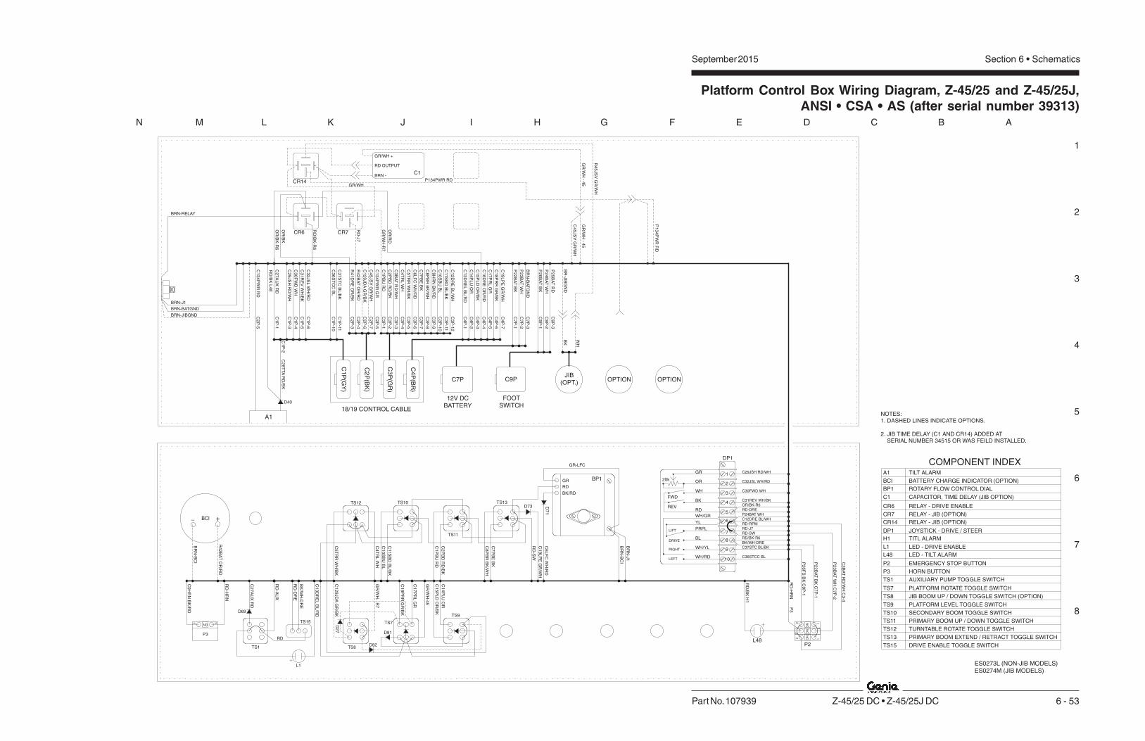
Section 6 • SchematicsSeptember 2015
1
2
3
4
5
6
7
8
N M L K J I H G F E D C B A
Part No. 107939 Z-45/25 DC • Z-45/25J DC 6 - 53
Platform Control Box Wiring Diagram, Z-45/25 and Z-45/25J,ANSI • CSA • AS (after serial number 39313)
OR
/BK
OR
/BK
-R6
GR
/WH
-R7
RD
-J7
C2
7A
UX
RD
C2
9JS
HR
D/W
H
C3
0F
WD
WH
C3
1R
EV
WH
/BK
C3
2JS
LW
H/R
D
C3
6S
TC
CB
L
C3
7S
TC
BL
/BK
R4
1D
RE
OR
/BK
C1
29
JD
AG
R/B
K
C4
5JS
VG
R/W
H
C1
PB
UR
D
C2
PB
DR
D/B
K
C3
BA
TR
D/W
H
C4
TR
LW
H
C5
TR
RW
H/B
K
C6
LF
CW
H/R
D
C7
PB
EB
K
C8
PB
RB
K/W
H
C9
HR
NB
K/R
D
C11
SB
DB
L/B
K
C1
0S
BU
BL
C1
2D
RE
BL
/WH
C1
3D
RE
LB
L/R
D
C1
4P
LU
OR
C1
5P
LD
OR
/BK
C1
6D
RE
OR
/RD
C1
7P
RL
GR
C1
8P
RR
GR
/BK
C1
9L
PE
GR
/WH
P2
6B
AT
BK
P2
5B
AT
RD
P2
4B
AT
WH
BR
-JIB
GN
D
BRN-J1
BRN-BATGND
BRN-JIBGND
C2
8T
TA
RD
/BK
C1
P-1
C1
P-3
C1
P-4
C1
P-5
C1
P-2
C1
P-6
C1
P-1
0
C1
P-1
1
C2
P-3
C2
P-6
C2
P-7
C3
P-1
C3
P-2
C3
P-3
C3
P-4
C3
P-5
C3
P-6
C3
P-7
C3
P-8
C3
P-9
C3
P-1
0
C3
P-1
1
C3
P-1
2
C4
P-1
C4
P-2
C4
P-3
C4
P-4
C4
P-5
C4
P-6
C4
P-7
C9
P-1
C9
P-2
C9
P-3
R4
2B
AT
OR
/RD
C2
P-4
C1
P(G
Y)
C2
P(B
K)
C4
P(B
R)
C3
P(G
R)
BK
WH
C1
34
PW
RR
D
BR
N-B
AT
GN
D
P2
2B
AT
BK
P2
3B
AT
WH
C7
P-1
C7
P-2
C7
P-3
OR
/RD
RD
/BK
-R6
BRN-RELAY
C9
HR
NB
K/R
D
RD
-HR
N
C2
7A
UX
RD
RD
-AU
X
RD
-DR
E
BK
/WH
-DR
E
C1
3D
RE
LB
L/R
D
C1
29
JD
AG
R/B
K
C1
8P
RR
GR
/BK
C1
7P
RL
GR
C1
5P
LD
OR
/BK
C1
4P
LU
OR
C32JSL WH/RD
C29JSH RD/WH
C30FWD WH
C31REV WH/BK
OR/BK-R6
RD-DRE
C12DRE BL/WH
RD-J7
RD-SW
RD/BK-R6
BK/WH-DRE
C37STC BL/BK
C36STCC BL
P2
3B
AT
WH
C7
P-2
C3
BA
TR
D/W
HC
3-3
P2
2B
AT
BK
C7
P-1
P2
6F
SB
KC
9P
-1
C5
TR
RW
H/B
K
C4
TR
LW
H
C1
0S
BU
BL
C2
PB
DR
D/B
K
C8
PB
RB
K/W
H
C7
PB
EB
K
RD
-SW
C1
9L
PE
GR
/WH
C6
LF
CW
H/R
D
TS12 TS10
TS11
TS13
TS8
TS7
TS9
TS1
P3RD
BR
N-B
CI
GR-LFC
RD-RPM
RD
/BK
H1
GR
/WH
-45
L1
1
2
3
4
5
6
7
8
9
10
FWD
REV
20k
LIFT
DRIVE
RIGHT
LEFT
DP1
34
NO
BR
N-J
1
C1
PB
UR
D
C11
SB
DB
L/B
K
P2
RD
-HR
N
P24BAT WH
GR
/WH
-R
7
R4
2B
AT
OR
/RD
BR
N-B
CI
A1
BP1
DP1
P2
P3
TS1
TILT ALARM
ROTARY FLOW CONTROL DIAL
JOYSTICK - DRIVE / STEER
EMERGENCY STOP BUTTON
HORN BUTTON
AUXILIARY PUMP TOGGLE SWITCH
COMPONENT INDEX
TS7
TS8
TS9
TS10
TS11
TS12
TS13
TS15
PLATFORM ROTATE TOGGLE SWITCH
JIB BOOM UP / DOWN TOGGLE SWITCH (OPTION)
PLATFORM LEVEL TOGGLE SWITCH
SECONDARY BOOM TOGGLE SWITCH
PRIMARY BOOM UP / DOWN TOGGLE SWITCH
TURNTABLE ROTATE TOGGLE SWITCH
PRIMARY BOOM EXTEND / RETRACT TOGGLE SWITCH
DRIVE ENABLE TOGGLE SWITCH
NOTES:1. DASHED LINES INDICATE OPTIONS.
2. JIB TIME DELAY (C1 AND CR14) ADDED ATSERIAL NUMBER 34515 OR WAS FEILD INSTALLED.
CR7CR6
RD
/BK
L4
8
D40
A1
C2
P-5
L48
12
NC
12 NC
1
2
NC
P3
H1 TITL ALARM
TS15
- +
CR6 RELAY - DRIVE ENABLE
CR7 RELAY - JIB (OPTION)
BCI BATTERY CHARGE INDICATOR (OPTION)
18/19 CONTROL CABLE
C7P C9P
12V DCBATTERY
FOOTSWITCH
JIB(OPT.)
OPTION OPTION
L1 LED - DRIVE ENABLE
L48 LED - TILT ALARM
GR
OR
WH
BK
RD
WH/GR
YL
PRPL
BL
WH/YL
WH/RD
BP1GR
RD
BK/RD
BCI
D2
7
D82
D81
D69
D7
1
D73
CR14GR/WH
C1
P134PWR RD
GR
/WH
-4
5
C4
5JS
VG
R/W
H
GR
/WH
-4
5
R4
5JS
VG
R/W
H
P1
34
PW
RR
D
GR/WH +
RD OUTPUT
BRN -
C1 CAPACITOR, TIME DELAY (JIB OPTION)
CR14 RELAY - JIB (OPTION)
ES0273L (NON-JIB MODELS)ES0274M (JIB MODELS)
C1
34
PW
RG
RC
2P
-5

September 2015 Section 6 • Schematics
6 - 546 - 53
Platform Control Box Wiring Diagram, Z-45/25 and Z-45/25J,ANSI • CSA • AS (after serial number 39313)

Section 6 • Schematics September 2015
6 - 55 6 - 56
Electrical Schematic, Z-45/25 and Z-45/25J, CE(after serial number 39313)

Section 6 • Schematics September 2015
1
2
3
4
5
6
7
8
A B C D E F G H I J K L M N
6 - 56 Z-45/25 DC • Z-45/25J DC Part No. 107939
Electrical Schematic, Z-45/25 and Z-45/25J, CE(after serial number 39313)
P2
2L
SB
K
L48
C1
33
PL
AB
L/R
DC
2P
-1C
2B
-1
C32
U6ACURTIS 1244
SEPEX CONTROLLER
F4500A
1
2
C3
B-9
C1
B-1
2
D2
H2
GR/BK
WH
TB134
C1P-12C132PLI GR
C7
B-1
C7
B-2
C7
P-2
P2
3B
AT
WH
OROR
C6
B-4
0O
R
C6
B-2
4
C4
0L
SO
RC
2P
-2C
2B
-2
TB40
C29JSH RD/WH
C32JSL WH/RD
C30FWD WH
C31REV WH/BK
BK
2G
AC
HA
SS
ISG
RO
UN
D
BK
-6
WH
-7
BK
-5
WH
-5
WH
-4
WH
-5
BK
-5
RD
RD
/BK
P26BAT
WH
-6
13LS1
(EXT)14
1
P22BAT BK C7P-1
HO
RN
C8
-BC
8-A
C8
-C
P42BAT OR/RD C6B-3
C6
B-2
5C
FIL
BK
C6B-22
C12DRE BL/WH
C6
B-1
2
BK
C6
B-2
0R
D
C11
-3
C11
-4
C11
-1
C11
-2C
10
-2
C1
0-1
C1
0-4
C1
0-3
BK
BK
BK
-7
C6
B-3
4
C6
B-9
BK
/RD
C6
B-2
8
C6
B-2
9
C6
B-3
2
C6
B-3
1
C6
B-3
0
C7
B-4
P1
82
BA
TR
D
C2
B-4
C3
B-3
C1
B-2
C2
B-5
C1
B-3
C1
B-4
C1
B-5
C1
B-6
C9P-2
C9P-3
R4
2B
AT
OR
/RD
C2
P-4
C3
BA
TR
D/W
HC
3P
-3
C2
8T
TA
RD
/BK
C1
P-2
P1
34
PW
RG
RC
2P
-5
C9
HR
NB
K/R
DC
3P
-9
C2
9JS
HR
D/W
HC
1P
-3
C3
2JS
LW
H/R
DC
1P
-6
C3
1R
EV
WH
/BK
C1
P-5
CR5
PR3
PR2
PR3
PR2
BK
P42BAT OR/RD
R42BAT OR/RD
P24BAT WH
RD
C12DRE BL/WH
BK
(GND)
TILTALARM
RD
WH-(FS)
FS1
H1
RD-(FS)
PLATFORM
GROUND
P1
KS1
TB22
P3HORN
P2
C9P-1 BK+
RD
P182BAT RD
BK-(FS)
OR
/RD
CR1
CR2
TB42
RD
/WH
30
8785
86
30
87
86
85
BR
N
BR
N
HM
CO
IL-P
R1
OF
F-L
MT
SP
DIN
P
INT
ER
LO
CK
53 17
BK
/RD
BK
-4
LS4(SEC)
BL
/WH
OR
/RD
LS2(PRI)
TB23
RD
/BK
OR
/RD
C6
B-3
9C
R5
RD
/BK
OR
/RD
20
CR
5
_
+
22
21
22
21
86
85
CB1
10A
C1
P-4
RD
20
AP2
24 V
FO
RW
AR
D
PO
T.
LO
W
DIO
DE
RE
TU
RN
+4
8V
INP
UT
PO
T.
HI
RE
VE
RS
E
101 9 11 1614
PR1
AP2 48V
OR
/RD
WH
WH
/BK
WH
/RD
RD
/WH
F1200A
F510A
F2200A
LEFTBOX
+48 V
C3
0F
WD
WH
2
CR
14
8V
DC
PO
WE
RR
EL
AY
FL
AS
HIN
GB
EA
CO
N(O
PT
ION
)
CR
24
8V
DC
PO
WE
RR
EL
AY
FB
+
HO
UR
ME
TE
R
HO
RN
RE
LA
Y
BA
SE
CO
NT
RO
LB
OX
GR
OU
ND
CR4
TIL
TS
EN
SO
RR
D
WH
BK
BR
N
F1
+
86
85
30
87
RIGHTMOTOR
BR
N
CR
5B
RA
KE
RE
LE
AS
EC
OIL
PR
1S
EP
EX
CO
NT
RO
LL
ER
CO
NTA
CT
OR
CO
IL
AP1
AU
XIL
IAR
YL
IFT
PU
MP
PR
IMA
RY
LIF
TP
UM
P
PR3 PR2
WH
BK
AC POWER
F2 F1
A2
A1
A2
A1+
_
PUMPPUMP
CH
AR
GE
R
LEFTMOTOR
RIGHTBOX
GR
OU
ND
+24 V
SWITCH SHOWN WITH BOOM EXTENDED.
NOTES:1. ALL LIMIT SWITCHES SHOWN WITH BOOM IN STOWED POSITION EXCEPT AS NOTED.2. ALL SOLENOID AND RELAY COILS ARE 24V DC SXCEPT WHERE NOTED.
F2
F2F1 B+M-AP1 B-
P134PWR RD
R42BAT OR/RD
C3
0F
WD
C3
1R
EV
C3
2JS
L
C2
9JS
H
C1
2F
TS
C4
0L
S
C1
79
DP
RG
R
+ _
+ _
+ _
+ _
+ _
+ _
+ _
+ _
1 3
5
7
812
6
4
D79
L37
ES0273L (NON-JIB MODELS)ES0274M (JIB MODELS)
DRIVELIGHTSTS48
WORKLIGHTSTS49
CR45
30
87
86
85
C2
P-1
1C
2B
-11
C2
P-1
2C
2B
-12
BK
(16
/2)
WH
(16
/2)
L30L30
WH
(16
/2)
WH
(16
/2)
BK
BK
CR23
30
87
86
85
F187A
48V
(AP2)
L29L29
WH
(16
/2)
WH
(16
/2)
BK
BK
WO
RK
LIG
HT
S(O
PT
ION
)
DR
IVE
LIG
HT
S(O
PT
ION
)
C40LS OR
3
ADD D40 ONLY IF UNIT HAS L4 AND L48. 4
L48 TILT ALARM LED. (OPTION)
SWITCH SHOWN WITH BOOM ROTATED PAST EITHER NON-STEER WHEEL.
H6
+L45
U33
L4
2D40
3
LS18A
D39
D88
LS18BOR
WH
BK
RD
BK
RD
R20
4.7K�
COM
NO
U3530A
2 SEC.5
2 9
8
3
+
-
D90

Section 6 • SchematicsSeptember 2015
1
2
3
4
5
6
7
8
N M L K J I H G F E D C B A
Part No. 107939 Z-45/25 DC • Z-45/25J DC 6 - 57
Electrical Schematic, Z-45/25 and Z-45/25J, CE(after serial number 39313)
PR3
CR20
LVI/BCI OPTION
RE
TR
AC
T
(GND)
PR3
PR2
BK
C1
4-1
C1
5-1
C1
9-1
C1
8-1
TU
RN
TA
BL
ER
OTA
TE
LE
FT
C1
4-2
TU
RN
TA
BL
ER
OTA
TE
RIG
HT
DE
SC
EN
TA
LA
RM
(OP
TIO
N)
SE
CO
ND
AR
YB
OO
MD
OW
N
SE
CO
ND
AR
YB
OO
MU
P
C1
5-2
C1
9-2
H4
+
C1
8-2
C6
B-5
WH
/BK
C6
B-4
WH
TB4
C6
B-1
1B
L/B
K
C6
B-1
0B
L
TB5TB11 TB10
C2
1-1
C2
0-1
C1
7-1
C1
6-1
C1
2-1
C1
3-1
PR
IMA
RY
BO
OM
UP
PR
IMA
RY
BO
OM
DO
WN
PR
IMA
RY
BO
OM
RE
TR
AC
T
PR
IMA
RY
BO
OM
EX
TE
ND
C1
2-2
C1
3-2
C1
6-2
C1
8-2
PL
AT
FO
RM
LE
VE
LD
OW
N
PL
AT
FO
RM
LE
VE
LU
P
C2
1-2
C2
0-2
C6
B-8
BK
/WH
C6
B-7
BK
C6
B-2
RD
/BK
C6
B-1
RD
TB2 TB1 TB8TB7
C6
B-1
5O
R/B
K
C6
B-1
4O
R
TB15TB14
C2
2-1
C2
3-1
PL
AT
FO
RM
RO
TA
TE
RIG
HT
(JIB
DO
WN
-O
PT.)
PL
AT
FO
RM
RO
TA
TE
LE
FT
(JIB
UP
-O
PT
ION
)
CR
20
PR
IMA
RY
PU
MP
CO
NTA
CT
OR
RE
LA
Y
PR
OP
OR
TIO
NA
LF
LO
WC
ON
TR
OL
PR
3A
UX
ILIA
RY
PU
MP
CO
NTA
CT
OR
RE
LA
Y
C2
3-2
C2
2-2
C4
4D
AB
K
RD
C6
B-6
WH
/RD
C6
B-1
7G
R
C6
B-1
8G
R/B
K
C6
B-2
7
GR
/WH
86
85
TB17TB18
GR/WH
30
87a 87
TB6
TB19
CR19A
PRIMARYBOOM
P42BAT OR/RD
TS55
C12DRE BL/WH
RD
CR5
WH
C2
PB
DR
D/B
K
C1
0S
BU
BL
C11
SB
DB
L/B
K
C4
TR
RW
H/B
K
C4
TR
LW
H
RIG
HT
TURNTABLEROTATE
FUNCTIONENABLE
LE
FT
TS62
RD
C3
B-4
C3
B-5
SECONDARYBOOM
TS60
DO
WN
UP
C3
B-1
1
C3
B-1
0
C3
B-1
C3
B-2
C3
P-4
C3
P-5
LE
FT
TS12
RIG
HT
TURNTABLEROTATE
C3
P-1
0
C3
P-1
1
C1
PB
UR
D
C3
P-2
C3
P-1
SECONDARYBOOM
DO
WN
87A
30
CR19B
UP
TS10
DO
WN
87A
30
TS11
UP
C30FWD WH
C29JSH RD/WH
C31REV WH/BK
C32JSL WH/RD
R42BAT OR/RD
P24BAT WH
WHPLATFORM
ROTATE
C4
5JS
VG
R/W
H
C1
5P
LD
OR
/BK
C1
4P
LU
OR
C7
PB
EB
K
C8
PB
RB
K/W
H
DO
WN
TS61
UP
PRIMARYBOOMBOOM
TS63
EX
TE
ND
PRIMARYBOOM
C3
B-7
C3
B-8
PLATFORMLEVEL
DO
WN
TS59
C2
B-7
UP
GR/WH
C4
B-3
C4
B-2
C3
P-7
C3
P-8
EX
TE
ND
PRIMARYBOOM
RE
TR
AC
T
TS13
DO
WN
TS9
C4
P-3
C4
P-2
C2
P-7
PLATFORMLEVEL
UP
LE
FT
TS7
C1
29
JD
AG
R/B
K
JIB
MA
NIF
OL
D
C1
7P
RL
GR
C1
8P
RR
GR
/BK
C6
LF
CW
H/R
D
C1
9L
PM
PG
R/W
H
TB44
PLATFORMROTATE
LE
FT
TS57
C4
B-6
GR
/BK
C4
B-5
GRR
IGH
T
BK
CR7
C2
B-6
UP
TS58
DO
WN
JIBBOOM C
4B
-7G
R/W
H
C3
B-6
WH
/RD
RD
C4
P-5
C4
P-6
C2
P-6
87a
RIG
HT
30
DO
WN
UP
TS8
JIBBOOM
ROTARYOEMFLOWCONTROL
BP1
C4
P-7
C3
P-6
BK
CR19A
CR19B5
1
6 7
32
8
4
C7
P-3
BA
TG
ND
BR
N
C6
B-1
3C
13
DR
EL
C6
B-1
6C
16
DR
E
C6
B-2
6C
12
DR
E
RD
/WH
C6
B-3
5
PS
1
C6
B-3
6B
LS
TE
ER
LE
FT
C2
5-1
C6
B-1
9
GR
/WH
CR
3A
UX
ILIA
RY
PU
MP
CO
NTA
CT
OR
CO
IL
PR
2P
RIM
AR
YP
UM
PC
ON
TA
CT
OR
CO
IL
BK
PR2
ST
EE
RR
IGH
T
C2
5-2
87
30
86CR3
85
RD
GR/WH
OR
/RD
C6
B-3
7B
L/B
K
C6B-38 GR/WH
TB37
C2
6-1
C2
4-1
C7
B-3
BA
TG
ND
BR
N
C6
B-2
1D
RE
GN
DB
RN
TR
AV
EL
AL
AR
M
N.C
.B
RA
KE
RE
LE
AS
EV
ALV
E
PS
1B
RA
KE
PR
ES
SU
RE
SW
ITC
H
C2
4-2
C2
6-2
+
H3
TB36
RD
/WH
RD
/WH
13
DR
IVE
EN
AB
LE
LIM
ITS
WIT
CH
RD
-8
BR
N-8
LS3
14 21
22
WH
-8
BK
-8
DP1
RD
C3
7S
CW
BL
/BK
TS51
TB27
AUXILIARYPUMP
RD
OR/RD
BRN
C1
B-1
C1
B-1
1
AUXILIARYPUMP
+
E
F
BCIOPTION
C2
7A
UX
RD
C1
P-1
OR
/RD
TS1
RD
-AU
X
STEER
L R10
9
C1
P-1
1
C1
P-1
0OR/BK-R6
4
LIFT
DRIVE
REV
8
7
6
5
FWD
20K
3
2
1
C1
3D
RE
LB
L/R
D
C1
2D
RE
BL
/WH
C1
6D
RE
OR
/RD
R4
1D
RE
OR
/BK
C4
B-4
TB12
OR
/RD87
30
CR5
CR5
C1
B-1
0
C2
B-3
BR
N
BL
/WH
BR
N
BL
/RD
C3
B-1
2
C4
B-1
C4
P-4
DRIVEENABLE
C2
P-3
87
C3
6S
CC
BL
TS15 30CR6
85
86
RD/BK-R6
C3
P-1
2
C4
P-1
L1DRIVEENABLELED
C40LS OR
P24BAT WH
C29JSH RD/WH
C32JSL WH/RD
C30FWD WH
C31REV WH/BK
4
WH
CR14
P134PWR RD
WH
GR
/WH
RD
GR/WHGR/WH
BR
BRN
WH/RD85
85 86
86
4
BRN
RD
GR
BK/RD
86
85
85
86
C1
+
_
30
87A
33�
33�
C4
4D
A
C129JDA BK
D81 D82
D27
D73
D69
D78
D85
D60
D59
D76
D4
D74
D72
D28D82
D80
D50
D30
D29
D71
C40LS OR
87
30CR8
85
86

September 2015 Section 6 • Schematics
6 - 586 - 57
Electrical Schematic, Z-45/25 and Z-45/25J, CE(after serial number 39313)

Section 6 • Schematics September 2015
6 - 59 6 - 60
Ground Control Box Terminal Strip Wiring Diagram,Z-45/25 and Z-45/25J, CE (after serial number 39313)

Section 6 • Schematics September 2015
1
2
3
4
5
6
7
8
A B C D E F G H I J K L M N
6 - 60 Z-45/25 DC • Z-45/25J DC Part No. 107939
Ground Control Box Terminal Strip Wiring Diagram,Z-45/25 and Z-45/25J, CE (after serial number 39313)
DC
PR
IMA
RY
BO
OM
UP
1 2 4 5 6 7 8 10
PR
IMA
RY
BO
OM
DO
WN
TU
RN
TA
BL
ER
OTA
TE
LE
FT
TU
RN
TA
BL
ER
OTA
TE
RIG
HT
LIF
TF
LO
WC
ON
TR
OL
PR
IMA
RY
BO
OM
EX
TE
ND
PR
IMA
RY
BO
OM
RE
TR
AC
T
SE
CO
ND
AR
YB
OO
MU
P
LIF
TP
UM
P
LIF
TP
UM
P
PL
AT
FO
RM
LE
VE
LD
OW
N
PL
AT
FO
RM
LE
VE
LU
P
FO
OT
SW
ITC
HP
OW
ER
#2
SE
CO
ND
AR
YB
OO
MD
OW
N
19
1911
15
17
18
14
12
AU
XIL
IAR
YP
UM
PS
EL
EC
T
KE
YS
WIT
CH
PO
WE
R
+2
4V
DC
TO
PL
AT
FO
RM
27
22
23
ST
EE
RR
IGH
T
ST
EE
RL
EF
T
34
36
37
35
33
OF
F-L
IMIT
SP
EE
D4
0
BA
C3
B-1
C1
PB
UR
DR
D-T
S6
1
RD
/BK
-TS
61
WH
-TS
62
WH
/BK
-TS
62
BK
-TS
63
BK
/WH
-TS
63
BL
-TS
60
BL
/BK
-TS
60
C1
2D
RE
BL
/WH
OR
-TS
59
WH
-HM
OR
/BK
-TS
59
GR
-TS
57
GR
/BK
-TS
57
GR
/WH
GR
/WH
-J1
9
WH
-KS
1(D
2)
RD
-CR
3
GR
/WH
-J1
9
GR
/WH
-J1
9
OR
/RD
-LE
D
OR
/RD
-CR
1
GR
/WH
RD
-TS
51
GR
/WH
-TS
60
L3
7
TE
RM
INA
LB
AS
E(T
B)
1 2 4 5 6 7 8 10
19
1911
15
17
18
14
12
27
22
23
34
36
37
35
33
42
40
GR
OU
ND
CO
NT
RO
LH
AR
NE
SS
TO
SW
ITC
HP
AN
EL
GR
/BK
-TS
58
OR
/RD
CR
4H
OR
NR
EL
AY
RD
/WH
OR
/RD
CR
14
8V
DC
PO
WE
RR
EL
AY
CR
24
8V
DC
PO
WE
RR
EL
AY
87
a
30
86
85
BR
N
87
BK
87
87
a8
58
6
30
BR
N
CR
20
RE
LA
YL
IFT
PU
MP
OR
/RD
BR
N
87
a8
6
30 8
5
87
BRN
OR
/RD
RD/BK
OR/BK
RD/WH
OR/RD
87
87
a8
5
30
86
GR/WH
CR
3
RE
LA
YA
UX
ILIA
RY
CO
NT
RO
L
BR
N
87
a8
6
30 8
5
RD
87
GR
/WH
BRN
CR
5B
RA
KE
RE
LE
AS
ER
EL
AY
GR
/WH
87
a8
6
30 8
5
87
C9
HR
NB
K/R
D
C6
B-9
R9
HR
N
C6
B-3
9C
R5
RD
/BK
C2
B-3
C4
1D
RE
OR
/BK
C6
B-3
5R
48
BR
KR
D/W
H
C3
B-3
C3
BA
TR
D/W
H
C6
B-3
P4
2B
AT
OR
/RD
C6
B-2
7R
27
AU
X
C6
B-1
9R
19
LP
EG
R/W
H
C3
B-2
C2
PB
DR
D/B
K
C3
B-4
C4
TR
LW
H
C3
B-5
C5
TR
RW
H/B
K
C3
B-6
C6
LF
CW
H/R
D
C3
B-7
C7
PB
EB
K
C3
B-8
C8
PB
RB
K/W
H
C3
B-1
0C
10
SB
UB
L
C3
B-1
1C
11
SB
DB
L/B
K
C3
B-1
2C
12
DR
EB
L/W
H
C4
B-2
C1
4P
LU
OR
C4
B-3
C1
5P
LD
OR
/BK
C4
B-5
C1
7P
RL
GR
C4
B-6
C1
8P
RR
GR
/BK
C4
B-7
C1
9L
PE
GR
/WH
C1
B-1
C2
7A
UX
RD
C1
B-1
1C
37
ST
CB
L/B
K
C1
B-1
0C
36
ST
CC
BL
C2
B-4
R4
2B
AT
OR
/RD
C2
B-6
C1
29
DA
GR
/BK
C6
B-1
C1
PB
UR
D
C6
B-2
C2
PB
DR
D/B
K
C6
B-4
C4
TR
LW
H
C6
B-5
C5
TR
RW
H/B
K
C6
B-6
C6
LF
CW
H/R
D
C6
B-7
C7
PB
EB
K
C6
B-8
C8
PB
RB
K/W
H
C6
B-1
0C
10
SB
UB
L
C6
B-1
1C
11
SB
DB
L/B
K
C6
B-1
4C
14
PL
UO
R
C6
B-1
5C
15
PL
DO
R/B
K
C6
B-1
7C
17
PR
LG
R
C6
B-1
8C
18
PR
RG
R/B
K
C6
B-3
8C
19
LP
EG
R/W
H
C6
B-2
0P
22
LS
BK
C6
B-3
6C
36
ST
CC
BL
C6
B-3
7C
37
ST
CB
L/B
K
C6
B-2
2R
42
BA
TO
R/R
D
BK
-CR
4
C28TTA RD/BK
C29JSH RD/WH
C30FWD WH
C31REV WH/BK
C32JSL WH/RD
C16DRE OR/RD
C13DREL BL/RD C4B-1
C4B-4
C6
B-2
5
C6
B-2
6C
12
DR
EB
L/W
H
C3
B-9
C6B-13
C6B-16
C6B-28
C6B-29
C6B-30
C6B-31
C6B-32
P1
82
BA
TR
D
C7
B-2
P2
3B
AT
WH
GR
OU
ND
ST
UD
C7B-3 BATGND BRN
BR
N
P182BAT RD C7B-4
BK
OR
/RD
OR
/RD
GR
/WH
-CR
3
C6
B-1
2C
12
DR
EB
L/W
H
OR
/RD
-42
A
C6
B-3
3C
12
9D
AR
D/B
K
PL
AT
FO
RM
RO
TA
TE
RIG
HT
/JIB
DO
WN
PL
AT
FO
RM
RO
TA
TE
LE
FT
/JIB
UP
D5
0C
12
9D
AR
D/B
K
D3
0C
12
9D
AR
D/B
K
C1
29
DA
RD
/BK
C129DA RD/BK
JIB
DE
SC
EN
TA
LA
RM
44
44
C2
B-2
C4
0L
SO
R
SW
ITC
H4
8V
OLT
S4
2
C6
B-2
4C
40
LS
OR
C6
B-4
0C
40
LS
OR
BR
N
BK/RD
RD
GR/WH
RD/WH
C6B-21
BR
N
GR
/WH
C2
B-7
C4
5JS
VG
R/W
H
BR
N-H
M
BK
BRN
BK
-KS
1
BRN GND
GR/BK H6
RD TS55
RD TS51
BK C7-1
BK 22D
BL/WH C1-12
RD H6
U3
3
13
45
67
81
2
C2
3-4
P2
2B
AT
BK
KE
YS
WE
ITC
HP
OW
ER
13
41
34
RD
KS
1
RD
H6
C6
B-3
4C
13
4P
WR
RD
C2
B-5
P1
34
BA
TR
D
RD
13
4B
RD
C3
2-1
GR
/BK
L4
5
GR
/BK
C3
2-8
GR
/BK
C2
B-6
H6
C3
2
D7
2
D7
4
D6
0
D5
9
D7
8
D7
6
D8
5
C7
C6
C4BBROWN
C3BGREEN
C2BBLACK
C1BGRAY
C1B-2
C1B-3
C1B-4
C1B-5
C1B-6
ES0273L (NON-JIB MODELS)ES0274M (JIB MODELS)
D5
9

Section 6 • SchematicsSeptember 2015
1
2
3
4
5
6
7
8
N M L K J I H G F E D C B A
Part No. 107939 Z-45/25 DC • Z-45/25J DC 6 - 61
Ground Control Box Switch Panel Wiring Diagram,Z-45/25 and Z-45/25J, CE (after serial number 39313)
TS
57
TS
59
TS
58
TS
51
TS
60
TS
61
TS
63
TS
62
P1
CB
1
RD
C45JSV GR/WH (C2B-7)
BK
RD
BK
BK
GR
GR
/BK
WH-4A
WH/BK-5A
RD
BK
BK/WH-8A
BK-7A
RD
RD-27A
RD-1A
RD/BK-2A
RD
BK
BK
RD
GR/BK
GR
GR
BK
P182BAT RD (C7B-4)
RD
BK
BL-10A
BL/BK-11A
GR/WH-19A BK
RD
RD
RD
RD
RD
RD
WH
-HM
BK
BA
SE
BO
XH
AR
NE
SS
GR/BK-18A
RD
RD
GR/BK-44A
1
2
NC
GR-17A
RD
RD
WH
BRN
RD
RD
OR/BK-15A
OR-14A
OR/BK
OR
TS
55
BR
N-H
M
KS
1
-
+
RD C23-6
BK-22A
RD C23-7
RD
L4
5
D2
RD 134A
WH
WH 23A
GR/BK H6
RD
CB1
CR1
CR2
CR3
CR4
CR5
CR20
H6
KS1
10A CIRCUIT BREAKER
POWER RELAY, 48V
POWER RELAY, 48V
AUXILIARY PUMP RELAY
HORN RELAY
BRAKE RELEASE RELAY
PRIMARY LIFT PUMP RELAY
PLATFORM OVERLOAD ALARM
KEY SWITCH
COMPONENT INDEX
L37
P1
TS51
TS55
TS57
TS58
TS59
TS60
LED - DRIVE CONTROLLER FAULT STATUS
EMERGENCY STOP BUTTON
AUXILIARY PUMP TOGGLE SWITCH
FUNCTION ENABLE TOGGLE SWITCH
PLATFORM ROTATE TOGGLE SWITCH
JIB UP / DOWN TOGGLE SWITCH (OPTION)
PLATFORM LEVEL UP / DOWN TOGGLE SWITCH
SECONDARY BOOM UP / DOWN TOGGLE SWITCH
TS61
TS62
TS63
PRIMARY BOOM UP / DOWN TOGGLE SWITCH
TURNTABLE ROTATE TOGGLE SWITCH
PRIMARY BOOM EXTEND / RETRACT TOGGLE SWITCH
G6 ES0273L (NON-JIB MODELS)
ES0274M (JIB MODELS)
D80
D82
D28
D4
G6 HOUR METER
L45 LED - PLATFORM OVERLOAD
U33 LOAD SENSE MODULE
NOTE: DASHED LINES INDICATE OPTIONS.

September 2015 Section 6 • Schematics
6 - 62
Ground Control Box Switch Panel Wiring Diagram,Z-45/25 and Z-45/25J, CE (after serial number 39313)
6 - 61

Section 6 • Schematics September 2015
6 - 63
Platform Control Box Wiring Diagram, Z-45/25 and Z-45/25J,CE (after serial number 39313)
6 - 64

Section 6 • Schematics September 2015
1
2
3
4
5
6
7
8
A B C D E F G H I J K L M N
6 - 64 Z-45/25 DC • Z-45/25J DC Part No. 107939
OR
/BK
OR
/BK
-R6
GR
/WH
-R7
RD
-J7
C2
7A
UX
RD
C2
9JS
HR
D/W
H
C3
0F
WD
WH
C3
1R
EV
WH
/BK
C3
2JS
LW
H/R
D
C3
6S
TC
CB
L
C3
7S
TC
BL
/BK
R4
1D
RE
OR
/BK
C1
29
JD
AG
R/B
K
C4
5JS
VG
R/W
H
C1
PB
UR
D
C2
PB
DR
D/B
K
C3
BA
TR
D/W
H
C4
TR
LW
H
C5
TR
RW
H/B
K
C6
LF
CW
H/R
D
C7
PB
EB
K
C8
PB
RB
K/W
H
C9
HR
NB
K/R
D
C11
SB
DB
L/B
K
C1
0S
BU
BL
C1
2D
RE
BL
/WH
C1
3D
RE
LB
L/R
D
C1
4P
LU
OR
C1
5P
LD
OR
/BK
C1
6D
RE
OR
/RD
C1
7P
RL
GR
C1
8P
RR
GR
/BK
C1
9L
PE
GR
/WH
P2
6B
AT
BK
P2
5B
AT
RD
P2
4B
AT
WH
BR
-JIB
GN
D
BRN-J1
BRN-BATGND
BRN-JIBGND
C2
8T
TA
RD
/BK
C1
P-1
C1
P-3
C1
P-4
C1
P-5
C1
P-2
C1
P-6
C1
P-1
0
C1
P-1
1
C2
P-3
C2
P-6
C2
P-7
C3
P-1
C3
P-2
C3
P-3
C3
P-4
C3
P-5
C3
P-6
C3
P-7
C3
P-8
C3
P-9
C3
P-1
0
C3
P-1
1
C3
P-1
2
C4
P-1
C4
P-2
C4
P-3
C4
P-4
C4
P-5
C4
P-6
C4
P-7
C9
P-1
C9
P-2
C9
P-3
R4
2B
AT
OR
/RD
C2
P-4
C1
P(G
Y)
C2
P(B
K)
C4
P(B
R)
C3
P(G
R)
BK
WH
C1
34
PW
RR
D
BR
N-B
AT
GN
D
P2
2B
AT
BK
P2
3B
AT
WH
C7
P-1
C7
P-2
C7
P-3
OR
/RD
RD
/BK
-R6
BRN-RELAY
C9
HR
NB
K/R
D
RD
-HR
N
C2
7A
UX
RD
RD
-AU
X
RD
-DR
E
BK
/WH
-DR
E
C1
3D
RE
LB
L/R
D
C1
29
JD
AG
R/B
K
C1
8P
RR
GR
/BK
C1
7P
RL
GR
C1
5P
LD
OR
/BK
C1
4P
LU
OR
C32JSL WH/RD
C29JSH RD/WH
C30FWD WH
C31REV WH/BK
OR/BK-R6
RD-DRE
C12DRE BL/WH
RD-J7
RD-SW
RD/BK-R6
BK/WH-DRE
C37STC BL/BK
C36STCC BL
P2
3B
AT
WH
C7
P-2
C3
BA
TR
D/W
HC
3-3
P2
2B
AT
BK
C7
P-1
P2
6F
SB
KC
9P
-1
C5
TR
RW
H/B
K
C4
TR
LW
H
C1
0S
BU
BL
C2
PB
DR
D/B
K
C8
PB
RB
K/W
H
C7
PB
EB
K
RD
-SW
C1
9L
PE
GR
/WH
C6
LF
CW
H/R
D
TS12 TS10
TS11
TS13
TS8
TS7
TS9
TS1
P3RD
BR
N-B
CI
GR-LFC
RD-RPM
GR
/WH
-45
L1
1
2
3
4
5
6
7
8
9
10
FWD
REV
20k
LIFT
DRIVE
RIGHT
LEFT
DP1
34
NO
BR
N-J
1
C1
PB
UR
D
C11
SB
DB
L/B
K
P2
RD
-LS
18
P24BAT WH
GR
/WH
-R
7
R4
2B
AT
OR
/RD
BR
N-B
CI
A1
BP1
DP1
P2
P3
TS1
TILT ALARM
ROTARY FLOW CONTROL DIAL
JOYSTICK - DRIVE / STEER
EMERGENCY STOP BUTTON
HORN BUTTON
AUXILIARY PUMP TOGGLE SWITCH
COMPONENT INDEX
TS7
TS8
TS9
TS10
TS11
TS12
TS13
TS15
PLATFORM ROTATE TOGGLE SWITCH
JIB BOOM UP / DOWN TOGGLE SWITCH (OPTION)
PLATFORM LEVEL TOGGLE SWITCH
SECONDARY BOOM TOGGLE SWITCH
PRIMARY BOOM UP / DOWN TOGGLE SWITCH
TURNTABLE ROTATE TOGGLE SWITCH
PRIMARY BOOM EXTEND / RETRACT TOGGLE SWITCH
DRIVE ENABLE TOGGLE SWITCH
NOTES:1. DASHED LINES INDICATE OPTIONS.
CR7CR6
RD
/BK
L4
8
D40
A1
C2
P-5
12
NC
12 NC
1
2
NC
H1 TITL ALARM
TS15
- +
CR6 RELAY - DRIVE ENABLE
CR7 RELAY - JIB (OPTION)
BCI BATTERY CHARGE INDICATOR (OPTION)
18/19 CONTROL CABLE
C7P C9P
12V DCBATTERY
FOOTSWITCH
JIB(OPT.)
LS18 OPTION
L1 LED - DRIVE ENABLE
L4 LED - PLATFORM OVERLOAD
GR
OR
WH
BK
RD
WH/GR
YL
PRPL
BL
WH/YL
WH/RD
BP1GR
RD
BK/RD
BCI
D2
7
D82
D81
D69
D7
1
D73
CR14GR/WH
C1
P134PWR RD
GR
/WH
-4
5
C4
5JS
VG
R/W
H
GR
/WH
-4
5
R4
5JS
VG
R/W
H
P1
34
PW
RR
D
GR/WH +
RD OUTPUT
BRN -
C1 CAPACITOR, TIME DELAY (JIB OPTION)
CR14 RELAY - JIB (OPTION)
CR8
C4
0L
SO
RC
2P
-2
RD
-J7
P2
4B
AT
WH
BRN-RELAY
GR
/BK
-H1
(D3
9)
L4
C1
32
PL
I1G
RC
1P
-12
RD
CR8 RELAY - LIMIT SWITCH
LS18 PLATFORM OVERLOAD LIMIT SWITCH
C1
32
PL
I1B
L/W
HC
1P
-12
BK
U35
R2
0
2+
3- 5
P26BAT BK
P2
6B
AT
BK
P2
C3
BA
TR
D/W
HC
3B
-3
LS18 - BK
BK
C1
34
PW
RR
D
D88
D90
LS18 - WH
C134PWR RD
BR - GND
RD
C1
34
PW
RR
DL
S1
8A
OR
-L
S1
8A
R20 RESISTOR - 4700�
U35 TIME DELAY RELAY
ES0273L (NON-JIB MODELS)ES0274M (JIB MODELS)
Platform Control Box Wiring Diagram, Z-45/25 and Z-45/25J, CE(after serial number 39313)

Section 6 • SchematicsSeptember 2015
1
2
3
4
5
6
7
8
N M L K J I H G F E D C B A
Part No. 107939 Z-45/25 DC • Z-45/25J DC 6 - 65
DC AMMETER CABLE
AC POWER CABLE
CONTROLLER
BATTERY
BK
-FR
OM
CH
AR
GE
R
NOTES:1. ALL WIRE IS 16 GAUGE UNLESS OTHERWISE SPECIFIED.
LEFT SIDEDRIVE MOTOR
CHASSISGROUND
F1 A1
BK-2GA
BK-2GA
BRN-J8
BK-FROM CHARGER
BK-2GA
RD-2GA
RD-10GA
F2 A2
RD-2GA
RD-10GA
F2200A
48V DC
RD
-2G
A
BK
-2G
A
BK
-2G
A
BRN-J8
23
C3
1R
EV
WH
/BK
R27AUX RD
12
OR
/RD
BR
N-J
8
BK-2GA
RD-2GA
RD-10GA
BR
N-J
8
24
RD-2GA
RD-10GA
OR
/RD
RD
-2G
A
4 3 1267 511 10 9 8
F1 F2
SEPEX MOTOR CONTROLLER
B- M- B+
CF
ILB
K
R4
2B
AT
OR
/RD
C3
0F
WD
WH
R4
2B
AT
OR
/RD
C1
2D
RE
BL
/WH
C4
0L
SO
R
GR
CR
5R
D/B
K
2022 21 19 18
C2
9JS
HR
D/W
H
C3
2JS
LW
H/R
D
1617 15 1314
BRN-J8
RD
AP-2
-
+
-
+
-
+
-
+
+
_
LEFT SIDEBATTERY PACK
+
-
R42BAT OR/RD
R42BAT OR/RD
P42BAT OR/RD
RD-20-12GA
LIFT PUMPCONTACTOR
PR-2
DIODE
GR
/WH
-19
BK-2GA
BK-2GA
BK-2GA
RD-2GA
R42BAT OR/RD
PR-1
DRIVE CONTACTOR
F5 10A
PR-1
TOP VIEW OFDRIVE CONTACTOR
AUXILIARY LIFTPUMP
A2
D1
D1
PRIMARYLIFT PUMPA1
FUNCTION HARNESSTO GROUND CONTROL BOXCONNECTOR C6B
ACBATTERYCHARGER
RD-2GA
BK
-2G
A
RD
-2G
A
A1
BK-2GA
RD-2GA
RD-10GA
RD-2GA
RD-P182-12GA
RD
-2G
A
RIGHT SIDEDRIVE MOTOR
A2 F2
F1
F1200A
24V DC
BK-2GA
BK-2GA
AUXILIARY PUMPCONTACTOR
PR-3
+
-AP-1
RD
-2G
A
AMMETER
+
-
+
+
4
12
3
ACCHARGER
PLUG
-
5 6 7
89
-
+
-
-
+
-
RIGHT SIDEBATTERY PACK
+
BK BK BKBK
DIODE
DIODE
BK
WH
RD-10GA
F4500A
P4
2B
AT
OR
/RD
WH
-FR
OM
CH
AR
GE
R
33�
LEDCHARGERINDICATOR
33�
FOR REFERENCE ONLY - F4 MOUNTS ON PR-1
U6A
ES0273L (NON-JIB MODELS)ES0274 (JIB MODELS)
Power Cable Wiring Diagram

September 2015 Section 6 • Schematics
6 - 666 - 65
Power Cable Wiring Diagram

Section 6 • Schematics September 2015
6 - 67 6 - 68
CTE Option, CE

Section 6 • Schematics September 2015
1
2
3
4
5
6
7
8
A B C D E F G H I J K L M N
6 - 68 Z-45/25 DC • Z-45/25J DC Part No. 107939
CTE Option, CE
ES0276N
C21-1
SCHEMATIC - PLATFORM LEVEL CUTOUT
PL
AT
FO
RM
LE
VE
LD
OW
N
GROUND BR
BRN
C1
5P
LD
OR
/BK
CR18B
C1
5P
LD
OR
/BK
TB15
P22LS BK LIM
ITS
WIT
CH
ES
TB14
C1
4P
LU
OR
CR18A
C1
4P
LU
OR
TB40
LOAD WEIGHING LIM. SW. +12V (2)
LOAD WEIGHING LIM. SW. +12V (1)
BOOM STOWED
PLATFORM LEVEL DOWN
PLATFORM LEVEL UP
WIRING DIAGRAM
CR18APLATFORM LEVEL UP
OR-TS59
OR/BK-TS59
14
15
P22LS BK
P134FB WH-FHRD-KS
C40LS1 OR CR18A#3040
134
134
GROUND BOLT
C15PLD OR/BK C21-1
C14PLU OR C20-1
BRN
CR18BPLATFORM LEVEL DOWN
C15PLD OR/BK CR18B#86
C14PLU OR CR18A#86
C15PLD OR/BK C4B-3
C14PLU OR C4B-2
14
15
P134BAT BK-LS5 C37-3
P134TTS RD A
P134BAT RD-LS17 C38-1
C40LS1 OR C10-2
C40LS1 OR C2B-2
40
134
134
FU
NC
TIO
NH
AR
NE
SS
C21-2
C20-1
C20-2
PL
AT
FO
RM
LE
VE
LU
P

Section 6 • SchematicsSeptember 2015
1
2
3
4
5
6
7
8
N M L K J I H G F E D C B A
Part No. 107939 Z-45/25 DC • Z-45/25J DC 6 - 69
ES0276N
WIRING DIAGRAM
C6B-22 R42BAT OR/RD
SCHEMATIC
48V DCOUTPUT
BATTERY INDICATOR LED1. THE LED IS RED DURING PHASES I1 AND P (BULK CHARGE). (20% BATTERY CHARGED)2. THE LED IS YELLOW DURING PHASES U AND I2. (80% BATTERY CHARGED)3. THE LED IS GREEN AT THE END OF THE CHARGE. (100% BATTERY CHARGED)4. THE LED IS FLASHING GREEN DURING CYCLE EQUALIZATION.5. THE LED IS OFF WHEN THE CHARGER IS NOT POWERED ON.6. THE LED FLASHES RED. INDICATES A DEFECT.
INTERLOCK RELAY (N.O.), 10A CONTACT1. CHARGER NOT CONNECTED TO BATTERY OR MAIN SUPPLY, CONTACT OPEN.2. CHARGER CONNECTED TO BATTERY, CONTACT CLOSED.3. CHARGER CONNECTED TO BATTERY AND MAIN SUPPLY, CONTACT OPEN.
C56-1 BKC56-2 WH
DIODE
TOP VIEW OFDRIVE CONTACTOR
PR-1
DRIVE CONTACTOR
PR-1
14 131517 1618192122 20
C1
79
DP
RG
R
891011 57 6 2 134
24
12
23
BATTERY
CONTROLLER
C56-1 BK
ACBATTERYCHARGER
U6ACURTIS 1244
SEPEX MOTOR CONTROLLER
PR1COIL
53 17
GR
BK
20
DIO
DE
RE
TU
RN
+4
8V
INP
UT
101 9 11 1614
R4
2B
AT
OR
/RD
2
F2F1 B+M- B-
SEPEX MOTOR CONTROLLER
LEDCHARGERINDICATOR
BK
R42BAT OR/RDR42BAT OR/RD
C56-2 WH
ACBATTERYCHARGER
WH
R42BAT OR/RD
(N.O.)
WH
R42BAT OR/RD
Charger Interlock Option

September 2015 Section 6 • Schematics
6 - 706 - 69
Charger Interlock Option

Section 6 • Schematics September 2015
6 - 71 6 - 72
Platform Control Box LVI / BCI Option Wiring Diagram(before serial number 31015)

Section 6 • Schematics September 2015
1
2
3
4
5
6
7
8
A B C D E F G H I J K L M N
6 - 72 Z-45/25 DC • Z-45/25J DC Part No. 107939
Platform Control Box LVI / BCI Option Wiring Diagram(before serial number 31015)
C1
P(G
Y)
C2
P(B
K)
C4
P(B
R)
C3
P(G
R)
BRN-RELAY
TS12 TS10 TS11 TS13
TS8 TS7 TS9TS1
P3
TS15
L1
1
2
3
4
5
6
7
8
9
10
FWD
REV
20k
LIFT
DRIVE
RIGHT
LEFT
DP1
34 NO
P2
BCI
LVI
BATTERY CHARGE INDICATOR
LOW VOLTAGE INTERRUPT MODULE
COMPONENT INDEX
TS10
TS11
SECONDARY BOOM TOGGLE SWITCH
PRIMARY BOOM UP / DOWN TOGGLE SWITCH
1
2
3
4
5
6
7
8
12 NC
12 NC
RESET IS SET TO "B",DISCHARGE IS SET TO "N"
C4
0L
SO
R
RD
-LV
I
RD
-LR
19
B
BL
-L1
0
BL
-LR
19
A
R4
2B
AT
OR
/RD
OR
-LV
I
OR
/BK
-LV
I
OR
/RD
-LV
I
P2
4B
AT
WH
BR
N-L
VI
C3
P-1
C2
P-4
C3
P-1
0
WHWH
OR/RD
OR/BK
OR
OR/RD
CR8
CR19BCR19ACR7CR6
OR
-LV
I
OR
/BK
-LV
I
OR
/RD
-LV
I
RD
-LR
19
B
BL
-LR
19
A
H1
12 NC
GR
BP1 OR
WH
BK
RD
WH/BK
YL
PRPL
BL
WH/YL
WH/RD
GR
RD
BK/RD
BCI
3 5 4
LVI
18/19 CONTROL CABLE
12V DCBATTERY
FOOTSWITCH
C7P C9PJIB
(OPT.)OPTIONOPTION
CR19A PRIMARY BOOM UP CUTOUT RELAY
CR19B SECONDARY BOOM UP CUTOUT RELAY
ES0273G (NON-JIB MODELS)ES0274G (JIB MODELS)

Section 6 • SchematicsSeptember 2015
1
2
3
4
5
6
7
8
N M L K J I H G F E D C B A
Part No. 107939 Z-45/25 DC • Z-45/25J DC 6 - 73
Platform Control Box LVI / BCI Option Wiring Diagram(after serial number 31014)
C1
P(G
Y)
C2
P(B
K)
C4
P(B
R)
C3
P(G
R)
18/19 CONTROL CABLE
C9PC7P
12V DCBATTERY
FOOTSWITCH
OPTIONJIB
(OPT.)
TS12 TS10 TS11 TS13
TS8 TS7 TS9TS1
P3
TS15
GR1
2
3
4
5
6
7
8
9
10
FWD
REV
20k
LIFT
DRIVE
RIGHT
LEFT
OR
WH
BK
RD
YL
PRPL
BL
WH/YL
WH/RD
WH/GR
DP1
34 NO
P2
12 NC
12 NC
LVI / BCI
RD
RD
-TS
11
BL
BL
-TS
10
LV
I#8
R4
2B
AT
OR
/RD
C2
P-4
C3
P-1
C3
P-1
0
CR8
CR19BCR19ACR7CR6
RD
-CR
19
B#
87
A
BL
-CR
19
B#
87
A
H1
12 NC
LV
I#3
BK
LVI#4 BR
OR
/RD
R4
2B
AT
C2
P-4
BR
-GN
D
BK
CR
19
B#
85
WH
P2
4B
AT
1
5
4
8
WH
/RD
WH
CR
19
A#
86
WH
-TS
1
BP1GR
RD
BK/RD
OPTION
TS1
LVI / BCI
AUXILIARY PUMP TOGGLE SWITCH
LOW VOLTAGE INTERRUPT ANDBATTERY CHARGE INDICATOR
COMPONENT INDEX
TS10
TS11
SECONDARY BOOM TOGGLE SWITCH
PRIMARY BOOM UP / DOWN TOGGLE SWITCH
CR19A PRIMARY BOOM UP CUTOUT RELAY
CR19B SECONDARY BOOM UP CUTOUT RELAY
ES0273L (NON-JIB MODELS)ES0274M (JIB MODELS)

September 2015 Section 6 • Schematics
6 - 74
Platform Control Box LVI / BCI Option Wiring Diagram(after serial number 31014)
6 - 73

Section 6 • SchematicsSeptember 2015
1
2
3
4
5
6
7
8
N M L K J I H G F E D C B A
Part No. 107939 Z-45/25 DC • Z-45/25J DC 6 - 75
Hydraulic Schematic
PR1PR2
RESERVOIR
T
PRIMARYPUMP2.1 gpm7.9 L/min
AUXILIARYPUMP0.5 gpm1.9L/min
M M
3200 psi221 bar
TEST BRAKE
0.060 inch1.5 mm
0.4 gpm1.5 L/min
PS
COMN.C.
N.O.
ST1 PR1ST2 PR2
MM
BRAKES STEER CYLINDERS
1.5:13800 psi262 bar
J1 J2
JIB BOOM(OPTION)
PL1 PL2
MASTER
3:13500 psi241 bar
S1
SW1 SW2
V2
0.030 inch0.76 mm
V1
2100 psi145 bar
SEC1 SEC2 P1
3:13800 psi262 bar
4.5:13500 psi241 bar
P2 EXT
3:11000 psi69 bar
RET
PRIMARY LIFT CYLINDER
PLATFORM LEVELSLAVE CYLINDER
3:13000 psi207 bar
TURNTABLE ROTATE
3:13000 psi207 bar
SECONDARY LIFT CYLINDERS
PLATFORM ROTATE
EXTENSION CYLINDER
V2 V1
0.037 inch0.94 mm
0.030 inch0.76 mm
P
3:11500 psi103 bar
2500 psi172 bar
JIB BOOM (OPTION),PLATFORM ROTATEMANIFOLD
FUNCTION MANIFOLD
PR1PR2RE
RL
0.030 inch0.76 mm
T
R
S
PA
KBC
U
W
D
E
L
M
J
AA
Q
I
O
F
V
G
N
X
YZ
H
HZ45DCR

September 2015 Section 6 • Schematics
6 - 76
Hydraulic Schematic
6 - 75

Dis
trib
ute
d B
y:
Genie North America
Genie Australia Pty Ltd.
Genie China
Genie Malaysia
Genie Japan
Genie Korea
Genie Brasil
Genie Holland
Phone 425.881.1800
Toll Free USA and Canada
800.536.1800
Fax 425.883.3475
Phone +61 7 3375 1660
Fax +61 7 3375 1002
Phone +86 21 53852570
Fax +86 21 53852569
Phone +65 98 480 775
Fax +65 67 533 544
Phone +81 3 3453 6082
Fax +81 3 3453 6083
Phone +82 25 587 267
Fax +82 25 583 910
Phone +55 11 41 665 755
Fax +55 11 41 665 754
Phone +31 183 581 102
Fax +31 183 581 566
Genie Scandinavia
Genie France
Genie Iberica
Genie Germany
Genie U.K.
Genie Mexico City
Phone +46 31 575100
Fax +
Phone +33 (0)2 37 26 09 99
Fax +33 (0)2 37 26 09 98
Phone +34 93 579 5042
Fax +34 93 579 5059
Phone 0800 180 9017
Fax +49 422 149 1820
Phone +44 (0)1476 584333
Fax +44 (0)1476 584334
Phone +52 55 5666 5242
Fax +52 55 5666 3241
46 31 579020
Phone +49 422 149 1818